EP2911041A1 - Generating an augmented view of a location of interest - Google Patents
Generating an augmented view of a location of interest Download PDFInfo
- Publication number
- EP2911041A1 EP2911041A1 EP15155018.3A EP15155018A EP2911041A1 EP 2911041 A1 EP2911041 A1 EP 2911041A1 EP 15155018 A EP15155018 A EP 15155018A EP 2911041 A1 EP2911041 A1 EP 2911041A1
- Authority
- EP
- European Patent Office
- Prior art keywords
- location
- image
- user
- interest
- image capture
- Prior art date
- Legal status (The legal status is an assumption and is not a legal conclusion. Google has not performed a legal analysis and makes no representation as to the accuracy of the status listed.)
- Granted
Links
- 230000003190 augmentative effect Effects 0.000 title claims abstract description 27
- 238000000034 method Methods 0.000 claims abstract description 70
- 230000008569 process Effects 0.000 claims description 6
- 238000010586 diagram Methods 0.000 description 18
- 230000008859 change Effects 0.000 description 16
- 230000006870 function Effects 0.000 description 4
- 238000004891 communication Methods 0.000 description 3
- 230000003287 optical effect Effects 0.000 description 3
- 230000000903 blocking effect Effects 0.000 description 2
- 239000011521 glass Substances 0.000 description 2
- 230000002452 interceptive effect Effects 0.000 description 2
- 230000004044 response Effects 0.000 description 2
- 239000004065 semiconductor Substances 0.000 description 2
- 230000001953 sensory effect Effects 0.000 description 2
- 230000008901 benefit Effects 0.000 description 1
- 230000003247 decreasing effect Effects 0.000 description 1
- 239000000203 mixture Substances 0.000 description 1
- 238000012986 modification Methods 0.000 description 1
- 230000004048 modification Effects 0.000 description 1
Images


Classifications
-
- B—PERFORMING OPERATIONS; TRANSPORTING
- B60—VEHICLES IN GENERAL
- B60K—ARRANGEMENT OR MOUNTING OF PROPULSION UNITS OR OF TRANSMISSIONS IN VEHICLES; ARRANGEMENT OR MOUNTING OF PLURAL DIVERSE PRIME-MOVERS IN VEHICLES; AUXILIARY DRIVES FOR VEHICLES; INSTRUMENTATION OR DASHBOARDS FOR VEHICLES; ARRANGEMENTS IN CONNECTION WITH COOLING, AIR INTAKE, GAS EXHAUST OR FUEL SUPPLY OF PROPULSION UNITS IN VEHICLES
- B60K35/00—Arrangement of adaptations of instruments
-
- G—PHYSICS
- G06—COMPUTING; CALCULATING OR COUNTING
- G06T—IMAGE DATA PROCESSING OR GENERATION, IN GENERAL
- G06T11/00—2D [Two Dimensional] image generation
- G06T11/60—Editing figures and text; Combining figures or text
-
- G—PHYSICS
- G01—MEASURING; TESTING
- G01C—MEASURING DISTANCES, LEVELS OR BEARINGS; SURVEYING; NAVIGATION; GYROSCOPIC INSTRUMENTS; PHOTOGRAMMETRY OR VIDEOGRAMMETRY
- G01C21/00—Navigation; Navigational instruments not provided for in groups G01C1/00 - G01C19/00
- G01C21/26—Navigation; Navigational instruments not provided for in groups G01C1/00 - G01C19/00 specially adapted for navigation in a road network
- G01C21/28—Navigation; Navigational instruments not provided for in groups G01C1/00 - G01C19/00 specially adapted for navigation in a road network with correlation of data from several navigational instruments
- G01C21/30—Map- or contour-matching
- G01C21/32—Structuring or formatting of map data
-
- B60K35/10—
-
- B60K35/23—
-
- B60K35/28—
-
- G—PHYSICS
- G01—MEASURING; TESTING
- G01C—MEASURING DISTANCES, LEVELS OR BEARINGS; SURVEYING; NAVIGATION; GYROSCOPIC INSTRUMENTS; PHOTOGRAMMETRY OR VIDEOGRAMMETRY
- G01C21/00—Navigation; Navigational instruments not provided for in groups G01C1/00 - G01C19/00
- G01C21/26—Navigation; Navigational instruments not provided for in groups G01C1/00 - G01C19/00 specially adapted for navigation in a road network
- G01C21/34—Route searching; Route guidance
- G01C21/36—Input/output arrangements for on-board computers
- G01C21/3626—Details of the output of route guidance instructions
- G01C21/3647—Guidance involving output of stored or live camera images or video streams
-
- G—PHYSICS
- G02—OPTICS
- G02B—OPTICAL ELEMENTS, SYSTEMS OR APPARATUS
- G02B27/00—Optical systems or apparatus not provided for by any of the groups G02B1/00 - G02B26/00, G02B30/00
- G02B27/01—Head-up displays
- G02B27/0101—Head-up displays characterised by optical features
-
- G—PHYSICS
- G02—OPTICS
- G02B—OPTICAL ELEMENTS, SYSTEMS OR APPARATUS
- G02B27/00—Optical systems or apparatus not provided for by any of the groups G02B1/00 - G02B26/00, G02B30/00
- G02B27/01—Head-up displays
- G02B27/0179—Display position adjusting means not related to the information to be displayed
-
- G—PHYSICS
- G06—COMPUTING; CALCULATING OR COUNTING
- G06F—ELECTRIC DIGITAL DATA PROCESSING
- G06F3/00—Input arrangements for transferring data to be processed into a form capable of being handled by the computer; Output arrangements for transferring data from processing unit to output unit, e.g. interface arrangements
- G06F3/01—Input arrangements or combined input and output arrangements for interaction between user and computer
- G06F3/011—Arrangements for interaction with the human body, e.g. for user immersion in virtual reality
- G06F3/013—Eye tracking input arrangements
-
- G—PHYSICS
- G06—COMPUTING; CALCULATING OR COUNTING
- G06T—IMAGE DATA PROCESSING OR GENERATION, IN GENERAL
- G06T7/00—Image analysis
- G06T7/10—Segmentation; Edge detection
- G06T7/194—Segmentation; Edge detection involving foreground-background segmentation
-
- G—PHYSICS
- G06—COMPUTING; CALCULATING OR COUNTING
- G06T—IMAGE DATA PROCESSING OR GENERATION, IN GENERAL
- G06T7/00—Image analysis
- G06T7/70—Determining position or orientation of objects or cameras
- G06T7/73—Determining position or orientation of objects or cameras using feature-based methods
- G06T7/74—Determining position or orientation of objects or cameras using feature-based methods involving reference images or patches
-
- G—PHYSICS
- G09—EDUCATION; CRYPTOGRAPHY; DISPLAY; ADVERTISING; SEALS
- G09B—EDUCATIONAL OR DEMONSTRATION APPLIANCES; APPLIANCES FOR TEACHING, OR COMMUNICATING WITH, THE BLIND, DEAF OR MUTE; MODELS; PLANETARIA; GLOBES; MAPS; DIAGRAMS
- G09B29/00—Maps; Plans; Charts; Diagrams, e.g. route diagram
- G09B29/003—Maps
-
- B60K2360/149—
-
- B60K2360/177—
-
- G—PHYSICS
- G02—OPTICS
- G02B—OPTICAL ELEMENTS, SYSTEMS OR APPARATUS
- G02B27/00—Optical systems or apparatus not provided for by any of the groups G02B1/00 - G02B26/00, G02B30/00
- G02B27/01—Head-up displays
- G02B27/0101—Head-up displays characterised by optical features
- G02B2027/0138—Head-up displays characterised by optical features comprising image capture systems, e.g. camera
-
- G—PHYSICS
- G02—OPTICS
- G02B—OPTICAL ELEMENTS, SYSTEMS OR APPARATUS
- G02B27/00—Optical systems or apparatus not provided for by any of the groups G02B1/00 - G02B26/00, G02B30/00
- G02B27/01—Head-up displays
- G02B27/0101—Head-up displays characterised by optical features
- G02B2027/014—Head-up displays characterised by optical features comprising information/image processing systems
-
- G—PHYSICS
- G02—OPTICS
- G02B—OPTICAL ELEMENTS, SYSTEMS OR APPARATUS
- G02B27/00—Optical systems or apparatus not provided for by any of the groups G02B1/00 - G02B26/00, G02B30/00
- G02B27/01—Head-up displays
- G02B27/0101—Head-up displays characterised by optical features
- G02B2027/0141—Head-up displays characterised by optical features characterised by the informative content of the display
-
- G—PHYSICS
- G02—OPTICS
- G02B—OPTICAL ELEMENTS, SYSTEMS OR APPARATUS
- G02B27/00—Optical systems or apparatus not provided for by any of the groups G02B1/00 - G02B26/00, G02B30/00
- G02B27/01—Head-up displays
- G02B27/0179—Display position adjusting means not related to the information to be displayed
- G02B2027/0181—Adaptation to the pilot/driver
Abstract
Description
- Embodiments of the present invention generally relate to augmented reality and, more specifically, to generating an augmented view of a location of interest for a user.
- Navigation systems are widely used in a variety of applications to determine the location of a user and to provide directions to enable the user to navigate to a particular destination. A navigation system typically includes a location receiver that receives signals (e.g., geolocation signals) from one or more sources, including Global Positioning System (GPS) satellites, a wireless access point, a gyroscope, an inertial sensor, a compass, and the like. Based on the location signals received from the location receiver, navigation information is provided to the user.
- In addition to providing a user with directions to a particular destination, current navigation systems often enable the user to view images of the navigation route and/or destination. For example, some navigation systems allow the user to preview a navigation route by viewing database images of the streets on which the user will be traveling. Thus, the user is able to become more familiar with the environment in which he or she will be traveling. However, viewing database images of the navigation route is often impractical once the user has embarked on a trip. For example, attempting to view database images via a mobile device, such as a smartphone, while walking or driving to a destination may distract the user, interfering with the user's ability to safely navigate his or her surroundings. As such, if the user becomes lost or wishes to view images of the navigation route or destination, he or she may have to stop walking or driving to operate his or her mobile device.
- To address these shortcomings, some navigation systems implement augmented reality features, such as a heads-up display (HUD) that is overlaid with the user's field of view. For example, information such as turn-by-turn directions, street names, and the remaining distance to a destination may be displayed in the user's field of view, enabling the user to simultaneously view navigation information and pay attention to his or her surroundings. Additionally, some navigation systems attempt to overlay relevant information on objects in the surrounding area, such as by overlaying a street name, street number, and/or business names on a particular building. However, the overlay generated by current augmented reality systems is unable to provide the user with relevant information when an obstruction in the environment, such as a building or an automobile, is blocking the user's field of view. For example, if the user's view of a destination is obstructed by a building or an automobile in the surrounding area, the user may be unable to view the augmented reality information until the user has already reached the destination.
- As the foregoing illustrates, improved techniques for providing a user with relevant navigation information would be useful.
- One embodiment of the present invention sets forth a method for generating an augmented view of a location of interest for a user. The method includes determining an image capture location based on the location of interest, and determining an image capture direction based on the image capture location. The method further includes receiving an image associated with the image capture location and the image capture direction. The method further includes processing the image based on a line of sight associated with a location of the user to generate a processed image and displaying the processed image to the user.
- Further embodiments provide, among other things, a system and a non-transitory computer-readable medium configured to carry out method steps set forth above.
- Advantageously, the disclosed techniques enable a user to see through obstructions in the surrounding environment to view a location of interest. Additionally, the disclosed techniques enable the user to continue to pay attention to his or her real-time surroundings while viewing the location of interest. Accordingly, by overlaying an image of the location of interest with the user's real-time field of view, navigation efficacy and user safety are increased.
- So that the manner in which the above recited features of the present invention can be understood in detail, a more particular description of the invention, briefly summarized above, may be had by reference to embodiments, some of which are illustrated in the appended drawings. It is to be noted, however, that the appended drawings illustrate only typical embodiments of this invention and are therefore not to be considered limiting of its scope, for the invention may admit to other equally effective embodiments.
-
Figures 1A-1C are conceptual diagrams illustrating a technique for compositing an unobstructed image of a location of interest with a real-time view to generate an augmented view of the location of interest, according to various embodiments of the present invention; -
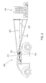
Figure 2 is a conceptual diagram illustrating a technique for determining an image capture location and an image capture direction when generating an augmented view of a location of interest, according to various embodiments of the present invention; -
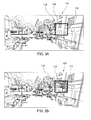
Figures 3A and 3B are conceptual diagrams illustrating a technique for generating an augmented view of a location of interest that is obstructed by a street corner, according to various embodiments of the present invention; -
Figure 4 is a conceptual diagram illustrating a technique for determining image capture location(s) and image capture direction(s) when generating an augmented view of a location of interest that is obstructed by a street corner, according to various embodiments of the present invention; -
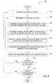
Figure 5 is a flow diagram of method steps for generating an augmented view of a location of interest for a user, according to various embodiments of the present invention; -
Figures 6A and 6B are conceptual diagrams illustrating a technique for generating a magnified view of a location of interest, according to various embodiments of the present invention; -
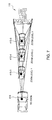
Figure 7 is a conceptual diagram illustrating a technique for determining an image capture location based on a zoom level when generating a magnified view of a location of interest, according to various embodiments of the present invention; -
Figure 8 is a flow diagram of method steps for generating a magnified view of a location ofinterest 110 for a user, according to various embodiments of the present invention; and -
Figure 9 is a block diagram illustrating a computing device configured to implement one or more aspects of the present invention. - In the following description, numerous specific details are set forth to provide a more thorough understanding of the embodiments of the present invention. However, it will be apparent to one of skill in the art that the embodiments of the present invention may be practiced without one or more of these specific details. The different features described above or below may be used in the described context, however, each feature may be combined with any of the other features described above or below if not explicitly stated otherwise.
-
Figure 1A-1C are conceptual diagrams illustrating a technique for compositing anunobstructed image 112 of a location ofinterest 110 with a real-time view 116 to generate an augmented view of the location ofinterest 110, according to various embodiments of the present invention. As shown inFigure 1A , when a user is traveling, objects in the surrounding environment may obstruct the user's view, interfering with the user's ability to see locations ofinterest 110 such as signs, streets, buildings, landmarks, and the like. For example, inFigure 1A , anobstruction 114 is blocking the user's view of a location of interest 110 (e.g., a building) to which the user is traveling. As a result, the user may not see the location ofinterest 110 in time to change traffic lanes and/or turn onto the appropriate street. Further, the user may unnecessarily expend attentional resources attempting to visually locate a location ofinterest 110 that is blocked by anobstruction 114, decreasing the user's ability to pay attention to pedestrians and other vehicles in the surrounding environment. - In order to enable the user to view a location of
interest 110 that is behind anobstruction 114, animage 112 of the location ofinterest 110 may be acquired from a database and/or from a camera that is positioned in the surrounding environment. Theimage 112 of the location ofinterest 110 may then be displayed in the user's field of view, enabling the user to view the location ofinterest 110 while simultaneously viewing his or her real-time surroundings. In various embodiments, theimage 112 of the location ofinterest 110 may be shown to the user on adisplay 120. Thedisplay 120 may be disposed on and/or projected onto any surface of the user's vehicle, including the windows (e.g., side windows, windshield, rear window, etc.), the mirrors (e.g., rearview mirror, side view mirrors, etc.), and/or a display screen. In some embodiments, thedisplay 120 is a heads-up display (HUD) that is substantially transparent, enabling the user to view the location ofinterest 110 while also viewing his or her real-time surroundings. Among other things, displayingimages 112 on atransparent display 120 allows the location ofinterest 110 to be composited with the user's real-time view 116, creating a substantially continuous view of the surrounding environment, as shown inFigure 1B . Additionally, as shown inFigure 1C , displaying theimages 112 on a transparent display allows the opacity of theimages 112 to be varied such that the user is able to view the obstruction 114 (e.g., the bus) in the same region of thedisplay 120 in which theimage 112 of the location ofinterest 110 is being displayed. Moreover, the opacity of theimage 112 of the location ofinterest 110 may be varied relative to the user's real-time view 116 by capturing real-time images of the user's line of sight, compositing the real-time images with theimages 112 of the location ofinterest 110, and displaying the composited images on thedisplay 120. Such techniques are described below in further detail in conjunction withFigure 2 . -
Figure 2 is a conceptual diagram of anavigation system 200 for displaying an augmented view of a location ofinterest 110 to a user, according to various embodiments of the present invention. As shown, thenavigation system 200 may include adisplay 120, acamera 210, and atracking device 220. Thecamera 210 may be configured to capture images of the user's surroundings, such as the real-time view 116 described above. Thecamera 210 may be located in a position that enables it to capture images from the user's point of view. For example, thecamera 210 may be located above, below, or to the side of the user's line of sight. In some embodiments, thecamera 210 may be mounted on a vehicle in which the user is traveling and/or on the user himself or herself. - In operation, the
navigation system 200 receives a location ofinterest 110. The location ofinterest 110 may be inputted by the user, determined by thenavigation system 200, and/or received from a secondary device. The location ofinterest 110 may include a street address, street number, name, city, state, coordinates, and/or any other information that enables thenavigation system 200 to determine the identity and/or the location ofinterest 110. Thenavigation system 200 may further determine the location of the user relative to the location ofinterest 110. The location of the user may be determined using any type of geolocation device, including Global Positioning System (GPS) devices, wireless communication devices, time-of-flight devices, radio frequency (RF) devices, optical devices, and the like. - After receiving the location of
interest 110, thenavigation system 200 receives animage 112 associated with the location ofinterest 110 from a database or from a camera that is located in the surrounding area. In some embodiments, the camera is proximate to the location ofinterest 110 such that the camera can capture anunobstructed image 112 of the location ofinterest 110 and transmit the image to thenavigation system 200. The database may be a navigation database, such as Google® Street View, that includes images of various streets and paths captured from multiple locations and from multiple directions. - The
image 112 of the location ofinterest 110 received from the database and/or captured by a camera is associated with an image capture location. The image capture location may be selected to provide the user with animage 112 of the location ofinterest 110 that is of an appropriate perspective (e.g., similar to the user's perspective) and is relatively unobstructed by objects in the surrounding environment. In various embodiments, the image capture location may be determined based on one or both of the location ofinterest 110 and the location of the user. For example, if the location ofinterest 110 is a place of business that is on a street along which the user is walking or driving, then the image capture location may be positioned between the user and the location ofinterest 110, for example, in the line of sight between the user and the location ofinterest 110. Thus, if the user is approaching the location ofinterest 110 from the south, then the image capture location may be positioned to the south of the location of interest 110 - between the location of the user and the location of interest 110 - in order to provide animage 112 having the proper perspective. - The
image 112 of the location ofinterest 110 received from the database and/or captured by a camera also may be associated with an image capture direction. As described above with respect to the image capture location, the image capture direction may be selected to provide the user with animage 112 of the location ofinterest 110 that is of an appropriate perspective (e.g., similar to the user's perspective). The image capture direction may be determined based on one or more of the location ofinterest 110, the location of the user, and the image capture location. For example, if the image capture location is positioned between the user and the location ofinterest 110, then the image capture direction may be selected to substantially match the direction of the line of sight from the user to the location ofinterest 110. Thus, if the user is approaching the location ofinterest 110 from the south, then the image capture direction may be substantially northward in order to provide animage 112 having the proper perspective. Alternatively, if the image capture location is not positioned substantially along the line of sight between the user and the location ofinterest 110, for example, if animage 112 associated with the image capture location described above is not available, then the image capture direction may be selected to compensate for the difference in perspective between the image capture location and the location of the user. In addition, theimage 112 itself may be processed (e.g., via a transform) to compensate for the difference in perspective between the image capture location and the location of the user, as is described below in further detail. - In various embodiments, the image capture location and/or image capture direction may be determined by comparing one or
more images 112 of the location ofinterest 110 that are stored in a database or captured by one or more cameras in the surrounding area to the real-time view 116 of the user. For example, thenavigation system 200 may compare one or more relevant portions of theimages 112 of the location of interest 110 - captured at one or more image capture locations and/or image capture directions - to corresponding portions of images of the real-time view 116 that are captured by thecamera 210. Thenavigation system 200 may then determine which image(s) are the closest match to the real-time view 116. These image(s) 112 may then be processed and displayed to the user on thedisplay 120, such as by applying a transform and compositing the image(s) 112 with the real-time view 116. - Prior to displaying the
image 112 of the location ofinterest 110 to the user on thedisplay 120, theimage 112 may be processed. Processing may include, for example, applying a transform to theimage 112, resizing theimage 112, cropping theimage 112, and/or combiningmultiple images 112 into asingle image 112 such that theimage 112 and the real-time view 116 are substantially continuous when theimage 112 is displayed to the user. In addition, the opacity of theimage 112 may be modified to more effectively blend theimage 112 with the real-time view 116 and/or to enable the user to simultaneously view both theimage 112 and corresponding portion(s) of the real-time view 116 (e.g., the obstruction 114). Further, in some embodiments, theimage 112 of the location ofinterest 110 may be composited with images of the real-time view 116, and the resulting composited image(s) may be displayed to the user on thedisplay 120. Compositing theimage 112 of the location ofinterest 110 with images of the real-time view 116 may be useful when thedisplay 120 is not in the line of sight between the user and the location ofinterest 110. In other embodiments, only the image 112 (e.g., the processed image 112) of the location ofinterest 110, but images of the real-time view 116, is displayed on thedisplay 120, such as on a vehicle window (e.g., the windshield). - The
tracking device 220 may include, without limitation, one or more cameras and/or sensors configured to determine the position and/or eye gaze direction 223 (e.g., horizontal angle and/or vertical angle) of the user. Images acquired by the camera(s) and/or sensor(s) may be analyzed by a computing device included in thetracking device 220 and/or associated with thenavigation system 200. For example, as shown inFigure 2 , a camera may be configured to acquire images of a user's eyes or face. The images may then be analyzed to determine the position of the user relative to thedisplay 120 and/or the direction in which the user is looking. - The position of the user and/or the
eye gaze direction 223 may be used to determine the location ofinterest 110, the image capture location, and/or the image capture direction. For example, the user may activate an augmented view function of thenavigation device 200 and then look in the direction of a location ofinterest 110. In response, thetracking device 220 may detect the user'seye gaze direction 223 and transmit theeye gaze direction 223 to a computing device associated with thenavigation system 200. The computing device may then use theeye gaze direction 223 to determine the location ofinterest 110 at which the user is looking and to select an appropriate image capture location and/or image capture direction.Images 112 associated with the image capture location and/or image capture direction may then be displayed to the user. Further, the position of the user relative to the display 120 (e.g., the position of the user within the vehicle) may be used to determine and/or refine the image capture location and/or image capture direction. For example, if the user moves to the left or right within the vehicle, then the image capture location and/or image capture direction may be modified so that theimage 112 of the location ofinterest 110 displayed to the user more accurately reflects the user's perspective. Moreover, the position of the user relative to thedisplay 120 may be used to determine how to process the image 112 (e.g., via transform, zooming, cropping, etc.) prior to displaying theimage 112 to the user. - Once the
navigation system 200 receives animage 112 of the location ofinterest 110, theimage 112 may be processed to compensate for the difference in the height at which theimage 112 was captured and the height of the user's line of sight. For example, if theimage 112 is acquired from a database, such as Google® Street View, then theimage 112 may have been captured at a height that is above the user's line of sight. Accordingly, a transform may be applied to theimage 112 to compensate for theangle 222 between the line of sight of the user and the line of sight of the camera (e.g., Google® Street View camera). - In some embodiments, the
navigation device 200 is worn by the user. For example, thenavigation device 200 may be a headset or pair of glasses worn by the user. In such embodiments, thecamera 210,tracking device 220, and/ordisplay 120 could be positioned in thenavigation device 200 proximate to the user's eyes to determine theeye gaze direction 223 and provide the user withimages 112 of the location ofinterest 110. For example, one or more cameras may be positioned in a headset or pair of glasses near the user's eyes. - Under certain circumstances, a user of the
navigation device 200 may wish to view a location ofinterest 110 that is on the other side of a street corner. For example, when a user is traveling, the user may wish to view what is on a particular street, prior to reaching the street, in order to determine whether he or she should turn down the street. Accordingly, some of the techniques described above may be applied to provide the user withimages 112 of the buildings and/or other locations ofinterest 110 that are around a street corner. Such implementations are discussed below in conjunction withFigures 3A-5 . -
Figures 3A and 3B are conceptual diagrams illustrating a technique for generating an augmented view of a location ofinterest 110 that is obstructed by a street corner, according to various embodiments of the present invention. As shown, when approaching a street corner, a user may wish to view the buildings, landmarks, signs, etc. that are being obstructed by the street corner. Accordingly, the user may activate an augmented view function of thenavigation device 200 and input the relevant location of interest 110 (e.g., via a keyboard, voice command,eye gaze direction 223, and the like). In response, thenavigation system 200 may determine an image capture location and/or image capture direction based on the location of the user relative to the location ofinterest 110, as described below in further detail in conjunction withFigure 4 . Thenavigation system 200 may then receive animage 112 of the location ofinterest 110 based on the image capture location and/or image capture direction and perform optional processing on theimage 112. Theimage 112 is then displayed to the user on thedisplay 120. For example, as shown inFigure 3B , theimage 112 of a location ofinterest 110 that is on the other side of a street corner may be displayed to the user on atransparent display 120, such as a car window, enabling the user to view the real-time view 116 in conjunction with theimage 112. -
Figure 4 is a conceptual diagram illustrating a technique for determining image capture location(s) 415 and image capture direction(s) when generating an augmented view of a location ofinterest 110 that is obstructed by a street corner, according to various embodiments of the present invention. As shown, one ormore images 112, each associated with a different image capture location 415 and/or image capture direction, may be acquired from a database and/or from a camera that is proximate to the location ofinterest 110. Whenmultiple images 112 are acquired, theimages 112 may be combined to form a single,continuous image 112 that is displayed to the user. Additionally, the image(s) 112 may be combined with the real-time view 116 of the user. For example, as shown, images of real-time view 116-1 and real-time view 116-2, associated with the location of theuser 410, may be combined with an image 112-1 captured at image capture location 415-1 and an image 112-2 captured at image capture location 415-2 to form a continuous image that is displayed to the user. In other embodiments, the continuous image may be generated by combining only image 112-1 and image 112-2. The resultingimage 112 may then be processed (e.g., according to the perspective of the user) and displayed in the appropriate position in the field of view of the user so that theimage 112 appears substantially continuous with real-time view 116-1 and real-time view 116-2. - In addition to compositing the real-time view(s) 116 with the
images 112 of the location ofinterest 110, the real-time view(s) 116 may be used to determine which image capture location(s) and/or image capture direction(s) provide the closest match to the real-time view 116 associated with the location of theuser 410. For example, a computing device associated withnavigation system 200 may compare one or more portions of the real-time view 116 (e.g., real-time view 116-1 and 116-2) to one or more corresponding portions ofimages 112 acquired from a database or camera to determine which image(s) 112 most closely match the perspective of the user.Images 112 that provide an appropriate level of continuity with the real-time view 116 may then be processed and displayed to the user. -
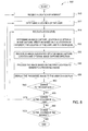
Figure 5 is a flow diagram of method steps for generating an augmented view of a location of interest for a user, according to various embodiments of the present invention. Although the method steps are described in conjunction with the systems ofFigures 1-4 , persons skilled in the art will understand that any system configured to perform the method steps, in any order, falls within the scope of the present invention. - As shown, a
method 500 begins atstep 510, where thenavigation system 200 receives a location ofinterest 110. The location ofinterest 110 may be inputted by the user, determined by thenavigation system 200, and/or received from a secondary device. Atstep 515, thenavigation system 200 determines the location of the user. The location of the user may be determined using any type of geolocation device, including Global Positioning System (GPS) devices, wireless communication devices, time-of-flight devices, radio frequency (RF) devices, optical devices, and the like. - Next, at
step 520, thenavigation system 200 determines an image capture location based on the location ofinterest 110 and the location of the user. Atstep 525, thenavigation system 200 may determine an image capture direction based on the location ofinterest 110, the location of the user, and/or the image capture location. Then, atstep 530, thenavigation system 200 receives animage 112 of the location ofinterest 110 associated with the image capture location and the optional image capture direction. - At
step 540, thenavigation system 200 and/or a computing device associated with thenavigation system 200 may process theimage 112. Processing may include, for example, applying a transform to theimage 112, resizing theimage 112, cropping theimage 112, combiningmultiple images 112 into asingle image 112, and the like. Atstep 550, the processedimage 112 is displayed to the user on adisplay 120. - At
step 560, thenavigation system 200 determines whether there has been a change to the location of the user. If there has been a change to the location of the user, then themethod 500 returns to step 515, where the location of the user is determined. If there has not been a change to the location of the user, then themethod 500 proceeds to step 570. Atstep 570, thenavigation system 200 determines whether there has been a change to the location ofinterest 110. If there has been a change to the location ofinterest 110, then themethod 500 returns to step 510, where a different location ofinterest 110 is received. If there has not been a change to the location of interest, then themethod 500 ends. - In addition to generating an augmented view of an obstructed location of
interest 110 for a user, thenavigation system 200 may be configured to generate an augmented view of a location ofinterest 110 that is relatively unobstructed, but which is relatively far away from the user. Such implementations are illustrated inFigures 6A and 6B , which are conceptual diagrams illustrating a technique for generating a magnified view of a location ofinterest 110, according to various embodiments of the present invention. As shown inFigure 6A , when a user is approaching an unobstructed location ofinterest 110, the user may wish to more easily view details associated with the location ofinterest 110. Accordingly, thenavigation system 200 may acquire animage 112 of the location ofinterest 110 and display theimage 112 on thedisplay 120 according to a zoom level specified by the user or determined by thenavigation system 200. The resultingimage 112 of the location ofinterest 110 is shown inFigure 6B . As shown, by generating a magnified image of the location ofinterest 110, the user may more easily view details associated with the location ofinterest 110. - The magnified
image 112 displayed to the user may be acquired from a database, as described above, or from a camera that is proximate to the location ofinterest 110. Such implementations are described in further detail below in conjunction withFigure 6 . Alternatively, the magnifiedimage 112 displayed to the user may be acquired by a camera (e.g., camera 210) associated with thenavigation system 200 and/or coupled to the user or the user's vehicle. For example, thecamera 210 associated with thenavigation system 200 may provide a magnifiedimage 112 of the location ofinterest 110 via an optical zoom or digital zoom function. In other embodiments, animage 112 captured by thecamera 210 may be magnified by a computing device associated with thenavigation system 200. The magnifiedimage 112 may then be displayed to the user in an appropriate position relative to the real-time view 116. -
Figure 7 is a conceptual diagram illustrating a technique for determining an image capture location based on a zoom level when generating a magnified view of a location ofinterest 110, according to various embodiments of the present invention. As shown, the image capture location 415 selected by thenavigation system 200 may be based on a zoom level specified by the user or selected by thenavigation system 200. For example, image capture location 415-3 may be selected by thenavigation system 200 if the user inputs a relatively low zoom level, such as a zoom level of 2x, and image capture location 415-5 may be selected by thenavigation system 200 if the user inputs a relatively high zoom level, such as a zoom level of 24x. In various embodiments, the user may specify the zoom level at which the location ofinterest 110 is to be displayed by issuing a voice command to thenavigation system 200 or by inputting the zoom level on a keyboard, switch, knob, or other input device. - In addition to selecting an appropriate image capture location based on the zoom level, in some embodiments, an image capture direction may be selected to provide an
image 112 having the appropriate perspective, as described above in conjunction withFigures 1A-5 . Moreover, theimage 112 acquired for a given zoom level may be processed according to the techniques described above to compensate for a difference in perspective between the image capture location and the location of theuser 410. Further, although theimages 112 inFigure 6 are illustrated as being captured by vehicles, such as a Google® Street View vehicle or a vehicle positioned in the surrounding environment (e.g., via vehicle-to-vehicle (V2V) communication), theimages 112 may be captured from other objects (e.g., surveillance cameras on poles, street signs, buildings, etc.) and locations in the surrounding environment. - In some embodiments, the techniques for viewing a location of
interest 110 that is obstructed by an object and/or a street corner, described above in conjunction withFigures 1A-5 , may be combined with the techniques for displaying a magnifiedimage 112 of a location ofinterest 110 to a user, described above in conjunction withFigures 6A-7 . For example, instead of display animage 112 of the location ofinterest 110 to generate a continuous image from the perspective of the user, theimage 112 may be magnified to enable the user to more easily view details associated with the location ofinterest 110. As described above, magnification of theimage 112 may be specified by the user and/or selected by the navigation system to provide zoom levels ranging from no zoom-such that theimage 112 is substantially continuous with the real-time view 116-to a high level of zoom (e.g., 12x, 24x, or higher). -
Figure 8 is a flow diagram of method steps for generating a magnified view of a location of interest for a user, according to various embodiments of the present invention. Although the method steps are described in conjunction with the systems ofFigures 1-4 and6-7 , persons skilled in the art will understand that any system configured to perform the method steps, in any order, falls within the scope of the present invention. - As shown, a
method 800 begins atstep 810, where thenavigation system 200 receives a location ofinterest 110. Atstep 812, thenavigation system 200 determines the location of the user. Atstep 814, thenavigation system 200 receives a zoom level. The zoom level may be selected by the navigation system 200 (e.g., based on an algorithm), or the user may specify the zoom level by issuing a voice command to thenavigation system 200 or by inputting the zoom level on a keyboard, switch, knob, or other input device. - Next, at
step 820, thenavigation system 200 determines an image capture location and optional image capture direction based on the location ofinterest 110, the location of the user, and/or the zoom level. Atstep 830, thenavigation system 200 receives animage 112 of the location ofinterest 110 associated with the image capture location and the optional image capture direction. Then, atstep 840, thenavigation system 200 and/or a computing device associated with thenavigation system 200 may process theimage 112. Atstep 850, the processedimage 112 is displayed to the user on adisplay 120. - At
step 860, thenavigation system 200 determines whether there has been a change to the zoom level. If there has been a change to the zoom level, then themethod 800 returns to step 814, where a different zoom level is received. If there has not been a change to the zoom level, then themethod 800 proceeds to step 870. Atstep 870, thenavigation system 200 determines whether there has been a change to the location of the user. If there has been a change to the location of the user, then themethod 800 returns to step 812, where the location of the user is determined. If there has not been a change to the location of the user, then themethod 800 proceeds to step 880. Atstep 880, thenavigation system 200 determines whether there has been a change to the location ofinterest 110. If there has been a change to the location ofinterest 110, then themethod 800 returns to step 810, where a different location ofinterest 110 is received. If there has not been a change to the location of interest, then themethod 800 ends. -
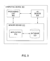
Figure 9 is a block diagram illustrating acomputing device 900 configured to implement one or more aspects of the present invention. As shown,computing device 900 includes aprocessing unit 902, input/output (I/O)devices 904, and amemory unit 910.Memory unit 910 includes anapplication 912 configured to interact with adatabase 914. -
Processing unit 902 may include a central processing unit (CPU), digital signal processing unit (DSP), and so forth. I/O devices 904 may include input devices, output devices, and devices capable of both receiving input and providing output.Memory unit 910 may include a memory module or a collection of memory modules.Software application 912 withinmemory unit 910 may be executed by processingunit 902 to implement the overall functionality ofcomputing device 900, and, thus, to coordinate the operation of thenavigation system 200 as a whole. Thedatabase 914 may store locations ofinterest 110,images 112, images associated with real-time views 116, GPS coordinates, object locations, object distances, lookup tables, and other data for generating augmented views of locations ofinterest 110 and acquiring information associated with the locations ofinterest 110. -
Computing device 900 may be coupled to thecamera 210 and thetracking device 220. Thecamera 210 may be configured to capture images of a real-time view 116 of a user. Thetracking device 220 may include one or more sensors, such as one or more cameras and/or depth sensors. Thetracking device 220 may be configured to measure various properties of the environment within which user resides, as well as various properties associated with user (e.g., location, position, orientation, and eye gaze direction 223). Thetracking device 220 may include any number of cameras, depth sensors, light sensors, or any other type of sensor. Generally, thetracking device 220 captures sensory data associated with the environment and sensory data associated with user, and provides that data tocomputing device 900. -
Computing device 900 as a whole may be a microprocessor, an application-specific integrated circuit (ASIC), a system-on-a-chip (SoC), a mobile computing device such as a tablet computer or cell phone, a media player, and so forth. Generally,computing device 900 is configured to coordinate the overall operation of thenavigation system 200. Any technically feasible system configured to implement the functionality of thenavigation system 200 falls within the scope of the present invention. - In sum, a navigation system determines an image capture location and an image capture direction based on a location of interest and a location of a user. The navigation system then receives an image of the location of interest from a database and/or from a camera that is proximate to the location of interest. The image is based on the image capture location and/or the image capture direction. Next, the navigation system may process the image by applying a transform based on the location of the user. The processed image is then displayed to the user.
- One advantage of the techniques described herein is that a user is able to see through obstructions in the surrounding environment to view a location of interest. Additionally, the disclosed techniques enable the user to continue to pay attention to his or her real-time surroundings while viewing the location of interest. Accordingly, by overlaying an image of the location of interest with the user's real-time field of view, navigation efficacy and user safety are increased.
- One embodiment of the invention may be implemented as a program product for use with a computing device. The program(s) of the program product define functions of the embodiments (including the methods described herein) and can be contained on a variety of computer-readable storage media. Illustrative computer-readable storage media include, but are not limited to: (i) non-writable storage media (e.g., read-only memory devices within a computer such as compact disc read only memory (CD-ROM) disks readable by a CD-ROM drive, flash memory, read only memory (ROM) chips or any type of solid-state non-volatile semiconductor memory) on which information is permanently stored; and (ii) writable storage media (e.g., floppy disks within a diskette drive or hard-disk drive or any type of solid-state random-access semiconductor memory) on which alterable information is stored.
- The invention has been described above with reference to specific embodiments. Persons of ordinary skill in the art, however, will understand that various modifications and changes may be made thereto without departing from the broader spirit and scope of the invention as set forth in the appended claims. For example, although many of the descriptions herein refer to the user as a driver or passenger of a vehicle, persons skilled in the art will appreciate that the systems and techniques described herein are applicable to other situations (e.g., non-vehicular) in which generating augmented views of a location of interest may enhance user experience and/or user safety. The foregoing description and drawings are, accordingly, to be regarded in an illustrative rather than a restrictive sense.
- Therefore, the scope of embodiments of the present invention is set forth in the claims that follow.
Claims (15)
- A computer-implemented method for generating an augmented view of a location of interest (110) for a user, the method comprising:determining an image capture location based on the location of interest (110);determining an image capture direction based on the image capture location;receiving an image (112) associated with the image capture location and the image capture direction;processing the image (112) based on a line of sight associated with a location of the user to generate a processed image; anddisplaying the processed image to the user.
- The method of claim 1, wherein processing the image comprises projecting the line of sight through a surface of a display (120) to determine a transform, and applying the transform to the image (112).
- The method of claim 2, wherein an automobile window comprises the surface of the display (120).
- The method of any of the preceding claims, further comprising receiving an image of a real-time view (116) associated with the line of sight, and wherein processing the image comprises comparing the image (112) to the image of the real-time view (116), and aligning at least one portion of the image with at least one portion of the image of the real-time view.
- The method of claim 4, wherein the image of the real-time view (116) comprises an obstructed view of the location of interest (110), and the image comprises a substantially unobstructed view of the location of interest (110).
- The method of claim 4, wherein processing the image further comprises compositing the image with the image of the real-time view (116).
- The method of any of the precedings claims, further comprising receiving a zoom value from the user, and wherein determining the image capture location is further based on the zoom value.
- The method of any of the precedings claims, further comprising receiving coordinates from a database that define the location of interest (110), and wherein the location of the user is derived from one or more geolocation signals.
- The method of any of the precedings claims, further comprising determining an eye gaze direction (223) of the user, and selecting the location of interest (110) based on the location of the user and the eye gaze direction.
- A system for generating an augmented view of a location of interest for a user, comprising:a processing unit (902) configured to:determine a first image capture location based on a location of the user and the location of interest (110);receive a first image acquired at the first image capture location; andprocess the first image based on a line of sight associated with the location of the user to generate a processed image; anda display (120) configured to display the processed image to the user.
- The system of claim 10, wherein the processing unit (902) is further configured to determine an image capture direction based on the first image capture location and the location of interest, and the first image is associated with the image capture direction.
- The system of claim 10 or 11, wherein the processing unit (902) is configured to process the first image by projecting the line of sight through a surface of the display to determine a transform and applying the transform to the first image.
- The system of claim 12, wherein the display is disposed in an automobile window.
- The system of any of claims 10 to 13, further comprising a tracking device (220) configured to determine an eye gaze direction (223) of the user, and wherein the processing unit is further configured to receive the eye gaze direction and select the location of interest (110) based on the location of the user and the eye gaze direction.
- A non-transitory computer-readable storage medium including instructions that, when executed by a processing unit, cause the processing unit to generate an augmented view of a location of interest for a user according to a method as mentioned in any of claims 1 to 9.
Applications Claiming Priority (1)
| Application Number | Priority Date | Filing Date | Title |
|---|---|---|---|
| US14/183,364 US9639968B2 (en) | 2014-02-18 | 2014-02-18 | Generating an augmented view of a location of interest |
Publications (2)
| Publication Number | Publication Date |
|---|---|
| EP2911041A1 true EP2911041A1 (en) | 2015-08-26 |
| EP2911041B1 EP2911041B1 (en) | 2020-07-08 |
Family
ID=52596313
Family Applications (1)
| Application Number | Title | Priority Date | Filing Date |
|---|---|---|---|
| EP15155018.3A Active EP2911041B1 (en) | 2014-02-18 | 2015-02-13 | Generating an augmented view of a location of interest |
Country Status (4)
| Country | Link |
|---|---|
| US (1) | US9639968B2 (en) |
| EP (1) | EP2911041B1 (en) |
| JP (1) | JP6487231B2 (en) |
| CN (1) | CN104848863B (en) |
Cited By (7)
| Publication number | Priority date | Publication date | Assignee | Title |
|---|---|---|---|---|
| CN106973237A (en) * | 2017-05-25 | 2017-07-21 | 维沃移动通信有限公司 | A kind of image pickup method and mobile terminal |
| WO2018085613A2 (en) | 2016-11-04 | 2018-05-11 | X Development Llc | Intuitive occluded object indicator |
| EP3342645A1 (en) * | 2017-01-02 | 2018-07-04 | Connaught Electronics Ltd. | Method for providing at least one information from an environmental region of a motor vehicle, display system for a motor vehicle driver assistance system for a motor vehicle as well as motor vehicle |
| CN109427219A (en) * | 2017-08-29 | 2019-03-05 | 深圳市掌网科技股份有限公司 | Take precautions against natural calamities learning method and device based on augmented reality education scene transformation model |
| RU2715876C1 (en) * | 2016-04-14 | 2020-03-03 | Ниссан Мотор Ко., Лтд. | Method and equipment for displaying neighbourhoods of mobile body |
| CN111527517A (en) * | 2017-12-25 | 2020-08-11 | 佳能株式会社 | Image processing apparatus and control method thereof |
| US11830177B2 (en) | 2017-12-25 | 2023-11-28 | Canon Kabushiki Kaisha | Image processing apparatus, control method and non-transitory computer-readable recording medium therefor |
Families Citing this family (34)
| Publication number | Priority date | Publication date | Assignee | Title |
|---|---|---|---|---|
| US9972121B2 (en) * | 2014-04-22 | 2018-05-15 | Google Llc | Selecting time-distributed panoramic images for display |
| USD780777S1 (en) | 2014-04-22 | 2017-03-07 | Google Inc. | Display screen with graphical user interface or portion thereof |
| USD781318S1 (en) | 2014-04-22 | 2017-03-14 | Google Inc. | Display screen with graphical user interface or portion thereof |
| US9934222B2 (en) | 2014-04-22 | 2018-04-03 | Google Llc | Providing a thumbnail image that follows a main image |
| USD781317S1 (en) | 2014-04-22 | 2017-03-14 | Google Inc. | Display screen with graphical user interface or portion thereof |
| US20170061689A1 (en) * | 2015-08-24 | 2017-03-02 | Caterpillar Inc. | System for improving operator visibility of machine surroundings |
| US20170090196A1 (en) * | 2015-09-28 | 2017-03-30 | Deere & Company | Virtual heads-up display application for a work machine |
| JP6456516B2 (en) * | 2015-10-30 | 2019-01-23 | 三菱電機株式会社 | Driving assistance device |
| WO2017206042A1 (en) * | 2016-05-31 | 2017-12-07 | 中国科学院深圳先进技术研究院 | Method and apparatus for seeing through obstruction using smart glasses |
| CN109478334B (en) * | 2016-07-20 | 2021-04-20 | 富士胶片株式会社 | Target position recognition device, imaging device, display device, target position recognition method, and non-transitory tangible medium |
| KR20230133940A (en) | 2016-07-25 | 2023-09-19 | 매직 립, 인코포레이티드 | Imaging modification, display and visualization using augmented and virtual reality eyewear |
| US20190221184A1 (en) * | 2016-07-29 | 2019-07-18 | Mitsubishi Electric Corporation | Display device, display control device, and display control method |
| JP2018032991A (en) * | 2016-08-24 | 2018-03-01 | 富士通株式会社 | Image display unit, image display method and computer program for image display |
| US10558264B1 (en) | 2016-12-21 | 2020-02-11 | X Development Llc | Multi-view display with viewer detection |
| USD844028S1 (en) * | 2017-06-04 | 2019-03-26 | Apple Inc. | Display screen or portion thereof with graphical user interface |
| US10885672B2 (en) | 2017-06-14 | 2021-01-05 | Behr Process Corporation | Systems and methods for analyzing colors from a social media platform |
| US10349011B2 (en) * | 2017-08-14 | 2019-07-09 | GM Global Technology Operations LLC | System and method for improved obstacle awareness in using a V2X communications system |
| DE102017129214B4 (en) * | 2017-12-08 | 2024-01-18 | Grammer Aktiengesellschaft | System and method for improving a field of vision |
| US10544567B2 (en) | 2017-12-22 | 2020-01-28 | Caterpillar Inc. | Method and system for monitoring a rotatable implement of a machine |
| US10901687B2 (en) | 2018-02-27 | 2021-01-26 | Dish Network L.L.C. | Apparatus, systems and methods for presenting content reviews in a virtual world |
| US11343613B2 (en) * | 2018-03-08 | 2022-05-24 | Bose Corporation | Prioritizing delivery of location-based personal audio |
| AT521130A1 (en) * | 2018-04-04 | 2019-10-15 | Peterseil Thomas | Method for displaying a virtual object |
| JP7033029B2 (en) * | 2018-07-30 | 2022-03-09 | 本田技研工業株式会社 | Controls and programs |
| JP7087844B2 (en) * | 2018-08-31 | 2022-06-21 | トヨタ自動車株式会社 | Image processing equipment, image processing system and vehicle |
| US11538045B2 (en) | 2018-09-28 | 2022-12-27 | Dish Network L.L.C. | Apparatus, systems and methods for determining a commentary rating |
| JP2020065141A (en) * | 2018-10-16 | 2020-04-23 | 現代自動車株式会社Hyundai Motor Company | Vehicle overhead image generation system and method thereof |
| DE102018219481A1 (en) * | 2018-11-15 | 2020-05-20 | Robert Bosch Gmbh | Assembly for a LiDAR sensor and LiDAR sensor |
| EP3884300A4 (en) * | 2018-11-19 | 2022-07-27 | Suteng Innovation Technology Co., Ltd. | Lidar signal receiving circuits, lidar signal gain control methods, and lidars using the same |
| US11016630B2 (en) | 2019-01-31 | 2021-05-25 | International Business Machines Corporation | Virtual view-window |
| US20220228879A1 (en) * | 2019-06-11 | 2022-07-21 | Sony Group Corporation | Information processing device, information processing method, and program |
| CN111703371B (en) * | 2020-06-16 | 2023-04-07 | 阿波罗智联(北京)科技有限公司 | Traffic information display method and device, electronic equipment and storage medium |
| JP2024049400A (en) * | 2021-01-29 | 2024-04-10 | 株式会社Nttドコモ | Information Processing System |
| KR20240026503A (en) * | 2021-06-30 | 2024-02-28 | 스냅 인코포레이티드 | Augmented reality eyewear with x-ray effect |
| US11635808B2 (en) * | 2021-08-12 | 2023-04-25 | International Business Machines Corporation | Rendering information in a gaze tracking device on controllable devices in a field of view to remotely control |
Citations (5)
| Publication number | Priority date | Publication date | Assignee | Title |
|---|---|---|---|---|
| US20070139523A1 (en) * | 2005-12-15 | 2007-06-21 | Toshio Nishida | Photographing apparatus, image signal choosing apparatus, driving assisting apparatus and automobile |
| US20090140881A1 (en) * | 2007-09-14 | 2009-06-04 | Denso Corporation | Vehicle-use visual field assistance system in which information dispatch apparatus transmits images of blind spots to vehicles |
| US20100315215A1 (en) * | 2008-03-27 | 2010-12-16 | Panasonic Corporation | Blind spot display apparatus |
| EP2372627A2 (en) * | 2010-04-01 | 2011-10-05 | Richard E. Rowe | Providing city services using mobile devices and a sensor network |
| WO2011135778A1 (en) * | 2010-04-26 | 2011-11-03 | パナソニック株式会社 | Image processing device, car navigation system, and on-street camera system |
Family Cites Families (18)
| Publication number | Priority date | Publication date | Assignee | Title |
|---|---|---|---|---|
| US6917370B2 (en) * | 2002-05-13 | 2005-07-12 | Charles Benton | Interacting augmented reality and virtual reality |
| JP2004234455A (en) * | 2003-01-31 | 2004-08-19 | Canon Inc | Information processing method and image reproducing apparatus |
| US7619626B2 (en) * | 2003-03-01 | 2009-11-17 | The Boeing Company | Mapping images from one or more sources into an image for display |
| US7148861B2 (en) * | 2003-03-01 | 2006-12-12 | The Boeing Company | Systems and methods for providing enhanced vision imaging with decreased latency |
| JP2005311868A (en) * | 2004-04-23 | 2005-11-04 | Auto Network Gijutsu Kenkyusho:Kk | Vehicle periphery visually recognizing apparatus |
| JP4401890B2 (en) * | 2004-07-29 | 2010-01-20 | 本田技研工業株式会社 | Vehicle recognition support device |
| US20060210111A1 (en) * | 2005-03-16 | 2006-09-21 | Dixon Cleveland | Systems and methods for eye-operated three-dimensional object location |
| JP2007156637A (en) * | 2005-12-01 | 2007-06-21 | Mitsubishi Electric Corp | Information retrieval device, program and information retrieval system |
| EP2036043A2 (en) * | 2006-06-26 | 2009-03-18 | Lockheed Martin Corporation | Method and system for providing a perspective view image by intelligent fusion of a plurality of sensor data |
| US8237791B2 (en) * | 2008-03-19 | 2012-08-07 | Microsoft Corporation | Visualizing camera feeds on a map |
| KR20100055254A (en) * | 2008-11-17 | 2010-05-26 | 엘지전자 주식회사 | Method for providing poi information for mobile terminal and apparatus thereof |
| JP2011152865A (en) * | 2010-01-27 | 2011-08-11 | Kyocera Corp | On-vehicle image pickup device |
| US8436872B2 (en) * | 2010-02-03 | 2013-05-07 | Oculus Info Inc. | System and method for creating and displaying map projections related to real-time images |
| US20120224060A1 (en) * | 2011-02-10 | 2012-09-06 | Integrated Night Vision Systems Inc. | Reducing Driver Distraction Using a Heads-Up Display |
| US9255813B2 (en) * | 2011-10-14 | 2016-02-09 | Microsoft Technology Licensing, Llc | User controlled real object disappearance in a mixed reality display |
| CN104093447A (en) * | 2012-01-16 | 2014-10-08 | 泰索医疗公司 | A device for treatment of a wound |
| DE102012200731A1 (en) * | 2012-01-19 | 2013-07-25 | Robert Bosch Gmbh | Method and device for visualizing the environment of a vehicle |
| US9092896B2 (en) * | 2012-08-07 | 2015-07-28 | Microsoft Technology Licensing, Llc | Augmented reality display of scene behind surface |
-
2014
- 2014-02-18 US US14/183,364 patent/US9639968B2/en active Active
-
2015
- 2015-02-10 JP JP2015023924A patent/JP6487231B2/en active Active
- 2015-02-13 EP EP15155018.3A patent/EP2911041B1/en active Active
- 2015-02-13 CN CN201510079359.7A patent/CN104848863B/en active Active
Patent Citations (5)
| Publication number | Priority date | Publication date | Assignee | Title |
|---|---|---|---|---|
| US20070139523A1 (en) * | 2005-12-15 | 2007-06-21 | Toshio Nishida | Photographing apparatus, image signal choosing apparatus, driving assisting apparatus and automobile |
| US20090140881A1 (en) * | 2007-09-14 | 2009-06-04 | Denso Corporation | Vehicle-use visual field assistance system in which information dispatch apparatus transmits images of blind spots to vehicles |
| US20100315215A1 (en) * | 2008-03-27 | 2010-12-16 | Panasonic Corporation | Blind spot display apparatus |
| EP2372627A2 (en) * | 2010-04-01 | 2011-10-05 | Richard E. Rowe | Providing city services using mobile devices and a sensor network |
| WO2011135778A1 (en) * | 2010-04-26 | 2011-11-03 | パナソニック株式会社 | Image processing device, car navigation system, and on-street camera system |
Cited By (12)
| Publication number | Priority date | Publication date | Assignee | Title |
|---|---|---|---|---|
| RU2715876C1 (en) * | 2016-04-14 | 2020-03-03 | Ниссан Мотор Ко., Лтд. | Method and equipment for displaying neighbourhoods of mobile body |
| US10864856B2 (en) | 2016-04-14 | 2020-12-15 | Nissan Motor Co., Ltd. | Mobile body surroundings display method and mobile body surroundings display apparatus |
| WO2018085613A2 (en) | 2016-11-04 | 2018-05-11 | X Development Llc | Intuitive occluded object indicator |
| EP3519235A4 (en) * | 2016-11-04 | 2020-07-01 | X Development LLC | Intuitive occluded object indicator |
| EP3342645A1 (en) * | 2017-01-02 | 2018-07-04 | Connaught Electronics Ltd. | Method for providing at least one information from an environmental region of a motor vehicle, display system for a motor vehicle driver assistance system for a motor vehicle as well as motor vehicle |
| CN106973237A (en) * | 2017-05-25 | 2017-07-21 | 维沃移动通信有限公司 | A kind of image pickup method and mobile terminal |
| CN109427219A (en) * | 2017-08-29 | 2019-03-05 | 深圳市掌网科技股份有限公司 | Take precautions against natural calamities learning method and device based on augmented reality education scene transformation model |
| CN111527517A (en) * | 2017-12-25 | 2020-08-11 | 佳能株式会社 | Image processing apparatus and control method thereof |
| EP3734540A4 (en) * | 2017-12-25 | 2021-10-27 | Canon Kabushiki Kaisha | Image processing apparatus and control method therefor |
| US11416978B2 (en) | 2017-12-25 | 2022-08-16 | Canon Kabushiki Kaisha | Image processing apparatus, control method and non-transitory computer-readable recording medium therefor |
| CN111527517B (en) * | 2017-12-25 | 2023-09-22 | 佳能株式会社 | Image processing apparatus and control method thereof |
| US11830177B2 (en) | 2017-12-25 | 2023-11-28 | Canon Kabushiki Kaisha | Image processing apparatus, control method and non-transitory computer-readable recording medium therefor |
Also Published As
| Publication number | Publication date |
|---|---|
| CN104848863A (en) | 2015-08-19 |
| US9639968B2 (en) | 2017-05-02 |
| CN104848863B (en) | 2019-08-20 |
| EP2911041B1 (en) | 2020-07-08 |
| JP6487231B2 (en) | 2019-03-20 |
| JP2015153426A (en) | 2015-08-24 |
| US20150235398A1 (en) | 2015-08-20 |
Similar Documents
| Publication | Publication Date | Title |
|---|---|---|
| US9639968B2 (en) | Generating an augmented view of a location of interest | |
| JP5798392B2 (en) | Parking assistance device | |
| JP6176541B2 (en) | Information display device, information display method, and program | |
| US8624717B2 (en) | Image processor, storage medium storing an image processing program and vehicle-mounted terminal | |
| US11511627B2 (en) | Display device and computer program | |
| US9952665B2 (en) | Eye vergence detection on a display | |
| US8880344B2 (en) | Method for displaying images on a display device and driver assistance system | |
| JP4895313B2 (en) | Navigation apparatus and method | |
| US20160185219A1 (en) | Vehicle-mounted display control device | |
| US20150302259A1 (en) | Driving assistance device and image processing program | |
| JP2014181927A (en) | Information provision device, and information provision program | |
| CN111273765B (en) | Vehicle display control device, vehicle display control method, and storage medium | |
| RU2677122C1 (en) | Vehicle displaying device | |
| US11525694B2 (en) | Superimposed-image display device and computer program | |
| WO2019224922A1 (en) | Head-up display control device, head-up display system, and head-up display control method | |
| US10996469B2 (en) | Method and apparatus for providing driving information of vehicle, and recording medium | |
| JP2020032866A (en) | Vehicular virtual reality providing device, method and computer program | |
| US9423267B2 (en) | Navigation device and display control method | |
| JPWO2017013792A1 (en) | Display control device and navigation device | |
| JP2008002965A (en) | Navigation device and method therefor | |
| EP3388922A1 (en) | Method and device for guiding a user to a virtual object | |
| JP2020086884A (en) | Lane marking estimation device, display control device, method and computer program | |
| JP2014174880A (en) | Information processor and information program | |
| JP2014174091A (en) | Information providing device and information providing program | |
| JP7215191B2 (en) | Driving support control device, driving support control method, and program |
Legal Events
| Date | Code | Title | Description |
|---|---|---|---|
| PUAI | Public reference made under article 153(3) epc to a published international application that has entered the european phase |
Free format text: ORIGINAL CODE: 0009012 |
|
| AK | Designated contracting states |
Kind code of ref document: A1 Designated state(s): AL AT BE BG CH CY CZ DE DK EE ES FI FR GB GR HR HU IE IS IT LI LT LU LV MC MK MT NL NO PL PT RO RS SE SI SK SM TR |
|
| AX | Request for extension of the european patent |
Extension state: BA ME |
|
| 17P | Request for examination filed |
Effective date: 20160226 |
|
| RBV | Designated contracting states (corrected) |
Designated state(s): AL AT BE BG CH CY CZ DE DK EE ES FI FR GB GR HR HU IE IS IT LI LT LU LV MC MK MT NL NO PL PT RO RS SE SI SK SM TR |
|
| 17Q | First examination report despatched |
Effective date: 20160822 |
|
| STAA | Information on the status of an ep patent application or granted ep patent |
Free format text: STATUS: EXAMINATION IS IN PROGRESS |
|
| REG | Reference to a national code |
Ref country code: DE Ref legal event code: R079 Ref document number: 602015055302 Country of ref document: DE Free format text: PREVIOUS MAIN CLASS: G06F0003010000 Ipc: G01C0021360000 |
|
| RIC1 | Information provided on ipc code assigned before grant |
Ipc: G06T 7/73 20170101ALI20200107BHEP Ipc: B60K 35/00 20060101ALI20200107BHEP Ipc: G06F 3/01 20060101ALI20200107BHEP Ipc: H04N 5/74 20060101ALI20200107BHEP Ipc: G01C 21/36 20060101AFI20200107BHEP Ipc: G09B 29/00 20060101ALI20200107BHEP Ipc: G08G 1/0962 20060101ALI20200107BHEP Ipc: G01C 21/26 20060101ALI20200107BHEP Ipc: G02B 27/01 20060101ALI20200107BHEP |
|
| GRAP | Despatch of communication of intention to grant a patent |
Free format text: ORIGINAL CODE: EPIDOSNIGR1 |
|
| STAA | Information on the status of an ep patent application or granted ep patent |
Free format text: STATUS: GRANT OF PATENT IS INTENDED |
|
| INTG | Intention to grant announced |
Effective date: 20200220 |
|
| GRAS | Grant fee paid |
Free format text: ORIGINAL CODE: EPIDOSNIGR3 |
|
| GRAA | (expected) grant |
Free format text: ORIGINAL CODE: 0009210 |
|
| STAA | Information on the status of an ep patent application or granted ep patent |
Free format text: STATUS: THE PATENT HAS BEEN GRANTED |
|
| AK | Designated contracting states |
Kind code of ref document: B1 Designated state(s): AL AT BE BG CH CY CZ DE DK EE ES FI FR GB GR HR HU IE IS IT LI LT LU LV MC MK MT NL NO PL PT RO RS SE SI SK SM TR |
|
| REG | Reference to a national code |
Ref country code: AT Ref legal event code: REF Ref document number: 1288934 Country of ref document: AT Kind code of ref document: T Effective date: 20200715 Ref country code: CH Ref legal event code: EP |
|
| REG | Reference to a national code |
Ref country code: DE Ref legal event code: R096 Ref document number: 602015055302 Country of ref document: DE |
|
| REG | Reference to a national code |
Ref country code: IE Ref legal event code: FG4D |
|
| REG | Reference to a national code |
Ref country code: LT Ref legal event code: MG4D |
|
| REG | Reference to a national code |
Ref country code: AT Ref legal event code: MK05 Ref document number: 1288934 Country of ref document: AT Kind code of ref document: T Effective date: 20200708 |
|
| REG | Reference to a national code |
Ref country code: NL Ref legal event code: MP Effective date: 20200708 |
|
| PG25 | Lapsed in a contracting state [announced via postgrant information from national office to epo] |
Ref country code: NO Free format text: LAPSE BECAUSE OF FAILURE TO SUBMIT A TRANSLATION OF THE DESCRIPTION OR TO PAY THE FEE WITHIN THE PRESCRIBED TIME-LIMIT Effective date: 20201008 Ref country code: GR Free format text: LAPSE BECAUSE OF FAILURE TO SUBMIT A TRANSLATION OF THE DESCRIPTION OR TO PAY THE FEE WITHIN THE PRESCRIBED TIME-LIMIT Effective date: 20201009 Ref country code: AT Free format text: LAPSE BECAUSE OF FAILURE TO SUBMIT A TRANSLATION OF THE DESCRIPTION OR TO PAY THE FEE WITHIN THE PRESCRIBED TIME-LIMIT Effective date: 20200708 Ref country code: PT Free format text: LAPSE BECAUSE OF FAILURE TO SUBMIT A TRANSLATION OF THE DESCRIPTION OR TO PAY THE FEE WITHIN THE PRESCRIBED TIME-LIMIT Effective date: 20201109 Ref country code: FI Free format text: LAPSE BECAUSE OF FAILURE TO SUBMIT A TRANSLATION OF THE DESCRIPTION OR TO PAY THE FEE WITHIN THE PRESCRIBED TIME-LIMIT Effective date: 20200708 Ref country code: LT Free format text: LAPSE BECAUSE OF FAILURE TO SUBMIT A TRANSLATION OF THE DESCRIPTION OR TO PAY THE FEE WITHIN THE PRESCRIBED TIME-LIMIT Effective date: 20200708 Ref country code: HR Free format text: LAPSE BECAUSE OF FAILURE TO SUBMIT A TRANSLATION OF THE DESCRIPTION OR TO PAY THE FEE WITHIN THE PRESCRIBED TIME-LIMIT Effective date: 20200708 Ref country code: SE Free format text: LAPSE BECAUSE OF FAILURE TO SUBMIT A TRANSLATION OF THE DESCRIPTION OR TO PAY THE FEE WITHIN THE PRESCRIBED TIME-LIMIT Effective date: 20200708 Ref country code: BG Free format text: LAPSE BECAUSE OF FAILURE TO SUBMIT A TRANSLATION OF THE DESCRIPTION OR TO PAY THE FEE WITHIN THE PRESCRIBED TIME-LIMIT Effective date: 20201008 Ref country code: ES Free format text: LAPSE BECAUSE OF FAILURE TO SUBMIT A TRANSLATION OF THE DESCRIPTION OR TO PAY THE FEE WITHIN THE PRESCRIBED TIME-LIMIT Effective date: 20200708 |
|
| PG25 | Lapsed in a contracting state [announced via postgrant information from national office to epo] |
Ref country code: IS Free format text: LAPSE BECAUSE OF FAILURE TO SUBMIT A TRANSLATION OF THE DESCRIPTION OR TO PAY THE FEE WITHIN THE PRESCRIBED TIME-LIMIT Effective date: 20201108 Ref country code: LV Free format text: LAPSE BECAUSE OF FAILURE TO SUBMIT A TRANSLATION OF THE DESCRIPTION OR TO PAY THE FEE WITHIN THE PRESCRIBED TIME-LIMIT Effective date: 20200708 Ref country code: RS Free format text: LAPSE BECAUSE OF FAILURE TO SUBMIT A TRANSLATION OF THE DESCRIPTION OR TO PAY THE FEE WITHIN THE PRESCRIBED TIME-LIMIT Effective date: 20200708 Ref country code: PL Free format text: LAPSE BECAUSE OF FAILURE TO SUBMIT A TRANSLATION OF THE DESCRIPTION OR TO PAY THE FEE WITHIN THE PRESCRIBED TIME-LIMIT Effective date: 20200708 |
|
| PG25 | Lapsed in a contracting state [announced via postgrant information from national office to epo] |
Ref country code: NL Free format text: LAPSE BECAUSE OF FAILURE TO SUBMIT A TRANSLATION OF THE DESCRIPTION OR TO PAY THE FEE WITHIN THE PRESCRIBED TIME-LIMIT Effective date: 20200708 |
|
| REG | Reference to a national code |
Ref country code: DE Ref legal event code: R097 Ref document number: 602015055302 Country of ref document: DE |
|
| PG25 | Lapsed in a contracting state [announced via postgrant information from national office to epo] |
Ref country code: SM Free format text: LAPSE BECAUSE OF FAILURE TO SUBMIT A TRANSLATION OF THE DESCRIPTION OR TO PAY THE FEE WITHIN THE PRESCRIBED TIME-LIMIT Effective date: 20200708 Ref country code: RO Free format text: LAPSE BECAUSE OF FAILURE TO SUBMIT A TRANSLATION OF THE DESCRIPTION OR TO PAY THE FEE WITHIN THE PRESCRIBED TIME-LIMIT Effective date: 20200708 Ref country code: EE Free format text: LAPSE BECAUSE OF FAILURE TO SUBMIT A TRANSLATION OF THE DESCRIPTION OR TO PAY THE FEE WITHIN THE PRESCRIBED TIME-LIMIT Effective date: 20200708 Ref country code: IT Free format text: LAPSE BECAUSE OF FAILURE TO SUBMIT A TRANSLATION OF THE DESCRIPTION OR TO PAY THE FEE WITHIN THE PRESCRIBED TIME-LIMIT Effective date: 20200708 Ref country code: DK Free format text: LAPSE BECAUSE OF FAILURE TO SUBMIT A TRANSLATION OF THE DESCRIPTION OR TO PAY THE FEE WITHIN THE PRESCRIBED TIME-LIMIT Effective date: 20200708 Ref country code: CZ Free format text: LAPSE BECAUSE OF FAILURE TO SUBMIT A TRANSLATION OF THE DESCRIPTION OR TO PAY THE FEE WITHIN THE PRESCRIBED TIME-LIMIT Effective date: 20200708 |
|
| PLBE | No opposition filed within time limit |
Free format text: ORIGINAL CODE: 0009261 |
|
| STAA | Information on the status of an ep patent application or granted ep patent |
Free format text: STATUS: NO OPPOSITION FILED WITHIN TIME LIMIT |
|
| PG25 | Lapsed in a contracting state [announced via postgrant information from national office to epo] |
Ref country code: AL Free format text: LAPSE BECAUSE OF FAILURE TO SUBMIT A TRANSLATION OF THE DESCRIPTION OR TO PAY THE FEE WITHIN THE PRESCRIBED TIME-LIMIT Effective date: 20200708 |
|
| 26N | No opposition filed |
Effective date: 20210409 |
|
| PG25 | Lapsed in a contracting state [announced via postgrant information from national office to epo] |
Ref country code: SK Free format text: LAPSE BECAUSE OF FAILURE TO SUBMIT A TRANSLATION OF THE DESCRIPTION OR TO PAY THE FEE WITHIN THE PRESCRIBED TIME-LIMIT Effective date: 20200708 |
|
| PG25 | Lapsed in a contracting state [announced via postgrant information from national office to epo] |
Ref country code: SI Free format text: LAPSE BECAUSE OF FAILURE TO SUBMIT A TRANSLATION OF THE DESCRIPTION OR TO PAY THE FEE WITHIN THE PRESCRIBED TIME-LIMIT Effective date: 20200708 |
|
| PG25 | Lapsed in a contracting state [announced via postgrant information from national office to epo] |
Ref country code: MC Free format text: LAPSE BECAUSE OF FAILURE TO SUBMIT A TRANSLATION OF THE DESCRIPTION OR TO PAY THE FEE WITHIN THE PRESCRIBED TIME-LIMIT Effective date: 20200708 |
|
| REG | Reference to a national code |
Ref country code: BE Ref legal event code: MM Effective date: 20210228 |
|
| PG25 | Lapsed in a contracting state [announced via postgrant information from national office to epo] |
Ref country code: LI Free format text: LAPSE BECAUSE OF NON-PAYMENT OF DUE FEES Effective date: 20210228 Ref country code: LU Free format text: LAPSE BECAUSE OF NON-PAYMENT OF DUE FEES Effective date: 20210213 Ref country code: CH Free format text: LAPSE BECAUSE OF NON-PAYMENT OF DUE FEES Effective date: 20210228 |
|
| PG25 | Lapsed in a contracting state [announced via postgrant information from national office to epo] |
Ref country code: IE Free format text: LAPSE BECAUSE OF NON-PAYMENT OF DUE FEES Effective date: 20210213 Ref country code: FR Free format text: LAPSE BECAUSE OF NON-PAYMENT OF DUE FEES Effective date: 20210228 |
|
| PG25 | Lapsed in a contracting state [announced via postgrant information from national office to epo] |
Ref country code: BE Free format text: LAPSE BECAUSE OF NON-PAYMENT OF DUE FEES Effective date: 20210228 |
|
| PG25 | Lapsed in a contracting state [announced via postgrant information from national office to epo] |
Ref country code: HU Free format text: LAPSE BECAUSE OF FAILURE TO SUBMIT A TRANSLATION OF THE DESCRIPTION OR TO PAY THE FEE WITHIN THE PRESCRIBED TIME-LIMIT; INVALID AB INITIO Effective date: 20150213 |
|
| PGFP | Annual fee paid to national office [announced via postgrant information from national office to epo] |
Ref country code: GB Payment date: 20230121 Year of fee payment: 9 Ref country code: DE Payment date: 20230119 Year of fee payment: 9 |
|
| PG25 | Lapsed in a contracting state [announced via postgrant information from national office to epo] |
Ref country code: CY Free format text: LAPSE BECAUSE OF FAILURE TO SUBMIT A TRANSLATION OF THE DESCRIPTION OR TO PAY THE FEE WITHIN THE PRESCRIBED TIME-LIMIT Effective date: 20200708 |
|
| P01 | Opt-out of the competence of the unified patent court (upc) registered |
Effective date: 20230527 |