EP2911001A1 - Apparatus for portable device accessories - Google Patents
Apparatus for portable device accessories Download PDFInfo
- Publication number
- EP2911001A1 EP2911001A1 EP15155676.8A EP15155676A EP2911001A1 EP 2911001 A1 EP2911001 A1 EP 2911001A1 EP 15155676 A EP15155676 A EP 15155676A EP 2911001 A1 EP2911001 A1 EP 2911001A1
- Authority
- EP
- European Patent Office
- Prior art keywords
- accessory device
- clips
- portable device
- retractable clip
- accessory
- Prior art date
- Legal status (The legal status is an assumption and is not a legal conclusion. Google has not performed a legal analysis and makes no representation as to the accuracy of the status listed.)
- Withdrawn
Links
- 229920001971 elastomer Polymers 0.000 claims description 6
- 239000005060 rubber Substances 0.000 claims description 6
- 230000007935 neutral effect Effects 0.000 claims description 4
- 230000003287 optical effect Effects 0.000 claims description 4
- 239000002131 composite material Substances 0.000 claims description 3
- 230000004313 glare Effects 0.000 claims description 3
- 239000011521 glass Substances 0.000 claims description 3
- 239000002184 metal Substances 0.000 claims description 3
- 239000004033 plastic Substances 0.000 claims description 3
- 229920003023 plastic Polymers 0.000 claims description 3
- 230000001012 protector Effects 0.000 claims description 3
- 238000000034 method Methods 0.000 abstract description 8
- 230000000694 effects Effects 0.000 description 6
- 238000004891 communication Methods 0.000 description 4
- 230000006835 compression Effects 0.000 description 3
- 238000007906 compression Methods 0.000 description 3
- 229910000639 Spring steel Inorganic materials 0.000 description 2
- 230000001133 acceleration Effects 0.000 description 2
- 230000002708 enhancing effect Effects 0.000 description 2
- 230000005484 gravity Effects 0.000 description 2
- 230000000670 limiting effect Effects 0.000 description 2
- 230000000452 restraining effect Effects 0.000 description 2
- 229920002379 silicone rubber Polymers 0.000 description 2
- 239000004945 silicone rubber Substances 0.000 description 2
- 229920003051 synthetic elastomer Polymers 0.000 description 2
- 239000005061 synthetic rubber Substances 0.000 description 2
- 230000006978 adaptation Effects 0.000 description 1
- 230000002411 adverse Effects 0.000 description 1
- 230000000903 blocking effect Effects 0.000 description 1
- 238000010276 construction Methods 0.000 description 1
- 230000001419 dependent effect Effects 0.000 description 1
- 239000000428 dust Substances 0.000 description 1
- 239000006260 foam Substances 0.000 description 1
- 238000003384 imaging method Methods 0.000 description 1
- 230000002401 inhibitory effect Effects 0.000 description 1
- 238000001746 injection moulding Methods 0.000 description 1
- 230000002452 interceptive effect Effects 0.000 description 1
- 230000014759 maintenance of location Effects 0.000 description 1
- 238000012986 modification Methods 0.000 description 1
- 230000004048 modification Effects 0.000 description 1
- 238000000465 moulding Methods 0.000 description 1
- 230000011664 signaling Effects 0.000 description 1
- 230000006641 stabilisation Effects 0.000 description 1
- 238000011105 stabilization Methods 0.000 description 1
Images


Classifications
-
- H—ELECTRICITY
- H04—ELECTRIC COMMUNICATION TECHNIQUE
- H04M—TELEPHONIC COMMUNICATION
- H04M1/00—Substation equipment, e.g. for use by subscribers
- H04M1/02—Constructional features of telephone sets
- H04M1/0202—Portable telephone sets, e.g. cordless phones, mobile phones or bar type handsets
- H04M1/0254—Portable telephone sets, e.g. cordless phones, mobile phones or bar type handsets comprising one or a plurality of mechanically detachable modules
-
- G—PHYSICS
- G03—PHOTOGRAPHY; CINEMATOGRAPHY; ANALOGOUS TECHNIQUES USING WAVES OTHER THAN OPTICAL WAVES; ELECTROGRAPHY; HOLOGRAPHY
- G03B—APPARATUS OR ARRANGEMENTS FOR TAKING PHOTOGRAPHS OR FOR PROJECTING OR VIEWING THEM; APPARATUS OR ARRANGEMENTS EMPLOYING ANALOGOUS TECHNIQUES USING WAVES OTHER THAN OPTICAL WAVES; ACCESSORIES THEREFOR
- G03B17/00—Details of cameras or camera bodies; Accessories therefor
- G03B17/56—Accessories
- G03B17/565—Optical accessories, e.g. converters for close-up photography, tele-convertors, wide-angle convertors
-
- G—PHYSICS
- G03—PHOTOGRAPHY; CINEMATOGRAPHY; ANALOGOUS TECHNIQUES USING WAVES OTHER THAN OPTICAL WAVES; ELECTROGRAPHY; HOLOGRAPHY
- G03B—APPARATUS OR ARRANGEMENTS FOR TAKING PHOTOGRAPHS OR FOR PROJECTING OR VIEWING THEM; APPARATUS OR ARRANGEMENTS EMPLOYING ANALOGOUS TECHNIQUES USING WAVES OTHER THAN OPTICAL WAVES; ACCESSORIES THEREFOR
- G03B17/00—Details of cameras or camera bodies; Accessories therefor
- G03B17/56—Accessories
- G03B17/566—Accessory clips, holders, shoes to attach accessories to camera
-
- H—ELECTRICITY
- H04—ELECTRIC COMMUNICATION TECHNIQUE
- H04M—TELEPHONIC COMMUNICATION
- H04M1/00—Substation equipment, e.g. for use by subscribers
- H04M1/02—Constructional features of telephone sets
- H04M1/0202—Portable telephone sets, e.g. cordless phones, mobile phones or bar type handsets
- H04M1/026—Details of the structure or mounting of specific components
- H04M1/0264—Details of the structure or mounting of specific components for a camera module assembly
-
- Y—GENERAL TAGGING OF NEW TECHNOLOGICAL DEVELOPMENTS; GENERAL TAGGING OF CROSS-SECTIONAL TECHNOLOGIES SPANNING OVER SEVERAL SECTIONS OF THE IPC; TECHNICAL SUBJECTS COVERED BY FORMER USPC CROSS-REFERENCE ART COLLECTIONS [XRACs] AND DIGESTS
- Y10—TECHNICAL SUBJECTS COVERED BY FORMER USPC
- Y10T—TECHNICAL SUBJECTS COVERED BY FORMER US CLASSIFICATION
- Y10T24/00—Buckles, buttons, clasps, etc.
- Y10T24/31—Plural fasteners having intermediate flaccid connector
- Y10T24/314—Elastic connector
- Y10T24/316—Strap connector
Definitions
- the present application generally relates to portable device accessories.
- Portable devices of different types are used in modern societies for various purposes such as communications, entertainment, imaging and navigation. Some devices can be further enhanced or their use be facilitated by physical accessories such as add-on lenses, replaceable color covers or even smart covers that provide a portable device, when attached, with new features or functionalities such as a near field communication circuitry or wireless charging capability.
- ND neutral density
- an apparatus comprising:
- the different sides may be opposite sides.
- the side of the portable device against which the apparatus is attached may reside between the different sides.
- the side of the portable device against which the apparatus is attached may be substantially perpendicular to at least one of the different sides.
- the side of the portable device against which the apparatus is attached may have substantially greater surface area than the different sides.
- the clips may be configured to collectively form, when joined, a storage space.
- the clips may be configured to cover the storage space on two opposite sides.
- the apparatus may be configured to cover an accessory device.
- the covering may be configured to provide a protected storage for the accessory device.
- the apparatus may further comprise an accessory device holder configured to mechanically inter-connect the accessory device with the retractable clip tensioner.
- the apparatus may further comprise the accessory device.
- the accessory device may be configured to co-operate with the portable device.
- At least one of the retractable clip tensioner and the accessory device may be configured to enable adjustable attachment of the accessory device to the retractable clip tensioner.
- the apparatus may further comprise the accessory device holder configured to enable adjustable attachment of the accessory device to the retractable clip tensioner.
- the clips may comprise a concave forms configured to sandwich the portable device when the clips are expanded and engaged against the different sides of the portable device.
- the clips may have a C or J shaped profile.
- the accessory device may be configured to form with the clips a closed exterior surface when the clips are joined and the accessory device is contained in the storage space.
- the clips may be configured to operate as clamps or hooks when engaged to the portable device.
- the retractable clip tensioner may comprise an elastic member.
- the elastic member may comprise one or more of: an elastic band; a spring; a string; a magnet; and a pressurized bag.
- the elastic member may comprise more than 50 % of its weight of any of: rubber; synthetic rubber; silicone rubber; and spring steel.
- the elastic member may comprise a stretching member. The stretching member may be length-adjustable.
- the retractable clip tensioner may be further configured to enable user adjustable positioning of the accessory device at different positions along the retractable clip tensioner.
- the retractable clip tensioner may be further configured to enable user adjustable positioning of the accessory device at different positions by sliding the accessory device along the retractable clip tensioner.
- the retractable clip tensioner may be further configured to inhibit free sliding of the clip tensioner. Free sliding may refer to sliding in normal use as function of gravity and accelerations invoked by normal use.
- the accessory device may comprise a functional part.
- the functional part may be configured to provide a new function or to facilitate the use of an existing function of the portable device.
- the functional part may be an add-on part.
- the functional part may be configured to co-operate with a camera lens of the portable device.
- the functional part may comprise one or more elements selected from a group consisting of: an objective; an optical filter; a neutral density filter; a gradient filter; a polarizing filter; a light guide configured to pass flash light; a mirror or prism configured to guide flash light; optically transparent gel configured to facilitate objective tilting; an objective cover; a sun glare protector; a touch screen stylus; a spare part for the retractable clip tensioner; an input device; and a joystick.
- the accessory device may be configured to enable attaching the functional part at adjustable distance from the portable device.
- the accessory device may be configured to hold the functional part in a user selectable orientation.
- the accessory device may be configured to be attachable to the portable device in a respectively user selectable orientation so that the distance of the functional part from the portable device is user adjustable by adjusting the orientation of the accessory device with respect to the portable device.
- the accessory device may comprise a user replaceable add-on parts.
- the accessory device may comprise storage positions for holding additional add-on parts.
- any one or more of the clips may be formed of plastics; metal; composite material; glass; rubber; and any combination thereof.
- One or more of the clips may be transparent.
- One or more of the clips may be formed by molding.
- One or more of the clips may be formed by injection molding.
- One or more of the clips may be configured to leave a space for a key or button on the side of the portable device to avoid undesirably acting on the key or button when the clip is engaged against the side of the portable device at the key or button.
- the apparatus may be configured to enable diagonal use of the retractable clip tensioner so as to enable a user to engage the clip against the side of the portable device at a position in which the key or button is not covered by the clip and to enable correct positioning of the accessory device by suitably positioning a clip on another side of the portable device.
- the clips may comprise a friction enhancing shape to inhibit sideways slipping.
- the clips may be shaped to wedge against the side of the portable device to inhibit sideways slipping.
- the apparatus may be configured to enable attaching the portable device to another object.
- the another object may be selected from a group consisting of: a camera cradle; a neck strap; a car cradle; and a table-top device holder.
- the apparatus may be configured to enable attaching the accessory device to a variety of different models of portable devices.
- the portable device may be freely selected from two or more devices of: mobile telephones; personal digital assistants; digital cameras; tablet computers; laptop computers; game devices; and navigation devices.
- the portable device may be a handheld device.
- the portable device may be a battery operated device.
- the portable device may be a wireless communication device.
- a system comprising the apparatus of the first example aspect and the portable device.
- the method may further comprise holding an accessory device attached against the portable device.
- the method may further comprise enabling the user to adjust positioning of the accessory device against the portable device.
- the method may further comprise inhibiting free movement of the accessory device out of its adjusted position.
- the maintaining of the tension may be performed using a stretching band.
- the stretching band may be configured to slide through or around the accessory device when the user adjust the positioning of the accessory device so as to allow lengthwise adjustment and to generate desired restraining force (e.g. due to friction and compression of the band).
- an apparatus comprising:
- Fig. 1 shows an illustration of an apparatus 100 of an example embodiment of the invention in a compacted configuration.
- the apparatus 100 comprises two user separable and joinable clips 110, 120.
- the clips 110, 120 are further configured to collectively form, when joined, a storage space.
- the clips 110, 120 are configured to cover, when joined, the storage space on two opposite sides 140, 150.
- Fig. 2 shows an illustration of the apparatus 100 of Fig. 1 in an open or expanded configuration in which the clips 110, 120 are separated.
- the apparatus further comprises a retractable clip tensioner 210 configured to enable a user to attach the apparatus 100 against a side of a portable device by separating and engaging the clips against different sides of the portable device so that the retractable clip tensioner maintains the clips engaged.
- Figs. 1 and 2 further show an accessory device holder 130 configured to mechanically inter-connect an accessory device with the retractable clip tensioner 210.
- the different sides can be opposite sides. In another example embodiment with three or more clips, the different sides need not be opposite if e.g. the portable device has a triangular or pentagon shape.
- the side of the portable device against which the apparatus is attached may reside between the different sides against which the clips are engaged. Further, these Figs. 3 to 6 and 8 exemplify that the side of the portable device against which the apparatus is attached can be substantially perpendicular to at least one of the different sides.
- the side of the portable device against which the apparatus is attached has substantially greater surface area than the different sides.
- Figs. 3 and 4 illustrate the apparatus of Figs. 1 and 2 in the expanded configuration when attached to a first portable device 310 and with different positioning of an accessory device 320 against the portable device.
- Figs. 3 and 4 show the first portable device only partially in sake of simplicity, while Figs. 5 and 6 provide further views with the entire first portable 310 device drawn.
- Figs. 3 also shows by a dashed line how an elastic loop is connected to the clips 110, 120.
- the accessory device is configured to co-operate with the portable device.
- at least one of the retractable clip tensioner and the accessory device is configured to enable adjustable attachment of the accessory device to the retractable clip tensioner.
- the accessory device can be adjustably attached to the retractable clip tensioner by forming a loop in only one leg of the elastic band loop 210 shown in Fig. 1 directly around the accessory device and by sliding the loop in the clips 110, 120.
- Figs. 1 to 5 and 7 illustrate another implementation in which the accessory device holder 130 is provided to hold the accessory device 320 and to adjustably attach the accessory device 320 against the portable device.
- the clips 110, 120 comprise a concave forms configured to sandwich the portable device when the clips 110, 120 are expanded and engaged against the different sides of the portable device.
- the clips can be formed to have, for example, a C or J shaped profile.
- the accessory device can be configured to form with the clips 110, 120 a closed exterior surface when the clips 110, 120 are joined and the accessory device is contained in the storage space.
- the retractable clip tensioner 210 comprises an elastic member.
- the elastic member comprises e.g. one or more of: an elastic band; a spring; a string; a magnet; and a gas compression based resilient element (e.g. pressurized bag or piece of foam configured to resiliently pass tension between engaging surfaces of the clips 110,120).
- the elastic member comprises more than 50 % of its weight of any of: rubber; synthetic rubber; silicone rubber; and spring steel.
- the elastic member comprises a stretching member.
- the stretching member is length-adjustable.
- the retractable clip tensioner 210 can be further configured to enable user adjustable positioning of the accessory device 320 at different positions along the retractable clip tensioner 210.
- the retractable clip tensioner 210 is configured to enable user adjustable positioning of the accessory device at different positions by sliding the accessory device along the retractable clip tensioner 210.
- the accessory device holder 130 can be moved linearly around the stretchable band and the band be configured to compress the accessory device by its sides.
- the accessory device holder 130 can be provided with suitable stretchable band conducting members such as channels along both sides of the accessory device holder 130. This way adjustability and holding force for the accessory device holder 130 can be produced such that compatibility is attained with many types of accessory devices and portable devices.
- the retractable clip tensioner 210 is further configured to inhibit free sliding of the accessory device along the clip tensioner 210.
- Free sliding may refer to sliding in normal use as function of gravity and accelerations invoked by normal use.
- the accessory device comprises a functional part.
- the functional part can be configured to provide a new function or to facilitate the use of an existing function of the portable device.
- the functional part can be an add-on part.
- the functional part is configured to co-operate with a camera lens of the portable device.
- the functional part comprises one or more elements selected from a group consisting of: an objective; an optical filter; a neutral density filter; a gradient filter; a polarizing filter; a light guide for passing flash light; a mirror or prism for guiding flash light; optically transparent gel for facilitating objective tilting; an objective cover; a sun glare protector; a touch screen stylus; an input device such as a joystick and a spare part for the retractable clip tensioner.
- the apparatus 100 of Fig. 1 can also be used with a portable device having a plurality of displays on one or more sides. Moreover, more than one apparatus 100 of Fig. 1 can be simultaneously used.
- the accessory device is configured to enable attaching the functional part at adjustable distance from the portable device.
- the accessory device can be configured to hold the functional part in a user selectable orientation.
- the accessory device can be configured to be attachable to the portable device in a respectively user selectable orientation so that the distance of the functional part from the portable device is user adjustable by adjusting the orientation of the accessory device with respect to the portable device.
- the apparatus 100 further comprises the accessory device 320. In an example embodiment, the apparatus 100 further comprises a plurality of accessory devices 320. In an example embodiment, the apparatus 100 further comprises one or more accessory device storage positions. The storage positions can be formed, for example, in any one or more of: clip 110; clip 120; and the accessory device holder 130.
- any one or more of the clips 110, 120 are formed of plastics; metal; composite material; glass; rubber; and any combination thereof. Moreover, one or more of the clips 110, 120 can be transparent.
- one or more of the clips 110, 120 is configured to leave a space for a key or button on the side of the portable device to avoid undesirably acting on the key or button when the clip is engaged against the side of the portable device at the key or button. See e.g. the top of the first portable device 310 as shown in Figs. 6 and 7 : there are buttons that slightly protrude from a side of the first portable device 310 and the clip 110 has a corresponding groove or recess to avoid engaging with such a button.
- the apparatus 100 can be configured to enable diagonal use of the retractable clip tensioner 210 so as to enable a user to engage the clip against the side of the portable device at a position in which the key or button is not covered by the clip and to enable correct positioning of the accessory device by suitably positioning a clip on another side of the portable device.
- the clip 11 could be slightly offset to the right-hand direction in between the entirely visible centrally positioned button and the button that is nearly concealed by the clip 110.
- the clip on the bottom could be suitably offset to left-hand side direction so that the accessory device would settle and be securely held at desired position against the first portable device 310.
- the clips comprise a friction enhancing shape to inhibit sideways slipping.
- the clips can be shaped to wedge against the side of the portable device to inhibit sideways slipping.
- Fig. 7 illustrates how the clip 110 would wedge against the edge of the first portable device 310 because of the mutual shapes of the edge and of the clip 310.
- the apparatus 100 is configured to enable attaching the portable device to another object e.g. using a loop 330 formed in the clip 110.
- the another object can be selected, for example, from a group consisting of: a camera cradle; a neck strap; a car cradle; and a table-top device holder.
- Fig. 8 shows the apparatus 100 attached to another type of camera equipped mobile phone (second portable device 810).
- the second portable device 810 has a slightly protruding area at a region of its built-in camera.
- Such a design is sometimes used to enable building a thin device with high-quality objective that has optical image stabilization.
- it is apparent that such design would also make it difficult to engage an accessory device such as an add-on objective or filter solely with rigid parts. Thanks to the flexible nature of the apparatus of Fig. 1 , the slight protrusion only enhances the attachment of the accessory device against the second portable device.
- the portable device can be freely selected from two or more devices of: mobile telephones; personal digital assistants; digital cameras; tablet computers; laptop computers; game devices; and navigation devices.
- the portable device is a handheld device.
- the portable device can be a battery operated device and / or a wireless communication device.
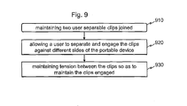
- Fig. 9 shows a method of an example embodiment, comprising: maintaining 910 two user separable clips joined; allowing 920 a user to separate and engage the clips against different sides of the portable device; and maintaining 930 tension between the clips so as to maintain the clips engaged.
- the maintaining 930 of the tension between the clips may be performed using a stretching band.
- the stretching band may be configured to slide through or around the accessory device when the user adjusts the positioning of the accessory device so as to allow lengthwise adjustment and to generate desired restraining force (e.g. due to friction and compression of the band).
- a technical effect of one or more of the example embodiments disclosed herein is that the apparatus may avoid leaving the accessory device unprotected from dust and scratches when not being used on the portable device.
- Another technical effect of one or more of the example embodiments disclosed herein is that an accessory device of rather simple construction can be easily and universally attached to different portable devices of various make and model without model specific adaptation.
- Yet another technical effect of one or more of the example embodiments disclosed herein is that the apparatus may avoid the need to run a rubber band or another loop around the portable device and thus the apparatus may avoid blocking or interfering a display or access to a touch screen or buttons when the accessory device is attached to the portable device.
- the apparatus may be readily used with both left-handed and right-handed users. Yet another technical effect of one or more of the example embodiments disclosed herein is that the apparatus may avoid the need for magnet based retention systems that may adversely affect on functioning of the portable device such as camera autofocus and electrical signaling due to electromagnetic self-induction that is likely to happen when bringing a strong magnet near electronic circuitries.
- the different functions discussed herein may be performed in a different order and/or concurrently with each other. Furthermore, if desired, one or more of the before-described functions may be optional or may be combined.
Landscapes
- Physics & Mathematics (AREA)
- General Physics & Mathematics (AREA)
- Engineering & Computer Science (AREA)
- Signal Processing (AREA)
- Telephone Set Structure (AREA)
- Studio Devices (AREA)
Abstract
Description
- The present application generally relates to portable device accessories.
- This section illustrates useful background information without admission of any technique described herein representative of the state of the art.
- Portable devices of different types are used in modern societies for various purposes such as communications, entertainment, imaging and navigation. Some devices can be further enhanced or their use be facilitated by physical accessories such as add-on lenses, replaceable color covers or even smart covers that provide a portable device, when attached, with new features or functionalities such as a near field communication circuitry or wireless charging capability.
- As the number of various items used by a person increases, it is increasingly more difficult to access at sudden need a given one. Therefore, different accessories are integrated with portable devices as much as possible. For example, some very high-end camera phone model contains a built-in neutral density (ND) filter that is automatically used in excessive ambient light to increase the exposure time when the optics would otherwise be too fast or when a longer exposure time would produce more pleasing effects in photographs.
- Various aspects of examples of the invention are set out in the claims.
- According to a first example aspect of the present invention there is provided an apparatus comprising:
- two user separable and joinable clips; and
- a retractable clip tensioner configured to enable a user to attach the apparatus against a side of a portable device by expanding and engaging the clips against different sides of the portable device so that the retractable clip tensioner maintains the clips engaged.
- The different sides may be opposite sides. The side of the portable device against which the apparatus is attached may reside between the different sides. The side of the portable device against which the apparatus is attached may be substantially perpendicular to at least one of the different sides. The side of the portable device against which the apparatus is attached may have substantially greater surface area than the different sides.
- The clips may be configured to collectively form, when joined, a storage space. The clips may be configured to cover the storage space on two opposite sides.
- The apparatus may be configured to cover an accessory device. The covering may be configured to provide a protected storage for the accessory device.
- The apparatus may further comprise an accessory device holder configured to mechanically inter-connect the accessory device with the retractable clip tensioner.
- The apparatus may further comprise the accessory device. The accessory device may be configured to co-operate with the portable device. At least one of the retractable clip tensioner and the accessory device may be configured to enable adjustable attachment of the accessory device to the retractable clip tensioner. The apparatus may further comprise the accessory device holder configured to enable adjustable attachment of the accessory device to the retractable clip tensioner.
- The clips may comprise a concave forms configured to sandwich the portable device when the clips are expanded and engaged against the different sides of the portable device. The clips may have a C or J shaped profile. The accessory device may be configured to form with the clips a closed exterior surface when the clips are joined and the accessory device is contained in the storage space. The clips may be configured to operate as clamps or hooks when engaged to the portable device.
- The retractable clip tensioner may comprise an elastic member. The elastic member may comprise one or more of: an elastic band; a spring; a string; a magnet; and a pressurized bag. The elastic member may comprise more than 50 % of its weight of any of: rubber; synthetic rubber; silicone rubber; and spring steel. The elastic member may comprise a stretching member. The stretching member may be length-adjustable.
- The retractable clip tensioner may be further configured to enable user adjustable positioning of the accessory device at different positions along the retractable clip tensioner. The retractable clip tensioner may be further configured to enable user adjustable positioning of the accessory device at different positions by sliding the accessory device along the retractable clip tensioner. The retractable clip tensioner may be further configured to inhibit free sliding of the clip tensioner. Free sliding may refer to sliding in normal use as function of gravity and accelerations invoked by normal use.
- The accessory device may comprise a functional part. The functional part may be configured to provide a new function or to facilitate the use of an existing function of the portable device. The functional part may be an add-on part. The functional part may be configured to co-operate with a camera lens of the portable device. The functional part may comprise one or more elements selected from a group consisting of: an objective; an optical filter; a neutral density filter; a gradient filter; a polarizing filter; a light guide configured to pass flash light; a mirror or prism configured to guide flash light; optically transparent gel configured to facilitate objective tilting; an objective cover; a sun glare protector; a touch screen stylus; a spare part for the retractable clip tensioner; an input device; and a joystick.
- The accessory device may be configured to enable attaching the functional part at adjustable distance from the portable device. The accessory device may be configured to hold the functional part in a user selectable orientation. The accessory device may be configured to be attachable to the portable device in a respectively user selectable orientation so that the distance of the functional part from the portable device is user adjustable by adjusting the orientation of the accessory device with respect to the portable device.
- The accessory device may comprise a user replaceable add-on parts. The accessory device may comprise storage positions for holding additional add-on parts.
- Any one or more of the clips may be formed of plastics; metal; composite material; glass; rubber; and any combination thereof. One or more of the clips may be transparent. One or more of the clips may be formed by molding. One or more of the clips may be formed by injection molding.
- One or more of the clips may be configured to leave a space for a key or button on the side of the portable device to avoid undesirably acting on the key or button when the clip is engaged against the side of the portable device at the key or button. Alternatively or additionally the apparatus may be configured to enable diagonal use of the retractable clip tensioner so as to enable a user to engage the clip against the side of the portable device at a position in which the key or button is not covered by the clip and to enable correct positioning of the accessory device by suitably positioning a clip on another side of the portable device. The clips may comprise a friction enhancing shape to inhibit sideways slipping. Alternatively or additionally, the clips may be shaped to wedge against the side of the portable device to inhibit sideways slipping.
- The apparatus may be configured to enable attaching the portable device to another object. The another object may be selected from a group consisting of: a camera cradle; a neck strap; a car cradle; and a table-top device holder.
- The apparatus may be configured to enable attaching the accessory device to a variety of different models of portable devices. The portable device may be freely selected from two or more devices of: mobile telephones; personal digital assistants; digital cameras; tablet computers; laptop computers; game devices; and navigation devices. The portable device may be a handheld device. The portable device may be a battery operated device. The portable device may be a wireless communication device.
- According to a second example aspect of the present invention, there is provided a system comprising the apparatus of the first example aspect and the portable device.
- According to a third example aspect of the present invention, there is provided a method comprising:
- maintaining two user separable clips joined;
- allowing a user to separate and engage the clips against different sides of the portable device; and
- maintaining tension between the clips so as to maintain the clips engaged.
- The method may further comprise holding an accessory device attached against the portable device.
- The method may further comprise enabling the user to adjust positioning of the accessory device against the portable device.
- The method may further comprise inhibiting free movement of the accessory device out of its adjusted position.
- The maintaining of the tension may be performed using a stretching band. The stretching band may be configured to slide through or around the accessory device when the user adjust the positioning of the accessory device so as to allow lengthwise adjustment and to generate desired restraining force (e.g. due to friction and compression of the band). According to a fourth example aspect of the present invention, there is provided an apparatus comprising:
- two user separable and joinable clip means; and
- means for retractable clip tensioning configured to enable a user to attach the apparatus against a side of a portable device by expanding and engaging the clip means against different sides of the portable device so that the means for retractable clip tensioning maintains the clips engaged.
- According to a fifth example aspect of the present invention, there is provided an apparatus comprising:
- means for maintaining two user separable clips joined;
- means for allowing a user to separate and engage the clips against different sides of the portable device; and
- means for maintaining tension between the clips so as to maintain the clips engaged.
- Different non-binding example aspects and embodiments of the present invention have been illustrated in the foregoing. The embodiments in the foregoing are used merely to explain selected aspects or steps that may be utilized in implementations of the present invention. Some embodiments may be presented only with reference to certain example aspects of the invention. It should be appreciated that corresponding embodiments may apply to other example aspects as well.
- For a more complete understanding of example embodiments of the present invention, reference is now made to the following descriptions taken in connection with the accompanying drawings in which:
-
Fig. 1 shows an illustration of an apparatus of an example embodiment of the invention in a compacted configuration; -
Fig. 2 shows an illustration of the apparatus ofFig. 1 in an expanded configuration; -
Figs. 3 and 4 illustrate the apparatus ofFigs. 1 and 2 in the expanded configuration when attached to a portable device and with different positioning of an accessory device against the portable device; -
Fig. 5 shows an illustration of a system of a first portable device and the apparatus ofFig. 1 , when seen diagonally from a rear-side of the first portable device; -
Fig. 6 shows an illustration of the system ofFig. 5 , when seen from a front-side of the first portable device; -
Fig. 7 shows an illustration of a top portion of the system ofFig. 5 , when seen from side of the first portable device; -
Fig. 8 shows an illustration of a system of a second portable device and the apparatus of -
Fig. 1 , when seen diagonally from a rear-side of the first portable device; and -
Fig. 9 shows a method of an example embodiment. - An example embodiment of the present invention and its potential advantages are understood by referring to
Figs. 1 through 9 of the drawings. In this document, like reference signs denote like parts or steps. -
Fig. 1 shows an illustration of anapparatus 100 of an example embodiment of the invention in a compacted configuration. Theapparatus 100 comprises two user separable andjoinable clips clips clips opposite sides -
Fig. 2 shows an illustration of theapparatus 100 ofFig. 1 in an open or expanded configuration in which theclips retractable clip tensioner 210 configured to enable a user to attach theapparatus 100 against a side of a portable device by separating and engaging the clips against different sides of the portable device so that the retractable clip tensioner maintains the clips engaged. -
Figs. 1 and 2 further show anaccessory device holder 130 configured to mechanically inter-connect an accessory device with theretractable clip tensioner 210. As shown inFigs. 1 and 2 , the different sides can be opposite sides. In another example embodiment with three or more clips, the different sides need not be opposite if e.g. the portable device has a triangular or pentagon shape. Moreover, as appears e.g. inFigs. 3 to 6 and8 , the side of the portable device against which the apparatus is attached may reside between the different sides against which the clips are engaged. Further, theseFigs. 3 to 6 and8 exemplify that the side of the portable device against which the apparatus is attached can be substantially perpendicular to at least one of the different sides. With rounded side shown in theseFigs. 3 to 6 and8 there may be no clear plane of the side in question, but one can consider, for understanding the perpendicularity of sides of the portable device, the direction of a side as its average plane as if the side were not rounded at all. Moreover, in an example embodiment, the side of the portable device against which the apparatus is attached has substantially greater surface area than the different sides. -
Figs. 3 and 4 illustrate the apparatus ofFigs. 1 and 2 in the expanded configuration when attached to a firstportable device 310 and with different positioning of anaccessory device 320 against the portable device.Figs. 3 and 4 show the first portable device only partially in sake of simplicity, whileFigs. 5 and 6 provide further views with the entire first portable 310 device drawn.Figs. 3 also shows by a dashed line how an elastic loop is connected to theclips - In an example embodiment, the accessory device is configured to co-operate with the portable device. In an example embodiment, at least one of the retractable clip tensioner and the accessory device is configured to enable adjustable attachment of the accessory device to the retractable clip tensioner. For example, the accessory device can be adjustably attached to the retractable clip tensioner by forming a loop in only one leg of the
elastic band loop 210 shown inFig. 1 directly around the accessory device and by sliding the loop in theclips Figs. 1 to 5 and7 illustrate another implementation in which theaccessory device holder 130 is provided to hold theaccessory device 320 and to adjustably attach theaccessory device 320 against the portable device. - In an example embodiment, the
clips clips clips 110, 120 a closed exterior surface when theclips - In an example embodiment, the
retractable clip tensioner 210 comprises an elastic member. The elastic member comprises e.g. one or more of: an elastic band; a spring; a string; a magnet; and a gas compression based resilient element (e.g. pressurized bag or piece of foam configured to resiliently pass tension between engaging surfaces of the clips 110,120). In an example embodiment, the elastic member comprises more than 50 % of its weight of any of: rubber; synthetic rubber; silicone rubber; and spring steel. In an example embodiment, the elastic member comprises a stretching member. In an example embodiment, the stretching member is length-adjustable. - The
retractable clip tensioner 210 can be further configured to enable user adjustable positioning of theaccessory device 320 at different positions along theretractable clip tensioner 210. In an example embodiment, theretractable clip tensioner 210 is configured to enable user adjustable positioning of the accessory device at different positions by sliding the accessory device along theretractable clip tensioner 210. For example, theaccessory device holder 130 can be moved linearly around the stretchable band and the band be configured to compress the accessory device by its sides. To this end, theaccessory device holder 130 can be provided with suitable stretchable band conducting members such as channels along both sides of theaccessory device holder 130. This way adjustability and holding force for theaccessory device holder 130 can be produced such that compatibility is attained with many types of accessory devices and portable devices. - In an example embodiment, the
retractable clip tensioner 210 is further configured to inhibit free sliding of the accessory device along theclip tensioner 210. Free sliding may refer to sliding in normal use as function of gravity and accelerations invoked by normal use. - In an example embodiment, the accessory device comprises a functional part. The functional part can be configured to provide a new function or to facilitate the use of an existing function of the portable device. The functional part can be an add-on part. In an example embodiment, the functional part is configured to co-operate with a camera lens of the portable device. In an example embodiment, the functional part comprises one or more elements selected from a group consisting of: an objective; an optical filter; a neutral density filter; a gradient filter; a polarizing filter; a light guide for passing flash light; a mirror or prism for guiding flash light; optically transparent gel for facilitating objective tilting; an objective cover; a sun glare protector; a touch screen stylus; an input device such as a joystick and a spare part for the retractable clip tensioner.
- It should be appreciated that while only one display is drawn in
Figs. 5 and 6 , for example, theapparatus 100 ofFig. 1 can also be used with a portable device having a plurality of displays on one or more sides. Moreover, more than oneapparatus 100 ofFig. 1 can be simultaneously used. - In an example embodiment, the accessory device is configured to enable attaching the functional part at adjustable distance from the portable device. The accessory device can be configured to hold the functional part in a user selectable orientation. For example, the accessory device can be configured to be attachable to the portable device in a respectively user selectable orientation so that the distance of the functional part from the portable device is user adjustable by adjusting the orientation of the accessory device with respect to the portable device.
- In an example embodiment, the
apparatus 100 further comprises theaccessory device 320. In an example embodiment, theapparatus 100 further comprises a plurality ofaccessory devices 320. In an example embodiment, theapparatus 100 further comprises one or more accessory device storage positions. The storage positions can be formed, for example, in any one or more of:clip 110;clip 120; and theaccessory device holder 130. - In an example embodiment, any one or more of the
clips clips - In an example embodiment, one or more of the
clips portable device 310 as shown inFigs. 6 and 7 : there are buttons that slightly protrude from a side of the firstportable device 310 and theclip 110 has a corresponding groove or recess to avoid engaging with such a button. Alternatively or additionally theapparatus 100 can be configured to enable diagonal use of theretractable clip tensioner 210 so as to enable a user to engage the clip against the side of the portable device at a position in which the key or button is not covered by the clip and to enable correct positioning of the accessory device by suitably positioning a clip on another side of the portable device. For example, looking atFig. 6 , the clip 11 could be slightly offset to the right-hand direction in between the entirely visible centrally positioned button and the button that is nearly concealed by theclip 110. In compensation, the clip on the bottom could be suitably offset to left-hand side direction so that the accessory device would settle and be securely held at desired position against the firstportable device 310. - In an example embodiment, the clips comprise a friction enhancing shape to inhibit sideways slipping. For example, the clips can be shaped to wedge against the side of the portable device to inhibit sideways slipping. For example,
Fig. 7 illustrates how theclip 110 would wedge against the edge of the firstportable device 310 because of the mutual shapes of the edge and of theclip 310. - In an example embodiment, the
apparatus 100 is configured to enable attaching the portable device to another object e.g. using aloop 330 formed in theclip 110. The another object can be selected, for example, from a group consisting of: a camera cradle; a neck strap; a car cradle; and a table-top device holder. -
Fig. 8 shows theapparatus 100 attached to another type of camera equipped mobile phone (second portable device 810). The secondportable device 810 has a slightly protruding area at a region of its built-in camera. Such a design is sometimes used to enable building a thin device with high-quality objective that has optical image stabilization. However, it is apparent that such design would also make it difficult to engage an accessory device such as an add-on objective or filter solely with rigid parts. Thanks to the flexible nature of the apparatus ofFig. 1 , the slight protrusion only enhances the attachment of the accessory device against the second portable device. - Different embodiments of the present invention find a wide range of possible applications. For example, the portable device can be freely selected from two or more devices of: mobile telephones; personal digital assistants; digital cameras; tablet computers; laptop computers; game devices; and navigation devices. In an example embodiment, the portable device is a handheld device. The portable device can be a battery operated device and / or a wireless communication device.
-
Fig. 9 shows a method of an example embodiment, comprising: maintaining 910 two user separable clips joined; allowing 920 a user to separate and engage the clips against different sides of the portable device; and maintaining 930 tension between the clips so as to maintain the clips engaged. - The maintaining 930 of the tension between the clips may be performed using a stretching band. The stretching band may be configured to slide through or around the accessory device when the user adjusts the positioning of the accessory device so as to allow lengthwise adjustment and to generate desired restraining force (e.g. due to friction and compression of the band).
- Without in any way limiting the scope, interpretation, or application of the claims appearing below, a technical effect of one or more of the example embodiments disclosed herein is that the apparatus may avoid leaving the accessory device unprotected from dust and scratches when not being used on the portable device. Another technical effect of one or more of the example embodiments disclosed herein is that an accessory device of rather simple construction can be easily and universally attached to different portable devices of various make and model without model specific adaptation. Yet another technical effect of one or more of the example embodiments disclosed herein is that the apparatus may avoid the need to run a rubber band or another loop around the portable device and thus the apparatus may avoid blocking or interfering a display or access to a touch screen or buttons when the accessory device is attached to the portable device. Yet another technical effect of one or more of the example embodiments disclosed herein is that the apparatus may be readily used with both left-handed and right-handed users. Yet another technical effect of one or more of the example embodiments disclosed herein is that the apparatus may avoid the need for magnet based retention systems that may adversely affect on functioning of the portable device such as camera autofocus and electrical signaling due to electromagnetic self-induction that is likely to happen when bringing a strong magnet near electronic circuitries.
- If desired, the different functions discussed herein may be performed in a different order and/or concurrently with each other. Furthermore, if desired, one or more of the before-described functions may be optional or may be combined.
- Although various aspects of the invention are set out in the independent claims, other aspects of the invention comprise other combinations of features from the described embodiments and/or the dependent claims with the features of the independent claims, and not solely the combinations explicitly set out in the claims.
- It is also noted herein that while the foregoing describes example embodiments of the invention, these descriptions should not be viewed in a limiting sense. Rather, there are several variations and modifications which may be made without departing from the scope of the present invention as defined in the appended claims.
Claims (15)
- An apparatus comprising:two user separable and joinable clips; anda retractable clip tensioner configured to enable a user to attach the apparatus against a side of a portable device by expanding and engaging the clips against different sides of the portable device so that the retractable clip tensioner maintains the clips engaged.
- The apparatus of claim 1, wherein the clips are configured to collectively form, when joined, a storage space for an accessory device.
- The apparatus of claim 2, wherein the accessory device is configured to form with the clips a closed exterior surface when the clips are joined and the accessory device is contained in the storage space.
- The apparatus of claim 1, further comprising an accessory device holder configured to mechanically inter-connect the accessory device with the retractable clip tensioner.
- The apparatus of claim 4, wherein the accessory device holder is further configured to enable adjustable attachment of the accessory device to the retractable clip tensioner.
- The apparatus of claim 1, further comprising the accessory device.
- The apparatus of claim 6, wherein the accessory device is configured to co-operate with the portable device.
- The apparatus of claim 1, wherein at least one of the retractable clip tensioner and the accessory device is configured to enable adjustable attachment of the accessory device to the retractable clip tensioner.
- The apparatus of claim 1, wherein the clips comprise concave forms configured to sandwich the portable device when the clips are separated and engaged against the different sides of the portable device.
- The apparatus of claim 1, wherein the retractable clip tensioner comprises an elastic band.
- The apparatus of claim 1, further configured to enable user adjustable positioning of the accessory device at different positions of the retractable clip tensioner.
- The apparatus of claim 1, wherein the accessory device comprises one or more items selected from a group consisting of: an objective; an optical filter; a neutral density filter; a gradient filter; a polarizing filter; a light guide for passing flash light; a mirror or prism for guiding flash light; optically transparent gel for facilitating objective tilting; an objective cover; a sun glare protector; a touch screen stylus; a spare part for the retractable clip tensioner; an input device; and a joystick.
- The apparatus of claim 1, further configured to enable attaching the accessory device at adjustable distance from the portable device.
- The apparatus of claim 4, wherein the accessory device holder comprises one or more user replaceable accessory devices.
- The apparatus of claim 1, wherein any one or more of the clips is formed of plastics; metal; composite material; glass; rubber; and any combination thereof.
Applications Claiming Priority (1)
| Application Number | Priority Date | Filing Date | Title |
|---|---|---|---|
| US14/188,745 US9883016B2 (en) | 2014-02-25 | 2014-02-25 | Method and apparatus for portable device accessories |
Publications (1)
| Publication Number | Publication Date |
|---|---|
| EP2911001A1 true EP2911001A1 (en) | 2015-08-26 |
Family
ID=52807515
Family Applications (1)
| Application Number | Title | Priority Date | Filing Date |
|---|---|---|---|
| EP15155676.8A Withdrawn EP2911001A1 (en) | 2014-02-25 | 2015-02-19 | Apparatus for portable device accessories |
Country Status (2)
| Country | Link |
|---|---|
| US (1) | US9883016B2 (en) |
| EP (1) | EP2911001A1 (en) |
Families Citing this family (6)
| Publication number | Priority date | Publication date | Assignee | Title |
|---|---|---|---|---|
| WO2018075988A1 (en) * | 2016-10-21 | 2018-04-26 | Hoey Thomas Joseph | Article retaining device and method of attachment |
| US10242606B1 (en) * | 2017-11-28 | 2019-03-26 | Tyler Jeffrey | Novelty item for cameras |
| US11079660B2 (en) | 2019-04-05 | 2021-08-03 | Noah Systems, Llc | Optical filter holder |
| USD905785S1 (en) | 2019-04-05 | 2020-12-22 | Noah Systems, Llc | Optical filter holder |
| USD905784S1 (en) | 2019-04-05 | 2020-12-22 | Noah Systems, Llc | Camera lens adapter |
| US20210140580A1 (en) * | 2019-11-08 | 2021-05-13 | Popsockets Llc | Accessory attachment for a portable electronic device |
Citations (4)
| Publication number | Priority date | Publication date | Assignee | Title |
|---|---|---|---|---|
| CA2230360A1 (en) * | 1997-03-07 | 1998-09-07 | Miwa Shimizu | General-purpose photo filter unit |
| JP2002368854A (en) * | 2001-06-07 | 2002-12-20 | Katsuo Takahashi | Display magnification device for mobile phone |
| GB2409050A (en) * | 2003-12-13 | 2005-06-15 | Max Edward Hawkins | Mobile phone lens cap with straps |
| US20130298313A1 (en) * | 2012-05-09 | 2013-11-14 | Gilda Teresa MAck | Mini undergarment attachments used by women to help hold up pants and skirts that have no belt loop. |
Family Cites Families (18)
| Publication number | Priority date | Publication date | Assignee | Title |
|---|---|---|---|---|
| US1855345A (en) * | 1928-07-20 | 1932-04-26 | Alma M Fischer | Shoe strap |
| US1736220A (en) * | 1928-09-06 | 1929-11-19 | Dolphus E Robertson | Camera attachment |
| US3283433A (en) * | 1964-06-03 | 1966-11-08 | Nicholas A Navarino | Seat reservation marker device |
| US4133080A (en) * | 1974-11-04 | 1979-01-09 | John Kuk | Textbook holder |
| US3961349A (en) * | 1974-12-16 | 1976-06-01 | Polaroid Corporation | Accessory mounting adaptor for photographic apparatus |
| US4666274A (en) * | 1984-10-05 | 1987-05-19 | Canon Kabushiki Kaisha | Waterproof camera |
| US5805944A (en) * | 1997-03-13 | 1998-09-08 | Eastman Kodak Company | Alternative camera carry-strap and lens cap |
| US6151172A (en) * | 1999-11-08 | 2000-11-21 | Ferraro; John C | Power lens |
| US6275333B1 (en) * | 2000-01-25 | 2001-08-14 | Wendy E Shaffer | Display window magnification device |
| US20090181729A1 (en) | 2008-01-04 | 2009-07-16 | Griffin Jr Paul P | Device case with optical lenses |
| US8646736B2 (en) * | 2010-07-21 | 2014-02-11 | James Berry | Holding device for an electronic device |
| US8424825B2 (en) * | 2011-03-16 | 2013-04-23 | Eddie Somuah | Adjustable holder for electronic devices |
| US20120246879A1 (en) * | 2011-03-29 | 2012-10-04 | Mark Pestal | Retainer Apparatus |
| US8385004B2 (en) * | 2011-07-28 | 2013-02-26 | Muses Consolidated | Accessory for portable imaging device |
| CN103096655A (en) | 2011-10-31 | 2013-05-08 | 深圳富泰宏精密工业有限公司 | Fixed structure of outer-mounted lens and portable electronic device with same |
| CN202533640U (en) | 2012-03-13 | 2012-11-14 | 李建成 | External lens device of mobile phone |
| US9468308B2 (en) * | 2013-07-18 | 2016-10-18 | Eclips Global 2015 Incorporated | Springless double ended elastic fabric tensioner |
| US20150028071A1 (en) * | 2013-07-23 | 2015-01-29 | Ismael Brillon, JR. | Multi-smartphone grabbing device with attachable wallet |
-
2014
- 2014-02-25 US US14/188,745 patent/US9883016B2/en active Active
-
2015
- 2015-02-19 EP EP15155676.8A patent/EP2911001A1/en not_active Withdrawn
Patent Citations (4)
| Publication number | Priority date | Publication date | Assignee | Title |
|---|---|---|---|---|
| CA2230360A1 (en) * | 1997-03-07 | 1998-09-07 | Miwa Shimizu | General-purpose photo filter unit |
| JP2002368854A (en) * | 2001-06-07 | 2002-12-20 | Katsuo Takahashi | Display magnification device for mobile phone |
| GB2409050A (en) * | 2003-12-13 | 2005-06-15 | Max Edward Hawkins | Mobile phone lens cap with straps |
| US20130298313A1 (en) * | 2012-05-09 | 2013-11-14 | Gilda Teresa MAck | Mini undergarment attachments used by women to help hold up pants and skirts that have no belt loop. |
Also Published As
| Publication number | Publication date |
|---|---|
| US20150237994A1 (en) | 2015-08-27 |
| US9883016B2 (en) | 2018-01-30 |
Similar Documents
| Publication | Publication Date | Title |
|---|---|---|
| US9883016B2 (en) | Method and apparatus for portable device accessories | |
| US10694837B1 (en) | Magnetically configurable strap accessory for a mobile communications device | |
| US8162283B1 (en) | Stand for supporting a portable electronic device | |
| US8798453B2 (en) | Attachment for a personal communication device | |
| US9306612B2 (en) | Mobile electronic device holder | |
| US9408446B2 (en) | Case for a portable electronic device | |
| KR101421220B1 (en) | Case for portable electronic device having flexible display | |
| US20130177304A1 (en) | Portable electronic device case accessory with interchangeable camera lens system | |
| US20160007705A1 (en) | Case for a Portable Electronic Device | |
| US20140268376A1 (en) | Optical systems for mobile electronic devices | |
| US20140076748A1 (en) | Device for storing tablet computer and support the same in at least two erected/standing positions | |
| WO2013009524A2 (en) | System for handheld portable electronic devices | |
| KR20160018306A (en) | Cover for portable electronic device | |
| KR101461004B1 (en) | Side-touch enabled smartphone case | |
| CN101236349A (en) | Device for replacing lens of mobile device | |
| JP5711414B1 (en) | Information terminal storage case | |
| KR200473012Y1 (en) | Cellular phone case | |
| US20240389742A1 (en) | Tactical accessory holder | |
| KR101925080B1 (en) | Functional mobile holder | |
| KR200472146Y1 (en) | Protecting Case with Application which Capable of being Attached and Detached | |
| US8970794B2 (en) | Portable video enhancement apparatus | |
| KR200353853Y1 (en) | The magnifier apparatus for display of cellular phone in moveable type | |
| US9393914B2 (en) | Efficient holder for mobile devices | |
| KR101310934B1 (en) | Protective device for portable terminal with keyboard | |
| JP3213759U (en) | Cell phone terminal with spectacle case, cover for cell phone terminal with spectacle case, and spectacle case |
Legal Events
| Date | Code | Title | Description |
|---|---|---|---|
| PUAI | Public reference made under article 153(3) epc to a published international application that has entered the european phase |
Free format text: ORIGINAL CODE: 0009012 |
|
| AK | Designated contracting states |
Kind code of ref document: A1 Designated state(s): AL AT BE BG CH CY CZ DE DK EE ES FI FR GB GR HR HU IE IS IT LI LT LU LV MC MK MT NL NO PL PT RO RS SE SI SK SM TR |
|
| AX | Request for extension of the european patent |
Extension state: BA ME |
|
| 17P | Request for examination filed |
Effective date: 20151229 |
|
| RBV | Designated contracting states (corrected) |
Designated state(s): AL AT BE BG CH CY CZ DE DK EE ES FI FR GB GR HR HU IE IS IT LI LT LU LV MC MK MT NL NO PL PT RO RS SE SI SK SM TR |
|
| STAA | Information on the status of an ep patent application or granted ep patent |
Free format text: STATUS: THE APPLICATION HAS BEEN WITHDRAWN |
|
| 18W | Application withdrawn |
Effective date: 20171207 |