EP2910781B1 - Solar thermal power system - Google Patents
Solar thermal power system Download PDFInfo
- Publication number
- EP2910781B1 EP2910781B1 EP14156348.6A EP14156348A EP2910781B1 EP 2910781 B1 EP2910781 B1 EP 2910781B1 EP 14156348 A EP14156348 A EP 14156348A EP 2910781 B1 EP2910781 B1 EP 2910781B1
- Authority
- EP
- European Patent Office
- Prior art keywords
- section
- thermal energy
- steam
- energy storage
- economizer
- Prior art date
- Legal status (The legal status is an assumption and is not a legal conclusion. Google has not performed a legal analysis and makes no representation as to the accuracy of the status listed.)
- Active
Links
- 238000003860 storage Methods 0.000 claims description 57
- 239000012530 fluid Substances 0.000 claims description 50
- 238000004146 energy storage Methods 0.000 claims description 30
- XLYOFNOQVPJJNP-UHFFFAOYSA-N water Substances O XLYOFNOQVPJJNP-UHFFFAOYSA-N 0.000 claims description 25
- 238000000034 method Methods 0.000 claims description 10
- 230000008014 freezing Effects 0.000 claims description 8
- 238000007710 freezing Methods 0.000 claims description 8
- 230000003134 recirculating effect Effects 0.000 claims 2
- 238000003303 reheating Methods 0.000 claims 1
- 150000003839 salts Chemical class 0.000 description 29
- 230000005611 electricity Effects 0.000 description 5
- 238000001704 evaporation Methods 0.000 description 5
- 230000008020 evaporation Effects 0.000 description 4
- 230000007423 decrease Effects 0.000 description 3
- 230000003247 decreasing effect Effects 0.000 description 3
- 238000005516 engineering process Methods 0.000 description 3
- FGIUAXJPYTZDNR-UHFFFAOYSA-N potassium nitrate Chemical class [K+].[O-][N+]([O-])=O FGIUAXJPYTZDNR-UHFFFAOYSA-N 0.000 description 3
- 238000010586 diagram Methods 0.000 description 2
- 230000000694 effects Effects 0.000 description 2
- 230000014759 maintenance of location Effects 0.000 description 2
- 239000000203 mixture Substances 0.000 description 2
- VWDWKYIASSYTQR-UHFFFAOYSA-N sodium nitrate Chemical compound [Na+].[O-][N+]([O-])=O VWDWKYIASSYTQR-UHFFFAOYSA-N 0.000 description 2
- DGAQECJNVWCQMB-PUAWFVPOSA-M Ilexoside XXIX Chemical compound C[C@@H]1CC[C@@]2(CC[C@@]3(C(=CC[C@H]4[C@]3(CC[C@@H]5[C@@]4(CC[C@@H](C5(C)C)OS(=O)(=O)[O-])C)C)[C@@H]2[C@]1(C)O)C)C(=O)O[C@H]6[C@@H]([C@H]([C@@H]([C@H](O6)CO)O)O)O.[Na+] DGAQECJNVWCQMB-PUAWFVPOSA-M 0.000 description 1
- 230000002730 additional effect Effects 0.000 description 1
- 230000004075 alteration Effects 0.000 description 1
- 238000006243 chemical reaction Methods 0.000 description 1
- 238000010276 construction Methods 0.000 description 1
- 238000010438 heat treatment Methods 0.000 description 1
- 229910001338 liquidmetal Inorganic materials 0.000 description 1
- 235000010333 potassium nitrate Nutrition 0.000 description 1
- 238000000926 separation method Methods 0.000 description 1
- 229910052708 sodium Inorganic materials 0.000 description 1
- 239000011734 sodium Substances 0.000 description 1
- 235000010344 sodium nitrate Nutrition 0.000 description 1
- 238000011144 upstream manufacturing Methods 0.000 description 1
Images


Classifications
-
- F—MECHANICAL ENGINEERING; LIGHTING; HEATING; WEAPONS; BLASTING
- F03—MACHINES OR ENGINES FOR LIQUIDS; WIND, SPRING, OR WEIGHT MOTORS; PRODUCING MECHANICAL POWER OR A REACTIVE PROPULSIVE THRUST, NOT OTHERWISE PROVIDED FOR
- F03G—SPRING, WEIGHT, INERTIA OR LIKE MOTORS; MECHANICAL-POWER PRODUCING DEVICES OR MECHANISMS, NOT OTHERWISE PROVIDED FOR OR USING ENERGY SOURCES NOT OTHERWISE PROVIDED FOR
- F03G6/00—Devices for producing mechanical power from solar energy
- F03G6/003—Devices for producing mechanical power from solar energy having a Rankine cycle
-
- F—MECHANICAL ENGINEERING; LIGHTING; HEATING; WEAPONS; BLASTING
- F01—MACHINES OR ENGINES IN GENERAL; ENGINE PLANTS IN GENERAL; STEAM ENGINES
- F01K—STEAM ENGINE PLANTS; STEAM ACCUMULATORS; ENGINE PLANTS NOT OTHERWISE PROVIDED FOR; ENGINES USING SPECIAL WORKING FLUIDS OR CYCLES
- F01K1/00—Steam accumulators
- F01K1/12—Multiple accumulators; Charging, discharging or control specially adapted therefor
- F01K1/14—Circulation
-
- F—MECHANICAL ENGINEERING; LIGHTING; HEATING; WEAPONS; BLASTING
- F01—MACHINES OR ENGINES IN GENERAL; ENGINE PLANTS IN GENERAL; STEAM ENGINES
- F01K—STEAM ENGINE PLANTS; STEAM ACCUMULATORS; ENGINE PLANTS NOT OTHERWISE PROVIDED FOR; ENGINES USING SPECIAL WORKING FLUIDS OR CYCLES
- F01K13/00—General layout or general methods of operation of complete plants
- F01K13/02—Controlling, e.g. stopping or starting
-
- F—MECHANICAL ENGINEERING; LIGHTING; HEATING; WEAPONS; BLASTING
- F03—MACHINES OR ENGINES FOR LIQUIDS; WIND, SPRING, OR WEIGHT MOTORS; PRODUCING MECHANICAL POWER OR A REACTIVE PROPULSIVE THRUST, NOT OTHERWISE PROVIDED FOR
- F03G—SPRING, WEIGHT, INERTIA OR LIKE MOTORS; MECHANICAL-POWER PRODUCING DEVICES OR MECHANISMS, NOT OTHERWISE PROVIDED FOR OR USING ENERGY SOURCES NOT OTHERWISE PROVIDED FOR
- F03G6/00—Devices for producing mechanical power from solar energy
- F03G6/06—Devices for producing mechanical power from solar energy with solar energy concentrating means
- F03G6/065—Devices for producing mechanical power from solar energy with solar energy concentrating means having a Rankine cycle
- F03G6/067—Binary cycle plants where the fluid from the solar collector heats the working fluid via a heat exchanger
-
- F—MECHANICAL ENGINEERING; LIGHTING; HEATING; WEAPONS; BLASTING
- F22—STEAM GENERATION
- F22B—METHODS OF STEAM GENERATION; STEAM BOILERS
- F22B1/00—Methods of steam generation characterised by form of heating method
- F22B1/006—Methods of steam generation characterised by form of heating method using solar heat
-
- F—MECHANICAL ENGINEERING; LIGHTING; HEATING; WEAPONS; BLASTING
- F22—STEAM GENERATION
- F22D—PREHEATING, OR ACCUMULATING PREHEATED, FEED-WATER FOR STEAM GENERATION; FEED-WATER SUPPLY FOR STEAM GENERATION; CONTROLLING WATER LEVEL FOR STEAM GENERATION; AUXILIARY DEVICES FOR PROMOTING WATER CIRCULATION WITHIN STEAM BOILERS
- F22D1/00—Feed-water heaters, i.e. economisers or like preheaters
-
- Y—GENERAL TAGGING OF NEW TECHNOLOGICAL DEVELOPMENTS; GENERAL TAGGING OF CROSS-SECTIONAL TECHNOLOGIES SPANNING OVER SEVERAL SECTIONS OF THE IPC; TECHNICAL SUBJECTS COVERED BY FORMER USPC CROSS-REFERENCE ART COLLECTIONS [XRACs] AND DIGESTS
- Y02—TECHNOLOGIES OR APPLICATIONS FOR MITIGATION OR ADAPTATION AGAINST CLIMATE CHANGE
- Y02E—REDUCTION OF GREENHOUSE GAS [GHG] EMISSIONS, RELATED TO ENERGY GENERATION, TRANSMISSION OR DISTRIBUTION
- Y02E10/00—Energy generation through renewable energy sources
- Y02E10/40—Solar thermal energy, e.g. solar towers
- Y02E10/46—Conversion of thermal power into mechanical power, e.g. Rankine, Stirling or solar thermal engines
Definitions
- the present disclosure generally relates to the field of concentrated solar power, and more particularly, to a concentrated solar thermal power plant with thermal energy storage fluid that utilizes concentrated solar power to store heat energy, and utilize the stored heat energy to generate electricity.
- a solar thermal power plant based on Direct Steam Central Receiver includes a large field of heliostats and a solar receiver placed on a tower of substantial height.
- the heliostats focus direct sunlight on to the solar receiver to produce steam to be utilized to run a steam turbine from producing electricity.
- the solar thermal power plant operates on a daily cycle, during clear sunlight hours, while shutting down in nights or in cloudy seasons.
- the solar thermal power plant is to meet increasing electricity demand, it needs to be operable irrespective of the availability of solar light, i.e. in nights or in cloudy seasons.
- a realization of such a solar thermal power plant generates a requirement of storing solar thermal energy during day times and utilizing thereto in nights or in cloudy seasons.
- a central receiver including a solar energy storage fluid, such as molten salt is generally used.
- the central receiver with molten salt is generally known as Molten Salt Central Receiver (MSCR).
- a MSCR, hot and cold storage tanks and a Molten Salt Steam Generator (MSSG) cycle are arranged to utilize the solar energy to produce electricity.
- the molten salt fluid heated at the MSCR is stored in the hot storage tank, at temperature of about 565°C, and after thermal energy thereof is being utilized by the MSSG cycle, it is stored in the cold storage tank, at temperature of about 290°C, from where it is further sent to the MSCR to be reheated.
- the MSSG cycle includes: a steam generator arrangement generally having an economizer, an evaporator and a superheater configured together; a reheat and a multi-stage turbine.
- the steam generator arrangement utilizes the heat of the hot molten salt and converts feedwater from a feedwater tank in to steam and send it to the multi-stage turbine for the conversion of heat to electricity through a generator. Further, the steam may be reheated in the reheater utilizing the hot molten salt to supply reheated steam for further stage of the multi-stage turbine.
- Various steam generator technologies may be applied as such for the said purpose.
- the economizer, evaporator and superheater may be separated in dedicated components or all the three sections may be combined in one single component (known as once-through steam generator).
- the evaporator may include one body (often referred to as kettle boiler) or divided into an evaporator and a steam drum for steam separation.
- each section like the economizer, evaporator and superheater may be divided into multiple bodies, in series or in parallel.
- the pressure of steam in the MSSG cycle are generally limited by a so-called pinch limitation in the MSSG cycle, typically at or lower than 115 bars.
- the pinch limitation in the MSSG is determined by two important factors. Firstly, feedwater temperature shall need to be maintained above a minimum level, typically 240°C, to eliminate the risk of freezing of the molten salt inside of a heat exchanger (economizer, evaporator, superheater (and if included reheat), may be simply be referred to as 'heat exchange'). Secondly, the temperature of the molten salt leaving the MSSG shall be kept as low as possibly allowed for safe operation of the salt, typically at 290°C.
- DE 10 2010 041903 A1 discloses a continuous flow steam generator including a vessel with a heat transfer medium inlet and a heat transfer medium outlet provided.
- a heat transfer medium channel is formed between the heat transfer medium inlet and the heat transfer medium outlet, and a heat transfer medium flows in the channel, having steam generator tubes disposed in the heat transfer medium channel, wherein a first portion of the steam generator tubes, and a second portion of the steam generator tubes is designed as a system of preheating and boiler tubes, and the first portion is disposed upstream of the second portion in the flow direction of the heat transfer medium.
- the present disclosure discloses a solar thermal power system that will be presented in the following simplified summary to provide a basic understanding of one or more aspects of the disclosure that are intended to overcome the discussed drawbacks, but to include all advantages thereof, along with providing some additional advantages.
- This summary is not an extensive overview of the disclosure. It is intended to neither identify key or critical elements of the disclosure, nor to delineate the scope of the present disclosure. Rather, the sole purpose of this summary is to present some concepts of the disclosure, its aspects and advantages in a simplified form as a prelude to the more detailed description that is presented hereinafter.
- An object of the present disclosure is to describe a solar thermal power system that is capable of increasing steam pressure in a steam generator arrangement while preventing freezing of the molten salt improving the efficiency of solar thermal power system.
- the solar thermal power system includes: a solar receiver, a thermal energy storage arrangement, a multistage steam turbine, a steam generator arrangement and a recirculation line.
- the thermal energy storage arrangement has thermal energy storage fluid to be circulated through the solar receiver to store thermal energy.
- the multistage steam turbine is configured to be operable on variable pressure steam generated from water supplied from a feedwater supply by utilizing the thermal energy storage fluid.
- the steam generator arrangement includes an economizer section, an evaporator section, and a superheater section communicably configured to utilize the heat of the hot thermal energy storage fluid at an entrance of the evaporator section to generate and supply the variable pressure steam to the superheater section and eventually to the multistage steam turbine.
- the recirculation line is configured around the economizer section to recirculate the heated water to an inlet of the economizer section to increase heat load on the economizer section in turn increasing pressure range of the variable pressure steam in the steam generator arrangement, while maintaining the temperature of the thermal energy storage fluid at an inlet of the evaporator section and at an outlet of the economizer section, and the feedwater temperature to the economizer section at desired values.
- the recirculation line includes a pump to overcome the pressure drop from the outlet to the inlet of the economizer section. The increase of steam pressure increases efficiency of the power cycle, specifically 'Rankine power cycle'.
- the recirculation line is configured from an outlet of the economizer section to the inlet of the economizer section. In another embodiment, the recirculation line is configured from the evaporator section to the inlet of the economizer section. In further embodiment, the economizer section may include a steam drum, and in that embodiment the recirculation line may be configured from the steam drum to the inlet of the economizer section.
- the solar thermal power system may further include a bypass line configured to bypass the economizer section to directly supply the water from the feedwater supply to the evaporator section.
- the solar thermal power system in one embodiment may also include a reheat assembly configured to the steam generator arrangement to reheat the steam.
- the thermal energy storage arrangement of the solar thermal power system includes first and second storage tanks.
- the first storage tank is adapted to store the hot thermal energy storage fluid.
- the second storage tank is adapted to store the cold thermal energy storage fluid.
- the thermal energy storage arrangement supplies the cold thermal energy storage fluid from the second storage tank to the solar receiver to be reheated.
- the solar thermal power system 100 (hereinafter referred to as 'system 100') includes a solar receiver 110 that may be placed on a tower 112 of substantial height and surrounded by a large field of heliostats 114.
- the solar receiver 110 receives solar energy from the heliostats 114 to be heated, which is designed to direct the solar energy from the sun 'S'.
- the system 100 further includes a thermal energy storage arrangement 120 (hereinafter referred to as 'thermal storage arrangement 120') (dotted lines) having a thermal energy storage fluid (hereinafter 'thermal storage fluid') to be circulated through the solar receiver 110 to store thermal energy therein.
- the thermal storage fluid may generally be a molten salt, a mixture of Sodium and Potassium Nitrates (NaNO 3 and KNO 3 ).
- any other thermal storage fluid such as other salt or liquid metal compositions, may be used as found suitable for the said purpose.
- the thermal storage arrangement 120 may include first and second storages tanks 122, 124.
- the thermal storage fluid flowing there through is heated.
- the heated thermal storage fluid may, from the solar receiver 110, is supplied and stored in the first storage tank 122. While at nights, the stored heated thermal storage fluid in the first storage thank 122 is utilized to generate electrical power, and resultant cold thermal storage fluid may be supplied to be stored in the second storage tank 124. Further during times, the cold thermal storage fluid from the second storage tank 124 is supplied the solar receiver 110 to be reheated.
- the system 100 further includes a multistage steam turbine 130, and a steam generator arrangement 140 to utilize heat of the thermal storage fluid of the thermal storage arrangement 120 for driving an electrical generator 150 to produce electrical power.
- the multistage steam turbine 130 may include a high pressure steam turbine 132, an intermediate pressure turbine 134 and a low pressure turbine 136, which may be adapted to be operable on a variable pressure steam generated by the steam generator arrangement 140, by utilizing the thermal storage fluid from the thermal storage arrangement 120.
- the steam generator arrangement 140 may receive water from a feedwater supply 116 via a pump at high pressure to generate and supply the variable pressure steam to the multistage steam turbine 130.
- the high pressure feedwater is primarily converted into high pressure steam of desired pressure, preferably of 170 bars, and temperature of 545°C, by the thermal storage fluid from the thermal storage arrangement 120.
- desired pressure preferably of 170 bars
- temperature preferably of 545°C
- thermal storage fluid from the thermal storage arrangement 120.
- the steam generator arrangement 140 (boundary by dotted lines) includes an economizer section 142, an evaporator section 144 and a superheater section 148 communicably configured to utilize the heat of the hot thermal storage fluid, at an entrance of the evaporator section 144, received from the first storage tank 122 to generate said high pressure steam from the water received from the feedwater supply 116.
- the steam generator arrangement 140 includes an economizer section 142, an evaporator section 144 and a superheater section 148 communicably configured to utilize the heat of the hot thermal storage fluid, at an entrance of the evaporator section 144, received from the first storage tank 122 to generate said high pressure steam from the water received from the feedwater supply 116.
- the water-steam supply line is depicted as solid lines, while the hot thermal storage fluid supply line is depicted as dotted lines, in opposite arrow direction to the solid lines, for the sake of easy recognition.
- the hot thermal storage fluid results in cold thermal storage fluid upon its heat being utilized by the steam generator arrangement 140, and the resultant cold thermal storage fluid is being directly supplied to the second storage tank 124, from the steam generator arrangement 140 to be stored therein.
- the said high pressure steam is supplied to the superheater section 148 and eventually to the high pressure turbine 132 of the multistage steam turbine 130 to drive thereto. After supplying its energy, the steam may be released from a turbine stage downstream of the high pressure turbine 132.
- the steam generator arrangement 140 may also include a reheat assembly 160.
- the hot thermal storage fluid from the first storage tank 122 may also be supplied to the steam generator arrangement 140, through the reheat assembly 160, to generate pressure steam, for example intermediate pressure steam, to supply to the intermediate pressure turbine 134.
- the reheat assembly 160 may also be utilized to reheat the pressure steam received from the turbine stage downstream of the high pressure turbine 132 by the hot thermal storage fluid.
- the steam from the intermediate pressure turbine 134 is supplied to the low pressure turbine 136 for driving the multistage steam turbine 130.
- the steam pressure is limited by the heat balance of the system 100. This is because after the water is heated up to saturation temperature in the economizer section 142 of the steam generator arrangement 140, evaporation gets started, thereby naturally setting the evaporation pressure.
- the steam pressure has a direct impact on the efficiency of the steam cycle.
- the system 100 is configured in such a manner where the steam pressure in the steam generator arrangement 140 may be freely increased while maintaining the temperature of water entering the economizer section 142 above the salt freezing temperature, and the temperature of salt leaving the MSSG at the lowest possible level for safe operation above freezing.
- the system 100 includes a recirculation line 170.
- the recirculation line 170 is configured around the economizer section 142 to recirculate the heated water to an inlet 142a of the economizer section 142.
- the recirculation of the heated water in the recirculation line 170 may be done by a pump of suitable capacity.
- the recirculation line 170 is configured from an outlet 142b of the economizer section 142 to the inlet 142a of the economizer section 142.
- the recirculation line 170 is configured from the evaporator section 144 to the inlet 142a of the economizer section 142.
- the evaporator section 144 may also include a steam drum 146 and in that embodiment the recirculation line 170 may be configured from the steam drum 146 to the inlet 142a of the economizer section 142.
- FIGS. 5A and 5B depict graphical representations of T-Q diagram illustrating improvement of the present invention ( FIG. 5A ) with respect to the conventional one ( FIG. 5B ).
- the system 100 further includes a bypass line 180 configured to bypass the economizer section 142 to supply the water from the feedwater supply 116 directly to the evaporator section 144, as shown in FIGS. 2 , 3 and 4 .
- the working conditions for the recirculation and bypass lines 170 and 180 may be explained in conjunction with other FIGS. 1 and 5A-B in addition to FIGS. 2 , 3 and 4 .
- the recirculation and bypass lines 170 and 180 may be selected for operation.
- the bypass line 180 may be important during the part load condition.
- the temperature of the thermal storage fluid (molten salt) exiting from the economizer section 142 corresponds to the temperature of the second storage tank 124 (cold tank) of about 290°C. Therefore, at part load condition, the temperature of the thermal storage fluid (molten salt) may generally tend to decrease below 290°C.
- the recirculation line 170 may be adjusted to increase the water inlet temperature to the economizer section 142 to above 240°C, thus controlling the outlet temperature of the thermal storage fluid (molten salt) at 290°C.
- the required recirculation flow may increase and may soon be limited by the maximum capability of the recirculation line 170, typically limited by the capacity of the pump in the recirculation line 170.
- the outlet temperature of the thermal storage fluid (molten salt) may be required to slide below 290°C.
- the temperature of the thermal storage fluid (molten salt) reaches a level, below which there is a risk of freezing, provision may to be taken to overcome thereto.
- part of the water from the feedwater supply 116 may be directly sent to the evaporator section 144, instead of being sent to the economizer section 142, reducing the heat load on the economizer section 142 and avoiding the thermal storage fluid (molten salt) to become too cold while being sent to the second storage tank 124 to be stored. This enables higher efficiency of the system 100 at the part load condition.
- the recirculation and bypass lines 170, 180 may also allow to extend 'sliding pressure range' of the steam generator arrangement 140.
- 'Sliding pressure' means that when the water flow decreases, the steam pressure is decreased proportionally. Lowering the pressure also has the effect of lowering the thermal storage fluid (molten salt) outlet temperature, as it lowers the evaporation temperature in the evaporator section 144 and hence leads to a lower water inlet temperature already at the inlet 142a of the economizer section 142.
- the bypass line 180 may be used to maintain the thermal storage fluid (molten salt) outlet temperature high and allows operation in the 'sliding pressure' to much lower loads than without bypass line 180, while avoiding a drop of the thermal storage fluid (molten salt) outlet temperature from its design value (generally, about 290°C).
- the multistage steam turbine 130 may be operated with a valve wide open (turbine is a volumetric machine following sliding pressure characteristics). This significantly increases efficiency of the turbine cycle, compared to an operation where the turbine needs to maintain a higher pressure in the steam generator arrangement and therefore needs to throttle the pressure with the turbine inlet valve.
- the system 100 of the present disclosure is advantageous in various scopes such as described above. Apart from above advantageous features described in the disclosure in various embodiment regarding capability of the present invention to increase steam pressure in a steam generator arrangement while preventing freezing of the molten salt improving the efficiency of solar thermal power system, the present invention is also capable of being applicable to steam generator technologies and embodiments including where the economizer, evaporator and superheater sections are separated in dedicated components, assembled in series or parallel, or all the three sections combined in one single component.
Description
- The present disclosure generally relates to the field of concentrated solar power, and more particularly, to a concentrated solar thermal power plant with thermal energy storage fluid that utilizes concentrated solar power to store heat energy, and utilize the stored heat energy to generate electricity.
- A solar thermal power plant based on Direct Steam Central Receiver (DSCR) includes a large field of heliostats and a solar receiver placed on a tower of substantial height. The heliostats focus direct sunlight on to the solar receiver to produce steam to be utilized to run a steam turbine from producing electricity. Typically, the solar thermal power plant operates on a daily cycle, during clear sunlight hours, while shutting down in nights or in cloudy seasons. However, if the solar thermal power plant is to meet increasing electricity demand, it needs to be operable irrespective of the availability of solar light, i.e. in nights or in cloudy seasons. A realization of such a solar thermal power plant generates a requirement of storing solar thermal energy during day times and utilizing thereto in nights or in cloudy seasons. For such requirement, a central receiver including a solar energy storage fluid, such as molten salt, is generally used. The central receiver with molten salt is generally known as Molten Salt Central Receiver (MSCR).
- In a typical MSCR system a MSCR, hot and cold storage tanks and a Molten Salt Steam Generator (MSSG) cycle are arranged to utilize the solar energy to produce electricity. In such arrangement, the molten salt fluid heated at the MSCR is stored in the hot storage tank, at temperature of about 565°C, and after thermal energy thereof is being utilized by the MSSG cycle, it is stored in the cold storage tank, at temperature of about 290°C, from where it is further sent to the MSCR to be reheated. The MSSG cycle includes: a steam generator arrangement generally having an economizer, an evaporator and a superheater configured together; a reheat and a multi-stage turbine. The steam generator arrangement utilizes the heat of the hot molten salt and converts feedwater from a feedwater tank in to steam and send it to the multi-stage turbine for the conversion of heat to electricity through a generator. Further, the steam may be reheated in the reheater utilizing the hot molten salt to supply reheated steam for further stage of the multi-stage turbine. Various steam generator technologies may be applied as such for the said purpose. The economizer, evaporator and superheater may be separated in dedicated components or all the three sections may be combined in one single component (known as once-through steam generator). In case of an arrangement with separate components, the evaporator may include one body (often referred to as kettle boiler) or divided into an evaporator and a steam drum for steam separation. Furthermore, each section, like the economizer, evaporator and superheater may be divided into multiple bodies, in series or in parallel.
- Irrespective of such varying steam generator technologies, the pressure of steam in the MSSG cycle are generally limited by a so-called pinch limitation in the MSSG cycle, typically at or lower than 115 bars. The pinch limitation in the MSSG is determined by two important factors. Firstly, feedwater temperature shall need to be maintained above a minimum level, typically 240°C, to eliminate the risk of freezing of the molten salt inside of a heat exchanger (economizer, evaporator, superheater (and if included reheat), may be simply be referred to as 'heat exchange'). Secondly, the temperature of the molten salt leaving the MSSG shall be kept as low as possibly allowed for safe operation of the salt, typically at 290°C. An increase of this outlet temperature decreases the thermal storage capacity, and thus requires additional quantity of salt for the same amount of stored energy. Under these two conditions, the water is heated up in the economizer and starts evaporating at a pressure which is determined by the heat balance of the system, typically at 115 bars or lower. The limitation of the steam pressure resulting from the above mentioned factors has a negative impact on the efficiency of the power plant.
-
DE 10 2010 041903 A1 discloses a continuous flow steam generator including a vessel with a heat transfer medium inlet and a heat transfer medium outlet provided. A heat transfer medium channel is formed between the heat transfer medium inlet and the heat transfer medium outlet, and a heat transfer medium flows in the channel, having steam generator tubes disposed in the heat transfer medium channel, wherein a first portion of the steam generator tubes, and a second portion of the steam generator tubes is designed as a system of preheating and boiler tubes, and the first portion is disposed upstream of the second portion in the flow direction of the heat transfer medium. - The present disclosure discloses a solar thermal power system that will be presented in the following simplified summary to provide a basic understanding of one or more aspects of the disclosure that are intended to overcome the discussed drawbacks, but to include all advantages thereof, along with providing some additional advantages. This summary is not an extensive overview of the disclosure. It is intended to neither identify key or critical elements of the disclosure, nor to delineate the scope of the present disclosure. Rather, the sole purpose of this summary is to present some concepts of the disclosure, its aspects and advantages in a simplified form as a prelude to the more detailed description that is presented hereinafter.
- An object of the present disclosure is to describe a solar thermal power system that is capable of increasing steam pressure in a steam generator arrangement while preventing freezing of the molten salt improving the efficiency of solar thermal power system.
- According to the present invention, it is provided a method of operating a solar thermal power system according to claim 1.
- The solar thermal power system includes: a solar receiver, a thermal energy storage arrangement, a multistage steam turbine, a steam generator arrangement and a recirculation line. The thermal energy storage arrangement has thermal energy storage fluid to be circulated through the solar receiver to store thermal energy. The multistage steam turbine is configured to be operable on variable pressure steam generated from water supplied from a feedwater supply by utilizing the thermal energy storage fluid. Further, the steam generator arrangement includes an economizer section, an evaporator section, and a superheater section communicably configured to utilize the heat of the hot thermal energy storage fluid at an entrance of the evaporator section to generate and supply the variable pressure steam to the superheater section and eventually to the multistage steam turbine. Further, the recirculation line is configured around the economizer section to recirculate the heated water to an inlet of the economizer section to increase heat load on the economizer section in turn increasing pressure range of the variable pressure steam in the steam generator arrangement, while maintaining the temperature of the thermal energy storage fluid at an inlet of the evaporator section and at an outlet of the economizer section, and the feedwater temperature to the economizer section at desired values. The recirculation line includes a pump to overcome the pressure drop from the outlet to the inlet of the economizer section. The increase of steam pressure increases efficiency of the power cycle, specifically 'Rankine power cycle'.
- In one embodiment, the recirculation line is configured from an outlet of the economizer section to the inlet of the economizer section. In another embodiment, the recirculation line is configured from the evaporator section to the inlet of the economizer section. In further embodiment, the economizer section may include a steam drum, and in that embodiment the recirculation line may be configured from the steam drum to the inlet of the economizer section.
- In an additional embodiment of the present disclosure, the solar thermal power system may further include a bypass line configured to bypass the economizer section to directly supply the water from the feedwater supply to the evaporator section.
- The solar thermal power system in one embodiment may also include a reheat assembly configured to the steam generator arrangement to reheat the steam.
- In one form, the thermal energy storage arrangement of the solar thermal power system includes first and second storage tanks. The first storage tank is adapted to store the hot thermal energy storage fluid. The second storage tank is adapted to store the cold thermal energy storage fluid. The thermal energy storage arrangement supplies the cold thermal energy storage fluid from the second storage tank to the solar receiver to be reheated.
- These together with the other aspects of the present disclosure, along with the various features of novelty that characterize the present disclosure, are pointed out with particularity in the present disclosure. For a better understanding of the present disclosure, its operating advantages, and its uses, reference should be made to the accompanying drawings and descriptive matter in which there are illustrated exemplary embodiments of the present disclosure.
- The advantages and features of the present disclosure will better understood with reference to the following detailed description and claims taken in conjunction with the accompanying drawing, wherein like elements are identified with like symbols, and in which:
-
FIG. 1 illustrates overall view of a solar thermal power system, in accordance with one exemplary embodiment of the present disclosure; -
FIG. 2 is a diagrammatic illustration of a solar thermal power system, in accordance with one exemplary embodiment of the present disclosure; -
FIG. 3 is a diagrammatic illustration of a solar thermal power system, in accordance with another exemplary embodiment of the present disclosure; -
FIG. 4 is a diagrammatic illustration of a solar thermal power system where a steam drum is included, in accordance with another exemplary embodiment of the present disclosure; and -
FIGS. 5A and 5B respectively illustrate graphical representations of improvement of the present system with respect to a conventional system. - Like reference numerals refer to like parts throughout the description of several views of the drawings.
- For a thorough understanding of the present disclosure, reference is to be made to the following detailed description, including the appended claims, in connection with the above-described drawings. In the following description, for purposes of explanation, numerous specific details are set forth in order to provide a thorough understanding of the present disclosure. It will be apparent, however, to one skilled in the art that the present disclosure can be practiced without these specific details. In other instances, structures and devices are shown in block diagrams form only, in order to avoid obscuring the disclosure. Reference in this specification to "one embodiment," "an embodiment," "another embodiment," "various embodiments," means that a particular feature, structure, or characteristic described in connection with the embodiment is included in at least one embodiment of the present disclosure. The appearance of the phrase "in one embodiment" in various places in the specification are not necessarily all referring to the same embodiment, nor are separate or alternative embodiments mutually exclusive of other embodiments. Moreover, various features are described which may be exhibited by some embodiments and not by others. Similarly, various requirements are described which may be requirements for some embodiments but may not be of other embodiment's requirement.
- Although the following description contains many specifics for the purposes of illustration, anyone skilled in the art will appreciate that many variations and/or alterations to these details are within the scope of the present disclosure, that is defined by the appended claims.
- Referring to
FIG. 1 , an example diagrammatic illustration of a solarthermal power system 100 is depicted in accordance with an exemplary embodiment of the present disclosure. The solar thermal power system 100 (hereinafter referred to as 'system 100') includes asolar receiver 110 that may be placed on atower 112 of substantial height and surrounded by a large field ofheliostats 114. Thesolar receiver 110 receives solar energy from theheliostats 114 to be heated, which is designed to direct the solar energy from the sun 'S'. Thesystem 100 further includes a thermal energy storage arrangement 120 (hereinafter referred to as 'thermal storage arrangement 120') (dotted lines) having a thermal energy storage fluid (hereinafter 'thermal storage fluid') to be circulated through thesolar receiver 110 to store thermal energy therein. The thermal storage fluid may generally be a molten salt, a mixture of Sodium and Potassium Nitrates (NaNO3 and KNO3). However, without departing from the scope of the present disclosure, any other thermal storage fluid, such as other salt or liquid metal compositions, may be used as found suitable for the said purpose. Thethermal storage arrangement 120 may include first andsecond storages tanks solar receiver 110 by theheliostats 114, the thermal storage fluid flowing there through is heated. The heated thermal storage fluid may, from thesolar receiver 110, is supplied and stored in thefirst storage tank 122. While at nights, the stored heated thermal storage fluid in the first storage thank 122 is utilized to generate electrical power, and resultant cold thermal storage fluid may be supplied to be stored in thesecond storage tank 124. Further during times, the cold thermal storage fluid from thesecond storage tank 124 is supplied thesolar receiver 110 to be reheated. - The
system 100 further includes amultistage steam turbine 130, and asteam generator arrangement 140 to utilize heat of the thermal storage fluid of thethermal storage arrangement 120 for driving anelectrical generator 150 to produce electrical power. Themultistage steam turbine 130 may include a highpressure steam turbine 132, anintermediate pressure turbine 134 and alow pressure turbine 136, which may be adapted to be operable on a variable pressure steam generated by thesteam generator arrangement 140, by utilizing the thermal storage fluid from thethermal storage arrangement 120. Thesteam generator arrangement 140 may receive water from afeedwater supply 116 via a pump at high pressure to generate and supply the variable pressure steam to themultistage steam turbine 130. Specifically, the high pressure feedwater is primarily converted into high pressure steam of desired pressure, preferably of 170 bars, and temperature of 545°C, by the thermal storage fluid from thethermal storage arrangement 120. In as much as the construction and arrangement of thesystem 100, various associated elements may be well-known to those skilled in the art, it is not deemed necessary for purposes of acquiring an understanding of the present disclosure that there be recited herein all of the constructional details and explanation thereof. Rather, it is deemed sufficient to simply note that as shown inFIGS. 1 to 5B , in thesystem 100, only those components are shown that are relevant for the description of various embodiments of the present disclosure. - Referring to
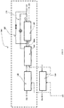
FIGS. 2 ,3 and4 , described in conjunction withFIG. 1 , detailed line illustrations of thesteam generator arrangement 140 are depicted in accordance with various embodiment of the present disclosure. As shown inFIGS. 2 and3 , the steam generator arrangement 140 (boundary by dotted lines) includes aneconomizer section 142, anevaporator section 144 and asuperheater section 148 communicably configured to utilize the heat of the hot thermal storage fluid, at an entrance of theevaporator section 144, received from thefirst storage tank 122 to generate said high pressure steam from the water received from thefeedwater supply 116. InFIGS. 2 and3 , the water-steam supply line is depicted as solid lines, while the hot thermal storage fluid supply line is depicted as dotted lines, in opposite arrow direction to the solid lines, for the sake of easy recognition. The hot thermal storage fluid results in cold thermal storage fluid upon its heat being utilized by thesteam generator arrangement 140, and the resultant cold thermal storage fluid is being directly supplied to thesecond storage tank 124, from thesteam generator arrangement 140 to be stored therein. The said high pressure steam is supplied to thesuperheater section 148 and eventually to thehigh pressure turbine 132 of themultistage steam turbine 130 to drive thereto. After supplying its energy, the steam may be released from a turbine stage downstream of thehigh pressure turbine 132. - The
steam generator arrangement 140 may also include areheat assembly 160. The hot thermal storage fluid from thefirst storage tank 122 may also be supplied to thesteam generator arrangement 140, through thereheat assembly 160, to generate pressure steam, for example intermediate pressure steam, to supply to theintermediate pressure turbine 134. Thereheat assembly 160 may also be utilized to reheat the pressure steam received from the turbine stage downstream of thehigh pressure turbine 132 by the hot thermal storage fluid. The steam from theintermediate pressure turbine 134 is supplied to thelow pressure turbine 136 for driving themultistage steam turbine 130. - In whole of the above description about generation of the steam for smoothly and economically working of the
system 100, without freezing of the thermal storage fluid and without increase of the salt outlet temperature, the steam pressure is limited by the heat balance of thesystem 100. This is because after the water is heated up to saturation temperature in theeconomizer section 142 of thesteam generator arrangement 140, evaporation gets started, thereby naturally setting the evaporation pressure. The steam pressure has a direct impact on the efficiency of the steam cycle. - To improve the efficiency, the
system 100 is configured in such a manner where the steam pressure in thesteam generator arrangement 140 may be freely increased while maintaining the temperature of water entering theeconomizer section 142 above the salt freezing temperature, and the temperature of salt leaving the MSSG at the lowest possible level for safe operation above freezing. To that effect, thesystem 100 includes arecirculation line 170. Therecirculation line 170 is configured around theeconomizer section 142 to recirculate the heated water to aninlet 142a of theeconomizer section 142. The recirculation of the heated water in therecirculation line 170 may be done by a pump of suitable capacity. In this way, the feedwater temperature can be decreased, but the inlet temperature to theeconomizer section 142 can be kept to the desired level to avoid risk of salt freeze, by appropriately setting the amount of recirculated water. The result is a net increase of the heat load on theeconomizer section 142. In one embodiment, as shown inFIG. 2 , therecirculation line 170 is configured from anoutlet 142b of theeconomizer section 142 to theinlet 142a of theeconomizer section 142. In another embodiment, as shown inFIG. 3 , therecirculation line 170 is configured from theevaporator section 144 to theinlet 142a of theeconomizer section 142. In yet further embodiment, as shown inFIG. 4 , theevaporator section 144 may also include asteam drum 146 and in that embodiment therecirculation line 170 may be configured from thesteam drum 146 to theinlet 142a of theeconomizer section 142. - These said arrangements of the
recirculation lines 170 ofFIGS. 2 ,3 and4 allow increasing the pressure range of the variable pressure steam in thesteam generator arrangement 140, in turn increasing the efficiency of the steam cycle while maintaining the temperature of the thermal energy storage fluid at aninlet 144a of theevaporator section 144 and at theoutlet 142b of theeconomizer section 142, and the feedwater temperature to theeconomizer section 142 at desired values.FIGS. 5A and 5B , respectively, depict graphical representations of T-Q diagram illustrating improvement of the present invention (FIG. 5A ) with respect to the conventional one (FIG. 5B ). Increasing the recirculated heated water while decreasing the feedwater temperature to theeconomizer section 142 reduces the slope of the water heating line, this pinches the thermal storage fluid (molten salt) line in a point corresponding to a higher evaporation pressure. - An additional effect of
such recirculation line 170 around theeconomizer section 142 is that the water entering theeconomizer section 142 is be kept at desired level, i.e. 240°C, at full load operation of thesystem 100, by mixing the water with an appropriate amount of the recirculated hot water. - In one further embodiment of the present disclosure, in addition to the
recirculation line 170, thesystem 100 further includes abypass line 180 configured to bypass theeconomizer section 142 to supply the water from thefeedwater supply 116 directly to theevaporator section 144, as shown inFIGS. 2 ,3 and4 . The working conditions for the recirculation andbypass lines FIGS. 1 and5A-B in addition toFIGS. 2 ,3 and4 . Depending upon the operating load conditions (full and part loads), the recirculation andbypass lines - For example, the
bypass line 180 may be important during the part load condition. Generally, at full load condition, the temperature of the thermal storage fluid (molten salt) exiting from theeconomizer section 142 corresponds to the temperature of the second storage tank 124 (cold tank) of about 290°C. Therefore, at part load condition, the temperature of the thermal storage fluid (molten salt) may generally tend to decrease below 290°C. Therecirculation line 170 may be adjusted to increase the water inlet temperature to theeconomizer section 142 to above 240°C, thus controlling the outlet temperature of the thermal storage fluid (molten salt) at 290°C. However, the required recirculation flow may increase and may soon be limited by the maximum capability of therecirculation line 170, typically limited by the capacity of the pump in therecirculation line 170. When this point is reached, the outlet temperature of the thermal storage fluid (molten salt) may be required to slide below 290°C. At lower part load condition, if the temperature of the thermal storage fluid (molten salt) reaches a level, below which there is a risk of freezing, provision may to be taken to overcome thereto. By installing thebypass line 180, part of the water from thefeedwater supply 116 may be directly sent to theevaporator section 144, instead of being sent to theeconomizer section 142, reducing the heat load on theeconomizer section 142 and avoiding the thermal storage fluid (molten salt) to become too cold while being sent to thesecond storage tank 124 to be stored. This enables higher efficiency of thesystem 100 at the part load condition. - In addition to above, the recirculation and
bypass lines steam generator arrangement 140. 'Sliding pressure' means that when the water flow decreases, the steam pressure is decreased proportionally. Lowering the pressure also has the effect of lowering the thermal storage fluid (molten salt) outlet temperature, as it lowers the evaporation temperature in theevaporator section 144 and hence leads to a lower water inlet temperature already at theinlet 142a of theeconomizer section 142. Thebypass line 180 may be used to maintain the thermal storage fluid (molten salt) outlet temperature high and allows operation in the 'sliding pressure' to much lower loads than withoutbypass line 180, while avoiding a drop of the thermal storage fluid (molten salt) outlet temperature from its design value (generally, about 290°C). When operating thesteam generator arrangement 140 in sliding pressure for the part load condition, themultistage steam turbine 130 may be operated with a valve wide open (turbine is a volumetric machine following sliding pressure characteristics). This significantly increases efficiency of the turbine cycle, compared to an operation where the turbine needs to maintain a higher pressure in the steam generator arrangement and therefore needs to throttle the pressure with the turbine inlet valve. - The
system 100 of the present disclosure is advantageous in various scopes such as described above. Apart from above advantageous features described in the disclosure in various embodiment regarding capability of the present invention to increase steam pressure in a steam generator arrangement while preventing freezing of the molten salt improving the efficiency of solar thermal power system, the present invention is also capable of being applicable to steam generator technologies and embodiments including where the economizer, evaporator and superheater sections are separated in dedicated components, assembled in series or parallel, or all the three sections combined in one single component. -
- 100
- Solar thermal power system; System
- 110
- Solar receiver
- 112
- Tower
- 114
- Heliostats
- 116
- Feedwater supply
- 120
- Thermal energy storage arrangement; Thermal storage arrangement
- 122, 124
- First and second storages tanks
- 130
- Multistage steam turbine
- 132
- High pressure steam turbine
- 134
- Intermediate pressure turbine
- 136
- Low pressure turbine
- 140
- Steam generator arrangement
- 142
- Economizer section
- 142a
- Inlet of the economizer
- 142b
- outlet of the economizer
- 144
- Evaporator section
- 144a
- Inlet of evaporator section
- 146
- Steam drum
- 148
- Superheater section
- 150
- Electrical generator
- 160
- Reheat assembly
- 170
- Recirculation line
- 180
- Bypass line
Claims (7)
- A method of operating a solar thermal power system (100) comprising a solar receiver (110), a multistage steam turbine (130), and a steam generator arrangement (140), wherein the steam generator arrangement (140) comprises an economizer section (142), an evaporator section (144) and a superheater section (148), the method including the steps of:circulating a thermal energy storage fluid, included in a thermal energy storage arrangement (120), through the solar receiver (110) to store thermal energy;operating the multistage steam turbine (130) by variable pressure steam, the variable pressure steam being generated from water supplied from a feedwater supply (116) via the thermal energy storage fluid;utilizing the heat of the hot thermal energy storage fluid at an entrance of the evaporator section (144) to generate and supply the variable pressure steam to the superheater section (148) and further to the multistage steam turbine (130);the method characterised in the steps of:recirculating, around the economizer section (142), the heated water to an inlet (142a) of an economizer section (142);increasing heat load on the economizer section (142) in turn increasing pressure range of the variable pressure steam in the steam generator arrangement (140), while maintaining the temperature of the thermal energy storage fluid at an inlet (144a) of the evaporator section (144) and at an outlet (142b) of the economizer section (142), the feedwater temperature to the economizer section (142) at desired values, by adjusting recirculation flow through the recirculating line (170) to control water inlet temperature to the economiser section (142); andmaintaining the temperature of the thermal energy storage fluid leaving the economizer section (142) above a freezing temperature of the thermal energy storage fluid.
- The method of claim 1, wherein the recirculation line (170) is configured from the outlet (142b) of the economizer section (142) to the inlet (142a) of the economizer section (142).
- The method of claim 1, wherein the recirculation line (170) is configured from the evaporator section (144) to the inlet (142a) of the economizer section (142).
- The method of claim 1, wherein the evaporator section (144) comprises a steam drum (146), and in that the recirculation line (170) is configured from the steam drum (146) to the inlet (142a) of the economizer section (142).
- The method of claim 1 further comprising bypassing the economizer section (142) so as to supply the water from the feedwater supply (116) directly to the evaporator section (144).
- The method of claim 1 further comprising reheating steam using a reheat assembly (160) configured to the steam generator arrangement (140).
- The method of claim 1, wherein the thermal energy storage arrangement (120) comprises:storing the hot thermal energy storage fluid in a first storage tank (122) of the thermal energy storage arrangement (120); andstoring the cold thermal energy storage fluid in a second storage tank (124), andsupplying from the thermal energy storage arrangement (120), the cold thermal energy storage fluid from the second storage tank (124) to the solar receiver (110) to be reheated.
Priority Applications (10)
| Application Number | Priority Date | Filing Date | Title |
|---|---|---|---|
| ES14156348T ES2878624T3 (en) | 2014-02-24 | 2014-02-24 | Solar thermal energy system |
| EP14156348.6A EP2910781B1 (en) | 2014-02-24 | 2014-02-24 | Solar thermal power system |
| PT141563486T PT2910781T (en) | 2014-02-24 | 2014-02-24 | Solar thermal power system |
| MA37852A MA37852B1 (en) | 2014-02-24 | 2015-02-12 | Solar thermal energy system |
| ZA2015/00994A ZA201500994B (en) | 2014-02-24 | 2015-02-12 | Solar thermal power system |
| IL237313A IL237313B (en) | 2014-02-24 | 2015-02-19 | Solar thermal power system |
| US14/625,818 US20150240792A1 (en) | 2014-02-24 | 2015-02-19 | Solar thermal power system |
| SA115360326A SA115360326B1 (en) | 2014-02-24 | 2015-02-22 | Solar thermal power system |
| US15/628,130 US9995285B2 (en) | 2014-02-24 | 2017-06-20 | Method for operating a solar thermal power system with an economizer recirculation line |
| CY20211100620T CY1124705T1 (en) | 2014-02-24 | 2021-07-09 | SOLAR THERMAL POWER GENERATION SYSTEM |
Applications Claiming Priority (1)
| Application Number | Priority Date | Filing Date | Title |
|---|---|---|---|
| EP14156348.6A EP2910781B1 (en) | 2014-02-24 | 2014-02-24 | Solar thermal power system |
Publications (2)
| Publication Number | Publication Date |
|---|---|
| EP2910781A1 EP2910781A1 (en) | 2015-08-26 |
| EP2910781B1 true EP2910781B1 (en) | 2021-05-05 |
Family
ID=50151192
Family Applications (1)
| Application Number | Title | Priority Date | Filing Date |
|---|---|---|---|
| EP14156348.6A Active EP2910781B1 (en) | 2014-02-24 | 2014-02-24 | Solar thermal power system |
Country Status (9)
| Country | Link |
|---|---|
| US (2) | US20150240792A1 (en) |
| EP (1) | EP2910781B1 (en) |
| CY (1) | CY1124705T1 (en) |
| ES (1) | ES2878624T3 (en) |
| IL (1) | IL237313B (en) |
| MA (1) | MA37852B1 (en) |
| PT (1) | PT2910781T (en) |
| SA (1) | SA115360326B1 (en) |
| ZA (1) | ZA201500994B (en) |
Families Citing this family (8)
| Publication number | Priority date | Publication date | Assignee | Title |
|---|---|---|---|---|
| PT3086032T (en) * | 2015-04-21 | 2021-01-29 | General Electric Technology Gmbh | Molten salt once-through steam generator |
| WO2017077766A1 (en) * | 2015-11-04 | 2017-05-11 | 三菱日立パワーシステムズ株式会社 | Solar heat collection system and operation method thereof |
| KR102514159B1 (en) * | 2017-12-22 | 2023-03-24 | 존 코케릴 에스.에이. | Heat exchanger for a molten salt steam generator in a concentrated solar power plant (iii) |
| PE20201354A1 (en) * | 2017-12-11 | 2020-11-30 | Cockerill Maintenance And Ingenierie S A | HEAT EXCHANGER FOR A MELTED SALT VAPOR GENERATOR IN A CONCENTRATED SOLAR POWER PLANT (III) |
| US10739083B1 (en) | 2018-08-22 | 2020-08-11 | Walter B. Freeman | System and method for storing thermal energy in a heated liquid in a pressurized vessel |
| EP3663468B1 (en) | 2018-12-07 | 2022-06-01 | SSAB Technology AB | A bucket for an earth-working or materials-handling machine |
| CN109958593B (en) * | 2019-03-11 | 2020-06-02 | 西安交通大学 | Solar energy coal-fired coupling flexible power generation system and operation method |
| CN113587064B (en) * | 2021-07-12 | 2022-05-06 | 西安交通大学 | Mirror field starting and stopping system of photo-thermal power station and control method |
Family Cites Families (20)
| Publication number | Priority date | Publication date | Assignee | Title |
|---|---|---|---|---|
| US3756023A (en) * | 1971-12-01 | 1973-09-04 | Westinghouse Electric Corp | Heat recovery steam generator employing means for preventing economizer steaming |
| CH655548B (en) * | 1982-03-31 | 1986-04-30 | ||
| US4841722A (en) * | 1983-08-26 | 1989-06-27 | General Electric Company | Dual fuel, pressure combined cycle |
| DE3625062A1 (en) | 1986-07-24 | 1988-02-04 | Steinmueller Gmbh L & C | Steam generator with downstream catalytic gas purification and superposed forced circulation |
| US5419285A (en) * | 1994-04-25 | 1995-05-30 | Henry Vogt Machine Co. | Boiler economizer and control system |
| US5904039A (en) * | 1995-05-15 | 1999-05-18 | Siemens Aktiengesellschaft | Method and configuration for deaerating a condensate |
| DE59600840D1 (en) * | 1995-05-15 | 1998-12-24 | Siemens Ag | METHOD AND ARRANGEMENT FOR DEGASSING A CONDENSATE |
| US6460490B1 (en) * | 2001-12-20 | 2002-10-08 | The United States Of America As Represented By The Secretary Of The Navy | Flow control system for a forced recirculation boiler |
| US20080034757A1 (en) | 2005-05-27 | 2008-02-14 | Skowronski Mark J | Method and system integrating solar heat into a regenerative rankine cycle |
| AU2006327452B2 (en) | 2006-06-16 | 2010-07-15 | Kawasaki Jukogyo Kabushiki Kaisha | Solar thermal electric power generation system, heating medium supply system, and temperature fluctuation suppressing device |
| EP1898056A1 (en) * | 2006-09-05 | 2008-03-12 | Cockerill Maintenance & Ingenierie S.A. | Device for heat extraction from the preheated condensate of the steam cycle of a combined cycle plant |
| WO2011080021A2 (en) * | 2009-12-22 | 2011-07-07 | Siemens Aktiengesellschaft | Solar thermal power plant and method for operating a solar thermal power plant |
| US9255569B2 (en) * | 2010-05-03 | 2016-02-09 | Brightsource Industries (Israel) Ltd. | Systems, methods, and devices for operating a solar thermal electricity generating system |
| DE102010041754A1 (en) * | 2010-09-30 | 2012-04-05 | Siemens Aktiengesellschaft | Apparatus and method for generating superheated steam by means of solar energy based on the forced flow concept with helical water / steam guide and use of the superheated steam |
| DE102010041903B4 (en) * | 2010-10-04 | 2017-03-09 | Siemens Aktiengesellschaft | Continuous steam generator with integrated reheater |
| DE102011004280A1 (en) * | 2011-02-17 | 2012-08-23 | Siemens Aktiengesellschaft | Method for operating a solar thermal waste heat steam generator |
| DE102011007370A1 (en) | 2011-04-14 | 2012-10-18 | Siemens Aktiengesellschaft | Solar thermal power plant with storage for a heat transfer medium and method for operating the solar thermal power plant in the unloading mode of the storage |
| WO2013087949A1 (en) * | 2011-12-13 | 2013-06-20 | Ingeteam Power Technology, S.A. | Hybrid system for generating electricity using solar energy and biomass |
| EP2834574B1 (en) * | 2012-01-05 | 2020-08-26 | Norwich Technologies, Inc. | Linear Solar Receiver for Concentrating Solar Power Systems |
| US20150167647A1 (en) * | 2013-12-18 | 2015-06-18 | Bechtel Power Corporation | Concentrating solar power plant with hybrid collector field |
-
2014
- 2014-02-24 EP EP14156348.6A patent/EP2910781B1/en active Active
- 2014-02-24 ES ES14156348T patent/ES2878624T3/en active Active
- 2014-02-24 PT PT141563486T patent/PT2910781T/en unknown
-
2015
- 2015-02-12 ZA ZA2015/00994A patent/ZA201500994B/en unknown
- 2015-02-12 MA MA37852A patent/MA37852B1/en unknown
- 2015-02-19 US US14/625,818 patent/US20150240792A1/en not_active Abandoned
- 2015-02-19 IL IL237313A patent/IL237313B/en active IP Right Grant
- 2015-02-22 SA SA115360326A patent/SA115360326B1/en unknown
-
2017
- 2017-06-20 US US15/628,130 patent/US9995285B2/en active Active
-
2021
- 2021-07-09 CY CY20211100620T patent/CY1124705T1/en unknown
Also Published As
| Publication number | Publication date |
|---|---|
| US20170284378A1 (en) | 2017-10-05 |
| MA37852B1 (en) | 2016-11-30 |
| SA115360326B1 (en) | 2017-12-21 |
| US20150240792A1 (en) | 2015-08-27 |
| ES2878624T3 (en) | 2021-11-19 |
| US9995285B2 (en) | 2018-06-12 |
| ZA201500994B (en) | 2016-01-27 |
| PT2910781T (en) | 2021-07-07 |
| IL237313B (en) | 2020-03-31 |
| CY1124705T1 (en) | 2022-07-22 |
| EP2910781A1 (en) | 2015-08-26 |
| MA20150336A1 (en) | 2015-10-30 |
Similar Documents
| Publication | Publication Date | Title |
|---|---|---|
| EP2910781B1 (en) | Solar thermal power system | |
| JP4786504B2 (en) | Heat medium supply facility, solar combined power generation facility, and control method thereof | |
| CN108291532B (en) | Solar power generation device and control method thereof | |
| US20080034757A1 (en) | Method and system integrating solar heat into a regenerative rankine cycle | |
| US10401022B2 (en) | Molten salt once-through steam generator | |
| US9494141B2 (en) | Solar thermal power system | |
| US9194377B2 (en) | Auxiliary steam supply system in solar power plants | |
| EP2765357B1 (en) | Steam power plant with an additional flexible solar system for the flexible integration of solar energy | |
| EP3051129B1 (en) | Solar thermal power system | |
| WO2017025124A1 (en) | Method for adjusting steam generator pressure in solar power plant | |
| JP2016160775A (en) | Hybrid power system with solar heat and fuel boiler and control method therefor | |
| JP6419512B2 (en) | Thermal storage power plant and method for operating the same | |
| CN102213118B (en) | Steam-turbine unit | |
| CA2835604C (en) | Steam power plant with an additional flexible solar system for the flexible integration of solar energy | |
| US20230287808A1 (en) | Start-up and control of liquid salt energy storage combined cycle systems | |
| WO2013013682A1 (en) | Arrangement and method for load change compensation at a saturated steam turbine | |
| ITMS20100004A1 (en) | HYBRID CENTRAL ELIOTHERMONUCLEAR |
Legal Events
| Date | Code | Title | Description |
|---|---|---|---|
| PUAI | Public reference made under article 153(3) epc to a published international application that has entered the european phase |
Free format text: ORIGINAL CODE: 0009012 |
|
| 17P | Request for examination filed |
Effective date: 20140224 |
|
| AK | Designated contracting states |
Kind code of ref document: A1 Designated state(s): AL AT BE BG CH CY CZ DE DK EE ES FI FR GB GR HR HU IE IS IT LI LT LU LV MC MK MT NL NO PL PT RO RS SE SI SK SM TR |
|
| AX | Request for extension of the european patent |
Extension state: BA ME |
|
| RAP1 | Party data changed (applicant data changed or rights of an application transferred) |
Owner name: GENERAL ELECTRIC TECHNOLOGY GMBH |
|
| STAA | Information on the status of an ep patent application or granted ep patent |
Free format text: STATUS: EXAMINATION IS IN PROGRESS |
|
| 17Q | First examination report despatched |
Effective date: 20161221 |
|
| GRAP | Despatch of communication of intention to grant a patent |
Free format text: ORIGINAL CODE: EPIDOSNIGR1 |
|
| STAA | Information on the status of an ep patent application or granted ep patent |
Free format text: STATUS: GRANT OF PATENT IS INTENDED |
|
| RIC1 | Information provided on ipc code assigned before grant |
Ipc: F22D 1/00 20060101ALI20201112BHEP Ipc: F01K 1/14 20060101ALI20201112BHEP Ipc: F22B 1/00 20060101ALI20201112BHEP Ipc: F03G 6/06 20060101AFI20201112BHEP |
|
| INTG | Intention to grant announced |
Effective date: 20201203 |
|
| GRAS | Grant fee paid |
Free format text: ORIGINAL CODE: EPIDOSNIGR3 |
|
| GRAA | (expected) grant |
Free format text: ORIGINAL CODE: 0009210 |
|
| STAA | Information on the status of an ep patent application or granted ep patent |
Free format text: STATUS: THE PATENT HAS BEEN GRANTED |
|
| AK | Designated contracting states |
Kind code of ref document: B1 Designated state(s): AL AT BE BG CH CY CZ DE DK EE ES FI FR GB GR HR HU IE IS IT LI LT LU LV MC MK MT NL NO PL PT RO RS SE SI SK SM TR |
|
| REG | Reference to a national code |
Ref country code: GB Ref legal event code: FG4D |
|
| REG | Reference to a national code |
Ref country code: CH Ref legal event code: EP |
|
| REG | Reference to a national code |
Ref country code: AT Ref legal event code: REF Ref document number: 1390123 Country of ref document: AT Kind code of ref document: T Effective date: 20210515 |
|
| REG | Reference to a national code |
Ref country code: DE Ref legal event code: R096 Ref document number: 602014077118 Country of ref document: DE |
|
| REG | Reference to a national code |
Ref country code: IE Ref legal event code: FG4D |
|
| REG | Reference to a national code |
Ref country code: PT Ref legal event code: SC4A Ref document number: 2910781 Country of ref document: PT Date of ref document: 20210707 Kind code of ref document: T Free format text: AVAILABILITY OF NATIONAL TRANSLATION Effective date: 20210630 |
|
| RAP4 | Party data changed (patent owner data changed or rights of a patent transferred) |
Owner name: GENERAL ELECTRIC TECHNOLOGY GMBH |
|
| REG | Reference to a national code |
Ref country code: LT Ref legal event code: MG9D |
|
| REG | Reference to a national code |
Ref country code: GR Ref legal event code: EP Ref document number: 20210401792 Country of ref document: GR Effective date: 20210813 |
|
| REG | Reference to a national code |
Ref country code: AT Ref legal event code: MK05 Ref document number: 1390123 Country of ref document: AT Kind code of ref document: T Effective date: 20210505 |
|
| PG25 | Lapsed in a contracting state [announced via postgrant information from national office to epo] |
Ref country code: HR Free format text: LAPSE BECAUSE OF FAILURE TO SUBMIT A TRANSLATION OF THE DESCRIPTION OR TO PAY THE FEE WITHIN THE PRESCRIBED TIME-LIMIT Effective date: 20210505 Ref country code: FI Free format text: LAPSE BECAUSE OF FAILURE TO SUBMIT A TRANSLATION OF THE DESCRIPTION OR TO PAY THE FEE WITHIN THE PRESCRIBED TIME-LIMIT Effective date: 20210505 Ref country code: LT Free format text: LAPSE BECAUSE OF FAILURE TO SUBMIT A TRANSLATION OF THE DESCRIPTION OR TO PAY THE FEE WITHIN THE PRESCRIBED TIME-LIMIT Effective date: 20210505 Ref country code: BG Free format text: LAPSE BECAUSE OF FAILURE TO SUBMIT A TRANSLATION OF THE DESCRIPTION OR TO PAY THE FEE WITHIN THE PRESCRIBED TIME-LIMIT Effective date: 20210805 Ref country code: AT Free format text: LAPSE BECAUSE OF FAILURE TO SUBMIT A TRANSLATION OF THE DESCRIPTION OR TO PAY THE FEE WITHIN THE PRESCRIBED TIME-LIMIT Effective date: 20210505 |
|
| REG | Reference to a national code |
Ref country code: ES Ref legal event code: FG2A Ref document number: 2878624 Country of ref document: ES Kind code of ref document: T3 Effective date: 20211119 |
|
| PG25 | Lapsed in a contracting state [announced via postgrant information from national office to epo] |
Ref country code: LV Free format text: LAPSE BECAUSE OF FAILURE TO SUBMIT A TRANSLATION OF THE DESCRIPTION OR TO PAY THE FEE WITHIN THE PRESCRIBED TIME-LIMIT Effective date: 20210505 Ref country code: IS Free format text: LAPSE BECAUSE OF FAILURE TO SUBMIT A TRANSLATION OF THE DESCRIPTION OR TO PAY THE FEE WITHIN THE PRESCRIBED TIME-LIMIT Effective date: 20210905 Ref country code: RS Free format text: LAPSE BECAUSE OF FAILURE TO SUBMIT A TRANSLATION OF THE DESCRIPTION OR TO PAY THE FEE WITHIN THE PRESCRIBED TIME-LIMIT Effective date: 20210505 Ref country code: SE Free format text: LAPSE BECAUSE OF FAILURE TO SUBMIT A TRANSLATION OF THE DESCRIPTION OR TO PAY THE FEE WITHIN THE PRESCRIBED TIME-LIMIT Effective date: 20210505 Ref country code: PL Free format text: LAPSE BECAUSE OF FAILURE TO SUBMIT A TRANSLATION OF THE DESCRIPTION OR TO PAY THE FEE WITHIN THE PRESCRIBED TIME-LIMIT Effective date: 20210505 Ref country code: NO Free format text: LAPSE BECAUSE OF FAILURE TO SUBMIT A TRANSLATION OF THE DESCRIPTION OR TO PAY THE FEE WITHIN THE PRESCRIBED TIME-LIMIT Effective date: 20210805 |
|
| REG | Reference to a national code |
Ref country code: NL Ref legal event code: MP Effective date: 20210505 |
|
| PG25 | Lapsed in a contracting state [announced via postgrant information from national office to epo] |
Ref country code: NL Free format text: LAPSE BECAUSE OF FAILURE TO SUBMIT A TRANSLATION OF THE DESCRIPTION OR TO PAY THE FEE WITHIN THE PRESCRIBED TIME-LIMIT Effective date: 20210505 |
|
| PG25 | Lapsed in a contracting state [announced via postgrant information from national office to epo] |
Ref country code: RO Free format text: LAPSE BECAUSE OF FAILURE TO SUBMIT A TRANSLATION OF THE DESCRIPTION OR TO PAY THE FEE WITHIN THE PRESCRIBED TIME-LIMIT Effective date: 20210505 Ref country code: EE Free format text: LAPSE BECAUSE OF FAILURE TO SUBMIT A TRANSLATION OF THE DESCRIPTION OR TO PAY THE FEE WITHIN THE PRESCRIBED TIME-LIMIT Effective date: 20210505 Ref country code: CZ Free format text: LAPSE BECAUSE OF FAILURE TO SUBMIT A TRANSLATION OF THE DESCRIPTION OR TO PAY THE FEE WITHIN THE PRESCRIBED TIME-LIMIT Effective date: 20210505 Ref country code: DK Free format text: LAPSE BECAUSE OF FAILURE TO SUBMIT A TRANSLATION OF THE DESCRIPTION OR TO PAY THE FEE WITHIN THE PRESCRIBED TIME-LIMIT Effective date: 20210505 Ref country code: SK Free format text: LAPSE BECAUSE OF FAILURE TO SUBMIT A TRANSLATION OF THE DESCRIPTION OR TO PAY THE FEE WITHIN THE PRESCRIBED TIME-LIMIT Effective date: 20210505 Ref country code: SM Free format text: LAPSE BECAUSE OF FAILURE TO SUBMIT A TRANSLATION OF THE DESCRIPTION OR TO PAY THE FEE WITHIN THE PRESCRIBED TIME-LIMIT Effective date: 20210505 |
|
| REG | Reference to a national code |
Ref country code: DE Ref legal event code: R097 Ref document number: 602014077118 Country of ref document: DE |
|
| PLBE | No opposition filed within time limit |
Free format text: ORIGINAL CODE: 0009261 |
|
| STAA | Information on the status of an ep patent application or granted ep patent |
Free format text: STATUS: NO OPPOSITION FILED WITHIN TIME LIMIT |
|
| 26N | No opposition filed |
Effective date: 20220208 |
|
| PG25 | Lapsed in a contracting state [announced via postgrant information from national office to epo] |
Ref country code: IS Free format text: LAPSE BECAUSE OF FAILURE TO SUBMIT A TRANSLATION OF THE DESCRIPTION OR TO PAY THE FEE WITHIN THE PRESCRIBED TIME-LIMIT Effective date: 20210905 Ref country code: AL Free format text: LAPSE BECAUSE OF FAILURE TO SUBMIT A TRANSLATION OF THE DESCRIPTION OR TO PAY THE FEE WITHIN THE PRESCRIBED TIME-LIMIT Effective date: 20210505 |
|
| REG | Reference to a national code |
Ref country code: DE Ref legal event code: R119 Ref document number: 602014077118 Country of ref document: DE |
|
| PG25 | Lapsed in a contracting state [announced via postgrant information from national office to epo] |
Ref country code: MC Free format text: LAPSE BECAUSE OF FAILURE TO SUBMIT A TRANSLATION OF THE DESCRIPTION OR TO PAY THE FEE WITHIN THE PRESCRIBED TIME-LIMIT Effective date: 20210505 |
|
| REG | Reference to a national code |
Ref country code: CH Ref legal event code: PL |
|
| REG | Reference to a national code |
Ref country code: BE Ref legal event code: MM Effective date: 20220228 |
|
| GBPC | Gb: european patent ceased through non-payment of renewal fee |
Effective date: 20220224 |
|
| PG25 | Lapsed in a contracting state [announced via postgrant information from national office to epo] |
Ref country code: LU Free format text: LAPSE BECAUSE OF NON-PAYMENT OF DUE FEES Effective date: 20220224 |
|
| PG25 | Lapsed in a contracting state [announced via postgrant information from national office to epo] |
Ref country code: FR Free format text: LAPSE BECAUSE OF NON-PAYMENT OF DUE FEES Effective date: 20220228 |
|
| PG25 | Lapsed in a contracting state [announced via postgrant information from national office to epo] |
Ref country code: LI Free format text: LAPSE BECAUSE OF NON-PAYMENT OF DUE FEES Effective date: 20220228 Ref country code: IE Free format text: LAPSE BECAUSE OF NON-PAYMENT OF DUE FEES Effective date: 20220224 Ref country code: GB Free format text: LAPSE BECAUSE OF NON-PAYMENT OF DUE FEES Effective date: 20220224 Ref country code: DE Free format text: LAPSE BECAUSE OF NON-PAYMENT OF DUE FEES Effective date: 20220901 Ref country code: CH Free format text: LAPSE BECAUSE OF NON-PAYMENT OF DUE FEES Effective date: 20220228 |
|
| PG25 | Lapsed in a contracting state [announced via postgrant information from national office to epo] |
Ref country code: BE Free format text: LAPSE BECAUSE OF NON-PAYMENT OF DUE FEES Effective date: 20220228 |
|
| PGFP | Annual fee paid to national office [announced via postgrant information from national office to epo] |
Ref country code: ES Payment date: 20230301 Year of fee payment: 10 |
|
| PGFP | Annual fee paid to national office [announced via postgrant information from national office to epo] |
Ref country code: TR Payment date: 20230124 Year of fee payment: 10 Ref country code: PT Payment date: 20230123 Year of fee payment: 10 Ref country code: IT Payment date: 20230120 Year of fee payment: 10 Ref country code: GR Payment date: 20230120 Year of fee payment: 10 Ref country code: CY Payment date: 20230120 Year of fee payment: 10 |
|
| P01 | Opt-out of the competence of the unified patent court (upc) registered |
Effective date: 20230523 |
|
| PG25 | Lapsed in a contracting state [announced via postgrant information from national office to epo] |
Ref country code: HU Free format text: LAPSE BECAUSE OF FAILURE TO SUBMIT A TRANSLATION OF THE DESCRIPTION OR TO PAY THE FEE WITHIN THE PRESCRIBED TIME-LIMIT; INVALID AB INITIO Effective date: 20140224 |
|
| PGFP | Annual fee paid to national office [announced via postgrant information from national office to epo] |
Ref country code: GR Payment date: 20240125 Year of fee payment: 11 |
|
| PGFP | Annual fee paid to national office [announced via postgrant information from national office to epo] |
Ref country code: ES Payment date: 20240301 Year of fee payment: 11 |