EP2910693B1 - Mit bodenquellenwärmepumpe und regeneriertem wasser kompatibles wasserversorgungsrohrnetzwerksystem - Google Patents
Mit bodenquellenwärmepumpe und regeneriertem wasser kompatibles wasserversorgungsrohrnetzwerksystem Download PDFInfo
- Publication number
- EP2910693B1 EP2910693B1 EP13839707.0A EP13839707A EP2910693B1 EP 2910693 B1 EP2910693 B1 EP 2910693B1 EP 13839707 A EP13839707 A EP 13839707A EP 2910693 B1 EP2910693 B1 EP 2910693B1
- Authority
- EP
- European Patent Office
- Prior art keywords
- water
- pipe
- distribution
- water supply
- return
- Prior art date
- Legal status (The legal status is an assumption and is not a legal conclusion. Google has not performed a legal analysis and makes no representation as to the accuracy of the status listed.)
- Not-in-force
Links
- XLYOFNOQVPJJNP-UHFFFAOYSA-N water Substances O XLYOFNOQVPJJNP-UHFFFAOYSA-N 0.000 title claims description 1345
- 238000009826 distribution Methods 0.000 claims description 398
- 230000005540 biological transmission Effects 0.000 claims description 60
- 230000005484 gravity Effects 0.000 claims description 25
- 239000010865 sewage Substances 0.000 claims description 22
- 239000002352 surface water Substances 0.000 claims description 8
- 239000003673 groundwater Substances 0.000 claims description 5
- 238000011268 retreatment Methods 0.000 claims description 5
- 239000002699 waste material Substances 0.000 claims 1
- 238000011161 development Methods 0.000 description 32
- 238000010276 construction Methods 0.000 description 23
- 238000005516 engineering process Methods 0.000 description 19
- 238000001816 cooling Methods 0.000 description 16
- 238000010438 heat treatment Methods 0.000 description 9
- 230000007547 defect Effects 0.000 description 4
- 238000010586 diagram Methods 0.000 description 4
- 230000009977 dual effect Effects 0.000 description 4
- 238000003860 storage Methods 0.000 description 4
- 238000004378 air conditioning Methods 0.000 description 3
- 235000012206 bottled water Nutrition 0.000 description 3
- 239000003651 drinking water Substances 0.000 description 3
- 238000007726 management method Methods 0.000 description 3
- 230000008859 change Effects 0.000 description 2
- 230000000694 effects Effects 0.000 description 2
- 230000007613 environmental effect Effects 0.000 description 2
- 239000000446 fuel Substances 0.000 description 2
- 230000006872 improvement Effects 0.000 description 2
- 238000005304 joining Methods 0.000 description 2
- 238000004519 manufacturing process Methods 0.000 description 2
- 239000000203 mixture Substances 0.000 description 2
- 238000011160 research Methods 0.000 description 2
- 239000011435 rock Substances 0.000 description 2
- 230000002459 sustained effect Effects 0.000 description 2
- 239000002918 waste heat Substances 0.000 description 2
- 229910052799 carbon Inorganic materials 0.000 description 1
- 230000001149 cognitive effect Effects 0.000 description 1
- 239000012141 concentrate Substances 0.000 description 1
- 238000009430 construction management Methods 0.000 description 1
- 230000003247 decreasing effect Effects 0.000 description 1
- 238000013461 design Methods 0.000 description 1
- 238000004134 energy conservation Methods 0.000 description 1
- 238000005265 energy consumption Methods 0.000 description 1
- 239000003344 environmental pollutant Substances 0.000 description 1
- 238000003912 environmental pollution Methods 0.000 description 1
- 230000036541 health Effects 0.000 description 1
- 238000009434 installation Methods 0.000 description 1
- 230000010354 integration Effects 0.000 description 1
- 238000011835 investigation Methods 0.000 description 1
- 238000012423 maintenance Methods 0.000 description 1
- 231100000719 pollutant Toxicity 0.000 description 1
- 238000012545 processing Methods 0.000 description 1
- 238000005086 pumping Methods 0.000 description 1
- 238000004064 recycling Methods 0.000 description 1
- 230000002441 reversible effect Effects 0.000 description 1
- 239000002689 soil Substances 0.000 description 1
- 230000004083 survival effect Effects 0.000 description 1
- 239000008399 tap water Substances 0.000 description 1
- 235000020679 tap water Nutrition 0.000 description 1
- 238000009423 ventilation Methods 0.000 description 1
- 239000002351 wastewater Substances 0.000 description 1
- 238000004065 wastewater treatment Methods 0.000 description 1
- 239000003643 water by type Substances 0.000 description 1
Images


Classifications
-
- F—MECHANICAL ENGINEERING; LIGHTING; HEATING; WEAPONS; BLASTING
- F24—HEATING; RANGES; VENTILATING
- F24D—DOMESTIC- OR SPACE-HEATING SYSTEMS, e.g. CENTRAL HEATING SYSTEMS; DOMESTIC HOT-WATER SUPPLY SYSTEMS; ELEMENTS OR COMPONENTS THEREFOR
- F24D17/00—Domestic hot-water supply systems
- F24D17/0005—Domestic hot-water supply systems using recuperation of waste heat
-
- F—MECHANICAL ENGINEERING; LIGHTING; HEATING; WEAPONS; BLASTING
- F24—HEATING; RANGES; VENTILATING
- F24D—DOMESTIC- OR SPACE-HEATING SYSTEMS, e.g. CENTRAL HEATING SYSTEMS; DOMESTIC HOT-WATER SUPPLY SYSTEMS; ELEMENTS OR COMPONENTS THEREFOR
- F24D17/00—Domestic hot-water supply systems
- F24D17/02—Domestic hot-water supply systems using heat pumps
-
- F—MECHANICAL ENGINEERING; LIGHTING; HEATING; WEAPONS; BLASTING
- F24—HEATING; RANGES; VENTILATING
- F24T—GEOTHERMAL COLLECTORS; GEOTHERMAL SYSTEMS
- F24T10/00—Geothermal collectors
- F24T10/10—Geothermal collectors with circulation of working fluids through underground channels, the working fluids not coming into direct contact with the ground
-
- F—MECHANICAL ENGINEERING; LIGHTING; HEATING; WEAPONS; BLASTING
- F24—HEATING; RANGES; VENTILATING
- F24D—DOMESTIC- OR SPACE-HEATING SYSTEMS, e.g. CENTRAL HEATING SYSTEMS; DOMESTIC HOT-WATER SUPPLY SYSTEMS; ELEMENTS OR COMPONENTS THEREFOR
- F24D2200/00—Heat sources or energy sources
- F24D2200/11—Geothermal energy
-
- F—MECHANICAL ENGINEERING; LIGHTING; HEATING; WEAPONS; BLASTING
- F24—HEATING; RANGES; VENTILATING
- F24D—DOMESTIC- OR SPACE-HEATING SYSTEMS, e.g. CENTRAL HEATING SYSTEMS; DOMESTIC HOT-WATER SUPPLY SYSTEMS; ELEMENTS OR COMPONENTS THEREFOR
- F24D2200/00—Heat sources or energy sources
- F24D2200/12—Heat pump
-
- F—MECHANICAL ENGINEERING; LIGHTING; HEATING; WEAPONS; BLASTING
- F24—HEATING; RANGES; VENTILATING
- F24D—DOMESTIC- OR SPACE-HEATING SYSTEMS, e.g. CENTRAL HEATING SYSTEMS; DOMESTIC HOT-WATER SUPPLY SYSTEMS; ELEMENTS OR COMPONENTS THEREFOR
- F24D2200/00—Heat sources or energy sources
- F24D2200/16—Waste heat
- F24D2200/20—Sewage water
-
- F—MECHANICAL ENGINEERING; LIGHTING; HEATING; WEAPONS; BLASTING
- F25—REFRIGERATION OR COOLING; COMBINED HEATING AND REFRIGERATION SYSTEMS; HEAT PUMP SYSTEMS; MANUFACTURE OR STORAGE OF ICE; LIQUEFACTION SOLIDIFICATION OF GASES
- F25B—REFRIGERATION MACHINES, PLANTS OR SYSTEMS; COMBINED HEATING AND REFRIGERATION SYSTEMS; HEAT PUMP SYSTEMS
- F25B30/00—Heat pumps
- F25B30/06—Heat pumps characterised by the source of low potential heat
-
- Y—GENERAL TAGGING OF NEW TECHNOLOGICAL DEVELOPMENTS; GENERAL TAGGING OF CROSS-SECTIONAL TECHNOLOGIES SPANNING OVER SEVERAL SECTIONS OF THE IPC; TECHNICAL SUBJECTS COVERED BY FORMER USPC CROSS-REFERENCE ART COLLECTIONS [XRACs] AND DIGESTS
- Y02—TECHNOLOGIES OR APPLICATIONS FOR MITIGATION OR ADAPTATION AGAINST CLIMATE CHANGE
- Y02B—CLIMATE CHANGE MITIGATION TECHNOLOGIES RELATED TO BUILDINGS, e.g. HOUSING, HOUSE APPLIANCES OR RELATED END-USER APPLICATIONS
- Y02B10/00—Integration of renewable energy sources in buildings
- Y02B10/40—Geothermal heat-pumps
-
- Y—GENERAL TAGGING OF NEW TECHNOLOGICAL DEVELOPMENTS; GENERAL TAGGING OF CROSS-SECTIONAL TECHNOLOGIES SPANNING OVER SEVERAL SECTIONS OF THE IPC; TECHNICAL SUBJECTS COVERED BY FORMER USPC CROSS-REFERENCE ART COLLECTIONS [XRACs] AND DIGESTS
- Y02—TECHNOLOGIES OR APPLICATIONS FOR MITIGATION OR ADAPTATION AGAINST CLIMATE CHANGE
- Y02B—CLIMATE CHANGE MITIGATION TECHNOLOGIES RELATED TO BUILDINGS, e.g. HOUSING, HOUSE APPLIANCES OR RELATED END-USER APPLICATIONS
- Y02B10/00—Integration of renewable energy sources in buildings
- Y02B10/70—Hybrid systems, e.g. uninterruptible or back-up power supplies integrating renewable energies
-
- Y—GENERAL TAGGING OF NEW TECHNOLOGICAL DEVELOPMENTS; GENERAL TAGGING OF CROSS-SECTIONAL TECHNOLOGIES SPANNING OVER SEVERAL SECTIONS OF THE IPC; TECHNICAL SUBJECTS COVERED BY FORMER USPC CROSS-REFERENCE ART COLLECTIONS [XRACs] AND DIGESTS
- Y02—TECHNOLOGIES OR APPLICATIONS FOR MITIGATION OR ADAPTATION AGAINST CLIMATE CHANGE
- Y02B—CLIMATE CHANGE MITIGATION TECHNOLOGIES RELATED TO BUILDINGS, e.g. HOUSING, HOUSE APPLIANCES OR RELATED END-USER APPLICATIONS
- Y02B30/00—Energy efficient heating, ventilation or air conditioning [HVAC]
- Y02B30/18—Domestic hot-water supply systems using recuperated or waste heat
-
- Y—GENERAL TAGGING OF NEW TECHNOLOGICAL DEVELOPMENTS; GENERAL TAGGING OF CROSS-SECTIONAL TECHNOLOGIES SPANNING OVER SEVERAL SECTIONS OF THE IPC; TECHNICAL SUBJECTS COVERED BY FORMER USPC CROSS-REFERENCE ART COLLECTIONS [XRACs] AND DIGESTS
- Y02—TECHNOLOGIES OR APPLICATIONS FOR MITIGATION OR ADAPTATION AGAINST CLIMATE CHANGE
- Y02B—CLIMATE CHANGE MITIGATION TECHNOLOGIES RELATED TO BUILDINGS, e.g. HOUSING, HOUSE APPLIANCES OR RELATED END-USER APPLICATIONS
- Y02B30/00—Energy efficient heating, ventilation or air conditioning [HVAC]
- Y02B30/52—Heat recovery pumps, i.e. heat pump based systems or units able to transfer the thermal energy from one area of the premises or part of the facilities to a different one, improving the overall efficiency
-
- Y—GENERAL TAGGING OF NEW TECHNOLOGICAL DEVELOPMENTS; GENERAL TAGGING OF CROSS-SECTIONAL TECHNOLOGIES SPANNING OVER SEVERAL SECTIONS OF THE IPC; TECHNICAL SUBJECTS COVERED BY FORMER USPC CROSS-REFERENCE ART COLLECTIONS [XRACs] AND DIGESTS
- Y02—TECHNOLOGIES OR APPLICATIONS FOR MITIGATION OR ADAPTATION AGAINST CLIMATE CHANGE
- Y02E—REDUCTION OF GREENHOUSE GAS [GHG] EMISSIONS, RELATED TO ENERGY GENERATION, TRANSMISSION OR DISTRIBUTION
- Y02E10/00—Energy generation through renewable energy sources
- Y02E10/10—Geothermal energy
Definitions
- the present disclosure relates to district public water supply pipe network system and more particularly, to district public water supply pipe network system compatible for source side water for ground source heat pump system and reclaimed water, which not only provides the ground source heat pumping system in the district with source side water as cooling/heating source , but provides the user in the district with reclaimed water, combining two networks together so that providing one network with dual functions.
- Ground source heat pump technology is an energy saving, environmentally friendly HVAC (Heat Ventilation and Air-Conditioning) technology, which utilizes energy stored in shallow geothermal energy resources in the earth surface such as rock soil mass, underground water, surface water ,e.g. river, lake, sea etc., municipal sewage and waste water for cooling or heating.
- HVAC Heating Ventilation and Air-Conditioning
- the ground-source heat pump system may be classified as follows:
- ground-source heat pump is constructed as individual project, i.e. in accordance with the available resource, environment and execution conditions of individual buildings, specific type of ground source heat pump system is constructed, and operate individually.
- specific type of ground source heat pump system is constructed, and operate individually.
- Reclaimed water is non-potable water which is obtained by deeply treating sewage and meets predetermined criterion and may be used within limits. According to statistics, 80% volume of urban water consumption is converted into sewage, 70% volume of which could be converted into reclaimed water after deeply treatment. This means that over 50% volume of urban water consumption may be converted into reclaimed water. Therefore, the reclaimed water resource is a water source with large volume, low cost and distribution convenience for urban area. In addition, it facilitates the development of urban sewage treatment and reduces the pollution of urban sewage. Sewage treatment and utilization of reclaimed water is economic and environmentally friendly.
- WO 03/012348 A2 discloses an excavationless geothermal system for heating and cooling applications.
- the system includes a portable water storage container that receives water from a commercial water supply through a supply line and a reversible water meter.
- the storage container is coupled to a heat pump so that the temperature of the water in the storage container is increased or decreased by the heat pump.
- the water in the storage container may be supplied to a fuel cell so that waste heat from the fuel cell is delivered to the heat pump.
- the water may also be supplied to a household water usage system, and returned to the supply line after being treated to improve water quality.
- the commercial water supply provides drinkable water, both for the household water usage system and for the heat pump.
- the heat pump is used for heating and cooling applications, and consumes plenty of drinkable water, which is expensive and impracticable. Moreover, the water is returned to the supply line after being treated to improve water quality, which will change the temperature of the water in the supply line, and the heat pump will not work normally due to the change of the temperature. Furthermore, the water is returned to the supply line after being treated to improve water quality, which is not allowed by some standards of the commercial water supply due to potential risk of contaminating the drinkable water. This system is not related to acquisition, transport and usage of the reclaimed water in the heating and cooling applications.
- CN 201 582 904 U describes a central heating system which incorporates a water source heat pump.
- the water source heat pump is connected in series with a return pipe on a primary side or a secondary side of each heat-exchange station of the existing central heating system, so that the temperature of return water is increased by the water source heat pump, which improves thermal efficiency, save energy, reduce emissions, and improve system reliability.
- the system is not related to acquisition, transport and usage of the reclaimed water and the source side water.
- the present invention proposed a technical solution by using the special nature of the reclaimed water as both water resources and energy, which fully solved the problems in the use of reclaimed water and in the construction development of ground source heat pump.
- a district public water supply pipe network system compatible for source side water of ground source heat pump and reclaimed water, which can be used both as cold/heat source of any water source heat pump units within certain district and as reclaimed water source of any user within certain region.
- this network is not only the district side water pipe network with water source heat pump system, but also the reclaimed water pipe network, joining two networks together, realizing one network dual purposes.
- a water supply system particularly, a district public water supply pipe network system compatible for source side water for ground source heat pump system and reclaimed water, comprises a main water supply pipe connected with the reclaimed water outlet side of a sewage treatment system; the main water supply pipe is connected with plurality of energy stations and transmission and distribution stations; a water return main pipe is arranged between the adjacent energy stations; the energy station comprises plurality of shallow geothermal energy exchange systems which exchange heat with the district shallow geothermal energy sources; the energy station and the transmission and distribution station are connected with distribution pipe networks respectively; wherein the outlet at the distribution side of the energy station is connected with the water supply pipeline of corresponding distribution pipe network through a distribution water pump and a water supply distribution pipe; the energy station is connected with the water return pipeline of corresponding distribution pipe network by a water return distribution pipe.
- the distribution pipe network is connected with the user side water supply system.
- the energy station as the energy hub of the pipe network, has two major functions: First, it could, according to the characteristics of shallow geothermal resources in different locations within the certain region, select one or more forms of shallow ground heat resources for collection, processing and integration, to make the technical parameters such as temperature, pressure, and flow rate of the transmission medium flowed in the pipe network (side water and reclaimed water) to achieve the operation requirements of the ground source heat pump units. At the same time, it could also make the water quality achieve both the circulating operation requirements of ground source heat pump system and the usage standard of reclaimed water.
- the energy station adopted in the present invention comprises an distribution pool, a collection pool and an reclaimed water treatment system.
- the distribution pool is connected with the main water supply pipe to receive both the source side water and reclaimed water from it.
- the outlet at the distribution side of the distribution pool is connected with the water supply distribution pipe of the corresponding distribution pipe network through a distribution water pump of the energy station.
- the inlet of the collection pool is connected with the water return pipeline of corresponding distribution pipe network.
- the outlet of the collection pool is connected with the inlet of the reclaimed water treatment system through pipeline.
- the reclaimed water treatment system is configured to have one or more outlets.
- the outlet When there is only one outlet, the outlet is connected with the inlet of the shallow geothermal energy exchange system corresponding to the energy station through a circulating water, and the outlet of the shallow geothermal energy exchange system is connected with the first inlet of the distribution pool through an outlet pipe of the shallow geothermal energy exchange system.
- at least one other outlet of reclaimed water treatment systems of both energy system is connected with the inlet of the one other shallow geothermal energy exchange system corresponding to the energy station through the circulating water, and the outlet of the one other shallow geothermal energy exchange system is connected with the second inlet of the distribution pool through the outlet pipe of the energy exchange system.
- the outlet side of the shallow geothermal energy exchange system connected with the second inlet of the distribution pool is connected with the distribution pool through the outlet pipe of the energy exchange system and the reclaimed water treatment system installed thereon.
- the inlet of the main water supply pipe is connected with a water supply pump for main water supply pipe in the reclaimed water outlet of the sewage treatment system
- the outlet of the main water supply pipe is connected with an inlet of the distribution pool in a first energy station,.
- a water supply pump for main water supply pipe which is mounted at the outlet of the distribution pool in the first energy station is connected with the inlet of the next section of main water supply pipe,.
- the outlet of the next section of the main water supply pipe is connected with inlet of the distribution pool in the second energy station, and so on until the last energy station.
- the water return main pipe is arranged between collection pools of two adjacent energy stations.
- a return connector of collection pool of the previous energy station is connected with head port of water return main pipe through return water pump for water return main pipe and control valve for water return main pipe in sequence.
- a tail port of the water return main pipe is connected with a first return connector of collection pool of next energy station through a control valve and a return water pump for water return main pipe.
- a second return connector of the collection pool is connected with the head port of the next section of water return main pipe through a return water pump and a control valve for water return main pipe in sequence, and so on until the last energy station.
- the head port and tail port of each water return main pipe are connected with corresponding collection pool respectively by bypass valves and bypass pipes.
- the flow direction of the source side water in the water return main pipe may be adjusted by opening and shutting down various return water pumps and control valves.
- the source side water participating in the thermal cycle may be adjusted and distributed in the water return main pipe, so that the quality of the source side water in the system can be guaranteed, and the balance between the energy and the water flow rate in the district can be kept.
- the source side water which has exchanged heat in the thermal cycle of the water source heat pump units could be transported back to the collection pool of energy station.
- the source side water transported back is treated by the reclaimed water treatment system, and then transported to the shallow geothermal energy exchange system to exchange heat again.
- the shallow geothermal energy exchange system which exchanges heat with the district shallow geothermal energy sources may be any one as follows: ground-coupled heat exchange system, ground water source heat exchange system, surface water source heat exchange system and water source heat exchange system the district shallow geothermal exchange may also adopt renewable energy source heat exchange system, unused energy source heat exchange system or residual source heat exchange system.
- the outlet at the distribution side of the distribution pool of the energy station is connected with water supply branch pipes of corresponding distribution pipe network through a distribution water pump and a water supply distribution pipe.
- the inlet of the collection pool of the energy station is connected with the water return branch pipe of the corresponding distribution pipe network through a water return distribution pipe.
- the water supply branch pipe and water return branch pipe of distribution pipe network are connected with at least one user side water supply system respectively.
- the distribution pipe networks adopts hybrid pipe network with both ring-shape network and branched network.
- the water return branch pipe get the source side water return by means of gravity return, pressure return or the combination of both.
- the transmission and distribution station comprises a distribution pool, a distribution water pump and a control valve.
- the inlet pipe of the distribution pool of transmission and distribution station is connected with the main water supply pipe by the control valve so that it may receive the source side water and reclaimed water.
- the outlet at the distribution side of the distribution pool is connected with the water supply branch pipe of the corresponding distribution pipe network through the distribution water pump and a water supply distribution pipe in sequence.
- a water return branch pipes of the distribution pipe network is connected with a water return distribution pipe of another distribution pipe network connected with the energy station which is adjacent to the distribution pipe network through a interconnected water return distribution pipe.
- the water return distribution pipe of the distribution pipe network is connected with an inlet of the corresponding collection pool by a booster pump for water return pipeline.
- the water supply branch pipe and the water return branch pipe of distribution pipe network are connected with at least one user side water supply system respectively.
- At least one of the water supply branch pipes of distribution pipe network connected with the energy station or transmission and distribution station according to the system of the present invention is used as the main water supply pipe of sub-district pipe network of the district public water supply pipe network system.
- the main water supply pipe of the sub-district pipe network is connected with plurality of energy stations of sub-district pipe network.
- Water return main pipes of sub-district pipe network are installed to connect the collection pools of adjacent energy stations of sub-district pipe network.
- Return water pumps, control valves, bypass pipes, bypass valves for water return main pipe are arranged at both the head port and tail port of the water return main pipes of the sub-district pipe network.
- the energy station of sub-district pipe network comprises one or more shallow geothermal energy exchange system of sub-district pipe network which exchange heat with shallow geothermal sources.
- the outlet pipes of the shallow geothermal energy exchange system of sub-district pipe networks are connected with the distribution pool of energy station of sub-district pipe network respectively.
- the energy station of sub-district pipe network is connected with a corresponding sub-district distribution pipe network.
- the distribution pipe network is connected with one or more user side water supply system.
- the outlet side of the shallow geothermal energy exchange system of sub-district pipe network is connected with the energy station distribution pool of sub-district pipe network through the outlet pipe of the energy exchange system and the reclaimed water treatment system installed thereon.
- the outlet of the collection pool is connected with the inlet of the reclaimed water treatment system of sub-district pipe network through pipeline.
- the outlet of the reclaimed water treatment equipment of sub-district pipe network is connected with the inlet of plurality of shallow geothermal energy exchange system of sub-district pipe networks respectively through circulating waters of shallow geothermal energy exchange system of sub-district pipe network.
- the outlet at the distribution side of the distribution pool of the energy station of sub-district pipe network is connected with a water supply branch pipe of the corresponding sub-district distribution pipe network through distribution water pumps and water supply distribution pipes of sub-district distribution pipe network.
- the collection pool of the energy station of sub-district pipe network is connected with the corresponding water return branch pipe of sub-district distribution pipe network through a water return distribution pipe of sub-district distribution pipe network.
- the water supply branch pipe of distribution pipe network and water return branch pipe of distribution pipe network are connected with one or more user side water supply system respectively.
- the main water supply pipe of sub-district pipe network is connected with plurality of sub-district transmission and distribution stations.
- the distribution side of each sub-district transmission and distribution station is connected with a sub-district distribution pipe network.
- the sub-district transmission and distribution station comprises a distribution pool, a distribution water pump and a control valve.
- the inlet pipe of the distribution pool of sub-district transmission and distribution station is connected with the sub-district main water supply pipe through the control valve of sub-district transmission and distribution station to receive the source water and the reclaimed water.
- the outlet at the distribution side of distribution pool of sub-district transmission and distribution station is connected with water supply branch pipes of corresponding sub-district distribution pipe network through the distribution water pump and the water supply distribution pipe of sub-district distribution pipe network in sequence.
- the water return branch pipe in the distribution pipe network connected with the sub-district transmission and distribution station is connected with a water return distribution pipe of another sub-district distribution pipe network connected with the energy station of sub-district distribution pipe network which is adjacent to the sub-district distribution pipe network by a interconnected water return distribution pipe.
- the water supply branch pipe of distribution pipe network and water return branch pipe of distribution pipe network are connected with one or more user side water supply system respectively.
- plurality of energy stations, energy stations of the sub-district pipe network, transmission and distribution stations, and sub-district transmission and distribution stations are connected with each other and extend in a hybrid topology structure of the combination of tree topology, star topology and bus topology, so that the district public water supply pipe network system compatible for source side water of ground source heat pump and reclaimed water could be constructed.
- the user side water supply system comprises the water supply branch pipe and the water return branch pipe of distribution pipe network of the district public water supply pipe network system compatible for the source side water for ground source heat pump and reclaimed water.
- First user side water supply systems with a centralized ground source heat pump HVAC system, second user side water supply systems with distributed ground source heat pump HVAC systems, and third user side water supply system supplying the reclaimed water only are respectively installed on the water supply branch pipe and the water return branch pipe.
- Each of the water supply branch pipe is respectively connected with a first water supply sub-branch pipe of the first user side water supply system through a first water supply port which supplies the source side water and reclaimed water to the first user side water supply system, with a second water supply sub-branch pipe of the second user side water supply system through a second water supply port which supplies the source side water and reclaimed water to the second user side water supply system, with a third water supply sub-branch pipe of the third user side water supply system through a third water supply port which supplies the source side water and reclaimed water to the second user side water supply system.
- a first water return sub-branch pipe connected with the first user side water supply system and a second water return pipe for source side water connected with the second user side water supply system are installed.
- the water return branch pipe is connected with a fourth water supply pipe in the third user side water supply system through a fourth water supply port providing the source side water back from thermal cycle.
- the first user side water supply system comprises a first booster water supply pump connected with the first water supply sub-branch pipe, the outlet of which is respectively connected with a first source side water inlet sub-branch pipe and a first reclaimed water sub-branch pipe.
- the outlet of the first source side water inlet sub-branch pipe is connected with the inlet of the centralized ground source heat pump units.
- the outlet of the centralized ground source heat pump units is connected with the inlet of a first reclaimed water treatment equipment.
- the outlet of the first reclaimed water treatment equipment is connected with the first inlet of a first reclaimed water tank through a first source side water outlet pump.
- the return port of the first reclaimed water tank is connected with the water return branch pipe through a first water return sub-branch pipe and a first source side water return element installed thereon;
- the outlet of the first reclaimed water sub-branch pipe is connected with a second inlet of the first reclaimed water tank.
- the outlet of the first reclaimed water tank is connected with a first reclaimed water supply element through a first reclaimed water distribution pipe and a first reclaimed water pump installed thereon.
- the first reclaimed water supply element comprises one or more outlet on the first reclaimed water distribution pipe and reclaimed water branch pipe for first user side water supply system connected with each outlet of the first reclaimed water distribution pipe.
- One or more first reclaimed water user terminal is installed on the reclaimed water branch pipe for first user side water supply system.
- a first control valve is installed on the first source side water inlet sub-branch pipe.
- a second control valve is installed on the first reclaimed water sub-branch pipe.
- a third control valve is installed on the pipeline connecting a first source side water outlet pump and the first reclaimed water tank.
- the first source side water return element comprises a first gravity water return pipe and a first pressure water return pipe, which are parallel to each other and both connected with the first water return pipe for source side water.
- the terminal outlet of the first water return sub-branch pipe is connected with water return branch pipe.
- a fourth control valve is installed on the first gravity water return pipe, and a fifth control valve, a first return water pump and a first return check valve are installed on the first pressure water return pipe in sequence along the flow direction.
- the second user side water supply system comprises a second booster water supply pump connected with the second water supply sub-branch pipe, the outlet of which is respectively connected with a second source side water inlet sub-branch pipe and a second reclaimed water sub-branch pipe.
- Each outlet is connected with a source side water inlet pipe.
- Each source side water inlet pipe is connected with at least one inlet of the distributed water source heat pump units.
- Each outlet of the distributed water source heat pump units is connected with the inlet of the corresponding source side water outlet pipe.
- the outlet of plurality of water return branch pipe for source side water is connected with the inlet of the water return main pipe.
- the outlet of the water return main pipe is connected with the inlet of a second reclaimed water treatment equipment.
- the outlet of the second reclaimed water treatment equipment is connected with the first inlet of a second reclaimed water tank through a second source side water outlet pump.
- the return port of the second reclaimed water tank is connected with the water return branch pipe through a second water return sub-branch pipe and a second source side water return element installed thereon.
- the outlet of the second reclaimed water sub-branch pipe is connected with a second inlet of the second reclaimed water tank.
- the outlet of the second reclaimed water tank is connected with a second reclaimed water supply element through a second reclaimed water distribution pipe and a second reclaimed water pump installed thereon.
- the second reclaimed water supply element comprises one or more outlets on the second reclaimed water distribution pipe and reclaimed water branch pipe for second user side water supply system respectively connected with each outlet of the second reclaimed water distribution pipe.
- At least one second reclaimed water user terminal is installed on each reclaimed water branch pipe for second user side water supply system.
- a sixth control valve is installed on the second source side water inlet sub-branch pipe.
- a seventh control valve is installed on the second reclaimed water sub-branch pipe.
- An eighth control valve is installed on the pipeline connecting a second source side water outlet pump and the second reclaimed water tank. The outlet of the source side water outlet header pipe is connected with the inlet of the second reclaimed water treatment equipment through a ninth control valve.
- the second source side water return element comprises a second gravity water return pipe and a second pressure water return pipe, which are parallel to each other and both connected with the second water return sub-branch pipe.
- the terminal outlet of the second water return sub-branch pipe is connected with water return branch pipe.
- a tenth valve is installed on the second gravity water return pipe;
- An eleventh control valve, a second return water pump and a second return check valve are installed on the second source side water pressure water return pipe in sequence along the flow direction.
- the third user side water supply system comprises a third water supply sub-branch pipe and a twelfth control valve installed thereon, and a fourth water supply sub-branch pipe and a thirteenth control valve installed thereon.
- the outlets of the third water supply sub-branch pipe and that of the fourth water supply sub-branch pipe are connected with a third reclaimed water supply element together through a third reclaimed water distribution pipe and a third reclaimed water pump installed thereon.
- the third reclaimed water supply element comprises one or more outlets on the third reclaimed water distribution pipe and reclaimed water sub-branch pipe for third reclaimed water user terminal respectively connected with each outlet of the third reclaimed water distribution pipe.
- One or more third reclaimed water user terminals is installed on reclaimed water sub-branch pipe for third reclaimed water user terminal.
- the term "at least one" indicates a scope including both one and more than one.
- the present invention has made the following technical improvements:
- the district public water supply pipe network system compatible for source side water for ground source heat pump system and reclaimed water provided in the present invention, has the following features:
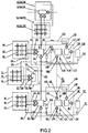
- the primary system of the district public water supply pipe network compatible for the source side water for ground source heat pump system and reclaimed water comprises a main water supply pipe 3 connected with the outlet of the sewage treatment system, which is the transportation medium in the pipe network, i.e. the main pipeline for transporting both the source side water and reclaimed water and is configured to transport the source side water and reclaimed water to each energy station and each transmission and distribution station.
- Plurality of energy stations 13/22 are connected with main water supply pipe 3, and a water return main pipe 19 is arranged between the adjacent energy stations 13/22 to communicate them, and each energy station 13/22 is provided with plurality of shallow geothermal energy exchange systems 14/21, 17/25exchanging heat with shallow geothermal energy source in the region.
- Each energy station 13/22 is connect with a corresponding distribution pipe network 61/44, each of which is connected with one or more user side water supply systems.
- each energy station 13/22 is connected with the water supply pipe of distribution pipe network corresponding to the energy station through distribution water pump 59/46 and water supply distribution pipe of distribution pipe network 60/47 in sequence, and that each energy station 13/22 is connected with the water return pipelines of corresponding distribution pipe network 61/44 through water return distribution pipe 55/48/49.
- Energy station 13/22 comprises a distribution pool 4/43, a collection pool 8/34 and a reclaimed water treatment system 11/29.
- distribution pool 4/43 is connected with main water supply pipe 3, from which distribution pool 4/43 receives both the source side water and reclaimed water.
- Outlet C"/F" at the distribution side of the energy station is connected with water supply distribution pipe 60/47 in corresponding distribution pipe network 61/44 by an distribution water pump 59/46 of energy station.
- Inlet a'/d' of collection pool 8/34 is connected with water return distribution pipe 55/48, and the outlet of collection pool 8/34 is connected with the inlet of reclaimed water treatment system 11/29.
- Reclaimed water treatment system 11/29 is configured to have two outlets.
- one of the outlets is connected with the inlet of shallow geothermal energy exchange system 14/21 corresponding to energy station 13/22, and the outlet of shallow geothermal energy system 14/21 is connect to a first inlet B'/E' of distribution pool 4/43 through outlet pipe of shallow geothermal energy exchange system12/20.
- the other outlet of reclaimed water treatment system 11/29 is connected by a circulating water 16/24 with the inlet of a shallow geothermal energy exchange system 17/25 with different type from shallow geothermal energy system 14/21, and the outlet of shallow geothermal energy exchange system 17/25 is connected with a second inlet B"/E" of distribution pool 4/43 by an outlet pipe 18/26 and the reclaimed water retreatment system 156/157 installed thereon.
- Inlet A of main water supply pipe 3 is connected with a water supply pump for main water supply pipe at the reclaimed water outlet of sewage treatment system 1.
- Outlet B of main water supply pipe 3 is connected with an inlet of distribution pool 4 of first energy station 13.
- Water supply pump 5 of main water supply pipe which is mounted at outlet C' of distribution pool 4 in first energy station 13 is connected with inlet C of the next section of main water supply pipe 3.
- Outlet E of the next section of main water supply pipe 3 is connected with inlet of distribution pool 43 in second energy station 11.
- Water supply pump 43 installed at the outlet of distribution pool 43 of second energy station 11 is connected with an inlet E of the next section of main water supply pipe 3, and so on until the last energy station.
- Water return main pipe 19 is arranged between collection pools 8 and 34 of adjacent energy stations 13/22, which is configured to transport water by pressure and in both directions.
- Return connector a of collection pool 8 of the previous energy station is connected with head port b of water return main pipe 19 through return water pump for water return main pipe 10 and control valve for water return main pipe 9 in sequence.
- Tail port c of water return main pipe 19 is connected with first return connector d of collection pool 34 of the next energy station through control valve for water return main pipe 31 and return water pump for water return main pipe 30 in sequence.
- Second return connector d of collection pool 34 is connected with head port f of the next section of water return main pipe 19 through return water pump for water return main pipe 28 and control valve for water return main pipe 27 in sequence, and so on until the last energy station.
- head port b/f and tail port c of each water return main pipe 19 are connected with corresponding collection pool 8/34 respectively by bypass valves 7/36/33 and bypass pipe 6/35/32.
- the distribution side of distribution pool 4/43 of each energy station 13/22 is connected with corresponding distribution pipe network 61/44.
- the outlet C"/F" at the distribution side of distribution pool 4/43 of each energy station 13/22 is connected with water supply branch pipe 62/51 of corresponding distribution pipe network 61/44 through distribution water pump 59/46 and water supply distribution pipe 60/47 in sequence.
- the inlet a'/d' of the collection pool 8/34 of the energy station 13/22 is connected with the distribution pipe network water return branch pipe 58/45 of the corresponding distribution pipe network 61/44, which is a hybrid pipe network with both ring-shape network and branched network.
- the water return pipelines of distribution pipe network 61/44 transport the return water by gravity force, pressure force or the combination of both.
- the water supply branch pipe 62/51 and water return branch pipe 58/45 of distribution pipe network 61/44 are connected with one or more user side water supply systems respectively.
- Transmission and distribution stations are arranged in accordance with the layout of pipe network and the load demand at user side.
- the transmission and distribution stations is the distribution element in the pipe networks, which distribute the transmission medium in the pipe network (i.e. the source side water and reclaimed water) to each user terminal effectively, safely, reasonably and constantly, in accordance with the load demand, load variation of the source side water and reclaimed water in the service region.
- Main water supply pipe 3 is connected with plurality of transmission and distribution stations 38.
- the distribution side of each transmission and distribution stations 38 is connected with distribution pipe network 56.
- Transmission and distribution station 38 comprises distribution pool 39, distribution water pump 53 and control valve 41.
- Inlet pipe 40 of distribution pool 39 of transmission and distribution station is connected with main water supply pipe 3 at point D by control valve 41 so that it may receive the source side water and reclaimed water.
- Outlet D' at the distribution side of distribution pool 39 is connected with water supply branch pipe 57 of the corresponding distribution pipe network 56 through distribution water pump 53 and water supply distribution pipe 54 in sequence.
- Water return branch pipe 52 of distribution pipe network 56 is connected with water return distribution pipe 49/48 of distribution pipe network 44 corresponding to energy station 11 which is adjacent to distribution pipe network 56 by a water return distribution pipe 50.
- Water return distribution pipe 48 of distribution pipe network is connected with inlet d' of corresponding collection pool 34 by a booster pump for water return pipeline 37.
- water supply branch pipe 57 and water return branch pipe 52 of distribution pipe network 56 are connected with one or more user side water supply systems respectively.
- one of water supply branch pipes 62/51/57 of distribution pipe network 61/44/56 is connected with the energy station 13/22 or transmission or distribution station 38 is used as main water supply pipe 65 of sub-district pipe network in the district public water supply pipe network system compatible for source side water for ground source heat pump system and reclaimed water.
- the main water supply pipe 65 of sub-district pipe network is connected with plurality of energy stations 118/105 of sub-district pipe network. Between the collection pools 111 and 94 of adjacent two energy stations 118/105 of sub-district pipe network, there are water return main pipes 91 of the sub-district pipe network connecting both collection pools 111/94.
- Each energy station 118/105 of sub-district pipe network comprises plurality of shallow geothermal energy exchange system of sub-district pipe networks which exchange heat with shallow geothermal source.
- the outlet of collection pool 111/94 of each energy station 118/105 of the sub-district pipe network is connected with the inlet of reclaimed water treatment equipment 115/98 of the sub-district pipe network by pipelines.
- the outlet of reclaimed water treatment equipment 115/98 of the sub-district pipe network is connected with inlets of plurality of shallow geothermal energy exchange system of sub-district pipe networks 119/116/106/97 respectively by circulating water 117/113/99/96 of shallow geothermal energy exchange system of sub-district pipe network.
- the outlets of shallow geothermal energy exchange system of sub-district pipe networks 119/106 are connected with distribution pool 71/87 of energy station 118/105 of the sub-district pipe network by outlet pipes 120/103 of the energy exchange system respectively.
- the outlets of shallow geothermal energy exchange system of sub-district pipe networks 116/97 are connected with distribution pool 71/87 of energy station 118/105 of the sub-district pipe network respectively by outlet pipes 112/95 of the energy exchange system and reclaimed water retreatment system 158/159 mounted thereon.
- Each energy station 118/105 of sub-district pipe network is connected with corresponding sub-district distribution pipe network 66/81.
- outlet g/i at the distribution side of distribution pool 71/87 of each energy station 118/105 of sub-district pipe network is connected with water supply branch pipe 67/82 of corresponding sub-district distribution pipe network 66/81 through distribution water pump 64/85 and water supply distribution pipe 63/84 of sub-district distribution pipe network in sequence.
- the energy station collection pool 111/94 of each energy station 118/105 of sub-district pipe network is connected with water return branch pipe 68/83 of corresponding sub-district distribution pipe network 66/81 by water return distribution pipe 69/86 of sub-district distribution pipe network.
- both the water supply branch pipe 67/82 and water return branch pipe 68/83 of distribution pipe network 66/81 are connected with one or more user side water supply systems respectively.
- Main water supply pipe 65 of sub-district pipe network is also connected with plurality of sub-district transmission and distribution station 80.
- the distribution side of each sub-district transmission and distribution station 80 is connected with sub-district distribution pipe network 74.
- Sub-district transmission and distribution station 80 comprises distribution pool 79, a distribution water pump 78 and control valve 72.
- Inlet pipe 73 of distribution pool 79 is connected with main water supply pipe of sub-district pipe network 65 at point H by control valve 72 of sub-district transmission and distribution station to receive the source side water and reclaimed water.
- Outlet h' at the distribution side of distribution pool 79 is connected with the water supply branch pipe 75 of the corresponding sub-district distribution pipe network 75 through distribution water pump 78 and water supply distribution pipe 77 of sub-district distribution pipe network.
- Water return branch pipe 76 of distribution pipe network 74 connected with sub-district transmission and distribution station 80 is connected with a water return distribution pipe 69 of sub-district distribution pipe network 66 connected with energy station 118 of the sub-district distribution pipe network which is adjacent to sub-district distribution pipe network 74 by water return distribution pipe 70.
- water supply branch pipe 75 and water return branch pipe 76 of distribution pipe network 74 are connected with one or more user side water supply systems respectively.
- plurality of energy stations 13/22, energy station of the sub-district pipe networks 105/118/124, transmission and distribution stations 38, and sub-district transmission and distribution stations 80/126 are connected with each other and extend in a hybrid topology structure of the combination of tree topology, star topology and bus topology, so that the district public water supply pipe network system compatible for source side water for ground source heat pump system and reclaimed water could be constructed.
- the system according to the present invention operates in accordance with the following principles:
- the recycled water from sewage treatment system 1, i.e. the source side water and reclaimed water is pressurized by pump 2 and transported to distribution pool 4 of first energy station 13 through main water supply pipe 3.
- the cooling/heat medium water collected by shallow geothermal energy exchange system 14/17 in the district is transported to distribution pool 4 of first energy station 13.
- a part of the source side water and reclaimed water is transported to distribution pipe network 61 by distribution water pump 59 mounted at outlet C" of distribution pool 4.
- the other part is pressurized by the water supply pump 5 for the main water supply pipe 3 and transported to transmission and distribution station 38.
- a part of the source side water and reclaimed water is transported to distribution pool 39 of transmission and distribution station 38 from point D of main water supply pipe 3 and through inlet pipe 40 of the transmission and distribution station the source side water and reclaimed water input is transported to distribution pipe network 56 by distribution water pump 53 at distribution side D' of distribution pool 39.
- the other part of the source side water and reclaimed water in main water supply pipe 3 is transported to distribution pool 39 of second energy station 11 through main water supply pipe 3.
- Second energy station 11 adopts the same operation manner with that of first energy station 13, in which the cooling/heat medium water collected by shallow geothermal energy exchange system 21/25 in the district is transported to distribution pool 43 of second energy station 11. After mixture, a part of the source side water and reclaimed water is transported to distribution pipe network 44 by distribution water pump 46 mounted at distribution side F" of energy station distribution pool 43. The other part is pressurized by water supply pump 5 for main water supply pipe at point F of main water supply pipe 3 and transported to the distribution pool of next transmission and distribution station or energy station, and so on.
- Water return branch pipe 58/45/52 of distribution pipe network 61/44/56 is configured to transport the source side water which has circulated in the water source heat pump units of the user terminal in the district back to collection pool 8/34 of energy station 13/22 through water return distribution pipe 55/49/48/50.
- the source side water is treated by reclaimed water treatment system 11/29 in the energy station, and then transported to respective shallow geothermal energy exchange system 14/21,17/25 to exchange heat.
- the refreshed source side water obtained after the heat exchange is transported back to distribution pool 4/43 to circulate.
- the sub-district pipe network operate according to the same principle.
- a water supply system may be established.
- the user side water supply system could not only make full use of the energy contained in the transmission medium (source side water and reclaimed water) in the district public water supply pipe network system compatible for the source side water for ground source heat pump and reclaimed water to provide cooling/heat source for any district user's water source heat pump units, but also participate in the thermal cycle, in which the source side water after energy exchange could be used as the users' reclaimed water source, as non-potable water, for miscellaneous purposes.
- the user side water supply system for the district public water supply pipe network system compatible for the source side water for ground source heat pump system and reclaimed water.
- the first form the user side water supply system provides source side water and reclaimed water to users who use centralized ground source heat pump HVAC system.
- the second form the user side water supply system provides source side water and reclaimed water to the users who use distributed ground source heat pump HVAC system.
- the third form the user side water supply system provides source side water and reclaimed water to the users who only use reclaimed water and do not use ground source heat pump HVAC system.
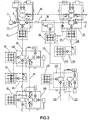
- the user side water supply system of the district public water supply pipe network system compatible for the source side water for ground source heat pump system and reclaimed water comprises water supply branch pipe 62/51/57/67/75/82, water return branch pipe 58/45/52/68/76/83, on which the first form of user side water supply system with the centralized ground source heat pump HVAC system, the second form of user side water supply system with the distributed ground source heat pump HVAC system, and the third form of user side water supply system with the reclaimed water only are respectively installed.
- each of water supply branch pipe 62/51/57/67/75/82 is respectively connected with first water supply sub-branch pipe 128a of the first user side water supply system through first water supply port A which supplies the source side water and reclaimed water to the first user side water supply system, with second water supply sub-branch pipe 128b of the second user side water supply system through second water supply port B which supplies the source side water and reclaimed water to the second user side water supply system, with third water supply sub-branch pipe 128c of the third user side water supply system through second water supply port C which supplies the source side water and reclaimed water to the second user side water supply system.
- first water return sub-branch pipe 129a connected with the first user side water supply system and second water return sub-branch pipe 129b connected with the second user side water supply system are installed.
- Water return branch pipe 58/45/52/68/76/83 is connect with fourth water supply pipe 155 the third user side water supply system through the fourth water supply port D to receive source side back water.
- the first user side water supply system comprises first booster water supply pump 130a connected with first water supply sub-branch pipe 128a, the outlets of which are respectively connected with first source side water inlet sub-branch pipe 135a and first reclaimed water sub-branch pipe 138a.
- the outlet of first source side water inlet sub-branch pipe 135a is connected with the inlet of centralized water source heat pump units 132, the outlet of which is connected with the inlet of first reclaimed water treatment equipment 133a.
- the outlet of first reclaimed water treatment equipment 133a is connected with first inlet f of first reclaimed water tank 140a through first source side water outlet water pump 136a.
- Return port g of first reclaimed water tank 140a is connected with water return branch pipe 58/45/52/68/76/83 of the distribution pipe network through a first water return pipe 129a for source side water and a first source side water return element connected thereon.
- the outlet of first reclaimed water sub-branch pipe 138a is connected with second inlet e of first reclaimed water tank 140a.
- Outlet h of first reclaimed water tank 140a is connected with first reclaimed water supply element through first reclaimed water distribution pipe 142a and first reclaimed water pump 141a installed thereon.
- the first reclaimed water supply element comprises one or more outlets on first reclaimed water distribution pipe 142a and reclaimed water branch pipe for first user side water supply system 144a connected with each outlet of the first reclaimed water distribution pipe 142a.
- One or more first reclaimed water user terminals 143a are installed on each reclaimed water branch pipe for first user side water supply system 144a.
- the first source side water return element comprises first gravity water return pipe 129a-1 and first pressure water return pipe 129a-2, which are parallel to each other and both connected with first water return sub-branch pipe 129a.
- the terminal outlet of first water return sub-branch pipe 129a is connected with water return branch pipe of distribution pipe network 58/45/52/68/76/83.
- Fourth control valve 134a is installed on first gravity water return pipe 129a-1, and fifth control valve 147a, first return water pump 146a and first return check valve 145a are installed on first pressure water return pipe 129a-2 in sequence along the flow direction.
- return port g of first reclaimed water tank140a is connected with the water return branch pipe of distribution pipe network 58/45/52/68/76/83 through first water return sub-branch pipe 129a, first pump 146a and first return check valve 145a both installed on first pressure water return pipe 129a-2 in sequence.
- first reclaimed water tank 140a When operating in gravity return mode, return port g of first reclaimed water tank 140a is connected with water return branch pipe of the distribution pipe network 58/45/52/68/76/83 through first water return sub-branch pipe 129a and first gravity water return pipe 129a-1.
- first control valve 131a is installed on first source side water inlet sub-branch pipe 135a.
- Second control valve 139a is installed on the first reclaimed water sub-branch pipe 138a.
- Third control valve 137a is installed on the pipeline connecting first source side outlet water sub-branch pipe 136a and first reclaimed water tank 140a.
- the second user side water supply system comprises a second booster water supply pump 130b connected with second water supply sub-branch pipe 128b, the outlet of which is respectively connected with second source side water inlet sub-branch pipe 135b and second reclaimed water sub-branch pipe 138b.
- Each outlet is connected with source side water inlet pipe 150.
- Each source side water inlet pipe 150 is connected with one or more inlets of distributed water source heat pump units 149.
- the outlet of each distributed water source heat pump units 149 is connected with the inlet of corresponding source side water outlet pipe 148.
- the outlets of plurality of source side water outlet pipes 148 is connected with the inlet of source side water outlet header pipe 151.
- the outlet of source side water outlet header pipe 151 is connected with the inlet of second reclaimed water treatment equipment 133b.
- the outlet of second reclaimed water treatment equipment 133b is connected with first inlet f of second reclaimed water tank 140b through a second source side water outlet pump 136b.
- Return port g of second reclaimed water tank 140b is connected with water return branch pipe 58/45/52/68/76/83 of the distribution pipe network through second water return sub-branch pipe 129b and second return element connected thereon.
- the outlet of second reclaimed water sub-branch pipe 138b is connected with second inlet e of second reclaimed water tank 140b.
- Outlet h of second reclaimed water tank 140b is connected with a second reclaimed water supply element through second reclaimed water distribution pipe 142b and second reclaimed water pump 141b installed thereon.
- the second reclaimed water supply element comprises one or more outlets on second reclaimed water distribution pipe 142b and reclaimed water branch pipe for second user side water supply system 144b connected with each outlet of reclaimed water branch pipe for second user side water supply system 142b respectively.
- One or more second reclaimed water user terminals 143b are installed on each reclaimed water branch pipe for second user side water supply system 144b.
- the second return element comprises second gravity water return pipe 129b-1 and second pressure water return pipe 129b-2, which are parallel to each other and both connected with second water return sub-branch pipe 129b.
- the terminal outlet of second water return sub-branch pipe 129b is connected with water return branch pipe of sub-district distribution pipe network 58/45/52/68/76/83.
- tenth valve 134b is installed on second gravity water return pipe 129b-1.
- Eleventh control valve 147b, second return water pump 146b and second check valve 145b are installed on second pressure water return pipe 129b-2 in sequence along the flow direction.
- return port g of second reclaimed water tank 140b is connected with water return branch pipe of distribution pipe network 58/45/52/68/76/83 through second water return sub-branch pipe 129b and second return water pump 146b and second return check valve 145b both installed thereon in sequence.
- return port g of second reclaimed water tank 140b is connected with water return branch pipe of distribution pipe network 58/45/52/68/76/83 through second pipe 129b and second gravity water return pipe 129b-1.
- sixth control valve 131b is installed on second source side water inlet sub-branch pipe 135b.
- Seventh control valve 139b is installed on second reclaimed water sub-branch pipe 138b.
- Eighth control valve 137b is installed on the pipeline connecting second source side water inlet sub-branch pipe 136b and second reclaimed water tank 140a.
- the outlet of source side water outlet header pipe 151 is connected with the inlet of second reclaimed water treatment equipment 133b through ninth control valve 152.
- the first reclaimed water tank 140a and the second reclaimed water tank 140b may get the water return in gravity return mode or in pressure return mode.
- the mode adopted to get the water return is depended on the pressure in water return branch pipe of distribution pipe networks 58/45/52/68/76/83, first reclaimed water tank 140a and second reclaimed water tank 140b.
- the third user side water supply system comprises third water supply sub-branch pipe 128c and twelfth control valve 153 installed thereon, and fourth water supply sub-branch pipe 155 and thirteenth control valve 154 installed thereon.
- the outlets of third water supply sub-branch pipe 128c and that of fourth water supply sub-branch pipe 155 are both connected with a third reclaimed water supply element together through third reclaimed water distribution pipe 142c and third reclaimed water pump 141c installed thereon.
- the third reclaimed water supply element comprises one or more outlets on third reclaimed water distribution pipe 142c and reclaimed water sub-branch pipe for third reclaimed water user terminal 144c respectively connected with each outlet of the third reclaimed water distribution pipe 142c.
- One or more third reclaimed water user terminals 143c are installed on each reclaimed water sub-branch pipe for third reclaimed water user terminal 144c.
- the original reclaimed water supply pipe in the urban public reclaimed water pipe network in prior art may be used as water supply branch pipe of distribution pipe network 62/51/57/67/75/82 of the present invention.
- the water return branch pipe of the distribution pipe network 58/45/52/68/76/83 of the district public water supply pipe network system compatible for the source side water for ground source heat pump system and reclaimed water need adopts the secondary reclaimed water supply pipe specifically built for the system.
- the operation principle of the user side water supply system of the water supply pipe network is as follows:
- Third water supply sub-branch pipe 128c receives the source side water and reclaimed water from third water supply port C of water supply branch pipe of distribution pipe network 62/51/57/67/75/82 of the district public water supply pipe network system compatible for the source side water for ground source heat pump system and reclaimed water.
- the received source side water and reclaimed water is transported to the third reclaimed water supply equipment in the third user side water supply system by third reclaimed water pump 141c installed on third reclaimed water distribution pipe 142c as reclaimed water only.
- the original reclaimed water supply pipe in the urban public reclaimed water pipe network in prior art may be used as water supply branch pipe of distribution pipe network 62/51/57/67/75/82 of the present invention.
- water return branch pipe of distribution pipe network 58/45/52/68/76/83 of the district public water supply pipe network system compatible for the source side water for ground source heat pump system and reclaimed water may adopts the secondary reclaimed water supply pipe which is not disclosed in prior art.
Landscapes
- Engineering & Computer Science (AREA)
- Combustion & Propulsion (AREA)
- General Engineering & Computer Science (AREA)
- Mechanical Engineering (AREA)
- Chemical & Material Sciences (AREA)
- Thermal Sciences (AREA)
- Physics & Mathematics (AREA)
- Sustainable Energy (AREA)
- Sustainable Development (AREA)
- Life Sciences & Earth Sciences (AREA)
- Heat-Pump Type And Storage Water Heaters (AREA)
- Sewage (AREA)
- Other Air-Conditioning Systems (AREA)
- Management, Administration, Business Operations System, And Electronic Commerce (AREA)
Claims (17)
- Bezirksrohrnetzsystem zur öffentlichen Wasserversorgung, das mit quellseitigem Wasser für ein Erdreichwärmepumpensystem und zurückgewonnenem Wasser kompatibel ist, umfassend:einen Auslass für zurückgewonnenes Wasser eines Abwasseraufbereitungssystems (1);ein Wasserzufuhrhauptrohr (3), das mit dem Auslass für zurückgewonnenes Wasser eines Wasseraufbereitungssystems (1) verbunden ist;eine Mehrzahl von Energiestationen (13, 22) und Übertragungs- und Verteilungsstationen (38), die mit dem Wasserzufuhrhauptrohr (3) verbunden sind;ein Wasserrückführhauptrohr (19), das zwischen benachbarten Energiestationen (13, 22) angeordnet ist;Verteilungsrohrnetze (44, 56, 61), die mit den entsprechenden Energiestationen (13, 22) bzw. den Übertragungs- und Verteilungsstationen (38) verbunden sind;mindestens ein Zufuhrsystem für benutzerseitiges Wasser, das mit dem entsprechenden Verteilungsrohrnetz verbunden ist;wobei die Energiestation (13, 22) eine Mehrzahl von Untiefenerdwärmeaustauschsystemen (14, 21, 17, 25) umfasst, die dazu ausgelegt sind, Wärme mit Untiefenerdwärmequellen auszutauschen; wobei die Energiestation (13, 22) ferner eine Verteilungsseite umfasst, die einen Auslass umfasst, der Auslass an der Verteilungsseite der Energiestation (13, 22) mit dem Wasserzufuhrhauptrohr (3) des entsprechenden Verteilungsrohrnetzes über eine Verteilungswasserpumpe (46, 53 59) und ein Wasserzufuhrverteilungsrohr (47, 54, 60) des Verteilungsrohrnetzes verbunden ist; wobei die Energiestation (13, 22) mit dem Wasserrückführhauptrohr (19) des entsprechenden Verteilungsrohrnetzes über ein Wasserrückführverteilungssrohr (48, 49, 50, 55) des Verteilungsrohrnetzes verbunden ist.
- Bezirksrohrnetzsystem zur öffentlichen Wasserversorgung, das mit quellseitigem Wasser für ein Erdreichwärmepumpensystem und zurückgewonnenem Wasser kompatibel ist, nach Anspruch 1, wobei die Energiestation (13, 22) Folgendes umfasst:einen Verteilungspool, der mit dem Wasserzufuhrhauptrohr (3) verbunden ist und dessen Auslass an der Verteilungsseite mit dem Wasserzufuhrverteilungsrohr (47, 54, 60) des entsprechenden Verteilungsrohrnetzes über eine Verteilungswasserpumpe (46, 53, 59) der Energiestation verbunden ist;einen Sammelpool mit Einlässen, die mit der Wasserrückführrohrleitung des entsprechenden Verteilungsrohrnetzes verbunden sind, und Auslässen, die mit Einlässen eines Aufbereitungssystems für zurückgewonnenes Wasser über eine Rohrleitung verbunden sind;das Aufbereitungssystem für zurückgeführtes Wasser, das dazu ausgelegt ist, ein oder mehrere Auslässe aufzuweisen, die entsprechend mit einer oder zwei Arten von Untiefenerdwärmeaustauschsystemen (14, 21, 17, 25) über Wasserumwälzpumpen verbunden sind;wobei, wenn er mit einem Untiefenerdwärmeaustauschsystem mit geschossener Schleife (14, 21, 17, 25) verbunden ist, der Auslass des Aufbereitungssystems für zurückgewonnenes Wasser mit dem Einlass des Untiefenerdwärmeaustauschsystems mit geschlossener Schleife (14, 21, 17, 25), das der Energiestation entspricht (13, 22), über die Wasserumwälzpumpe verbunden ist; der Auslass des Untiefenerdwärmeaustauschsystems mit geschlossener Schleife (14, 21, 17, 25) mit dem Einlass des Verteilungspools über Rohrleitungen verbunden ist;wenn er mit einem Untiefenerdwärmeaustauschsystem mit offener Schleife (14, 21, 17, 25) verbunden ist, der Auslass des Aufbereitungssystems für zurückgewonnenes Wasser mit dem Einlass des Untiefenerdwärmeaustauschsystems mit offener Schleife (14, 21, 17, 25), das der Energiestation entspricht (13, 22), über die Wasserumwälzpumpe verbunden ist; der Auslass des Untiefenerdwärmeaustauschsystems mit offener Schleife (14, 21, 17, 25) mit dem Einlass des Verteilungspools über Rohrleitungen und einem daran installierten Aufbereitungssystem für zurückgewonnenes Wasser verbunden ist.
- Bezirksrohmetzsystem zur öffentlichen Wasserversorgung, das mit quellseitigem Wasser für ein Erdreichwärmepumpensystem und zurückgewonnenem Wasser kompatibel ist, nach Anspruch 1, wobei: der Einlass des Wasserzufuhrhauptrohrs (3) mit einer Wasserzufuhrpumpe für ein Wasserzufuhrhauptrohr (3) in dem Auslass von zurückgewonnenem Wasser des Abwasseraufbereitungssystems (1) verbunden ist; der Auslass des Wasserzufuhrhauptrohrs (3) mit einem Einlass des Verteilungspools für das Wasserzufuhrhauptrohr (3) in einer ersten Energiestation verbunden ist, eine Wasserzufuhrpumpe für das Wasserzufuhrhauptrohr (3), die an dem Auslass des Verteilungspools für das Wasserzufuhrhauptrohr (3) in der ersten Energiestation (13, 22) mit dem Einlass des nächsten Abschnitts des Wasserzufuhrhauptrohrs (3) verbunden ist, der Auslass des nächsten Abschnitts der Wasserzufuhrhauptrohr (3) mit dem Einlass des Verteilungspools in einer zweiten Energiestation verbunden ist, eine Wasserzufuhrpumpe für das Wasserzufuhrhauptrohr (3), das an dem Auslass des Verteilungspools in der zweiten Energiestation (13, 22) angebracht ist, mit dem Einlass der nächsten Station des Wasserzufuhrhauptrohrs (3) verbunden ist, und so weiter bis zur letzten Energiestation.
- Bezirksrohmetzsystem zur öffentlichen Wasserversorgung, das mit quellseitigem Wasser für ein Erdreichwärmepumpensystem und zurückgewonnenem Wasser kompatibel ist, nach Anspruch 1, wobei: das Wasserrückführhauptrohr (19) zwischen Sammelpools von zwei benachbarten Energiestationen (13, 22) angeordnet ist; ein Rückführanschlussstück von Sammelpools einer vorhergehenden einen der zwei benachbarten Energiestationen (13, 22) nacheinander mit einem Kopfanschluss des Wasserrückführhauptrohrs (19) über eine Rückführwasserpumpe für das Wasserrückführhauptrohr (19) und ein Steuerventil für Wasserrückführhauptrohr (19) verbunden ist; ein Endanschluss des Wasserrückführhauptrohrs (19) nacheinander mit einem ersten Rückführanschlussstück des Sammelpools der nächsten Energiestation (13, 22) über ein Steuerventil für das Wasserrückführhauptrohr (19) und eine Rückführwasserpumpe für das Wasserrückführhauptrohr (19) verbunden ist, ein zweiter Sammelpool des Anschlussstücks zur Rückführung von quellseitigem Wasser der Energiestation (13, 22) nacheinander mit dem Kopfanschluss des nächsten Abschnitts des Wasserrückführhauptrohrs (19) über eine Rückführwasserpumpe für das Wasserrückführhauptrohr (19) und ein Steuerventil für das Wasserrückführhauptrohr (19) verbunden ist; und so weiter bis zur letzten Energiestation, wobei der Kopfanschluss und der Endanschluss jedes Wasserrückführhauptrohrs (19) jeweils mit einem entsprechendem Sammelpool über Bypassventile und Bypassrohr verbunden sind.
- Bezirksrohmetzsystem zur öffentlichen Wasserversorgung, das mit quellseitigem Wasser für ein Erdreichwärmepumpensystem und zurückgewonnenem Wasser kompatibel ist, nach Anspruch 1, wobei die Übertragungs- und Verteilungsstation Folgendes umfasst:ein Steuerventil;ein Einlassrohr, das mit einem Einlass des Wasserzufuhrhauptrohrs (3) über das Steuerventil verbunden ist;eine Verteilungswasserpumpe (46, 53, 59); undeinen Verteilungspool, dessen Einlass mit einem Auslass des Einlassrohrs verbunden ist, und dessen Auslass an der Verteilungsseite mit dem entsprechenden Verteilungsrohrnetz über die Verteilungswasserpumpe (46, 53, 59) verbunden ist.
- Bezirksrohrnetzsystem zur öffentlichen Wasserversorgung, das mit quellseitigem Wasser für ein Erdreichwärmepumpensystem und zurückgewonnenem Wasser kompatibel ist, nach Anspruch 1, wobei das Verteilungsnetz Folgendes umfasst:ein Wasserzufuhrverteilungsrohr (47, 54, 60), das dazu ausgelegt ist, sich mit dem Auslass an der Verteilungsseite des Verteilungspools der Energiestation (13, 22) oder der Übertragungs-und Verteilungsstation und Wasserzufuhrabzweigrohren des entsprechenden Verteilungsrohrnetzes zu verbinden;eine Verteilungswasserpumpe (46, 53, 59), die an dem Wasserzufuhrverteilungsrohr (47, 54, 60) installiert ist;ein Wasserrückführverteilungssrohr (48, 49, 50, 55), das dazu ausgelegt ist, den Einlass des Sammelpools der Energiestation (13, 22) und ein entsprechendes Wasserrückführabzweigrohr zu verbinden, wenn das Verteilungsrohmetz mit einer Energiestation verbunden ist, und mit der Wasserrückführrohrleitung eines anderen Verteilungsrohrnetzes, das einer Energiestation (13, 22) entspricht, die an das Verteilungsrohmetz angrenzt, verbunden zu werden, wenn das Verteilungsrohmetz mit einer Übertragungs- und Verteilungsstation verbunden ist;Wasserzufuhrabzweigrohre, die mit mindestens einem benutzerseitigen Wasserzufuhrsystem verbunden sind; undWasserrückführabzweigrohre, die mit mindestens einem benutzerseitigen Wasserzufuhrsystem verbunden sind;wobei das Verteilungsrohmetz ein Hybridrohmetz mit sowohl ringförmigem Netz als auch verzweigtem Netz beinhaltet die Wasserrückführrohrleitungen die Rückführung von quellseitigem Wasser mittels Gravitationsrückführung, Druckrückführung oder der Kombination aus beiden erhalten.
- Bezirksrohmetzsystem zur öffentlichen Wasserversorgung, das mit quellseitigem Wasser für ein Erdreichwärmepumpensystem und zurückgewonnenem Wasser kompatibel ist, nach Anspruch 6, wobei, wenn die Wasserrückführrohrleitungen die Rückführung von quellseitigem Wasser mittels Druckrückführung erhalten, eine Druckerhöhungspumpe an der Wasserrückführrohrleitung installiert ist.
- Bezirksrohmetzsystem zur öffentlichen Wasserversorgung, das mit quellseitigem Wasser für ein Erdreichwärmepumpensystem und zurückgewonnenem Wasser kompatibel ist, nach Anspruch 1, ferner umfassend Unterbezirksrohrnetze, die mit den Verteilungsnetzen verbunden sind, die Energiestationen (13, 22) oder Übertragungs- und -verteilungsstationen (38) entsprechen;
wobei das Unterbezirksrohmetz Folgendes umfasst:ein Wasserzufuhrhauptrohr (3) des Unterbezirksrohrnetzes, das mit dem Wasserzufuhrabzweigrohr des Verteilungsnetzes verbunden ist;eine Mehrzahl von Energiestationen (13,22) des Unterbezirksrohmetzes und Unterbezirksübertragungs- und -verteilungsstationen (38), die mit dem Wasserzufuhrhauptrohr (3) verbunden sind;Wasserrückführhauptpumpen (19) des Unterbezirksverteilungsnetzes, die dazu installiert sind, um die Sammelpools benachbarter Energiestationen (13, 22) des Unterbezirksrohmetzes zu verbinden;Unterbezirksverteilungsrohmetze (44, 56, 61), die mit den entsprechenden Energiestationen (13, 22) bzw. den Übertragungs- und Verteilungsstationen (38) des Unterbezirksrohmetzes verbunden sind;mindestens ein Zufuhrsystem für benutzerseitiges Wasser, das mit dem Unterbezirksverteilungsrohrnetz verbunden ist;wobei Rückführwasserpumpen, Steuerventile, Bypassrohre, Bypassventile für dasWasserrückführhauptrohr (19) an sowohl dem Kopfanschluss als auch dem Endanschluss derWasserrückführhauptrohre (19) des Unterbezirksrohmetzes angeordnet sind; der Auslass des Sammelpools mit einem Einlass eines Aufbereitungssystems für zurückgewonnenes Wasser des Unterbezirksrohmetzes über eine Rohrleitung verbunden ist; das Aufbereitungssystem für zurückgewonnenes Wasser, das dazu ausgelegt ist, eine oder mehrere Auslässe aufzuweisen, die entsprechend mit einer oder zwei Arten von Untiefenerdwärmeaustauschsystemen (14, 21, 17, 25) verbunden sind;wobei, wenn er mit einem Untiefenerdwärmeaustauschsystem mit geschossener Schleife (14, 21, 17, 25) verbunden ist, der Auslass der Aufbereitungssystems für zurückgewonnenes Wasser mit dem Einlass des Untiefenerdwärmeaustauschsystems mit geschlossener Schleife (14; 21, 17, 25), das der Energiestation entspricht (13, 22) über die Wasserumwälzpumpe verbunden ist; der Auslass des Untiefenerdwärmeaustauschsystems mit geschlossener Schleife (14, 21, 17, 25) mit dem Einlass des Verteilungspools über Rohrleitungen verbunden ist;wenn er mit einem Untiefenerdwärmeaustauschsystem mit offener Schleife (14, 21, 17, 25) verbunden ist, der Auslass der Aufbereitungssystems für zurückgewonnenes Wasser mit dem Einlass des Untiefenerdwärmeaustauschsystems mit offener Schleife (14, 21, 17, 25), das der Energiestation entspricht (13, 22), über die Wasserumwälzpumpe verbunden ist; der Auslass des Untiefenerdwärmeaustauschsystems mit offener Schleife (14, 21, 17, 25) mit dem Einlass des Verteilungspools über Rohrleitungen und einem daran installierten Aufbereitungssystem für zurückgewonnenes Wasser verbunden ist. - Bezirksrohmetzsystem zur öffentlichen Wasserversorgung, das mit quellseitigem Wasser für ein Erdreichwärmepumpensystem und zurückgewonnenem Wasser kompatibel ist, nach Anspruch 8, wobei die Unterbezirksübertragungs- und -verteilungsstation Folgendes umfasst:ein Steuerventil;ein Einlassrohr, das mit einem Einlass des Wasserzufuhrhauptrohrs (3) des Unterbezirksrohmetzes über das Steuerventil verbunden ist;eine Verteilungswasserpumpe (46, 53, 59), die an dem Wasserzufuhrverteilungsrohr (47, 54, 60) installiert ist;einen Verteilungspool, dessen Einlass mit einem Auslass des Einlassrohrs verbunden ist, und dessen Auslass an der Verteilungsseite mit dem entsprechenden Unterbezirksverteilungsrohrnetz über die Verteilungswasserpumpe (46, 53, 59) verbunden ist.
- Bezirksrohmetzsystem zur öffentlichen Wasserversorgung, das mit quellseitigem Wasser für ein Erdreichwärmepumpensystem und zurückgewonnenem Wasser kompatibel ist, nach Anspruch 8, wobei das Unterbezirksverteilungsrohrnetz Folgendes umfasst:Verteilungswasserpumpen (46, 53, 59) und Wasserzufuhrverteilungsrohre (47, 54, 60) des Unterbezirksveteilungsrohrnetzes, die dazu ausgelegt sind, sich mit einem Auslass an der Verteilungsseite des Verteilungspools der Energiestation (13, 22) des Unterbezirksrohmetzes oder der Unterbezirksübertragungs- und verteilungsstationen (38) und einem Wasserzufuhrabzweigrohr des entsprechenden Unterbezirksverteilungsrohrnetzes zu verbinden;ein Wasserrückführverteilungssrohr (48, 49, 50, 55) des Unterbezirksveteilungsrohrnetzes, das dazu ausgelegt ist, den Einlass des Sammelpools der Energiestation (13, 22) des Unterbezirksrohmetzes und ein entsprechendes Wasserrückführabzweigrohr zu verbinden, wenn das Unterbezirksverteilungsrohrnetz mit einer Energiestation (13, 22) des Unterbezirksrohmetzes verbunden ist, und mit der Wasserrückführrohrleitung eines anderen Verteilungsrohrnetzes, das einer Energiestation (13, 22) entspricht, die an das Verteilungsrohrnetz angrenzt, verbunden zu werden, wenn das Verteilungsrohrnetz mit einer Übertragungs- und Verteilungsstation verbunden ist;Wasserzufuhrabzweigrohre, die mit mindestens einem benutzerseitigen Wasserzufuhrsystem verbunden sind; undWasserrückführabzweigrohre, die mit mindestens einem benutzerseitigen Wasserzufuhrsystem verbunden sind;wobei das Unterbezirksverteilungsrohrnetz Hybridrohrnetz mit sowohl ringförmigem Netz als auch verzweigtem Netz beinhaltet; die Wasserrückführrohrleitungen die quellseitige Wasserrückführung mittels Gravitationsrückführung, Druckrückführung oder der Kombination aus beiden erhalten.
- Bezirksrohrnetzsystem zur öffentlichen Wasserversorgung, das mit quellseitigem Wasser für ein Erdreichwärmepumpensystem und zurückgewonnenem Wasser kompatibel ist, nach Anspruch 10, wobei, wenn die Wasserrückführabzweigrohre die Rückführung von quellseitigem Wasser mittels Druckrückführung erhalten, eine Druckerhöhungspumpe an der Wasserrückführrohrleitung installiert ist.
- Bezirksrohmetzsystem zur öffentlichen Wasserversorgung, das mit quellseitigem Wasser für ein Erdreichwärmepumpensystem und zurückgewonnenem Wasser kompatibel ist, nach Anspruch 1, wobei es sich bei dem Untiefenerdwärmeaustauschsystem (14, 21, 17, 25), das Wärme mit den Bezirkserdwärmequellen austauscht, um ein beliebiges der Folgenden handelt: mit dem Erdreich verbundenes Wärmeaustauschsystem, Grundwasserquellenwärmetauschsystem, Oberflächenwasserquellenwärmetauschsystem und Abwasserquellenwärmetauschsystem; wobei der Bezirksuntiefenerdwärmeaustausch auch ein Wärmetauschsystem für Quellen erneuerbarer Energie, Wärmetauschsystem für Quellen ungenutzter Energie oder Wärmeaustauschsystem für Rest- und Überschussquellen herkömmlicher Energie beinhalten kann.
- Bezirksrohmetzsystem zur öffentlichen Wasserversorgung, das mit quellseitigem Wasser für ein Erdreichwärmepumpensystem und zurückgewonnenem Wasser kompatibel ist, nach Anspruch 1, wobei eine Mehrzahl von Energiestationen (13, 22), Energiestationen (13, 22) des Unterbezirksrohrnetzes, Übertragungs- und Verteilungsstationen (38) und Unterbezirksübertragungs- und -verteilungsstationen (38) miteinander verbunden sind und sich in Hybridtopologiestruktur aus der Kombination von Baumtopologie, Sterntopologie und Bustopologie derart erstrecken, dass das Bezirksrohmetzsystem zur öffentlichen Wasserversorgung, das mit quellseitigem Wasser eines Erdreichwärmepumpensystems und zurückgewonnenem Wasser kompatibel ist, konstruiert werden könnte.
- Bezirksrohmetzsystem zur öffentlichen Wasserversorgung, das mit quellseitigem Wasser für ein Erdreichwärmepumpensystem und zurückgewonnenem Wasser kompatibel ist, nach Anspruch 6, wobei das Zufuhrsystem von benutzerseitigem Wasser Folgendes umfasst:das Wasserzufuhrabzweigrohr und Wasserrückführabzweigrohr des Verteilungsrohrnetzes oder Unterbezirksverteilungsrohrnetzes des Bezirksrohrnetzsystems zur öffentlichen Wasserversorgung, das mit quellseitigem Wasser für ein Erdreichwärmepumpensystem und zurückgewonnenem Wasser kompatibel ist;erste Zufuhrsysteme für benutzerseitiges Wasser mit einem zentralisierten Erdreichwärmepumpen-HVAC-System, zweite Zufuhrsysteme für benutzerseitiges Wasser mit verteilten Erdreichwärmepumpen-HVAC-Systemen und drittes Zufuhrsystem für benutzerseitiges Wasser, das lediglich das zurückgewonnene Wasser zuführt, jeweils an dem Wasserzufuhrabzweigrohr und dem Wasserrückführabzweigrohr installiert sind;wobei jedes der Wasserzufuhrabzweigrohre jeweils mit einem ersten Wasserzufuhrunterabzweigrohr des ersten benutzerseitigen Wasserzufuhrsystems über einen ersten Wasserzufuhranschluss verbunden ist, der das quellseitige Wasser und das zurückgewonnene Wasser dem ersten benutzerseitigen Wasserzufuhrsystem bereitstellt, mit einem zweiten Wasserzufuhrunterabzweigrohr des zweiten benutzerseitigen Wasserzufuhrsystems über einen zweiten Wasserzufuhranschluss, der das quellseitige Wasser und das zurückgewonnene Wasser dem zweiten benutzerseitigen Wasserzufuhrsystem zuführt, mit einem dritten Wasserzufuhrunterabzweigrohr des dritten benutzerseitigen Wasserzufuhrsystems über einen dritten Wasserzufuhranschluss, der das quellseitige Wasser und zurückgewonnene Wasser dem dritten benutzerseitigen Wasserzufuhrsystem zuführt; das Wasserrückführabzweigrohr mit einem vierten Wasserzufuhrunterabzweigrohr in dem dritten benutzerseitigen Wasserzufuhrsystem über einen vierten Wasserzufuhranschluss verbunden ist, der das quellseitige Wasser aus dem Wärmezyklus wieder bereitstellt;an dem Wasserrückführabzweigrohr des Verteilungsrohrnetzes oder Unterbezirksveteilungsrohrnetzes ein erster Rückführanschluss mit einem ersten Wasserrückführunterabzweigrohr des ersten Zufuhrsystems für benutzerseitiges Wasser verbunden ist, und ein zweiter Rückführanschluss mit einem zweiten Rückführrohr für quellseitiges Wasser des zweiten Zufuhrsystems für benutzerseitiges Wasser verbunden ist.
- Bezirksrohrnetzsystem zur öffentlichen Wasserversorgung, das mit quellseitigem Wasser für ein Erdreichwärmepumpensystem und zurückgewonnenem Wasser kompatibel ist, nach Anspruch 14, wobei das erste Zufuhrsystem für benutzerseitiges Wasser eine erste Druckerhöhungswasserzufuhrpumpe umfasst, die mit dem ersten Wasserzufuhrunterabzweigrohr verbunden ist, dessen Auslass jeweils mit einem ersten Einlassunterabzweigrohr für quellseitiges Wasser und einem ersten Unterabzweigrohr für zurückgewonnenes Wasser verbunden ist; der Auslass des ersten Einlassunterabzweigrohrs für quellseitiges Wasser mit dem Einlass der zentralisierten Wasserquellenwärmepumpeneinheiten verbunden ist; der Auslass der zentralisierten Wasserquellenwärmepumpeneinheiten mit dem Einlass einer ersten Aufbereitungsausrüstung für zurückgewonnenes Wasser verbunden ist; der Auslass der ersten Aufbereitungsausrüstung für zurückgewonnenes Wasser mit dem ersten Einlass eines ersten Tanks für zurückgewonnenes Wasser über eine erste Auslasspumpe für quellseitiges Wasser verbunden ist;
der Rückführanschluss des ersten Tanks für zurückgewonnenes Wasser mit dem Wasserrückführabzweigrohr des Veteilungsrohrnetzes über ein erstes Wasserrückführunterabzweigrohr und ein daran installiertes erstes Rückführelement für quellseitiges Wasser verbunden ist; das erste Rückführelement für quellseitiges Wasser ein erstes Gravitationsrückführrohr und ein erstes Druckrückführrohr umfasst, die parallel zueinander verlaufen und beide mit dem ersten Rückführrohr für quellseitiges Wasser verbunden sind; der Endauslass des ersten Wasserrückführunterabzweigrohrs mit dem ersten Rückführanschluss des Wasserrückführabzweigrohrs verbunden ist; wobei ein viertes Steuerventil an dem ersten Gravitationsrückführrohr installiert ist; ein fünftes Steuerventil, eine erste Rückführwasserpumpe und ein erstes Rückführabsperrventil an dem ersten Druckrückführrohr nacheinander entlang der Strömungsrichtung installiert sind;
der Auslass des ersten Unterabzweigrohrs für zurückgewonnenes Wasser mit einem ersten Einlass des Tanks für zurückgewonnenes Wasser verbunden ist; ein Auslass des ersten Tanks für zurückgewonnenes Wasser mit einem ersten Zufuhrelement für zurückgewonnenes Wasser über ein erstes Verteilungsrohr für zurückgewonnenes Wasser und eine daran installierte erste Pumpe für zurückgewonnenes Wasser verbunden ist;
das erste Zufuhrelement für zurückgewonnenes Wasser ein oder mehrere Auslässe an dem ersten Verteilungsrohr für zurückgewonnenes Wasser und Abzweigrohre für zurückgewonnenes Wasser für ein erstes Zufuhrsystem für benutzerseitiges Wasser umfasst, die jeweils mit einem Auslass an dem ersten Verteilungsrohr für zurückgewonnenes Wasser verbunden ist; ein oder mehrere erste Benutzerendvorrichtungen für zurückgewonnenes Wasser an den Abzweigrohren für zurückgewonnenes Wasser für das erste Zufuhrsystem für benutzerseitiges Wasser installiert ist;
ein erstes Steuerventil an dem ersten Einlassunterabzweigrohr für quellseitiges Wasser installiert ist; ein zweites Steuerventil an dem ersten Unterabzweigrohr für zurückgewonnenes Wasser installiert ist; ein drittes Steuerventil an der Rohrleitung installiert ist, die eine erste Auslasspumpe für quellseitiges Wasser und den ersten Tank für zurückgewonnenes Wasser verbindet. - Bezirksrohmetzsystem zur öffentlichen Wasserversorgung, das mit quellseitigem Wasser für ein Erdreichwärmepumpensystem und zurückgewonnenem Wasser kompatibel ist, nach Anspruch 14, wobei das zweite Zufuhrsystem für benutzerseitiges Wasser eine zweite Druckerhöhungswasserzufuhrpumpe umfasst, die mit dem zweiten Wasserzufuhrunterabzweigrohr verbunden ist, dessen Auslass jeweils mit einem zweiten Einlassunterabzweigrohr für quellseitiges Wasser und einem zweiten Unterabzweigrohr für zurückgewonnenes Wasser verbunden ist; mindestens ein Auslass an dem zweiten Einlassunterabzweigrohr für quellseitiges Wasser vorhanden ist; jeder Auslass mit einem Einlassrohr für quellseitiges Wasser verbunden ist; das Einlassrohr für quellseitiges Wasser mit mindestens einem Einlass der verteilten Wasserquellenwärmepumpeneinheiten verbunden ist; der Auslass der verteilten Wasserquellenwärmepumpeneinheiten mit dem Einlass des entsprechenden Auslassrohrs für quellseitiges Wasser verbunden ist; der Auslass des Auslassrohrs für quellseitiges Wasser mit dem Einlass des Auslassvorrohrs für quellseitiges Wasser verbunden ist; der Auslass des Auslassvorrohrs für quellseitiges Wasser mit dem Einlass einer zweiten Wasseraufbereitungsausrüstung für zurückgewonnenes Wasser verbunden ist; der Auslass der zweiten Aufbereitungsausrüstung für zurückgewonnenes Wasser mit dem ersten Einlass eines zweiten Tanks für zurückgewonnenes Wasser über eine zweite Auslasspumpe für quellseitiges Wasser verbunden ist;
der Rückführanschluss des zweiten Tanks für zurückgewonnenes Wasser mit dem Wasserrückführabzweigrohr des Veteilungsrohrnetzes über ein zweites Wasserrückführunterabzweigrohr und ein daran installiertes zweites Rückführelement für quellseitiges Wasser verbunden ist; das zweite Rückführelement für quellseitiges Wasser ein zweites Gravitationsrückführrohr und ein zweites Druckrückführrohr umfasst, die parallel zueinander verlaufen und beide mit dem zweiten Wasserrückführunterabzweigrohr verbunden sind; der Endauslass des zweiten Wasserrückführunterabzweigrohrs mit dem zweiten Rückführanschluss des Wasserrückführabzweigrohrs verbunden ist; wobei ein zehntes Steuerventil an dem zweiten Gravitationsrückführrohr installiert ist; ein elftes Steuerventil, eine zweite Rückführwasserpumpe und ein zweites Rückführabsperrventil an dem zweiten Druckrückführrohr für quellseitiges Wasser nacheinander entlang der Strömungsrichtung installiert sind;
der Auslass des zweiten Unterabzweigrohrs für zurückgewonnenes Wasser mit einem zweiten Einlass des zweiten Tanks für zurückgewonnenes Wasser verbunden ist; der Auslass des zweiten Tanks für zurückgewonnenes Wasser mit einem zweiten Zufuhrelement für zurückgewonnenes Wasser über ein zweites Verteilungsrohr für zurückgewonnenes Wasser und eine daran installierte zweite Pumpe für zurückgewonnenes Wasser verbunden ist; das zweite Zufuhrelement für zurückgewonnenes Wasser ein oder mehrere Auslässe an dem zweiten Verteilungsrohr für zurückgewonnenes Wasser und Abzweigrohre für zurückgewonnenes Wasser für ein zweites Zufuhrsystem für benutzerseitiges Wasser umfasst, die jeweils mit jedem Auslass des zweiten Verteilungsrohrs für zurückgewonnenes Wasser verbunden ist; ein oder mehrere zweite Benutzerendvorrichtungen für zurückgewonnenes Wasser an dem Abzweigrohr für zurückgewonnenes Wasser für ein zweites Zufuhrsystem für benutzerseitiges Wasser installiert sind;
ein sechstes Steuerventil an dem zweiten Einlassunterabzweigrohr für quellseitiges Wasser installiert ist; ein siebtes Steuerventil an dem zweiten Unterabzweigrohr für zurückgewonnenes Wasser installiert ist; ein achtes Steuerventil an der Rohrleitung installiert ist, die eine zweite Auslasspumpe für quellseitiges Wasser mit dem zweiten Tank für zurückgewonnenes Wasser verbindet; der Auslass des Auslassvorrohrs für quellseitiges Wasser mit dem Einlass der zweiten Aufbereitungsausrüstung für zurückgewonnenes Wasser über ein neuntes Steuerventil verbunden ist. - Bezirksrohmetzsystem zur öffentlichen Wasserversorgung, das mit quellseitigem Wasser für ein Erdreichwärmepumpensystem und zurückgewonnenem Wasser kompatibel ist, nach Anspruch 14, wobei das dritte Zufuhrsystem für benutzerseitiges Wasser ein drittes Wasserzufuhrunterabzweigrohr und ein daran installiertes zwölftes Steuerventil und ein viertes Wasserzufuhrunterabzweigrohr und ein daran installiertes dreizehntes Steuerventil umfasst; die Auslässe des dritten Wasserzufuhrunterabzweigrohrs und jenes des vierten Wasserzufuhrunterabzweigrohrs mit einem dritten Zufuhrelement für zurückgewonnenes Wasser miteinander über ein drittes Verteilungsrohr für zurückgewonnenes Wasser und eine daran installierte dritte Pumpe für zurückgewonnenes Wasser verbunden sind;
das dritte Zufuhrelement für zurückgewonnenes Wasser ein oder mehrere Auslässe an dem dritten Verteilungsrohr für zurückgewonnenes Wasser und Abzweigrohr für zurückgewonnenes Wasser für ein drittes Zufuhrsystem für benutzerseitiges Wasser umfasst, die jeweils mit einem Auslass an dem dritten Verteilungsrohr für zurückgewonnenes Wasser verbunden ist; mindestens eine dritte Benutzerendvorrichtung für zurückgewonnenes Wasser an dem Abzweigrohr für zurückgewonnenes Wasser für das dritte Zufuhrsystem für benutzerseitiges Wasser installiert ist.
Applications Claiming Priority (4)
| Application Number | Priority Date | Filing Date | Title |
|---|---|---|---|
| CN201210360617 | 2012-09-21 | ||
| CN 201210574130 CN103061381A (zh) | 2012-12-21 | 2012-12-21 | 区域地源热泵系统源侧水和中水供水管网用户端给水系统 |
| CN201310342126.2A CN103362176B (zh) | 2012-12-21 | 2013-08-06 | 区域地源热泵系统源侧水中水供水管网用户端给水系统 |
| PCT/CN2013/083748 WO2014044186A1 (zh) | 2012-09-21 | 2013-09-18 | 区域地源热泵及中水公共供水管网系统 |
Publications (3)
| Publication Number | Publication Date |
|---|---|
| EP2910693A1 EP2910693A1 (de) | 2015-08-26 |
| EP2910693A4 EP2910693A4 (de) | 2016-07-06 |
| EP2910693B1 true EP2910693B1 (de) | 2018-07-18 |
Family
ID=50340584
Family Applications (1)
| Application Number | Title | Priority Date | Filing Date |
|---|---|---|---|
| EP13839707.0A Not-in-force EP2910693B1 (de) | 2012-09-21 | 2013-09-18 | Mit bodenquellenwärmepumpe und regeneriertem wasser kompatibles wasserversorgungsrohrnetzwerksystem |
Country Status (4)
| Country | Link |
|---|---|
| US (1) | US9797627B2 (de) |
| EP (1) | EP2910693B1 (de) |
| JP (1) | JP6165867B2 (de) |
| WO (1) | WO2014044186A1 (de) |
Families Citing this family (15)
| Publication number | Priority date | Publication date | Assignee | Title |
|---|---|---|---|---|
| MX2018005675A (es) * | 2015-11-04 | 2018-11-09 | E On Sverige Ab | Montaje de consumo local de energia termica y montaje de generador local de energia termica para un sistema de distribucion regional de energia termica. |
| EP3165831A1 (de) * | 2015-11-04 | 2017-05-10 | E.ON Sverige AB | Fernwärme-verteilsystem |
| CN105297829A (zh) * | 2015-11-24 | 2016-02-03 | 汪传发 | 一种多路供水系统 |
| CN106123367B (zh) * | 2016-06-23 | 2019-02-22 | 上海电力学院 | 一种结合太阳能和地热能的天然气地埋管道防冻胀系统 |
| EP3372903A1 (de) * | 2017-03-07 | 2018-09-12 | E.ON Sverige AB | Lokale verbraucheranordnung von wärmeenergie und lokale erzeugeranordnung für wärmeenergie für ein regionales wärmeenergieverteilungssystem |
| CN107388454A (zh) * | 2017-09-13 | 2017-11-24 | 成都四方星科技有限公司 | 闭循环地热中央空调系统 |
| CN109685704B (zh) * | 2019-01-14 | 2023-07-25 | 博拉网络股份有限公司 | 基于vr的管网巡检系统 |
| EP3699498A1 (de) * | 2019-02-21 | 2020-08-26 | E.ON Sverige AB | Verfahren und vorrichtung zur bestimmung einer abweichung in einem wärmeenergiekreislauf |
| CN112032804B (zh) * | 2020-07-27 | 2022-02-22 | 中国地质科学院水文地质环境地质研究所 | 中低温地热梯级开发利用的发电和集中供热系统及方法 |
| CN114718147B (zh) * | 2021-01-04 | 2025-10-31 | 北京橡胶工业研究设计院有限公司 | 一种硫化过热水节能供水系统 |
| CN114353331B (zh) * | 2022-01-27 | 2025-11-25 | 烟台明辉热泵节能科技有限公司 | 一种楼层分区供水系统 |
| CN115031284B (zh) * | 2022-06-27 | 2024-04-09 | 唐山市热力集团有限公司 | 一种地热和地源热泵综合复合供热控制系统 |
| US20240230176A9 (en) * | 2022-10-19 | 2024-07-11 | Arcadis U.S., Inc. | Closed loop chiller system having single pass recycled water loop |
| CN118498430B (zh) * | 2024-07-17 | 2024-09-20 | 深地科学与工程云龙湖实验室 | 用于装配式地铁车站的能源地下结构系统及其分配方法 |
| CN119594605B (zh) * | 2024-12-26 | 2025-11-14 | 中国华电科工集团有限公司 | 一种浅层地源耦合污水源热泵综合能源系统及其运行方法 |
Family Cites Families (21)
| Publication number | Priority date | Publication date | Assignee | Title |
|---|---|---|---|---|
| JPS6443344A (en) * | 1987-08-12 | 1989-02-15 | Univ Tohoku | Vessel for underground chemical reaction |
| JPH1089802A (ja) * | 1996-09-11 | 1998-04-10 | Nkk Corp | 下水保有熱回収装置 |
| JPH11159891A (ja) * | 1997-11-27 | 1999-06-15 | Kubota Corp | 地中熱利用ヒートポンプシステム |
| US6068773A (en) * | 1998-05-01 | 2000-05-30 | Sheaffer International Ltd. | Single-cell wastewater reclamation and reuse system |
| CN1289882C (zh) * | 2001-08-01 | 2006-12-13 | 罗纳德S·埃斯 | 地热空调 |
| JP2003082970A (ja) * | 2001-09-14 | 2003-03-19 | Teruo Yahiro | 浅層地熱エネルギー回収用熱交換器の地中への設置工法及びその穿孔装置 |
| FR2946755A1 (fr) * | 2009-06-11 | 2010-12-17 | Veolia Eau Cie Generale Eaux | Procede de generation de lots d'eau marques. |
| FR2946734B1 (fr) * | 2009-06-11 | 2011-07-01 | Max Duplan | Equipement de chauffage ou de refroidissement comportant une pompe a chaleur geothermique associee a une installation de production de neige de culture |
| CN201582904U (zh) * | 2009-07-10 | 2010-09-15 | 沈阳国惠供热有限公司 | 分布式水源热泵与集中供热联供系统 |
| CN101761991A (zh) | 2009-12-29 | 2010-06-30 | 大连葆光节能空调设备厂 | 污水源热泵系统 |
| CN101818938B (zh) | 2010-04-03 | 2012-06-27 | 宁波奥克斯电气有限公司 | 居住建筑废水水源热泵热水机 |
| CH703162A1 (fr) * | 2010-05-17 | 2011-11-30 | Cosseco Sa | Système de récupération d'énergie rénouvelable. |
| EP2572052B1 (de) * | 2010-05-20 | 2020-12-30 | Essential Water LLC | Verfahren und system zur bereitstellung eines effluens aus mindestens einer wasseraufbereitungsanlage |
| CN102287915B (zh) | 2011-06-23 | 2014-07-02 | 武汉朗肯节能技术有限公司 | 一种废水源热泵高温热水机组热回收装置 |
| CN202188789U (zh) | 2011-07-21 | 2012-04-11 | 杨茂华 | 蓄能污水源引退水系统及应用其的污水源热泵系统 |
| CN202194180U (zh) * | 2011-08-31 | 2012-04-18 | 重庆箱根天源地热科技发展有限公司 | 地热水管网输送系统 |
| CN202304086U (zh) * | 2011-09-27 | 2012-07-04 | 天津好为节能环保科技发展有限公司 | 地表水式地源热泵热水及恒温恒湿空调系统 |
| CN102410671B (zh) | 2011-11-21 | 2016-05-18 | 广东瑞星新能源科技有限公司 | 一种利用高温废水源的热泵系统 |
| JP2013217603A (ja) * | 2012-04-11 | 2013-10-24 | Iai:Kk | 地中熱ヒートポンプ冷暖房システム |
| CN103061381A (zh) * | 2012-12-21 | 2013-04-24 | 刘定国 | 区域地源热泵系统源侧水和中水供水管网用户端给水系统 |
| CN203113425U (zh) * | 2012-09-21 | 2013-08-07 | 刘定国 | 区域地源热泵系统源侧水·中水公共供水管网系统 |
-
2013
- 2013-09-18 EP EP13839707.0A patent/EP2910693B1/de not_active Not-in-force
- 2013-09-18 WO PCT/CN2013/083748 patent/WO2014044186A1/zh not_active Ceased
- 2013-09-18 JP JP2015532289A patent/JP6165867B2/ja not_active Expired - Fee Related
-
2014
- 2014-11-13 US US14/540,327 patent/US9797627B2/en not_active Expired - Fee Related
Non-Patent Citations (1)
| Title |
|---|
| None * |
Also Published As
| Publication number | Publication date |
|---|---|
| JP6165867B2 (ja) | 2017-07-19 |
| US20150083362A1 (en) | 2015-03-26 |
| JP2015530557A (ja) | 2015-10-15 |
| EP2910693A4 (de) | 2016-07-06 |
| EP2910693A1 (de) | 2015-08-26 |
| WO2014044186A1 (zh) | 2014-03-27 |
| US9797627B2 (en) | 2017-10-24 |
Similar Documents
| Publication | Publication Date | Title |
|---|---|---|
| US9797627B2 (en) | District public water supply pipe network system compatible for source side water for ground source heat pump system and reclaomed water | |
| Li et al. | A new type of district heating system based on distributed absorption heat pumps | |
| CN108317582B (zh) | 数据中心冷热联供余热大温差集中供热系统 | |
| CN108105831A (zh) | 一种玻璃厂低温余热回收利用系统 | |
| CN101776316A (zh) | 一种应用地源热泵技术的江南模式系统及其操控方法 | |
| CN106055773A (zh) | 结合热网模型的多区域综合能源系统配置模型的建立方法 | |
| CN101893348B (zh) | 工矿企业利用矿井涌水废热供暖、制冷系统 | |
| CN103528266A (zh) | 双回路三级闭式循环区域能源站系统 | |
| CN208253697U (zh) | 一种蓄热与多级终端用户联合供热的地热供热运行系统 | |
| CN202158688U (zh) | 工矿企业利用矿井涌水废热供暖制冷系统 | |
| CN201582904U (zh) | 分布式水源热泵与集中供热联供系统 | |
| CN212538007U (zh) | 一种地源热泵及空气源热泵供暖冷库补热系统 | |
| CN203113425U (zh) | 区域地源热泵系统源侧水·中水公共供水管网系统 | |
| CN109059084A (zh) | 一种利用城市生活垃圾降解热量的复合热泵系统及方法 | |
| CN210624678U (zh) | 一种储热型地热高效集中供热系统 | |
| CN211977108U (zh) | 一种汽车生产园区能源公辅综合节能系统 | |
| CN107421163A (zh) | 空气电能双级供热制冷系统及供热制冷方法 | |
| CN203010998U (zh) | 双回路三级闭式循环区域能源站系统 | |
| CN102943502B (zh) | 区域地源热泵系统源侧水·中水公共供水管网系统 | |
| CN218469150U (zh) | 一种电厂余热与多种可再生能源蓄冷蓄热互补供能系统 | |
| CN214664757U (zh) | 一种利用地热能与水源热泵能源耦合供暖系统 | |
| CN201476201U (zh) | 分散水环式地源热泵空调系统 | |
| CN215675384U (zh) | 一种建筑补能系统 | |
| CN204958595U (zh) | 将中水作为地铁空调循环冷却水补水的组合处理系统 | |
| CN203240834U (zh) | 一种余热制冷回收利用系统 |
Legal Events
| Date | Code | Title | Description |
|---|---|---|---|
| PUAI | Public reference made under article 153(3) epc to a published international application that has entered the european phase |
Free format text: ORIGINAL CODE: 0009012 |
|
| 17P | Request for examination filed |
Effective date: 20150420 |
|
| AK | Designated contracting states |
Kind code of ref document: A1 Designated state(s): AL AT BE BG CH CY CZ DE DK EE ES FI FR GB GR HR HU IE IS IT LI LT LU LV MC MK MT NL NO PL PT RO RS SE SI SK SM TR |
|
| AX | Request for extension of the european patent |
Extension state: BA ME |
|
| DAX | Request for extension of the european patent (deleted) | ||
| RA4 | Supplementary search report drawn up and despatched (corrected) |
Effective date: 20160602 |
|
| RIC1 | Information provided on ipc code assigned before grant |
Ipc: F25B 30/06 20060101ALI20160527BHEP Ipc: F24J 3/08 20060101ALI20160527BHEP Ipc: E03B 7/02 20060101AFI20160527BHEP Ipc: F24D 17/02 20060101ALI20160527BHEP Ipc: F24D 17/00 20060101ALI20160527BHEP |
|
| GRAP | Despatch of communication of intention to grant a patent |
Free format text: ORIGINAL CODE: EPIDOSNIGR1 |
|
| INTG | Intention to grant announced |
Effective date: 20171127 |
|
| GRAS | Grant fee paid |
Free format text: ORIGINAL CODE: EPIDOSNIGR3 |
|
| GRAA | (expected) grant |
Free format text: ORIGINAL CODE: 0009210 |
|
| AK | Designated contracting states |
Kind code of ref document: B1 Designated state(s): AL AT BE BG CH CY CZ DE DK EE ES FI FR GB GR HR HU IE IS IT LI LT LU LV MC MK MT NL NO PL PT RO RS SE SI SK SM TR |
|
| REG | Reference to a national code |
Ref country code: GB Ref legal event code: FG4D |
|
| REG | Reference to a national code |
Ref country code: CH Ref legal event code: EP |
|
| REG | Reference to a national code |
Ref country code: IE Ref legal event code: FG4D |
|
| REG | Reference to a national code |
Ref country code: AT Ref legal event code: REF Ref document number: 1019517 Country of ref document: AT Kind code of ref document: T Effective date: 20180815 |
|
| REG | Reference to a national code |
Ref country code: DE Ref legal event code: R096 Ref document number: 602013040599 Country of ref document: DE |
|
| REG | Reference to a national code |
Ref country code: FR Ref legal event code: PLFP Year of fee payment: 6 |
|
| PGFP | Annual fee paid to national office [announced via postgrant information from national office to epo] |
Ref country code: FR Payment date: 20180817 Year of fee payment: 6 Ref country code: DE Payment date: 20180815 Year of fee payment: 6 |
|
| REG | Reference to a national code |
Ref country code: NL Ref legal event code: MP Effective date: 20180718 |
|
| REG | Reference to a national code |
Ref country code: LT Ref legal event code: MG4D |
|
| REG | Reference to a national code |
Ref country code: AT Ref legal event code: MK05 Ref document number: 1019517 Country of ref document: AT Kind code of ref document: T Effective date: 20180718 |
|
| PG25 | Lapsed in a contracting state [announced via postgrant information from national office to epo] |
Ref country code: NL Free format text: LAPSE BECAUSE OF FAILURE TO SUBMIT A TRANSLATION OF THE DESCRIPTION OR TO PAY THE FEE WITHIN THE PRESCRIBED TIME-LIMIT Effective date: 20180718 |
|
| PG25 | Lapsed in a contracting state [announced via postgrant information from national office to epo] |
Ref country code: GR Free format text: LAPSE BECAUSE OF FAILURE TO SUBMIT A TRANSLATION OF THE DESCRIPTION OR TO PAY THE FEE WITHIN THE PRESCRIBED TIME-LIMIT Effective date: 20181019 Ref country code: BG Free format text: LAPSE BECAUSE OF FAILURE TO SUBMIT A TRANSLATION OF THE DESCRIPTION OR TO PAY THE FEE WITHIN THE PRESCRIBED TIME-LIMIT Effective date: 20181018 Ref country code: NO Free format text: LAPSE BECAUSE OF FAILURE TO SUBMIT A TRANSLATION OF THE DESCRIPTION OR TO PAY THE FEE WITHIN THE PRESCRIBED TIME-LIMIT Effective date: 20181018 Ref country code: PL Free format text: LAPSE BECAUSE OF FAILURE TO SUBMIT A TRANSLATION OF THE DESCRIPTION OR TO PAY THE FEE WITHIN THE PRESCRIBED TIME-LIMIT Effective date: 20180718 Ref country code: SE Free format text: LAPSE BECAUSE OF FAILURE TO SUBMIT A TRANSLATION OF THE DESCRIPTION OR TO PAY THE FEE WITHIN THE PRESCRIBED TIME-LIMIT Effective date: 20180718 Ref country code: FI Free format text: LAPSE BECAUSE OF FAILURE TO SUBMIT A TRANSLATION OF THE DESCRIPTION OR TO PAY THE FEE WITHIN THE PRESCRIBED TIME-LIMIT Effective date: 20180718 Ref country code: LT Free format text: LAPSE BECAUSE OF FAILURE TO SUBMIT A TRANSLATION OF THE DESCRIPTION OR TO PAY THE FEE WITHIN THE PRESCRIBED TIME-LIMIT Effective date: 20180718 Ref country code: RS Free format text: LAPSE BECAUSE OF FAILURE TO SUBMIT A TRANSLATION OF THE DESCRIPTION OR TO PAY THE FEE WITHIN THE PRESCRIBED TIME-LIMIT Effective date: 20180718 Ref country code: IS Free format text: LAPSE BECAUSE OF FAILURE TO SUBMIT A TRANSLATION OF THE DESCRIPTION OR TO PAY THE FEE WITHIN THE PRESCRIBED TIME-LIMIT Effective date: 20181118 Ref country code: AT Free format text: LAPSE BECAUSE OF FAILURE TO SUBMIT A TRANSLATION OF THE DESCRIPTION OR TO PAY THE FEE WITHIN THE PRESCRIBED TIME-LIMIT Effective date: 20180718 |
|
| REG | Reference to a national code |
Ref country code: CH Ref legal event code: PK Free format text: BERICHTIGUNGEN |
|
| RIC2 | Information provided on ipc code assigned after grant |
Ipc: E03B 7/02 20060101AFI20160527BHEP Ipc: F24J 3/08 20060101ALI20160527BHEP Ipc: F24D 17/02 20060101ALI20160527BHEP Ipc: F25B 30/06 20060101ALI20160527BHEP Ipc: F24D 17/00 20060101ALI20160527BHEP |
|
| PG25 | Lapsed in a contracting state [announced via postgrant information from national office to epo] |
Ref country code: AL Free format text: LAPSE BECAUSE OF FAILURE TO SUBMIT A TRANSLATION OF THE DESCRIPTION OR TO PAY THE FEE WITHIN THE PRESCRIBED TIME-LIMIT Effective date: 20180718 Ref country code: LV Free format text: LAPSE BECAUSE OF FAILURE TO SUBMIT A TRANSLATION OF THE DESCRIPTION OR TO PAY THE FEE WITHIN THE PRESCRIBED TIME-LIMIT Effective date: 20180718 Ref country code: HR Free format text: LAPSE BECAUSE OF FAILURE TO SUBMIT A TRANSLATION OF THE DESCRIPTION OR TO PAY THE FEE WITHIN THE PRESCRIBED TIME-LIMIT Effective date: 20180718 |
|
| REG | Reference to a national code |
Ref country code: DE Ref legal event code: R097 Ref document number: 602013040599 Country of ref document: DE |
|
| PG25 | Lapsed in a contracting state [announced via postgrant information from national office to epo] |
Ref country code: EE Free format text: LAPSE BECAUSE OF FAILURE TO SUBMIT A TRANSLATION OF THE DESCRIPTION OR TO PAY THE FEE WITHIN THE PRESCRIBED TIME-LIMIT Effective date: 20180718 Ref country code: IT Free format text: LAPSE BECAUSE OF FAILURE TO SUBMIT A TRANSLATION OF THE DESCRIPTION OR TO PAY THE FEE WITHIN THE PRESCRIBED TIME-LIMIT Effective date: 20180718 Ref country code: RO Free format text: LAPSE BECAUSE OF FAILURE TO SUBMIT A TRANSLATION OF THE DESCRIPTION OR TO PAY THE FEE WITHIN THE PRESCRIBED TIME-LIMIT Effective date: 20180718 Ref country code: CZ Free format text: LAPSE BECAUSE OF FAILURE TO SUBMIT A TRANSLATION OF THE DESCRIPTION OR TO PAY THE FEE WITHIN THE PRESCRIBED TIME-LIMIT Effective date: 20180718 Ref country code: ES Free format text: LAPSE BECAUSE OF FAILURE TO SUBMIT A TRANSLATION OF THE DESCRIPTION OR TO PAY THE FEE WITHIN THE PRESCRIBED TIME-LIMIT Effective date: 20180718 |
|
| REG | Reference to a national code |
Ref country code: CH Ref legal event code: PL |
|
| PLBE | No opposition filed within time limit |
Free format text: ORIGINAL CODE: 0009261 |
|
| STAA | Information on the status of an ep patent application or granted ep patent |
Free format text: STATUS: NO OPPOSITION FILED WITHIN TIME LIMIT |
|
| PG25 | Lapsed in a contracting state [announced via postgrant information from national office to epo] |
Ref country code: SK Free format text: LAPSE BECAUSE OF FAILURE TO SUBMIT A TRANSLATION OF THE DESCRIPTION OR TO PAY THE FEE WITHIN THE PRESCRIBED TIME-LIMIT Effective date: 20180718 Ref country code: DK Free format text: LAPSE BECAUSE OF FAILURE TO SUBMIT A TRANSLATION OF THE DESCRIPTION OR TO PAY THE FEE WITHIN THE PRESCRIBED TIME-LIMIT Effective date: 20180718 Ref country code: SM Free format text: LAPSE BECAUSE OF FAILURE TO SUBMIT A TRANSLATION OF THE DESCRIPTION OR TO PAY THE FEE WITHIN THE PRESCRIBED TIME-LIMIT Effective date: 20180718 |
|
| REG | Reference to a national code |
Ref country code: BE Ref legal event code: MM Effective date: 20180930 |
|
| 26N | No opposition filed |
Effective date: 20190423 |
|
| GBPC | Gb: european patent ceased through non-payment of renewal fee |
Effective date: 20181018 |
|
| REG | Reference to a national code |
Ref country code: IE Ref legal event code: MM4A |
|
| PG25 | Lapsed in a contracting state [announced via postgrant information from national office to epo] |
Ref country code: LU Free format text: LAPSE BECAUSE OF NON-PAYMENT OF DUE FEES Effective date: 20180918 |
|
| PG25 | Lapsed in a contracting state [announced via postgrant information from national office to epo] |
Ref country code: IE Free format text: LAPSE BECAUSE OF NON-PAYMENT OF DUE FEES Effective date: 20180918 |
|
| PG25 | Lapsed in a contracting state [announced via postgrant information from national office to epo] |
Ref country code: SI Free format text: LAPSE BECAUSE OF FAILURE TO SUBMIT A TRANSLATION OF THE DESCRIPTION OR TO PAY THE FEE WITHIN THE PRESCRIBED TIME-LIMIT Effective date: 20180718 Ref country code: CH Free format text: LAPSE BECAUSE OF NON-PAYMENT OF DUE FEES Effective date: 20180930 Ref country code: LI Free format text: LAPSE BECAUSE OF NON-PAYMENT OF DUE FEES Effective date: 20180930 Ref country code: BE Free format text: LAPSE BECAUSE OF NON-PAYMENT OF DUE FEES Effective date: 20180930 |
|
| PG25 | Lapsed in a contracting state [announced via postgrant information from national office to epo] |
Ref country code: GB Free format text: LAPSE BECAUSE OF NON-PAYMENT OF DUE FEES Effective date: 20181018 |
|
| PG25 | Lapsed in a contracting state [announced via postgrant information from national office to epo] |
Ref country code: MT Free format text: LAPSE BECAUSE OF NON-PAYMENT OF DUE FEES Effective date: 20180918 |
|
| PG25 | Lapsed in a contracting state [announced via postgrant information from national office to epo] |
Ref country code: TR Free format text: LAPSE BECAUSE OF FAILURE TO SUBMIT A TRANSLATION OF THE DESCRIPTION OR TO PAY THE FEE WITHIN THE PRESCRIBED TIME-LIMIT Effective date: 20180718 |
|
| REG | Reference to a national code |
Ref country code: DE Ref legal event code: R119 Ref document number: 602013040599 Country of ref document: DE |
|
| PG25 | Lapsed in a contracting state [announced via postgrant information from national office to epo] |
Ref country code: PT Free format text: LAPSE BECAUSE OF FAILURE TO SUBMIT A TRANSLATION OF THE DESCRIPTION OR TO PAY THE FEE WITHIN THE PRESCRIBED TIME-LIMIT Effective date: 20180718 |
|
| PG25 | Lapsed in a contracting state [announced via postgrant information from national office to epo] |
Ref country code: CY Free format text: LAPSE BECAUSE OF FAILURE TO SUBMIT A TRANSLATION OF THE DESCRIPTION OR TO PAY THE FEE WITHIN THE PRESCRIBED TIME-LIMIT Effective date: 20180718 Ref country code: MC Free format text: LAPSE BECAUSE OF NON-PAYMENT OF DUE FEES Effective date: 20180718 Ref country code: MK Free format text: LAPSE BECAUSE OF NON-PAYMENT OF DUE FEES Effective date: 20180718 Ref country code: HU Free format text: LAPSE BECAUSE OF FAILURE TO SUBMIT A TRANSLATION OF THE DESCRIPTION OR TO PAY THE FEE WITHIN THE PRESCRIBED TIME-LIMIT; INVALID AB INITIO Effective date: 20130918 |
|
| PG25 | Lapsed in a contracting state [announced via postgrant information from national office to epo] |
Ref country code: DE Free format text: LAPSE BECAUSE OF NON-PAYMENT OF DUE FEES Effective date: 20200401 |
|
| PG25 | Lapsed in a contracting state [announced via postgrant information from national office to epo] |
Ref country code: FR Free format text: LAPSE BECAUSE OF NON-PAYMENT OF DUE FEES Effective date: 20190930 |