EP2910459A1 - Radiator shroud structure - Google Patents
Radiator shroud structure Download PDFInfo
- Publication number
- EP2910459A1 EP2910459A1 EP15154101.8A EP15154101A EP2910459A1 EP 2910459 A1 EP2910459 A1 EP 2910459A1 EP 15154101 A EP15154101 A EP 15154101A EP 2910459 A1 EP2910459 A1 EP 2910459A1
- Authority
- EP
- European Patent Office
- Prior art keywords
- radiator
- extending
- extending portion
- shrouds
- main body
- Prior art date
- Legal status (The legal status is an assumption and is not a legal conclusion. Google has not performed a legal analysis and makes no representation as to the accuracy of the status listed.)
- Granted
Links
Images




Classifications
-
- B—PERFORMING OPERATIONS; TRANSPORTING
- B62—LAND VEHICLES FOR TRAVELLING OTHERWISE THAN ON RAILS
- B62J—CYCLE SADDLES OR SEATS; AUXILIARY DEVICES OR ACCESSORIES SPECIALLY ADAPTED TO CYCLES AND NOT OTHERWISE PROVIDED FOR, e.g. ARTICLE CARRIERS OR CYCLE PROTECTORS
- B62J17/00—Weather guards for riders; Fairings or stream-lining parts not otherwise provided for
- B62J17/02—Weather guards for riders; Fairings or stream-lining parts not otherwise provided for shielding only the rider's front
-
- B—PERFORMING OPERATIONS; TRANSPORTING
- B62—LAND VEHICLES FOR TRAVELLING OTHERWISE THAN ON RAILS
- B62J—CYCLE SADDLES OR SEATS; AUXILIARY DEVICES OR ACCESSORIES SPECIALLY ADAPTED TO CYCLES AND NOT OTHERWISE PROVIDED FOR, e.g. ARTICLE CARRIERS OR CYCLE PROTECTORS
- B62J17/00—Weather guards for riders; Fairings or stream-lining parts not otherwise provided for
- B62J17/10—Ventilation or air guiding devices forming part of fairings
-
- B—PERFORMING OPERATIONS; TRANSPORTING
- B62—LAND VEHICLES FOR TRAVELLING OTHERWISE THAN ON RAILS
- B62J—CYCLE SADDLES OR SEATS; AUXILIARY DEVICES OR ACCESSORIES SPECIALLY ADAPTED TO CYCLES AND NOT OTHERWISE PROVIDED FOR, e.g. ARTICLE CARRIERS OR CYCLE PROTECTORS
- B62J23/00—Other protectors specially adapted for cycles
-
- B—PERFORMING OPERATIONS; TRANSPORTING
- B62—LAND VEHICLES FOR TRAVELLING OTHERWISE THAN ON RAILS
- B62J—CYCLE SADDLES OR SEATS; AUXILIARY DEVICES OR ACCESSORIES SPECIALLY ADAPTED TO CYCLES AND NOT OTHERWISE PROVIDED FOR, e.g. ARTICLE CARRIERS OR CYCLE PROTECTORS
- B62J41/00—Arrangements of radiators, coolant hoses or pipes on cycles
Definitions
- the present invention relates to a radiator shroud structure in a saddle-ride type vehicle such as a motorcycle.
- a structure is publicly known in which a saddle-ride type vehicle including front forks supporting a front wheel and a radiator disposed behind the front forks is provided with shrouds covering sides of the radiator and expanding outward toward the front to efficiently take a traveling wind into the radiator and in which front ends of these shrouds are extended to the sides of the front forks and terminal end portions of the front ends are bent inward (see JP 3508949 ).
- the traveling wind taken in from the front to the inside of the shrouds passes by outer surfaces of the front forks, the traveling wind enters the inside of the shrouds with the line of flow being bent outward by the front forks. Accordingly, the traveling wind hits inner surfaces of the shrouds and becomes turbulent in some cases. When the traveling wind becomes turbulent, wind guiding efficiency deteriorates. To prevent this, the wind is desired to be guided while being regulated just behind the front forks.
- the angle of the inner surface in a front portion of each shroud is such an angle that the traveling wind having passed by the front forks hits the inner surface, and it is difficult to improve regulation efficiency.
- terminal portions of the front ends are generally designed to be bent inward as in the aforementioned publicly-known example, no improvement in the regulation efficiency is expected from a degree of bending in such a terminal design.
- an object of the present application is to obtain a shroud structure capable of improving the wind guiding efficiency.
- a first aspect of the present invention provides a radiator shroud structure in a saddle-ride type vehicle including: a pair of left and right front forks (12) by which a front wheel is steerably supported; a radiator (38) which is disposed behind the front forks (12); and a pair of left and right shrouds (40) which cover left and right outer sides of the radiator (38) from a front side to a rear side of the radiator (38), the front forks (12) being disposed between the pair of left and right shrouds (40) in a vehicle width direction, wherein a front end portion (60) of each of the shrouds (40) is disposed in front of an upper portion of the radiator (38) and an outermost portion (70) of each of the shrouds (40) is disposed in front of the radiator (38), and each of the shrouds (40) includes:
- a second aspect of the present invention is the first aspect of the present invention, wherein a boundary portion between the main body portion (52) and the extending portion (50) forms an upper ridge (76) extending upward and rearward from the outermost portion (70) and a lower ridge (78) extending downward and rearward from the outermost portion (70), and the extending portion (50) extends forward from the upper ridge (76) and the lower ridge (78).
- a third aspect of the present invention is the second aspect of the present invention, wherein the extending portion (50) is provided with a slit (66, 68) penetrating the extending portion (50) in the vehicle width direction.
- a fourth aspect of the present invention is the third aspect of the present invention, wherein the slit (66, 68) has an elongated shape and is disposed such that a longitudinal direction of the slit (66, 68) is aligned with the upper ridge (76) or the lower ridge (78).
- a fifth aspect of the present invention is any one of the second to fourth aspects of the present invention, wherein the extending portion (50) is disposed outside a radiator core (38a) of the radiator (38) in a front view.
- each of the shrouds includes the extending portion which extends from the front end portion of the main body portion obliquely forward and inward toward the rear ends of the front forks, the extending portion configured to guide the leg with the outer surface and to regulate the traveling wind with the inner surface.
- the inner surfaces of the extending portions can guide the traveling wind having passed by the outer surfaces of the front forks such that the traveling wind enters the inside of the front portions of the shrouds immediately after passing by the outer surfaces, and send the traveling wind to the radiator after regulating it.
- the front portions of the shrouds are the extending portions bent obliquely inward and extending forward, the front portions of the shrouds can prevent the traveling wind having passed by the front forks from becoming turbulent and regulate the traveling wind. Hence, the wind guiding efficiency can be improved.
- the extending portion since the extending portion extends obliquely inward and forward above and below the outermost portion in the front end portion of the main body portion, the extending portion can guide the traveling wind entering the inside of the shrouds rearward without the traveling wind escaping to the outside and achieve excellent cooling of the radiator.
- the extending portion is provided with the slit penetrating the extending portion in the vehicle width direction, the air can pass through the slit in the vehicle width direction when the vehicle is inclined in the vehicle width direction in cornering. Accordingly, it is possible to reduce the crosswind resistance in inclination of the vehicle and improve operability in cornering even when the size of a surface for guiding the leg of a rider is increased by increasing the size of each shroud. Moreover, employing the slit allows the rider to move his/her leg smoothly along an outer surface of each shroud.
- the slit since the slit has the elongated shape and is disposed such that the longitudinal direction of the slit is aligned with the upper ridge or the lower ridge, the slit can be provided adjacent to the ridge in front of the ridge. Accordingly, particularly in straight running, it is possible to send the traveling wind from the slit to the inside of a recess portion formed in the boundary portion between the main body portion and the extending portion located in a ridge portion and guide the traveling wind in the shrouds toward the radiator in a wide range, thereby achieving excellent cooling efficiency of the radiator.
- the extending portion since the extending portion is disposed outside the radiator core in the front view, the extending portion can be disposed not to cover the front of the radiator core. Accordingly, it is possible to increase the size of the surface for guiding the leg of the rider by increasing the size of each shroud by the extending portion and, at the same time, maximize the amount of the traveling wind directly flowing to the radiator core.
- Figs. 1 to 7 One embodiment is described below based on Figs. 1 to 7 .
- directions of front, rear, left, and right are based on a vehicle to which the present invention is applied, and are shown by the arrows in the drawings as necessary such that the front direction is denoted by Fr, the left direction is denoted by LH, and the right direction is denoted by RH.
- the inner side refers to a vehicle center side and the outer side refers to the opposite side to the vehicle center side.
- Fig. 1 is a motorcycle for motocross which runs on a rough terrain, and is an example of a saddle-ride type vehicle in the present application.
- a rider In the motorcycle for motocross, a rider sometimes puts his/her leg F forward to support the motorcycle while running on a rough terrain.
- a front portion of a vehicle frame 10 supports a front wheel 14 via a pair of left and right front forks 12, and a rear portion of the vehicle frame 10 supports a rear wheel 18 via a rear arm 16.
- Reference numeral 13 denotes a front visor.
- the vehicle frame 10 includes: a head pipe 20 (see Fig. 5 ) provided in a front end portion of the vehicle frame 10 and supporting the front forks 12; a pair of left and right main frames 22 extending obliquely downward toward the rear from the head pipe 20; a pair of left and right pivot frames 24 extending downward from rear end portions of the main frames 22; one down frame 26 extending obliquely downward from the head pipe 20 below the main frames 22; and a pair of left and right under frames 28 connecting the down frame 26 and lower ends of the pivot frames 24 to one another.
- An engine 30 at a center of the vehicle is supported by the vehicle frame 10 between the front wheel 14 and the rear wheel 18.
- the front forks 12 are turnably supported on the head pipe 20 via a top bridge 32 and a bottom bridge 34, and are steered by using a handlebar 36.
- the engine 30 is a water-cooled engine and is cooled by radiators 38 disposed on the front side of the engine 30. Sides of the radiators 38 are covered with shrouds 40. A rear portion of a front fender 42 is disposed inside front portions of the shrouds 40. The rear portion of the front fender 42 extends to the front of the radiators 38.
- the shrouds 40 are members which cover the sides of the radiators 38 and which guides a wind to the radiators 38 to improve cooling efficiency. Moreover, the shrouds 40 are portions where the legs F of the rider may cross when the rider puts his/her legs F forward to support the vehicle while running, and are configured to guide the legs F in this case.
- each of the shrouds 40 overlaps the front forks 12.
- An upper portion of each shroud 40 is fixed to a side surface of a fuel tank 44 with a bolt 40a, the fuel tank 44 being supported by the main frames 22 above the engine 30.
- a lower portion of each shroud 40 is attached to a side portion of the corresponding radiator 38 with a bolt 40b.
- a rear portion of each shroud 40 extends rearward along a lower portion of the fuel tank 44 and is attached to a rear end side portion of the fuel tank 44 with a bolt 40c.
- a seat 46 is disposed behind the fuel tank 44.
- radiators 38 are described by using Figs. 2 to 6 .
- the radiators 38 are provided respectively on left and right sides of the down frame 26.
- An inner portion of each of the radiators 38 is attached to a side surface of the down frame 26 via a rubber member 92 by using a bracket 90 (see Figs. 3 and 6 ).
- the left and right radiators 38 are disposed behind the front forks 12 and the front fender 42 and are disposed in such a state that wind receiving surfaces thereof face forward and that the radiators 38 are inclined to face slightly inward (see Fig. 6 ).
- Inner portions of the front forks 12 are placed in recess portions 42a ( Fig. 4 ) formed in the front fender 42, and the amounts of protrusion from sides of the front fender 42 are thereby reduced.
- the shroud 40 protruding forward is disposed outside each of the radiators 38 to guide a traveling wind WD to the radiator 38. Note that, instead of the radiators 38 provided separately on left and right sides, a radiator in which the left and right radiators are integrated may be used.
- each of the radiators 38 includes a radiator core 38a which is a main body portion and which forms a wind receiving surface for a cooling wind, an upper water tank 38b which is provided on an upper side of the radiator core 38a, and a lower water tank 38c which is provided on a lower side of the radiator core 38a.
- An inlet port is provided in the upper water tank 38b, and a cap 38d is attached to the inlet port.
- the upper water tank 38b is connected to a cylinder of the engine 30 by a hose 39a
- the lower water tank 38c is connected to a water pump of the engine 30 by a hose 39b.
- reference numeral 39c in Fig. 5 denotes a hose connecting the lower water tanks 38c of the left and right radiators to each other.
- a louver 93 is attached to a front face of each of the radiators 38 (see Fig. 5 ).
- the louver 93 is formed by integrating multiple fins 94.
- the fins 94 are inclined to extend obliquely outward and guide the traveling wind WD, guided inward along an inner surface of the shroud 40, toward the radiator core 38a (see Fig. 6 ).
- the outer fin 94 is locked to a locking portion 96a provided in a bracket 96 provided in an outer portion of the radiator 38.
- Figs. 2 to 6 show a state where the front visor 13, the front forks 12, and parts associated therewith are removed.
- Each of the shrouds 40 is molded from a suitable resin and integrally includes an extending portion 50, a main body front portion 52, and a main body rear portion 54.
- the extending portion 50 may be formed separately from the main body front portion 52 and then assembled thereto into one body.
- a portion formed of the main body front portion 52 and the main body rear portion 54 is a main body portion corresponding to a conventional shroud portion.
- the main body front portion 52 and the main body rear portion 54 may be formed integrally or separately.
- the extending portion 50 corresponds to a portion newly added to a front end portion of the main body portion and is a portion formed by partially bending and extending a front portion of the main body front portion 52 forward and inward (see Fig. 3 ).
- An inner surface of the extending portion 50 forms a flow-regulating surface configured to guide the traveling wind to the radiator 38, and an outer surface of the extending portion 50 forms a guide surface configured to guide the leg F of the rider.
- the extending portion 50 is provided in a range of a relatively-small width in an up-down direction which is only an intermediate section of a front end portion of the main body front portion 52 in the up-down direction, and substantially has a sideways V shape in a side view.
- a front-end portion 60 protruding forward is located at a front end of the radiator shroud 40 and is at substantially the same position as rear ends of the front forks 12 in a front-rear direction to laterally overlap the rear ends of the front forks 12. Note that the front-end portion 60 is located to be spaced away from the front forks 12 toward the outer side in a vehicle width direction (see Figs. 4 and 6 ).
- the extending portion 50 extends obliquely forward and inward from the front end portion of the main body front portion 52 toward the rear ends of the front forks 12 in the side view. Note that the position of the front-end portion 60 in the side view only needs to be near the front forks 12, and the front-end portion 60 may be disposed slightly in front of the rear ends of the front forks 12 or be slightly spaced away from the rear ends of the front forks 12 to be disposed therebehind (see Figs. 4 and 6 ).
- the extending portion 50 is a portion in the entire shroud which is frequently used to guide the leg F (see Fig. 1 ) put forward to support the vehicle in running, and includes an upper extending portion 62 extending obliquely upward from the front-end portion 60 toward the rear and a lower extending portion 64 extending obliquely downward from the front-end portion 60 toward the rear.
- Such an operation of the leg F is frequently performed particularly in a vehicle for motocross like one in the embodiment.
- the upper extending portion 62 forms an inclined surface which extends inward toward the upper side in the vehicle, and a slit 66 is formed in the upper extending portion 62.
- the lower extending portion 64 forms an inclined surface which extends inward toward the lower side in the vehicle, and slits 68 are formed to be long in the up-down direction.
- a connection portion between the upper extending portion 62 and the lower extending portion 64 forms a ridge 69 extending rearward from the front-end portion 60, and an rear end portion of the ridge 69 extends to an outermost portion 70 of the main body front portion 52.
- the outermost portion 70 is a portion of the shroud 40 where the amount of lateral protrusion is greatest.
- the front-end portion 60 and the outermost portion 70 are located near and in front of an upper end portion of the radiator 38. Moreover, the front-end portion 60 and the outermost portion 70 are located behind and below the bottom bridge 34 at positions near the bottom bridge 34. The front-end portion 60 and portions near the front-end portion 60 overlap the front forks 12 in the side view. Furthermore, the front-end portion 60 is located in front of and below the outermost portion 70, and the ridge 69 extends obliquely downward toward the front.
- the main body front portion 52 substantially has a sideways V shape in the side view which is larger than the extending portion 50, and includes an upper arm portion 72 extending obliquely upward from the outermost portion 70 toward the rear and a lower arm portion 74 extending obliquely downward from the outermost portion 70 toward the rear.
- the upper arm portion 72 is continuous with the upper extending portion 62 with an upper ridge 76 provided therebetween, and the lower arm portion 74 is continuous with the lower extending portion 64 with a lower ridge 78 provided therebetween.
- the slit 66 has a shape elongated along the upper ridge 76 and penetrates front and back surfaces of the upper extending portion 62 to form an opening larger than the slits 68. Only one slit 66 is provided near the ridge 69.
- the slits 68 extend in an elongated manner along the lower ridge 78 and are arranged side by side in the front-rear direction along the lower ridge 78. A front end portion of the front slit 68 is located near the ridge 69. Each of the slits 68 penetrates front and back surfaces of the lower extending portion 64, and the size thereof is smaller than that of the slit 66.
- the sizes, shapes, and numbers of the slit 66 and the slit 68 can be arbitrary set.
- An upper end portion of the upper arm portion 72 extends onto the side surface of the fuel tank 44, and an attachment portion for the bolt 40a is provided at a distal end of the upper end portion.
- a lower end portion of the lower arm portion 74 extends to a position near a lower end portion of the radiator 38, and an attachment portion for the bolt 40b is provided near the lower end portion.
- the bolt 40b is attached to the bracket 96 (see Fig. 6 ) provided on the outer side of the radiator 38.
- the main body rear portion 54 integrally includes a horizontally-extending portion 80 which extends in the front-rear direction and in which an attachment portion for a bolt 40c (see Fig. 1 ) is provided in a rear end portion and a vertically-extending portion 82 which extends downward from a front end portion of the horizontally-extending portion 80.
- a front end portion 81 of the horizontally-extending portion 80 is inclined slightly and obliquely downward toward the front and is connected to a step portion 75 from a rear side, the step portion 75 formed by a rear end edge portion of the lower arm portion 74 curving forward in an upper portion thereof.
- the position of a front end of the step portion 75 is at about the same height as the outermost portion 70 in the up-down direction, and the front end of the step portion 75 is connected to a lower end of a rear end edge portion of the upper arm portion 72.
- the step portion 75 is a ridge in a connection portion between the front end portion 81 of the horizontally-extending portion 80 and the lower arm portion 74.
- An exhaust opening 84 is formed between the front end portion 81 of the horizontally-extending portion 80 and the rear end edge portion of the upper arm portion 72, and air above the radiator 38 can be exhausted outside from the exhaust opening 84 as shown by the arrow a.
- the vertically-extending portion 82 is connected to a rear end edge portion of the lower arm portion 74 via the ridge 86, and extends downward toward a vicinity of the lower end portion of the lower arm portion 74.
- a rear edge portion of the vertically-extending portion 82 forms a space through which a space behind the radiator 38 is opened to the outside, together with a lower edge portion of the front end portion 81 of the horizontally-extending portion 80. Radiator exhaust air having passed through the radiator 38 inside the shroud 40 is exhausted rearward from this space as shown by the arrow b.
- the front end portions of the shrouds 40 are inclined inward such that an opening is made smaller by the extending portions 50, and each of the front-end portions 60 protrudes inward by a dimension A from the corresponding outermost portion 70.
- each of the shrouds 40 forms a flow-regulating curved surface (see Fig. 6 ) curved to protrude outward.
- the traveling wind WD flows along this flow-regulating curved surface to be changed to an inward flow, and is then guided by the fins 94.
- a lateral width (lateral width in a front projection plane) of each of the radiator cores 38a is expressed as B
- a gap C is formed between the radiator core 38a and the front end portion 60 of the corresponding extending portion 50.
- the front-end portion 60 is disposed outside the outer portion of the radiator core 38a away therefrom by C. Accordingly, a front end 50a of the extending portion 50 is not disposed in front of the radiator core 38a, and the extending portion 50 does not even partially cover the front of the radiator core 38a.
- the front end 50a has a terminal structure slightly bent inward.
- this terminal structure is provided to achieve excellent feeling of touch by not forming an edge in an end edge portion, and does not have a traveling wind guide function with a flow-regulating surface like the extending portion 50.
- the extending portions 50 are bent inward and each of the front end portions 60 protrudes inward from the corresponding outermost portion 70 by the dimension A ( Fig. 4 ), the extending portions 50 are not disposed in front of the radiator cores 38a.
- the area of each of the extending portions 50 in a front view is extremely small, and the extending portions 50 are located outside the radiator cores 38a with small protruding amounts toward the inner sides.
- the length of the lower extending portion 64 of each extending portion 50 in the up-down direction is short, and the lower end of the lower extending portion 64 is at a substantially intermediate portion of the radiator 38 in the up-down direction. Accordingly, a lower portion of the lower extending portion 64 is continuous with the outside fin 94 with part of the lower arm portion 74 provided therebetween. A portion of the lower arm portion 74 other than that visible in Fig. 5 is hidden behind the outside fin 94. Accordingly, as shown in Figs. 2 and 3 , part of the fin 94 is exposed below the extending portion 50 in the side view. This can make the extending portion 50 as small as possible.
- the traveling wind WD passes outside the front forks 12 and the front fender 42 and is guided to the radiators 38 by the shrouds 40 to cool the radiators 38.
- a line of flow of the traveling wind WD is bent outward by the front forks 12 and the front fender 42 near the front forks 12, upon passing outside the front forks 12.
- the traveling wind WD is directly guided by the extending portions 50 to be prevented from becoming turbulent and flows rearward in a regulated state.
- the traveling wind WD can be efficiently guided to the radiator cores 38a.
- each of the extending portions 50 is inclined in an opposite direction to extend inward, the traveling wind WD whose line of flow is bent outward can be smoothly guided.
- each extending portion 50 extends obliquely inward and forward above and below the outermost portion 70 in the front end portion of the main body front portion 52, the extending portion 50 can guide the traveling wind entering the inside of the shrouds 40 rearward without the traveling wind escaping to the outside and achieve excellent cooling of the radiator.
- the extending portions 50 extend inward, the extending portions 50 are provided outside the radiator cores 38a of the radiators 38 so as not to be disposed in front of the radiator cores 38a in the front view. Hence, the amount of the traveling wind WD directly flowing to the radiator cores 38a can be maximized. In addition, since the front of the radiator cores 38a is opened without being covered, it is possible to secure a wind guiding space as large as a wind receiving area in front of the radiator cores 38a and prevent reduction in the amount of wind to be taken in.
- providing the extending portions 50 can increase the sizes of the guide surfaces for the legs F.
- increasing the areas of the guide surfaces of the shrouds 40 does not affect movement of the legs F.
- the guide surfaces form inward-curved surfaces, the movement of the legs F is facilitated. Accordingly, it is possible to increase the sizes of the surfaces for guiding the legs of the rider by increasing the sizes of the shrouds 40 by the extending portions 50 and, at the same time, maximize the amount of the traveling wind flowing directly to the radiator cores 38a.
- the structure of the shrouds 40 having the extending portions 50 is preferable for a motocross vehicle having a front portion in which the legs F are frequently guided.
- Fig. 7 is a horizontal cross-sectional view schematically showing the extending portion 50. Parts (a) and (b) in the drawing show states in straight running and parts (c) and (d) show states in cornering. Moreover, the cross section is taken along the same portion as that of Fig. 6 .
- the traveling wind WD since the slits 68 are provided in the lower extending portion 64 in this application, as shown in part (b), part of the traveling wind WD enters the bent recess portion 65 from the outside of the lower extending portion 64 through the slits 68 as shown by the arrow d.
- the traveling wind WD entering the inside of the lower extending portion 64 as shown by the arrow e is thus rapidly pushed to flow rearward by the wind shown by the arrow d which has passed through the slits 68. Accordingly, the traveling wind WD is less likely to become turbulent.
- the slits 68 can prevent turbulence and contribute to an increase in the amount of guided wind.
- forming the slits 68 to have the elongated shape, aligning the longitudinal direction of the slits 68 with the lower ridge 78, and providing the slits 68 in an elongated manner in front of the lower ridge 78 can send the traveling wind WD from the slits 68 to the radiators 38 in straight running and also increase the opening area.
- the shroud 40 is also a portion configured to guide the leg F.
- the side area increases. Accordingly, the crosswind resistance becomes large when the vehicle is banked to be leaned in the cornering. For this reason, it has been impossible to achieve both of improvement in guiding of the leg F by extending the front portion of the shroud 40 forward and reduction of the crosswind resistance.
- the invention of the present application can achieve both.
- FIG. 8 shows a portion corresponding to Fig. 2
- Fig. 9 is a front view corresponding to Fig. 5 .
- a shroud 40A of this embodiment is changed from the shroud 40 only in the shape of the extending portion. Accordingly, changed portions are denoted by adding reference symbol A to the same reference numerals as those of the corresponding portions in the aforementioned embodiment, and portions which are not changed are denoted by the same reference numerals as those of the corresponding portions in the aforementioned embodiment.
- a lower extending portion 64A in this embodiment is formed to be larger in size, and a lower end portion of the lower extending portion 64A is enlarged to extend to a portion near the lower end portion of the lower arm portion 74, thereby covering the fin 94 which is exposed below the lower extending portion 64 in Fig. 3 and the like.
- this embodiment is no different from the aforementioned embodiment in that entire extending portions 50A including lower portions of the lower extending portions 64A are located outside the radiator cores 38a in the front view. Forming the lower extending portions 64A as described above can further increase the size of the extending portions 50A.
Landscapes
- Engineering & Computer Science (AREA)
- Mechanical Engineering (AREA)
- Cooling, Air Intake And Gas Exhaust, And Fuel Tank Arrangements In Propulsion Units (AREA)
- Automatic Cycles, And Cycles In General (AREA)
Abstract
Description
- The present invention relates to a radiator shroud structure in a saddle-ride type vehicle such as a motorcycle.
- A structure is publicly known in which a saddle-ride type vehicle including front forks supporting a front wheel and a radiator disposed behind the front forks is provided with shrouds covering sides of the radiator and expanding outward toward the front to efficiently take a traveling wind into the radiator and in which front ends of these shrouds are extended to the sides of the front forks and terminal end portions of the front ends are bent inward (see
JP 3508949 - When the traveling wind taken in from the front to the inside of the shrouds passes by outer surfaces of the front forks, the traveling wind enters the inside of the shrouds with the line of flow being bent outward by the front forks. Accordingly, the traveling wind hits inner surfaces of the shrouds and becomes turbulent in some cases. When the traveling wind becomes turbulent, wind guiding efficiency deteriorates. To prevent this, the wind is desired to be guided while being regulated just behind the front forks.
- However, in the conventional example in which the front ends of the shrouds simply expand outward, the angle of the inner surface in a front portion of each shroud is such an angle that the traveling wind having passed by the front forks hits the inner surface, and it is difficult to improve regulation efficiency. Moreover, although terminal portions of the front ends are generally designed to be bent inward as in the aforementioned publicly-known example, no improvement in the regulation efficiency is expected from a degree of bending in such a terminal design. In view of this, an object of the present application is to obtain a shroud structure capable of improving the wind guiding efficiency.
- For the purpose of solving the above-mentioned problems, a first aspect of the present invention provides a radiator shroud structure in a saddle-ride type vehicle including: a pair of left and right front forks (12) by which a front wheel is steerably supported; a radiator (38) which is disposed behind the front forks (12); and a pair of left and right shrouds (40) which cover left and right outer sides of the radiator (38) from a front side to a rear side of the radiator (38), the front forks (12) being disposed between the pair of left and right shrouds (40) in a vehicle width direction, wherein
a front end portion (60) of each of the shrouds (40) is disposed in front of an upper portion of the radiator (38) and an outermost portion (70) of each of the shrouds (40) is disposed in front of the radiator (38), and
each of the shrouds (40) includes: - a main body portion (52) which has the outermost portion (70) at a front end portion; and
- an extending portion (50) which extends from the front end portion of the main body portion (52) obliquely forward and inward toward rear ends of the front forks (12) in a side view, the extending portion (50) configured to guide a leg with an outer surface and to regulate a traveling wind with an inner surface.
- A second aspect of the present invention is the first aspect of the present invention, wherein
a boundary portion between the main body portion (52) and the extending portion (50) forms an upper ridge (76) extending upward and rearward from the outermost portion (70) and a lower ridge (78) extending downward and rearward from the outermost portion (70), and
the extending portion (50) extends forward from the upper ridge (76) and the lower ridge (78). - A third aspect of the present invention is the second aspect of the present invention, wherein the extending portion (50) is provided with a slit (66, 68) penetrating the extending portion (50) in the vehicle width direction.
- A fourth aspect of the present invention is the third aspect of the present invention, wherein the slit (66, 68) has an elongated shape and is disposed such that a longitudinal direction of the slit (66, 68) is aligned with the upper ridge (76) or the lower ridge (78).
- A fifth aspect of the present invention is any one of the second to fourth aspects of the present invention, wherein the extending portion (50) is disposed outside a radiator core (38a) of the radiator (38) in a front view.
- According to the first aspect of the present invention, each of the shrouds includes the extending portion which extends from the front end portion of the main body portion obliquely forward and inward toward the rear ends of the front forks, the extending portion configured to guide the leg with the outer surface and to regulate the traveling wind with the inner surface. Accordingly, the inner surfaces of the extending portions can guide the traveling wind having passed by the outer surfaces of the front forks such that the traveling wind enters the inside of the front portions of the shrouds immediately after passing by the outer surfaces, and send the traveling wind to the radiator after regulating it. In addition, since the front portions of the shrouds are the extending portions bent obliquely inward and extending forward, the front portions of the shrouds can prevent the traveling wind having passed by the front forks from becoming turbulent and regulate the traveling wind. Hence, the wind guiding efficiency can be improved.
- According to the second aspect of the present invention, since the extending portion extends obliquely inward and forward above and below the outermost portion in the front end portion of the main body portion, the extending portion can guide the traveling wind entering the inside of the shrouds rearward without the traveling wind escaping to the outside and achieve excellent cooling of the radiator.
- According to the third aspect of the present invention, since the extending portion is provided with the slit penetrating the extending portion in the vehicle width direction, the air can pass through the slit in the vehicle width direction when the vehicle is inclined in the vehicle width direction in cornering. Accordingly, it is possible to reduce the crosswind resistance in inclination of the vehicle and improve operability in cornering even when the size of a surface for guiding the leg of a rider is increased by increasing the size of each shroud. Moreover, employing the slit allows the rider to move his/her leg smoothly along an outer surface of each shroud.
- According to the fourth aspect of the present invention, since the slit has the elongated shape and is disposed such that the longitudinal direction of the slit is aligned with the upper ridge or the lower ridge, the slit can be provided adjacent to the ridge in front of the ridge. Accordingly, particularly in straight running, it is possible to send the traveling wind from the slit to the inside of a recess portion formed in the boundary portion between the main body portion and the extending portion located in a ridge portion and guide the traveling wind in the shrouds toward the radiator in a wide range, thereby achieving excellent cooling efficiency of the radiator.
- According to the fifth aspect of the present invention, since the extending portion is disposed outside the radiator core in the front view, the extending portion can be disposed not to cover the front of the radiator core. Accordingly, it is possible to increase the size of the surface for guiding the leg of the rider by increasing the size of each shroud by the extending portion and, at the same time, maximize the amount of the traveling wind directly flowing to the radiator core.
-
Fig. 1 is a right-side view of a motorcycle according to an embodiment. -
Fig. 2 is an enlarged view of a portion around a shroud inFig. 1 . -
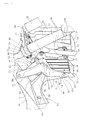
Fig. 3 is a perspective view of a portion around the shroud as viewed obliquely from a front side. -
Fig. 4 is a plan view of a portion around the shrouds. -
Fig. 5 is a front view of radiators and shroud portions. -
Fig. 6 is a cross-sectional view taken along the line 6-6 inFig. 2 . -
Fig. 7 is a view for explaining operations. -
Fig. 8 is a side view of the portion around the shroud in another embodiment. -
Fig. 9 is a front view of the portion around the shroud in the other embodiment. - One embodiment is described below based on
Figs. 1 to 7 . Note that, in the present application, directions of front, rear, left, and right are based on a vehicle to which the present invention is applied, and are shown by the arrows in the drawings as necessary such that the front direction is denoted by Fr, the left direction is denoted by LH, and the right direction is denoted by RH. Moreover, regarding inner and outer sides, the inner side refers to a vehicle center side and the outer side refers to the opposite side to the vehicle center side. -
Fig. 1 is a motorcycle for motocross which runs on a rough terrain, and is an example of a saddle-ride type vehicle in the present application. In the motorcycle for motocross, a rider sometimes puts his/her leg F forward to support the motorcycle while running on a rough terrain. - As shown in
Fig. 1 , in this vehicle, a front portion of avehicle frame 10 supports afront wheel 14 via a pair of left andright front forks 12, and a rear portion of thevehicle frame 10 supports arear wheel 18 via arear arm 16.Reference numeral 13 denotes a front visor. - The
vehicle frame 10 includes: a head pipe 20 (seeFig. 5 ) provided in a front end portion of thevehicle frame 10 and supporting thefront forks 12; a pair of left and rightmain frames 22 extending obliquely downward toward the rear from thehead pipe 20; a pair of left andright pivot frames 24 extending downward from rear end portions of themain frames 22; one downframe 26 extending obliquely downward from thehead pipe 20 below themain frames 22; and a pair of left and right underframes 28 connecting thedown frame 26 and lower ends of thepivot frames 24 to one another. - An
engine 30 at a center of the vehicle is supported by thevehicle frame 10 between thefront wheel 14 and therear wheel 18. Thefront forks 12 are turnably supported on thehead pipe 20 via a top bridge 32 and abottom bridge 34, and are steered by using a handlebar 36. - The
engine 30 is a water-cooled engine and is cooled byradiators 38 disposed on the front side of theengine 30. Sides of theradiators 38 are covered withshrouds 40. A rear portion of afront fender 42 is disposed inside front portions of theshrouds 40. The rear portion of thefront fender 42 extends to the front of theradiators 38. - The
shrouds 40 are members which cover the sides of theradiators 38 and which guides a wind to theradiators 38 to improve cooling efficiency. Moreover, theshrouds 40 are portions where the legs F of the rider may cross when the rider puts his/her legs F forward to support the vehicle while running, and are configured to guide the legs F in this case. - A front end portion of each of the
shrouds 40 overlaps thefront forks 12. An upper portion of eachshroud 40 is fixed to a side surface of afuel tank 44 with abolt 40a, thefuel tank 44 being supported by themain frames 22 above theengine 30. A lower portion of eachshroud 40 is attached to a side portion of thecorresponding radiator 38 with abolt 40b. Moreover, a rear portion of eachshroud 40 extends rearward along a lower portion of thefuel tank 44 and is attached to a rear end side portion of thefuel tank 44 with abolt 40c. Aseat 46 is disposed behind thefuel tank 44. - Here, the
radiators 38 are described by usingFigs. 2 to 6 . Theradiators 38 are provided respectively on left and right sides of thedown frame 26. An inner portion of each of theradiators 38 is attached to a side surface of thedown frame 26 via arubber member 92 by using a bracket 90 (seeFigs. 3 and6 ). - The left and
right radiators 38 are disposed behind thefront forks 12 and thefront fender 42 and are disposed in such a state that wind receiving surfaces thereof face forward and that theradiators 38 are inclined to face slightly inward (seeFig. 6 ). - Inner portions of the
front forks 12 are placed inrecess portions 42a (Fig. 4 ) formed in thefront fender 42, and the amounts of protrusion from sides of thefront fender 42 are thereby reduced. Theshroud 40 protruding forward is disposed outside each of theradiators 38 to guide a traveling wind WD to theradiator 38. Note that, instead of theradiators 38 provided separately on left and right sides, a radiator in which the left and right radiators are integrated may be used. - As shown in
Fig. 2 , each of theradiators 38 includes aradiator core 38a which is a main body portion and which forms a wind receiving surface for a cooling wind, anupper water tank 38b which is provided on an upper side of theradiator core 38a, and alower water tank 38c which is provided on a lower side of theradiator core 38a. An inlet port is provided in theupper water tank 38b, and acap 38d is attached to the inlet port. Theupper water tank 38b is connected to a cylinder of theengine 30 by ahose 39a, and thelower water tank 38c is connected to a water pump of theengine 30 by ahose 39b. Note that reference numeral 39c inFig. 5 denotes a hose connecting thelower water tanks 38c of the left and right radiators to each other. - A
louver 93 is attached to a front face of each of the radiators 38 (seeFig. 5 ). Thelouver 93 is formed by integratingmultiple fins 94. Thefins 94 are inclined to extend obliquely outward and guide the traveling wind WD, guided inward along an inner surface of theshroud 40, toward theradiator core 38a (seeFig. 6 ). Theouter fin 94 is locked to a lockingportion 96a provided in abracket 96 provided in an outer portion of theradiator 38. - Next, the
shrouds 40 are described in detail by usingFigs. 2 to 6 , mainly based onFig. 2 . Note thatFigs. 3 to 5 show a state where thefront visor 13, thefront forks 12, and parts associated therewith are removed. - Each of the
shrouds 40 is molded from a suitable resin and integrally includes an extendingportion 50, a mainbody front portion 52, and a main bodyrear portion 54. However, the extendingportion 50 may be formed separately from the mainbody front portion 52 and then assembled thereto into one body. - A portion formed of the main
body front portion 52 and the main bodyrear portion 54 is a main body portion corresponding to a conventional shroud portion. The mainbody front portion 52 and the main bodyrear portion 54 may be formed integrally or separately. - The extending
portion 50 corresponds to a portion newly added to a front end portion of the main body portion and is a portion formed by partially bending and extending a front portion of the mainbody front portion 52 forward and inward (seeFig. 3 ). An inner surface of the extendingportion 50 forms a flow-regulating surface configured to guide the traveling wind to theradiator 38, and an outer surface of the extendingportion 50 forms a guide surface configured to guide the leg F of the rider. Moreover, the extendingportion 50 is provided in a range of a relatively-small width in an up-down direction which is only an intermediate section of a front end portion of the mainbody front portion 52 in the up-down direction, and substantially has a sideways V shape in a side view. - A front-
end portion 60 protruding forward is located at a front end of theradiator shroud 40 and is at substantially the same position as rear ends of thefront forks 12 in a front-rear direction to laterally overlap the rear ends of thefront forks 12. Note that the front-end portion 60 is located to be spaced away from thefront forks 12 toward the outer side in a vehicle width direction (seeFigs. 4 and6 ). - The extending
portion 50 extends obliquely forward and inward from the front end portion of the mainbody front portion 52 toward the rear ends of thefront forks 12 in the side view. Note that the position of the front-end portion 60 in the side view only needs to be near thefront forks 12, and the front-end portion 60 may be disposed slightly in front of the rear ends of thefront forks 12 or be slightly spaced away from the rear ends of thefront forks 12 to be disposed therebehind (seeFigs. 4 and6 ). - The extending
portion 50 is a portion in the entire shroud which is frequently used to guide the leg F (seeFig. 1 ) put forward to support the vehicle in running, and includes an upper extendingportion 62 extending obliquely upward from the front-end portion 60 toward the rear and a lower extendingportion 64 extending obliquely downward from the front-end portion 60 toward the rear. Such an operation of the leg F is frequently performed particularly in a vehicle for motocross like one in the embodiment. - The upper extending
portion 62 forms an inclined surface which extends inward toward the upper side in the vehicle, and aslit 66 is formed in the upper extendingportion 62. Moreover, in contrast to the upper extendingportion 62, the lower extendingportion 64 forms an inclined surface which extends inward toward the lower side in the vehicle, and slits 68 are formed to be long in the up-down direction. - A connection portion between the upper extending
portion 62 and the lower extendingportion 64 forms aridge 69 extending rearward from the front-end portion 60, and an rear end portion of theridge 69 extends to anoutermost portion 70 of the mainbody front portion 52. Theoutermost portion 70 is a portion of theshroud 40 where the amount of lateral protrusion is greatest. - The front-
end portion 60 and theoutermost portion 70 are located near and in front of an upper end portion of theradiator 38. Moreover, the front-end portion 60 and theoutermost portion 70 are located behind and below thebottom bridge 34 at positions near thebottom bridge 34. The front-end portion 60 and portions near the front-end portion 60 overlap thefront forks 12 in the side view. Furthermore, the front-end portion 60 is located in front of and below theoutermost portion 70, and theridge 69 extends obliquely downward toward the front. - The main
body front portion 52 substantially has a sideways V shape in the side view which is larger than the extendingportion 50, and includes anupper arm portion 72 extending obliquely upward from theoutermost portion 70 toward the rear and alower arm portion 74 extending obliquely downward from theoutermost portion 70 toward the rear. Theupper arm portion 72 is continuous with the upper extendingportion 62 with anupper ridge 76 provided therebetween, and thelower arm portion 74 is continuous with the lower extendingportion 64 with alower ridge 78 provided therebetween. - The
slit 66 has a shape elongated along theupper ridge 76 and penetrates front and back surfaces of the upper extendingportion 62 to form an opening larger than theslits 68. Only one slit 66 is provided near theridge 69. - Meanwhile, two
slits 68 are provided. Theslits 68 extend in an elongated manner along thelower ridge 78 and are arranged side by side in the front-rear direction along thelower ridge 78. A front end portion of the front slit 68 is located near theridge 69. Each of theslits 68 penetrates front and back surfaces of the lower extendingportion 64, and the size thereof is smaller than that of theslit 66. - Note that the sizes, shapes, and numbers of the
slit 66 and theslit 68 can be arbitrary set. - An upper end portion of the
upper arm portion 72 extends onto the side surface of thefuel tank 44, and an attachment portion for thebolt 40a is provided at a distal end of the upper end portion. A lower end portion of thelower arm portion 74 extends to a position near a lower end portion of theradiator 38, and an attachment portion for thebolt 40b is provided near the lower end portion. Thebolt 40b is attached to the bracket 96 (seeFig. 6 ) provided on the outer side of theradiator 38. - The main body
rear portion 54 integrally includes a horizontally-extendingportion 80 which extends in the front-rear direction and in which an attachment portion for abolt 40c (seeFig. 1 ) is provided in a rear end portion and a vertically-extendingportion 82 which extends downward from a front end portion of the horizontally-extendingportion 80. Afront end portion 81 of the horizontally-extendingportion 80 is inclined slightly and obliquely downward toward the front and is connected to astep portion 75 from a rear side, thestep portion 75 formed by a rear end edge portion of thelower arm portion 74 curving forward in an upper portion thereof. - The position of a front end of the
step portion 75 is at about the same height as theoutermost portion 70 in the up-down direction, and the front end of thestep portion 75 is connected to a lower end of a rear end edge portion of theupper arm portion 72. Thestep portion 75 is a ridge in a connection portion between thefront end portion 81 of the horizontally-extendingportion 80 and thelower arm portion 74. - An
exhaust opening 84 is formed between thefront end portion 81 of the horizontally-extendingportion 80 and the rear end edge portion of theupper arm portion 72, and air above theradiator 38 can be exhausted outside from theexhaust opening 84 as shown by the arrow a. - The vertically-extending
portion 82 is connected to a rear end edge portion of thelower arm portion 74 via theridge 86, and extends downward toward a vicinity of the lower end portion of thelower arm portion 74. A rear edge portion of the vertically-extendingportion 82 forms a space through which a space behind theradiator 38 is opened to the outside, together with a lower edge portion of thefront end portion 81 of the horizontally-extendingportion 80. Radiator exhaust air having passed through theradiator 38 inside theshroud 40 is exhausted rearward from this space as shown by the arrow b. - As shown in
Fig. 4 , although theshrouds 40 expand outward toward the front, the front end portions of theshrouds 40 are inclined inward such that an opening is made smaller by the extendingportions 50, and each of the front-end portions 60 protrudes inward by a dimension A from the correspondingoutermost portion 70. - Moreover, each of the
shrouds 40 forms a flow-regulating curved surface (seeFig. 6 ) curved to protrude outward. The traveling wind WD flows along this flow-regulating curved surface to be changed to an inward flow, and is then guided by thefins 94. - As shown in
Fig. 6 , when a lateral width (lateral width in a front projection plane) of each of theradiator cores 38a is expressed as B, a gap C is formed between theradiator core 38a and thefront end portion 60 of the corresponding extendingportion 50. In other words, the front-end portion 60 is disposed outside the outer portion of theradiator core 38a away therefrom by C. Accordingly, afront end 50a of the extendingportion 50 is not disposed in front of theradiator core 38a, and the extendingportion 50 does not even partially cover the front of theradiator core 38a. - Note that the
front end 50a has a terminal structure slightly bent inward. However, this terminal structure is provided to achieve excellent feeling of touch by not forming an edge in an end edge portion, and does not have a traveling wind guide function with a flow-regulating surface like the extendingportion 50. - Moreover, since the extending
portions 50 are bent inward and each of thefront end portions 60 protrudes inward from the correspondingoutermost portion 70 by the dimension A (Fig. 4 ), the extendingportions 50 are not disposed in front of theradiator cores 38a. - Accordingly, as shown in
Fig. 5 , the area of each of the extendingportions 50 in a front view is extremely small, and the extendingportions 50 are located outside theradiator cores 38a with small protruding amounts toward the inner sides. - Furthermore, the length of the lower extending
portion 64 of each extendingportion 50 in the up-down direction is short, and the lower end of the lower extendingportion 64 is at a substantially intermediate portion of theradiator 38 in the up-down direction. Accordingly, a lower portion of the lower extendingportion 64 is continuous with theoutside fin 94 with part of thelower arm portion 74 provided therebetween. A portion of thelower arm portion 74 other than that visible inFig. 5 is hidden behind theoutside fin 94. Accordingly, as shown inFigs. 2 and3 , part of thefin 94 is exposed below the extendingportion 50 in the side view. This can make the extendingportion 50 as small as possible. - Next, operations of the embodiment are described. In
Figs. 4 and6 , the traveling wind WD passes outside thefront forks 12 and thefront fender 42 and is guided to theradiators 38 by theshrouds 40 to cool theradiators 38. - At this time, a line of flow of the traveling wind WD is bent outward by the
front forks 12 and thefront fender 42 near thefront forks 12, upon passing outside thefront forks 12. However, since the extendingportions 50 are located lateral to thefront forks 12 and thefront fender 42, the traveling wind WD is directly guided by the extendingportions 50 to be prevented from becoming turbulent and flows rearward in a regulated state. Hence, the traveling wind WD can be efficiently guided to theradiator cores 38a. - Moreover, since each of the extending
portions 50 is inclined in an opposite direction to extend inward, the traveling wind WD whose line of flow is bent outward can be smoothly guided. - In this case, since each extending
portion 50 extends obliquely inward and forward above and below theoutermost portion 70 in the front end portion of the mainbody front portion 52, the extendingportion 50 can guide the traveling wind entering the inside of theshrouds 40 rearward without the traveling wind escaping to the outside and achieve excellent cooling of the radiator. - Moreover, although the extending
portions 50 extend inward, the extendingportions 50 are provided outside theradiator cores 38a of theradiators 38 so as not to be disposed in front of theradiator cores 38a in the front view. Hence, the amount of the traveling wind WD directly flowing to theradiator cores 38a can be maximized. In addition, since the front of theradiator cores 38a is opened without being covered, it is possible to secure a wind guiding space as large as a wind receiving area in front of theradiator cores 38a and prevent reduction in the amount of wind to be taken in. - Furthermore, providing the extending
portions 50 can increase the sizes of the guide surfaces for the legs F. In this case, increasing the areas of the guide surfaces of theshrouds 40 does not affect movement of the legs F. In addition, since the guide surfaces form inward-curved surfaces, the movement of the legs F is facilitated. Accordingly, it is possible to increase the sizes of the surfaces for guiding the legs of the rider by increasing the sizes of theshrouds 40 by the extendingportions 50 and, at the same time, maximize the amount of the traveling wind flowing directly to theradiator cores 38a. Hence, the structure of theshrouds 40 having the extendingportions 50 is preferable for a motocross vehicle having a front portion in which the legs F are frequently guided. - Moreover, providing the
slit 66 and theslits 68 can increase the amount of guided wind in straight running and reduce crosswind resistance in cornering. This is described by usingFig. 7. Fig. 7 is a horizontal cross-sectional view schematically showing the extendingportion 50. Parts (a) and (b) in the drawing show states in straight running and parts (c) and (d) show states in cornering. Moreover, the cross section is taken along the same portion as that ofFig. 6 . - First, in straight running, when no slits are formed as shown in Part (a), since a
bent recess portion 65 exists between the lower arm portion 74 (main body front portion 52) and the lower extendingportion 64 near thelower ridge 78, the traveling wind WD may become turbulent as shown by the arrow c in thebent recess portion 65 upon entering the inside of the lower extending portion 64 (extending portion 50). - However, since the
slits 68 are provided in the lower extendingportion 64 in this application, as shown in part (b), part of the traveling wind WD enters thebent recess portion 65 from the outside of the lower extendingportion 64 through theslits 68 as shown by the arrow d. The traveling wind WD entering the inside of the lower extendingportion 64 as shown by the arrow e is thus rapidly pushed to flow rearward by the wind shown by the arrow d which has passed through theslits 68. Accordingly, the traveling wind WD is less likely to become turbulent. Hence, theslits 68 can prevent turbulence and contribute to an increase in the amount of guided wind. - Moreover, forming the
slits 68 to have the elongated shape, aligning the longitudinal direction of theslits 68 with thelower ridge 78, and providing theslits 68 in an elongated manner in front of thelower ridge 78 can send the traveling wind WD from theslits 68 to theradiators 38 in straight running and also increase the opening area. - Next, description is given of a case in cornering. When the vehicle is banked in cornering without slits as shown in part (c), the
shroud 40 receives a crosswind f from a side, and the crosswind resistance in leaning of the vehicle becomes relatively large, thereby hindering quick cornering. Meanwhile, as shown in part (d), in a case where theslits 68 exist, since part of the crosswind flows in through theslits 68 from the outside as shown by the arrow g, the crosswind resistance in leaning of the vehicle is reduced. Accordingly, it is possible to reduce the crosswind resistance in leaning of the vehicle and facilitate cornering even in a case where the size of theshroud 40 is increased. - Generally, there is a case where the rider puts his/her leg F forward along an outer surface of the
shroud 40 to support the vehicle in running, and theshroud 40 is also a portion configured to guide the leg F. For the sake of this function, it is desirable to extend a front portion of theshroud 40 forward as much as possible and increase the size of the front portion of theshroud 40. However, when the size of the front portion of theshroud 40 is increased, the side area increases. Accordingly, the crosswind resistance becomes large when the vehicle is banked to be leaned in the cornering. For this reason, it has been impossible to achieve both of improvement in guiding of the leg F by extending the front portion of theshroud 40 forward and reduction of the crosswind resistance. However, the invention of the present application can achieve both. - Moreover, employing the elongated slits allows the leg F to smoothly pass near the
slits 68. - Note that, although this description is about the lower extending
portion 64 and theslits 68 in the extendingportion 50, the same applies to the upper extendingportion 62 and theslit 66. - Next, another embodiment is described based on
Figs. 8 and9 .Fig. 8 shows a portion corresponding toFig. 2 , andFig. 9 is a front view corresponding toFig. 5 . Note that ashroud 40A of this embodiment is changed from theshroud 40 only in the shape of the extending portion. Accordingly, changed portions are denoted by adding reference symbol A to the same reference numerals as those of the corresponding portions in the aforementioned embodiment, and portions which are not changed are denoted by the same reference numerals as those of the corresponding portions in the aforementioned embodiment. - This embodiment is different from the aforementioned embodiment in the following points. In
Figs. 8 and9 , a lower extendingportion 64A in this embodiment is formed to be larger in size, and a lower end portion of the lower extendingportion 64A is enlarged to extend to a portion near the lower end portion of thelower arm portion 74, thereby covering thefin 94 which is exposed below the lower extendingportion 64 inFig. 3 and the like. However, as shown inFig. 9 , this embodiment is no different from the aforementioned embodiment in that entire extendingportions 50A including lower portions of the lower extendingportions 64A are located outside theradiator cores 38a in the front view. Forming the lower extendingportions 64A as described above can further increase the size of the extendingportions 50A. - 10
- VEHICLE FRAME
- 12
- FRONT FORK
- 38
- RADIATOR
- 38a
- RADIATOR CORE
- 40
- SHROUD
- 42
- FRONT FENDER
- 50
- EXTENDING PORTION
- 52
- MAIN BODY FRONT PORTION
- 54
- MAIN BODY REAR PORTION
- 60
- FRONT-END PORTION
- 62
- UPPER EXTENDING PORTION
- 64
- LOWER EXTENDING PORTION
- 66
- SLIT
- 68
- SLIT
- 70
- OUTERMOST PORTION
- 72
- UPPER ARM PORTION
- 74
- LOWER ARM PORTION
- 76
- UPPER RIDGE
- 78
- LOWER RIDGE
Claims (5)
- A radiator shroud structure in a saddle-ride type vehicle including: a pair of left and right front forks (12) by which a front wheel is steerably supported; a radiator (38) which is disposed behind the front forks (12); and a pair of left and right shrouds (40) which cover left and right outer sides of the radiator (38) from a front side to a rear side of the radiator (38), the front forks (12) being disposed between the pair of left and right shrouds (40) in a vehicle width direction, wherein
a front end portion (60) of each of the shrouds (40) is disposed in front of an upper portion of the radiator (38) and an outermost portion (70) of each of the shrouds (40) is disposed in front of the radiator (38), and
each of the shrouds (40) includes:a main body portion (52) which has the outermost portion (70) at a front end portion; andan extending portion (50) which extends from the front end portion of the main body portion (52) obliquely forward and inward toward rear ends of the front forks (12) in a side view, the extending portion (50) configured to guide a leg with an outer surface and to regulate a traveling wind with an inner surface. - The radiator shroud structure according to claim 1, wherein
a boundary portion between the main body portion (52) and the extending portion (50) forms an upper ridge (76) extending upward and rearward from the outermost portion (70) and a lower ridge (78) extending downward and rearward from the outermost portion (70), and
the extending portion (50) extends forward from the upper ridge (76) and the lower ridge (78). - The radiator shroud structure according to claim 2, wherein the extending portion (50) is provided with a slit (66, 68) penetrating the extending portion (50) in the vehicle width direction.
- The radiator shroud structure according to claim 3, wherein the slit (66, 68) has an elongated shape and is disposed such that a longitudinal direction of the slit (66, 68) is aligned with the upper ridge (76) or the lower ridge (78).
- The radiator shroud structure according to any one of claims 2 to 4, wherein the extending portion (50) is disposed outside a radiator core (38a) of the radiator (38) in a front view.
Applications Claiming Priority (1)
| Application Number | Priority Date | Filing Date | Title |
|---|---|---|---|
| JP2014033446A JP6000995B2 (en) | 2014-02-24 | 2014-02-24 | Radiator shroud structure |
Publications (2)
| Publication Number | Publication Date |
|---|---|
| EP2910459A1 true EP2910459A1 (en) | 2015-08-26 |
| EP2910459B1 EP2910459B1 (en) | 2020-07-22 |
Family
ID=52473749
Family Applications (1)
| Application Number | Title | Priority Date | Filing Date |
|---|---|---|---|
| EP15154101.8A Active EP2910459B1 (en) | 2014-02-24 | 2015-02-06 | Radiator shroud structure |
Country Status (2)
| Country | Link |
|---|---|
| EP (1) | EP2910459B1 (en) |
| JP (1) | JP6000995B2 (en) |
Cited By (2)
| Publication number | Priority date | Publication date | Assignee | Title |
|---|---|---|---|---|
| US20220073163A1 (en) * | 2020-09-07 | 2022-03-10 | Suzuki Motor Corporation | Side cowl |
| US11440606B2 (en) * | 2018-03-29 | 2022-09-13 | Honda Motor Co., Ltd. | Straddle-type electric vehicle |
Families Citing this family (1)
| Publication number | Priority date | Publication date | Assignee | Title |
|---|---|---|---|---|
| JP6317726B2 (en) * | 2015-12-18 | 2018-04-25 | 本田技研工業株式会社 | Cowling structure of saddle riding type vehicle |
Citations (3)
| Publication number | Priority date | Publication date | Assignee | Title |
|---|---|---|---|---|
| JP3508949B2 (en) | 1994-08-31 | 2004-03-22 | 本田技研工業株式会社 | Motorcycle wind guide structure |
| EP2230120A1 (en) * | 2009-03-16 | 2010-09-22 | Yamaha Hatsudoki Kabushiki Kaisha | Motorcycle |
| US20130026784A1 (en) * | 2011-07-28 | 2013-01-31 | Honda Motor Co., Ltd. | Saddle-riding type vehicle including multi-part shroud |
Family Cites Families (4)
| Publication number | Priority date | Publication date | Assignee | Title |
|---|---|---|---|---|
| JP2007131257A (en) * | 2005-11-14 | 2007-05-31 | Yamaha Motor Co Ltd | Motorcycle |
| JP5312976B2 (en) * | 2009-02-19 | 2013-10-09 | 本田技研工業株式会社 | Motorcycle |
| JP2011011570A (en) * | 2009-06-30 | 2011-01-20 | Kawasaki Heavy Ind Ltd | Front cowling for motorcycle |
| JP5883716B2 (en) * | 2012-04-26 | 2016-03-15 | 本田技研工業株式会社 | Wind guide structure of saddle-ride type vehicle |
-
2014
- 2014-02-24 JP JP2014033446A patent/JP6000995B2/en active Active
-
2015
- 2015-02-06 EP EP15154101.8A patent/EP2910459B1/en active Active
Patent Citations (3)
| Publication number | Priority date | Publication date | Assignee | Title |
|---|---|---|---|---|
| JP3508949B2 (en) | 1994-08-31 | 2004-03-22 | 本田技研工業株式会社 | Motorcycle wind guide structure |
| EP2230120A1 (en) * | 2009-03-16 | 2010-09-22 | Yamaha Hatsudoki Kabushiki Kaisha | Motorcycle |
| US20130026784A1 (en) * | 2011-07-28 | 2013-01-31 | Honda Motor Co., Ltd. | Saddle-riding type vehicle including multi-part shroud |
Cited By (3)
| Publication number | Priority date | Publication date | Assignee | Title |
|---|---|---|---|---|
| US11440606B2 (en) * | 2018-03-29 | 2022-09-13 | Honda Motor Co., Ltd. | Straddle-type electric vehicle |
| US20220073163A1 (en) * | 2020-09-07 | 2022-03-10 | Suzuki Motor Corporation | Side cowl |
| US11724763B2 (en) * | 2020-09-07 | 2023-08-15 | Suzuki Motor Corporation | Side cowl |
Also Published As
| Publication number | Publication date |
|---|---|
| EP2910459B1 (en) | 2020-07-22 |
| JP6000995B2 (en) | 2016-10-05 |
| JP2015157563A (en) | 2015-09-03 |
Similar Documents
| Publication | Publication Date | Title |
|---|---|---|
| CN102421662B (en) | motorcycle | |
| JP5771100B2 (en) | Saddle riding vehicle | |
| JP6184103B2 (en) | Saddle riding | |
| US8783399B2 (en) | Saddle-riding type vehicle including multi-part shroud | |
| CN105408194B (en) | Two-wheeled body cover structure | |
| JP6254511B2 (en) | Front fender for saddle-ride type vehicles | |
| US9663175B2 (en) | Front fender structure for saddle-ride type vehicle | |
| JP6147540B2 (en) | Saddle riding | |
| US8662230B2 (en) | Saddle-type vehicle | |
| CN105705409B (en) | Fairing structure of straddle-type vehicle and straddle-type vehicle | |
| US10960753B2 (en) | Saddle riding vehicle | |
| BR102016001020B1 (en) | SIDE COVER STRUCTURE OF VEHICLE TYPE TO MOUNT ON SADDLE | |
| EP2889207B1 (en) | Motorcycle | |
| EP2910459B1 (en) | Radiator shroud structure | |
| EP3599148A1 (en) | Straddled vehicle | |
| EP2543581B1 (en) | Cowl structure of saddle-ride type vehicle | |
| US8887851B2 (en) | Saddle-ride type vehicle | |
| CN215475512U (en) | Saddle-ride type vehicle | |
| JP5932382B2 (en) | Saddle riding vehicle | |
| JP5968866B2 (en) | Saddle-type vehicle with shroud | |
| JP5865882B2 (en) | Reserve tank arrangement structure for motorcycles | |
| CN110325434B (en) | Saddle-ride type vehicle |
Legal Events
| Date | Code | Title | Description |
|---|---|---|---|
| PUAI | Public reference made under article 153(3) epc to a published international application that has entered the european phase |
Free format text: ORIGINAL CODE: 0009012 |
|
| 17P | Request for examination filed |
Effective date: 20150206 |
|
| AK | Designated contracting states |
Kind code of ref document: A1 Designated state(s): AL AT BE BG CH CY CZ DE DK EE ES FI FR GB GR HR HU IE IS IT LI LT LU LV MC MK MT NL NO PL PT RO RS SE SI SK SM TR |
|
| AX | Request for extension of the european patent |
Extension state: BA ME |
|
| STAA | Information on the status of an ep patent application or granted ep patent |
Free format text: STATUS: EXAMINATION IS IN PROGRESS |
|
| 17Q | First examination report despatched |
Effective date: 20180817 |
|
| GRAP | Despatch of communication of intention to grant a patent |
Free format text: ORIGINAL CODE: EPIDOSNIGR1 |
|
| STAA | Information on the status of an ep patent application or granted ep patent |
Free format text: STATUS: GRANT OF PATENT IS INTENDED |
|
| INTG | Intention to grant announced |
Effective date: 20200306 |
|
| RAP1 | Party data changed (applicant data changed or rights of an application transferred) |
Owner name: HONDA MOTOR CO., LTD. |
|
| GRAS | Grant fee paid |
Free format text: ORIGINAL CODE: EPIDOSNIGR3 |
|
| GRAA | (expected) grant |
Free format text: ORIGINAL CODE: 0009210 |
|
| STAA | Information on the status of an ep patent application or granted ep patent |
Free format text: STATUS: THE PATENT HAS BEEN GRANTED |
|
| AK | Designated contracting states |
Kind code of ref document: B1 Designated state(s): AL AT BE BG CH CY CZ DE DK EE ES FI FR GB GR HR HU IE IS IT LI LT LU LV MC MK MT NL NO PL PT RO RS SE SI SK SM TR |
|
| REG | Reference to a national code |
Ref country code: GB Ref legal event code: FG4D |
|
| REG | Reference to a national code |
Ref country code: CH Ref legal event code: EP |
|
| REG | Reference to a national code |
Ref country code: DE Ref legal event code: R096 Ref document number: 602015056024 Country of ref document: DE |
|
| REG | Reference to a national code |
Ref country code: AT Ref legal event code: REF Ref document number: 1293127 Country of ref document: AT Kind code of ref document: T Effective date: 20200815 |
|
| REG | Reference to a national code |
Ref country code: IE Ref legal event code: FG4D |
|
| REG | Reference to a national code |
Ref country code: LT Ref legal event code: MG4D |
|
| REG | Reference to a national code |
Ref country code: AT Ref legal event code: MK05 Ref document number: 1293127 Country of ref document: AT Kind code of ref document: T Effective date: 20200722 |
|
| PG25 | Lapsed in a contracting state [announced via postgrant information from national office to epo] |
Ref country code: BG Free format text: LAPSE BECAUSE OF FAILURE TO SUBMIT A TRANSLATION OF THE DESCRIPTION OR TO PAY THE FEE WITHIN THE PRESCRIBED TIME-LIMIT Effective date: 20201022 Ref country code: ES Free format text: LAPSE BECAUSE OF FAILURE TO SUBMIT A TRANSLATION OF THE DESCRIPTION OR TO PAY THE FEE WITHIN THE PRESCRIBED TIME-LIMIT Effective date: 20200722 Ref country code: NO Free format text: LAPSE BECAUSE OF FAILURE TO SUBMIT A TRANSLATION OF THE DESCRIPTION OR TO PAY THE FEE WITHIN THE PRESCRIBED TIME-LIMIT Effective date: 20201022 Ref country code: GR Free format text: LAPSE BECAUSE OF FAILURE TO SUBMIT A TRANSLATION OF THE DESCRIPTION OR TO PAY THE FEE WITHIN THE PRESCRIBED TIME-LIMIT Effective date: 20201023 Ref country code: LT Free format text: LAPSE BECAUSE OF FAILURE TO SUBMIT A TRANSLATION OF THE DESCRIPTION OR TO PAY THE FEE WITHIN THE PRESCRIBED TIME-LIMIT Effective date: 20200722 Ref country code: AT Free format text: LAPSE BECAUSE OF FAILURE TO SUBMIT A TRANSLATION OF THE DESCRIPTION OR TO PAY THE FEE WITHIN THE PRESCRIBED TIME-LIMIT Effective date: 20200722 Ref country code: HR Free format text: LAPSE BECAUSE OF FAILURE TO SUBMIT A TRANSLATION OF THE DESCRIPTION OR TO PAY THE FEE WITHIN THE PRESCRIBED TIME-LIMIT Effective date: 20200722 Ref country code: PT Free format text: LAPSE BECAUSE OF FAILURE TO SUBMIT A TRANSLATION OF THE DESCRIPTION OR TO PAY THE FEE WITHIN THE PRESCRIBED TIME-LIMIT Effective date: 20201123 Ref country code: SE Free format text: LAPSE BECAUSE OF FAILURE TO SUBMIT A TRANSLATION OF THE DESCRIPTION OR TO PAY THE FEE WITHIN THE PRESCRIBED TIME-LIMIT Effective date: 20200722 Ref country code: FI Free format text: LAPSE BECAUSE OF FAILURE TO SUBMIT A TRANSLATION OF THE DESCRIPTION OR TO PAY THE FEE WITHIN THE PRESCRIBED TIME-LIMIT Effective date: 20200722 |
|
| PG25 | Lapsed in a contracting state [announced via postgrant information from national office to epo] |
Ref country code: IS Free format text: LAPSE BECAUSE OF FAILURE TO SUBMIT A TRANSLATION OF THE DESCRIPTION OR TO PAY THE FEE WITHIN THE PRESCRIBED TIME-LIMIT Effective date: 20201122 Ref country code: RS Free format text: LAPSE BECAUSE OF FAILURE TO SUBMIT A TRANSLATION OF THE DESCRIPTION OR TO PAY THE FEE WITHIN THE PRESCRIBED TIME-LIMIT Effective date: 20200722 Ref country code: LV Free format text: LAPSE BECAUSE OF FAILURE TO SUBMIT A TRANSLATION OF THE DESCRIPTION OR TO PAY THE FEE WITHIN THE PRESCRIBED TIME-LIMIT Effective date: 20200722 Ref country code: PL Free format text: LAPSE BECAUSE OF FAILURE TO SUBMIT A TRANSLATION OF THE DESCRIPTION OR TO PAY THE FEE WITHIN THE PRESCRIBED TIME-LIMIT Effective date: 20200722 |
|
| PG25 | Lapsed in a contracting state [announced via postgrant information from national office to epo] |
Ref country code: NL Free format text: LAPSE BECAUSE OF FAILURE TO SUBMIT A TRANSLATION OF THE DESCRIPTION OR TO PAY THE FEE WITHIN THE PRESCRIBED TIME-LIMIT Effective date: 20200722 |
|
| REG | Reference to a national code |
Ref country code: DE Ref legal event code: R097 Ref document number: 602015056024 Country of ref document: DE |
|
| PG25 | Lapsed in a contracting state [announced via postgrant information from national office to epo] |
Ref country code: RO Free format text: LAPSE BECAUSE OF FAILURE TO SUBMIT A TRANSLATION OF THE DESCRIPTION OR TO PAY THE FEE WITHIN THE PRESCRIBED TIME-LIMIT Effective date: 20200722 Ref country code: SM Free format text: LAPSE BECAUSE OF FAILURE TO SUBMIT A TRANSLATION OF THE DESCRIPTION OR TO PAY THE FEE WITHIN THE PRESCRIBED TIME-LIMIT Effective date: 20200722 Ref country code: EE Free format text: LAPSE BECAUSE OF FAILURE TO SUBMIT A TRANSLATION OF THE DESCRIPTION OR TO PAY THE FEE WITHIN THE PRESCRIBED TIME-LIMIT Effective date: 20200722 Ref country code: DK Free format text: LAPSE BECAUSE OF FAILURE TO SUBMIT A TRANSLATION OF THE DESCRIPTION OR TO PAY THE FEE WITHIN THE PRESCRIBED TIME-LIMIT Effective date: 20200722 Ref country code: CZ Free format text: LAPSE BECAUSE OF FAILURE TO SUBMIT A TRANSLATION OF THE DESCRIPTION OR TO PAY THE FEE WITHIN THE PRESCRIBED TIME-LIMIT Effective date: 20200722 |
|
| PGFP | Annual fee paid to national office [announced via postgrant information from national office to epo] |
Ref country code: IT Payment date: 20210112 Year of fee payment: 7 Ref country code: FR Payment date: 20210112 Year of fee payment: 7 |
|
| PLBE | No opposition filed within time limit |
Free format text: ORIGINAL CODE: 0009261 |
|
| STAA | Information on the status of an ep patent application or granted ep patent |
Free format text: STATUS: NO OPPOSITION FILED WITHIN TIME LIMIT |
|
| PG25 | Lapsed in a contracting state [announced via postgrant information from national office to epo] |
Ref country code: AL Free format text: LAPSE BECAUSE OF FAILURE TO SUBMIT A TRANSLATION OF THE DESCRIPTION OR TO PAY THE FEE WITHIN THE PRESCRIBED TIME-LIMIT Effective date: 20200722 |
|
| 26N | No opposition filed |
Effective date: 20210423 |
|
| PG25 | Lapsed in a contracting state [announced via postgrant information from national office to epo] |
Ref country code: SK Free format text: LAPSE BECAUSE OF FAILURE TO SUBMIT A TRANSLATION OF THE DESCRIPTION OR TO PAY THE FEE WITHIN THE PRESCRIBED TIME-LIMIT Effective date: 20200722 |
|
| REG | Reference to a national code |
Ref country code: DE Ref legal event code: R084 Ref document number: 602015056024 Country of ref document: DE |
|
| PG25 | Lapsed in a contracting state [announced via postgrant information from national office to epo] |
Ref country code: SI Free format text: LAPSE BECAUSE OF FAILURE TO SUBMIT A TRANSLATION OF THE DESCRIPTION OR TO PAY THE FEE WITHIN THE PRESCRIBED TIME-LIMIT Effective date: 20200722 |
|
| PG25 | Lapsed in a contracting state [announced via postgrant information from national office to epo] |
Ref country code: MC Free format text: LAPSE BECAUSE OF FAILURE TO SUBMIT A TRANSLATION OF THE DESCRIPTION OR TO PAY THE FEE WITHIN THE PRESCRIBED TIME-LIMIT Effective date: 20200722 |
|
| REG | Reference to a national code |
Ref country code: NL Ref legal event code: MP Effective date: 20200722 |
|
| GBPC | Gb: european patent ceased through non-payment of renewal fee |
Effective date: 20210206 |
|
| REG | Reference to a national code |
Ref country code: BE Ref legal event code: MM Effective date: 20210228 |
|
| PG25 | Lapsed in a contracting state [announced via postgrant information from national office to epo] |
Ref country code: CH Free format text: LAPSE BECAUSE OF NON-PAYMENT OF DUE FEES Effective date: 20210228 Ref country code: LU Free format text: LAPSE BECAUSE OF NON-PAYMENT OF DUE FEES Effective date: 20210206 Ref country code: LI Free format text: LAPSE BECAUSE OF NON-PAYMENT OF DUE FEES Effective date: 20210228 |
|
| PG25 | Lapsed in a contracting state [announced via postgrant information from national office to epo] |
Ref country code: IE Free format text: LAPSE BECAUSE OF NON-PAYMENT OF DUE FEES Effective date: 20210206 Ref country code: GB Free format text: LAPSE BECAUSE OF NON-PAYMENT OF DUE FEES Effective date: 20210206 |
|
| PG25 | Lapsed in a contracting state [announced via postgrant information from national office to epo] |
Ref country code: BE Free format text: LAPSE BECAUSE OF NON-PAYMENT OF DUE FEES Effective date: 20210228 |
|
| PG25 | Lapsed in a contracting state [announced via postgrant information from national office to epo] |
Ref country code: FR Free format text: LAPSE BECAUSE OF NON-PAYMENT OF DUE FEES Effective date: 20220228 |
|
| PG25 | Lapsed in a contracting state [announced via postgrant information from national office to epo] |
Ref country code: IT Free format text: LAPSE BECAUSE OF NON-PAYMENT OF DUE FEES Effective date: 20220206 Ref country code: HU Free format text: LAPSE BECAUSE OF FAILURE TO SUBMIT A TRANSLATION OF THE DESCRIPTION OR TO PAY THE FEE WITHIN THE PRESCRIBED TIME-LIMIT; INVALID AB INITIO Effective date: 20150206 |
|
| PG25 | Lapsed in a contracting state [announced via postgrant information from national office to epo] |
Ref country code: CY Free format text: LAPSE BECAUSE OF FAILURE TO SUBMIT A TRANSLATION OF THE DESCRIPTION OR TO PAY THE FEE WITHIN THE PRESCRIBED TIME-LIMIT Effective date: 20200722 |
|
| PG25 | Lapsed in a contracting state [announced via postgrant information from national office to epo] |
Ref country code: MK Free format text: LAPSE BECAUSE OF FAILURE TO SUBMIT A TRANSLATION OF THE DESCRIPTION OR TO PAY THE FEE WITHIN THE PRESCRIBED TIME-LIMIT Effective date: 20200722 |
|
| PG25 | Lapsed in a contracting state [announced via postgrant information from national office to epo] |
Ref country code: MT Free format text: LAPSE BECAUSE OF FAILURE TO SUBMIT A TRANSLATION OF THE DESCRIPTION OR TO PAY THE FEE WITHIN THE PRESCRIBED TIME-LIMIT Effective date: 20200722 |
|
| PG25 | Lapsed in a contracting state [announced via postgrant information from national office to epo] |
Ref country code: TR Free format text: LAPSE BECAUSE OF FAILURE TO SUBMIT A TRANSLATION OF THE DESCRIPTION OR TO PAY THE FEE WITHIN THE PRESCRIBED TIME-LIMIT Effective date: 20200722 |
|
| PGFP | Annual fee paid to national office [announced via postgrant information from national office to epo] |
Ref country code: DE Payment date: 20260121 Year of fee payment: 12 |