EP2543581B1 - Cowl structure of saddle-ride type vehicle - Google Patents
Cowl structure of saddle-ride type vehicle Download PDFInfo
- Publication number
- EP2543581B1 EP2543581B1 EP12172396.9A EP12172396A EP2543581B1 EP 2543581 B1 EP2543581 B1 EP 2543581B1 EP 12172396 A EP12172396 A EP 12172396A EP 2543581 B1 EP2543581 B1 EP 2543581B1
- Authority
- EP
- European Patent Office
- Prior art keywords
- cowls
- portions
- cowl
- saddle
- width direction
- Prior art date
- Legal status (The legal status is an assumption and is not a legal conclusion. Google has not performed a legal analysis and makes no representation as to the accuracy of the status listed.)
- Not-in-force
Links
Images


Classifications
-
- B—PERFORMING OPERATIONS; TRANSPORTING
- B62—LAND VEHICLES FOR TRAVELLING OTHERWISE THAN ON RAILS
- B62J—CYCLE SADDLES OR SEATS; AUXILIARY DEVICES OR ACCESSORIES SPECIALLY ADAPTED TO CYCLES AND NOT OTHERWISE PROVIDED FOR, e.g. ARTICLE CARRIERS OR CYCLE PROTECTORS
- B62J17/00—Weather guards for riders; Fairings or stream-lining parts not otherwise provided for
- B62J17/02—Weather guards for riders; Fairings or stream-lining parts not otherwise provided for shielding only the rider's front
-
- B—PERFORMING OPERATIONS; TRANSPORTING
- B62—LAND VEHICLES FOR TRAVELLING OTHERWISE THAN ON RAILS
- B62H—CYCLE STANDS; SUPPORTS OR HOLDERS FOR PARKING OR STORING CYCLES; APPLIANCES PREVENTING OR INDICATING UNAUTHORIZED USE OR THEFT OF CYCLES; LOCKS INTEGRAL WITH CYCLES; DEVICES FOR LEARNING TO RIDE CYCLES
- B62H1/00—Supports or stands forming part of or attached to cycles
- B62H1/02—Articulated stands, e.g. in the shape of hinged arms
-
- B—PERFORMING OPERATIONS; TRANSPORTING
- B62—LAND VEHICLES FOR TRAVELLING OTHERWISE THAN ON RAILS
- B62J—CYCLE SADDLES OR SEATS; AUXILIARY DEVICES OR ACCESSORIES SPECIALLY ADAPTED TO CYCLES AND NOT OTHERWISE PROVIDED FOR, e.g. ARTICLE CARRIERS OR CYCLE PROTECTORS
- B62J17/00—Weather guards for riders; Fairings or stream-lining parts not otherwise provided for
- B62J17/10—Ventilation or air guiding devices forming part of fairings
-
- B—PERFORMING OPERATIONS; TRANSPORTING
- B62—LAND VEHICLES FOR TRAVELLING OTHERWISE THAN ON RAILS
- B62K—CYCLES; CYCLE FRAMES; CYCLE STEERING DEVICES; RIDER-OPERATED TERMINAL CONTROLS SPECIALLY ADAPTED FOR CYCLES; CYCLE AXLE SUSPENSIONS; CYCLE SIDE-CARS, FORECARS, OR THE LIKE
- B62K25/00—Axle suspensions
- B62K25/04—Axle suspensions for mounting axles resiliently on cycle frame or fork
- B62K25/28—Axle suspensions for mounting axles resiliently on cycle frame or fork with pivoted chain-stay
- B62K25/283—Axle suspensions for mounting axles resiliently on cycle frame or fork with pivoted chain-stay for cycles without a pedal crank, e.g. motorcycles
-
- F—MECHANICAL ENGINEERING; LIGHTING; HEATING; WEAPONS; BLASTING
- F02—COMBUSTION ENGINES; HOT-GAS OR COMBUSTION-PRODUCT ENGINE PLANTS
- F02M—SUPPLYING COMBUSTION ENGINES IN GENERAL WITH COMBUSTIBLE MIXTURES OR CONSTITUENTS THEREOF
- F02M35/00—Combustion-air cleaners, air intakes, intake silencers, or induction systems specially adapted for, or arranged on, internal-combustion engines
- F02M35/16—Combustion-air cleaners, air intakes, intake silencers, or induction systems specially adapted for, or arranged on, internal-combustion engines characterised by use in vehicles
- F02M35/162—Motorcycles; All-terrain vehicles, e.g. quads, snowmobiles; Small vehicles, e.g. forklifts
Definitions
- the present invention relates to a saddle-ride type vehicle having a cowl structure.
- a saddle-ride type vehicle according to the preamble of claim 1 is known from US 2006/048991 A1 .
- Japanese Patent Document No. JP-A-4358011 discloses a cowl structure including paired left and right side cowls covering a radiator, which is disposed facing frontward, from its left and right, and an inner cowl disposed straddling the space between the side cowls and the front edge of the radiator.
- Figs. 13 and 14 show a conventional motorcycle having the above structure, and reference numerals 131, 132, and 133 in the drawings represent the side cowls, the radiator, and the inner cowl, respectively.
- the present invention has been made in view of the above circumstance, and an object thereof is to provide a saddle-ride type vehicle having a cowl structure and a radiator disposed between side cowls of said cowl structure, in which the cowl structure can reduce travelling wind flowing through the radiator above the center of gravity of the vehicle, without deteriorating the design freedom.
- a first aspect of the present invention provides a saddle-ride type vehicle having a cowl structure, including: paired left and right side cowls (32) covering both lateral sides of a front part of the vehicle, respectively; a radiator (23) having left and right lateral portions thereof covered with the side cowls (32), respectively, and disposed facing frontward; and paired left and right inner cowls (37) disposed between the radiator (23) and the side cowls (32) in such a way as to straddle spaces between the lateral portions of the radiator (23) and front edges of the side cowls (32), respectively.
- the cowl structure includes inhibitor portions (44) having inhibitor surfaces (43) extending inward in a vehicle width direction from inner surfaces, in the vehicle width direction, of the inner cowls in such a way as to be discontinuous from design surfaces of the side cowls (32) and to hit the inner surfaces, in the vehicle width direction, of the inner cowls (37) at positions upward of a center of gravity (G1) of the vehicle and rearward of the front edges of the side cowls (32), respectively.
- G1 center of gravity
- each of the inhibitor surfaces (43) has a first surface (45) facing frontward obliquely outwardly in the vehicle width direction.
- each of the inhibitor surfaces (43) further has a second surface (46) located behind the first surface (45) and facing frontward, and a stepped portion (47) formed between the first surface (45) and the second surface (46).
- the saddle-ride type vehicle is a motorcycle; the second surface (46) is located below the first surface (45); the stepped portion (47) extends in a front-rear direction; on an inner edge of the first surface (45) in the vehicle width direction, a lateral surface portion (48) is provided which bends and extends rearward therefrom; and a portion at which the stepped portion (47), the lateral surface portion (48), and the first surface (45) intersect each other forms a bow-shaped corner portion (49) which is oriented to a travelling direction during cornering.
- each of the inhibitor portions (44) is provided to a spoiler member (38) extending between upper portions of the left and right inner cowls (37); a front cowl (31) is provided between upper portions of the left and right side cowls (32); and the spoiler member (38) has a downwardly stepped portion (50) located below the front cowl (31) and extending downward from a position rearward of a front edge of the front cowl (31) and then extending rearward.
- the inhibitor surfaces can cause travelling wind to flow to the outside of the side cowls as much as possible, while suppressing the influence on the design of the side cowls. This reduces travelling wind flowing through the radiator above the center of gravity. Accordingly, the decrease in the load distributed to the front wheel can be suppressed.
- the inhibitor surfaces face frontward obliquely outwardly in the vehicle width direction. Accordingly, the flow of travelling wind can be directed to the outside of the side cowls efficiently.
- the stepped portion is provided to each inhibitor surface.
- the deflection of travelling wind can be facilitated. This makes it easier to lean the vehicle. Accordingly, the handling performance can be improved.
- the bow-shaped corner portions which are oriented to the travelling direction during cornering are provided.
- the saddle-ride type vehicle advances with the bow-shaped corner portions cutting through travelling wind which sticks to the inner cowls.
- This makes it easier to lean the vehicle body, that is, reduces the resistance acting on the handling. Accordingly, the steerability can be enhanced.
- motorcycle travels by leaning the vehicle body rightward while moving forward in an obliquely right direction.
- the left inner cowl receives travelling wind from the obliquely right direction (travelling direction), and also receives a resistance of air which is pushed away by the leaning of the vehicle body.
- the bow-shaped corner portions can reduce the resistance acting on the handling.
- the downwardly stepped portion drooping below the front cowl can facilitate the deflection of travelling wind. This makes it easier to lean the vehicle. Accordingly, the handling performance can be improved.
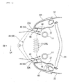
- arrows FR, UP, and LH indicate front, upper, and left sides of the vehicle, respectively.
- FIG. 1 shows a motorcycle 1 having a structure according to the embodiment of the present invention.
- a vehicle body frame F of this motorcycle 1 includes: a head pipe 12 steerably supporting front forks 11 rotationally supporting a front wheel WF; paired left and right main frames 13 and 13 extending downwardly rearward from the head pipe 12; paired left and right pivot plates 14 and 14 extending downward from rear portions of the main frames 13 and 13, respectively; and paired left and right seat rails 15 and 15 extending upwardly rearward and joined to the rear portions of the main frames 13 and 13, respectively.
- a handlebar 16 is fixed to upper portions of the front forks 11, and a fuel tank 17 is disposed above the main frames 13 and 13.
- a front seat 18 on which a driver sits is disposed behind the fuel tank 17 above the seat rails 15 and 15.
- a rear seat 19 on which a passenger sits is disposed behind the front seat 18.
- the rear seat 19 is attached in a detachably attachable manner to an upper portion of a rear cowl 20 which is supported on upper portions of the seat rails 15 and 15.
- a parallel multi-cylinder engine 21 is hung on the main frames 13 and 13.
- Reference numeral 22 in Fig. 1 represents a set of exhaust pipes connected to the engine 21.
- the exhaust pipes 22 curve downward from a front portion of the engine 21 and then extend rearward.
- a radiator 23 of a substantially rectangular shape with its longitudinal direction oriented in the vehicle width direction.
- the radiator 23 faces the front so that travelling wind can be introduced therein from the front.
- reference numeral G1 represents the center of gravity of the motorcycle 1.
- the center of gravity G1 is set at a position within the outline of the engine 21 substantially at the center in the vehicle top-bottom and front-rear directions.
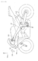
- a front end portion of a swingarm 24 is supported swingably on middle portions, in the top-bottom direction, of the pivot plates 14 and 14 through a pivot shaft 25.
- An axle 26 of a rear wheel WR is supported rotatably on a rear end portion of the swingarm 24.
- a rear fender 27 is disposed above the rear wheel WR with a certain space therebetween. The rear fender 27 extends rearward from below the seat rails 15 and 15.
- the upper side of the front wheel WF is covered with a front fender 30.
- the front fender 30 is supported on the front forks 11 and 11.
- the front side of the head pipe 12 is covered with a front cowl 31.
- Both lateral sides of a front part of the vehicle body are covered with paired left and right side cowls 32 and 32 which extend rearward continuously from lateral portions of the front cowl 31, respectively.
- a V-shaped cut is formed in an upper portion of the front cowl 31, and a screen 33 is disposed on this cut.
- the screen 33 extends obliquely upward and rearward.
- the lower side and lower lateral sides of the engine 21 are covered with an under cowl 60.
- the under cowl 60 extends in the vehicle front-rear direction.
- the front end of the under cowl 60 is continuous with the lower ends of the side cowls 32 and 32.
- Paired left and right wind exhaust openings 61 and 61 are formed in a front portion of the under cowl 60, through which travelling wind having flowed along lower portions of the side cowls 32 and 32 is exhausted outward in the vehicle width direction.
- the under cowl 60 covers also the lower side of each exhaust pipe 22.
- a heat exhaust opening 62 through which to expose part of the exhaust pipe 22 is formed in the under cowl 60 between a middle portion and a rear portion thereof in the front-rear direction.
- left and right side mirrors 34 and 34 are attached to opposite sides of the front cowl 31 having the screen 33 in between, respectively.
- Paired left and right headlight lenses 35 and 35 are provided buried below the side mirrors 34 and 34, respectively.
- the headlight lenses 35 and 35 are provided in such a fashion as to form lateral portions of the front cowl 31. As shown in Fig. 1 , the headlight lenses 35 and 35 extend obliquely upward and rearward.
- Reference numerals R and R in Fig. 2 represent ridge lines present on the front cowl 31 between the upper edges of the headlight lenses 35 and 35 and the edges of the V-shaped cut in the upper portion of the front cowl 31, respectively, and front lateral portions of the front cowl 31 are in an angular shape jutting upwardly frontward.
- the ridge lines R and R extend obliquely rearward.
- Such a shape of the front cowl 31 improves the effect of deflection of travelling wind and thereby makes it possible to produce turbulence. Accordingly, the steerability can be enhanced.
- reference numeral H in Fig. 2 represents a horn, and the horn H is housed behind the front cowl 31.
- the side cowls 32 and 32 cover the lateral sides of the vehicle continuously from the lateral portions (the rear edges of the headlight lenses 35 and 35) of the front cowl 31.
- the upper edges of the side cowls 32 and 32 extend rearward from below the handlebar 16 along the main frames 13 and 13, while the lower edges of the side cowls 32 and 32 extend downwardly rearward along the outline of the front wheel WF.
- each of the side cowls 32 and 32 is formed in a substantially triangular shape in a side view.
- front portions of the side cowls 32 and 32 extend inward in the vehicle width direction such that the front portions of the side cowls 32 and 32 cover both lateral portions of the radiator 23 from the front and lateral sides.
- Front edges 32A and 32A of the side cowls 32 and 32 extend in such a way as to curve inward in the vehicle width direction from an upper side to a lower side thereof in a front view.
- the side cowls 32 and 32 cover the both lateral portions of the radiator 23 entirely in the top-bottom direction.
- wind exhaust ports 36 and 36 are formed respectively in the side cowls 32 and 32 in the form of a cutout.
- the wind exhaust ports 36 and 36 extend obliquely upward and frontward from the rear ends of the side cowls 32 and 32, respectively.
- a part of travelling wind flowing through the radiator 23 between the side cowls 32 and 32 is exhausted outward in the vehicle width direction.
- paired left and right inner cowls 37 and 37 are disposed on the inner side of the side cowls 32 and 32, respectively.
- the inner cowls 37 and 37 straddle spaces between the lateral portions of the radiator 23 and the front edges 32A and 32A of the side cowls 32 and 32, respectively, to form paths to guide travelling wind to the radiator 23.
- the inner cowls 37 and 37 extend in the top-bottom direction in a front view behind the front edge portions 32A and 32A of the side cowls 32 and 32 and are attached and fastened to the side cowls 32 and 32 at appropriate spots with bolts.
- a spoiler member 38 is provided between upper portions of the inner cowls 37 and 37 below the front cowl 31.
- this spoiler member 38 is formed by integrally including a spoiler main portion 39 and left and right attachment plate portions 40 and 40.
- the spoiler main portion 39 extends in the vehicle width direction so as to prevent the introduction of travelling wind to the front cowl 31 side and thus to reduce lift force.
- the attachment plate portions 40 and 40 bend downward from both lateral sides of the spoiler main portion 39, overlap the inner surfaces of the inner cowls 37 and 37, and are fixed to the inner cowls 37 and 37, respectively.
- a recess 42 is formed which sinks outward in the vehicle width direction to house the head of a screw 41.
- the spoiler member 38 is fixed to the inner cowl 37 by screwing the screw 41 into the inner cowl 37.
- multiple through-holes 39A ... arranged in the vehicle width direction are formed in the spoiler main portion 39. These through-holes 39A ... are formed so that the sound generated by the horn H located above the spoiler member 38 can be outputted easily to the outside.
- left and right inhibitor portions 44 and 44 On the spoiler member 38 are formed paired left and right inhibitor portions 44 and 44 having inhibitor surfaces 43 and 43 extending inward in the vehicle width direction from the left and right attachment plate portions 40 and 40, respectively.
- the inhibitor portions 44 and 44 are formed integrally with the spoiler member 38.
- the inhibitor surfaces 43 and 43 are surfaces extending inward in the vehicle width direction from the inner surfaces, in the vehicle width direction, of the inner cowls 37 and 37 in such a way as to hit the inner surfaces, in the vehicle width direction, of the inner cowls 37 and 37 at positions upward of the center of gravity G1 of the vehicle and rearward of the front edges 32A and 32A of the side cowls 32 and 32, respectively.
- the inhibitor surfaces 43 and 43 are surfaces formed discontinuously from the design surfaces of the side cowls 32 and 32. Note that the design surfaces of the side cowls 32 and 32 refer to the lateral and front portions of the side cowls 32 and 32 that are exposed as the exterior.
- the inhibitor surfaces 43 and 43 cause travelling wind to flow to the outside of the side cowls 32 and 32.
- the inhibitor surfaces 43 and 43 respectively include: first surfaces 45 and 45 facing frontward obliquely outwardly in the vehicle width direction as shown in Fig. 6 ; second surfaces 46 and 46 located behind and below the first surfaces 45 and 45 and facing frontward as shown in Figs. 3 to 5 ; and stepped portions 47 and 47 formed between the first surfaces 45 and 45 and the second surfaces 46 and 46.
- the stepped portions 47 and 47 extend in the front-rear direction.
- lateral surface portions 48 and 48 which bend and extend rearward therefrom.
- the portions at which the stepped portions 47 and 47, the lateral surface portions 48 and 48, and the first surfaces 45 and 45 intersect each other form bow-shaped corner portions 49 and 49, respectively, each of which is oriented frontward and downward obliquely inwardly in the vehicle width direction when the vehicle is in an upright position.
- These bow-shaped corner portions 49 and 49 are oriented to the travelling direction during cornering.
- the spoiler main portion 39 of the spoiler member 38 has a downwardly stepped portion 50 which extends downward from a position rearward of the front edge of the front cowl 31, and then extends rearward.
- both lateral end portions of the downwardly stepped portion 50 extend to the vicinities of the inner surfaces of the side cowls 32 and 32, respectively.
- the surface of the downwardly stepped portion 50 faces frontward.
- the rear upper edge of the under cowl 60 is inclined to obliquely downward and rearward from the front.
- a rib 63 which bends and extends inward in the vehicle width direction. Note that while Figs. 8 and 9 show only the rib 63 formed at the rear upper edge of the under cowl 60 on the left side, the same rib is formed at the rear upper edge of the under cowl 60 on the right side.
- FIGS. 10 , 11 , and 12 show a storage box 70 which is designed to be opened through the rear seat 19 and made of a resin material.
- the storage box 70 is supported on the seat rails 15 and 15 and covered with the rear cowl 20 which is unillustrated in the drawings.
- the storage box 70 is formed by a bottom portion 71 and peripheral wall portions 74 rising from both lateral portions of the bottom portion 71.
- the bottom portion 71 and the peripheral wall portions 74 are separate members.
- the bottom portion 71 of the storage box 70 is inclined obliquely upward and rearward along the seat rails 15 and 15.
- An unillustrated cross member is laid between the seat rails 15 and 15.
- boss portions 72 In the bottom portion 71 of the storage box 70, there are formed multiple boss portions 72 ... to insert bolts for fastening the bottom portion 71 to the cross member.
- a hook 73 protruding upward is formed integrally with a rear portion of the storage box 70.
- the hook 73 has such a shape that the hook 73 is linked integrally to a rear portion of the rear boss portion 72 and protrudes at an inclination from a direction perpendicular to the surface of the bottom portion 71 with its tip side being bent.
- the hook 73 is used to hook a rope-shaped member of rubber or the like. Since the inner side of the bent portion of the hook 73 is in an arc shape, a rope-shaped member can be easily hooked thereon.
- the bottom portion 71 of the storage box 70 is formed by molding.
- reference numeral V indicates a straight line representing the moving direction of a movable die for molding the bottom portion 71.
- the hook 73 has a portion overhanging with respect to the straight line V (the region indicated by reference numeral W shown in the drawing). For this reason, the hook 73 is molded with a die formed of a movable die, a fixed die, and additionally a slide die.
- reference numeral S represents the moving direction of this slide die.
- the motorcycle 1 includes the inhibitor portions 44 and 44 having the inhibitor surfaces 43 and 43 which extend inward in the vehicle width direction from the inner surfaces, in the vehicle width direction, of the inner cowls 37 and 37 in such a way as to be discontinuous from the design surfaces of the side cowls 32 and 32 and to hit the inner surfaces, in the vehicle width direction, of the inner cowls 37 and 37 at positions upward of the center of gravity G1 of the vehicle and rearward of the front edges 32A and 32A of the side cowls 32 and 32.
- the inhibitor surfaces 43 and 43 can cause travelling wind to flow to the outside of the side cowls 32 and 32 as much as possible as illustrated by travelling wind W1 in Fig. 6 , while suppressing the influence on the design of the side cowls 32 and 32.
- the inhibitor surfaces 43 and 43 have the first surfaces 45 and 45 facing frontward obliquely outwardly in the vehicle width direction.
- the inhibitor surfaces 43 and 43 further have the second surfaces 46 and 46 located behind the first surfaces 45 and 45 and facing frontward, and the stepped portions 47 and 47 formed between the first surfaces 45 and 45 and the second surfaces 46 and 46.
- providing the stepped portions 47 and 47 facilitates the deflection of travelling wind. This makes it easier to lean the vehicle. Accordingly, the handling performance can be improved.
- the second surfaces 46 and 46 are located below the first surfaces 45 and 45, and the stepped portions 47 and 47 extend in the front-rear direction.
- the lateral surface portions 48 and 48 which bend and extend rearward therefrom. The portions at which the stepped portions 47 and 47, the lateral surface portions 48 and 48, and the first surfaces 45 and 45 intersect each other form the bow-shaped corner portions 49 and 49 which are oriented to the travelling direction during cornering.
- the motorcycle 1 advances with the bow-shaped corner portions 49 and 49 cutting through travelling wind which sticks to the inner cowls 37 and 37.
- motorcycle travels by leaning the vehicle body rightward while moving forward in an obliquely right direction.
- the left inner cowl receives travelling wind from the obliquely right direction (travelling direction), and also receives a resistance of air which is pushed away by the leaning of the vehicle body.
- the bow-shaped corner portions 49 and 49 can reduce the resistance acting on the handling.
- the inhibitor portions 44 and 44 are provided to the spoiler member 38 extending between upper portions of the left and right inner cowls 37 and 37, and the front cowl 31 is provided between upper portions of the left and right side cowls 32 and 32.
- the spoiler member 38 has the downwardly stepped portion 50 located below the front cowl 31 and extending downward from a position rearward of the front edge of the front cowl 31 and then extending rearward.
- the downwardly stepped portion 50 drooping below the front cowl 31 can facilitate the deflection of travelling wind as illustrated by the travelling wind W2 in Fig. 7 . This makes it easier to lean the vehicle. Accordingly, the handling performance can be improved.
- the present invention is not limited to this embodiment.
- the inhibitor portions 44 and 44 and the spoiler member 38 are integral with each other in the description of the above embodiment, the inhibitor portions 44 and 44 and the inner cowls 37 and 37 may be molded integrally with each other, or may be attached as separated bodies.
- the present invention is directed to provide a cowl structure of a saddle-ride type vehicle which can reduce travelling wind flowing through a radiator above the center of gravity of the vehicle, without deteriorating the design freedom.
- a motorcycle includes: paired left and right side cowls 32 covering both lateral sides of a front part of the vehicle, respectively; a radiator 23 having left and right lateral portions thereof covered with the side cowls 32, respectively, and disposed facing frontward; and paired left and right inner cowls disposed between the radiator 23 and the side cowls 32 in such a way as to straddle spaces between the lateral portions of the radiator 23 and front edges of the side cowls 32, respectively.
- the motorcycle includes inhibitor portions 44 having inhibitor surfaces 43 extending inward in a vehicle width direction from inner surfaces, in the vehicle width direction, of the inner cowls in such a way as to be discontinuous from design surfaces of the side cowls 32 and to hit the inner surfaces, in the vehicle width direction, of the inner cowls at positions upward of a center of gravity G1 of the vehicle and rearward of the front edges of the side cowls 32, respectively.
Description
- The present invention relates to a saddle-ride type vehicle having a cowl structure.
- A saddle-ride type vehicle according to the preamble of claim 1 is known from
US 2006/048991 A1 . - Japanese Patent Document No.
JP-A-4358011 Figs. 13 and14 show a conventional motorcycle having the above structure, andreference numerals - In such a motorcycle, when reference numeral G2 in
Figs. 13 and14 is set as the center of gravity of the motorcycle, a part (134) of travelling wind flowing through theradiator 132 flows above the center of gravity G2 of the vehicle. In addition, since travelling wind cannot freely flow through theradiator 132, the motorcycle is subjected to a resistance by the travelling wind. For this reason, the motorcycle is subjected to a moment (135) in a direction to lift a front part of the vehicle by the resistance of the travelling wind flowing above the center of gravity G2. This in turn decreases the load distributed to the front wheel. - It is desired to suppress such a decrease in the load distributed to the front wheel in some cases depending on the type of vehicle. To do so, it is possible, for example, to extend the left and right side cowls inward in the vehicle width direction from an opening formed by the front edges thereof, so as to make it difficult for the travelling wind to flow through the radiator above the center of gravity. Such a method, however, has a problem of influencing the design of the side cowls.
- The present invention has been made in view of the above circumstance, and an object thereof is to provide a saddle-ride type vehicle having a cowl structure and a radiator disposed between side cowls of said cowl structure, in which the cowl structure can reduce travelling wind flowing through the radiator above the center of gravity of the vehicle, without deteriorating the design freedom.
- For the purpose of solving the above-mentioned problem, a first aspect of the present invention provides a saddle-ride type vehicle having a cowl structure, including: paired left and right side cowls (32) covering both lateral sides of a front part of the vehicle, respectively; a radiator (23) having left and right lateral portions thereof covered with the side cowls (32), respectively, and disposed facing frontward; and paired left and right inner cowls (37) disposed between the radiator (23) and the side cowls (32) in such a way as to straddle spaces between the lateral portions of the radiator (23) and front edges of the side cowls (32), respectively. The cowl structure includes inhibitor portions (44) having inhibitor surfaces (43) extending inward in a vehicle width direction from inner surfaces, in the vehicle width direction, of the inner cowls in such a way as to be discontinuous from design surfaces of the side cowls (32) and to hit the inner surfaces, in the vehicle width direction, of the inner cowls (37) at positions upward of a center of gravity (G1) of the vehicle and rearward of the front edges of the side cowls (32), respectively.
- According to a second aspect of the present invention, in the saddle-ride type vehicle according to the first aspect of the present invention, each of the inhibitor surfaces (43) has a first surface (45) facing frontward obliquely outwardly in the vehicle width direction.
- According to a third aspect of the present invention, in the saddle-ride type vehicle according to the second aspect of the present invention, each of the inhibitor surfaces (43) further has a second surface (46) located behind the first surface (45) and facing frontward, and a stepped portion (47) formed between the first surface (45) and the second surface (46).
- According to a fourth aspect of the present invention, in the saddle-ride type vehicle according to the third aspect of the present invention, the saddle-ride type vehicle is a motorcycle; the second surface (46) is located below the first surface (45); the stepped portion (47) extends in a front-rear direction; on an inner edge of the first surface (45) in the vehicle width direction, a lateral surface portion (48) is provided which bends and extends rearward therefrom; and a portion at which the stepped portion (47), the lateral surface portion (48), and the first surface (45) intersect each other forms a bow-shaped corner portion (49) which is oriented to a travelling direction during cornering.
- According to a fifth aspect of the present invention, in the saddle-ride type vehicle according to the third aspect of the present invention, each of the inhibitor portions (44) is provided to a spoiler member (38) extending between upper portions of the left and right inner cowls (37); a front cowl (31) is provided between upper portions of the left and right side cowls (32); and the spoiler member (38) has a downwardly stepped portion (50) located below the front cowl (31) and extending downward from a position rearward of a front edge of the front cowl (31) and then extending rearward.
- According to the first aspect of the present invention, the inhibitor surfaces can cause travelling wind to flow to the outside of the side cowls as much as possible, while suppressing the influence on the design of the side cowls. This reduces travelling wind flowing through the radiator above the center of gravity. Accordingly, the decrease in the load distributed to the front wheel can be suppressed.
- According to the second aspect of the present invention, the inhibitor surfaces face frontward obliquely outwardly in the vehicle width direction. Accordingly, the flow of travelling wind can be directed to the outside of the side cowls efficiently.
- According to the third aspect of the present invention, the stepped portion is provided to each inhibitor surface. Thus, the deflection of travelling wind can be facilitated. This makes it easier to lean the vehicle. Accordingly, the handling performance can be improved.
- According to the fourth aspect of the present invention, the bow-shaped corner portions which are oriented to the travelling direction during cornering are provided. Thus, during cornering, the saddle-ride type vehicle advances with the bow-shaped corner portions cutting through travelling wind which sticks to the inner cowls. This makes it easier to lean the vehicle body, that is, reduces the resistance acting on the handling. Accordingly, the steerability can be enhanced. To be specific, during cornering to the right, for example, motorcycle travels by leaning the vehicle body rightward while moving forward in an obliquely right direction. During this action, the left inner cowl receives travelling wind from the obliquely right direction (travelling direction), and also receives a resistance of air which is pushed away by the leaning of the vehicle body. In this respect, the bow-shaped corner portions can reduce the resistance acting on the handling.
- According to the fifth aspect of the present invention, the downwardly stepped portion drooping below the front cowl can facilitate the deflection of travelling wind. This makes it easier to lean the vehicle. Accordingly, the handling performance can be improved.
-
- Fig. 1
- is a left-side view of a motorcycle having a structure according to an embodiment of the present invention.
- Fig. 2
- is a front view of the motorcycle.
- Fig. 3
- is an enlarged view of a main part in
Fig. 2 . - Fig. 4
- is a perspective view of a front part of the motorcycle as seen from the front in an obliquely upward direction.
- Fig. 5
- is an enlarged view of a main part in
Fig. 4 . - Fig. 6
- is a cross-sectional view taken along the A-A line in
Fig. 3 . - Fig. 7
- is a cross-sectional view taken along the B-B line in
Fig. 2 . - Fig. 8
- is a perspective view showing a rear portion of an under cowl of the motorcycle.
- Fig. 9
- is a cross-sectional view taken along the C-C line in
Fig. 1 . - Fig. 10
- is a perspective view of a rear part of the motorcycle with a rear seat of the motorcycle being detached.
- Fig. 11
- is an enlarged view of a main part in
Fig. 10 . - Fig. 12
- is a vertical cross-sectional view of a storage box disposed below the rear seat.
- Fig. 13
- is a left-side view of a conventional motorcycle.
- Fig. 14
- is a front view of the conventional motorcycle.
- Hereinbelow, an embodiment of the present invention will be described based on the drawings. Note that in the drawings used below, arrows FR, UP, and LH indicate front, upper, and left sides of the vehicle, respectively.
-
Fig. 1 shows a motorcycle 1 having a structure according to the embodiment of the present invention. A vehicle body frame F of this motorcycle 1 includes: ahead pipe 12 steerably supportingfront forks 11 rotationally supporting a front wheel WF; paired left and rightmain frames head pipe 12; paired left andright pivot plates main frames main frames - A
handlebar 16 is fixed to upper portions of thefront forks 11, and afuel tank 17 is disposed above themain frames front seat 18 on which a driver sits is disposed behind thefuel tank 17 above the seat rails 15 and 15. Arear seat 19 on which a passenger sits is disposed behind thefront seat 18. Therear seat 19 is attached in a detachably attachable manner to an upper portion of arear cowl 20 which is supported on upper portions of the seat rails 15 and 15. - A
parallel multi-cylinder engine 21 is hung on themain frames Reference numeral 22 inFig. 1 represents a set of exhaust pipes connected to theengine 21. Theexhaust pipes 22 curve downward from a front portion of theengine 21 and then extend rearward. Referring also toFig. 2 , in front of theengine 21 is disposed aradiator 23 of a substantially rectangular shape with its longitudinal direction oriented in the vehicle width direction. Theradiator 23 faces the front so that travelling wind can be introduced therein from the front. - The
radiator 23 is supported by unillustrated brackets fixed to themain frames engine 21 substantially at the center in the vehicle top-bottom and front-rear directions. - A front end portion of a
swingarm 24 is supported swingably on middle portions, in the top-bottom direction, of thepivot plates pivot shaft 25. Anaxle 26 of a rear wheel WR is supported rotatably on a rear end portion of theswingarm 24. Arear fender 27 is disposed above the rear wheel WR with a certain space therebetween. Therear fender 27 extends rearward from below the seat rails 15 and 15. - The upper side of the front wheel WF is covered with a
front fender 30. Thefront fender 30 is supported on thefront forks head pipe 12 is covered with afront cowl 31. Both lateral sides of a front part of the vehicle body are covered with paired left and right side cowls 32 and 32 which extend rearward continuously from lateral portions of thefront cowl 31, respectively. As shown inFig. 2 , a V-shaped cut is formed in an upper portion of thefront cowl 31, and ascreen 33 is disposed on this cut. Thescreen 33 extends obliquely upward and rearward. - Moreover, the lower side and lower lateral sides of the
engine 21 are covered with an undercowl 60. The undercowl 60 extends in the vehicle front-rear direction. The front end of theunder cowl 60 is continuous with the lower ends of the side cowls 32 and 32. Paired left and rightwind exhaust openings under cowl 60, through which travelling wind having flowed along lower portions of the side cowls 32 and 32 is exhausted outward in the vehicle width direction. The undercowl 60 covers also the lower side of eachexhaust pipe 22. Aheat exhaust opening 62 through which to expose part of theexhaust pipe 22 is formed in the undercowl 60 between a middle portion and a rear portion thereof in the front-rear direction. - Referring to
Fig. 2 , left and right side mirrors 34 and 34 are attached to opposite sides of thefront cowl 31 having thescreen 33 in between, respectively. Paired left andright headlight lenses headlight lenses front cowl 31. As shown inFig. 1 , theheadlight lenses - Reference numerals R and R in
Fig. 2 represent ridge lines present on thefront cowl 31 between the upper edges of theheadlight lenses front cowl 31, respectively, and front lateral portions of thefront cowl 31 are in an angular shape jutting upwardly frontward. In thefront cowl 31, the ridge lines R and R extend obliquely rearward. Such a shape of thefront cowl 31 improves the effect of deflection of travelling wind and thereby makes it possible to produce turbulence. Accordingly, the steerability can be enhanced. Meanwhile, reference numeral H inFig. 2 represents a horn, and the horn H is housed behind thefront cowl 31. - The side cowls 32 and 32 cover the lateral sides of the vehicle continuously from the lateral portions (the rear edges of the
headlight lenses 35 and 35) of thefront cowl 31. The upper edges of the side cowls 32 and 32 extend rearward from below thehandlebar 16 along themain frames - As shown in
Figs. 2 ,3 , and4 , front portions of the side cowls 32 and 32 extend inward in the vehicle width direction such that the front portions of the side cowls 32 and 32 cover both lateral portions of theradiator 23 from the front and lateral sides. Front edges 32A and 32A of the side cowls 32 and 32 extend in such a way as to curve inward in the vehicle width direction from an upper side to a lower side thereof in a front view. The side cowls 32 and 32 cover the both lateral portions of theradiator 23 entirely in the top-bottom direction. - Referring to
Fig. 1 ,wind exhaust ports wind exhaust ports wind exhaust ports radiator 23 between the side cowls 32 and 32 is exhausted outward in the vehicle width direction. - Referring to
Figs. 4 ,5 , and6 , paired left and rightinner cowls inner cowls radiator 23 and thefront edges radiator 23. Theinner cowls front edge portions - Referring also to
Fig. 3 , aspoiler member 38 is provided between upper portions of theinner cowls front cowl 31. Referring also toFig. 7 , thisspoiler member 38 is formed by integrally including a spoilermain portion 39 and left and rightattachment plate portions main portion 39 extends in the vehicle width direction so as to prevent the introduction of travelling wind to thefront cowl 31 side and thus to reduce lift force. As shown inFig. 4 , theattachment plate portions main portion 39, overlap the inner surfaces of theinner cowls inner cowls - In each of the
attachment plates recess 42 is formed which sinks outward in the vehicle width direction to house the head of ascrew 41. Thespoiler member 38 is fixed to theinner cowl 37 by screwing thescrew 41 into theinner cowl 37. Moreover, multiple through-holes 39A ... arranged in the vehicle width direction are formed in the spoilermain portion 39. These through-holes 39A ... are formed so that the sound generated by the horn H located above thespoiler member 38 can be outputted easily to the outside. - On the
spoiler member 38 are formed paired left andright inhibitor portions attachment plate portions inhibitor portions spoiler member 38. - Referring to
Figs. 2 ,3 , and6 , the inhibitor surfaces 43 and 43 are surfaces extending inward in the vehicle width direction from the inner surfaces, in the vehicle width direction, of theinner cowls inner cowls front edges - Extending inward in the vehicle width direction from the inner surfaces, in the vehicle width direction, of the
inner cowls Fig. 6 ; second surfaces 46 and 46 located behind and below thefirst surfaces Figs. 3 to 5 ; and steppedportions first surfaces second surfaces portions first surfaces lateral surface portions - Here, the portions at which the stepped
portions lateral surface portions first surfaces corner portions corner portions - On the other hand, referring to
Fig. 7 , the spoilermain portion 39 of thespoiler member 38 has a downwardly steppedportion 50 which extends downward from a position rearward of the front edge of thefront cowl 31, and then extends rearward. As shown inFig. 3 , both lateral end portions of the downwardly steppedportion 50 extend to the vicinities of the inner surfaces of the side cowls 32 and 32, respectively. The surface of the downwardly steppedportion 50 faces frontward. - Meanwhile, in the motorcycle 1, as shown in
Fig. 8 , the rear upper edge of theunder cowl 60 is inclined to obliquely downward and rearward from the front. Moreover, as shown inFig. 9 , at the rear upper edge of theunder cowl 60, there is formed arib 63 which bends and extends inward in the vehicle width direction. Note that whileFigs. 8 and9 show only therib 63 formed at the rear upper edge of theunder cowl 60 on the left side, the same rib is formed at the rear upper edge of theunder cowl 60 on the right side. - Referring next to
Figs. 10 ,11 , and12 , the drawings show astorage box 70 which is designed to be opened through therear seat 19 and made of a resin material. Thestorage box 70 is supported on the seat rails 15 and 15 and covered with therear cowl 20 which is unillustrated in the drawings. Thestorage box 70 is formed by abottom portion 71 andperipheral wall portions 74 rising from both lateral portions of thebottom portion 71. Thebottom portion 71 and theperipheral wall portions 74 are separate members. - The
bottom portion 71 of thestorage box 70 is inclined obliquely upward and rearward along the seat rails 15 and 15. An unillustrated cross member is laid between the seat rails 15 and 15. In thebottom portion 71 of thestorage box 70, there are formedmultiple boss portions 72 ... to insert bolts for fastening thebottom portion 71 to the cross member. - A
hook 73 protruding upward is formed integrally with a rear portion of thestorage box 70. As shown inFig. 11 , thehook 73 has such a shape that thehook 73 is linked integrally to a rear portion of therear boss portion 72 and protrudes at an inclination from a direction perpendicular to the surface of thebottom portion 71 with its tip side being bent. Thehook 73 is used to hook a rope-shaped member of rubber or the like. Since the inner side of the bent portion of thehook 73 is in an arc shape, a rope-shaped member can be easily hooked thereon. - The
bottom portion 71 of thestorage box 70 is formed by molding. InFig. 12 , reference numeral V indicates a straight line representing the moving direction of a movable die for molding thebottom portion 71. As is obvious from this straight line V, thehook 73 has a portion overhanging with respect to the straight line V (the region indicated by reference numeral W shown in the drawing). For this reason, thehook 73 is molded with a die formed of a movable die, a fixed die, and additionally a slide die. In the drawing, reference numeral S represents the moving direction of this slide die. - As described above, the motorcycle 1 includes the
inhibitor portions inner cowls inner cowls front edges - By such a structure, the inhibitor surfaces 43 and 43 can cause travelling wind to flow to the outside of the side cowls 32 and 32 as much as possible as illustrated by travelling wind W1 in
Fig. 6 , while suppressing the influence on the design of the side cowls 32 and 32. This reduces travelling wind flowing through theradiator 23 above the center of gravity G1. Accordingly, the decrease in the load distributed to the front wheel can be suppressed. - Moreover, in the motorcycle 1, the inhibitor surfaces 43 and 43 have the
first surfaces - Further, the inhibitor surfaces 43 and 43 further have the
second surfaces first surfaces portions first surfaces second surfaces portions - In addition, the
second surfaces first surfaces portions first surfaces lateral surface portions portions lateral surface portions first surfaces corner portions - In such a configuration, by providing the bow-shaped
corner portions corner portions inner cowls corner portions - Further, in the motorcycle 1, the
inhibitor portions spoiler member 38 extending between upper portions of the left and rightinner cowls front cowl 31 is provided between upper portions of the left and right side cowls 32 and 32. Moreover, thespoiler member 38 has the downwardly steppedportion 50 located below thefront cowl 31 and extending downward from a position rearward of the front edge of thefront cowl 31 and then extending rearward. In such a configuration, the downwardly steppedportion 50 drooping below thefront cowl 31 can facilitate the deflection of travelling wind as illustrated by the travelling wind W2 inFig. 7 . This makes it easier to lean the vehicle. Accordingly, the handling performance can be improved. - While an embodiment of the present invention has been described above, the present invention is not limited to this embodiment. For example, while the
inhibitor portions spoiler member 38 are integral with each other in the description of the above embodiment, theinhibitor portions inner cowls - The present invention is directed to provide a cowl structure of a saddle-ride type vehicle which can reduce travelling wind flowing through a radiator above the center of gravity of the vehicle, without deteriorating the design freedom.
- A motorcycle includes: paired left and right side cowls 32 covering both lateral sides of a front part of the vehicle, respectively; a
radiator 23 having left and right lateral portions thereof covered with the side cowls 32, respectively, and disposed facing frontward; and paired left and right inner cowls disposed between theradiator 23 and the side cowls 32 in such a way as to straddle spaces between the lateral portions of theradiator 23 and front edges of the side cowls 32, respectively. In addition, the motorcycle includesinhibitor portions 44 having inhibitor surfaces 43 extending inward in a vehicle width direction from inner surfaces, in the vehicle width direction, of the inner cowls in such a way as to be discontinuous from design surfaces of the side cowls 32 and to hit the inner surfaces, in the vehicle width direction, of the inner cowls at positions upward of a center of gravity G1 of the vehicle and rearward of the front edges of the side cowls 32, respectively.
Claims (5)
- A saddle-ride type vehicle having a cowl structure, including:paired left and right side cowls (32) covering both lateral sides of a front part of the vehicle, respectively;a radiator (23) having left and right lateral portions thereof covered with the side cowls (32), respectively, and disposed facing frontward; andpaired left and right inner cowls (37) disposed between the radiator (23) and the side cowls (32) in such a way as to straddle spaces between the lateral portions of the radiator (23) and front edges of the side cowls (32), respectively,characterized in that the cowl structure comprisesinhibitor portions (44) having inhibitor surfaces (43) extending inward in a vehicle width direction from inner surfaces, in the vehicle width direction, of the inner cowls in such a way as to be discontinuous from design surfaces of the side cowls (32) and to hit the inner surfaces, in the vehicle width direction, of the inner cowls (37) at positions upward of a center of gravity (G1) of the vehicle and rearward of the front edges of the side cowls (32), respectively.
- The saddle-ride type vehicle according to claim 1, wherein each of the inhibitor surfaces (43) has a first surface (45) facing frontward obliquely outwardly in the vehicle width direction.
- The saddle-ride type vehicle according to claim 2, wherein each of the inhibitor surfaces (43) further has a second surface (46) located behind the first surface (45) and facing frontward, and a stepped portion (47) formed between the first surface (45) and the second surface (46).
- The saddle-ride type vehicle according to claim 3, wherein the saddle-ride type vehicle is a motorcycle,
the second surface (46) is located below the first surface (45),
the stepped portion (47) extends in a front-rear direction,
on an inner edge of the first surface (45) in the vehicle width direction, a lateral surface portion (48) is provided which bends and extends rearward therefrom, and
a portion at which the stepped portion (47), the lateral surface portion (48), and the first surface (45) intersect each other forms a bow-shaped corner portion (49) which is oriented to a travelling direction during cornering. - The saddle-ride type vehicle according to claim 3, wherein each of the inhibitor portions (44) is provided to a spoiler member (38) extending between upper portions of the left and right inner cowls (37),
a front cowl (31) is provided between upper portions of the left and right side cowls (32), and
the spoiler member (38) has a downwardly stepped portion (50) located below the front cowl (31) and extending downward from a position rearward of a front edge of the front cowl (31) and then extending rearward.
Applications Claiming Priority (1)
| Application Number | Priority Date | Filing Date | Title |
|---|---|---|---|
| JP2011151000A JP5685155B2 (en) | 2011-07-07 | 2011-07-07 | Cowling structure of saddle riding type vehicle |
Publications (2)
| Publication Number | Publication Date |
|---|---|
| EP2543581A1 EP2543581A1 (en) | 2013-01-09 |
| EP2543581B1 true EP2543581B1 (en) | 2013-10-23 |
Family
ID=46319604
Family Applications (1)
| Application Number | Title | Priority Date | Filing Date |
|---|---|---|---|
| EP12172396.9A Not-in-force EP2543581B1 (en) | 2011-07-07 | 2012-06-18 | Cowl structure of saddle-ride type vehicle |
Country Status (2)
| Country | Link |
|---|---|
| EP (1) | EP2543581B1 (en) |
| JP (1) | JP5685155B2 (en) |
Families Citing this family (4)
| Publication number | Priority date | Publication date | Assignee | Title |
|---|---|---|---|---|
| EP2712795B1 (en) * | 2012-09-28 | 2015-08-05 | Yamaha Motor Co., Ltd. | Straddle-type vehicle |
| EP3072791B1 (en) * | 2013-11-15 | 2020-01-08 | Kawasaki Jukogyo Kabushiki Kaisha | Straddle-type vehicle |
| JP6467192B2 (en) * | 2013-11-15 | 2019-02-06 | 川崎重工業株式会社 | Saddle riding vehicle |
| JP2022044198A (en) * | 2020-09-07 | 2022-03-17 | スズキ株式会社 | Front cowl |
Family Cites Families (7)
| Publication number | Priority date | Publication date | Assignee | Title |
|---|---|---|---|---|
| JPH0694567B2 (en) | 1991-06-03 | 1994-11-24 | 石川島播磨重工業株式会社 | Raw material charging device |
| JP4358011B2 (en) * | 2004-03-26 | 2009-11-04 | 本田技研工業株式会社 | Motorcycle cowl structure |
| JP2006069404A (en) * | 2004-09-03 | 2006-03-16 | Yamaha Motor Co Ltd | Vehicle |
| JP2009107569A (en) * | 2007-10-31 | 2009-05-21 | Yamaha Motor Co Ltd | Cowl for motorcycle, and motorcycle |
| JP3154590U (en) * | 2008-09-05 | 2009-10-22 | ヤマハ発動機株式会社 | Motorcycle |
| JP5320127B2 (en) * | 2009-03-30 | 2013-10-23 | 本田技研工業株式会社 | Saddle riding |
| JP2011011570A (en) * | 2009-06-30 | 2011-01-20 | Kawasaki Heavy Ind Ltd | Front cowling for motorcycle |
-
2011
- 2011-07-07 JP JP2011151000A patent/JP5685155B2/en active Active
-
2012
- 2012-06-18 EP EP12172396.9A patent/EP2543581B1/en not_active Not-in-force
Also Published As
| Publication number | Publication date |
|---|---|
| JP5685155B2 (en) | 2015-03-18 |
| JP2013018306A (en) | 2013-01-31 |
| EP2543581A1 (en) | 2013-01-09 |
Similar Documents
| Publication | Publication Date | Title |
|---|---|---|
| US7370902B2 (en) | Cowling structure of motorcycle | |
| JP5883716B2 (en) | Wind guide structure of saddle-ride type vehicle | |
| JP5555586B2 (en) | Fairing structure for saddle-ride type vehicles | |
| EP3002190B1 (en) | Saddle-type ride vehicle | |
| JP6254511B2 (en) | Front fender for saddle-ride type vehicles | |
| US9834272B2 (en) | Saddle-ride type vehicle | |
| US10450026B2 (en) | Air guide structure of a saddle-type vehicle | |
| EP2543581B1 (en) | Cowl structure of saddle-ride type vehicle | |
| US7325853B2 (en) | Arrangement structure of upper cowl, screen, and meter for motorcycles | |
| US9714062B2 (en) | Saddle-ride-type vehicle | |
| JP5728331B2 (en) | Mudguard structure of saddle-ride type vehicle | |
| JP5604124B2 (en) | Motorcycle | |
| EP3059149B1 (en) | Front structure of straddle-type vehicle | |
| EP2644488B1 (en) | Saddle-ride type vehicle | |
| JP6099694B2 (en) | Saddle riding | |
| JP5700676B2 (en) | Exterior parts for saddle riding type vehicles | |
| JP5455509B2 (en) | Under cowl structure for saddle-ride type vehicles | |
| US7651149B2 (en) | Windshield unit for saddle-ride type vehicle | |
| JP6003477B2 (en) | Handle cover device for motorcycle | |
| JP5784434B2 (en) | Vehicle front structure | |
| EP3002188B1 (en) | Saddle-type ride vehicle | |
| US8887851B2 (en) | Saddle-ride type vehicle | |
| JP5883775B2 (en) | Wind guide structure of saddle riding type vehicle | |
| CN110300699B (en) | Saddle-ride type vehicle | |
| JP2017159755A (en) | Vehicle side cover |
Legal Events
| Date | Code | Title | Description |
|---|---|---|---|
| PUAI | Public reference made under article 153(3) epc to a published international application that has entered the european phase |
Free format text: ORIGINAL CODE: 0009012 |
|
| 17P | Request for examination filed |
Effective date: 20120618 |
|
| AK | Designated contracting states |
Kind code of ref document: A1 Designated state(s): AL AT BE BG CH CY CZ DE DK EE ES FI FR GB GR HR HU IE IS IT LI LT LU LV MC MK MT NL NO PL PT RO RS SE SI SK SM TR |
|
| AX | Request for extension of the european patent |
Extension state: BA ME |
|
| RIC1 | Information provided on ipc code assigned before grant |
Ipc: F02M 35/16 20060101ALI20130213BHEP Ipc: B62J 17/02 20060101AFI20130213BHEP |
|
| GRAP | Despatch of communication of intention to grant a patent |
Free format text: ORIGINAL CODE: EPIDOSNIGR1 |
|
| INTG | Intention to grant announced |
Effective date: 20130425 |
|
| GRAS | Grant fee paid |
Free format text: ORIGINAL CODE: EPIDOSNIGR3 |
|
| GRAA | (expected) grant |
Free format text: ORIGINAL CODE: 0009210 |
|
| AK | Designated contracting states |
Kind code of ref document: B1 Designated state(s): AL AT BE BG CH CY CZ DE DK EE ES FI FR GB GR HR HU IE IS IT LI LT LU LV MC MK MT NL NO PL PT RO RS SE SI SK SM TR |
|
| REG | Reference to a national code |
Ref country code: GB Ref legal event code: FG4D |
|
| REG | Reference to a national code |
Ref country code: CH Ref legal event code: EP |
|
| REG | Reference to a national code |
Ref country code: AT Ref legal event code: REF Ref document number: 637408 Country of ref document: AT Kind code of ref document: T Effective date: 20131115 |
|
| REG | Reference to a national code |
Ref country code: IE Ref legal event code: FG4D |
|
| REG | Reference to a national code |
Ref country code: DE Ref legal event code: R096 Ref document number: 602012000421 Country of ref document: DE Effective date: 20131224 |
|
| REG | Reference to a national code |
Ref country code: NL Ref legal event code: VDEP Effective date: 20131023 |
|
| REG | Reference to a national code |
Ref country code: AT Ref legal event code: MK05 Ref document number: 637408 Country of ref document: AT Kind code of ref document: T Effective date: 20131023 |
|
| REG | Reference to a national code |
Ref country code: LT Ref legal event code: MG4D |
|
| PG25 | Lapsed in a contracting state [announced via postgrant information from national office to epo] |
Ref country code: NL Free format text: LAPSE BECAUSE OF FAILURE TO SUBMIT A TRANSLATION OF THE DESCRIPTION OR TO PAY THE FEE WITHIN THE PRESCRIBED TIME-LIMIT Effective date: 20131023 Ref country code: SE Free format text: LAPSE BECAUSE OF FAILURE TO SUBMIT A TRANSLATION OF THE DESCRIPTION OR TO PAY THE FEE WITHIN THE PRESCRIBED TIME-LIMIT Effective date: 20131023 Ref country code: BE Free format text: LAPSE BECAUSE OF FAILURE TO SUBMIT A TRANSLATION OF THE DESCRIPTION OR TO PAY THE FEE WITHIN THE PRESCRIBED TIME-LIMIT Effective date: 20131023 Ref country code: IS Free format text: LAPSE BECAUSE OF FAILURE TO SUBMIT A TRANSLATION OF THE DESCRIPTION OR TO PAY THE FEE WITHIN THE PRESCRIBED TIME-LIMIT Effective date: 20140223 Ref country code: NO Free format text: LAPSE BECAUSE OF FAILURE TO SUBMIT A TRANSLATION OF THE DESCRIPTION OR TO PAY THE FEE WITHIN THE PRESCRIBED TIME-LIMIT Effective date: 20140123 Ref country code: FI Free format text: LAPSE BECAUSE OF FAILURE TO SUBMIT A TRANSLATION OF THE DESCRIPTION OR TO PAY THE FEE WITHIN THE PRESCRIBED TIME-LIMIT Effective date: 20131023 Ref country code: LT Free format text: LAPSE BECAUSE OF FAILURE TO SUBMIT A TRANSLATION OF THE DESCRIPTION OR TO PAY THE FEE WITHIN THE PRESCRIBED TIME-LIMIT Effective date: 20131023 Ref country code: HR Free format text: LAPSE BECAUSE OF FAILURE TO SUBMIT A TRANSLATION OF THE DESCRIPTION OR TO PAY THE FEE WITHIN THE PRESCRIBED TIME-LIMIT Effective date: 20131023 |
|
| PG25 | Lapsed in a contracting state [announced via postgrant information from national office to epo] |
Ref country code: LV Free format text: LAPSE BECAUSE OF FAILURE TO SUBMIT A TRANSLATION OF THE DESCRIPTION OR TO PAY THE FEE WITHIN THE PRESCRIBED TIME-LIMIT Effective date: 20131023 Ref country code: RS Free format text: LAPSE BECAUSE OF FAILURE TO SUBMIT A TRANSLATION OF THE DESCRIPTION OR TO PAY THE FEE WITHIN THE PRESCRIBED TIME-LIMIT Effective date: 20131023 Ref country code: ES Free format text: LAPSE BECAUSE OF FAILURE TO SUBMIT A TRANSLATION OF THE DESCRIPTION OR TO PAY THE FEE WITHIN THE PRESCRIBED TIME-LIMIT Effective date: 20131023 Ref country code: CY Free format text: LAPSE BECAUSE OF FAILURE TO SUBMIT A TRANSLATION OF THE DESCRIPTION OR TO PAY THE FEE WITHIN THE PRESCRIBED TIME-LIMIT Effective date: 20131023 Ref country code: AT Free format text: LAPSE BECAUSE OF FAILURE TO SUBMIT A TRANSLATION OF THE DESCRIPTION OR TO PAY THE FEE WITHIN THE PRESCRIBED TIME-LIMIT Effective date: 20131023 |
|
| PG25 | Lapsed in a contracting state [announced via postgrant information from national office to epo] |
Ref country code: PT Free format text: LAPSE BECAUSE OF FAILURE TO SUBMIT A TRANSLATION OF THE DESCRIPTION OR TO PAY THE FEE WITHIN THE PRESCRIBED TIME-LIMIT Effective date: 20140224 |
|
| REG | Reference to a national code |
Ref country code: DE Ref legal event code: R097 Ref document number: 602012000421 Country of ref document: DE |
|
| PG25 | Lapsed in a contracting state [announced via postgrant information from national office to epo] |
Ref country code: EE Free format text: LAPSE BECAUSE OF FAILURE TO SUBMIT A TRANSLATION OF THE DESCRIPTION OR TO PAY THE FEE WITHIN THE PRESCRIBED TIME-LIMIT Effective date: 20131023 |
|
| PG25 | Lapsed in a contracting state [announced via postgrant information from national office to epo] |
Ref country code: SK Free format text: LAPSE BECAUSE OF FAILURE TO SUBMIT A TRANSLATION OF THE DESCRIPTION OR TO PAY THE FEE WITHIN THE PRESCRIBED TIME-LIMIT Effective date: 20131023 Ref country code: PL Free format text: LAPSE BECAUSE OF FAILURE TO SUBMIT A TRANSLATION OF THE DESCRIPTION OR TO PAY THE FEE WITHIN THE PRESCRIBED TIME-LIMIT Effective date: 20131023 Ref country code: RO Free format text: LAPSE BECAUSE OF FAILURE TO SUBMIT A TRANSLATION OF THE DESCRIPTION OR TO PAY THE FEE WITHIN THE PRESCRIBED TIME-LIMIT Effective date: 20131023 Ref country code: CZ Free format text: LAPSE BECAUSE OF FAILURE TO SUBMIT A TRANSLATION OF THE DESCRIPTION OR TO PAY THE FEE WITHIN THE PRESCRIBED TIME-LIMIT Effective date: 20131023 |
|
| PLBE | No opposition filed within time limit |
Free format text: ORIGINAL CODE: 0009261 |
|
| STAA | Information on the status of an ep patent application or granted ep patent |
Free format text: STATUS: NO OPPOSITION FILED WITHIN TIME LIMIT |
|
| PG25 | Lapsed in a contracting state [announced via postgrant information from national office to epo] |
Ref country code: DK Free format text: LAPSE BECAUSE OF FAILURE TO SUBMIT A TRANSLATION OF THE DESCRIPTION OR TO PAY THE FEE WITHIN THE PRESCRIBED TIME-LIMIT Effective date: 20131023 |
|
| 26N | No opposition filed |
Effective date: 20140724 |
|
| REG | Reference to a national code |
Ref country code: DE Ref legal event code: R097 Ref document number: 602012000421 Country of ref document: DE Effective date: 20140724 |
|
| PG25 | Lapsed in a contracting state [announced via postgrant information from national office to epo] |
Ref country code: MC Free format text: LAPSE BECAUSE OF FAILURE TO SUBMIT A TRANSLATION OF THE DESCRIPTION OR TO PAY THE FEE WITHIN THE PRESCRIBED TIME-LIMIT Effective date: 20131023 Ref country code: LU Free format text: LAPSE BECAUSE OF FAILURE TO SUBMIT A TRANSLATION OF THE DESCRIPTION OR TO PAY THE FEE WITHIN THE PRESCRIBED TIME-LIMIT Effective date: 20140618 |
|
| REG | Reference to a national code |
Ref country code: DE Ref legal event code: R084 Ref document number: 602012000421 Country of ref document: DE |
|
| PG25 | Lapsed in a contracting state [announced via postgrant information from national office to epo] |
Ref country code: SI Free format text: LAPSE BECAUSE OF FAILURE TO SUBMIT A TRANSLATION OF THE DESCRIPTION OR TO PAY THE FEE WITHIN THE PRESCRIBED TIME-LIMIT Effective date: 20131023 |
|
| REG | Reference to a national code |
Ref country code: IE Ref legal event code: MM4A |
|
| REG | Reference to a national code |
Ref country code: DE Ref legal event code: R084 Ref document number: 602012000421 Country of ref document: DE Effective date: 20150210 |
|
| PG25 | Lapsed in a contracting state [announced via postgrant information from national office to epo] |
Ref country code: IE Free format text: LAPSE BECAUSE OF NON-PAYMENT OF DUE FEES Effective date: 20140618 |
|
| REG | Reference to a national code |
Ref country code: CH Ref legal event code: PL |
|
| PG25 | Lapsed in a contracting state [announced via postgrant information from national office to epo] |
Ref country code: MT Free format text: LAPSE BECAUSE OF FAILURE TO SUBMIT A TRANSLATION OF THE DESCRIPTION OR TO PAY THE FEE WITHIN THE PRESCRIBED TIME-LIMIT Effective date: 20131023 |
|
| PG25 | Lapsed in a contracting state [announced via postgrant information from national office to epo] |
Ref country code: LI Free format text: LAPSE BECAUSE OF NON-PAYMENT OF DUE FEES Effective date: 20150630 Ref country code: CH Free format text: LAPSE BECAUSE OF NON-PAYMENT OF DUE FEES Effective date: 20150630 Ref country code: SM Free format text: LAPSE BECAUSE OF FAILURE TO SUBMIT A TRANSLATION OF THE DESCRIPTION OR TO PAY THE FEE WITHIN THE PRESCRIBED TIME-LIMIT Effective date: 20131023 |
|
| REG | Reference to a national code |
Ref country code: FR Ref legal event code: PLFP Year of fee payment: 5 |
|
| PG25 | Lapsed in a contracting state [announced via postgrant information from national office to epo] |
Ref country code: GR Free format text: LAPSE BECAUSE OF FAILURE TO SUBMIT A TRANSLATION OF THE DESCRIPTION OR TO PAY THE FEE WITHIN THE PRESCRIBED TIME-LIMIT Effective date: 20140124 Ref country code: BG Free format text: LAPSE BECAUSE OF FAILURE TO SUBMIT A TRANSLATION OF THE DESCRIPTION OR TO PAY THE FEE WITHIN THE PRESCRIBED TIME-LIMIT Effective date: 20131023 |
|
| PG25 | Lapsed in a contracting state [announced via postgrant information from national office to epo] |
Ref country code: HU Free format text: LAPSE BECAUSE OF FAILURE TO SUBMIT A TRANSLATION OF THE DESCRIPTION OR TO PAY THE FEE WITHIN THE PRESCRIBED TIME-LIMIT; INVALID AB INITIO Effective date: 20120618 Ref country code: TR Free format text: LAPSE BECAUSE OF FAILURE TO SUBMIT A TRANSLATION OF THE DESCRIPTION OR TO PAY THE FEE WITHIN THE PRESCRIBED TIME-LIMIT Effective date: 20131023 |
|
| GBPC | Gb: european patent ceased through non-payment of renewal fee |
Effective date: 20160618 |
|
| REG | Reference to a national code |
Ref country code: FR Ref legal event code: PLFP Year of fee payment: 6 |
|
| PG25 | Lapsed in a contracting state [announced via postgrant information from national office to epo] |
Ref country code: GB Free format text: LAPSE BECAUSE OF NON-PAYMENT OF DUE FEES Effective date: 20160618 |
|
| REG | Reference to a national code |
Ref country code: FR Ref legal event code: PLFP Year of fee payment: 7 |
|
| PG25 | Lapsed in a contracting state [announced via postgrant information from national office to epo] |
Ref country code: MK Free format text: LAPSE BECAUSE OF FAILURE TO SUBMIT A TRANSLATION OF THE DESCRIPTION OR TO PAY THE FEE WITHIN THE PRESCRIBED TIME-LIMIT Effective date: 20131023 |
|
| PGFP | Annual fee paid to national office [announced via postgrant information from national office to epo] |
Ref country code: FR Payment date: 20180511 Year of fee payment: 7 |
|
| PG25 | Lapsed in a contracting state [announced via postgrant information from national office to epo] |
Ref country code: AL Free format text: LAPSE BECAUSE OF FAILURE TO SUBMIT A TRANSLATION OF THE DESCRIPTION OR TO PAY THE FEE WITHIN THE PRESCRIBED TIME-LIMIT Effective date: 20131023 |
|
| PGFP | Annual fee paid to national office [announced via postgrant information from national office to epo] |
Ref country code: IT Payment date: 20190620 Year of fee payment: 8 Ref country code: DE Payment date: 20190604 Year of fee payment: 8 |
|
| PG25 | Lapsed in a contracting state [announced via postgrant information from national office to epo] |
Ref country code: FR Free format text: LAPSE BECAUSE OF NON-PAYMENT OF DUE FEES Effective date: 20190630 |
|
| REG | Reference to a national code |
Ref country code: DE Ref legal event code: R119 Ref document number: 602012000421 Country of ref document: DE |
|
| PG25 | Lapsed in a contracting state [announced via postgrant information from national office to epo] |
Ref country code: DE Free format text: LAPSE BECAUSE OF NON-PAYMENT OF DUE FEES Effective date: 20210101 |
|
| PG25 | Lapsed in a contracting state [announced via postgrant information from national office to epo] |
Ref country code: IT Free format text: LAPSE BECAUSE OF NON-PAYMENT OF DUE FEES Effective date: 20200618 |