EP2910022B1 - Stereoscopic displays with addressable focus cues - Google Patents
Stereoscopic displays with addressable focus cues Download PDFInfo
- Publication number
- EP2910022B1 EP2910022B1 EP13847218.8A EP13847218A EP2910022B1 EP 2910022 B1 EP2910022 B1 EP 2910022B1 EP 13847218 A EP13847218 A EP 13847218A EP 2910022 B1 EP2910022 B1 EP 2910022B1
- Authority
- EP
- European Patent Office
- Prior art keywords
- eyepiece
- optical
- refract
- display system
- display
- Prior art date
- Legal status (The legal status is an assumption and is not a legal conclusion. Google has not performed a legal analysis and makes no representation as to the accuracy of the status listed.)
- Active
Links
Images


Classifications
-
- G—PHYSICS
- G02—OPTICS
- G02B—OPTICAL ELEMENTS, SYSTEMS OR APPARATUS
- G02B30/00—Optical systems or apparatus for producing three-dimensional [3D] effects, e.g. stereoscopic images
-
- H—ELECTRICITY
- H04—ELECTRIC COMMUNICATION TECHNIQUE
- H04N—PICTORIAL COMMUNICATION, e.g. TELEVISION
- H04N13/00—Stereoscopic video systems; Multi-view video systems; Details thereof
- H04N13/30—Image reproducers
-
- G—PHYSICS
- G02—OPTICS
- G02B—OPTICAL ELEMENTS, SYSTEMS OR APPARATUS
- G02B17/00—Systems with reflecting surfaces, with or without refracting elements
- G02B17/08—Catadioptric systems
- G02B17/0856—Catadioptric systems comprising a refractive element with a reflective surface, the reflection taking place inside the element, e.g. Mangin mirrors
- G02B17/086—Catadioptric systems comprising a refractive element with a reflective surface, the reflection taking place inside the element, e.g. Mangin mirrors wherein the system is made of a single block of optical material, e.g. solid catadioptric systems
-
- G—PHYSICS
- G02—OPTICS
- G02B—OPTICAL ELEMENTS, SYSTEMS OR APPARATUS
- G02B27/00—Optical systems or apparatus not provided for by any of the groups G02B1/00 - G02B26/00, G02B30/00
- G02B27/01—Head-up displays
- G02B27/0101—Head-up displays characterised by optical features
-
- G—PHYSICS
- G02—OPTICS
- G02B—OPTICAL ELEMENTS, SYSTEMS OR APPARATUS
- G02B27/00—Optical systems or apparatus not provided for by any of the groups G02B1/00 - G02B26/00, G02B30/00
- G02B27/01—Head-up displays
- G02B27/017—Head mounted
- G02B27/0172—Head mounted characterised by optical features
-
- G—PHYSICS
- G02—OPTICS
- G02B—OPTICAL ELEMENTS, SYSTEMS OR APPARATUS
- G02B27/00—Optical systems or apparatus not provided for by any of the groups G02B1/00 - G02B26/00, G02B30/00
- G02B27/10—Beam splitting or combining systems
- G02B27/106—Beam splitting or combining systems for splitting or combining a plurality of identical beams or images, e.g. image replication
-
- G—PHYSICS
- G02—OPTICS
- G02B—OPTICAL ELEMENTS, SYSTEMS OR APPARATUS
- G02B30/00—Optical systems or apparatus for producing three-dimensional [3D] effects, e.g. stereoscopic images
- G02B30/20—Optical systems or apparatus for producing three-dimensional [3D] effects, e.g. stereoscopic images by providing first and second parallax images to an observer's left and right eyes
- G02B30/22—Optical systems or apparatus for producing three-dimensional [3D] effects, e.g. stereoscopic images by providing first and second parallax images to an observer's left and right eyes of the stereoscopic type
-
- H—ELECTRICITY
- H04—ELECTRIC COMMUNICATION TECHNIQUE
- H04N—PICTORIAL COMMUNICATION, e.g. TELEVISION
- H04N13/00—Stereoscopic video systems; Multi-view video systems; Details thereof
- H04N13/30—Image reproducers
- H04N13/332—Displays for viewing with the aid of special glasses or head-mounted displays [HMD]
- H04N13/339—Displays for viewing with the aid of special glasses or head-mounted displays [HMD] using spatial multiplexing
-
- H—ELECTRICITY
- H04—ELECTRIC COMMUNICATION TECHNIQUE
- H04N—PICTORIAL COMMUNICATION, e.g. TELEVISION
- H04N13/00—Stereoscopic video systems; Multi-view video systems; Details thereof
- H04N13/30—Image reproducers
- H04N13/332—Displays for viewing with the aid of special glasses or head-mounted displays [HMD]
- H04N13/344—Displays for viewing with the aid of special glasses or head-mounted displays [HMD] with head-mounted left-right displays
-
- G—PHYSICS
- G02—OPTICS
- G02B—OPTICAL ELEMENTS, SYSTEMS OR APPARATUS
- G02B27/00—Optical systems or apparatus not provided for by any of the groups G02B1/00 - G02B26/00, G02B30/00
- G02B27/01—Head-up displays
- G02B27/0101—Head-up displays characterised by optical features
- G02B2027/011—Head-up displays characterised by optical features comprising device for correcting geometrical aberrations, distortion
-
- G—PHYSICS
- G02—OPTICS
- G02B—OPTICAL ELEMENTS, SYSTEMS OR APPARATUS
- G02B27/00—Optical systems or apparatus not provided for by any of the groups G02B1/00 - G02B26/00, G02B30/00
- G02B27/01—Head-up displays
- G02B27/0101—Head-up displays characterised by optical features
- G02B2027/0132—Head-up displays characterised by optical features comprising binocular systems
-
- G—PHYSICS
- G02—OPTICS
- G02B—OPTICAL ELEMENTS, SYSTEMS OR APPARATUS
- G02B27/00—Optical systems or apparatus not provided for by any of the groups G02B1/00 - G02B26/00, G02B30/00
- G02B27/01—Head-up displays
- G02B27/0101—Head-up displays characterised by optical features
- G02B2027/0132—Head-up displays characterised by optical features comprising binocular systems
- G02B2027/0134—Head-up displays characterised by optical features comprising binocular systems of stereoscopic type
Definitions
- the present invention relates generally to stereoscopic displays, and more particularly, but not exclusively, to stereoscopic displays with addressable focus cues.
- Conventional stereoscopic 3D displays create the illusion of depth based on binocular disparities, rendering 3D scenes from a single pair of 2D perspective images at a fixed distance to the viewer. Therefore conventional stereoscopic displays force an unnatural decoupling of the accommodation and convergence cues, which may contribute to various visual artifacts in stereoscopic displays, such as distortion in perceived depth, diplopic vision, visual discomfort, and fatigue.
- Many approaches have been proposed which may overcome the drawbacks of conventional stereoscopic displays, including volumetric displays, holographic displays, and multi-focal-plane displays.
- a need exists to develop an optical see-through stereoscopic display which solves the fundamental accommodation-convergence problems and also renders large volumes of continuous 3D scene at high image quality and flickering-free speed.
- a stereoscopic display with addressable focus cues is one of the most promising approaches to solving the fundamental accommodation-convergence problems of providing the capability of rendering correct or near-correct focus cues for virtual 3D objects.
- stereoscopic displays with addressable focus cues enable the ability to either dynamically vary the focal distance of the virtual display through an active optical element in accordance to the viewer's region of interest, known as vari-focal display mode, or present multiple focal planes at a flickering-free speed through with no need to track a viewer's region of interest, known as multi-focal display mode.
- multi-focal-plane displays present perspective 2D images at multiple carefully placed, discrete focal distances along the visual axis.
- multi-focal-plane displays are able to render correct or near-correct focus cues for virtual objects at different depths. Contrary to multi-viewpoint displays such as holographic displays and volumetric displays, the multi-focal-plane display is a fixed-viewpoint display. By restricting the viewing position, multi-focal-plane display systems only need to display a small number of viewpoints. Also multi-focal-point displays can preserve disparity, occlusion and perspective in conventional 2D displays as well as rendering viewing-dependent lighting effects such as specular reflection and shading.
- multi-focal-plane displays can be categorized into two categories: spatially multiplexed or temporally multiplexed.
- a spatial-multiplexed system multi-focal capability is achieved by stacking multiple 2D displays.
- the focal distances of images from a single 2D display are fast switched by an active optical element in synchronization with the frame rendering of multiple focal planes.
- a multi-focal plane display can be readily adapted for use in a vari-focal mode without much change to the optics layout.
- the invention provides a virtual display system according to claim 1 herein.
- Figure 2 schematically illustrates the first-order unfolded optical path of an exemplary optical system which is particularly suited for providing high imaging quality in depth-fused multi-focal-plane stereoscopic displays with addressable focus cues.
- Figures 3A , 3B schematically illustrate particular designs according to the layout of Fig. 2 , with a first optical system 100 having a single field lens 18, Fig. 3A , and an alternative system 200 having a two-element 17, 19 field lens 18, Fig. 3B . (although a single set of optics for a single viewer's eye is illustrated, it is understood that in a final stereoscopic device, two such sets of optics will be provided, one for each eye.)
- a relevant feature of the designs is the inclusion of a relay lens group 20 which relays the image from a microdisplay, such as a digital micro-mirror device (DMD) 60, to the front of an eyepiece 12.
- the relay lens group 20 may include a traditional, non-deformable lens 21 and includes a reflective active optical element, such as a deformable membrane mirror 80, Fig. 2 .
- the relay lens 21 may include a pair of doublets 22, 24 and lens 26, Figs. 3A , 3B .
- the deformable membrane mirror device (DMMD) 80 is placed at the focal plane of the relay lens 21 and serves as the system stop. Together the lens 21, Fig. 2 , (or lenses 22, 24, 26, Figs.
- a double-telecentric relay 20 provides a folded double-telecentric system particularly suited to depth-fused multi-focal-plane stereoscopic displays.
- An advantage of designing a double-telecentric relay 20 is that the change of optical power on the DMMD 80 changes only the location of the intermediate image without changing the image magnification, so that the field of view of the system and the angular resolution in eye space remain constant, and so that the corresponding pixels on multiple focal planes overlap with each other one-to-one.
- the designs of Figs. 3A , 3B are well suited for a depth fusing technique without the need for correcting misaligned multiple focal images otherwise resulting from different image magnifications.
- ⁇ eye the power of the eyepiece 12
- ⁇ 1 the power of the relay lens 21
- ⁇ DMMD denotes the range of power by which the deformable mirror 80 can change.
- the above equation gives and the relationship between the focal length of the relay lens 20 and the eyepiece 12. Since the eyepiece 12 will relay the system stop, i.e.
- a field lens 18 may be added in front of the DMD display 60 to magnify the image.
- the display 60 may be an emissive display, or maybe a reflective display that is illuminated through an illumination path.
- Table 1 lists the first-order system specifications for the designs of Figs. 3A , 3B .
- Table 1 lists the first-order system specifications for virtual display.
- the optical see-through capabilities of the systems 100, 200 may be realized by using beamsplitters to fold the virtual display optics (e.g., DMD 60, field lens 18, relay lens group 20) out of the way.
- the virtual display optics e.g., DMD 60, field lens 18, relay lens group 20
- the eyepiece 12 in the present design has a short focal length, it was very difficult to design the system conventionally.
- the eyepiece 12 was designed as a wedge-shaped free-form plastic lens.
- the free-form prism eyepiece 12 may include three rotationally asymmetric surfaces, labeled as S1, S2, and S3, respectively.
- S1, S2, and S3 rotationally asymmetric surfaces
- a ray from the intermediate image of the display 60 is first refracted by the surface S3.
- the ray is transmitted through the surface S1 and reaches the exit (eye) pupil of the system.
- the surface S1 desirably satisfies the condition of total internal reflection for all rays reflected on the surface S1.
- the surface S2 of the eyepiece 12 may be coated as a half mirror in order to facilitate the optical see-through capability.
- an optional cylindrical lens 13 may be included with the free-form compensator 14 to help minimize aberrations and distortion for the see-through path.
- MTF values were selected to evaluate the overall image sharpness. Since the virtual display system 100 was designed backwards from the eyepiece 12 to the display 60, the goal was to have MTF values no less than 20% at spatial frequency of 36 lp/mm on the display 60, which is the cut-off frequency for pixel size of 14 ⁇ m. The human eye has an angular resolution of 1 arcmin. Therefore the compensator 14 was optimized such that the MTF values at 30 cycles/degree are greater than 0.2 to minimize degradation of the real-world scene.
- Another important optical performance factor of the system 100, 200 was image distortion. In conventional system, distortion is regular and can be compensated easily electronically or computationally. However in systems with off-axis freeform optics, the distortion can be very large and irregular. Therefore the design of the systems 100, 200 should have tight constraints on distortion sampled over the entire FOV. The distortion is especially important for the see-through optical path, because it can change the sizes and shapes of objects seen through the see-through view, thus greatly affecting 3D perception.
- the design of the systems 100, 200 involved two steps, the virtual display path and the optical see-through path.
- the freeform eyepiece 12 was setup with the relay lens 20 and field lens 18 in CodeV and optimized together.
- the display performance was balanced for fields sampled across the 40-degrees of FOV and across the desired accommodation range of 3 diopters.
- the freeform eyepiece 12 was setup alone with the compensator 14 and the compensator's back surface S4 was optimized for see-through performance.
- the see-through performance was optimized for 60 degrees of field of view while emphasizing the central 40 degrees.
- a progressive optimization strategy was adopted in both steps by gradually increasing the number of variable surface coefficients of the freeform surfaces as the system performance improved.
- the freeform eyepiece and compensator surfaces S1, S2, S3, S4 were described by XY-polynomials to the 10 th order and prototyped by single-point diamond turning on PMMA.
- one of the field lenses elements, element 17, was optimized, and a diffractive optical feature was added to correct for chromatic aberrations introduced by the freeform eyepiece 12.
- All other lenses 19, 22, 24, 26 are all off-the-shelf components to reduce the prototyping costs.
- the polychromatic MTF values of the virtual display are greater than 0.2 at 36 lp/mm across the 40 degrees of field of view with a central field value of 0.5, Figs. 4A-4E .
- the virtual display also shows minimal distortion, Fig. 4F .
- the polychromatic MTF values of the see-through optical path, evaluated for 3 mm pupil are greater than 0.4 at 30 cycles/degree across the 40 degrees of field of view, Figs. 5A-5E .
- the distortion of the see-through scene was also very well corrected, Fig. 5F .
- the prescription for the particular design of Fig. 3B is provided as follows.
- surfaces #2 - #4 specify the free-form eyepiece 12.
- Surface #2 and #4 represent the same physical surface and is also denoted as eyepiece surface S1.
- Surface #3 is also denoted as eyepiece surface S2, and
- Surface #5 is also denoted as eyepiece surface S3.
- Surfaces #8 - #15 and surfaces #17 - #24 are the same group of relay lenses 22, 24, 26 modeled in double path.
- the deformable mirror 80 is modeled at Surface #16.
- Surfaces #25 - #26 model the beam splitter 16 at 45 degrees.
- Surfaces #27 - #28 represent the field lens element 17, and
- Surfaces #29 - #30 represent the field lens element 19.
- Table 2. System prescription for virtual display path. Element number used in figures Surface No.
- surfaces #2 and #3 are eyepiece surfaces 1 and 3, modeled the same as in the virtual display path.
- Surfaces #4, #5 specify the free-form compensator 14.
- Surface #4 is, it an exact replica of Surface #3 (eyepiece surface S3).
- both surfaces of the field lens element 17 are aspheric surfaces.
- the surface prescriptions of second field lens element 17 are provide in Table 10 - Table 12. Table 10. Surface Prescription for Surface #29 of Table 2.
- an optional cylindrical lens 13 has been included with the free-form compensator 14 to help minimize aberrations and distortion.
- An alternative design is also provided without the cylindrical lens 13, in which the virtual display path is the same as shown in Fig. 3B and Table 2.
- the only difference among the remaining surfaces of the see-through path in the absence of the cylindrical lens 13 is the eyepiece/compensator surface S2 (Surface #5 in the optical see-through path of Table 3).
- Surfaces #2 and #3 are eyepiece surfaces S1 and S3, modeled the same as in the virtual display path.
- Surfaces #4 - 5 describe the free-form compensator 14.
- Surface #4 is a exact replica of Surface #3. Table 15.
- a prototype of the multi-focal-plane display system 200 of Fig. 3B was built with off-the-shelf lenses and customized optics, 3D views of which are provided in Figs. 6A, 6B .
- the system 200 was folded to avoid conflicting with the viewer's head.
- Custom electronics were also developed to control and synchronize the display images on the DMD 60 (LUXBEAM ® 4500, VISITECH, Drammen, Norway.), the illumination of the LED (not shown), and focal-plane switching of the deformable mirror 80 (OKO ® Technologies MMDM10-1-focus, Flexible Optical B.V., Rijswijk, Netherlands).
- a continuous 3D scene was rendered which was composed of a slanted planar object and a green floor grid, both extending from 0 to 2.5 diopters.
- the scene was decomposed onto 6 focal planes, placed at 3 diopter, 2.4 diopter, 1.8 diopter, 1.2 diopter, 0.6 diopter and 0 diopter, based on the targets' depth values, and a depth-fusing technique was used to blend the 6 focal planes into a smooth continuum.
- the whole 3D scene was refreshed at about 60 Hz; thus, flickering was not visible.
- Figure 7A shows the actual 6-focal-plane scene as seen through the system; the image was sharp and had very low distortion. Without special algorithms, the pixels on different focal planes overlap and fuse smoothly due to the constant field of view design.
- a camera lens with shallow depth of field was used and manually focused at different parts of the scene.
- the resolution target was displayed on the back wall, and the camera was focused at about 2 m.
- the near end of the floor grid was out of focus and the back grids as well as the logos were in sharp focus.
- Fig. 7C the resolution target was displayed on the front focal plane, the camera was focused at 30 cm, and now the near scene was in focus and the content on the back was blurred.
- the prototype was demonstrated to be capable of rendering 6 or more focal planes of high quality, high resolution color images at a flickering-free speed. It also had very good optical see-through performance for augmented reality applications, and has the potentially to provide higher depth perception accuracy, higher stereoacuity, and lower user fatigue.
- an exemplary multi-focal-plane display system 300 combining high-speed display technologies, such as Liquid Crystal on Silicon (LCOS) and Ferroelectric Liquid Crystal On Silicon (FLCoS) and a high-speed active refractive optical element, such as an electrical tunable lens 380, is provided.
- high-speed display technologies such as Liquid Crystal on Silicon (LCOS) and Ferroelectric Liquid Crystal On Silicon (FLCoS)
- FLCoS Ferroelectric Liquid Crystal On Silicon
- an electrical tunable lens 380 is provided.
- the specific design is based on a 0.8" WXGA LCOS/FLCOS display 360 and a 10 mm aperture electrical tunable lens 380 (Optotune EL-10-30, Optotune AG, Dietikon, Switzerland.)).
- the tunable lens 380 changes shape when electrical current flows through the lens 380 to produce a change in optical power.
- the Optotune lens 380 has a response time of about 2.5 ms and therefore potentially can be used in multi-focal-plane displays.
- Table 18 Design specification for tunable lens system.
- a relay lens group (lenses 302, 304, 306, 380, 308, 310) relays the image to a spherical mirror 318, which acts as an eyepiece and forms a virtual image for a user.
- the mirror 318 may be aspherical.
- a beamsplitter 316 is used to enable see-through capability.
- the tunable lens 380 may provide the system stop and the system may be telecentric to the microdisplay 360 due to the requirements of LCOS/FLCoS. Enough space is also given for an illumination beamsplitter 317, Fig. 11 .
- the prescription of the system 300 is provided in Table 19 - Table 26.
- the present invention relates to new criteria for determining depth-fused display (DFD) system design parameters.
- the optical quality of a fused pixel in DFD displays is quantified by the point spread function (PSF) of its retinal image, or, equivalently, by the modulation transfer function (MTF) which is characterized by the ratio of the contrast modulation of the retinal image to that of a sinusoidal object on the 3D display.
- PSF point spread function
- MTF modulation transfer function
- the PSFs in Eq. (1) are normalized so that front and back pixels have the same luminance before calculating the weighted sum.
- the MTF of the display can then be calculated via Fourier Transform of PSF 12 (z).
- FIG. 8A An example of the MTF plots of simulated retinal images of a dual-focal-plane DFD display is shown in Fig. 8A .
- the two focal planes were placed at 1.2 diopters and 1.8 diopters, respectively, and the luminance ratio between the two focal planes was 1:1, indicating that the fused pixel was being simulated at the dioptric midpoint of the front and back focal planes, i.e. , 1.5 diopters.
- an eye model was selected with a 3 mm pupil, with all residual aberrations removed.
- Figure 8A shows how the MTF of the retinal image changes as the eye accommodates at various positions between the two focal planes.
- Figure 8B shows the contrast gradient as a function of eye accommodation distance for different spatial frequencies, and the peak contrast for each frequency was marked by a black square marker.
- a transition frequency of around 17 cycles/degree (cpd) is observed from both plots. Below that transition frequency, the MTF of the retinal image is maximized at the dioptric midpoint of 1.5 diopters, which is the simulated depth by the 1:1 luminance ratio in the dual-focal plane system.
- the MTF values increase smoothly, providing the appropriate contrast gradient required for driving the eye accommodation.
- Figures 9A, 9B show how the transition frequency varies as a function of focal plane separation and as a function of pupil size.
- Figure 9A assumes a 3 mm eye pupil
- Fig. 9B assumes a constant focal plane separation of 0.6 diopters. The results suggest that the smaller the focal plane separation and the smaller the designed eye pupil size, the higher in frequency the transition point is.
- a critical criterion for designing a DFD display is that the focal plane separation and the display's working pupil size should be determined such that the contrast gradient reverse point is higher than the system's cut-off frequency to avoid presenting a conflicting accommodation cue to the viewer. For instance, a 0.6-diopter separation between adjacent focal planes can be considered adequate for a DFD display affording an angular resolution of 1.8 arc minutes per pixel (approximately a spatial frequency of 17 cpd) and luminance greater than 10 cd/m 2 . The stimulation of 10 cd/m 2 display luminance leads to approximately a 3 mm eye pupil diameter.
- a 0.45-diopter spacing or smaller would be desired for displays affording an angular resolution of 1 arc minute per pixel ( i.e. , 30 cpd).
Landscapes
- Physics & Mathematics (AREA)
- General Physics & Mathematics (AREA)
- Optics & Photonics (AREA)
- Engineering & Computer Science (AREA)
- Multimedia (AREA)
- Signal Processing (AREA)
- Lenses (AREA)
- Testing, Inspecting, Measuring Of Stereoscopic Televisions And Televisions (AREA)
- Stereoscopic And Panoramic Photography (AREA)
- Mechanical Light Control Or Optical Switches (AREA)
- Details Of Television Scanning (AREA)
- Liquid Crystal (AREA)
Description
- This present application claims the benefit of priority of
U.S. Provisional Application No. 61/795,500, filed on October 18, 2012 - This invention was made with government support under IIS0915035 awarded by NSF. The government has certain rights in the invention.
- The present invention relates generally to stereoscopic displays, and more particularly, but not exclusively, to stereoscopic displays with addressable focus cues.
- Conventional stereoscopic 3D displays create the illusion of depth based on binocular disparities, rendering 3D scenes from a single pair of 2D perspective images at a fixed distance to the viewer. Therefore conventional stereoscopic displays force an unnatural decoupling of the accommodation and convergence cues, which may contribute to various visual artifacts in stereoscopic displays, such as distortion in perceived depth, diplopic vision, visual discomfort, and fatigue. Many approaches have been proposed which may overcome the drawbacks of conventional stereoscopic displays, including volumetric displays, holographic displays, and multi-focal-plane displays. However, a need exists to develop an optical see-through stereoscopic display which solves the fundamental accommodation-convergence problems and also renders large volumes of continuous 3D scene at high image quality and flickering-free speed.
- A stereoscopic display with addressable focus cues is one of the most promising approaches to solving the fundamental accommodation-convergence problems of providing the capability of rendering correct or near-correct focus cues for virtual 3D objects. Unlike traditional stereoscopic displays, stereoscopic displays with addressable focus cues enable the ability to either dynamically vary the focal distance of the virtual display through an active optical element in accordance to the viewer's region of interest, known as vari-focal display mode, or present multiple focal planes at a flickering-free speed through with no need to track a viewer's region of interest, known as multi-focal display mode. For instance, multi-focal-plane displays present perspective 2D images at multiple carefully placed, discrete focal distances along the visual axis. These discrete focal planes sample a 3D scene volume into multiple zones, and objects within a zone are rendered by the corresponding pair of adjacent focal planes, as shown in
Fig. 1 . Therefore multi-focal-plane displays are able to render correct or near-correct focus cues for virtual objects at different depths. Contrary to multi-viewpoint displays such as holographic displays and volumetric displays, the multi-focal-plane display is a fixed-viewpoint display. By restricting the viewing position, multi-focal-plane display systems only need to display a small number of viewpoints. Also multi-focal-point displays can preserve disparity, occlusion and perspective in conventional 2D displays as well as rendering viewing-dependent lighting effects such as specular reflection and shading. In practice, the implementations of multi-focal-plane displays can be categorized into two categories: spatially multiplexed or temporally multiplexed. In a spatial-multiplexed system, multi-focal capability is achieved by stacking multiple 2D displays. In the alternative and more elegant, time-multiplexed system, the focal distances of images from a single 2D display are fast switched by an active optical element in synchronization with the frame rendering of multiple focal planes. In general, a multi-focal plane display can be readily adapted for use in a vari-focal mode without much change to the optics layout. - In addition, progress has recently been made in the field of stereoscopic displays that can be head-mounted and that have addressable focal planes for improved depth perception but require substantially less computational power than existing methods, as reflected in commonly owned
U.S. Patent Application Publication. No. 2011/0075257 , the contents of which are incorporated herein by reference. However, a need still exists for optical imaging systems which can provide enhanced imaging performance in stereoscopic displays with addressable focus cues. The following document discloses a stereoscopic display system:
Xinda HU at al.: "48.1: Distinguished Student Paper: A Depth-Fused Multi-Focal-Plane Display Prototype Enabling Focus Cues in Stereoscopic Displays", SID INTERNATIONAL SYMPOSIUM. DIGEST OF TECHNICAL PAPERS, US, (20110601), vol. 42, no. 1, doi: 10.1889/1.3621418, ISSN 0097-966X, pages 691 - 694. - The invention provides a virtual display system according to claim 1 herein.
- The foregoing summary and the following detailed description of exemplary embodiments of the present invention may be further understood when read in conjunction with the appended drawings, in which:
-
Figure 1 schematically illustrates 3D objects rendered by multiple focal planes relative to a viewer; -
Figure 2 schematically illustrates the unfolded optical path of an exemplary display system in accordance with the present invention; -
Figure 3A schematically illustrates a 2D layout of virtual display optics of an exemplary display system in accordance with the present invention; -
Figure 3B schematically illustrates a 2D layout of the exemplary display system ofFig. 3A but having a field lens comprising two optical elements rather than a singlet; -
Figure 3C schematically illustrates the free-form eyepiece and compensator ofFigs. 3A-3B showing the see-through optical path; -
Figure 3D schematically illustrates the free-form eyepiece and compensator ofFigs. 3A-3B showing both the see-through and display paths; -
Figures 4A-4E illustrate the polychromatic MTF through the display path for the virtual display system ofFig. 3B ; -
Figure 4F illustrates a distortion grid through the display path for the virtual display system ofFig. 3B ; -
Figures 5A-5E illustrate the polychromatic MTF through the see-through path for the virtual display system ofFig. 3B ; -
Figure 5F illustrates a distortion grid through the see-through path for the virtual display system ofFig. 3B ; -
Figure 6A schematically illustrates a 3D layout of the free-form eyepiece with relay optics of the display system ofFig. 3B ; -
Figure 6B schematically illustrates a 3D Solidworks model of the assembled free-form eyepiece and compensator of the display system ofFig. 6A ; -
Figure 7A illustrates a depth-fused 6-focal-plane 3D scene of 40 degrees of field of view and 3 diopters of depth, captured through the eyepiece for a prototype built according to the design ofFig. 3B ; -
Figures 7B-7C illustrate 6-focal-plane 3D scenes captured by a camera focused at 2 m and 30 cm, respectively, for a prototype built according to the design ofFig. 3B ; -
Figure 8A illustrates a retinal image MTF as a function of accommodations in a dual-focal-plane display, with two focal planes placed at 1.2D and 1.8D, respectively, and with a luminance ratio of 1:1; -
Figure 8B illustrates a retinal image contrast as a function of accommodation showing the contrast gradient for different spatial frequencies; -
Figures 9A-9B illustrate that the spatial frequency of a transition point decreases when the focal plane separation increases and when the eye pupil size increases, respectively; -
Figures 10A, 10B schematically illustrate 2D and 3D layouts, respectively, of the virtual display optics of a further exemplary display system not in accordance with the present invention; -
Figure 11 schematically illustrates a 2D layout and element descriptions of the relay lens group ofFig. 10A along with an optional display illumination path; and -
Figures 12A ,12B illustrate polychromatic MTF and field curves, respectively, of the system ofFigs. 10A-11 . - Referring now to the figures, wherein like elements are numbered alike throughout, in accordance with one aspect of the present invention,
Figure 2 schematically illustrates the first-order unfolded optical path of an exemplary optical system which is particularly suited for providing high imaging quality in depth-fused multi-focal-plane stereoscopic displays with addressable focus cues.Figures 3A ,3B schematically illustrate particular designs according to the layout ofFig. 2 , with a first optical system 100 having asingle field lens 18,Fig. 3A , and analternative system 200 having a two-element 17, 19field lens 18,Fig. 3B . (While a single set of optics for a single viewer's eye is illustrated, it is understood that in a final stereoscopic device, two such sets of optics will be provided, one for each eye.) - A relevant feature of the designs is the inclusion of a
relay lens group 20 which relays the image from a microdisplay, such as a digital micro-mirror device (DMD) 60, to the front of aneyepiece 12. Therelay lens group 20 may include a traditional,non-deformable lens 21 and includes a reflective active optical element, such as adeformable membrane mirror 80,Fig. 2 . Therelay lens 21 may include a pair ofdoublets lens 26,Figs. 3A ,3B . The deformable membrane mirror device (DMMD) 80 is placed at the focal plane of therelay lens 21 and serves as the system stop. Together thelens 21,Fig. 2 , (orlenses Figs. 3A ,3B ) and theDMMD 80 provide a folded double-telecentric system particularly suited to depth-fused multi-focal-plane stereoscopic displays. An advantage of designing a double-telecentric relay 20 is that the change of optical power on theDMMD 80 changes only the location of the intermediate image without changing the image magnification, so that the field of view of the system and the angular resolution in eye space remain constant, and so that the corresponding pixels on multiple focal planes overlap with each other one-to-one. Thus, the designs ofFigs. 3A ,3B are well suited for a depth fusing technique without the need for correcting misaligned multiple focal images otherwise resulting from different image magnifications. These benefits may be further understood by analysis of the focus cue and accommodation range. - The focus cue or accommodation range, ΔD accommodation, which implies the depth range of the 3D volume the system can render, is determined by

eyepiece 12, Φ1 is the power of therelay lens 21, and ΔΦDMMD denotes the range of power by which thedeformable mirror 80 can change. The above equation gives and the relationship between the focal length of therelay lens 20 and theeyepiece 12. Since theeyepiece 12 will relay the system stop, i.e., theDMMD 80, to form an exit pupil, the ratio between the size of the exit pupil Dxp and the size of theDMMD 80, is fixed once the desired accommodation range is determined: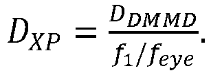
- One drawback of the folded double-telecentric relay design is that it provides no magnification to the image of the
DMD display 60. Therefore to get a desired system field of view, afield lens 18 may be added in front of theDMD display 60 to magnify the image. (Thedisplay 60 may be an emissive display, or maybe a reflective display that is illuminated through an illumination path.) The magnification introduced by thefield lens 18 is

- Based on the design goal, device specifications, and mechanical considerations, Table 1 lists the first-order system specifications for the designs of
Figs. 3A ,3B .Table 1. First-order system specifications for virtual display. Microdisplay 0.7" DMD, XGA resolution, 14µm pixel Deformable mirror defocus range 0 ∼ 1.2 diopters Accommodation Range 0 ∼ 3 diopters Field of view 40° (32.5°H x 24.5 °V) Relay lens focal length, f1 43.9 mm Eyepiece focal length, feye 27.8 mm Exit pupil diameter 6 mm - The optical see-through capabilities of the
systems 100, 200 may be realized by using beamsplitters to fold the virtual display optics (e.g.,DMD 60,field lens 18, relay lens group 20) out of the way. However, given that theeyepiece 12 in the present design has a short focal length, it was very difficult to design the system conventionally. - In the instant exemplary design, a more elegant solution was pursued. As shown in
Figs. 3C ,3D , theeyepiece 12 was designed as a wedge-shaped free-form plastic lens. The free-form prism eyepiece 12 may include three rotationally asymmetric surfaces, labeled as S1, S2, and S3, respectively. Considering the virtual display path,Fig. 3D , a ray from the intermediate image of thedisplay 60 is first refracted by the surface S3. After two consecutive reflections by surfaces S1 and S2, the ray is transmitted through the surface S1 and reaches the exit (eye) pupil of the system. The surface S1 desirably satisfies the condition of total internal reflection for all rays reflected on the surface S1. The surface S2 of theeyepiece 12 may be coated as a half mirror in order to facilitate the optical see-through capability. A free-form compensator 14, which may include two rotationally asymmetric surfaces, S2 and S4, may be cemented to theeyepiece 12 to compensate for the aberrations and distortions introduced to the rays from the real-world scene when the twopieces Fig. 3C . In addition, an optionalcylindrical lens 13 may be included with the free-form compensator 14 to help minimize aberrations and distortion for the see-through path. - To achieve the desired optical performance, MTF values were selected to evaluate the overall image sharpness. Since the virtual display system 100 was designed backwards from the
eyepiece 12 to thedisplay 60, the goal was to have MTF values no less than 20% at spatial frequency of 36 lp/mm on thedisplay 60, which is the cut-off frequency for pixel size of 14µm. The human eye has an angular resolution of 1 arcmin. Therefore thecompensator 14 was optimized such that the MTF values at 30 cycles/degree are greater than 0.2 to minimize degradation of the real-world scene. Another important optical performance factor of thesystem 100, 200 was image distortion. In conventional system, distortion is regular and can be compensated easily electronically or computationally. However in systems with off-axis freeform optics, the distortion can be very large and irregular. Therefore the design of thesystems 100, 200 should have tight constraints on distortion sampled over the entire FOV. The distortion is especially important for the see-through optical path, because it can change the sizes and shapes of objects seen through the see-through view, thus greatly affecting 3D perception. - The design of the
systems 100, 200 involved two steps, the virtual display path and the optical see-through path. For the virtual display path, thefreeform eyepiece 12 was setup with therelay lens 20 andfield lens 18 in CodeV and optimized together. The display performance was balanced for fields sampled across the 40-degrees of FOV and across the desired accommodation range of 3 diopters. After the virtual display optimization was finished, thefreeform eyepiece 12 was setup alone with thecompensator 14 and the compensator's back surface S4 was optimized for see-through performance. The see-through performance was optimized for 60 degrees of field of view while emphasizing the central 40 degrees. A progressive optimization strategy was adopted in both steps by gradually increasing the number of variable surface coefficients of the freeform surfaces as the system performance improved. - In the final design, the freeform eyepiece and compensator surfaces S1, S2, S3, S4 were described by XY-polynomials to the 10th order and prototyped by single-point diamond turning on PMMA. In the
system 200 ofFig. 3B , one of the field lenses elements, element 17, was optimized, and a diffractive optical feature was added to correct for chromatic aberrations introduced by thefreeform eyepiece 12. Allother lenses - The polychromatic MTF values of the virtual display, evaluated for a 3 mm pupil, are greater than 0.2 at 36 lp/mm across the 40 degrees of field of view with a central field value of 0.5,
Figs. 4A-4E . The virtual display also shows minimal distortion,Fig. 4F . The polychromatic MTF values of the see-through optical path, evaluated for 3 mm pupil, are greater than 0.4 at 30 cycles/degree across the 40 degrees of field of view,Figs. 5A-5E . The distortion of the see-through scene was also very well corrected,Fig. 5F . The prescription for the particular design ofFig. 3B is provided as follows. - In Table 2, surfaces #2 - #4 specify the free-
form eyepiece 12.Surface # 2 and #4 represent the same physical surface and is also denoted as eyepiece surface S1.Surface # 3 is also denoted as eyepiece surface S2, andSurface # 5 is also denoted as eyepiece surface S3. Surfaces #8 - #15 and surfaces #17 - #24 are the same group ofrelay lenses deformable mirror 80 is modeled atSurface # 16. Surfaces #25 - #26 model thebeam splitter 16 at 45 degrees. Surfaces #27 - #28 represent the field lens element 17, and Surfaces #29 - #30 represent thefield lens element 19.Table 2. System prescription for virtual display path. Element number used in figures Surface No. Surface Type Y Radius Thickness Material Refract Mode 1 (Stop) Sphere Infinity 0.000 Refract 12, S1 2 XY Poly -185.496 0.000 PMMA Refract 12, S2 3 XY Poly -67.446 0.000 PMMA Reflect 12, S1 4 XY Poly -185.496 0.000 PMMA Reflect 12, S3 5 XY Poly -830.046 0.000 Refract 6 Sphere Infinity 0.000 Refract 7 Sphere Infinity 53.933 Refract 24 8 Sphere 435.850 4.000 NSF10 Refract 9 Sphere 36.730 12.070 NBAF10 Refract 10 Sphere -53.760 18.079 Refract 22 11 Sphere 53.760 12.070 NBAF10 Refract 12 Sphere -36.730 4.000 NSF10 Refract 13 Sphere -435.850 19.826 Refract 26 14 Sphere Infinity 2.000 NBK7 Refract 15 Sphere 38.900 3.502 Refract 80 16 Sphere -4000.000 -3.502 Reflect 26 17 Sphere 38.900 -2.000 NBK7 Refract 18 Sphere Infinity -19.826 Refract 22 19 Sphere -435.850 -4.000 NSF10 Refract 20 Sphere -36.730 -12.070 NBAF10 Refract 21 Sphere 53.760 -18.079 Refract 24 22 Sphere -53.760 -12.070 NBAF10 Refract 23 Sphere 36.730 -4.000 NSF10 Refract 24 Sphere 435.850 -23.000 Refract 16 25 Sphere Infinity -1.600 471400.6541 Refract 26 Sphere Infinity -10.513 Refract 19 27 Sphere -46.700 -6.500 NBK7 Refract 28 Sphere Infinity -1.896 Refract 17 29 Asphere -102.223 -2.800 PMMA Refract 30 Asphere -61.641 -7.655 Refract - In Table 3 2
surfaces # 2 and #3 areeyepiece surfaces Surfaces # 4, #5 specify the free-form compensator 14.Surface # 4 is, it an exact replica of Surface #3 (eyepiece surface S3).Table 3. System prescription for see-through path. Element number used in figures Surface No. Surface Type Y Radius X Radius Thick -ness Material Refract Mode 1 (Stop) Sphere Infinity Infinity 0.000 Refract 12, S1 2 XY Poly -185.496 -185.496 0.000 PMMA Refract 12, S3 3 XY Poly -67.446 -67.446 0.000 PMMA Refract 14, S2 4 XY Poly -67.446 -67.446 0.000 PMMA Refract 14, S4 5 XY Poly -87.790 -87.790 10.00 0 Refract 13 6 Cylindrical Infinity -103.400 6.5 NBK7 Refract 13 7 Sphere Infinity Infinity 0.000 Refract - As used in the system prescription Tables, e.g., Table 2 or Table 3, the term "XY Poly" refers to a surface which may be respresented by the equation


Table 4. Optical surface prescription of Surface # 2 and #4 of Table 2.Y Radius -1.854965E+02 X**2 * Y**5 -1.505674E-10 Conic Constant -2.497467E+01 X * Y**6 0.000000E+00 X 0.000000E+00 Y**7 -4.419392E-11 Y 0.000000E+00 X**8 4.236650E-10 X**2 -2.331157E-03 X**7 * Y 0.000000E+00 X * Y 0.000000E+00 X**6 * Y**2 -1.079269E-10 Y**2 6.691726E-04 X**5 * Y**3 0.000000E+00 X**3 0.000000E+00 X**4 * Y**4 -1.678245E-10 X**2 * Y -1.066279E-04 X**3 * Y**5 0.000000E+00 X Y**2 0.000000E+00 X**2 * Y**6 2.198604E-12 Y**3 -2.956368E-05 X * Y**7 0.000000E+00 X**4 -1.554280E-06 Y**8 -2.415118E-12 X**3 * Y 0.000000E+00 X**9 0.000000E+00 X**2 * Y**2 1.107189E-06 X**8 * Y 4.113054E-12 X * Y**3 0.000000E+00 X**7 * Y**2 0.000000E+00 Y**4 1.579876E-07 X**6 * Y**3 -1.805964E-12 X**5 0.000000E+00 X**5 * Y**4 0.000000E+00 X**4 * Y 1.789364E-07 X**4 * Y**5 9.480632E-13 X**3 * Y**2 0.000000E+00 X**3 * Y**6 0.000000E+00 X**2 * Y**3 -2.609879E-07 X**2 * Y**7 2.891726E-13 X * Y**4 0.000000E+00 X * Y**8 0.000000E+00 Y**5 -6.129549E-10 Y**9 -2.962804E-14 X**6 -3.316779E-08 X**10 -6.030361E-13 X**5 * Y 0.000000E+00 X**9 * Y 0.000000E+00 X**4 * Y**2 9.498635E-09 X**8 * Y**2 -7.368710E-13 X**3 * Y**3 0.000000E+00 X**7 * Y**3 0.000000E+00 X**2 * Y**4 9.042084E-09 X**6 * Y**4 9.567750E-13 X * Y**5 0.000000E+00 X**5 * Y**5 0.000000E+00 Y**6 -4.013470E-10 X**4 * Y**6 4.280494E-14 X**7 0.000000E+00 X**3 * Y**7 0.000000E+00 X**6 * Y -8.112755E-10 X**2 * Y**8 -7.143578E-15 X**5 * Y**2 0.000000E+00 X * Y**9 0.000000E+00 X**4 * Y**3 1.251040E-09 Y**10 3.858414E-15 X**3 * Y**4 0.000000E+00 N-Radius 1.000000E+00 Table 5. Decenter of Surface # 2 and #4 of Table 2, relative to Surface #1 of Table 2.Y DECENTER Z DECENTER ALPHA TILT 6.775E+00 2.773E+01 7.711E+00 Table 6. Optical surface prescription of Surface # 3 of Table 2.Y Radius -6.744597E+01 X**2 * Y**5 -3.464751E-11 Conic Constant -1.258507E+00 X * Y**6 0.000000E+00 X 0.000000E+00 Y**7 -8.246179E-12 Y 0.000000E+00 X**8 -2.087865E-11 X**2 -1.300207E-03 X**7 * Y 0.000000E+00 X*Y 0.000000E+00 X**6 * Y**2 2.845323E-11 Y**2 4.658585E-04 X**5 * Y**3 0.000000E+00 X**3 0.000000E+00 X**4 * Y**4 -5.043398E-12 X**2 * Y -1.758475E-05 X**3 * Y**5 0.000000E+00 X Y**2 0.000000E+00 X**2 * Y**6 2.142939E-14 Y**3 -1.684923E-06 X * Y**7 0.000000E+00 X**4 -1.463720E-06 Y**8 1.607499E-12 X**3 * Y 0.000000E+00 X**9 0.000000E+00 X**2 * Y**2 -1.108359E-06 X**8 * Y -1.922597E-12 X * Y**3 0.000000E+00 X**7 * Y**2 0.000000E+00 Y**4 -1.098749E-07 X**6 * Y**3 1.100072E-13 X**5 0.000000E+00 X**5 * Y**4 0.000000E+00 X**4 * Y -7.146353E-08 X**4 * Y**5 -4.806130E-14 X**3 * Y**2 0.000000E+00 X**3 * Y**6 0.000000E+00 X**2 * Y**3 -1.150619E-08 X**2 * Y**7 -2.913177E-14 X * Y**4 0.000000E+00 X * Y**8 0.000000E+00 Y**5 5.911371E-09 Y**9 9.703717E-14 X**6 -5.406591E-10 X**10 2.032150E-13 X**5 * Y 0.000000E+00 X**9 * Y 0.000000E+00 X**4 * Y**2 -1.767107E-09 X**8 * Y**2 -1.037107E-13 X**3 * Y**3 0.000000E+00 X**7 * Y**3 0.000000E+00 X**2 * Y**4 -7.415334E-10 X**6 * Y**4 3.602862E-14 X * Y**5 0.000000E+00 X**5 * Y**5 0.000000E+00 Y**6 -5.442400E-10 X**4 * Y**6 -8.831469E-15 X**7 0.000000E+00 X**3 * Y**7 0.000000E+00 X**6 * Y 6.463414E-10 X**2 * Y**8 2.178095E-15 X**5 * Y**2 0.000000E+00 X * Y**9 0.000000E+00 X**4 * Y**3 1.421597E-10 Y**10 1.784074E-15 X**3 * Y**4 0.000000E+00 N-Radius 1.000000E+00 Table 7. Decenter of Surface # 3 of Table 2 relative to Surface #1 of Table 2.Y DECENTER Z DECENTER ALPHA TILT 1.329E+01 4.321E+01 -8.856E+00 Table 8. Optical surface prescription of Surface # 5 of Table 2.Y Radius -8.300457E+02 X**2 * Y**5 4.051880E-08 Conic Constant -9.675799E+00 X * Y**6 0.000000E+00 X 0.000000E+00 Y**7 -3.973293E-09 Y 0.000000E+00 X**8 -1.881791E-10 X**2 -1.798206E-04 X**7 * Y 0.000000E+00 X*Y 0.000000E+00 X**6 * Y**2 5.519986E-09 Y**2 -2.606383E-03 X**5 * Y**3 0.000000E+00 X**3 0.000000E+00 X**4 * Y**4 3.822268E-09 X**2 * Y -7.767146E-05 X**3 * Y**5 0.000000E+00 X Y**2 0.000000E+00 X**2 * Y**6 -3.024448E-09 Y**3 -8.958581E-05 X * Y**7 0.000000E+00 X**4 1.978414E-05 Y**8 2.673713E-11 X**3 * Y 0.000000E+00 X**9 0.000000E+00 X**2 * Y**2 2.081156E-05 X**8 * Y 1.006915E-10 X * Y**3 0.000000E+00 X**7 * Y**2 0.000000E+00 Y**4 -1.073001E-06 X**6 * Y**3 -2.945084E-10 X**5 0.000000E+00 X**5 * Y**4 0.000000E+00 X**4 * Y 2.585164E-07 X**4 * Y**5 5.958040E-10 X**3 * Y**2 0.000000E+00 X**3 * Y**6 0.000000E+00 X**2 * Y**3 -2.752516E-06 X**2 * Y**7 -3.211903E-10 X * Y**4 0.000000E+00 X * Y**8 0.000000E+00 Y**5 -1.470053E-06 Y**9 2.296303E-11 X**6 -1.116386E-07 X**10 5.221834E-12 X**5 * Y 0.000000E+00 X**9 * Y 0.000000E+00 X**4 * Y**2 -3.501439E-07 X**8 * Y**2 1.135044E-11 X**3 * Y**3 0.000000E+00 X**7 * Y**3 0.000000E+00 X**2 * Y**4 1.324057E-07 X**6 * Y**4 -1.050621E-10 X * Y**5 0.000000E+00 X**5 * Y**5 0.000000E+00 Y**6 -9.038017E-08 X**4 * Y**6 5.624902E-11 X**7 0.000000E+00 X**3 * Y**7 0.000000E+00 X**6 * Y 3.397174E-10 X**2 * Y**8 5.369592E-12 X**5 * Y**2 0.000000E+00 X * Y**9 0.000000E+00 X**4 * Y**3 -1.873966E-08 Y**10 2.497657E-12 X**3 * Y**4 0.000000E+00 N-Radius 1.000000E+00 Table 9. Decenter of Surface # 5 of Table 2 relative to Surface #1 of Table 2.Y DECENTER Z DECENTER ALPHA TILT .427E+01 3.347E+01 7.230E+01 - Turning to the prescription of the second field lens element 17, both surfaces of the field lens element 17 are aspheric surfaces. Additionally, Surface #29 (Table 2) of field lens element 17 has a kinoform diffractive optical feature which may be represented according to the following equation

Table 10. Surface Prescription for Surface #29 of Table 2. Y Radius 1.022230E+02 Conic Constant (K) 1.091191E+01 4th Order Coefficient (A) 4.372314E-06 6th Order Coefficient (B) -6.940740E-08 8th Order Coefficient (C) 8.588869E-11 10th Order Coefficient (D) 2.348571E-14 12th Order Coefficient (E) -1.463306E-16 Table 11. Diffractive Optical Element Phase Data for Surface #29 of Table 2. Construction Wavelength (nm) 525 R**2 (HCO C1) -1.295858E-03 R**4 (HCO C2) -3.879339E-07 R**6 (HCO C3) 8.494999E-09 R**8 (HCO C4) -1.771348E-13 R**10 (HCO C5) -3.584229E-15 Table 12. Surface Prescription for Surface # 30 of Table 2.Y Radius 6.164108E+01 Conic Constant (K) 9.828641E+00 4th Order Coefficient (A) 5.898651E-05 6th Order Coefficient (B) -2.951081E-07 8th Order Coefficient (C) -3.440910E-10 10th Order Coefficient (D) 1.785109E-13 12th Order Coefficient (E) 2.803121E-15 Table 13. Optical surface prescription of Surface # 5 of Table 3.Y Radius -8.779024E+01 X**2 * Y**5 -8.011955E-11 Conic Constant -7.055198E+00 X * Y**6 0.000000E+00 X 0.000000E+00 Y**7 3.606142E-11 Y 0.000000E+00 X**8 3.208020E-11 X**2 -3.191225E-03 X**7 * Y 0.000000E+00 X*Y 0.000000E+00 X**6 * Y**2 -2.180416E-11 Y**2 4.331992E-03 X**5 * Y**3 0.000000E+00 X**3 0.000000E+00 X**4 * Y**4 -3.616135E-11 X**2 * Y -9.609025E-05 X**3 * Y**5 0.000000E+00 X Y**2 0.000000E+00 X**2 * Y**6 -5.893434E-12 Y**3 -2.432809E-05 X * Y**7 0.000000E+00 X**4 -2.955089E-06 Y**8 3.081069E-12 X**3 * Y 0.000000E+00 X**9 0.000000E+00 X**2 * Y**2 2.096887E-07 X**8 * Y 1.267096E-12 X * Y**3 0.000000E+00 X**7 * Y**2 0.000000E+00 Y**4 -9.184356E-07 X**6 * Y**3 -1.848104E-12 X**5 0.000000E+00 X**5 * Y**4 0.000000E+00 X**4 * Y 3.707556E-08 X**4 * Y**5 5.208420E-14 X**3 * Y**2 0.000000E+00 X**3 * Y**6 0.000000E+00 X**2 * Y**3 -1.535357E-07 X**2 * Y**7 1.198597E-13 X * Y**4 0.000000E+00 X * Y**8 0.000000E+00 Y**5 -1.445904E-08 Y**9 -6.834914E-14 X**6 -4.440851E-09 X**10 -1.706677E-14 X**5 * Y 0.000000E+00 X**9 * Y 0.000000E+00 X**4 * Y**2 1.686424E-09 X**8 * Y**2 -1.614840E-14 X**3 * Y**3 0.000000E+00 X**7 * Y**3 0.000000E+00 X**2 * Y**4 6.770909E-09 X**6 * Y**4 8.739087E-14 X * Y**5 0.000000E+00 X**5 * Y**5 0.000000E+00 Y**6 -3.713094E-10 X**4 * Y**6 3.940903E-15 X**7 0.000000E+00 X**3 * Y**7 0.000000E+00 X**6 * Y -1.316067E-10 X**2 * Y**8 5.435162E-15 X**5 * Y**2 0.000000E+00 X * Y**9 0.000000E+00 X**4 * Y**3 7.924387E-10 Y**10 -2.259169E-15 X**3 * Y**4 0.000000E+00 N-Radius 1.000000E+00 Table 14. Decenter of Surface # 5 relative to Surface #1 of Table 3.Y DECENTER Z DECENTER ALPHA TILT 3.358E+00 4.900E+01 6.765E+00 - In the designs of
Figs. 3A ,3B above, an optionalcylindrical lens 13 has been included with the free-form compensator 14 to help minimize aberrations and distortion. An alternative design is also provided without thecylindrical lens 13, in which the virtual display path is the same as shown inFig. 3B and Table 2. The only difference among the remaining surfaces of the see-through path in the absence of thecylindrical lens 13 is the eyepiece/compensator surface S2 (Surface # 5 in the optical see-through path of Table 3). In Table 15,Surfaces # 2 and #3 are eyepiece surfaces S1 and S3, modeled the same as in the virtual display path. Surfaces #4 - 5 describe the free-form compensator 14.Surface # 4 is a exact replica ofSurface # 3.Table 15. Alternative eyepiece optics prescription without cylindrical lens. Surface Type Y Radius X Radius Thickness Material Refract Mode Object Sphere Infinity Infinity -666.700 Refract 1 (Stop) Sphere Infinity Infinity 0.000 Refract 2 XY Polynomial -185.496 -185.496 0.000 PMMA Refract 3 XY Polynomial -67.446 -67.446 0.000 PMMA Refract 4 XY Polynomial -67.446 -67.446 0.000 PMMA Refract 5 XY Polynomial -492.346 -492.346 0.000 Refract Image Sphere Infinity Infinity 0.000 Refract Table 16. Optical surface prescription of Surface # 5 of Table 15.Y Radius -4.923462E+02 X**2 * Y**5 -1.476237E-10 Conic Constant 3.982960E+00 X * Y**6 0.000000E+00 X 0.000000E+00 Y**7 2.044705E-11 Y 0.000000E+00 X**8 2.971746E-11 X**2 -3.001720E-03 X**7 * Y 0.000000E+00 X*Y 0.000000E+00 X**6 * Y**2 -6.199724E-12 Y**2 -5.233825E-04 X**5 * Y**3 0.000000E+00 X**3 0.000000E+00 X**4 * Y**4 -2.279723E-11 X**2 * Y -6.009699E-05 X**3 * Y**5 0.000000E+00 X Y**2 0.000000E+00 X**2 * Y**6 -1.041364E-12 Y**3 -2.244921E-05 X * Y**7 0.000000E+00 X**4 -6.379076E-07 Y**8 1.125487E-12 X**3 * Y 0.000000E+00 X**9 0.000000E+00 X**2 * Y**2 2.968752E-06 X**8 * Y 1.210373E-12 X * Y**3 0.000000E+00 X**7 * Y**2 0.000000E+00 Y**4 3.771516E-07 X**6 * Y**3 -1.331110E-12 X**5 0.000000E+00 X**5 * Y**4 0.000000E+00 X**4 * Y 5.359865E-08 X**4 * Y**5 -9.781602E-14 X**3 * Y**2 0.000000E+00 X**3 * Y**6 0.000000E+00 X**2 * Y**3 -1.965407E-07 X**2 * Y**7 4.515428E-13 X * Y**4 0.000000E+00 X * Y**8 0.000000E+00 Y**5 -7.301859E-09 Y**9 -5.050786E-14 X**6 -6.841269E-09 X**10 -1.058279E-14 X**5 * Y 0.000000E+00 X**9 * Y 0.000000E+00 X**4 * Y**2 -2.507411E-09 X**8 * Y**2 -2.975833E-14 X**3 * Y**3 0.000000E+00 X**7 * Y**3 0.000000E+00 X**2 * Y**4 4.627014E-10 X**6 * Y**4 6.309574E-14 X * Y**5 0.000000E+00 X**5 * Y**5 0.000000E+00 Y**6 -4.841692E-10 X**4 * Y**6 -1.214005E-15 X**7 0.000000E+00 X**3 * Y**7 0.000000E+00 X**6 * Y -3.343485E-10 X**2 * Y**8 1.180350E-14 X**5 * Y**2 0.000000E+00 X * Y**9 0.000000E+00 X**4 * Y**3 7.999315E-10 Y**10 -5.938353E-16 X**3 * Y**4 0.000000E+00 N-Radius 1.000000E+00 Table 17. Decenter of Surface # 5 of Table 15 relative to Surface #1 of Table 15.Y DECENTER Z DECENTER ALPHA TILT 4.618E+00 4.853E+01 7.007E+00 - A prototype of the multi-focal-
plane display system 200 ofFig. 3B was built with off-the-shelf lenses and customized optics, 3D views of which are provided inFigs. 6A, 6B . Thesystem 200 was folded to avoid conflicting with the viewer's head. Custom electronics were also developed to control and synchronize the display images on the DMD 60 (LUXBEAM® 4500, VISITECH, Drammen, Norway.), the illumination of the LED (not shown), and focal-plane switching of the deformable mirror 80 (OKO® Technologies MMDM10-1-focus, Flexible Optical B.V., Rijswijk, Netherlands). - A continuous 3D scene was rendered which was composed of a slanted planar object and a green floor grid, both extending from 0 to 2.5 diopters. The scene was decomposed onto 6 focal planes, placed at 3 diopter, 2.4 diopter, 1.8 diopter, 1.2 diopter, 0.6 diopter and 0 diopter, based on the targets' depth values, and a depth-fusing technique was used to blend the 6 focal planes into a smooth continuum. The whole 3D scene was refreshed at about 60 Hz; thus, flickering was not visible.
Figure 7A shows the actual 6-focal-plane scene as seen through the system; the image was sharp and had very low distortion. Without special algorithms, the pixels on different focal planes overlap and fuse smoothly due to the constant field of view design. In addition, a camera lens with shallow depth of field was used and manually focused at different parts of the scene. InFig. 7B , the resolution target was displayed on the back wall, and the camera was focused at about 2 m. The near end of the floor grid was out of focus and the back grids as well as the logos were in sharp focus. InFig. 7C , the resolution target was displayed on the front focal plane, the camera was focused at 30 cm, and now the near scene was in focus and the content on the back was blurred. Thus, the prototype was demonstrated to be capable of rendering 6 or more focal planes of high quality, high resolution color images at a flickering-free speed. It also had very good optical see-through performance for augmented reality applications, and has the potentially to provide higher depth perception accuracy, higher stereoacuity, and lower user fatigue. - In another aspect, which is not according to the present invention, an exemplary multi-focal-
plane display system 300 combining high-speed display technologies, such as Liquid Crystal on Silicon (LCOS) and Ferroelectric Liquid Crystal On Silicon (FLCoS) and a high-speed active refractive optical element, such as an electricaltunable lens 380, is provided. - The specific design is based on a 0.8" WXGA LCOS/
FLCOS display 360 and a 10 mm aperture electrical tunable lens 380 (Optotune EL-10-30, Optotune AG, Dietikon, Switzerland.)). Thetunable lens 380 changes shape when electrical current flows through thelens 380 to produce a change in optical power. TheOptotune lens 380 has a response time of about 2.5 ms and therefore potentially can be used in multi-focal-plane displays.Table 18. Design specification for tunable lens system. Microdisplay 0.8" LCOS/FLCOS WXGA, 14 µm pixel Tunable Lens 10 mm aperture, 12 diopter, focus range Virtual Display Field of view 50° (43.6°H x 26.4°V) Pupil size 10 mm Eye Clearance 20 mm (accommodates low-profile glasses) Image Quality (DMD space) MTF > 0.2 at 36 lp/mm (5 mm pupil) Display Distortion < 2.0 % Virtual Image Distance 33 cm ∼ Infinity f-number 2.2 - The final layout of the design is shown in
Figs. 10A-11 . A relay lens group (lenses spherical mirror 318, which acts as an eyepiece and forms a virtual image for a user. Optionally, themirror 318 may be aspherical. Abeamsplitter 316 is used to enable see-through capability. Thetunable lens 380 may provide the system stop and the system may be telecentric to themicrodisplay 360 due to the requirements of LCOS/FLCoS. Enough space is also given for anillumination beamsplitter 317,Fig. 11 . The prescription of thesystem 300 is provided in Table 19 - Table 26. (In Table 19, surfaces #9 - 12 model the Optotune electrictunable lens 380.) The performance of the system is illustrated inFigs. 12A ,12B .Table 19. Tunable lens system prescription. Element number used in figures Surface No. Surface Type Y Radius Thickness Material Refract Mode 1 (Stop) Sphere Infinity 44.000 Refract 2 Sphere Infinity -24.000 Reflect 318 3 Sphere 68.000 34.000 Reflect 316 4 Sphere Infinity 17.371 Refract 310 5 Asphere -23.777 6.000 PMMA Refract 6 Asphere 363.193 0.100 Refract 308 7 Sphere 39.587 6.000 NSF11 Refract 8 Sphere -119.109 4.385 Refract 380 9 Sphere Infinity 0.500 BK7 Refract 380 10 Sphere Infinity 4.377 Refract 380 11 Sphere 30.270 2.023 'OL1024' Refract 380 12 Sphere Infinity 0.500 BK7 Refract 13 Sphere Infinity 3.724 Refract 306 14 Asphere -24.004 5.999 Polystyrene Refract 15 Asphere 27.079 0.251 Refract 304 16 Sphere 38.710 5.944 Zeonex ZE48R Refract 17 Sphere -21.557 5.631 Refract 302 18 Asphere 33.959 9.698 Zeonex ZE48R Refract 19 Asphere -21.555 29.000 Refract Table 20. Surface Prescription for Surface # 5 of Table 19.Y Radius -23.777 Conic Constant (K) 2.040996E+00 4th Order Coefficient (A) 1.385342E-04 6th Order Coefficient (B) -1.022594E-06 8th Order Coefficient (C) 8.784855E-09 10th Order Coefficient (D) -2.891372E-11 Table 21. Surface Prescription for Surface #6 of Table 19. Y Radius 363.193 Conic Constant (K) -1.060606E+01 4th Order Coefficient (A) 6.247531E-05 6th Order Coefficient (B) -8.622953E-07 8th Order Coefficient (C) 9.037984E-09 10th Order Coefficient (D) -4.513968E-11 Table 22. Surface Prescription for Surface # 14 of Table 19.Y Radius -24.004 Conic Constant (K) 2.609562E+00 4th Order Coefficient (A) -1.053175E-04 6th Order Coefficient (B) 3.126004E-07 8th Order Coefficient (C) -2.716200E-08 10th Order Coefficient (D) 2.112687E-10 Table 23. Surface Prescription for Surface # 15 of Table 19.Y Radius 27.079 Conic Constant (K) -6.178694E+00 4th Order Coefficient (A) -1.075797E-05 6th Order Coefficient (B) -1.383769E-07 8th Order Coefficient (C) 4.641779E-10 10th Order Coefficient (D) 9.831856E-13 Table 24. Surface Prescription for Surface # 16 of Table 19.Construction Wavelength (nm) 589 R**2 (HCO C1) -1.543448E-03 R**4 (HCO C2) 7.864956E-06 R**6 (HCO C3) -1.080042E-07 R**8 (HCO C4) 1.272753E-09 R**10 (HCO C5) -5.114979E-12 Table 25. Surface Prescription for Surface # 18 of Table 19.Y Radius 33.959 Conic Constant (K) 2.310849E+00 4th Order Coefficient (A) 4.222932E-06 6th Order Coefficient (B) -2.501786E-08 8th Order Coefficient (C) 3.154900E-11 10th Order Coefficient (D) 2.517705E-13 Table 26. Surface Prescription for Surface # 19 of Table 19.Y Radius -21.555 Conic Constant (K) -1.347355E+00 4th Order Coefficient (A) 1.944341E-05 6th Order Coefficient (B) 3.600425E-08 8th Order Coefficient (C) -1.998220E-11 10th Order Coefficient (D) 6.798072E-13 - In another of its aspects the present invention relates to new criteria for determining depth-fused display (DFD) system design parameters. The optical quality of a fused pixel in DFD displays is quantified by the point spread function (PSF) of its retinal image, or, equivalently, by the modulation transfer function (MTF) which is characterized by the ratio of the contrast modulation of the retinal image to that of a sinusoidal object on the 3D display. For instance, when the eye is accommodated at a rendered depth, z, the PSF of a fused pixel, PSF12, by two pixels on a pair of adjacent focal planes located at z1 and z2, respectively, may be described as the weighted sum of the PSFs from the front and the back pixels as:

- An example of the MTF plots of simulated retinal images of a dual-focal-plane DFD display is shown in
Fig. 8A . In the simulation, the two focal planes were placed at 1.2 diopters and 1.8 diopters, respectively, and the luminance ratio between the two focal planes was 1:1, indicating that the fused pixel was being simulated at the dioptric midpoint of the front and back focal planes, i.e., 1.5 diopters. To concentrate on the effects of depth fusion, an eye model was selected with a 3 mm pupil, with all residual aberrations removed.Figure 8A shows how the MTF of the retinal image changes as the eye accommodates at various positions between the two focal planes.Figure 8B shows the contrast gradient as a function of eye accommodation distance for different spatial frequencies, and the peak contrast for each frequency was marked by a black square marker. A transition frequency of around 17 cycles/degree (cpd) is observed from both plots. Below that transition frequency, the MTF of the retinal image is maximized at the dioptric midpoint of 1.5 diopters, which is the simulated depth by the 1:1 luminance ratio in the dual-focal plane system. Furthermore, as the eye approaches the simulated depth from either the far or near focal planes, the MTF values increase smoothly, providing the appropriate contrast gradient required for driving the eye accommodation. For frequencies higher than 17 cpd, however, the contrast of the fused pixel is always highest when the eye is accommodated at or near the physical focal planes, meaning that the contrast gradient has the tendency to drive the accommodation away from the simulated pixel depth, therefore creating a conflict accommodation cue.Figures 9A, 9B show how the transition frequency varies as a function of focal plane separation and as a function of pupil size.Figure 9A assumes a 3 mm eye pupil, andFig. 9B assumes a constant focal plane separation of 0.6 diopters. The results suggest that the smaller the focal plane separation and the smaller the designed eye pupil size, the higher in frequency the transition point is. Therefore a critical criterion for designing a DFD display is that the focal plane separation and the display's working pupil size should be determined such that the contrast gradient reverse point is higher than the system's cut-off frequency to avoid presenting a conflicting accommodation cue to the viewer. For instance, a 0.6-diopter separation between adjacent focal planes can be considered adequate for a DFD display affording an angular resolution of 1.8 arc minutes per pixel (approximately a spatial frequency of 17 cpd) and luminance greater than 10 cd/m2. The stimulation of 10 cd/m2 display luminance leads to approximately a 3 mm eye pupil diameter. A 0.45-diopter spacing or smaller would be desired for displays affording an angular resolution of 1 arc minute per pixel (i.e., 30 cpd). The smaller the angular resolution per pixel or the lower the image brightness, the smaller the required focal-plane separation would be. - These and other advantages of the present invention will be apparent to those skilled in the art from the foregoing specification. Accordingly, it will be recognized by those skilled in the art that changes or modifications may be made to the above-described embodiments without departing from the broad inventive concepts of the invention. It should therefore be understood that this invention is not limited to the particular embodiments described herein, but is intended to include all changes and modifications that are within the scope of the invention as set forth in the claims.
Claims (7)
- A virtual display system (100, 200) with addressable focus cues, comprisinga microdisplay (60) for providing a virtual image for display to a user;a reflective active optical element (80) configured to provide a variable optical power;a relay lens (21, 22, 24, 26) disposed along an optical path between the microdisplay (60) and the reflective active optical element (80), the relay lens (21, 22, 24, 26) being positioned therebetween such that the microdisplay (60) and an intermediate image of the microdisplay (60) are disposed at conjugate planes of the relay lens (21, 22, 24, 26), the relay lens (21, 22, 24, 26) being arranged in combination with the reflective active optical element (80) to provide a folded, double-telecentric system (20) such that a change of optical power on the optical element (80) changes only the location of the intermediate image without changing the image magnification, the field of view of the system or the angular resolution in eye space, and such that corresponding pixels on multiple focal planes overlap with each other one-to-one;a beamsplitter (16) disposed along the optical path between the microdisplay (60) and the active optical element (80) at an orientation to receive optical radiation from the active optical element (80)characterized in thatthe virtual display system further comprises a see-through eyepiece (12) being a freeform prism, the see-through eyepiece comprising
a selected surface (S2) configured to receive optical radiation from the beamsplitter (16) and reflect the received radiation to an exit pupil of the system, wherein the eyepiece (12) relays a stop of the virtual display system defined by the reflective active optical element (80) to form the exit pupil, and wherein the selected surface (S2) is also configured to receive optical radiation from a source other than the microdisplay (60) and to transmit such optical radiation to the exit pupil to provide a see-through optical path. - The display system of claim 1, wherein the eyepiece (12) comprises a first surface configured to receive and refract optical radiation from the beamsplitter (16) and comprises a second surface configured to receive the refracted optical radiation from the first surface, the second surface configured to reflect the optical radiation to the selected surface of the eyepiece (12).
- The display system of claim 2, wherein the second surface is configured to totally internally reflect the optical radiation.
- The display system of any one of the preceding claims, wherein one or more of the surfaces of the eyepiece (12) comprise a rotationally asymmetric surface.
- The display system of any one of the preceding claims, comprising an eyepiece compensator (14) disposed along the see-through path adjacent the selected surface of the eyepiece (12).
- The display system of any one of the preceding claims, comprising a field lens (18) disposed adjacent the microdisplay (60) configured to provide magnification of the display.
- The display system of claim 6, wherein the field lens comprises an aspheric surface and a diffractive optical feature.
Applications Claiming Priority (2)
| Application Number | Priority Date | Filing Date | Title |
|---|---|---|---|
| US201261795500P | 2012-10-18 | 2012-10-18 | |
| PCT/US2013/065422 WO2014062912A1 (en) | 2012-10-18 | 2013-10-17 | Stereoscopic displays with addressable focus cues |
Publications (3)
| Publication Number | Publication Date |
|---|---|
| EP2910022A1 EP2910022A1 (en) | 2015-08-26 |
| EP2910022A4 EP2910022A4 (en) | 2016-09-14 |
| EP2910022B1 true EP2910022B1 (en) | 2023-07-12 |
Family
ID=50488746
Family Applications (1)
| Application Number | Title | Priority Date | Filing Date |
|---|---|---|---|
| EP13847218.8A Active EP2910022B1 (en) | 2012-10-18 | 2013-10-17 | Stereoscopic displays with addressable focus cues |
Country Status (11)
| Country | Link |
|---|---|
| US (4) | US9874760B2 (en) |
| EP (1) | EP2910022B1 (en) |
| JP (3) | JP6525880B2 (en) |
| KR (2) | KR102344903B1 (en) |
| CN (2) | CN110022472B (en) |
| AU (4) | AU2013331179B2 (en) |
| CA (2) | CA3102710A1 (en) |
| IL (3) | IL276021B2 (en) |
| IN (1) | IN2015DN02476A (en) |
| NZ (3) | NZ739225A (en) |
| WO (1) | WO2014062912A1 (en) |
Families Citing this family (68)
| Publication number | Priority date | Publication date | Assignee | Title |
|---|---|---|---|---|
| AU2009206514A1 (en) | 2008-01-22 | 2009-07-30 | The Arizona Board Of Regents On Behalf Of The University Of Arizona | Head-mounted projection display using reflective microdisplays |
| US9866826B2 (en) | 2014-11-25 | 2018-01-09 | Ricoh Company, Ltd. | Content-adaptive multi-focal display |
| US9865043B2 (en) * | 2008-03-26 | 2018-01-09 | Ricoh Company, Ltd. | Adaptive image acquisition and display using multi-focal display |
| US20120081800A1 (en) | 2009-04-20 | 2012-04-05 | Dewen Cheng | Optical see-through free-form head-mounted display |
| US20110075257A1 (en) | 2009-09-14 | 2011-03-31 | The Arizona Board Of Regents On Behalf Of The University Of Arizona | 3-Dimensional electro-optical see-through displays |
| DE102017203492A1 (en) * | 2017-03-03 | 2018-09-06 | Witec Wissenschaftliche Instrumente Und Technologie Gmbh | Method and device for imaging a sample surface |
| CN102782562B (en) | 2010-04-30 | 2015-07-22 | 北京理工大学 | Wide-field-of-view high-resolution splicing helmet-mounted display device |
| US10156722B2 (en) * | 2010-12-24 | 2018-12-18 | Magic Leap, Inc. | Methods and systems for displaying stereoscopy with a freeform optical system with addressable focus for virtual and augmented reality |
| EP3270194B1 (en) | 2012-01-24 | 2020-10-14 | The Arizona Board of Regents on behalf of The University of Arizona | Compact eye-tracked head-mounted display |
| JP6525880B2 (en) | 2012-10-18 | 2019-06-05 | アリゾナ ボード オブ リージェンツ オン ビハーフ オブ ザ ユニバーシティ オブ アリゾナ | Stereoscopic display with addressable focus cues |
| US9699433B2 (en) | 2013-01-24 | 2017-07-04 | Yuchen Zhou | Method and apparatus to produce re-focusable vision with detecting re-focusing event from human eye |
| TWI625551B (en) * | 2013-03-15 | 2018-06-01 | 傲思丹度科技公司 | 3d light field displays and methods with improved viewing angle depth and resolution |
| US9857591B2 (en) | 2014-05-30 | 2018-01-02 | Magic Leap, Inc. | Methods and system for creating focal planes in virtual and augmented reality |
| US9915826B2 (en) | 2013-11-27 | 2018-03-13 | Magic Leap, Inc. | Virtual and augmented reality systems and methods having improved diffractive grating structures |
| CN110376743B (en) | 2014-01-31 | 2022-03-04 | 奇跃公司 | Multi-focus display system and method |
| US10386636B2 (en) * | 2014-01-31 | 2019-08-20 | Magic Leap, Inc. | Multi-focal display system and method |
| AU2015227092B2 (en) | 2014-03-05 | 2019-07-04 | Arizona Board Of Regents On Behalf Of The University Of Arizona | Wearable 3D augmented reality display |
| CN106664400B (en) * | 2014-05-30 | 2020-08-04 | 奇跃公司 | Method and system for displaying stereoscopic vision for virtual and augmented reality |
| CA3114696A1 (en) | 2014-05-30 | 2015-12-03 | Magic Leap, Inc. | Methods and system for creating focal planes in virtual and augmented reality |
| US9864205B2 (en) * | 2014-11-25 | 2018-01-09 | Ricoh Company, Ltd. | Multifocal display |
| AU2016211623B2 (en) | 2015-01-26 | 2020-04-16 | Magic Leap, Inc. | Virtual and augmented reality systems and methods having improved diffractive grating structures |
| US10176961B2 (en) | 2015-02-09 | 2019-01-08 | The Arizona Board Of Regents On Behalf Of The University Of Arizona | Small portable night vision system |
| US9848127B2 (en) * | 2015-07-14 | 2017-12-19 | Honeywell International Inc. | System and method for a compact display |
| US10204451B2 (en) * | 2015-11-30 | 2019-02-12 | Microsoft Technology Licensing, Llc | Multi-optical surface optical design |
| KR102762118B1 (en) * | 2015-12-28 | 2025-02-03 | 시리얼 테크놀로지즈 에스.에이. | Display device and method for optimizing image quality |
| US11320900B2 (en) | 2016-03-04 | 2022-05-03 | Magic Leap, Inc. | Current drain reduction in AR/VR display systems |
| EP3433661A4 (en) | 2016-03-25 | 2019-11-20 | Magic Leap, Inc. | SYSTEMS AND METHODS FOR VIRTUAL AND INCREASED REALITY |
| CA3018782A1 (en) | 2016-04-07 | 2017-10-12 | Magic Leap, Inc. | Systems and methods for augmented reality |
| CN105929537A (en) * | 2016-04-08 | 2016-09-07 | 北京骁龙科技有限公司 | Head-mounted display and eyepiece system thereof |
| WO2017192887A2 (en) * | 2016-05-04 | 2017-11-09 | The Regents Of The University Of California | Pseudo light-field display apparatus |
| CA3033651C (en) | 2016-08-12 | 2023-09-05 | Arizona Board Of Regents On Behalf Of The University Of Arizona | High-resolution freeform eyepiece design with a large exit pupil |
| WO2018043625A1 (en) * | 2016-08-31 | 2018-03-08 | パナソニックIpマネジメント株式会社 | Display device |
| RU2650086C1 (en) | 2016-12-22 | 2018-04-06 | Самсунг Электроникс Ко., Лтд. | Holographic image display device and a method of operation of a control unit contained in it |
| CN110914741A (en) * | 2017-03-09 | 2020-03-24 | 亚利桑那大学评议会 | Free form prism and head mounted display with increased field of view |
| AU2018231083B2 (en) | 2017-03-09 | 2023-03-09 | Arizona Board Of Regents On Behalf Of The University Of Arizona | Head-mounted light field display with integral imaging and waveguide prism |
| AU2018231081B2 (en) | 2017-03-09 | 2023-03-09 | Arizona Board Of Regents On Behalf Of The University Of Arizona | Head-mounted light field display with integral imaging and relay optics |
| CA3063710A1 (en) * | 2017-05-18 | 2018-11-22 | Arizona Board Of Regents On Behalf Of The University Of Arizona | Multilayer high-dynamic-range head-mounted display |
| CN111065957B (en) * | 2017-08-23 | 2022-04-05 | 交互数字麦迪逊专利控股公司 | Light field image engine method and apparatus for generating projected 3D light fields |
| JP7278277B2 (en) | 2017-11-02 | 2023-05-19 | ピーシーエムエス ホールディングス インコーポレイテッド | Method and system for aperture enlargement in light field displays |
| EP3726277B1 (en) | 2017-12-11 | 2025-12-17 | Panasonic Automotive Systems Co., Ltd. | Head-up display and moving body with head-up display mounted thereon |
| JP7233009B2 (en) * | 2017-12-11 | 2023-03-06 | パナソニックIpマネジメント株式会社 | Head-up displays and moving objects with head-up displays |
| CN109932806B (en) * | 2017-12-18 | 2021-06-08 | 中强光电股份有限公司 | Optical lens |
| CN109932820A (en) * | 2017-12-18 | 2019-06-25 | 中强光电股份有限公司 | monitor |
| CN107861247B (en) * | 2017-12-22 | 2020-08-25 | 联想(北京)有限公司 | Optical component and augmented reality device |
| WO2019182592A1 (en) | 2018-03-22 | 2019-09-26 | Arizona Board Of Regents On Behalf Of The University Of Arizona | Methods of rendering light field images for integral-imaging-based light filed display |
| KR20190118846A (en) | 2018-04-11 | 2019-10-21 | 한국과학기술연구원 | Multi-focal augmented reality device |
| US10529117B2 (en) * | 2018-04-16 | 2020-01-07 | Facebook Technologies, Llc | Systems and methods for rendering optical distortion effects |
| US11966055B2 (en) | 2018-07-19 | 2024-04-23 | Magic Leap, Inc. | Content interaction driven by eye metrics |
| CN110618529A (en) * | 2018-09-17 | 2019-12-27 | 武汉美讯半导体有限公司 | Light field display system for augmented reality and augmented reality device |
| WO2020095652A1 (en) * | 2018-11-09 | 2020-05-14 | ソニー株式会社 | Observation optical system and image display device |
| US11698516B2 (en) * | 2018-11-27 | 2023-07-11 | National Taiwan University | Head mounted display device and near-eye light field display device thereof |
| CN111624767B (en) * | 2019-02-28 | 2022-03-04 | 京东方科技集团股份有限公司 | near-eye display device |
| US11852813B2 (en) * | 2019-04-12 | 2023-12-26 | Nvidia Corporation | Prescription augmented reality display |
| KR102894906B1 (en) | 2019-06-07 | 2025-12-04 | 피씨엠에스 홀딩스, 인크. | Optical methods and systems for light field displays based on dispersive apertures |
| EP3990972A1 (en) | 2019-06-28 | 2022-05-04 | PCMS Holdings, Inc. | Optical method and system for light field (lf) displays based on tunable liquid crystal (lc) diffusers |
| JP7353625B2 (en) | 2019-09-06 | 2023-10-02 | 国立大学法人群馬大学 | volumetric display |
| US10989927B2 (en) * | 2019-09-19 | 2021-04-27 | Facebook Technologies, Llc | Image frame synchronization in a near eye display |
| KR102284743B1 (en) * | 2020-05-14 | 2021-08-03 | 한국과학기술연구원 | Extended dof image display apparatus and method for controlling thereof |
| CN112255809A (en) * | 2020-11-20 | 2021-01-22 | 浙江水晶光电科技股份有限公司 | Lens group and near-to-eye display device |
| JP7600756B2 (en) * | 2021-02-26 | 2024-12-17 | セイコーエプソン株式会社 | Optical unit and image display device |
| CN113341555B (en) * | 2021-08-02 | 2022-08-05 | 深圳纳德光学有限公司 | Reflective eyepiece optical system and head-mounted near-eye display device |
| CN113325566B (en) * | 2021-08-02 | 2022-08-05 | 深圳纳德光学有限公司 | Reflective eyepiece optical system and head-mounted near-to-eye display device |
| CN113341558B (en) * | 2021-08-02 | 2022-08-05 | 深圳纳德光学有限公司 | Reflective eyepiece optical system and head-mounted near-to-eye display device |
| KR20230043612A (en) * | 2021-09-24 | 2023-03-31 | 삼성전자주식회사 | See-through type display device and augmented reality apparatus including the same |
| CN116413911B (en) * | 2021-12-31 | 2025-08-01 | 北京耐德佳显示技术有限公司 | Ultra-thin lens, virtual image imaging device using same and near-eye display |
| US20240004199A1 (en) * | 2022-07-01 | 2024-01-04 | Google Llc | Partially curved lightguide with pupil replicators |
| US12445588B2 (en) * | 2023-06-01 | 2025-10-14 | Adeia Guides Inc. | Adaptive displays to address the vergence-accommodation conflict |
| US12028509B1 (en) * | 2023-12-04 | 2024-07-02 | Mloptic Corp. | Diffraction-limited optical target system with continuously-variable virtual distance |
Family Cites Families (159)
| Publication number | Priority date | Publication date | Assignee | Title |
|---|---|---|---|---|
| US3632184A (en) | 1970-03-02 | 1972-01-04 | Bell Telephone Labor Inc | Three-dimensional display |
| JPS503354A (en) | 1973-05-11 | 1975-01-14 | ||
| EP0066402B1 (en) | 1981-05-29 | 1985-09-11 | Gec Avionics Limited | Night vision goggles |
| US4669810A (en) | 1984-02-03 | 1987-06-02 | Flight Dynamics, Inc. | Head up display system |
| US4753522A (en) | 1985-06-03 | 1988-06-28 | Ricoh Company, Ltd. | Plastic lens assembly for use in copying machines |
| US4863251A (en) | 1987-03-13 | 1989-09-05 | Xerox Corporation | Double gauss lens for a raster input scanner |
| US5880888A (en) | 1989-01-23 | 1999-03-09 | Hughes Aircraft Company | Helmet mounted display system |
| GB8916206D0 (en) | 1989-07-14 | 1989-11-08 | Marconi Gec Ltd | Helmet systems |
| JP2692996B2 (en) | 1989-12-25 | 1997-12-17 | オリンパス光学工業株式会社 | Imaging lens |
| US5109469A (en) * | 1990-11-01 | 1992-04-28 | Itt Corporation | Phosphor screen for correcting luminous non-uniformity and method for making same |
| US5172275A (en) | 1990-12-14 | 1992-12-15 | Eastman Kodak Company | Apochromatic relay lens systems suitable for use in a high definition telecine apparatus |
| DE4291016T1 (en) | 1991-04-22 | 1993-05-13 | Evans & Sutherland Computer Corp., Salt Lake City, Utah, Us | |
| EP0566001B1 (en) * | 1992-04-07 | 1999-07-14 | Raytheon Company | Wide spectral bandwidth virtual image display optical system |
| US6008781A (en) * | 1992-10-22 | 1999-12-28 | Board Of Regents Of The University Of Washington | Virtual retinal display |
| US5526183A (en) | 1993-11-29 | 1996-06-11 | Hughes Electronics | Helmet visor display employing reflective, refractive and diffractive optical elements |
| US5416315A (en) | 1994-01-24 | 1995-05-16 | Night Vision General Partnership | Visor-mounted night vision visor |
| JP3359152B2 (en) * | 1994-05-13 | 2002-12-24 | キヤノン株式会社 | Display device |
| US7262919B1 (en) | 1994-06-13 | 2007-08-28 | Canon Kabushiki Kaisha | Head-up display device with curved optical surface having total reflection |
| US5621572A (en) | 1994-08-24 | 1997-04-15 | Fergason; James L. | Optical system for a head mounted display using a retro-reflector and method of displaying an image |
| JPH08160345A (en) | 1994-12-05 | 1996-06-21 | Olympus Optical Co Ltd | Head mounted display device |
| US5625495A (en) | 1994-12-07 | 1997-04-29 | U.S. Precision Lens Inc. | Telecentric lens systems for forming an image of an object composed of pixels |
| JP3658034B2 (en) | 1995-02-28 | 2005-06-08 | キヤノン株式会社 | Image observation optical system and imaging optical system |
| US5818632A (en) | 1995-04-13 | 1998-10-06 | Melles Griot, Inc | Multi-element lens system |
| JP3599828B2 (en) | 1995-05-18 | 2004-12-08 | オリンパス株式会社 | Optical device |
| US6469683B1 (en) | 1996-01-17 | 2002-10-22 | Nippon Telegraph And Telephone Corporation | Liquid crystal optical device |
| JP3556389B2 (en) | 1996-05-01 | 2004-08-18 | 日本電信電話株式会社 | Head mounted display device |
| JPH09218375A (en) | 1996-02-08 | 1997-08-19 | Canon Inc | Fatigue determination method and observation device using the same |
| JPH09219832A (en) | 1996-02-13 | 1997-08-19 | Olympus Optical Co Ltd | Image display |
| US5959780A (en) | 1996-04-15 | 1999-09-28 | Olympus Optical Co., Ltd. | Head-mounted display apparatus comprising a rotationally asymmetric surface |
| JP3758265B2 (en) | 1996-04-24 | 2006-03-22 | ソニー株式会社 | 3D image display method and display device thereof |
| US5880711A (en) | 1996-04-24 | 1999-03-09 | Sony Corporation | Three-dimensional image display method and its display apparatus |
| US6028606A (en) | 1996-08-02 | 2000-02-22 | The Board Of Trustees Of The Leland Stanford Junior University | Camera simulation system |
| JP3924348B2 (en) | 1996-11-05 | 2007-06-06 | オリンパス株式会社 | Image display device |
| US6034823A (en) | 1997-02-07 | 2000-03-07 | Olympus Optical Co., Ltd. | Decentered prism optical system |
| JPH10307263A (en) | 1997-05-07 | 1998-11-17 | Olympus Optical Co Ltd | Prism optical element and image observation device |
| US6760169B2 (en) | 1997-05-07 | 2004-07-06 | Olympus Corporation | Prism optical element, image observation apparatus and image display apparatus |
| WO1999023647A1 (en) | 1997-11-05 | 1999-05-14 | Omd Devices, L.L.C. | Focus error correction apparatus |
| CN1132039C (en) | 1997-12-11 | 2003-12-24 | 皇家菲利浦电子有限公司 | Image display device and head-mounted display including the same |
| US6236521B1 (en) | 1998-02-09 | 2001-05-22 | Canon Kabushiki Kaisha | Objective lens and image pickup device using the same |
| US6198577B1 (en) | 1998-03-10 | 2001-03-06 | Glaxo Wellcome, Inc. | Doubly telecentric lens and imaging system for multiwell plates |
| JP3279265B2 (en) | 1998-03-26 | 2002-04-30 | 株式会社エム・アール・システム研究所 | Image display device |
| US6704149B2 (en) | 1998-04-21 | 2004-03-09 | Minolta Co., Ltd. | Lens optical system |
| JPH11326820A (en) | 1998-05-18 | 1999-11-26 | Olympus Optical Co Ltd | Observing optical system and observing device using it |
| JP2000075240A (en) | 1998-08-26 | 2000-03-14 | Mr System Kenkyusho:Kk | Composite display |
| JP2000199853A (en) | 1998-10-26 | 2000-07-18 | Olympus Optical Co Ltd | Image-formation optical system and observation optical system |
| US6281862B1 (en) | 1998-11-09 | 2001-08-28 | University Of Washington | Scanned beam display with adjustable accommodation |
| JP2000171714A (en) | 1998-12-07 | 2000-06-23 | Olympus Optical Co Ltd | Image-formation optical system |
| US6433760B1 (en) | 1999-01-14 | 2002-08-13 | University Of Central Florida | Head mounted display with eyetracking capability |
| JP4550184B2 (en) | 1999-07-02 | 2010-09-22 | オリンパス株式会社 | Observation optical system |
| JP2000231060A (en) | 1999-02-12 | 2000-08-22 | Olympus Optical Co Ltd | Image-formation optical system |
| JP2000249974A (en) | 1999-03-02 | 2000-09-14 | Canon Inc | Display device and stereoscopic display device |
| CN100339739C (en) | 1999-04-02 | 2007-09-26 | 奥林巴斯株式会社 | Viewing optical system and image display comprising the same |
| EP1054280A3 (en) | 1999-05-20 | 2004-08-18 | Konica Corporation | Zoom lens |
| JP2001066543A (en) | 1999-08-25 | 2001-03-16 | Canon Inc | Composite optical device |
| US6243199B1 (en) | 1999-09-07 | 2001-06-05 | Moxtek | Broad band wire grid polarizing beam splitter for use in the visible wavelength region |
| JP3391342B2 (en) | 1999-10-29 | 2003-03-31 | ミノルタ株式会社 | Imaging lens device |
| JP2001145127A (en) | 1999-11-12 | 2001-05-25 | Shunichi Suda | Three-dimensional image display device |
| JP3854763B2 (en) | 1999-11-19 | 2006-12-06 | キヤノン株式会社 | Image display device |
| KR100360592B1 (en) | 1999-12-08 | 2002-11-13 | 동부전자 주식회사 | Semiconductor devic and method for fabricating it |
| JP2001238229A (en) | 2000-02-21 | 2001-08-31 | Nippon Hoso Kyokai <Nhk> | Stereoscopic image photographing device, stereoscopic image display device, and stereoscopic image photographing display system |
| US20010048561A1 (en) | 2000-08-24 | 2001-12-06 | Heacock Gregory L. | Virtual imaging system for small font text |
| JP2002031776A (en) * | 2000-07-14 | 2002-01-31 | Canon Inc | Display device |
| KR100386725B1 (en) | 2000-07-31 | 2003-06-09 | 주식회사 대양이앤씨 | Optical System for Head Mount Display |
| JP3658295B2 (en) | 2000-08-09 | 2005-06-08 | キヤノン株式会社 | Image display device |
| AU8709801A (en) | 2000-09-07 | 2002-03-22 | Actuality Systems Inc | Volumetric three-dimensional display system |
| JP4583569B2 (en) * | 2000-09-22 | 2010-11-17 | オリンパス株式会社 | Observation optical system and imaging optical system |
| JP4646374B2 (en) | 2000-09-29 | 2011-03-09 | オリンパス株式会社 | Image observation optical system |
| US6563648B2 (en) | 2000-10-20 | 2003-05-13 | Three-Five Systems, Inc. | Compact wide field of view imaging system |
| JP2002148559A (en) | 2000-11-15 | 2002-05-22 | Mixed Reality Systems Laboratory Inc | Image observing device and image observing system using the device |
| JP4943580B2 (en) | 2000-12-25 | 2012-05-30 | オリンパス株式会社 | Imaging optics |
| JP3658330B2 (en) | 2001-02-21 | 2005-06-08 | キヤノン株式会社 | Composite display device and head mounted display device using the same |
| JP2002258208A (en) | 2001-03-01 | 2002-09-11 | Mixed Reality Systems Laboratory Inc | Optical element and composite display device utilizing it |
| US6529331B2 (en) | 2001-04-20 | 2003-03-04 | Johns Hopkins University | Head mounted display with full field of view and high resolution |
| US6963454B1 (en) | 2002-03-01 | 2005-11-08 | Research Foundation Of The University Of Central Florida | Head-mounted display by integration of phase-conjugate material |
| US6731434B1 (en) | 2001-05-23 | 2004-05-04 | University Of Central Florida | Compact lens assembly for the teleportal augmented reality system |
| US6999239B1 (en) | 2001-05-23 | 2006-02-14 | Research Foundation Of The University Of Central Florida, Inc | Head-mounted display by integration of phase-conjugate material |
| JP4751534B2 (en) | 2001-07-24 | 2011-08-17 | 大日本印刷株式会社 | Optical system and apparatus using the same |
| JP4129972B2 (en) | 2002-02-18 | 2008-08-06 | オリンパス株式会社 | Decentered optical system |
| KR100509370B1 (en) * | 2002-12-30 | 2005-08-19 | 삼성테크윈 주식회사 | Photographing lens |
| DE10306578A1 (en) | 2003-02-17 | 2004-08-26 | Carl Zeiss | Display device for producing image, e.g. head-mounted display, has control unit which sets refractive index of lens so that object plane is coincident with image plane |
| US6980365B2 (en) | 2003-03-05 | 2005-12-27 | 3M Innovative Properties Company | Diffractive lens optical design |
| JP4035476B2 (en) | 2003-04-23 | 2008-01-23 | キヤノン株式会社 | Scanning optical system, scanning image display apparatus, and image display system |
| US7152977B2 (en) | 2003-04-24 | 2006-12-26 | Qubic Light Corporation | Solid state light engine optical system |
| US7077523B2 (en) | 2004-02-13 | 2006-07-18 | Angstorm Inc. | Three-dimensional display using variable focusing lens |
| US20070246641A1 (en) | 2004-02-27 | 2007-10-25 | Baun Kenneth W | Night vision system with video screen |
| US7339737B2 (en) | 2004-04-23 | 2008-03-04 | Microvision, Inc. | Beam multiplier that can be used as an exit-pupil expander and related system and method |
| AU2005269255A1 (en) | 2004-08-03 | 2006-02-09 | Silverbrook Research Pty Ltd | Walk-up printing |
| EP1792225A4 (en) | 2004-09-01 | 2010-07-28 | Optical Res Associates | Compact head mounted display devices with tilted/decentered lens element |
| JP4639721B2 (en) | 2004-09-22 | 2011-02-23 | 株式会社ニコン | 3D image display device |
| JP4560368B2 (en) | 2004-10-08 | 2010-10-13 | キヤノン株式会社 | Eye detection device and image display device |
| US7249853B2 (en) | 2005-04-13 | 2007-07-31 | Eastman Kodak Company | Unpolished optical element with periodic surface roughness |
| US7405881B2 (en) | 2005-05-30 | 2008-07-29 | Konica Minolta Holdings, Inc. | Image display apparatus and head mount display |
| US7360905B2 (en) | 2005-06-24 | 2008-04-22 | Texas Instruments Incorporated | Compact optical engine for very small personal projectors using LED illumination |
| JP2007101930A (en) | 2005-10-05 | 2007-04-19 | Matsushita Electric Ind Co Ltd | 3D image element image creation and display method and 3D image display device |
| US20070109505A1 (en) | 2005-10-05 | 2007-05-17 | Matsushita Electric Industrial Co., Ltd. | Projection three-dimensional display apparatus |
| US7522344B1 (en) | 2005-12-14 | 2009-04-21 | University Of Central Florida Research Foundation, Inc. | Projection-based head-mounted display with eye-tracking capabilities |
| WO2007085682A1 (en) | 2006-01-26 | 2007-08-02 | Nokia Corporation | Eye tracker device |
| KR101255209B1 (en) | 2006-05-04 | 2013-04-23 | 삼성전자주식회사 | Hihg resolution autostereoscopic display apparatus with lnterlaced image |
| US20070273983A1 (en) | 2006-05-26 | 2007-11-29 | Hebert Raymond T | Devices, methods, and systems for image viewing |
| JP2006276884A (en) | 2006-06-16 | 2006-10-12 | Olympus Corp | Eccentric prism optical system |
| US7515345B2 (en) | 2006-10-09 | 2009-04-07 | Drs Sensors & Targeting Systems, Inc. | Compact objective lens assembly |
| US8259239B2 (en) | 2007-01-18 | 2012-09-04 | The Arizona Board Of Regents On Behalf Of The University Of Arizona | Polarized head-mounted projection display |
| JP4906680B2 (en) | 2007-11-02 | 2012-03-28 | キヤノン株式会社 | Image display device |
| US20090168010A1 (en) | 2007-12-27 | 2009-07-02 | Igor Vinogradov | Adaptive focusing using liquid crystal lens in electro-optical readers |
| AU2009206514A1 (en) | 2008-01-22 | 2009-07-30 | The Arizona Board Of Regents On Behalf Of The University Of Arizona | Head-mounted projection display using reflective microdisplays |
| JP5169253B2 (en) * | 2008-01-29 | 2013-03-27 | ブラザー工業株式会社 | Image display device |
| US20090295683A1 (en) * | 2008-05-27 | 2009-12-03 | Randall Pugh | Head mounted display with variable focal length lens |
| JP5329882B2 (en) | 2008-09-17 | 2013-10-30 | パイオニア株式会社 | Display device |
| CN101359089B (en) | 2008-10-08 | 2010-08-11 | 北京理工大学 | Optical system of light, small and large field of view free-form prism head-mounted display |
| JP5341462B2 (en) | 2008-10-14 | 2013-11-13 | キヤノン株式会社 | Aberration correction method, image processing apparatus, and image processing system |
| JP5464839B2 (en) | 2008-10-31 | 2014-04-09 | キヤノン株式会社 | Image display device |
| CN101424788A (en) | 2008-12-09 | 2009-05-06 | 中国科学院长春光学精密机械与物理研究所 | Glasses type climbing helmet display optical system |
| US8331032B2 (en) | 2009-02-19 | 2012-12-11 | Drs Rsta, Inc. | Compact objective lens assembly for simultaneously imaging multiple spectral bands |
| US20120081800A1 (en) | 2009-04-20 | 2012-04-05 | Dewen Cheng | Optical see-through free-form head-mounted display |
| US8441733B2 (en) | 2009-04-24 | 2013-05-14 | David Kessler | Pupil-expanded volumetric display |
| GB0909126D0 (en) | 2009-05-27 | 2009-07-01 | Qinetiq Ltd | Eye tracking apparatus |
| US20110075257A1 (en) | 2009-09-14 | 2011-03-31 | The Arizona Board Of Regents On Behalf Of The University Of Arizona | 3-Dimensional electro-optical see-through displays |
| JP2011085769A (en) | 2009-10-15 | 2011-04-28 | Canon Inc | Imaging display device |
| WO2011060525A1 (en) | 2009-11-19 | 2011-05-26 | Esight Corporation | Image magnification on a head mounted display |
| AU2011220382A1 (en) | 2010-02-28 | 2012-10-18 | Microsoft Corporation | Local advertising content on an interactive head-mounted eyepiece |
| US8467133B2 (en) | 2010-02-28 | 2013-06-18 | Osterhout Group, Inc. | See-through display with an optical assembly including a wedge-shaped illumination system |
| US9182596B2 (en) * | 2010-02-28 | 2015-11-10 | Microsoft Technology Licensing, Llc | See-through near-eye display glasses with the optical assembly including absorptive polarizers or anti-reflective coatings to reduce stray light |
| CN102782562B (en) | 2010-04-30 | 2015-07-22 | 北京理工大学 | Wide-field-of-view high-resolution splicing helmet-mounted display device |
| US20120013988A1 (en) | 2010-07-16 | 2012-01-19 | Hutchin Richard A | Head mounted display having a panoramic field of view |
| GB2495684A (en) | 2010-07-16 | 2013-04-17 | Mcgill Tech Ltd | Dispensing apparatus |
| US20120019557A1 (en) | 2010-07-22 | 2012-01-26 | Sony Ericsson Mobile Communications Ab | Displaying augmented reality information |
| DE102010040030B4 (en) | 2010-08-31 | 2017-02-02 | Fraunhofer-Gesellschaft zur Förderung der angewandten Forschung e.V. | Lens and imaging system |
| JP5603716B2 (en) | 2010-09-06 | 2014-10-08 | オリンパス株式会社 | PRISM OPTICAL SYSTEM, IMAGE DISPLAY DEVICE AND IMAGING DEVICE USING PRISM OPTICAL SYSTEM |
| US8503087B1 (en) | 2010-11-02 | 2013-08-06 | Google Inc. | Structured optical surface |
| US9292973B2 (en) * | 2010-11-08 | 2016-03-22 | Microsoft Technology Licensing, Llc | Automatic variable virtual focus for augmented reality displays |
| US10156722B2 (en) | 2010-12-24 | 2018-12-18 | Magic Leap, Inc. | Methods and systems for displaying stereoscopy with a freeform optical system with addressable focus for virtual and augmented reality |
| KR101997845B1 (en) | 2010-12-24 | 2019-10-01 | 매직 립, 인코포레이티드 | An ergonomic head mounted display device and optical system |
| US20120160302A1 (en) | 2010-12-27 | 2012-06-28 | Jeffrey Michael Citron | Trough shaped fresnel reflector solar concentrator |
| CA2828407A1 (en) | 2011-02-28 | 2012-09-07 | Osterhout Group, Inc. | Light control in head mounted displays |
| US11640050B2 (en) | 2011-10-19 | 2023-05-02 | Epic Optix Inc. | Microdisplay-based head-up display system |
| EP3270194B1 (en) | 2012-01-24 | 2020-10-14 | The Arizona Board of Regents on behalf of The University of Arizona | Compact eye-tracked head-mounted display |
| JP6111635B2 (en) | 2012-02-24 | 2017-04-12 | セイコーエプソン株式会社 | Virtual image display device |
| US8985803B2 (en) | 2012-03-21 | 2015-03-24 | Microsoft Technology Licensing, Llc | Freeform-prism eyepiece with illumination waveguide |
| JP6056171B2 (en) | 2012-03-29 | 2017-01-11 | 富士通株式会社 | Stereoscopic image display apparatus and method |
| US20130285885A1 (en) | 2012-04-25 | 2013-10-31 | Andreas G. Nowatzyk | Head-mounted light-field display |
| US20130286053A1 (en) | 2012-04-25 | 2013-10-31 | Rod G. Fleck | Direct view augmented reality eyeglass-type display |
| US20130300634A1 (en) | 2012-05-09 | 2013-11-14 | Nokia Corporation | Method and apparatus for determining representations of displayed information based on focus distance |
| US8754829B2 (en) | 2012-08-04 | 2014-06-17 | Paul Lapstun | Scanning light field camera and display |
| DE102013001097A1 (en) | 2012-08-10 | 2014-02-13 | Johnson Controls Gmbh | Head-up display and method for operating a head-up display |
| JP6019918B2 (en) * | 2012-08-17 | 2016-11-02 | セイコーエプソン株式会社 | Virtual image display device |
| WO2014043196A1 (en) | 2012-09-11 | 2014-03-20 | Magic Leap, Inc | Ergonomic head mounted display device and optical system |
| JP6525880B2 (en) | 2012-10-18 | 2019-06-05 | アリゾナ ボード オブ リージェンツ オン ビハーフ オブ ザ ユニバーシティ オブ アリゾナ | Stereoscopic display with addressable focus cues |
| US9858721B2 (en) | 2013-01-15 | 2018-01-02 | The University Of North Carolina At Chapel Hill | Methods, systems, and computer readable media for generating an augmented scene display |
| TWI625551B (en) | 2013-03-15 | 2018-06-01 | 傲思丹度科技公司 | 3d light field displays and methods with improved viewing angle depth and resolution |
| US9405124B2 (en) | 2013-04-09 | 2016-08-02 | Massachusetts Institute Of Technology | Methods and apparatus for light field projection |
| CN103605214A (en) | 2013-11-21 | 2014-02-26 | 深圳市华星光电技术有限公司 | Stereoscopic display device |
| US9857591B2 (en) | 2014-05-30 | 2018-01-02 | Magic Leap, Inc. | Methods and system for creating focal planes in virtual and augmented reality |
| WO2015095737A2 (en) | 2013-12-19 | 2015-06-25 | The University Of North Carolina At Chapel Hill | Optical see-through near-eye display using point light source backlight |
| JP6264878B2 (en) | 2013-12-24 | 2018-01-24 | セイコーエプソン株式会社 | Light guide device, virtual image display device, and light guide device manufacturing method |
| WO2015126466A1 (en) | 2014-02-21 | 2015-08-27 | The University Of Akron | Imaging and display system for guiding medical interventions |
| AU2015227092B2 (en) | 2014-03-05 | 2019-07-04 | Arizona Board Of Regents On Behalf Of The University Of Arizona | Wearable 3D augmented reality display |
| WO2016033317A1 (en) | 2014-08-29 | 2016-03-03 | Arizona Board Of Regent On Behalf Of The University Of Arizona | Ultra-compact head-up displays based on freeform waveguide |
| US20160239985A1 (en) | 2015-02-17 | 2016-08-18 | Osterhout Group, Inc. | See-through computer display systems |
| CA3033651C (en) | 2016-08-12 | 2023-09-05 | Arizona Board Of Regents On Behalf Of The University Of Arizona | High-resolution freeform eyepiece design with a large exit pupil |
-
2013
- 2013-10-17 JP JP2015537820A patent/JP6525880B2/en active Active
- 2013-10-17 WO PCT/US2013/065422 patent/WO2014062912A1/en not_active Ceased
- 2013-10-17 CN CN201910196858.2A patent/CN110022472B/en active Active
- 2013-10-17 CA CA3102710A patent/CA3102710A1/en not_active Abandoned
- 2013-10-17 US US14/435,328 patent/US9874760B2/en active Active
- 2013-10-17 KR KR1020217001775A patent/KR102344903B1/en active Active
- 2013-10-17 KR KR1020157010915A patent/KR102207298B1/en active Active
- 2013-10-17 IN IN2476DEN2015 patent/IN2015DN02476A/en unknown
- 2013-10-17 NZ NZ739225A patent/NZ739225A/en unknown
- 2013-10-17 AU AU2013331179A patent/AU2013331179B2/en active Active
- 2013-10-17 NZ NZ747102A patent/NZ747102A/en unknown
- 2013-10-17 CN CN201380054355.2A patent/CN104756494B/en active Active
- 2013-10-17 IL IL276021A patent/IL276021B2/en unknown
- 2013-10-17 CA CA2885563A patent/CA2885563C/en active Active
- 2013-10-17 NZ NZ707127A patent/NZ707127A/en unknown
- 2013-10-17 EP EP13847218.8A patent/EP2910022B1/en active Active
-
2015
- 2015-03-31 IL IL238058A patent/IL238058A/en active IP Right Grant
-
2017
- 2017-09-25 AU AU2017232225A patent/AU2017232225B2/en active Active
- 2017-11-28 IL IL255981A patent/IL255981B/en active IP Right Grant
- 2017-12-06 US US15/833,387 patent/US10394036B2/en active Active
-
2019
- 2019-05-07 JP JP2019087244A patent/JP6796368B2/en active Active
- 2019-07-05 AU AU2019204862A patent/AU2019204862B9/en active Active
- 2019-07-23 US US16/519,790 patent/US10598946B2/en active Active
-
2020
- 2020-02-27 US US16/803,168 patent/US11347036B2/en active Active
- 2020-11-14 JP JP2020189912A patent/JP7213002B2/en active Active
-
2021
- 2021-08-16 AU AU2021217992A patent/AU2021217992A1/en not_active Abandoned
Also Published As
Similar Documents
| Publication | Publication Date | Title |
|---|---|---|
| US11347036B2 (en) | Stereoscopic displays with addressable focus cues | |
| EP3769512B1 (en) | Methods of rendering light field images for integral-imaging-based light field display | |
| AU2018231081B2 (en) | Head-mounted light field display with integral imaging and relay optics | |
| AU2018231083B2 (en) | Head-mounted light field display with integral imaging and waveguide prism | |
| JP2020514810A (en) | Free-form surface prism and head-mounted display with magnified field of view |
Legal Events
| Date | Code | Title | Description |
|---|---|---|---|
| PUAI | Public reference made under article 153(3) epc to a published international application that has entered the european phase |
Free format text: ORIGINAL CODE: 0009012 |
|
| 17P | Request for examination filed |
Effective date: 20150319 |
|
| AK | Designated contracting states |
Kind code of ref document: A1 Designated state(s): AL AT BE BG CH CY CZ DE DK EE ES FI FR GB GR HR HU IE IS IT LI LT LU LV MC MK MT NL NO PL PT RO RS SE SI SK SM TR |
|
| AX | Request for extension of the european patent |
Extension state: BA ME |
|
| DAX | Request for extension of the european patent (deleted) | ||
| RIC1 | Information provided on ipc code assigned before grant |
Ipc: G02B 27/01 20060101ALI20160421BHEP Ipc: H04N 13/04 20060101AFI20160421BHEP Ipc: G02B 27/22 20060101ALI20160421BHEP Ipc: G02B 17/08 20060101ALI20160421BHEP |
|
| RA4 | Supplementary search report drawn up and despatched (corrected) |
Effective date: 20160817 |
|
| RIC1 | Information provided on ipc code assigned before grant |
Ipc: G02B 17/08 20060101ALI20160810BHEP Ipc: G02B 27/22 20060101ALI20160810BHEP Ipc: H04N 13/04 20060101AFI20160810BHEP Ipc: G02B 27/01 20060101ALI20160810BHEP |
|
| STAA | Information on the status of an ep patent application or granted ep patent |
Free format text: STATUS: EXAMINATION IS IN PROGRESS |
|
| 17Q | First examination report despatched |
Effective date: 20200115 |
|
| REG | Reference to a national code |
Ref country code: DE Ref legal event code: R079 Free format text: PREVIOUS MAIN CLASS: H04N0013040000 Ipc: G02B0017080000 Ref country code: DE Ref legal event code: R079 Ref document number: 602013084232 Country of ref document: DE Free format text: PREVIOUS MAIN CLASS: H04N0013040000 Ipc: G02B0017080000 |
|
| GRAP | Despatch of communication of intention to grant a patent |
Free format text: ORIGINAL CODE: EPIDOSNIGR1 |
|
| STAA | Information on the status of an ep patent application or granted ep patent |
Free format text: STATUS: GRANT OF PATENT IS INTENDED |
|
| RIC1 | Information provided on ipc code assigned before grant |
Ipc: G02B 30/22 20200101ALI20230110BHEP Ipc: H04N 13/344 20180101ALI20230110BHEP Ipc: H04N 13/339 20180101ALI20230110BHEP Ipc: G02B 27/01 19950101ALI20230110BHEP Ipc: G02B 17/08 19680901AFI20230110BHEP |
|
| INTG | Intention to grant announced |
Effective date: 20230203 |
|
| GRAS | Grant fee paid |
Free format text: ORIGINAL CODE: EPIDOSNIGR3 |
|
| GRAA | (expected) grant |
Free format text: ORIGINAL CODE: 0009210 |
|
| STAA | Information on the status of an ep patent application or granted ep patent |
Free format text: STATUS: THE PATENT HAS BEEN GRANTED |
|
| AK | Designated contracting states |
Kind code of ref document: B1 Designated state(s): AL AT BE BG CH CY CZ DE DK EE ES FI FR GB GR HR HU IE IS IT LI LT LU LV MC MK MT NL NO PL PT RO RS SE SI SK SM TR |
|
| REG | Reference to a national code |
Ref country code: CH Ref legal event code: EP |
|
| P01 | Opt-out of the competence of the unified patent court (upc) registered |
Effective date: 20230620 |
|
| REG | Reference to a national code |
Ref country code: DE Ref legal event code: R096 Ref document number: 602013084232 Country of ref document: DE |
|
| REG | Reference to a national code |
Ref country code: IE Ref legal event code: FG4D |
|
| REG | Reference to a national code |
Ref country code: NL Ref legal event code: FP |
|
| REG | Reference to a national code |
Ref country code: LT Ref legal event code: MG9D |
|
| REG | Reference to a national code |
Ref country code: AT Ref legal event code: MK05 Ref document number: 1587753 Country of ref document: AT Kind code of ref document: T Effective date: 20230712 |
|
| PG25 | Lapsed in a contracting state [announced via postgrant information from national office to epo] |
Ref country code: GR Free format text: LAPSE BECAUSE OF FAILURE TO SUBMIT A TRANSLATION OF THE DESCRIPTION OR TO PAY THE FEE WITHIN THE PRESCRIBED TIME-LIMIT Effective date: 20231013 |
|
| PG25 | Lapsed in a contracting state [announced via postgrant information from national office to epo] |
Ref country code: ES Free format text: LAPSE BECAUSE OF FAILURE TO SUBMIT A TRANSLATION OF THE DESCRIPTION OR TO PAY THE FEE WITHIN THE PRESCRIBED TIME-LIMIT Effective date: 20230712 |
|
| PG25 | Lapsed in a contracting state [announced via postgrant information from national office to epo] |
Ref country code: IS Free format text: LAPSE BECAUSE OF FAILURE TO SUBMIT A TRANSLATION OF THE DESCRIPTION OR TO PAY THE FEE WITHIN THE PRESCRIBED TIME-LIMIT Effective date: 20231112 |
|
| PG25 | Lapsed in a contracting state [announced via postgrant information from national office to epo] |
Ref country code: SE Free format text: LAPSE BECAUSE OF FAILURE TO SUBMIT A TRANSLATION OF THE DESCRIPTION OR TO PAY THE FEE WITHIN THE PRESCRIBED TIME-LIMIT Effective date: 20230712 Ref country code: RS Free format text: LAPSE BECAUSE OF FAILURE TO SUBMIT A TRANSLATION OF THE DESCRIPTION OR TO PAY THE FEE WITHIN THE PRESCRIBED TIME-LIMIT Effective date: 20230712 Ref country code: PT Free format text: LAPSE BECAUSE OF FAILURE TO SUBMIT A TRANSLATION OF THE DESCRIPTION OR TO PAY THE FEE WITHIN THE PRESCRIBED TIME-LIMIT Effective date: 20231113 Ref country code: NO Free format text: LAPSE BECAUSE OF FAILURE TO SUBMIT A TRANSLATION OF THE DESCRIPTION OR TO PAY THE FEE WITHIN THE PRESCRIBED TIME-LIMIT Effective date: 20231012 Ref country code: LV Free format text: LAPSE BECAUSE OF FAILURE TO SUBMIT A TRANSLATION OF THE DESCRIPTION OR TO PAY THE FEE WITHIN THE PRESCRIBED TIME-LIMIT Effective date: 20230712 Ref country code: LT Free format text: LAPSE BECAUSE OF FAILURE TO SUBMIT A TRANSLATION OF THE DESCRIPTION OR TO PAY THE FEE WITHIN THE PRESCRIBED TIME-LIMIT Effective date: 20230712 Ref country code: IS Free format text: LAPSE BECAUSE OF FAILURE TO SUBMIT A TRANSLATION OF THE DESCRIPTION OR TO PAY THE FEE WITHIN THE PRESCRIBED TIME-LIMIT Effective date: 20231112 Ref country code: HR Free format text: LAPSE BECAUSE OF FAILURE TO SUBMIT A TRANSLATION OF THE DESCRIPTION OR TO PAY THE FEE WITHIN THE PRESCRIBED TIME-LIMIT Effective date: 20230712 Ref country code: GR Free format text: LAPSE BECAUSE OF FAILURE TO SUBMIT A TRANSLATION OF THE DESCRIPTION OR TO PAY THE FEE WITHIN THE PRESCRIBED TIME-LIMIT Effective date: 20231013 Ref country code: FI Free format text: LAPSE BECAUSE OF FAILURE TO SUBMIT A TRANSLATION OF THE DESCRIPTION OR TO PAY THE FEE WITHIN THE PRESCRIBED TIME-LIMIT Effective date: 20230712 Ref country code: ES Free format text: LAPSE BECAUSE OF FAILURE TO SUBMIT A TRANSLATION OF THE DESCRIPTION OR TO PAY THE FEE WITHIN THE PRESCRIBED TIME-LIMIT Effective date: 20230712 Ref country code: AT Free format text: LAPSE BECAUSE OF FAILURE TO SUBMIT A TRANSLATION OF THE DESCRIPTION OR TO PAY THE FEE WITHIN THE PRESCRIBED TIME-LIMIT Effective date: 20230712 |
|
| PG25 | Lapsed in a contracting state [announced via postgrant information from national office to epo] |
Ref country code: PL Free format text: LAPSE BECAUSE OF FAILURE TO SUBMIT A TRANSLATION OF THE DESCRIPTION OR TO PAY THE FEE WITHIN THE PRESCRIBED TIME-LIMIT Effective date: 20230712 |
|
| REG | Reference to a national code |
Ref country code: DE Ref legal event code: R097 Ref document number: 602013084232 Country of ref document: DE |
|
| PG25 | Lapsed in a contracting state [announced via postgrant information from national office to epo] |
Ref country code: SM Free format text: LAPSE BECAUSE OF FAILURE TO SUBMIT A TRANSLATION OF THE DESCRIPTION OR TO PAY THE FEE WITHIN THE PRESCRIBED TIME-LIMIT Effective date: 20230712 Ref country code: RO Free format text: LAPSE BECAUSE OF FAILURE TO SUBMIT A TRANSLATION OF THE DESCRIPTION OR TO PAY THE FEE WITHIN THE PRESCRIBED TIME-LIMIT Effective date: 20230712 Ref country code: EE Free format text: LAPSE BECAUSE OF FAILURE TO SUBMIT A TRANSLATION OF THE DESCRIPTION OR TO PAY THE FEE WITHIN THE PRESCRIBED TIME-LIMIT Effective date: 20230712 Ref country code: DK Free format text: LAPSE BECAUSE OF FAILURE TO SUBMIT A TRANSLATION OF THE DESCRIPTION OR TO PAY THE FEE WITHIN THE PRESCRIBED TIME-LIMIT Effective date: 20230712 Ref country code: CZ Free format text: LAPSE BECAUSE OF FAILURE TO SUBMIT A TRANSLATION OF THE DESCRIPTION OR TO PAY THE FEE WITHIN THE PRESCRIBED TIME-LIMIT Effective date: 20230712 Ref country code: SK Free format text: LAPSE BECAUSE OF FAILURE TO SUBMIT A TRANSLATION OF THE DESCRIPTION OR TO PAY THE FEE WITHIN THE PRESCRIBED TIME-LIMIT Effective date: 20230712 |
|
| PLBE | No opposition filed within time limit |
Free format text: ORIGINAL CODE: 0009261 |
|
| STAA | Information on the status of an ep patent application or granted ep patent |
Free format text: STATUS: NO OPPOSITION FILED WITHIN TIME LIMIT |
|
| PG25 | Lapsed in a contracting state [announced via postgrant information from national office to epo] |
Ref country code: IT Free format text: LAPSE BECAUSE OF FAILURE TO SUBMIT A TRANSLATION OF THE DESCRIPTION OR TO PAY THE FEE WITHIN THE PRESCRIBED TIME-LIMIT Effective date: 20230712 Ref country code: MC Free format text: LAPSE BECAUSE OF FAILURE TO SUBMIT A TRANSLATION OF THE DESCRIPTION OR TO PAY THE FEE WITHIN THE PRESCRIBED TIME-LIMIT Effective date: 20230712 |
|
| REG | Reference to a national code |
Ref country code: CH Ref legal event code: PL |
|
| 26N | No opposition filed |
Effective date: 20240415 |
|
| PG25 | Lapsed in a contracting state [announced via postgrant information from national office to epo] |
Ref country code: LU Free format text: LAPSE BECAUSE OF NON-PAYMENT OF DUE FEES Effective date: 20231017 |
|
| PG25 | Lapsed in a contracting state [announced via postgrant information from national office to epo] |
Ref country code: LU Free format text: LAPSE BECAUSE OF NON-PAYMENT OF DUE FEES Effective date: 20231017 |
|
| PG25 | Lapsed in a contracting state [announced via postgrant information from national office to epo] |
Ref country code: CH Free format text: LAPSE BECAUSE OF NON-PAYMENT OF DUE FEES Effective date: 20231031 |
|
| PG25 | Lapsed in a contracting state [announced via postgrant information from national office to epo] |
Ref country code: CH Free format text: LAPSE BECAUSE OF NON-PAYMENT OF DUE FEES Effective date: 20231031 Ref country code: SI Free format text: LAPSE BECAUSE OF FAILURE TO SUBMIT A TRANSLATION OF THE DESCRIPTION OR TO PAY THE FEE WITHIN THE PRESCRIBED TIME-LIMIT Effective date: 20230712 |
|
| PG25 | Lapsed in a contracting state [announced via postgrant information from national office to epo] |
Ref country code: IE Free format text: LAPSE BECAUSE OF NON-PAYMENT OF DUE FEES Effective date: 20231017 |
|
| PG25 | Lapsed in a contracting state [announced via postgrant information from national office to epo] |
Ref country code: IE Free format text: LAPSE BECAUSE OF NON-PAYMENT OF DUE FEES Effective date: 20231017 |
|
| PG25 | Lapsed in a contracting state [announced via postgrant information from national office to epo] |
Ref country code: BG Free format text: LAPSE BECAUSE OF FAILURE TO SUBMIT A TRANSLATION OF THE DESCRIPTION OR TO PAY THE FEE WITHIN THE PRESCRIBED TIME-LIMIT Effective date: 20230712 |
|
| PG25 | Lapsed in a contracting state [announced via postgrant information from national office to epo] |
Ref country code: BG Free format text: LAPSE BECAUSE OF FAILURE TO SUBMIT A TRANSLATION OF THE DESCRIPTION OR TO PAY THE FEE WITHIN THE PRESCRIBED TIME-LIMIT Effective date: 20230712 |
|
| PG25 | Lapsed in a contracting state [announced via postgrant information from national office to epo] |
Ref country code: CY Free format text: LAPSE BECAUSE OF FAILURE TO SUBMIT A TRANSLATION OF THE DESCRIPTION OR TO PAY THE FEE WITHIN THE PRESCRIBED TIME-LIMIT; INVALID AB INITIO Effective date: 20131017 |
|
| PG25 | Lapsed in a contracting state [announced via postgrant information from national office to epo] |
Ref country code: HU Free format text: LAPSE BECAUSE OF FAILURE TO SUBMIT A TRANSLATION OF THE DESCRIPTION OR TO PAY THE FEE WITHIN THE PRESCRIBED TIME-LIMIT; INVALID AB INITIO Effective date: 20131017 |
|
| PGFP | Annual fee paid to national office [announced via postgrant information from national office to epo] |
Ref country code: NL Payment date: 20251026 Year of fee payment: 13 |
|
| PG25 | Lapsed in a contracting state [announced via postgrant information from national office to epo] |
Ref country code: TR Free format text: LAPSE BECAUSE OF FAILURE TO SUBMIT A TRANSLATION OF THE DESCRIPTION OR TO PAY THE FEE WITHIN THE PRESCRIBED TIME-LIMIT Effective date: 20230712 |
|
| PGFP | Annual fee paid to national office [announced via postgrant information from national office to epo] |
Ref country code: DE Payment date: 20251029 Year of fee payment: 13 |
|
| PGFP | Annual fee paid to national office [announced via postgrant information from national office to epo] |
Ref country code: GB Payment date: 20251027 Year of fee payment: 13 |
|
| PGFP | Annual fee paid to national office [announced via postgrant information from national office to epo] |
Ref country code: FR Payment date: 20251027 Year of fee payment: 13 |
|
| PGFP | Annual fee paid to national office [announced via postgrant information from national office to epo] |
Ref country code: BE Payment date: 20251027 Year of fee payment: 13 |