JP4583569B2 - Observation optical system and imaging optical system - Google Patents
Observation optical system and imaging optical system Download PDFInfo
- Publication number
- JP4583569B2 JP4583569B2 JP2000293999A JP2000293999A JP4583569B2 JP 4583569 B2 JP4583569 B2 JP 4583569B2 JP 2000293999 A JP2000293999 A JP 2000293999A JP 2000293999 A JP2000293999 A JP 2000293999A JP 4583569 B2 JP4583569 B2 JP 4583569B2
- Authority
- JP
- Japan
- Prior art keywords
- prism
- optical system
- incident
- image
- plane
- Prior art date
- Legal status (The legal status is an assumption and is not a legal conclusion. Google has not performed a legal analysis and makes no representation as to the accuracy of the status listed.)
- Expired - Fee Related
Links
- 230000003287 optical effect Effects 0.000 title claims description 315
- 238000003384 imaging method Methods 0.000 title claims description 71
- 210000001747 pupil Anatomy 0.000 claims description 69
- 230000004907 flux Effects 0.000 claims description 32
- 230000014509 gene expression Effects 0.000 claims description 19
- 230000005540 biological transmission Effects 0.000 claims description 9
- 210000005252 bulbus oculi Anatomy 0.000 claims description 9
- 230000000007 visual effect Effects 0.000 claims description 9
- 230000004075 alteration Effects 0.000 description 40
- 238000010586 diagram Methods 0.000 description 18
- 210000001508 eye Anatomy 0.000 description 12
- 230000010287 polarization Effects 0.000 description 11
- 230000000694 effects Effects 0.000 description 10
- 210000003128 head Anatomy 0.000 description 10
- 238000012545 processing Methods 0.000 description 9
- 238000012937 correction Methods 0.000 description 8
- 230000009471 action Effects 0.000 description 7
- 239000004973 liquid crystal related substance Substances 0.000 description 7
- 239000000758 substrate Substances 0.000 description 7
- 238000005286 illumination Methods 0.000 description 6
- 239000007788 liquid Substances 0.000 description 6
- 238000004519 manufacturing process Methods 0.000 description 4
- 239000000463 material Substances 0.000 description 4
- 230000007246 mechanism Effects 0.000 description 4
- 230000002441 reversible effect Effects 0.000 description 4
- GGCZERPQGJTIQP-UHFFFAOYSA-N sodium;9,10-dioxoanthracene-2-sulfonic acid Chemical compound [Na+].C1=CC=C2C(=O)C3=CC(S(=O)(=O)O)=CC=C3C(=O)C2=C1 GGCZERPQGJTIQP-UHFFFAOYSA-N 0.000 description 4
- 230000002123 temporal effect Effects 0.000 description 4
- 238000004364 calculation method Methods 0.000 description 3
- 238000013461 design Methods 0.000 description 3
- 239000011521 glass Substances 0.000 description 3
- 239000012466 permeate Substances 0.000 description 3
- 239000011248 coating agent Substances 0.000 description 2
- 238000000576 coating method Methods 0.000 description 2
- 239000000428 dust Substances 0.000 description 2
- 210000005069 ears Anatomy 0.000 description 2
- 239000000835 fiber Substances 0.000 description 2
- 239000005357 flat glass Substances 0.000 description 2
- 238000003780 insertion Methods 0.000 description 2
- 230000037431 insertion Effects 0.000 description 2
- 230000003044 adaptive effect Effects 0.000 description 1
- 239000006117 anti-reflective coating Substances 0.000 description 1
- 230000002238 attenuated effect Effects 0.000 description 1
- 230000008859 change Effects 0.000 description 1
- 238000007796 conventional method Methods 0.000 description 1
- 239000004744 fabric Substances 0.000 description 1
- 238000000034 method Methods 0.000 description 1
- 238000003825 pressing Methods 0.000 description 1
- 230000008569 process Effects 0.000 description 1
- 230000009467 reduction Effects 0.000 description 1
- 238000004904 shortening Methods 0.000 description 1
- 230000008054 signal transmission Effects 0.000 description 1
- 238000004088 simulation Methods 0.000 description 1
- 230000007480 spreading Effects 0.000 description 1
- 238000003892 spreading Methods 0.000 description 1
Images


Classifications
-
- G—PHYSICS
- G02—OPTICS
- G02B—OPTICAL ELEMENTS, SYSTEMS OR APPARATUS
- G02B27/00—Optical systems or apparatus not provided for by any of the groups G02B1/00 - G02B26/00, G02B30/00
- G02B27/01—Head-up displays
- G02B27/017—Head mounted
- G02B27/0172—Head mounted characterised by optical features
-
- G—PHYSICS
- G02—OPTICS
- G02B—OPTICAL ELEMENTS, SYSTEMS OR APPARATUS
- G02B27/00—Optical systems or apparatus not provided for by any of the groups G02B1/00 - G02B26/00, G02B30/00
- G02B27/01—Head-up displays
- G02B27/0101—Head-up displays characterised by optical features
- G02B2027/0132—Head-up displays characterised by optical features comprising binocular systems
-
- G—PHYSICS
- G02—OPTICS
- G02B—OPTICAL ELEMENTS, SYSTEMS OR APPARATUS
- G02B27/00—Optical systems or apparatus not provided for by any of the groups G02B1/00 - G02B26/00, G02B30/00
- G02B27/01—Head-up displays
- G02B27/017—Head mounted
- G02B2027/0178—Eyeglass type
Description
【0001】
【発明の属する技術分野】
本発明は、観察光学系及び撮像光学系に関し、特に、観察者の頭部又は顔面に保持することができ、また、携帯電話や携帯情報端末に付加することができる画像表示装置及びカメラなどの撮像装置に用いる光学系に関するものである。
【0002】
【従来の技術】
近年、個人が大画面の画像を楽しむことを目的として、画像表示装置、特に、頭部や顔面に装着するタイプの画像表示装置の開発が盛んになされている。また、近年、携帯電話や携帯情報端末の普及に伴い、携帯電話や携帯情報端末の画像や文字データを大画面で見たいというニーズが高まっている。
【0003】
従来、画像表示手段の表示面の画像を、3面からなる全て回転非対称の透過面および反射面で構成された光学系を用いて虚像を表示し、観察者に視認させる提案が特開平8−234137号、特開平9−197336号、及び特開平9−197337号でなされている。また、画像表示手段の表示面の画像を、全反射面やビームスプリッター面を用いて凹面鏡へと光を導き拡大された虚像を表示し、観察者に視認させる提案が米国特許第5959781号でなされている。
【0004】
【発明が解決しようとする課題】
しかし、特開平8−234137号、特開平9−197336号、及び特開平9−197337号の場合には、プリズムが単一の媒質で構成されているため色収差補正手段を有しておらず、倍率色収差等が補正不足となるため高解像度化が困難となっている。また、特開平9−197336号、及び特開平9−197337号の場合には、プリズムが長さ方向(Y方向)に長くなってしまっている。また、米国特許第5959781号の場合には、部品点数が多いためコスト高で組み立てが困難となるだけでなく、ビームスプリッターに偏光ビームスプリッターを用いて偏光特性等を利用するために、プリズム媒質をガラスなどの複屈折性が極めて小さい材料を用いる必要が生じ、重量が重くなるという問題が発生する。また、この重量の問題を避けるためにプラスチック材料で光学系を構成すると、ビームスプリッターに偏光ビームスプリッターを利用できず、ハーフミラー等を用いる必要が生じる。しかしそれでは、電子画像からの光が観察者の眼に到達するまでにハーフミラー面で減光されてしまうので、暗い画像しか観察できないという問題が発生してしまう。
【0005】
そこで、本発明は、携帯電話や携帯情報端末、及び頭部装着型の虚像観察装置に用いることができる程度に小型で、軽量、かつ明るく、さらに高解像度を有する観察光学系又は撮像光学系を提供することを目的とする。
【0006】
【課題を解決するための手段及び作用】
本発明による光学系は、瞳面と像面との間に配置された光学系において、前記光学系が、少なくとも第1プリズムと、第2プリズムと、前記第1プリズムと前記第2プリズムとの間に挟まれ且つ両プリズムに貼り合わせて構成されたホログラフィック素子とを含み、前記光学系を介して前記瞳面と前記像面とを結ぶ光路内を進む光束を第1光束としたときに、前記第1プリズムが、前記瞳側に配置されていて前記第1光束を透過させる作用と反射する作用とを兼ね備えた第1−1面と、前記第1−1面を境に前記瞳とは反対側に配置された第1−2面と、前記像面側に配置されていて前記第1光束を透過させる第1−3面とを有し、前記第2プリズムが、前記第1−2面と同一形状を有して対向配置されていて前記第1光束を少なくとも2回透過させる第2−1面と、前記第2プリズムの前記第2−1面を境に前記瞳とは反対側に配置されていて前記第1光束を反射する第2−2面とを有し、前記ホログラフィック素子が、前記第1光束が該ホログラフィック素子に対して第1の入射角度で入射したときにはその光束を回折反射し、第2及び第3の入射角度で入射したときにはその光束を透過するように形成することによって、前記第1プリズムの前記第1−2面が前記第1光束を透過させる作用と反射する作用とを兼ね備えるように構成され、前記第1プリズムの前記第1−1面が、前記第1光束が該第1−1面に対して全反射臨界角を超えた入射角度で入射したときにはその光束を反射し、全反射臨界角を超えない入射角度で入射したときにはその光束を透過させるような全反射面となるように構成することによって、前記反射と透過の両作用を兼ね備えるように構成されていることを特徴としている。
【0007】
そして、本発明の観察光学系は、上記光学系を含んだ観察光学系において、前記像面に観察者が観察する画像を表示する画像表示素子を配置し、前記瞳面に観察者の眼球が位置するように射出瞳を形成し、前記画像表示素子から射出された第1光束が、少なくとも、前記第1−3面を透過して前記第1プリズム内に入射し、前記第1−2面に対して前記第1の入射角度で入射することによって前記ホログラフィック素子により回折反射され、前記第1−1面で全反射され、前記第1−2面に対して前記第2の入射角度で入射することによって前記ホログラフィック素子を透過して前記第1プリズムから一旦射出し、前記第2−1面を透過して前記第2プリズム内に入射し、前記第2−2面で反射され、前記第2−1面に対して前記第3の入射角度で入射することによって前記ホログラフィック素子を透過して前記第2プリズムを射出し、前記第1−2面を透過して再度前記第1プリズム内に入射し、前記第1−1面を透過することによって前記第1プリズムを射出して前記射出瞳側に導かれるように構成したことを特徴としている。
【0008】
例えば、本発明の画像観察光学系は、画像表示装置に表示された電子画像を観察するために射出瞳を生成する全体として正の屈折力を有する虚像観察装置において、第1プリズムおよび第2プリズムで構成し、前記第1プリズムを回転非対称な屈折面と、射出瞳側に全反射および透過の機能を有する回転対称面又は回転非対称面と、シリンドリカル基板又は平面基板の上に体積型ホログラム素子が配置された面とで構成し、前記第2プリズムを面形状が第1プリズムのシリンドリカル基板又は平面基板の上に体積型ホログラム素子が配置された面と同様に形成された入射面と、回転対称又は回転非対称な反射面で構成する。
【0009】
その場合、前記第1プリズムの前記第1−2面と前記第2プリズムの前記第2−1面は、プリズム面形状を共に平面に構成し、その平面上にホログラフィック素子を貼りつけてそれらの面でホログラフィック素子を挟むか、あるいは、前記第1プリズムの前記第1−2面と前記第2プリズムの前記第2−1面の面形状を共に曲面状に構成し、その曲面上にホログラフィック素子を貼りつけてそれらの面でホログラフィック素子を挟んで構成する。また、前記第1−2面と前記第2−1面に貼りつけるホログラフィック素子を、回転非対称なパワーを有する体積型ホログラムで構成する。
【0010】
第1−2面と第2−1面の面上に回転非対称なパワーを有する体積型ホログラムを配置すれば、光軸に対して偏心して配置された曲面で発生するプリズムの回転非対称な倍率色収差を補正することができるため、高解像な画像表示が可能となる。
【0011】
一般に回折角度の大きな回折光学素子は、素子内部に有する格子構造のピッチが細かくなり製造が困難となることが知られている。しかし、本発明における体積型ホログラム素子は光路分割と倍率色収差補正を目的としたものであり、反射回折角度がほぼ正反射に近く光学的パワーを小さく構成することができるため、製造が容易となる。
【0012】
平面フィルム状に供給された体積型ホログラム素子用の感光材料は、シリンドリカル形状への湾曲加工は比較的容易であるが、X方向およびY方向の両方向に同時に曲率を持つ基板形状に加工することは困難である。
そこで、本発明において平面状に形成されたプリズム面を基板としてその平面上に前記体積型ホログラムを配置すれば、生産も容易な構成をとることができる。
【0013】
また、本発明において、シリンドリカル形状に形成されたプリズム面を基板としてそのシリンドリカル形状面上に体積型ホログラムを用いれば、さらに良好なY方向のディストーション補正やY方向成分のテレセントリック性を補正することが可能となる。
【0014】
本発明のように、第1−2面と第2−1面の面上に回転非対称なパワーを有する体積型ホログラムを配置すれば、各画角の主光線を分離した位置において倍率色収差を補正するため、より高精度かつ容易な倍率色収差補正をすることができる。このことを、図19を用いて説明する。
図19は、光学系の像面と瞳面との間における回折素子の配置と収差補正上の効果との関係を説明するための原理図であり、(a)は回折素子を像面から比較的離れた位置に配置した構成、(b)は回折素子を像面の近くに配置した構成を示している。なお、わかりやすく説明するために、図19においては、プリズムをレンズで置き換えて光路を折り曲げない状態にしてある。
図19(a)では回折素子が2つのレンズの間に配置され、図19(b)では回折素子がレンズと像面との間に配置されている。
【0015】
ここで、図19(a)の場合、回折素子は、各画角の主光線が余り分離されない位置に配置されているため、複数の画角の光線が重なった領域において、一画角における光線の倍率色収差を補正するパワーを持つように回折素子を構成すると、他の画角における光線の倍率色収差が生じてしまう。これに対し、図19(b)の場合、回折素子は、各画角の主光線が図19(a)に比べてより一層分離された位置に配置されているため、各画角の光線が重ならない状態で倍率色収差を補正するパワーを持つように回折素子を構成でき、より高精度な倍率色収差を行なうことができる。
【0016】
ところで、偏心収差の補正能力を向上させ、回転非対称なディストーション補正やテレセントリック性の良好な光学系とするために、第1プリズムと第2プリズムとの間に空気間隔を設けることも考えられる。しかし、その場合、屈折による光路のスライド量を少なくするために、第1プリズムと第2プリズムとの間隔を極力狭い状態にして一定に維持しながらセッティングするのがメカ構成上難しい。
その点、本発明のように、第1プリズムと第2プリズムとを、ホログラフィック素子を挟んで接合すれば、プリズム間に空気間隔を設ける必要がなくなるため、微調整の難しいエアギャップの調整が不要になり、機構上有利になる。しかも、上述のように、像面に近い位置にホログラフィック素子を配置することができるため、ディストーションを補正するためにプリズム面に強い曲面を設けても、その曲面から生じる強い倍率色収差を良好に補正することができる。
【0017】
さらに、本発明のように構成すれば、ホログラフィック素子を第1プリズムと第2プリズムで挟むことで防塵できるので、別途に防塵部材を設けなくてもゴミ等が拡大観察されてしまうのを防ぐことができ、また、外部からのホログラフィック素子への水分の侵入によりホログラフィック素子が膨張して回折効率のピーク波長が変化してしまうのを防ぐことができる。
【0018】
また、本発明において、前記第1プリズムの全反射および屈折の作用を兼ねる面、例えば上記第1−1面は、回転非対称なディストーション補正やテレセントリック性の良好な光学系とするために自由曲面などの回転非対称な面が望ましいが、球面、非球面、アナモルフィック面などの回転対称な面で構成することも可能である。
【0019】
また、本発明の観察光学系では、上述のように、第1プリズム内に入射した光束を体積型ホログラムに対し第1の入射角度で入射させ反射回折させた後に、瞳側の面(第1−1面)に対し全反射臨界角より大きな入射角で入射させて全反射条件を満たすことで全反射させている。全反射された光束は体積型ホログラム面へと第2の入射角度でもって再入射するが、体積型ホログラムの角度選択性の範囲から外れるため、回折効率が極めて低くなり、実質的にはそのまま素通りして、前記第2プリズム内へと射出される。
【0020】
第2プリズム内へ入射した光束は、入射面および反射面で屈折および反射された後、前記体積型ホログラム面へと第3の入射角度でもって再入射するが、それ以前に入射して回折反射した第1の入射角度とは大きく異なる入射角度で入射し、体積型ホログラムの角度選択性の範囲から外れるため、回折効率が極めて低くなり、実質的にはそのまま素通りして、前記第1プリズム内へと導かれる。第1プリズム内へ入射した光束は、瞳側の面(第1−1面)に対し全反射臨界角を超えない入射角で入射して透過し、第1プリズムから射出されて、観察者の眼球へと導かれることとなる。
【0021】
よって、本発明において、全反射面および体積型ホログラム素子を用いて光束の反射および透過の作用を使い分けるように構成すれば、光路分岐のために偏光ビームスプリッターを設ける必要がなく、一般に光学ガラスに比べて複屈折の性質が大きいプラスチック材料でもってプリズム部材を構成することができるため、軽量で生産性のよい虚像観察装置を提供することができる。しかも、光路分岐の目的でハーフミラー等も設ける必要がないので、光量ロスが少ない明るい電子画像を観察者に提供することが可能となる。
【0022】
また、本発明のように、全反射および透過の作用を有する面と、体積型ホログラムを有する面との間の同一領域のプリズム内を3回通過させるようにすれば、光学系の厚さ方向(Z方向)の薄型化と長さ方向(Y方向)の短縮化を達成することができる。
【0023】
また、本発明では、前記瞳面の中心と前記像面の中心とを結ぶ光線を軸上主光線とし、前記射出瞳を通過する位置での前記軸上主光線の直線を延長した線を視軸とし、前記像面に配置された画像表示素子の表示した画像面からの垂線と前記視軸とのなす角度をθ(図20参照)としたとき、次の条件式(1)を満足するように前記画像素子表示素子が配置されていることが重要である。
40.0(°) < |θ| < 100.0(°) ・・・・・(1)
【0024】
上記条件式(1)の上限を超えてθが大きくなると、全反射面の傾きが大きくなり光学系の厚さ(Z方向)が大きくなる上に、第2プリズムの反射面の偏心量が大きくなり偏心収差の補正が困難となる。
また、上記条件式(1)の下限を超えてθが小さくなると、全反射面の臨界角条件を満たすことが困難となる。
【0025】
また、本発明では、次の条件式(2)を満足することがより望ましい。
60.0(°)<|θ|<85.0(°) ……(2)
【0026】
さらに、本発明では、次の条件式(3)を満足することがより一層望ましい。
65.0(°)<|θ|<73.0(°) ……(3)
【0027】
なお、本発明の観察光学系は、前記第1プリズムの前記第1−3面と前記画像表示素子との間に、例えば、プリズム、平行平板状のガラス、あるいは正又は負レンズなどの光学部材を配置してもよい。
【0028】
また、本発明の観察光学系は、前記第1プリズムの前記第1−1面と前記射出瞳との間に、例えば、プリズム、平行平板状のガラス、あるいは正又は負レンズなどの光学部材を配置してもよい。
【0029】
また、本発明の観察光学系は、前記第1プリズムが、前記第1−3面から前記第1−2面に至るまでの光路中に、前記第1光束を反射して前記第1−2面に導く反射面を有していてもよい。
【0030】
また、本発明の観察光学系は、前記第2プリズムが、前記第2−1面から前記第2−2面に至るまでの光路中に、前記第1光束を反射して前記第2−2面に導く反射面を有していてもよい。
【0031】
なお、本発明の光学系のこれらの構成は、観察系だけでなく撮像系への適用も可能である。
本発明の撮像光学系は、上記光学系を含んだ撮像光学系において、前記像面に物体像を撮像する撮像素子を配置し、前記瞳面に物体からの光束の明るさを絞る明るさ絞りを配置し、前記明るさ絞りを通過した物体光が、少なくとも、前記第1−1面を透過して前記第1プリズム内に入射し、前記第1−2面に対して前記第3の入射角度で入射することによって前記ホログラフィック素子を透過して前記第1プリズムから一旦射出し、前記第2−1面を透過して前記第2プリズム内に入射し、前記第2−2面で反射され、前記第2−1面に対して前記第2の入射角度で入射することによって前記ホログラフィック素子を透過して前記第2プリズムを射出し、前記第1−2面を透過して再度前記第1プリズム内に入射し、前記第1−1面で全反射され、前記第1−2面に対して前記第1の入射角度で入射することによって前記ホログラフィック素子により回折反射され、前記第1−3面を透過することによって前記第1プリズムを射出して前記撮像素子に導かれるように構成したことを特徴としている。
即ち、本発明の観察光学系における、観察者が観察する画像を表示する画像表示素子、及び射出瞳を、本発明の撮像光学系では、物体像を撮像する撮像素子、及び物体からの光束の明るさを絞る明るさ絞りに、それぞれ置き換えて構成する。
そして、撮像光学系においても、上述の条件式など観察光学系に順じた構成とすると好ましい。
【0032】
さらに、本発明の撮像光学系は、前記第2プリズムの媒質を液体とし、前記第2プリズムの反射面をデフォーマブルミラー(形状可変ミラー)として構成することで、第2プリズムを撮像光学系のフォーカシング機構として用いることも可能である。
【0033】
その他、本発明の観察光学系は、前記第2プリズムの前記第2−2面を光束が該第2−2面に対して全反射臨界角を超えた入射角度で入射したときには反射し、全反射臨界角を超えない入射角度で入射したときには透過させるような全反射面となるように構成してもよい。また、さらにその第2−2面側に光を透過する光学部材を設けてもよい。
このように構成すれば、シースルー観察が可能となり、通常の外部観察に支障を来たすことなく、本発明の観察光学系を用いた頭部又は顔面装着式画像表示装置を装着し続けることができ、頭部又は顔面装着式画像表示装置の着脱の手間を省くことができる。
また、外部の観察像と画像表示素子からの像とを重ねあわせた多重像を観察することもできる。
なお、これらシースルー観察を可能にする場合には、第2プリズムの前記第2−2面側に設ける光学部材はガラスやプラスチック等の透明部材で構成する。
なお、シースルー観察を可能とするために、第2−2面をハーフミラーで構成してもよい。
【0034】
また、画像表示素子と、以上のような本発明の何れかの観察光学系を接眼光学系として配置した本体部と、前記観察光学系の射出瞳を観察者の眼球位置に保持するように前記本体部を観察者頭部に支持する支持部材と、前記観察者の耳に音声を与えるスピーカー部材とを有して頭部装着型画像表示装置を構成することができる。
【0035】
その場合の頭部装着型画像表示装置は、前記本体部が、右眼用の観察光学系と左眼用の観察光学系とを備え、前記スピーカー部材が、右耳用スピーカー部材と左耳用スピーカー部材とを有するように構成してもよい。
【0036】
また、この頭部装着型画像表示装置は、前記スピーカー部材がイヤホンで構成されていてもよい。
【0037】
なお、本発明の光学系において、観察光学系では逆光線追跡、撮像光学系では順光線追跡で、物点中心を通り、観察光学系では瞳、撮像光学系では明るさ絞りの中心を通過して像面の中心に到達する光線を軸上主光線としたとき、少なくとも1つの反射面が軸上主光線に対して偏心していないと、軸上主光線の入射光線と反射光線が同一の光路を通ることとなり、軸上主光線が光学系中で遮断されてしまう。その結果、中心部が遮光された光束のみで像を形成することになり、中心が暗くなったり、中心では全く像を結ばなくなったりしてしまう。そこで、本発明に用いるプリズムには偏心プリズムを用いている。
【0038】
また、パワーを付けた反射面を軸上主光線に対して偏心させた場合、本発明で用いられるプリズム部材を構成する面のうち、少なくとも1つの面は回転非対称な面であることが望ましい。その中でも、特に、プリズム部材の少なくとも1つの反射面を回転非対称な面にすることが収差補正上は好ましい。
【0039】
光路を折り曲げて、共通領域の光路を重複して利用するためには、光学系を偏心配置する必要がある。しかし、このように光路を折り曲げるために光学系を偏心光学系とすると、回転非対称なディストーションや回転非対称な像面湾曲などの偏心収差が発生する。この偏心収差を補正するために回転非対称な面を上述のように用いる。
【0040】
また、本発明で用いられるホログラフィック素子のパワーの面も回転非対称な面であることが同様の理由で望ましい。
なお、ホログラフィック素子を設けるベース面の面形状は、上述のような平面形状やシリンドリカル形状の他に、球面、非球面、アナモルフィック面、トーリック面、対称面を1面のみ有する面、面対称自由曲面形状のいずれの形状に形成されていてもよい。
【0041】
また、本発明で用いる回転非対称な面は、アナモルフィック面、トーリック面、対称面を1面のみ有する面対称自由曲面で構成することができる。なお、好ましくは、対称面を1面のみ有する自由曲面で構成するとよい。
【0042】
なお、本発明では、軸上主光線を、観察光学系においては、射出瞳中心を通り画像表示素子の中心に到達する光線で逆光線追跡で、撮像光学系においては、明るさ絞りの中心を通り撮像素子の中心に到達する光線で順光線追跡で定義する。そして、軸上主光線が射出瞳又は明るさ絞りの中心から第1プリズムの射出瞳側の面に交差するまでの直線によって定義される光軸をZ軸と定義し、また、このZ軸と直交し、かつ、第1プリズムを構成する各面の偏心面内の軸をY軸と定義し、さらに、Z軸と直交し、かつ、Y軸と直交する軸をX軸と定義する。また、射出瞳又は明るさ絞りの中心を本発明の観察光学系又は撮像光学系における座標系の原点とする。また、本発明においては、上述のように射出瞳から画像表示素子に向かう逆光線追跡、又は明るさ絞りから撮像素子に向かう順光線追跡で面番号をつけることとし、軸上主光線が、射出瞳から画像表示素子に至る方向又は明るさ絞りから撮像素子に至る方向をZ軸の正方向、画像表示素子に向かうY軸の方向又は撮像素子に向かうY軸の方向をY軸の正方向、Y軸とZ軸と右手系を構成するX軸の方向をX軸の正方向とそれぞれ定義する。
ここで、本発明で使用する自由曲面は、次式(4)により定義する。なお、その定義式のZ軸が自由曲面の軸となる。
【0043】

ただし、(4)式の第1項は球面項、第2項は自由曲面項である。また球面項中、Cは頂点の曲率、kはコーニック定数(円錐定数)、r=√(X2+Y2)である。
【0044】
自由曲面項は次式(5)のように展開することができる。
ただし、Cj(jは2以上の整数)は係数である。
【0045】
上記自由曲面は、一般的には、X−Z面、Y−Z面ともに対称面を持つことはないが、本発明では、Xの奇数次項を全て0にすることによって、Y−Z面と平行な対称面が1つだけ存在する自由曲面となる。このような自由曲面は、例えば、上記定義式(4)においては、C2、C5、C7、C9、C12、C14、C16、C18、C20、C23、C25、C27、C29、C31、C33、C35・・・の各項の係数を0にすることによって達成することが可能である。
【0046】
また、Yの奇数次項を全て0にすることによって、X−Z面と平行な対称面が1つだけ存在する自由曲面となる。このような自由曲面は、例えば、上記定義式(4)においては、C3、C5、C8、C10、C12、C14、C17、C19、C21、C23、C25、C27、C30、C32、C34、C36・・・の各項の係数を0にすることによって達成することが可能である。
【0047】
また上記対称面の方向の何れか一方を対称面とし、それに対応する方向の偏心、例えば、Y−Z面と平行な対称面に対して光学系の偏心方向はY軸方向に、X−Z面と平行な対称面に対しては光学系の偏心方向はX軸方向にすることで、偏心により発生する回転非対称な収差を効果的に補正しながら同時に製作性も向上させることが可能となる。
【0048】
また、上記定義式(4)は、上述のように1つの例として示したものであり、本発明において、対称面を1面のみ有する回転非対称面を用いることで偏心により発生する回転非対称な収差を補正し、同時に製作性も向上させるという特徴を有しているが、上記定義式(4)以外の他のいかなる定義式に対しても同様の効果が得られることは言うまでもない。
【0049】
本発明において、プリズム部材に設けられた反射面の形状を、唯一の対称面を1面のみ有した面対称自由曲面形状にて構成することができる。
【0050】
また、アナモルフィック面の形状は次の式(6)により定義される。なお、面形状の原点を通り、光学面に垂直な直線がアナモルフィック面の軸となる。
ここで、例としてn=4(4次項)を考えると、上記式(6)は、展開したとき、次式(7)で表わすことができる。
Rx=1/Cx,Ry=1/Cy
の関係にある。
【0052】
また、トーリック面にはXトーリック面とYトーリック面があり、それぞれ次の式(8),(9)により定義される。面形状の原点を通り、光学面に垂直な直線がトーリック面の軸となる。
Xトーリック面は、次の式(8)で定義される。
Rx=1/Cx,Ry=1/Cy
の関係にある。
【0053】
ホログラフィック素子には、レリーフ型ホログラムと体積型ホログラムがある。レリーフ型ホログラムは、入射角選択性や波長選択性が小さく、特定の入射角、波長の光を回折して必要次数光として結像させるが、それ以外の入射角、波長の光についても、回折効率が低下した状態で回折してしまい、不要次数光として結像させてしまうという性質を有する。一方、体積型ホログラムは入射角選択性や波長選択性が高く、特定の波長、入射角の光のみを回折して必要次数光として結像させ、それ以外の光については殆どを0次光として透過させてしまい、不要次数光を結像させ難いという特性を有している。
従って、本発明のように第1プリズムに用いるホログラフィック素子として反射型体積ホログラムを用いれば、不要次数光による像ブレの発生を防ぐことができ、鮮明な観察画像を得ることができる。
【0054】
なお、本発明におけるホログラフィック素子である体積型ホログラム(HOE)は以下のように定義する。図21は本発明におけるHOEを定義するための原理図である。
まず、HOE面に入射し、さらに射出する波長λの光線追跡は、基準波長λ0=HWLに対して定義されるHOE面上での光路差関数Φ0を用いて、次式(10)で与えられる。
ndQd・N=niQi・N+m(λ/λ0)∇Ф0・N ……(10)
ただし、NはHOE面の法線ベクトル、ni(nd)は入射側(射出側)の屈折率、Qi(Qd)は入射(射出)ベクトル(単位ベクトル)である。また、m=HORは射出光の回折次数である。
【0055】
HOEが基準波長λ0の2点光源、すなわち図21に示すように点P1=(HX1,HY1,HZ1)を光源とする物体光、および点P2=(HX2,HY2,HZ2)を光源とする参照光の干渉によって製造される(定義される)とすれば、
Φ0=Φ0 2P
=n2・s2・r2−n1・s1・r1
となる。ただし、r1(r2)は点P1(点P2)からHOE面の所定の座標までの距離(>0)、n1(n2)は製造時(定義時)にHOEを置く媒質の、点P1(点P2)を配置した側の屈折率であり、s1=HV1、およびs2=HV2は光の進行方向を考慮する符号である。この符号は光源が発散光源(実点光源)である場合に、REA=+1、逆に光源が収束する光源(仮想点光源)の場合にVIR=−1となる。なお、レンズデータ中におけるHOEの定義として、製造時(定義時)にHOEを置く媒質の屈折率n1(n2)は、レンズデータ中でHOE面が接している媒質の、点P1(点P2)が存在する側の屈折率とする。
【0056】
一般的な場合、HOEを製造する際の参照光と物体光は球面波とは限らない。
この場合のHOEの光路差関数Φ0は、多項式で表した付加的な位相項Φ0 Poly(基準波長λ0における光路差関数)を加えて次式(11)で表わすことができる。
Φ0=Φ0 2P+Φ0 Poly ……(11)
ここで、多項式は、
j={(m+n)2+m+3n}/2
で定義することができる。ただし、Hjは各項の係数である。
【0057】
さらに光学設計の便宜から、光路差関数Φ0を
Φ0=Φ0 Poly
のように付加項のみで表し、それによってHOEを定義することもできる。例えば、2点光源P1(点P2)を一致させると光路差関数Φ0の干渉による成分Φ0 2Pはゼロとなるので、この場合は実質的に付加項(多項式)のみで光路差関数を表示したことに相当する。
以上のHOEに関する説明は、すべてHOE原点を基準とするローカル座標に対するものである。
【0058】
以下に、HOEを定義する構成パラメータの例を示す。
また、本発明に用いる体積型ホログラム面において反射回折および透過させる原理を説明する。回折効率のシミュレーションをkogelnikの理論に基づきP偏光成分光の回折効率をシミュレーションしたものを示す。図22は回折効率の計算条件を示す説明図である。光源として、R,G,Bバンドの光用に中心波長がそれぞれ630nm、520nm、470nmのLED光源に狭帯域フィルターを用いて、各バンド幅を中心波長±5nm〜10nm程度に狭めたものを用い、例としてGバンドの軸上主光線における体積型ホログラム面での回折効率の計算結果を示す。尚、基準屈折率は1.5、屈折回折角度を0.05としている。体積型ホログラム面への軸上主光線の入射角を58.0°、反射回折角度を58.1°とした場合の回折効率を図23〜25に示す。図23,24は波長が520nmの軸上主光線の入射角に対する回折効率、図25は波長に対する入射角度が58.0°の軸上主光線の回折効率をそれぞれ示すグラフである。
【0060】
図23,24より、波長520nmの軸上主光線は入射角±58.0°近傍では略100%近い回折効率が得られることがわかる。また、図25より、波長520nm±5nm程度の範囲では良好な反射回折効率が得られることがわかる。なお、反射回折後に第1−1面で全反射されて再度体積型ホログラム面へ入射するときの軸上主光線は、入射角23.6°で入射するものとする。また、その後に第2プリズムの第2−2面で反射されて再度体積型ホログラム面へ入射するときの軸上主光線は、入射角15.6°で入射するものとする。図23より、上記入射および回折角度の特性を持った体積型ホログラム面の領域に±23.6°、±15.6°で入射した波長520nmの軸上主光線は回折効率が低く、そのまま素通りすることがわかる。
【0061】
なお、後述の実施例の説明においては、入射角58.0°を体積型ホログラムに対する第1の入射角度、入射角23.6°を体積型ホログラムに対する第2の入射角度、入射角15.6°を体積型ホログラムに対する第3の入射角度とする。
【0062】
【発明の実施の形態】
以下、本発明の観察光学系および撮像光学系の実施例について説明する。
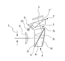
なお、各実施例の構成パラメータは後に示すことにする。各実施例においては、例えば図1に示すように、軸上主光線2を、射出瞳1(又は明るさ絞り14)の中心(観察者眼球の旋回中心位置)から第1プリズム3、第2プリズム4、画像表示素子として設けられたLCD5(又は撮像素子13)の中心に至る光線で定義する。そして、軸上主光線2が第1プリズム3の射出瞳側の面と交差するまでの直線によって定義される光軸をZ軸とし、このZ軸と直交し、かつ、プリズムを構成する各面の偏心面内の軸をY軸と定義し、前記光軸と直交し、かつ、前記Y軸と直交する軸をX軸と定義する。また、射出瞳1(又は明るさ絞り14)の中心をこの座標系の原点とする。そして、軸上主光線2が射出瞳1(又は明るさ絞り14)からLCD5(又は撮像素子13)に至る方向をZ軸の正方向、LCD5(又は撮像素子13)に向かうY軸の方向をY軸の正方向、Y軸とZ軸と右手系を構成するX軸の方向をX軸の正方向とそれぞれ定義する。
【0063】
各実施例では、第1プリズムおよび第2プリズムはこのY−Z平面内で偏心を行なっており、また、第1プリズムおよび第2プリズムに設けられる各回転非対称自由曲面の唯一の対称面をY−Z面としている。
【0064】
偏心面については、対応する座標系の原点から、その面の面頂位置の偏心量(X軸方向、Y軸方向、Z軸方向をそれぞれ、X,Y,Z)と、その面の中心軸(自由曲面については、上記式(4)のZ軸)のX軸,Y軸,Z軸のそれぞれを中心とする傾き角(それぞれα,β,γ(°))とが与えられている。なお、その場合、αとβの正はそれぞれの軸の正方向に対して反時計回りを、γの正はZ軸の正方向に対して時計回りを意味する。その他、球面の曲率半径、面間隔、媒質の屈折率、アッベ数は慣用法によって与えるものとする。
【0065】
また、本発明で用いられる自由曲面の面の形状は上記(4)式により定義し、その定義式のZ軸が自由曲面の軸となる。
【0066】
また、自由曲面の他の定義式として、Zernike多項式がある。この面の形状は次式(12)により定義する。その定義式(12)のZ軸がZernike多項式の軸となる。回転非対称面の定義は、X−Y面に対するZ軸の高さの極座標で定義され、RはX−Y面内のZ軸からの距離、AはZ軸周りの方位角でY軸から測った回転角で表わされる。
【0067】
【0068】
また、回転非対称面な自由曲面の形状は次の式(13)により定義することもできる。その定義式(13)のZ軸が回転非対称面の軸となる。
Z=ΣnΣmCnmXnYn-m ……(13)
ただし、ΣnはΣのnが0〜k、ΣmはΣのmが0〜nを表わす。
【0069】
また、面対称自由曲面(対称面を1つのみ有する回転非対称面)を、この回転非対称面を表わす式(14)により定義する場合は、その対称面により生ずる対称性をX方向に求める場合は、Xの奇数次項を0に(例えばX奇数次項の係数を0にする)、その対称面により生ずる対称性をY方向に求める場合は、Yの奇数次項を0に(例えば、Y奇数次項の係数を0にする)すればよい。
【0070】
また、回転対称非球面の形状は次式(14)により定義する。その定義式(14)のZ軸が回転対称非球面の軸となる。
【0071】
なお、本発明の実施例では、上記(4)式を用いた自由曲面で面形状が表現されているが、上記(12)式、(13)式を用いても同様の作用効果が得られるのは言うまでもない。
【0072】
【実施例】
実施例1、2では、観察光学系として説明する。画像表示素子としては、大きさが0.47インチタイプの縦横9.6mm×7.2mmで、中心視度が−1.0DのLCDを使用している。また、観察画角は、水平半画角12.5°、垂直半画角9.44°であり、瞳径は、Φ4.0mmである。
本発明の実施例1、2に係る観察光学系の光軸を含むY−Z断面図を図1、4に夫々示す。実施例1、2の観察光学系はいずれも、像面と瞳面との間に配置されている。像面側には、観察者が観察する画像を表示する画像表示素子としてLCD5が配置されている。また、第1プリズム3と、第2プリズム4と、第1プリズム3と第2プリズム4との間に挟まれ且つ両プリズムに貼り合わされたホログラフィック素子として体積型ホログラム(HOE)6とを有していて、LCD5に表示された観察像を観察するために瞳面に射出瞳1を形成するようになっている。
なお、各実施例の説明において、光学系の面番号は原則として射出瞳1からLCD5に至る順番で追跡(逆光線追跡)し、第1および第2プリズムにおける各面の順番も逆光線追跡に合わせて表すこととする。また、光学系を介して射出瞳1とLCD5とを結ぶ光路内を進む光束を第1光束ということとする。
【0073】
第1プリズム3は、第1−1面31〜第1−3面33を有している。第1−1面31は、瞳側に配置され、第1光束が全反射臨界角を超えた入射角度で入射したときにはその光束を全反射し、第1光束が全反射臨界角よりも小さい入射角度で入射したときにはその光束を透過させる全反射面で構成されていて、第1光束を透過させる作用と反射する作用とを兼ね備えた、第2の射出面及び第2の反射面として構成されている。
【0074】
第1−2面32は、第1−1面31を境に瞳とは反対側に配置されており、体積型ホログラム6を挟んで第2プリズム4と接合している。第1−2面32の面上には体積型ホログラム6が貼り付けられていて、第1光束が第1の入射角度で入射したときには体積型ホログラム6によりその光束を回折反射し、第1光束が第2の入射角度及び第3の入射角度で入射したときには体積型ホログラム6によりその光束を透過させるように構成されており、第1−2面32は、第1光束を透過させる作用と反射する作用とを兼ね備えた、第1の反射面、第1の射出面及び第2の入射面として構成されている。第1−3面33は、像面側に配置されていて、第1光束を透過させる作用を有する、第1の入射面として構成されている。
【0075】
第2プリズム4は、第2−1面41、第2−2面42を有している。第2−1面41は、第1プリズム3の第1−2面32と対向位置に配置され、体積型ホログラム6を挟んで第1プリズム3の第1−2面32と接合している。第2−1面41の面上には第1プリズム3の第1−2面32に貼り付けられた体積型ホログラム6が貼り付けられていて、第1光束が第2の入射角度及び第3の入射角度で入射したときには体積型ホログラム6によりその光束を透過させるように構成されており、第2−1面41は、第1光束を少なくとも2回透過させる作用を有する、入射面及び射出面として構成されている。
第2−2面42は、第2−1面41を境に瞳とは反対側に配置されていて、第1光束を反射する作用を有する、反射面として構成されている。
また、第1プリズムの第1−2面32と第2プリズムの第2−1面4 1 とは面形状が同一に形成されている。
【0076】
体積型ホログラム6は、上述のように、第1光束が第1の入射角度で入射したときにはその光束を回折反射し、第1光束が第2の入射角度及び第3の入射角度で入射したときには、いずれもその光束を透過させるように形成することによって、第1プリズム3の第1−2面32が第1光束を反射する作用と透過させる作用とを兼ね備えると共に、第2プリズムの第2−1面41が第1光束を少なくとも2回透過させる作用を有するように構成されている。
【0077】
そして、各実施例の観察光学系では、LCD5から射出された第1光束は、第1−3面33を透過して第1プリズム3の内部に入射した後、第1−2面32に貼り付けられた体積型ホログラム6に対し第1の入射角度で入射して体積型ホログラム6により回折反射され、第1−1面31に対し全反射臨界角を超えた入射角度で入射して第1−1面31で全反射され、第1−2面32に貼り付けられた体積型ホログラム6に対し第2の入射角度で入射して体積型ホログラム6を透過して、第1プリズム3から一旦射出される。その後、第1光束は、第2プリズム4の第2−1面41を透過して第2プリズム4の内部に入射し、第2−2面42で反射され、第2−1面21に貼り付けられた体積型ホログラム6に対し第3の入射角度で入射して体積型ホログラム6を透過することによって第2プリズム4から射出される。その後、第1光束は、第1プリズム3の第1−2面32を透過して第1プリズム3の内部に入射し、第1−1面31に対し全反射臨界角よりも小さい入射角度で入射して第1−1面31を透過することによって第1プリズムを射出して射出瞳1側に導かれる。
【0078】
なお、本発明の実施例においては、観察光学系として説明することとするが、観察光学系の像面にLCD5に換えて撮像素子13を配置し、瞳面(射出瞳1の位置)に物体からの光束の明るさを絞る明るさ絞り14を配置することにより、撮像光学系として構成することができる。
その場合には、明るさ絞り14を通過した物体光が、少なくとも、第1プリズム3の第1−1面31に対し全反射臨界角よりも小さい入射角度で入射し第1−1面31を透過して第1プリズム3の内部に入射した後、第1−2面32に貼り付けられた体積型ホログラム6に対し第3の入射角度で入射して体積型ホログラム6を透過して第1プリズム3から一旦射出され、第2プリズム4の第2−1面41を透過して第2プリズム4の内部に入射し、第2−2面42で反射され、第2−1面41に貼り付けられた体積型ホログラム6に対し第2の入射角度で入射して体積型ホログラム6を透過することによって第2プリズム4から射出され、第1プリズム3の第1−2面32を透過して再度第1プリズム3の内部に入射し、第1−1面31に対し全反射臨界角を超えた入射角度で入射して第1−1面31で全反射され、第1−2面32に貼り付けられた体積型ホログラム6に対し第1の入射角度で入射して体積型ホログラム6により回折反射され、第1−3面33を透過することによって第1プリズム3を射出して撮像素子13に導かれるようにする。
その他、各実施例では、体積型ホログラムは、R,G,Bの3層を貼り合わせて構成されており、カラー像を観察することができるようになっている。
【0079】
第1実施例
第1実施例の光学系は、図1に示すように、第1プリズム3のLCD5側の面(第1−3面)33が自由曲面に、体積型ホログラム6が貼り付けられた面(第1−2面)32が平面に、瞳側の面(第1−1面)31が自由曲面に、第2プリズム4の体積型ホログラム6が貼り付けられた面(第2−1面)41が平面に、反射面(第2−2面)42が自由曲面にそれぞれ形成されている。
【0080】
次に、第1実施例の数値データを示す。数値データ中、“FFS”は自由曲面を示している。なお、FFSは第2実施例においても同じく自由曲面を示している。
また、本実施例の像歪みを表す収差図を図2に、横収差を表す収差図を図3にそれぞれ示す。図2中、縦軸はX方向の像高、横軸はY方向の像高を示している。また、図3中、夫々(a)はX方向画角がゼロ、Y方向画角がゼロを通る主光線のY方向の横収差、(b)はX方向画角がゼロ、Y方向画角がゼロを通る主光線のX方向の横収差、(c)はX方向画角がゼロ、Y負方向最大画角を通る主光線のY方向の横収差、(d)はX方向画角がゼロ、Y負方向最大画角を通る主光線のX方向の横収差、(e)はX正方向最大画角、Y負方向最大画角を通る主光線のY方向の横収差、(f)はX正方向最大画角、Y負方向最大画角を通る主光線のX方向の横収差、(g)はX正方向最大画角、Y方向画角がゼロを通る主光線のY方向の横収差、(h)はX正方向最大画角、Y方向画角がゼロを通る主光線のX方向の横収差、(i)はX正方向最大画角、Y正方向最大画角を通る主光線のY方向の横収差、(j)はX正方向最大画角、Y正方向最大画角を通る主光線のX方向の横収差、(k)はX方向画角がゼロ、Y正方向最大画角を通る主光線のY方向の横収差、(l)はX方向画角がゼロ、Y正方向最大画角を通る主光線のX方向の横収差を示している。
【0081】
条件式
条件式(1),(2),(3) |θ|= 68.57°
【0086】
第2実施例
第2実施例の光学系は、図4に示すように、第1プリズム3のLCD5側の面(第1−3面)33が自由曲面に、体積型ホログラム6が貼り付けられた面(第1−2面)32が平面に、瞳側の面(第1−1面)31が回転対称な非球面に、第2プリズム4の体積型ホログラム6が貼り付けられた面(第2−1面)41が平面に、反射面(第2−2面)42が自由曲面にそれぞれ形成されている。
【0087】
次に、第2実施例の数値データを示す。
条件式
条件式(1),(2),(3) |θ|= 69.03°
【0093】
第3実施例
本発明の光学系の第3実施例を図5に示す。図5は、第3実施例にかかる観察光学系の光軸を含むY−Z断面図である。
本実施例の光学系は、第1、第2実施例の光学系の構成に、偏光ビームスプリッタ7、正レンズ8などの光学部材を加えて構成されている。
【0094】
偏光ビームスプリッタ7は、第1プリズム部材3の第1−3面33とLCD5との間に配置されている。偏光ビームスプリッタ7の側方には、偏光板9、照明用光源(LED)10が設けられている。
そして、LED10より射出された照明光は、偏光板9を介して直線偏光成分の光に変換されて偏光ビームスプリッタ7に入射し、そのうちの所定の直線偏光成分の光が偏光ビームスプリッタ7の偏光面7’で反射されてLCD5側の面から射出して、LCD5を照射する。その後、LCD5で反射されることによって直線偏光成分が偏光されて、偏光ビームスプリッタ7に入射し、偏光面7’を透過して偏光ビームスプリッタ7から射出して第1プリズム3の第1−3面33に入射する。
【0095】
また、本実施例では、第1プリズム3のLCD5側の面(第1−3面)33が自由曲面に、体積型ホログラム6が貼り付けられた面(第1−2面)32が平面に、瞳側の面(第1−1面)31が自由曲面又は回転対称非球面に、第2プリズム4の体積型ホログラム6が貼り付けられた面(第2−1面)41が平面に、反射面(第2−2面)42が自由曲面にそれぞれ形成されている。また、反射面(第2−2面)42には、ミラーコーティングが施されている。
正レンズ8は、第1プリズム3の第1−1面31と射出瞳1との間に配置されており、第1プリズム3の第1−1面31から射出された光像の収差を補正して射出瞳1に結像するようになっている。
【0096】
第4実施例
本発明の光学系の第4実施例を図6に示す。図6は、第4実施例にかかる観察光学系の光軸を含むY−Z断面図である。
本実施例の光学系は、第1プリズム3が、第1−3面33と第1−2面32との間の光路中においてプリズム内の第1光束を反射する面34を配置して構成されている。
また、平行平板などのガラスでできたカバー部材11が、第1プリズム3の第1−1面31と射出瞳1との間に配置されている。
【0097】
なお、本実施例では、第1プリズム3のLCD5側の面(第1−3面)33が自由曲面に、体積型ホログラム6が貼り付けられた面(第1−2面)32が平面に、瞳側の面(第1−1面)31が自由曲面又は回転対称非球面に、第1−3面33と第1−2面32との間の光路中においてプリズム内の第1光束を反射する面34が自由曲面に、第2プリズム4の体積型ホログラム6が貼り付けられた面(第2−1面)41が平面に、反射面(第2−2面)42が自由曲面にそれぞれ形成されている。また、反射面(第2−2面)42には、ミラーコーティングが施されている。
【0098】
第5実施例
本発明の光学系の第6実施例を図7に示す。図7は、第6実施例にかかる観察光学系の光軸を含むY−Z断面図である。
本実施例の光学系は、第2プリズム4が、第2−2面42と第2−1面41との間の光路中においてプリズム内の第1光束を反射する面43を配置して構成されている。
【0099】
また、本実施例では、第1プリズム3のLCD5側の面(第1−3面)33が自由曲面に、体積型ホログラム6が貼り付けられた面(第1−2面)32が平面に、瞳側の面(第1−1面)31が自由曲面又は回転対称非球面に、第2プリズム4の体積型ホログラム6が貼り付けられた面(第2−1面)41が平面に、反射面(第2−2面)42が自由曲面に、第2−2面42と第2−1面41との間の光路中においてプリズム内の第1光束を反射する面43が自由曲面に、それぞれ形成されている。
また、負レンズ12が、第1プリズム3の第1−1面31と射出瞳1との間に配置されている。
【0100】
第6実施例
本発明の光学系の第6実施例を図8に示す。図8は、第6実施例にかかる観察光学系の光軸を含むY−Z断面図である。
本実施例の観察光学系は、瞳面から、第1プリズム3を通り抜けて第2プリズム3へと向かう光束を第2光束としたときに、上記各実施例の第2プリズム4の第2面42が、第2光束が全反射臨界角を超えた入射角度で入射したときにはその光束を反射し、第2光束が全反射臨界角よりも小さい入射角度で入射したときにはその光束を透過させる全反射面で構成されている。また、第2プリズム4の第2面42側にはプリズム16が設けられており、LCD5からの観察像のほかに、外部の像を透過観察することができるようになっている。
なお、第2プリズム4の第2面42は、上記のような全反射面とする代わりにハーフミラー面で構成してもよい。
【0101】
第7実施例
本発明の光学系の第7実施例を図9に示す。図9は第7実施例にかかる撮像光学系の光軸を含むY−Z要部断面図である。
本実施例の撮像光学系は、上記第1〜第6実施例の構成においてLCD5を撮像素子13に、射出瞳1を明るさ絞り14に置き換えて構成され、さらに、第2プリズム4が内部の媒質を液体とし、第2プリズム4の反射面(第2−2面)42がデフォーマブルミラー面(形状可変ミラー)(参考文献:Gleb Vdovin, "Quick focusing of imaging optics using micromachined adaptive mirrors", Optics Communications,140,187-190(1997))として構成されている。
【0102】
即ち、第2プリズム4は、プラスチック等で透明かつ中空状に形成され、その内部に液体が充填されて構成されており、液体のバッファーを備えたバッファー部17を備えている。また、第2プリズム4は、デフォーマブルミラー面42の側方に蛇腹状に形状可変に形成された蛇腹部18を備えてており、内部に充填されたバッファーの液圧によって蛇腹部18が伸張又は収縮するようになっている。
【0103】
本実施例によれば、バッファー部17を押圧して、第2プリズム4に液圧を加えることで、蛇腹部18が第2−1面4 1 から離れる方向に広がり、デフォーマブルミラー面42の位置が変化する。デフォーマブルミラー面42の位置が変化すると、その面で反射されて撮像素子13に向かう光束の光路長が変化すると共に、結像位置が変化する。
したがって、本実施例によれば、第2プリズム4を撮像光学系のフォーカシング機構として用いることができる。
【0104】
次に、以上のような本発明による観察光学系、撮像光学系は、物体像を接眼レンズを通して観察する観察装置や、物体像を形成しその像をCCDや銀塩フィルムといった撮像素子に受光させて撮影を行なう撮影装置として用いることが可能である。具体的には、顕微鏡、頭部装着型画像表示装置、内視鏡、プロジェクター、銀塩カメラ、デジタルカメラ、VTRカメラ等がある。以下にその実施形態を例示する。
【0105】
その一例として、図10に頭部装着型で両眼装着用の画像表示装置を観察者の頭部に装着した状態を、図11にその断面図を示す。この構成は、本発明による観察光学系を図12に示すように画像表示素子5を備えた接眼光学系100として用いており、この接眼光学系100を左右一対用意し、それらを眼幅距離だけ離して支持することにより、両眼で観察できる据え付け型又は頭部装着型画像表示装置のようなポータブル型の画像表示装置102として構成されている。
【0106】
すなわち、画像表示装置本体102には、上記のような観察光学系が接眼光学系100として用いられ、その接眼光学系100が左右一対備えられ、それらに対応して像面に液晶表示素子からなる画像表示素子5が配置されている。そして、画像表示装置本体102には、図10に示すように、左右に連続して図示のような側頭フレーム103が設けられ、画像表示装置本体102を観察者の眼前に保持できるようになっている。なお、図11に示すように、接眼光学系100の射出瞳と第1−1面31との間にカバー部材91が配置されている。このカバー部材91としては、平行平面板、正レンズあるいは負レンズの何れを用いてもよい。
【0107】
また、側頭フレーム103にはスピーカ104が付設されており、画像観察と共に立体音響を聞くことができるようになっている。このようにスピーカ104を有する表示装置本体102には、映像音声伝達コード105を介してポータブルビデオカセット等の再生装置106が接続されており、観察者はこの再生装置106を図示のようにベルト箇所等の任意の位置に保持して、映像音響を楽しむことができるようになっている。図10の符号107は再生装置106のスイッチ、ボリューム等の調節部である。なお、画像表示装置本体102の内部には映像処理、音声処理回路等の電子部品を内蔵させてある。
【0108】
なお、コード105は先端をジャックにして、既存のビデオデッキ等に取り付け可能としてもよい。さらに、TV電波受信用チューナーに接続してTV鑑賞用としてもよいし、コンピュータに接続してコンピュータグラフィックスの映像や、コンピュータからのメッセージ映像等を受信するようにしてもよい。また、邪魔なコードを排斥するために、アンテナを接続して外部からの信号を電波によって受信するようにしてもよい。
【0109】
さらに、本発明による観察光学系は、接眼光学系を左右何れか一方の眼前に配置した片眼用の頭部装着型画像表示装置に用いてもよい。図12にその片眼装着用の画像表示装置を観察者の頭部に装着(この場合は、左眼に装着)した状態を示す。この構成では、画像表示素子5を備えた接眼光学系100を1組備えた表示装置本体102が前フレーム108の対応する眼の前方位置に取り付けられ、その前フレーム108には左右に連続して図示のような側頭フレーム103が設けられており、表示装置本体102を観察者の片眼前に保持できるようになっている。その他の構成は図10の場合と同様であり、説明は省く。
【0110】
また、図13〜図15は、本発明による撮像光学系の要部構成を電子カメラのファインダー部の対物光学系に組み込んだ構成の概念図を示す。図13は電子カメラ40の外観を示す前方斜視図、図14は同後方斜視図、図15は電子カメラ40の構成を示す断面図である。
【0111】
電子カメラ40は、この例の場合、撮影用光路42を有する撮影光学系41、ファインダー用光路44を有するファインダー光学系43、シャッター釦45、フラッシュ46、液晶表示モニター47等を含み、カメラ40の上部に配置されたシャッター釦45を押圧すると、それに連動して撮影用対物光学系48を通して撮影が行なわれる。撮影用対物光学系48によって形成された物体像が、ローパスフィルター、赤外カットフィルター等のフィルター51を介してCCD49の撮像面50上に形成される。
【0112】
このCCD49で受光された物体像は、処理手段52を介し、電子画像としてカメラ背面に設けられた液晶表示モニター47に表示される。また、この処理手段52には記録素子61が配置され、撮影された電子画像を記録することもできる。なお、この記録素子61は処理手段52と別体に設けられてもよいし、フロッピーディスク等により電子的に記録書込を行なうように構成してもよい。また、CCD49に代わって銀塩フィルムを配置した銀塩カメラとして構成してもよい。
【0113】
さらに、ファインダー用光路44上には、ファインダー用対物光学系53が配置されており、このファインダー用対物光学系53は、カバーレンズ54と、フォーカシングのために光軸方向に位置調節可能な正レンズ群57と、図6の実施例に示すような明るさ絞り1と第1プリズム3と第2プリズム4とを備えてなる。また、カバー部材として用いられているカバーレンズ54は、負のパワーを有するレンズ群であり、画角を拡大している。このファインダー用対物光学系53によって結像面90上に形成された物体像は、像正立部材であるポロプリズム55の視野枠上に形成される。
【0114】
なお、その視野枠は、ポロプリズム55の第1反射面561と第2反射面562との間を分離し、その間に配置されている。なお、ポロプリズム55は第1反射面561から第4反射面564でなる。このポロプリズム55の後方には、正立正像にされた像を観察者眼球Eに導く接眼光学系59が配置されている。
【0115】
このように構成されたカメラ40は、ファインダー用対物光学系53を少ない光学部材で構成でき、高性能・低コスト化が実現できると共に、対物光学系53の光路自体を折り曲げて構成できるため、カメラ内部での配置の自由度が増し、設計上有利となる。
【0116】
なお、図15の構成において、撮影用対物光学系48の構成については言及しなかったが、撮影用対物光学系48としては屈折型同軸光学系の他に、本発明の2つのプリズム3,4からなる何れかのタイプの撮像光学系を用いることも当然可能である。
【0117】
次に、図16は本発明の撮像光学系を電子カメラ40の撮影部の対物光学系48に、本発明の観察光学系を電子カメラ40の接眼光学系59に組み込んだ構成の概念図を示す。この例の場合は、撮影用光路42上に配置された撮影用対物光学系48は、正レンズからなるカバー部材65と本発明の実施例1、2に示すような2つのプリズム3,4からなる何れかのタイプの撮像光学系からなる。そして、その第1プリズム3とCCD49との間にローパスフィルター、赤外カットフィルター等のフィルター51が配置されており、この撮影用対物光学系48により形成された物体像はCCD49の撮像面50上に形成される。このCCD49で受光された物体像は、処理手段52を介し、液晶表示素子(LCD)60上に電子像として表示される。また、この処理手段52は、CCD49で撮影された物体像を電子情報として記録する記録手段61の制御も行なう。LCD60に表示された画像は、接眼光学系59を介して観察者眼球Eに導かれる。
【0118】
この接眼光学系59は、本発明の実施例1、2に示すような観察光学系と同様の形態を持つ偏心プリズム光学系3,4とその射出瞳側に配置されたカバーレンズ91とからなる。また、LCD60の背後にはそれを照明するバックライト92が配置されている。なお、この撮影用対物光学系48は他のレンズ(正レンズ、負レンズ)を2つのプリズム3,4の物体側あるいは像側にその構成要素として含んでいてもよい。
【0119】
このように構成されたカメラ40は、撮影用対物光学系48、接眼光学系59を少ない光学部材で構成でき、高性能・低コスト化が実現できると共に、光学系全体を同一平面上に並べて配置できるため、この配置平面と垂直方向の厚みの薄型化が実現できる。
【0120】
なお、本例では、撮影用対物光学系48のカバー部材65として、正レンズを配置しているが、負レンズあるいは平行平面板を用いてもよい。
【0121】
ここで、カバー部材を設けずに、本発明の撮像光学系の最も物体側に配置された面をカバー部材と兼用することもできる。本例では、その最も物体側の面は第1プリズム3の入射面31となる。しかし、この入射面31が光軸に対して偏心配置されているため、この面がカメラ前面に配置されてしまうと、被写体側から見た場合、カメラ40の撮影中心が自分からずれているように錯覚してしまい(一般的なカメラ同様、入射面の垂直方向を撮影していると感じるのが通常である。)、違和感を与えてしまう。そこで、本例のように、結像光学系の最も物体側の面が偏心面である場合には、カバー部材65(又は、カバーレンズ54)を設けることが、被写体側から見た場合に違和感を感じずに、既存のカメラと同じ感覚で撮影を受けることができ望ましい。
なお、プリズム3の入射面31にはホログラフィック素子が設けられているため、水分の侵入による回折のピーク波長の変化を防止するためにも、カバー部材65、カバーレンズ91は設けることが望ましい。
【0122】
次に、図17は、本発明による撮像光学系を電子内視鏡の観察系の対物光学系82に、本発明による観察光学系を電子内視鏡の観察系の接眼光学系87に組み込んだ構成の概念図を示す。この例の場合、観察系の対物光学系82、接眼光学系87は実施例1、2と略同様の形態の光学系を用いている。この電子内視鏡は、図17(a)に示すように、電子内視鏡71と、照明光を供給する光源装置72と、その電子内視鏡71に対応する信号処理を行なうビデオプロセッサ73と、このビデオプロセッサ73から出力される映像信号を表示するモニター74と、このビデオプロセッサ73と接続され映像信号等に記録するVTRデッキ75及びビデオディスク76と、映像信号を映像としてプリントアウトするビデオプリンタ77と、例えば図10に示したような頭部装着型画像表示装置(HMD)78と共に構成されており、電子内視鏡71の挿入部79の先端部80と、その接眼部81は、図17(b)に示すように構成されている。
【0123】
光源装置72から照明された光束は、ライトガイドファイバー束88を通って照明用対物光学系89により、観察部位を照明する。そして、この観察部位からの光が、カバー部材85を介して、観察用対物光学系82によって物体像として形成される。この物体像は、ローパスフィルター、赤外カットフィルター等のフィルター83を介してCCD84の撮像面上に形成される。さらに、この物体像は、CCD84によって映像信号に変換され、その映像信号は、図17(a)に示すビデオプロセッサ73により、モニター74上に直接表示されると共に、VTRデッキ75、ビデオディスク76中に記録され、また、ビデオプリンタ77から映像としてプリントアウトされる。また、HMD78の画像表示素子5(図11)に表示されHMD78の装着者に表示される。同時に、CCD84によって変換された映像信号は画像信号導伝手段93を介して接眼部81の液晶表示素子(LCD)86上に電子像として表示され、その表示像は本発明の観察光学系からなる接眼光学系87を経て観察者眼球Eに導かれる。
【0124】
このように構成された内視鏡は、少ない光学部材で構成でき、高性能・低コスト化が実現できると共に、対物光学系80が内視鏡の長軸方向に並ぶため、細径化を阻害することなく上記効果を得ることができる。
【0125】
次に、本発明による光学系を構成するプリズムに体積型ホログラムのような回折素子を設けるときの望ましい構成を図18に示す。図中、偏心プリズムPは、本発明の観察光学系又は撮像光学系中に含まれる第1プリズム3である。いま、回折素子の面Cが、図のように四角形を形成するとき、偏心プリズムPの第1−1面が面対称自由曲面に形成された場合その対称面Dが、この回折素子6の面Cの四角形を形成する辺の少なくとも1つと平行になるように配置することが、美しい像形成の上で望ましい。
【0126】
さらに、この回折素子6の面Cが正方形や長方形といった4つの内角がそれぞれ略90°にて形成されている場合には、面対称自由曲面の対称面Dは、回折素子6の面Cの互いに平行関係にある2辺に対して平行に配置され、この対称面Dが回折素子6の面Cを左右又は上下対称にさせる位置に一致するように構成することが好ましい。このように構成すれば、装置に組み込むときの組み込み精度が出しやすく、量産性に効果的である。
【0127】
さらに、偏心プリズムPを構成する光学面である第1−1面、第1−2面、第1−3面等の内、複数の面又は全ての面が面対称自由曲面の場合には、複数の面又は全ての面の対称面が同一面Dの上に配置されるように構成することが、設計上も、収差性能上も望ましい。そして、この対称面Dと回折素子6のパワーの面との関係は、上述と同様の関係にあることが望ましい。
【0128】
以上説明したように、本発明の光学系は、特許請求の範囲に記載された特徴のほかに下記に示すような特徴も備えている。
【0129】
(1)請求項2に記載の観察光学系において、前記第1プリズムの前記第1−3面と前記画像表示素子との間に、光学部材を配置したことを特徴とする観察光学系。
【0130】
(2)請求項2に記載の観察光学系において、前記第1プリズムの前記第1−1面と前記射出瞳との間に、光学部材を配置したことを特徴とする観察光学系。
【0131】
(3)請求項2に記載の観察光学系において、前記第1プリズムが、前記第1−3面から前記第1−2面に至るまでの光路中に、前記第1光束を反射して前記第1−2面へと導く反射面を有していることを特徴とする観察光学系。
【0132】
(4)請求項2に記載の観察光学系において、前記第2プリズムが、前記第2−1面から前記第2−2面に至るまでの光路中に、前記第1光束を反射して前記第2−2面へと導く反射面を有していることを特徴とする観察光学系。
【0133】
(5)請求項2に記載の観察光学系において、前記第1プリズムの前記第1−2面と前記第2プリズムの前記第2−1面とが、共にプリズム面形状を平面に形成され、その平面上にホログラフィック素子を貼りつけて構成されていることを特徴とする観察光学系。
【0134】
(6)請求項2に記載の観察光学系において、前記第1プリズムの前記第1−1面と前記第2プリズムの前記第2−1面とが、共にプリズム面形状を曲面に形成され、その曲面上にホログラフィック素子を貼りつけて構成されていることを特徴とする観察光学系。
【0135】
(7)上記(5)又は(6)に記載の観察光学系において、前記第1プリズムと前記第2プリズムとの間に貼りつけられたホログラフィック素子が、体積型ホログラムで構成されていることを特徴とする観察光学系。
【0136】
(8)請求項1,2、上記(1)〜(7)に記載の観察光学系において、前記第1プリズムの前記第1−1面の面形状が自由曲面形状で構成されていることを特徴とする観察光学系。
【0137】
(9)請求項1,2、上記(1)〜(7)に記載の観察光学系において、前記第1プリズムの前記第1−1面の面形状が回転対称非球面形状で構成されていることを特徴とする観察光学系。
【0138】
(10)請求項2、上記(1)〜(9)のいずれかに記載の観察光学系において、前記瞳面の中心と前記像面の中心とを結ぶ光線を軸上主光線とし、前記射出瞳を通過する位置での前記軸上主光線の直線を延長した線を視軸とし、前記像面に配置された画像表示素子の表示した画像面からの垂線と前記視軸とのなす角度をθとしたとき、次の条件式(1)を満足するように前記画像表示素子が配置されていることを特徴とする観察光学系。
40.0(°)<|θ|<100.0(°) ……(1)
【0139】
(11)上記(10)に記載の観察光学系において、次の条件式(2)を満足するように前記画像表示素子が配置されていることを特徴とする観察光学系。
60.0(°)<|θ|<85.0(°) ……(2)
【0140】
(12)上記(11)に記載の観察光学系において、次の条件式(3)を満足するように前記画像表示素子が配置されていることを特徴とする観察光学系。
65.0(°)<|θ|<73.0(°) ……(3)
【0141】
(13)請求項2、上記(1)〜(12)のいずれかに記載の観察光学系において、前記第2プリズムの前記第2−2面を光束が該第2−2面に対して全反射臨界角を超えた入射角度で入射したときにはその光束を反射し、全反射臨界角を超えない入射角度で入射したときにはその光束を透過させるような全反射面となるように構成したことを特徴とする観察光学系。
【0142】
(14)上記(13)に記載の観察光学系において、前記第2プリズムの前記第2−2面側に光を透過する光学部材が設けられていることを特徴とする観察光学系。
【0143】
(15)前記請求項2、上記(1)〜(14)のいずれかに記載の観察光学系を内蔵した本体部と、前記観察光学系の射出瞳を観察者の眼球位置に保持するように前記本体部を観察者頭部に支持する支持部材と、前記観察者の耳に音声を与えるスピーカー部材とを有していることを特徴とする頭部装着型画像表示装置。
【0144】
(16)上記(15)に記載の頭部装着型画像表示装置において、前記本体部が、右眼用の観察光学系と左眼用の観察光学系とを備え、前記スピーカー部材が、右耳用スピーカー部材と左耳用スピーカー部材とを有するように構成されていることを特徴とする頭部装着型画像表示装置。
【0145】
(17)上記(15)又は(16)に記載の頭部装着型画像表示装置において、前記スピーカー部材がイヤホンで構成されていることを特徴とする頭部装着型画像表示装置。
【0146】
(18)前記請求項3に記載の撮像光学系において、前記第1プリズムの前記第1−3面と前記撮像素子との間に、光学部材を配置したことを特徴とする撮像光学系。
【0147】
(19)前記請求項3に記載の撮像光学系において、前記第1プリズムの前記第1−1面と前記明るさ絞りとの間に、光学部材を配置したことを特徴とする撮像光学系。
【0148】
(20)前記請求項3に記載の撮像光学系において、前記第1プリズムが、前記第1−2面から前記第1−3面に至るまでの光路中に、前記第1光束を反射して前記第1−3面へと導く反射面を有していることを特徴とする撮像光学系。
【0149】
(21)前記請求項3に記載の撮像光学系において、前記第2プリズムが、前記第2−2面から前記第2−1面に至るまでの光路中に、前記第1光束を反射して前記第2−2面へと導く反射面を有していることを特徴とする撮像光学系。
【0150】
(22)前記請求項3に記載の撮像光学系において、前記第1プリズムの前記第1−2面と前記第2プリズムの前記第2−1面とが、共にプリズム面形状を平面に形成され、その平面上にホログラフィック素子を貼りつけて構成されていることを特徴とする撮像光学系。
【0151】
(23)前記請求項3に記載の撮像光学系において、前記第1プリズムの前記第1−2面と前記第2プリズムの前記第2−1面とが、共にプリズム面形状を曲面に形成され、その曲面上にホログラフィック素子を貼りつけて構成されていることを特徴とする撮像光学系。
【0152】
(24)上記(22)又は(23)に記載の撮像光学系において、前記第1プリズムと前記第2プリズムとの間に貼りつけられたホログラフィック素子が、体積型ホログラムで構成されていることを特徴とする撮像光学系。
【0153】
(25)請求項1,3、上記(18)〜(24)に記載の撮像光学系において、前記第1プリズムの前記第1−1面の面形状が、自由曲面形状で構成されていることを特徴とする撮像光学系。
【0154】
(26)請求項1,3、上記(18)〜(24)に記載の撮像光学系において、前記第1プリズムの前記第1−1面の面形状が、非球面形状で構成されていることを特徴とする撮像光学系。
【0155】
(27)請求項3、上記(18)〜(26)のいずれかに記載の撮像光学系において、前記明るさ絞りの中心と前記像面の中心とを結ぶ光線を軸上主光線とし、前記明るさ絞りを通過する位置での前記軸上主光線の直線を延長した線を視軸とし、前記像面に配置された撮像素子の撮像面からの垂線と前記視軸とのなす角度をθとしたとき、次の条件式(1)を満足するように前記撮像素子が配置されていることを特徴とする撮像光学系。
40.0(°)<|θ|<100(°) ……(1)
【0156】
(28)上記(27)に記載の撮像光学系において、次の条件式(2)を満足するように前記撮像素子が配置されていることを特徴とする撮像光学系。
60.0(°)<|θ|<85.0(°) ……(2)
【0157】
(29)上記(28)に記載の撮像光学系において、次の条件式(3)を満足するように前記撮像素子が配置されていることを特徴とする撮像光学系。
65.0(°)<|θ|<73.0(°) ……(3)
【0158】
(30)請求項1,3、上記(18)〜(29)のいずれかに記載の撮像光学系において、前記第2プリズムの媒質を液体とし、前記第2プリズムの反射面を形状可変ミラーとした、フォーカシング機構を有することを特徴とする撮像光学系。
【0159】
【発明の効果】
以上、本発明によれば、携帯電話や携帯情報端末そして頭部装着型の虚像観察装置に用いるのに適した、小型で、軽量、かつ明るく、さらに高解像度を有する観察光学系、撮像光学系を提供することができる。
【図面の簡単な説明】
【図1】本発明の第1実施例にかかる光学系の光軸を含むY−Z断面図である。
【図2】第1実施例の像歪みを表す収差図である。
【図3】第1実施例の横収差を表す収差図である。
【図4】本発明の第2実施例にかかる光学系の光軸を含むY−Z断面図である。
【図5】本発明の第3実施例にかかる光学系の光軸を含むY−Z断面図である。
【図6】本発明の第4実施例にかかる光学系の光軸を含むY−Z断面図である。
【図7】本発明の第5実施例にかかる光学系の光軸を含むY−Z断面図である。
【図8】本発明の第6実施例にかかる光学系の光軸を含むY−Z断面図である。
【図9】本発明の第7実施例にかかる光学系の光軸を含むY−Z断面図である。
【図10】本発明の観察光学系を用いた頭部装着型で両眼装着用の画像表示装置を観察者の頭部に装着した状態を示す図である。
【図11】図10の断面図である。
【図12】本発明の観察光学系を用いた頭部装着型で片眼装着用の画像表示装置を観察者の頭部に装着した状態を示す図である。
【図13】本発明の撮像光学系及び観察光学系を適用した電子カメラの外観を示す前方斜視図である。
【図14】図13の電子カメラの後方斜視図である。
【図15】図13の電子カメラの1つの構成を示す断面図である。
【図16】本発明の撮像光学系及び観察光学系を適用した別の電子カメラの概念図である。
【図17】本発明の撮像光学系及び観察光学系を適用した電子内視鏡の概念図である。
【図18】本発明による光学系を構成するプリズムにHOEを配置するときの好ましい構成を示す図である。
【図19】光学系の像面と瞳面との間における回折素子の配置と収差補正上の効果との関係を説明するための原理図であり、(a)は回折素子を像面から比較的離れた位置に配置した構成、(b)は回折素子を像面の近くに配置した構成を示している。
【図20】本発明の光学系における視軸と画像表示素子の画像面からの垂線とのなす角を示す説明図である。
【図21】本発明におけるHOEを定義するための原理図である。
【図22】本発明の構成の体積型ホログラム面における回折効率の計算条件を示す説明図である。
【図23】本発明の構成の体積型ホログラム面における波長が520nmの軸上主光線の入射角に対する回折効率を、入射角度±80°の範囲において示すグラフである。
【図24】本発明の構成の体積型ホログラム面における波長が520nmの軸上主光線の入射角に対する回折効率を、入射角度40°〜80°の範囲において示すグラフである。
【図25】本発明の構成の体積型ホログラム面における波長に対する入射角度が58.0°の軸上主光線の回折効率を示すグラフである。
【符号の説明】
1 射出瞳
2 軸上主光線
3 第1プリズム
31 第1−1面
32 第1−2面
33 第1−3面
34 第1−3面と第1−2面との間の光路中においてプリズム内の第1光束を反射する面
4 第2プリズム
41 第2−1面
42 第2−2面
43 第2−2面と第2−1面との間の光路中においてプリズム内の第1光束を反射する面
5 LCD
6 体積型ホログラム
7 偏光ビームスプリッタ
7’ 偏光面
8 正レンズ
9 偏光板
10 照明用光源(LCD)
11 カバー部材
12 負レンズ
13 撮像素子
14 明るさ絞り
15 反射防止コーティング
16 プリズム
17 バッファー部
18 蛇腹部
19 平行平板
40 カメラ
41 撮像光学系
42 撮影用光路
43 ファインダー光学系
44 ファインダー用光路
45 シャッター
46 フラッシュ
47 液晶表示モニター
48 撮影用対物光学系
49 CCD
50 撮像面
51 フィルター
52 処理手段
53 ファインダー用対物光学系
54 負レンズ群
55 ポロプリズム
561〜564 第1〜4反射面
57 正レンズ群
59 接眼光学系
60 液晶表示素子(LCD)
61 記録素子
65 カバー部材
71 電子内視鏡
72 光源装置
73 ビデオプロセッサ
74 モニター
75 VTRデッキ
76 ビデオディスク
77 ビデオプリンタ
78 頭部装着型画像表示装置(HMD)
79 挿入部
80 先端部
81 接眼部
82 観察用対物光学系
83 フィルター
84 CCD
85 カバー部材
86 液晶表示素子(LCD)
87 接眼光学系
88 ライトガイドファイバー束
89 照明用対物光学系
90 結像面
91 カバー部材
92 バックライト
93 画像信号導伝手段
100 接眼光学系
102 画像表示装置(本体)
103 側頭フレーム
104 スピーカ
105 映像音声伝達コード
106 再生装置
107 調節部
108 前フレーム
P 偏心プリズム
C 回折素子の面
D 面対称自由曲面の対称面[0001]
BACKGROUND OF THE INVENTION
The present invention relates to an observation optical system and an imaging optical system, and in particular, an image display device and a camera that can be held on the observer's head or face and can be added to a mobile phone or a portable information terminal. The present invention relates to an optical system used in an imaging apparatus.
[0002]
[Prior art]
2. Description of the Related Art In recent years, for the purpose of allowing an individual to enjoy a large screen image, an image display device, particularly an image display device of a type worn on the head or face, has been actively developed. In recent years, with the widespread use of mobile phones and mobile information terminals, there is an increasing need to view images and character data on mobile phones and mobile information terminals on a large screen.
[0003]
Conventionally, a proposal for displaying an image on the display surface of the image display means using an optical system composed of all three rotationally asymmetric transmission surfaces and reflection surfaces and allowing the observer to visually recognize the image is disclosed. No. 234137, JP-A-9-197336, and JP-A-9-197337. Also, US Pat. No. 5,959,781 proposes that the image on the display surface of the image display means displays a magnified virtual image by directing light to a concave mirror using a total reflection surface or a beam splitter surface, and allowing an observer to visually recognize the image. ing.
[0004]
[Problems to be solved by the invention]
However, in the case of JP-A-8-234137, JP-A-9-197336, and JP-A-9-197337, the prism is composed of a single medium, and therefore has no chromatic aberration correcting means. Since the lateral chromatic aberration and the like are insufficiently corrected, it is difficult to increase the resolution. In the case of JP-A-9-197336 and JP-A-9-197337, the prism is long in the length direction (Y direction). In the case of U.S. Pat. No. 5,959,781, the number of parts is large, so that the assembly is not only difficult due to the high cost, but the prism medium is used in order to utilize the polarization characteristics by using the polarization beam splitter for the beam splitter. It becomes necessary to use a material having extremely low birefringence such as glass, which causes a problem that the weight increases. If the optical system is made of a plastic material in order to avoid this weight problem, the polarizing beam splitter cannot be used as the beam splitter, and a half mirror or the like needs to be used. However, this causes a problem that only a dark image can be observed because the light from the electronic image is attenuated by the half mirror surface before reaching the observer's eye.
[0005]
Therefore, the present invention provides an observation optical system or an imaging optical system that is small enough to be used for a mobile phone, a portable information terminal, and a head-mounted virtual image observation apparatus, is light and bright, and has high resolution. The purpose is to provide.
[0006]
[Means and Actions for Solving the Problems]
An optical system according to the present invention is an optical system disposed between a pupil plane and an image plane, wherein the optical system includes at least a first prism, a second prism, the first prism, and the second prism. A holographic element that is sandwiched between and bonded to both prisms, and the light beam traveling in the optical path connecting the pupil plane and the image plane via the optical system is defined as the first light beam The first prism is arranged on the pupil side and has a function of transmitting and reflecting the first light beam, and a function of reflecting the first surface. Has a first-second surface disposed on the opposite side, and a first-third surface disposed on the image-surface side and transmitting the first light flux, and the second prism is configured to have the first-first surface. Having the same shape as the two surfaces and arranged opposite to each other, the first light flux is at least twice A 2-1 surface to be passed, and a 2-2 surface that is disposed on the opposite side of the pupil from the 2-1 surface of the second prism and reflects the first light flux. The holographic element diffracts and reflects the light beam when the first light beam is incident on the holographic element at the first incident angle, and reflects the light beam when the first light beam is incident at the second and third incident angles. By forming the first prism so as to transmit, the first-second surface of the first prism is configured to have both the function of transmitting the first light beam and the function of reflecting, and the first prism of the first prism. When one surface reflects the light beam when the first light beam is incident on the first-first surface at an incident angle exceeding the critical angle for total reflection, and enters the incident angle not exceeding the critical angle for total reflection. The entire fabric that transmits the luminous flux By configuring such that the surface is characterized by being configured to combine both effects of the reflection and transmission.
[0007]
In the observation optical system including the above optical system, the observation optical system according to the present invention includes an image display element that displays an image to be observed by the observer on the image plane, and the eyeball of the observer is on the pupil plane. An exit pupil is formed so as to be positioned, and the first light beam emitted from the image display element passes through at least the first-3 surface and enters the first prism, and the first-2 surface. Diffracted and reflected by the holographic element by being incident at the first incident angle, totally reflected at the first-first surface, and at the second incident angle with respect to the first-second surface. When incident, the light passes through the holographic element, exits from the first prism, passes through the 2-1 surface, enters the second prism, and is reflected by the 2-2 surface; The third incidence with respect to the 2-1 surface Is incident on the holographic element, exits the second prism, passes through the first-second surface, and enters the first prism again, and passes through the first-first surface. Thus, the first prism is emitted and guided to the exit pupil side.
[0008]
For example, the image observation optical system according to the present invention includes a first prism and a second prism in a virtual image observation apparatus having a positive refractive power as a whole that generates an exit pupil for observing an electronic image displayed on an image display apparatus. The first prism includes a rotationally asymmetric refracting surface, a rotationally symmetric surface or rotationally asymmetric surface having functions of total reflection and transmission on the exit pupil side, and a volume hologram element on a cylindrical substrate or a planar substrate. And an incident surface formed in the same manner as a surface on which a volume hologram element is disposed on a cylindrical substrate or a planar substrate whose surface shape is the first prism, and rotationally symmetric. Or it comprises a rotationally asymmetric reflecting surface.
[0009]
In that case, the first-first surface of the first prism and the second-first surface of the second prism are both configured to have a planar prism shape, and a holographic element is pasted on the plane. The surface of the first prism 1-2 and the surface 2-1 of the second prism are both formed into a curved surface, and the surface of the holographic element is formed on the curved surface. A holographic element is attached and the holographic element is sandwiched between these surfaces. Further, the holographic element to be attached to the first-second surface and the second-first surface is composed of a volume hologram having rotationally asymmetric power.
[0010]
If a volume hologram having rotationally asymmetric power is arranged on the first and second surfaces, the rotationally asymmetric lateral chromatic aberration of the prism generated on a curved surface arranged eccentrically with respect to the optical axis. Therefore, it is possible to display a high-resolution image.
[0011]
In general, it is known that a diffractive optical element having a large diffraction angle is difficult to manufacture because the pitch of the grating structure included in the element becomes fine. However, the volume hologram element according to the present invention is intended for optical path division and lateral chromatic aberration correction, and can be easily manufactured because the reflection diffraction angle is nearly specular and the optical power can be made small. .
[0012]
Although the photosensitive material for volume hologram elements supplied in the form of a flat film is relatively easy to bend into a cylindrical shape, it is not possible to process into a substrate shape having curvature in both the X and Y directions at the same time. Have difficulty.
Therefore, if the volume hologram is arranged on a plane with a prism surface formed in a plane in the present invention as a substrate, a configuration that can be easily produced can be obtained.
[0013]
Further, in the present invention, if a prismatic surface formed in a cylindrical shape is used as a substrate and a volume hologram is used on the cylindrical surface, it is possible to further correct Y direction distortion correction and Y direction component telecentricity. It becomes possible.
[0014]
If a volume hologram having rotationally asymmetric power is arranged on the first-first surface and the second-first surface as in the present invention, the lateral chromatic aberration is corrected at the position where the principal ray of each angle of view is separated. Therefore, it is possible to correct the chromatic aberration of magnification with higher accuracy and ease. This will be described with reference to FIG.
FIG. 19 is a principle diagram for explaining the relationship between the arrangement of the diffractive element between the image plane and the pupil plane of the optical system and the effect on aberration correction. FIG. 19A shows a comparison of the diffractive element from the image plane. FIG. 5B shows a configuration in which the diffractive elements are arranged near the image plane. For easy understanding, in FIG. 19, the prism is replaced with a lens so that the optical path is not bent.
In FIG. 19A, the diffractive element is disposed between the two lenses, and in FIG. 19B, the diffractive element is disposed between the lens and the image plane.
[0015]
Here, in the case of FIG. 19 (a), since the diffractive element is arranged at a position where chief rays at each angle of view are not separated so much, in a region where rays of a plurality of angles of view overlap, the rays at one angle of view. If the diffractive element is configured to have the power to correct the lateral chromatic aberration, the lateral chromatic aberration of light rays at other angles of view will occur. On the other hand, in the case of FIG. 19 (b), the diffractive element is arranged at a position where the chief rays of each angle of view are further separated as compared with FIG. 19 (a). The diffractive element can be configured to have the power to correct the lateral chromatic aberration without overlapping, and the lateral chromatic aberration can be performed with higher accuracy.
[0016]
By the way, it is conceivable to provide an air space between the first prism and the second prism in order to improve the decentration aberration correction capability and to provide a rotationally asymmetric distortion correction and a telecentric optical system. However, in that case, in order to reduce the slide amount of the optical path due to refraction, it is difficult in terms of the mechanical configuration to set while keeping the distance between the first prism and the second prism as narrow as possible.
In that respect, if the first prism and the second prism are joined together with the holographic element sandwiched as in the present invention, it is not necessary to provide an air gap between the prisms. This is unnecessary and is advantageous in terms of mechanism. Moreover, as described above, since the holographic element can be arranged at a position close to the image plane, even if a strong curved surface is provided on the prism surface to correct distortion, the strong lateral chromatic aberration generated from the curved surface is excellent. It can be corrected.
[0017]
Further, according to the present invention, dust can be prevented by sandwiching the holographic element between the first prism and the second prism, so that dust and the like can be prevented from being magnified without a separate dust-proof member. In addition, it is possible to prevent the peak wavelength of diffraction efficiency from changing due to expansion of the holographic element due to moisture intrusion into the holographic element from the outside.
[0018]
Further, in the present invention, the surface that functions as total reflection and refraction of the first prism, for example, the above-mentioned 1-1 surface is a free-form surface in order to make an optical system with excellent rotationally asymmetric distortion correction and telecentricity. These rotationally asymmetric surfaces are desirable, but they can also be composed of rotationally symmetric surfaces such as spherical surfaces, aspheric surfaces, and anamorphic surfaces.
[0019]
In the observation optical system of the present invention, as described above, the light beam incident on the first prism is incident on the volume hologram at the first incident angle to be reflected and diffracted, and then the pupil side surface (first surface). -1 plane) is incident at an incident angle larger than the total reflection critical angle, and is totally reflected by satisfying the total reflection condition. The totally reflected light beam re-enters the volume hologram surface at the second incident angle. However, since it falls outside the range of angle selectivity of the volume hologram, the diffraction efficiency becomes extremely low, and it passes through as it is. Then, it is emitted into the second prism.
[0020]
The light beam that has entered the second prism is refracted and reflected by the incident surface and the reflecting surface, and then re-enters the volume hologram surface at a third incident angle. The incident angle is significantly different from the first incident angle, and is out of the range of the angle selectivity of the volume hologram, so that the diffraction efficiency is extremely low. Led to. The light beam incident on the first prism is incident on the pupil side surface (1-1 surface) at an incident angle not exceeding the total reflection critical angle, is transmitted through the first prism, and is emitted from the first prism. It will be guided to the eyeball.
[0021]
Therefore, in the present invention, if the total reflection surface and the volume hologram element are used so as to selectively use the reflection and transmission of the light beam, there is no need to provide a polarization beam splitter for optical path branching. Since the prism member can be made of a plastic material having a higher birefringence property than that, it is possible to provide a virtual image observation apparatus that is lightweight and has high productivity. In addition, since it is not necessary to provide a half mirror or the like for the purpose of optical path branching, it is possible to provide a bright electronic image with little light loss to the observer.
[0022]
Further, as in the present invention, if the inside of the prism in the same region between the surface having the total reflection and transmission action and the surface having the volume hologram is passed three times, the thickness direction of the optical system Thinning in the (Z direction) and shortening in the length direction (Y direction) can be achieved.
[0023]
In the present invention, a ray connecting the center of the pupil plane and the center of the image plane is used as an axial principal ray, and a straight line of the axial principal ray at a position passing through the exit pupil is extended.lineIs the visual axis,An angle formed by a perpendicular from the image plane displayed by the image display element arranged on the image plane and the visual axis.When θ is θ (see FIG. 20), it is important that the image element display element is arranged so as to satisfy the following conditional expression (1).
40.0 (°) <| θ | <100.0 (°) (1)
[0024]
When θ exceeds the upper limit of the conditional expression (1), the tilt of the total reflection surface increases, the optical system thickness (Z direction) increases, and the decentering amount of the reflection surface of the second prism increases. Therefore, it becomes difficult to correct decentration aberrations.
Further, if θ is reduced beyond the lower limit of the conditional expression (1), it becomes difficult to satisfy the critical angle condition of the total reflection surface.
[0025]
In the present invention, it is more desirable to satisfy the following conditional expression (2).
60.0 (°) <| θ | <85.0 (°) ...... (2)
[0026]
Furthermore, in the present invention, it is more desirable to satisfy the following conditional expression (3).
65.0 (°) <| θ | <73.0 (°) …… (3)
[0027]
In the observation optical system of the present invention, an optical member such as a prism, a parallel plate glass, or a positive or negative lens is provided between the first-third surface of the first prism and the image display element. May be arranged.
[0028]
In the observation optical system of the present invention, an optical member such as a prism, a parallel plate glass, or a positive or negative lens is provided between the first-first surface of the first prism and the exit pupil. You may arrange.
[0029]
In the observation optical system of the present invention, the first prism reflects the first light flux in the optical path from the first-3 surface to the first-2 surface, and the first-2. You may have the reflective surface which leads to a surface.
[0030]
In the observation optical system of the present invention, the second prism reflects the first light flux in the optical path from the 2-1 surface to the 2-2 surface, and the 2-2. You may have the reflective surface which leads to a surface.
[0031]
Note that these configurations of the optical system of the present invention can be applied not only to an observation system but also to an imaging system.
An image pickup optical system according to the present invention is an image pickup optical system including the above optical system, wherein an image pickup element that picks up an object image is disposed on the image plane, and a brightness stop that reduces the brightness of a light beam from the object on the pupil plane The object light having passed through the aperture stop is incident on the first prism through at least the first-first surface, and the third incident on the first-second surface. When incident at an angle, the light passes through the holographic element, exits from the first prism, passes through the 2-1 surface, enters the second prism, and is reflected by the 2-2 surface. Is incident on the second-first surface at the second incident angle, passes through the holographic element, exits the second prism, passes through the first-second surface, and again Incident into the first prism and totally reflected by the 1-1 surface The first holographic element is diffracted and reflected by entering the first-second surface at the first incident angle, and the first prism is emitted by passing through the first-third surface. It is configured to be guided to the image sensor.
That is, in the observation optical system of the present invention, an image display element that displays an image observed by an observer and an exit pupil are arranged. In the imaging optical system of the present invention, an image pickup element that picks up an object image and a light flux from the object Each is replaced with a brightness stop that reduces the brightness.
And also in an imaging optical system, it is preferable to set it as the structure according to observation optical systems, such as the above-mentioned conditional expression.
[0032]
Furthermore, the imaging optical system of the present invention is configured such that the medium of the second prism is liquid and the reflecting surface of the second prism is configured as a deformable mirror (variable shape mirror), so that the second prism can be used as the imaging optical system. It can also be used as a focusing mechanism.
[0033]
In addition, the observation optical system of the present invention reflects the 2-2 surface of the second prism when the light beam is incident on the 2-2 surface at an incident angle exceeding the total reflection critical angle, You may comprise so that it may become a total reflection surface which permeate | transmits when it injects with the incident angle which does not exceed a reflection critical angle. Further, an optical member that transmits light may be provided on the 2-2 surface side.
If configured in this way, see-through observation is possible, and without damaging normal external observation, the head or face-mounted image display device using the observation optical system of the present invention can be continuously worn, The trouble of attaching and detaching the head or face-mounted image display device can be saved.
It is also possible to observe a multiple image obtained by superimposing an external observation image and an image from the image display element.
In order to enable these see-through observations, the optical member provided on the second 2-2 surface side of the second prism is made of a transparent member such as glass or plastic.
In order to enable see-through observation, the second-second surface may be formed of a half mirror.
[0034]
Further, the image display element, a main body portion in which any one of the observation optical systems of the present invention as described above is arranged as an eyepiece optical system, and the exit pupil of the observation optical system are held at the eyeball position of the observer. A head-mounted image display apparatus can be configured by including a support member that supports the main body portion on the observer's head and a speaker member that provides sound to the ears of the observer.
[0035]
In this case, in the head-mounted image display device, the main body portion includes an observation optical system for the right eye and an observation optical system for the left eye, and the speaker member is a right ear speaker member and a left ear You may comprise so that it may have a speaker member.
[0036]
In the head-mounted image display device, the speaker member may be an earphone.
[0037]
In the optical system of the present invention, the observation optical system uses reverse ray tracing, the imaging optical system uses forward ray tracing, passes through the object point center, the observation optical system passes through the pupil, and the imaging optical system passes through the center of the aperture stop. When a light beam reaching the center of the image plane is an axial principal ray, and at least one reflecting surface is not decentered with respect to the axial principal ray, the incident light beam and the reflected light beam of the axial principal ray travel on the same optical path. The axial principal ray is blocked in the optical system. As a result, an image is formed only with a light beam whose central portion is shielded from light, and the center becomes dark or no image is formed at the center. Therefore, an eccentric prism is used as the prism used in the present invention.
[0038]
Further, when the reflecting surface to which power is applied is decentered with respect to the axial principal ray, it is desirable that at least one of the surfaces constituting the prism member used in the present invention is a rotationally asymmetric surface. Among these, it is particularly preferable in terms of aberration correction that at least one reflecting surface of the prism member is a rotationally asymmetric surface.
[0039]
In order to bend the optical path and use the optical path in the common region in an overlapping manner, it is necessary to decenter the optical system. However, if the optical system is a decentered optical system to bend the optical path in this way, decentration aberrations such as rotationally asymmetric distortion and rotationally asymmetric field curvature occur. In order to correct this decentration aberration, a rotationally asymmetric surface is used as described above.
[0040]
For the same reason, it is desirable that the power surface of the holographic element used in the present invention is also a rotationally asymmetric surface.
In addition, the surface shape of the base surface on which the holographic element is provided includes a spherical surface, an aspherical surface, an anamorphic surface, a toric surface, a surface having only one symmetrical surface, a surface, in addition to the planar shape and the cylindrical shape as described above. It may be formed in any shape of a symmetric free-form surface.
[0041]
In addition, the rotationally asymmetric surface used in the present invention can be constituted by an anamorphic surface, a toric surface, and a plane-symmetric free-form surface having only one plane of symmetry. In addition, it is preferable that the free-form surface has only one plane of symmetry.
[0042]
In the present invention, the axial principal ray is traced by the reverse ray tracing in the observation optical system through the exit pupil center and reaching the center of the image display element, and in the imaging optical system, it passes through the center of the aperture stop. The ray reaching the center of the image sensor is defined by forward ray tracing. An optical axis defined by a straight line from the center of the exit pupil or the aperture stop to the exit pupil side surface of the first prism is defined as the Z axis. An axis that is orthogonal and within the eccentric surface of each surface constituting the first prism is defined as the Y axis, and an axis that is orthogonal to the Z axis and orthogonal to the Y axis is defined as the X axis. The center of the exit pupil or the aperture stop is the origin of the coordinate system in the observation optical system or the imaging optical system of the present invention. Further, in the present invention, as described above, surface numbers are assigned by back ray tracing from the exit pupil to the image display element, or forward ray tracing from the brightness stop to the image sensor, and the axial principal ray is The direction from the image display element to the image display element or the direction from the aperture stop to the image sensor is the positive direction of the Z axis, the direction of the Y axis toward the image display element or the direction of the Y axis toward the image sensor is the positive direction of the Y axis, Y The direction of the X axis constituting the axis, the Z axis, and the right-handed system is defined as the positive direction of the X axis.
Here, the free-form surface used in the present invention is defined by the following equation (4). Note that the Z axis of the defining formula is the axis of the free-form surface.
[0043]
However, the first term of the equation (4) is a spherical term, and the second term is a free-form surface term. In the spherical term, C is the curvature of the vertex, k is the conic constant (conical constant), r = √ (X2+ Y2).
[0044]
The free-form surface term can be expanded as in the following equation (5).
However, Cj(J is an integer of 2 or more) is a coefficient.
[0045]
In general, the free-form surface does not have a symmetric surface in both the XZ plane and the YZ plane. However, in the present invention, by setting all odd-order terms of X to 0, This is a free-form surface having only one parallel symmetry plane. Such a free-form surface is, for example, C in the above definition (4).2, CFive, C7, C9, C12, C14, C16, C18, C20, Ctwenty three, Ctwenty five, C27, C29, C31, C33, C35It can be achieved by setting the coefficient of each term of.
[0046]
Further, by setting all odd-numbered terms of Y to 0, a free-form surface having only one symmetry plane parallel to the XZ plane is obtained. Such a free-form surface is, for example, C in the above definition (4).Three, CFive, C8, CTen, C12, C14, C17, C19, Ctwenty one, Ctwenty three, Ctwenty five, C27, C30, C32, C34, C36It can be achieved by setting the coefficient of each term of.
[0047]
Further, any one of the directions of the symmetry plane is set as a symmetry plane, and the eccentricity in the corresponding direction, for example, the eccentric direction of the optical system with respect to the symmetry plane parallel to the YZ plane is in the Y-axis direction, XZ By making the decentration direction of the optical system the X-axis direction with respect to a symmetric plane parallel to the plane, it becomes possible to improve the manufacturability at the same time while effectively correcting the rotationally asymmetric aberration caused by the decentration. .
[0048]
Further, the definition formula (4) is shown as an example as described above, and in the present invention, a rotationally asymmetric aberration caused by decentering by using a rotationally asymmetric surface having only one symmetric surface. However, it is needless to say that the same effect can be obtained for any definition formula other than the above definition formula (4).
[0049]
In the present invention, the shape of the reflecting surface provided on the prism member can be configured as a plane-symmetric free-form surface having only one plane of symmetry.
[0050]
The shape of the anamorphic surface is defined by the following equation (6). A straight line passing through the origin of the surface shape and perpendicular to the optical surface is the axis of the anamorphic surface.
Here, when n = 4 (fourth order term) is considered as an example, the above expression (6) can be expressed by the following expression (7) when expanded.
Rx = 1 / Cx, Ry = 1 / Cy
Are in a relationship.
[0052]
The toric surfaces include an X toric surface and a Y toric surface, which are defined by the following equations (8) and (9), respectively. A straight line passing through the origin of the surface shape and perpendicular to the optical surface is the axis of the toric surface.
The X toric surface is defined by the following equation (8).
Rx = 1 / Cx, Ry = 1 / Cy
Are in a relationship.
[0053]
The holographic element includes a relief hologram and a volume hologram. Relief-type holograms have low incident angle selectivity and wavelength selectivity, and diffract light with a specific incident angle and wavelength to form the required order light. However, diffraction with other incident angles and wavelengths is also diffracted. It has the property that it is diffracted in a state where the efficiency is lowered and forms an image as unnecessary order light. On the other hand, the volume hologram has high incident angle selectivity and wavelength selectivity, and diffracts only light of a specific wavelength and incident angle to form an image as a required order light, and most of the other light is 0th order light. It has a characteristic that it is difficult to form an image of unnecessary order light because it is transmitted.
Therefore, if a reflection type volume hologram is used as the holographic element used in the first prism as in the present invention, the occurrence of image blur due to unnecessary order light can be prevented, and a clear observation image can be obtained.
[0054]
The volume hologram (HOE) which is a holographic element in the present invention is defined as follows. FIG. 21 is a principle diagram for defining the HOE in the present invention.
First, the ray tracing of the wavelength λ incident on the HOE surface and further emitted is performed by the reference wavelength λ.0= Optical path difference function Φ on the HOE plane defined for HWL0Is given by the following equation (10).
ndQd・ N = niQi・ N + m (λ / λ0) ∇Ф0・ N ...... (10)
Where N is the normal vector of the HOE plane and ni(Nd) Is the refractive index on the incident side (exit side), Qi(Qd) Is an incident (emitted) vector (unit vector). M = HOR is the diffraction order of the emitted light.
[0055]
HOE is the
Φ0= Φ0 2P
= N2・ S2・ R2-N1・ S1・ R1
It becomes. Where r1(R2) Is point P1(Point P2) To a predetermined coordinate on the HOE surface (> 0), n1(N2) Is the point P of the medium in which the HOE is placed at the time of manufacture1(Point P2) Is the refractive index of the side where1= HV1, and s2= HV2 is a code considering the traveling direction of light. This code is REA = + 1 when the light source is a divergent light source (real point light source), and VIR = −1 when the light source converges (virtual point light source). As the definition of HOE in the lens data, the refractive index n of the medium in which the HOE is placed at the time of manufacturing (definition)1(N2) Is the point P of the medium in contact with the HOE surface in the lens data.1(Point P2) Is the refractive index on the side on which.
[0056]
In a general case, the reference light and the object light when manufacturing the HOE are not necessarily spherical waves.
HOE optical path difference function Φ in this case0Is an additional phase term Φ expressed as a polynomial0 Poly(Reference wavelength λ0The optical path difference function in (5) can be added and expressed by the following equation (11).
Φ0= Φ0 2P+ Φ0 Poly ...... (11)
Where the polynomial is
j = {(m + n)2+ M + 3n} / 2
Can be defined in However, HjIs the coefficient of each term.
[0057]
Furthermore, for the convenience of optical design, the optical path difference function Φ0The
Φ0= Φ0 Poly
It is possible to define the HOE by using only the additional term as shown in FIG. For example, a two-point light source P1(Point P2) And optical path difference function Φ0Component Φ due to interference0 2PIn this case, the optical path difference function is substantially represented only by the additional term (polynomial).
All of the above description regarding the HOE is for local coordinates with the HOE origin as a reference.
[0058]
The following are examples of configuration parameters that define the HOE.
The principle of reflection diffraction and transmission on the volume hologram surface used in the present invention will be described. A simulation of the diffraction efficiency of the P-polarized component light based on the Kogelnik theory is shown. FIG. 22 is an explanatory diagram showing calculation conditions for diffraction efficiency. As a light source, a light source having a center wavelength of 630 nm, 520 nm, and 470 nm for a light source with R, G, and B bands, a narrow band filter is used, and each bandwidth is narrowed to a center wavelength of about ± 5 nm to 10 nm. As an example, the calculation result of the diffraction efficiency on the volume hologram surface of the axial principal ray of the G band is shown. The reference refractive index is 1.5 and the refractive diffraction angle is 0.05. The diffraction efficiency when the incident angle of the axial principal ray on the volume hologram surface is 58.0 ° and the reflection diffraction angle is 58.1 ° is shown in FIGS. 23 and 24 are graphs showing the diffraction efficiency with respect to the incident angle of the axial principal ray having a wavelength of 520 nm, and FIG. 25 is a graph showing the diffraction efficiency of the axial principal ray having an incident angle with respect to the wavelength of 58.0 °.
[0060]
23 and 24, it can be seen that the axial principal ray having a wavelength of 520 nm can obtain a diffraction efficiency of nearly 100% near an incident angle of ± 58.0 °. Further, FIG. 25 shows that good reflection diffraction efficiency can be obtained in the wavelength range of about 520 nm ± 5 nm. It is assumed that the axial principal ray when it is totally reflected by the 1-1 surface after reflection diffraction and is incident on the volume hologram surface again is incident at an incident angle of 23.6 °. Further, the axial principal ray when it is reflected by the 2-2 surface of the second prism and then enters the volume hologram surface again is assumed to be incident at an incident angle of 15.6 °. From FIG. 23, the axial principal ray with a wavelength of 520 nm incident on the region of the volume hologram surface having the above incident and diffraction angle characteristics at ± 23.6 ° and ± 15.6 ° has low diffraction efficiency and passes through as it is. I understand that
[0061]
In the description of the embodiments described later, the incident angle of 58.0 ° is the first incident angle for the volume hologram, the incident angle is 23.6 °, the second incident angle for the volume hologram, and the incident angle is 15.6. Let ° be the third incident angle with respect to the volume hologram.
[0062]
DETAILED DESCRIPTION OF THE INVENTION
Examples of the observation optical system and the imaging optical system of the present invention will be described below.
The configuration parameters of each embodiment will be shown later. In each embodiment, for example, as shown in FIG. 1, the axial
[0063]
In each embodiment, the first prism and the second prism are decentered in the YZ plane, and the only symmetry plane of each rotationally asymmetric free-form surface provided in the first prism and the second prism is defined as Y. -Z plane.
[0064]
For eccentric surfaces, from the origin of the corresponding coordinate system, the amount of eccentricity of the surface top surface position (X-axis direction, Y-axis direction, Z-axis direction respectively X, Y, Z) and the center axis of the surface (For free-form surfaces, the inclination angles (α, β, γ (°), respectively) about the X-axis, Y-axis, and Z-axis of the equation (4) are given. In this case, positive α and β mean counterclockwise rotation with respect to the positive direction of each axis, and positive γ means clockwise rotation with respect to the positive direction of the Z axis. In addition, the radius of curvature of the spherical surface, the surface interval, the refractive index of the medium, and the Abbe number are given by conventional methods.
[0065]
Further, the shape of the surface of the free curved surface used in the present invention is defined by the above equation (4), and the Z axis of the defining equation is the axis of the free curved surface.
[0066]
Another defining equation for free-form surfaces is the Zernike polynomial. The shape of this surface is defined by the following equation (12). The Z axis of the defining formula (12) is the axis of the Zernike polynomial. The definition of the rotationally asymmetric surface is defined by the polar coordinate of the height of the Z axis with respect to the XY plane, R is the distance from the Z axis in the XY plane, and A is the azimuth around the Z axis, measured from the Y axis. It is expressed by the rotation angle.
[0067]
[0068]
Further, the shape of a rotationally asymmetric free-form surface can be defined by the following equation (13). The Z axis of the defining formula (13) is the axis of the rotationally asymmetric surface.
Z = ΣnΣmCnmXnYnm ……(13)
However, ΣnΣn is 0 to k, ΣmRepresents Σ of 0 to n.
[0069]
When defining a plane-symmetric free-form surface (a rotationally asymmetric surface having only one symmetric surface) by the equation (14) representing this rotationally asymmetric surface, the symmetry generated by the symmetric surface is obtained in the X direction. When the odd-order term of X is set to 0 (for example, the coefficient of the X-odd-order term is set to 0) and the symmetry caused by the symmetry plane is obtained in the Y direction, The coefficient may be set to 0).
[0070]
The shape of the rotationally symmetric aspherical surface is defined by the following equation (14). The Z axis of the defining formula (14) is the axis of the rotationally symmetric aspheric surface.
[0071]
In the embodiment of the present invention, the surface shape is expressed by a free-form surface using the above equation (4), but the same effect can be obtained by using the above equations (12) and (13). Needless to say.
[0072]
【Example】
Examples 1 and 2 will be described as an observation optical system. As the image display element, an LCD having a size of 0.47 inch type and having a vertical and horizontal size of 9.6 mm × 7.2 mm and a central diopter of −1.0D is used. In addition, the observation angle of view is 12.5 ° horizontal half angle, 9.44 ° vertical half angle of view, and the pupil diameter is 4.0 mm.
FIGS. 1 and 4 show YZ sectional views including the optical axis of the observation optical system according to Examples 1 and 2 of the present invention, respectively. The observation optical systems of Examples 1 and 2 are both disposed between the image plane and the pupil plane. On the image plane side, an
In the description of each embodiment, in principle, the surface numbers of the optical system are tracked in the order from the
[0073]
The
[0074]
1-2
[0075]
The
2-2
Also, the first-first surface 1-2 of the
[0076]
As described above, the
[0077]
And in the observation optical system of each Example, the 1st light beam inject | emitted from LCD5 is the 1st-3
[0078]
In the embodiment of the present invention, the description will be made as an observation optical system. However, an
In that case, the object light that has passed through the aperture stop 14 is at least the first-first surface 3 of the first prism 3.1The first-first surface 3 is incident at an incident angle smaller than the total reflection critical angle.11-2 surface 3 after passing through and entering the first prism 3.2Is incident on the volume hologram 6 affixed to the volume hologram 6 at a third incident angle, passes through the volume hologram 6, and is temporarily emitted from the first prism 3, and the second-first surface 4 of the second prism 4.1And enters the inside of the second prism 4, and the 2-2 surface 422-1 side 4 reflected by1Is incident on the volume hologram 6 affixed to the volume hologram 6 at a second incident angle and passes through the volume hologram 6 to be emitted from the second prism 4, and the first-second surface 3 of the first prism 3.2Through the first prism 3 and again incident on the first prism 3, and the first-first surface 3.1The first-first surface 3 is incident at an incident angle exceeding the critical angle for total reflection.1And is totally reflected at the 1-2 side 32Is incident on the volume hologram 6 affixed to the volume hologram 6 at a first incident angle and is diffracted and reflected by the volume hologram 6, and the first to third surfaces 3ThreeThe first prism 3 is emitted and guided to the image sensor 13.
In addition, in each embodiment, the volume hologram is configured by bonding three layers of R, G, and B so that a color image can be observed.
[0079]
First embodiment
As shown in FIG. 1, the optical system of the first embodiment has a surface (first-3 surface) 3 on the
[0080]
Next, numerical data of the first embodiment will be shown. In the numerical data, “FFS” indicates a free-form surface. Note that FFS also shows a free-form surface in the second embodiment.
Further, FIG. 2 shows an aberration diagram showing image distortion and FIG. 3 shows an aberration diagram showing lateral aberration in this example. In FIG. 2, the vertical axis represents the image height in the X direction, and the horizontal axis represents the image height in the Y direction. In FIG. 3, (a) is the lateral aberration in the Y direction of the chief ray passing through zero in the X direction and Y in the Y direction, and (b) is zero in the X direction and Y in the Y direction. Is the lateral aberration in the X direction of the chief ray that passes through zero, (c) is the lateral aberration in the Y direction of the chief ray that passes the zero negative field angle in the X direction, and (d) is the X direction field angle. Zero, transverse aberration in the X direction of the chief ray passing through the maximum Y negative direction angle, (e) is the transverse maximum aberration in the Y direction of the principal ray passing through the maximum X field angle in the positive X direction, and (f). Is the lateral aberration in the X direction of the principal ray that passes through the maximum field angle in the X positive direction and the maximum field angle in the Y negative direction, and (g) is the maximum field angle in the X positive direction and the principal ray that passes through zero in the Y direction. Lateral aberration, (h) is X-direction maximum field angle, Y-direction field angle is zero in the X-direction lateral aberration, and (i) is X-direction maximum field angle and Y-positive direction maximum field angle. Y-direction transverse aberration of principal ray, (j) is the maximum angle of view in the X positive direction, and the maximum image in the Y positive direction X-ray transverse aberration of the principal ray passing through, (k) zero X-direction angle of view, Y-direction transverse aberration of principal ray passing through the Y positive maximum angle of view, (l) zero X-direction angle of view, The lateral aberration in the X direction of the principal ray passing through the maximum Y positive direction angle of view is shown.
[0081]
Conditional expression
Conditional expressions (1), (2), (3) | θ | = 68.57 °
[0086]
Second embodiment
As shown in FIG. 4, the optical system of the second embodiment has a surface (first-3 surface) 3 on the
[0087]
Next, numerical data of the second embodiment will be shown.
Conditional expression
Conditional expressions (1), (2), (3) | θ | = 69.03 °
[0093]
Third embodiment
A third embodiment of the optical system of the present invention is shown in FIG. FIG. 5 is a YZ sectional view including the optical axis of the observation optical system according to the third example.
The optical system of the present embodiment is configured by adding optical members such as a
[0094]
The
The illumination light emitted from the
[0095]
In the present embodiment, the surface (first-3 surface) 3 of the
The
[0096]
Fourth embodiment
A fourth embodiment of the optical system of the present invention is shown in FIG. FIG. 6 is a YZ sectional view including the optical axis of the observation optical system according to the fourth example.
In the optical system of the present embodiment, the
Further, the
[0097]
In this embodiment, the surface (first-3 surface) 3 of the
[0098]
Example 5
A sixth embodiment of the optical system of the present invention is shown in FIG. FIG. 7 is a YZ sectional view including the optical axis of the observation optical system according to the sixth example.
In the optical system of the present embodiment, the
[0099]
In the present embodiment, the surface (first-3 surface) 3 of the
The
[0100]
Sixth embodiment
A sixth embodiment of the optical system of the present invention is shown in FIG. FIG. 8 is a YZ sectional view including the optical axis of the observation optical system according to the sixth example.
The observation optical system of the present embodiment uses the second surface of the
The
[0101]
Example 7
FIG. 9 shows a seventh embodiment of the optical system of the present invention. FIG. 9 is a cross-sectional view of the principal part of YZ including the optical axis of the imaging optical system according to the seventh example.
The imaging optical system of the present embodiment is configured by replacing the
[0102]
That is, the
[0103]
According to the present embodiment, the
Therefore, according to the present embodiment, the
[0104]
Next, the observation optical system and the imaging optical system according to the present invention as described above are used for an observation apparatus for observing an object image through an eyepiece, or an image sensor such as a CCD or a silver salt film, which forms an object image and receives the image. Thus, it can be used as a photographing device for photographing. Specifically, there are a microscope, a head-mounted image display device, an endoscope, a projector, a silver salt camera, a digital camera, a VTR camera, and the like. The embodiment is illustrated below.
[0105]
As an example, FIG. 10 shows a state where a head-mounted image display device for binocular mounting is mounted on the head of an observer, and FIG. 11 shows a cross-sectional view thereof. In this configuration, the observation optical system according to the present invention is used as an eyepiece
[0106]
That is, the image display apparatus
[0107]
In addition, a
[0108]
The
[0109]
Furthermore, the observation optical system according to the present invention may be used in a one-eye head-mounted image display device in which an eyepiece optical system is disposed in front of either one of the left and right eyes. FIG. 12 shows a state in which the one-eye image display device is worn on the observer's head (in this case, worn on the left eye). In this configuration, a display device
[0110]
FIG. 13 to FIG. 15 are conceptual diagrams of configurations in which the main configuration of the imaging optical system according to the present invention is incorporated in the objective optical system of the finder unit of the electronic camera. 13 is a front perspective view showing the appearance of the
[0111]
In this example, the
[0112]
The object image received by the
[0113]
Further, a finder objective
[0114]
The field frame is the first reflecting
[0115]
The
[0116]
In the configuration of FIG. 15, the configuration of the photographic objective
[0117]
Next, FIG. 16 shows a conceptual diagram of a configuration in which the imaging optical system of the present invention is incorporated in the objective
[0118]
The eyepiece
[0119]
The
[0120]
In this example, a positive lens is disposed as the
[0121]
Here, without providing the cover member, the surface of the imaging optical system of the present invention that is disposed closest to the object side can also be used as the cover member. In this example, the most object side surface is the
The
[0122]
Next, FIG. 17 shows that the imaging optical system according to the present invention is incorporated into the objective
[0123]
The light beam illuminated from the
[0124]
The endoscope configured as described above can be configured with a small number of optical members, can achieve high performance and low cost, and the objective
[0125]
Next, FIG. 18 shows a desirable configuration when a diffractive element such as a volume hologram is provided on the prism constituting the optical system according to the present invention. In the figure, the decentered prism P is the
[0126]
Furthermore, when the surface C of the
[0127]
Furthermore, in the case where a plurality of surfaces or all of the first surface, the first surface, the first surface, the first surface, the third surface, etc., which are optical surfaces constituting the decentered prism P, are plane-symmetric free-form surfaces, It is desirable in terms of design and aberration performance that a plurality of surfaces or all planes of symmetry be arranged on the same plane D. The relationship between the symmetry plane D and the power plane of the
[0128]
As described above, the optical system of the present invention has the following features in addition to the features described in the claims.
[0129]
(1) The observation optical system according to
[0130]
(2) The observation optical system according to
[0131]
(3) In the observation optical system according to
[0132]
(4) In the observation optical system according to
[0133]
(5) In the observation optical system according to
[0134]
(6) In the observation optical system according to (2), the first-first surface of the first prism and the second-first surface of the second prism are both formed into a curved prism surface shape. An observation optical system comprising a holographic element attached on the curved surface.
[0135]
(7) In the observation optical system according to the above (5) or (6), the holographic element attached between the first prism and the second prism is composed of a volume hologram. An observation optical system.
[0136]
(8) In the observation optical system according to any one of
[0137]
(9) In the observation optical system according to any one of
[0138]
(10) The observation optical system according to any one of (2) and (1) to (9), wherein a light beam connecting a center of the pupil plane and a center of the image plane is an axial principal ray, and the emission is performed. The line formed by extending the straight line of the axial principal ray at the position passing through the pupil is taken as the visual axis, and the angle formed between the perpendicular from the image plane displayed by the image display element arranged on the image plane and the visual axis. An observation optical system, wherein the image display element is disposed so as to satisfy the following conditional expression (1), where θ is:
40.0 (°) <| θ | <100.0 (°) …… (1)
[0139]
(11) The observation optical system according to (10), wherein the image display element is arranged so as to satisfy the following conditional expression (2).
60.0 (°) <| θ | <85.0 (°) ...... (2)
[0140]
(12) The observation optical system according to (11), wherein the image display element is arranged so as to satisfy the following conditional expression (3).
65.0 (°) <| θ | <73.0 (°) …… (3)
[0141]
(13) In the observation optical system according to any one of (2) and (1) to (12), the second prism of the second prism has a luminous flux entirely on the second-second plane. It is configured to be a total reflection surface that reflects the light beam when incident at an incident angle exceeding the critical reflection angle and transmits the light beam when incident at an incident angle that does not exceed the total reflection critical angle. An observation optical system.
[0142]
(14) The observation optical system according to (13), wherein an optical member that transmits light is provided on the second-2-2 surface side of the second prism.
[0143]
(15) The main body having the observation optical system according to any one of
[0144]
(16) In the head mounted image display device according to (15), the main body includes an observation optical system for a right eye and an observation optical system for a left eye, and the speaker member is a right ear. A head-mounted image display device comprising a speaker member for left and a speaker member for left ear.
[0145]
(17) The head-mounted image display device according to (15) or (16), wherein the speaker member is an earphone.
[0146]
(18) The imaging optical system according to
[0147]
(19) The imaging optical system according to
[0148]
(20) In the imaging optical system according to (3), the first prism reflects the first light flux in an optical path from the first-second surface to the first-third surface. An imaging optical system having a reflecting surface that leads to the first to third surfaces.
[0149]
(21) In the imaging optical system according to (3), the second prism reflects the first light flux in an optical path from the 2-2 surface to the 2-1 surface. An imaging optical system having a reflecting surface leading to the second-second surface.
[0150]
(22) In the imaging optical system according to
[0151]
(23) In the imaging optical system according to
[0152]
(24) In the imaging optical system according to (22) or (23), the holographic element attached between the first prism and the second prism is configured by a volume hologram. An imaging optical system characterized by the above.
[0153]
(25) In the imaging optical system according to any one of
[0154]
(26) In the imaging optical system according to any one of
[0155]
(27) In the imaging optical system according to any one of (3) and (18) to (26), a light beam connecting the center of the aperture stop and the center of the image plane is an axial principal ray, and A line obtained by extending a straight line of the axial principal ray at a position passing through the aperture stop is a visual axis, and an angle formed by a perpendicular from the imaging surface of the imaging device arranged on the image plane and the visual axis is θ. An imaging optical system in which the imaging element is arranged so as to satisfy the following conditional expression (1):
40.0 (°) <| θ | <100 (°) …… (1)
[0156]
(28) The imaging optical system according to (27), wherein the imaging element is arranged so as to satisfy the following conditional expression (2).
60.0 (°) <| θ | <85.0 (°) ...... (2)
[0157]
(29) The imaging optical system according to (28), wherein the imaging element is arranged so as to satisfy the following conditional expression (3).
65.0 (°) <| θ | <73.0 (°) …… (3)
[0158]
(30) In the imaging optical system according to any one of
[0159]
【The invention's effect】
As described above, according to the present invention, a small-sized, light-weight, bright, and high-resolution observation optical system and imaging optical system suitable for use in a mobile phone, a portable information terminal, and a head-mounted virtual image observation apparatus. Can be provided.
[Brief description of the drawings]
FIG. 1 is a YZ sectional view including an optical axis of an optical system according to a first example of the present invention.
FIG. 2 is an aberration diagram showing image distortion in the first example.
FIG. 3 is an aberration diagram showing lateral aberration in the first example.
FIG. 4 is a YZ sectional view including an optical axis of an optical system according to a second example of the present invention.
FIG. 5 is a YZ sectional view including the optical axis of the optical system according to the third example of the present invention.
FIG. 6 is a YZ sectional view including an optical axis of an optical system according to a fourth example of the present invention.
FIG. 7 is a YZ sectional view including an optical axis of an optical system according to a fifth example of the present invention.
FIG. 8 is a YZ sectional view including an optical axis of an optical system according to a sixth example of the present invention.
FIG. 9 is a YZ sectional view including an optical axis of an optical system according to a seventh example of the present invention.
FIG. 10 is a diagram showing a state in which a head-mounted image display apparatus for mounting on both eyes using the observation optical system of the present invention is mounted on the observer's head.
11 is a cross-sectional view of FIG.
FIG. 12 is a view showing a state in which a head-mounted image display device using the observation optical system of the present invention is mounted on the observer's head.
FIG. 13 is a front perspective view showing the appearance of an electronic camera to which the imaging optical system and observation optical system of the present invention are applied.
14 is a rear perspective view of the electronic camera of FIG. 13. FIG.
15 is a cross-sectional view showing one configuration of the electronic camera of FIG.
FIG. 16 is a conceptual diagram of another electronic camera to which the imaging optical system and the observation optical system of the present invention are applied.
FIG. 17 is a conceptual diagram of an electronic endoscope to which an imaging optical system and an observation optical system of the present invention are applied.
FIG. 18 is a diagram showing a preferred configuration when the HOE is arranged on the prism constituting the optical system according to the present invention.
FIG. 19 is a principle diagram for explaining the relationship between the arrangement of the diffractive element between the image plane and the pupil plane of the optical system and the aberration correction effect, and (a) compares the diffractive element from the image plane. FIG. 5B shows a configuration in which the diffractive elements are arranged near the image plane.
FIG. 20 is an explanatory diagram showing an angle formed by a visual axis and a perpendicular from an image plane of an image display element in the optical system of the present invention.
FIG. 21 is a principle diagram for defining HOE in the present invention.
FIG. 22 is an explanatory diagram showing calculation conditions for diffraction efficiency on a volume hologram surface having the configuration of the present invention.
FIG. 23 is a graph showing diffraction efficiency with respect to an incident angle of an axial principal ray having a wavelength of 520 nm on a volume hologram surface having a configuration of the present invention in a range of an incident angle of ± 80 °.
FIG. 24 is a graph showing diffraction efficiency with respect to an incident angle of an axial principal ray having a wavelength of 520 nm on a volume hologram surface having a configuration of the present invention in an incident angle range of 40 ° to 80 °.
FIG. 25 is a graph showing the diffraction efficiency of an axial principal ray having an incident angle of 58.0 ° with respect to the wavelength on the volume hologram surface having the configuration of the present invention.
[Explanation of symbols]
1 Exit pupil
2-axis chief ray
3 First prism
31 1-1
32 1-2
3Three 1-3
3Four A surface that reflects the first light flux in the prism in the optical path between the first and third surfaces.
4 Second prism
41 2-1 side
42 2-2
4Three Surface that reflects the first light flux in the prism in the optical path between the 2-2 surface and the 2-1 surface
5 LCD
6 Volume hologram
7 Polarizing beam splitter
7 'polarization plane
8 positive lens
9 Polarizing plate
10 Illumination light source (LCD)
11 Cover member
12 Negative lens
13 Image sensor
14 Brightness stop
15 Anti-reflective coating
16 Prism
17 Buffer part
18 Bellows
19 Parallel plate
40 cameras
41 Imaging optical system
42 Optical path for shooting
43 Viewfinder optical system
44 Optical path for viewfinder
45 Shutter
46 flash
47 LCD monitor
48 Objective optical system for photography
49 CCD
50 Imaging surface
51 filters
52 Processing means
53 Objective optical system for viewfinder
54 Negative lens group
55 Porro Prism
561~ 56Four 1st to 4th reflective surfaces
57 Positive lens group
59 Eyepiece optical system
60 Liquid crystal display (LCD)
61 Recording element
65 Cover member
71 Electronic endoscope
72 Light source device
73 Video processor
74 Monitor
75 VTR deck
76 video disc
77 Video printer
78 Head-mounted image display device (HMD)
79 Insertion
80 Tip
81 Eyepiece
82 Objective optical system for observation
83 Filter
84 CCD
85 Cover member
86 Liquid crystal display (LCD)
87 Eyepiece optical system
88 Light guide fiber bundle
89 Objective optical system for illumination
90 Imaging plane
91 Cover member
92 Backlight
93 Image signal transmission means
100 Eyepiece optical system
102 Image display device (main unit)
103 temporal frame
104 Speaker
105 Audiovisual transmission code
106 Playback device
107 adjuster
108 Front frame
P eccentric prism
C Diffraction element surface
D Symmetric surface of a plane-symmetric free-form surface
Claims (4)
前記光学系が、少なくとも第1プリズムと、第2プリズムと、前記第1プリズムと前記第2プリズムとの間に挟まれ且つ両プリズムに貼り合わせて構成されたホログラフィック素子とを含み、
前記光学系を介して前記瞳面と前記像面とを結ぶ光路内を進む光束を第1光束としたときに、
前記第1プリズムが、前記瞳面側に配置されていて前記第1光束を透過させる作用と反射する作用とを兼ね備えた第1−1面と、前記第1−1面を境に前記瞳面とは反対側に配置された第1−2面と、前記像面側に配置されていて前記第1光束を透過させる第1−3面とを有し、
前記第2プリズムが、前記第1−2面と同一形状を有して対向配置されていて前記第1光束を少なくとも2回透過させる第2−1面と、前記第2プリズムの前記第2−1面を境に前記瞳面とは反対側に配置されていて前記第1光束を反射する第2−2面とを有し、
前記ホログラフィック素子が、前記第1光束が該ホログラフィック素子に対して第1の入射角度で入射したときにはその光束を回折反射し、第2及び第3の入射角度で入射したときにはその光速を透過するように形成することによって、前記第1プリズムの前記第1−2面が前記第1光束を透過させる作用と反射する作用とを兼ね備えるように構成され、
前記第1プリズムの前記第1−1面が、前記第1光束が該第1−1面に対して全反射臨界角を超えた入射角度で入射したときにはその光束を反射し、全反射臨界角を超えない入射角度で入射したときにはその光束を透過させるような全反射面となるように構成することによって、前記反射と透過の両作用を兼ね備えるように構成されていることを特徴とする光学系。In an optical system placed between the pupil plane and the image plane,
The optical system includes at least a first prism, a second prism, and a holographic element sandwiched between the first prism and the second prism and bonded to both prisms;
When the light beam traveling in the optical path connecting the pupil plane and the image plane through the optical system is the first light beam,
The first prism is disposed on the pupil plane side, has a function of transmitting and reflecting the first light beam, and a function of reflecting the first surface, and the pupil surface with the first surface as a boundary. The first and second surfaces disposed on the opposite side of the first surface, and the first and third surfaces disposed on the image surface side and transmitting the first light flux,
The second prism has the same shape as that of the first-second surface and is opposed to the second prism. The second-first surface transmits the first light flux at least twice, and the second prism of the second prism. A second surface that is disposed on the opposite side of the pupil plane from the first surface and reflects the first light flux;
The holographic element diffracts and reflects the light beam when the first light beam is incident on the holographic element at a first incident angle, and transmits the speed of light when the light beam is incident at the second and third incident angles. By forming the first prism, the first-1-2 surface of the first prism is configured to have both the function of transmitting the first light flux and the function of reflecting,
The first-first surface of the first prism reflects the light beam when the first light beam is incident on the first-first surface at an incident angle exceeding the total reflection critical angle, and the total reflection critical angle is reflected. An optical system configured to have both the reflection and transmission functions by forming a total reflection surface that transmits the luminous flux when incident at an incident angle not exceeding .
前記像面に観察者が観察する画像を表示する画像表示素子を配置し、
前記瞳面に観察者の眼球が位置するように射出瞳を形成し、
前記画像表示素子から射出された第1光束が、少なくとも、前記第1−3面を透過して前記第1プリズム内に入射し、前記第1−2面に対して前記第1の入射角度で入射することによって前記ホログラフィック素子により回折反射され、前記第1−1面で全反射され、前記第1−2面に対して前記第2の入射角度で入射することによって前記ホログラフィック素子を透過して前記第1プリズムから一旦射出し、前記第2−1面を透過して前記第2プリズム内に入射し、前記第2−2面で反射され、前記第2−1面に対して前記第3の入射角度で入射することによって前記ホログラフィック素子を透過して前記第2プリズムを射出し、前記第1−2面を透過して再度前記第1プリズム内に入射し、前記第1−1面を透過することによって前記第1プリズムを射出して前記射出瞳側に導かれるように構成したことを特徴とする観察光学系。In an observation optical system including the optical system according to claim 1,
An image display element for displaying an image observed by an observer is disposed on the image plane,
Forming an exit pupil so that the eyeball of the observer is located on the pupil plane;
The first light beam emitted from the image display element is transmitted through at least the first-3 surface and is incident on the first prism, and the first incident angle with respect to the first-2 surface. When incident, it is diffracted and reflected by the holographic element, totally reflected by the first-first surface, and transmitted through the holographic element by being incident on the first-second surface at the second incident angle. And then exits from the first prism, passes through the 2-1 surface, enters the second prism, is reflected by the 2-2 surface, and is reflected from the 2-1 surface. By entering at a third incident angle, the light passes through the holographic element, exits the second prism, passes through the first-second surface, and enters the first prism again. By passing through one surface. Observation optical system characterized by being configured as guided to the exit pupil side and the exit prism.
前記像面に物体像を撮像する撮像素子を配置し、
前記瞳面に物体からの光束の明るさを絞る明るさ絞りを配置し、
前記明るさ絞りを通過した物体光が、少なくとも、前記第1−1面を透過して前記第1プリズム内に入射し、前記第1−2面に対して前記第3の入射角度で入射することによって前記ホログラフィック素子を透過して前記第1プリズムから一旦射出し、前記第2−1面を透過して前記第2プリズム内に入射し、前記第2−2面で反射され、前記第2−1面に対して前記第2の入射角度で入射することによって前記ホログラフィック素子を透過して前記第2プリズムを射出し、前記第1−2面を透過して再度前記第1プリズム内に入射し、前記第1−1面で全反射され、前記第1−2面に対して前記第1の入射角度で入射することによって前記ホログラフィック素子により回折反射され、前記第1−3面を透過することによって前記第1プリズムを射出して前記撮像素子に導かれるように構成したことを特徴とする撮像光学系。In the imaging optical system including the optical system according to claim 1,
An image sensor that images an object image is disposed on the image plane,
Arrange the aperture stop to reduce the brightness of the luminous flux from the object on the pupil plane,
The object light that has passed through the aperture stop passes through at least the first-first surface and enters the first prism, and enters the first-second surface at the third incident angle. As a result, the light passes through the holographic element, exits from the first prism, passes through the 2-1 surface, enters the second prism, is reflected by the 2-2 surface, and By entering the 2-1 surface at the second incident angle, the light passes through the holographic element, exits the second prism, passes through the 1-2 surface, and again enters the first prism. Is incident on the first-first surface, is diffracted and reflected by the holographic element by being incident on the first-second surface at the first incident angle, and the first-third surface. By passing through the first prism An imaging optical system characterized by being configured as guided to the imaging device to emit.
40.0(°) < |θ| < 100.0(°) ・・・・・(1)40.0 (°) <| θ | <100.0 (°) (1)
Priority Applications (2)
| Application Number | Priority Date | Filing Date | Title |
|---|---|---|---|
| JP2000293999A JP4583569B2 (en) | 2000-09-22 | 2000-09-22 | Observation optical system and imaging optical system |
| US09/725,014 US6522473B2 (en) | 2000-09-22 | 2000-11-29 | Observing optical system and imaging optical system |
Applications Claiming Priority (1)
| Application Number | Priority Date | Filing Date | Title |
|---|---|---|---|
| JP2000293999A JP4583569B2 (en) | 2000-09-22 | 2000-09-22 | Observation optical system and imaging optical system |
Publications (3)
| Publication Number | Publication Date |
|---|---|
| JP2002098929A JP2002098929A (en) | 2002-04-05 |
| JP2002098929A5 JP2002098929A5 (en) | 2007-11-08 |
| JP4583569B2 true JP4583569B2 (en) | 2010-11-17 |
Family
ID=18776693
Family Applications (1)
| Application Number | Title | Priority Date | Filing Date |
|---|---|---|---|
| JP2000293999A Expired - Fee Related JP4583569B2 (en) | 2000-09-22 | 2000-09-22 | Observation optical system and imaging optical system |
Country Status (2)
| Country | Link |
|---|---|
| US (1) | US6522473B2 (en) |
| JP (1) | JP4583569B2 (en) |
Families Citing this family (29)
| Publication number | Priority date | Publication date | Assignee | Title |
|---|---|---|---|---|
| JP2002107631A (en) * | 2000-09-29 | 2002-04-10 | Minolta Co Ltd | Reading optical system |
| JP3460716B1 (en) * | 2002-04-25 | 2003-10-27 | ソニー株式会社 | Image display device |
| JP2005202060A (en) * | 2004-01-14 | 2005-07-28 | Olympus Corp | Observation optical system |
| US7616378B2 (en) * | 2005-05-17 | 2009-11-10 | Northrop Grumman Corporation | Dichroic beam splitter and related apparatus and methods |
| US7379247B2 (en) | 2005-05-23 | 2008-05-27 | Olympus Imaging Corp. | Image pickup apparatus |
| US7807766B2 (en) * | 2005-09-21 | 2010-10-05 | Cognis Ip Management Gmbh | Polymers for use in cleaning compositions |
| US7646550B2 (en) * | 2006-02-13 | 2010-01-12 | 3M Innovative Properties Company | Three-channel camera systems with collinear apertures |
| US7372642B2 (en) * | 2006-02-13 | 2008-05-13 | 3M Innovative Properties Company | Three-channel camera systems with non-collinear apertures |
| US7819591B2 (en) * | 2006-02-13 | 2010-10-26 | 3M Innovative Properties Company | Monocular three-dimensional imaging |
| US8675290B2 (en) * | 2006-02-13 | 2014-03-18 | 3M Innovative Properties Company | Monocular three-dimensional imaging |
| JP4958757B2 (en) | 2007-12-13 | 2012-06-20 | キヤノン株式会社 | Image display device |
| WO2009094399A1 (en) | 2008-01-22 | 2009-07-30 | The Arizona Board Of Regents On Behalf Of The University Of Arizona | Head-mounted projection display using reflective microdisplays |
| US20120081800A1 (en) | 2009-04-20 | 2012-04-05 | Dewen Cheng | Optical see-through free-form head-mounted display |
| CN102422199A (en) * | 2009-05-07 | 2012-04-18 | 奥林匹斯冬季和Ibe有限公司 | Objective having two viewing directions for an endoscope |
| EP2476021B1 (en) * | 2009-09-10 | 2019-11-20 | Contrast, Inc. | Whole beam image splitting system |
| US20110075257A1 (en) | 2009-09-14 | 2011-03-31 | The Arizona Board Of Regents On Behalf Of The University Of Arizona | 3-Dimensional electro-optical see-through displays |
| CN102782562B (en) | 2010-04-30 | 2015-07-22 | 北京理工大学 | Wide angle and high resolution tiled head-mounted display device |
| KR102264765B1 (en) | 2012-01-24 | 2021-06-11 | 더 아리조나 보드 오브 리전츠 온 비핼프 오브 더 유니버시티 오브 아리조나 | Compact eye-tracked head-mounted display |
| IN2015DN02476A (en) | 2012-10-18 | 2015-09-11 | Univ Arizona State | |
| US9057826B2 (en) * | 2013-01-31 | 2015-06-16 | Google Inc. | See-through near-to-eye display with eye prescription |
| NZ724519A (en) * | 2014-03-05 | 2022-02-25 | Univ Arizona | Wearable 3d augmented reality display with variable focus and/or object recognition |
| JP2016066846A (en) * | 2014-09-24 | 2016-04-28 | 株式会社テレパシージャパン | Wearable device having image display device |
| US10176961B2 (en) * | 2015-02-09 | 2019-01-08 | The Arizona Board Of Regents On Behalf Of The University Of Arizona | Small portable night vision system |
| WO2017109857A1 (en) * | 2015-12-22 | 2017-06-29 | オリンパス株式会社 | Ocular projection optical device |
| CA3033651C (en) | 2016-08-12 | 2023-09-05 | Arizona Board Of Regents On Behalf Of The University Of Arizona | High-resolution freeform eyepiece design with a large exit pupil |
| TWI650100B (en) * | 2017-07-31 | 2019-02-11 | 銘異科技股份有限公司 | Amplified airway examination system |
| CN107656371A (en) * | 2017-10-16 | 2018-02-02 | 苏州耐德佳天成光电科技有限公司 | Optical system with diopter adjustment function |
| US11546575B2 (en) | 2018-03-22 | 2023-01-03 | Arizona Board Of Regents On Behalf Of The University Of Arizona | Methods of rendering light field images for integral-imaging-based light field display |
| CN116413911A (en) * | 2021-12-31 | 2023-07-11 | 北京耐德佳显示技术有限公司 | Ultra-thin lens, virtual image imaging device using same and near-eye display |
Family Cites Families (6)
| Publication number | Priority date | Publication date | Assignee | Title |
|---|---|---|---|---|
| US4763990A (en) * | 1984-02-03 | 1988-08-16 | Flight Dynamics, Inc. | Head up display system |
| FR2614434B1 (en) * | 1987-04-22 | 1989-06-09 | Thomson Csf | HELMET-MOUNTED CLEAR VIEWFINDER |
| EP0365406B1 (en) * | 1988-10-21 | 1993-09-29 | Thomson-Csf | Optical collimating system for a helmet visual |
| FR2733601B1 (en) * | 1995-04-28 | 1997-06-27 | Thomson Multimedia Sa | POLARIZATION SEPARATION DEVICE AND APPLICATION TO A LIQUID CRYSTAL SCREEN ILLUMINATION SYSTEM |
| JP3497607B2 (en) * | 1995-05-26 | 2004-02-16 | オリンパス株式会社 | Eyepiece optical system and image display device using the same |
| JP4092775B2 (en) * | 1998-05-18 | 2008-05-28 | ソニー株式会社 | Virtual image observation optical system |
-
2000
- 2000-09-22 JP JP2000293999A patent/JP4583569B2/en not_active Expired - Fee Related
- 2000-11-29 US US09/725,014 patent/US6522473B2/en not_active Expired - Lifetime
Also Published As
| Publication number | Publication date |
|---|---|
| JP2002098929A (en) | 2002-04-05 |
| US6522473B2 (en) | 2003-02-18 |
| US20020060850A1 (en) | 2002-05-23 |
Similar Documents
| Publication | Publication Date | Title |
|---|---|---|
| JP4583569B2 (en) | Observation optical system and imaging optical system | |
| JP4812181B2 (en) | Observation optical system, imaging optical system, and apparatus using the same | |
| JP4727034B2 (en) | Observation optical system and imaging optical system | |
| JP4646374B2 (en) | Image observation optical system | |
| JP4751534B2 (en) | Optical system and apparatus using the same | |
| US6310736B1 (en) | Image-forming optical system and viewing optical system | |
| US6201646B1 (en) | Image-forming optical system and viewing optical system | |
| JP4943580B2 (en) | Imaging optics | |
| JP4727025B2 (en) | Image display device | |
| US6249391B1 (en) | Image-forming optical system | |
| JP4567163B2 (en) | Observation optical system and imaging optical system | |
| US20020039232A1 (en) | Observation optical system | |
| US6822770B1 (en) | Observation optical system and photographing optical system and apparatus using the same | |
| JP4751532B2 (en) | Optical system and apparatus using the same | |
| JP2005202060A (en) | Observation optical system | |
| JP2000131614A (en) | Image forming optical system and observation optical system | |
| JP2002139695A (en) | Optical system for observation | |
| JP4804644B2 (en) | Observation optical system, imaging optical system, and apparatus using the same | |
| JP2001330795A (en) | Image display device having three-dimensional eccentric optical path | |
| JP4592884B2 (en) | Image display device having three-dimensional eccentric optical path | |
| JP2011123504A (en) | Image forming optical system |
Legal Events
| Date | Code | Title | Description |
|---|---|---|---|
| A521 | Request for written amendment filed |
Free format text: JAPANESE INTERMEDIATE CODE: A523 Effective date: 20070919 |
|
| A621 | Written request for application examination |
Free format text: JAPANESE INTERMEDIATE CODE: A621 Effective date: 20070919 |
|
| A977 | Report on retrieval |
Free format text: JAPANESE INTERMEDIATE CODE: A971007 Effective date: 20100818 |
|
| TRDD | Decision of grant or rejection written | ||
| A01 | Written decision to grant a patent or to grant a registration (utility model) |
Free format text: JAPANESE INTERMEDIATE CODE: A01 Effective date: 20100824 |
|
| A01 | Written decision to grant a patent or to grant a registration (utility model) |
Free format text: JAPANESE INTERMEDIATE CODE: A01 |
|
| A61 | First payment of annual fees (during grant procedure) |
Free format text: JAPANESE INTERMEDIATE CODE: A61 Effective date: 20100901 |
|
| FPAY | Renewal fee payment (event date is renewal date of database) |
Free format text: PAYMENT UNTIL: 20130910 Year of fee payment: 3 |
|
| LAPS | Cancellation because of no payment of annual fees |