EP2909977B1 - Granting control of a shared system - Google Patents
Granting control of a shared system Download PDFInfo
- Publication number
- EP2909977B1 EP2909977B1 EP13817979.1A EP13817979A EP2909977B1 EP 2909977 B1 EP2909977 B1 EP 2909977B1 EP 13817979 A EP13817979 A EP 13817979A EP 2909977 B1 EP2909977 B1 EP 2909977B1
- Authority
- EP
- European Patent Office
- Prior art keywords
- user
- shared
- access system
- priority rating
- control
- Prior art date
- Legal status (The legal status is an assumption and is not a legal conclusion. Google has not performed a legal analysis and makes no representation as to the accuracy of the status listed.)
- Active
Links
- 238000000034 method Methods 0.000 claims description 30
- 230000000694 effects Effects 0.000 claims description 19
- 230000004044 response Effects 0.000 claims description 14
- 238000004590 computer program Methods 0.000 claims description 6
- 238000005286 illumination Methods 0.000 claims description 3
- 230000001419 dependent effect Effects 0.000 claims description 2
- 230000006855 networking Effects 0.000 claims description 2
- 230000007717 exclusion Effects 0.000 claims 1
- 240000007154 Coffea arabica Species 0.000 description 19
- 235000016213 coffee Nutrition 0.000 description 19
- 235000013353 coffee beverage Nutrition 0.000 description 19
- 238000010586 diagram Methods 0.000 description 6
- 230000003993 interaction Effects 0.000 description 3
- 230000006870 function Effects 0.000 description 2
- 230000003287 optical effect Effects 0.000 description 2
- 230000008569 process Effects 0.000 description 2
- OKTJSMMVPCPJKN-UHFFFAOYSA-N Carbon Chemical compound [C] OKTJSMMVPCPJKN-UHFFFAOYSA-N 0.000 description 1
- DGAQECJNVWCQMB-PUAWFVPOSA-M Ilexoside XXIX Chemical compound C[C@@H]1CC[C@@]2(CC[C@@]3(C(=CC[C@H]4[C@]3(CC[C@@H]5[C@@]4(CC[C@@H](C5(C)C)OS(=O)(=O)[O-])C)C)[C@@H]2[C@]1(C)O)C)C(=O)O[C@H]6[C@@H]([C@H]([C@@H]([C@H](O6)CO)O)O)O.[Na+] DGAQECJNVWCQMB-PUAWFVPOSA-M 0.000 description 1
- 230000008901 benefit Effects 0.000 description 1
- 229910052799 carbon Inorganic materials 0.000 description 1
- 230000001413 cellular effect Effects 0.000 description 1
- 239000003086 colorant Substances 0.000 description 1
- 229910052736 halogen Inorganic materials 0.000 description 1
- 150000002367 halogens Chemical class 0.000 description 1
- QSHDDOUJBYECFT-UHFFFAOYSA-N mercury Chemical compound [Hg] QSHDDOUJBYECFT-UHFFFAOYSA-N 0.000 description 1
- 229910001507 metal halide Inorganic materials 0.000 description 1
- 150000005309 metal halides Chemical class 0.000 description 1
- 229920000642 polymer Polymers 0.000 description 1
- 230000005855 radiation Effects 0.000 description 1
- 235000019553 satiation Nutrition 0.000 description 1
- 229910052708 sodium Inorganic materials 0.000 description 1
- 239000011734 sodium Substances 0.000 description 1
Images
Classifications
-
- G—PHYSICS
- G07—CHECKING-DEVICES
- G07C—TIME OR ATTENDANCE REGISTERS; REGISTERING OR INDICATING THE WORKING OF MACHINES; GENERATING RANDOM NUMBERS; VOTING OR LOTTERY APPARATUS; ARRANGEMENTS, SYSTEMS OR APPARATUS FOR CHECKING NOT PROVIDED FOR ELSEWHERE
- G07C9/00—Individual registration on entry or exit
- G07C9/30—Individual registration on entry or exit not involving the use of a pass
- G07C9/32—Individual registration on entry or exit not involving the use of a pass in combination with an identity check
-
- H—ELECTRICITY
- H04—ELECTRIC COMMUNICATION TECHNIQUE
- H04L—TRANSMISSION OF DIGITAL INFORMATION, e.g. TELEGRAPHIC COMMUNICATION
- H04L12/00—Data switching networks
- H04L12/28—Data switching networks characterised by path configuration, e.g. LAN [Local Area Networks] or WAN [Wide Area Networks]
- H04L12/2803—Home automation networks
- H04L12/2805—Home Audio Video Interoperability [HAVI] networks
-
- H—ELECTRICITY
- H04—ELECTRIC COMMUNICATION TECHNIQUE
- H04L—TRANSMISSION OF DIGITAL INFORMATION, e.g. TELEGRAPHIC COMMUNICATION
- H04L12/00—Data switching networks
- H04L12/28—Data switching networks characterised by path configuration, e.g. LAN [Local Area Networks] or WAN [Wide Area Networks]
- H04L12/2803—Home automation networks
- H04L12/2816—Controlling appliance services of a home automation network by calling their functionalities
- H04L12/282—Controlling appliance services of a home automation network by calling their functionalities based on user interaction within the home
-
- H—ELECTRICITY
- H04—ELECTRIC COMMUNICATION TECHNIQUE
- H04L—TRANSMISSION OF DIGITAL INFORMATION, e.g. TELEGRAPHIC COMMUNICATION
- H04L12/00—Data switching networks
- H04L12/28—Data switching networks characterised by path configuration, e.g. LAN [Local Area Networks] or WAN [Wide Area Networks]
- H04L12/2803—Home automation networks
- H04L12/2823—Reporting information sensed by appliance or service execution status of appliance services in a home automation network
- H04L12/2827—Reporting to a device within the home network; wherein the reception of the information reported automatically triggers the execution of a home appliance functionality
- H04L12/2829—Reporting to a device within the home network; wherein the reception of the information reported automatically triggers the execution of a home appliance functionality involving user profiles according to which the execution of a home appliance functionality is automatically triggered
-
- H—ELECTRICITY
- H04—ELECTRIC COMMUNICATION TECHNIQUE
- H04L—TRANSMISSION OF DIGITAL INFORMATION, e.g. TELEGRAPHIC COMMUNICATION
- H04L12/00—Data switching networks
- H04L12/28—Data switching networks characterised by path configuration, e.g. LAN [Local Area Networks] or WAN [Wide Area Networks]
- H04L12/2803—Home automation networks
- H04L12/2838—Distribution of signals within a home automation network, e.g. involving splitting/multiplexing signals to/from different paths
-
- H—ELECTRICITY
- H04—ELECTRIC COMMUNICATION TECHNIQUE
- H04L—TRANSMISSION OF DIGITAL INFORMATION, e.g. TELEGRAPHIC COMMUNICATION
- H04L67/00—Network arrangements or protocols for supporting network services or applications
- H04L67/50—Network services
- H04L67/535—Tracking the activity of the user
-
- H—ELECTRICITY
- H04—ELECTRIC COMMUNICATION TECHNIQUE
- H04M—TELEPHONIC COMMUNICATION
- H04M15/00—Arrangements for metering, time-control or time indication ; Metering, charging or billing arrangements for voice wireline or wireless communications, e.g. VoIP
- H04M15/68—Payment of value-added services
-
- H—ELECTRICITY
- H04—ELECTRIC COMMUNICATION TECHNIQUE
- H04W—WIRELESS COMMUNICATION NETWORKS
- H04W4/00—Services specially adapted for wireless communication networks; Facilities therefor
- H04W4/02—Services making use of location information
- H04W4/021—Services related to particular areas, e.g. point of interest [POI] services, venue services or geofences
-
- H—ELECTRICITY
- H05—ELECTRIC TECHNIQUES NOT OTHERWISE PROVIDED FOR
- H05B—ELECTRIC HEATING; ELECTRIC LIGHT SOURCES NOT OTHERWISE PROVIDED FOR; CIRCUIT ARRANGEMENTS FOR ELECTRIC LIGHT SOURCES, IN GENERAL
- H05B47/00—Circuit arrangements for operating light sources in general, i.e. where the type of light source is not relevant
- H05B47/10—Controlling the light source
- H05B47/175—Controlling the light source by remote control
-
- Y—GENERAL TAGGING OF NEW TECHNOLOGICAL DEVELOPMENTS; GENERAL TAGGING OF CROSS-SECTIONAL TECHNOLOGIES SPANNING OVER SEVERAL SECTIONS OF THE IPC; TECHNICAL SUBJECTS COVERED BY FORMER USPC CROSS-REFERENCE ART COLLECTIONS [XRACs] AND DIGESTS
- Y02—TECHNOLOGIES OR APPLICATIONS FOR MITIGATION OR ADAPTATION AGAINST CLIMATE CHANGE
- Y02B—CLIMATE CHANGE MITIGATION TECHNOLOGIES RELATED TO BUILDINGS, e.g. HOUSING, HOUSE APPLIANCES OR RELATED END-USER APPLICATIONS
- Y02B20/00—Energy efficient lighting technologies, e.g. halogen lamps or gas discharge lamps
- Y02B20/40—Control techniques providing energy savings, e.g. smart controller or presence detection
Definitions
- the invention relates to control of a shared-access system, such as a lighting system, and more particularly to methods and apparatus for granting control of the shared-access system.
- a lighting system which can be controlled by multiple users.
- a conventional lighting system for example, there might be a single controller which any user is free to operate in order to control the lighting system. For instance, a user may operate the controller to set a desired dim level for one or more light sources in the lighting system.
- United States Patent Application US 2003/0227439 A1 proposes a method of controlling a home lighting system based on stored 'preferences' of users associated with the system, e.g. preferred dim levels, preferred lighting colors and/or preferred illumination patterns.
- the method involves receiving and processing image data captured by cameras mounted in the home, and identifying the users in the image data.
- the system is configured to respond to identifying one of the users by automatically implementing one or more preferences of the identified user.
- the patent application proposes to use preconfigured priority rules to determine how the system should respond when it is not clear which user preferences to apply, e.g. when it identifies two or more of the users in the same location at the same time. For instance, a parent's preferences may be used to configure the lighting system, rather than his or her child's preferences.
- Future lighting systems may be controllable via users' personal handheld computing devices, e.g. via their smartphones, for automatically applying predefined user preferences and/or for granting manual control to the users. This may be problematic in a public lighting system, for example, since several users may make conflicting attempts to control the lighting system via their smartphones. It is likely that using preconfigured priority rules would be an inconvenient solution to this problem in some public lighting systems, due to a potential need for ongoing manual reconfiguration of the priority rules to reflect changing priorities. In lighting systems that could have very many users, for instance in a busy cafe or student common room, a solution based on preconfigured priority rules may be impracticable.
- a method of granting control of a shared-access system comprising the steps recited in the precharacterising portion of claim 1 is known from US2002/091947 .
- WO 2011/001320 A1 discloses systems and methods for managing interaction and control of controllable lighting networks according to user's personal data such as user identity or user lighting preferences.
- An object of the invention is to provide a method of granting control of a shared-access system, such as a lighting system, which can potentially be used in small and very large systems alike, and which does not require ongoing manual reconfiguration.
- a first aspect of the invention provides a method of granting control of at least a part of the shared-access system, as recited in the characterising portion of claim 1.
- Said part may be a subsystem or sub-network of the shared-access system; for example, the shared-access system may be a network of respective lighting systems installed in various coffee shops, wherein each lighting system is a part of the network.
- a controller performing this method employs dynamically adapted criteria for permitting a user to control the shared-access system, based on empirical data pertaining to the user's activities.
- the controller need not be preprogrammed with rules for determining which user should be permitted to control the shared-access system in a given circumstance - these are 'learned' through observation. It will be appreciated that embodiments of the claimed method can be employed in small and very large systems alike.
- each user will have a respective 'strength of association' with the shared-access system or part thereof.
- the shared-access system comprises one or more lighting units arranged to illuminate an environment
- the user who is present most often in the environment may be deemed to have the 'strongest association' with the shared-access system.
- the threshold that a user's priority rating must exceed in order to be granted control of the shared-access system is based on the priority rating of another user. Thus, for instance, if two users make conflicting attempts to control the shared-access system then the controller will grant control to the user with the 'stronger association' to the shared-access system (i.e. the higher priority rating), and deny control to the other user.
- the threshold may require an absolute minimum priority rating, below which a user will not be granted control of the shared-access system even if his or her priority rating is the highest of all users wishing to control it (or her or she is the only user wishing to control it).
- a user Being present in a predefined area associated with the shared-access system is one such activity. For instance, if a user often visits a particular coffee shop (i.e. is often present in the coffee shop) then the user may thereby increase his or her 'strength of association' with a shared-access system of the coffee shop, such as a lighting system and/or an audio system. There may even be a prioritized part of the predefined area, e.g. a members-only area of the coffee shop, which may further increase a user's priority rating compared with being present in a non-prioritized part of the predefined area.
- Another type of suitable observed activity is making one or more purchases linked to the shared-access system.
- a user may increase his or her priority rating by purchasing a coffee, or by purchasing a number of coffees per visit to the coffee shop.
- the purchase may be indirectly linked to the shared-access system; for example, a user may increase his or her priority rating by purchasing an item in a store which is somehow affiliated with a coffee shop in which the shared-access system is installed.
- the one or more observed activities of the user may be indirectly linked to the shared-access system, and/or may be linked to only a part of the shared-access system. For instance, becoming associated with the shared-access system and/or a proprietor thereof, e.g. on an Internet-based networking site, is an example of an observed activity of a user which is compatible with the method.
- a user may "follow" the coffee shop on Twitter and thereby increase his or her 'strength of association' with a shared-access system of the coffee shop.
- the user may become a "friend" of the coffee shop (and/or its proprietor) on Facebook, or may become a LinkedIn "connection" of the coffee shop (and/or its proprietor).
- a user's interactions with the shared-access system may be relevant 'observed activities' per se for updating the user's priority rating. For instance, one or more of the following may be taken into account when updating the priority rating of a user: the number of times a user controls the shared-access system; the manner in which the user controls the shared-access system, e.g. via a portable device or via an integral controller of the shared-access system; and the settings that the user applies to the shared-access system.
- Granting control of the shared-access system to the user may comprise automatically controlling the shared-access system in accordance with predefined settings associated with the user. In the coffee shop example, this may include automatically configuring one or more lighting units to provide a preferred illumination effect, and/or automatically switching the audio system to a favorite playlist of the user.
- Granting control of the shared-access system to the user may comprise enabling the user to provide one or more settings for controlling the shared-access system.
- a controller of the shared-access system may communicate with a device (e.g. a smartphone or tablet computer) associated with the user, whereby the device will present a user interface for the user to control the shared-access system, e.g. the audio system and/or lighting system.
- a lighting system 100 comprises a plurality of light fixtures 105, a system controller 107 and a wireless access point 115 (hereinafter, the "WAP 115").
- the lighting system 100 is connected via one or more internal and/or external networks 125 to a remote server 130.
- Each of the light fixtures 105 comprises one or more LED-based light sources, and is part of a respective ceiling-mounted light fixture arranged to emit light generally downwards.
- the light fixtures 105 are connected to the WAP 115 via a wired channel 120, which comprises respective Ethernet cables in this embodiment.
- the system controller 107 is connected to the WAP 115 via the wired channel 120, and is configured to communicate thereby with all of the light fixtures 105.
- the system controller 107 is suitable for controlling the light fixtures 105 individually, in groups of any two or more, or all at once.
- the user equipment 110 there may be one or more instances of user equipment 110 in the vicinity of the lighting system 100, which is/are enabled to communicate with the lighting system 100.
- the user equipment 110 is enabled to communicate with the WAP 115 via a wireless channel 135, which is a WiFi channel in this embodiment.
- the user equipment 110 can communicate with the system controller 107, e.g. to request control of the lighting system.
- the user equipment 110 (which may be a smartphone or a tablet computer, for example) comprises processing circuitry 200 which is communicatively coupled to a touch-sensitive display 205 and to a plurality of sensors.
- the plurality of sensors comprises: one or more gyroscopes 210; one or more ambient light sensors 215; one or more accelerometers 220, including a three-axis accelerometer in this embodiment; one or more magnetometers (not shown); one or more image sensors 225, which includes an integrated CCD camera in this embodiment; and one or more proximity sensors 230.
- the processing circuitry 200 is also communicatively coupled to radiofrequency ('RF') circuitry 245, which enables wireless communication via the wireless channel 135, and which includes a GPS subsystem 250.
- 'RF' radiofrequency
- the user equipment 110 further comprises memory 235, which is communicatively coupled to the processing circuitry 200.
- the memory 235 comprises, in addition to a number of conventional files and applications, a lighting control application 240 (hereinafter, the label 'user app' will be used for convenience, which should not be interpreted as a descriptive label).
- the user app 240 When executed by the processing circuitry 200, the user app 240 causes the user equipment 110 to carry out a method of controlling one or more of the light fixtures 105, via the system controller 107.
- the user equipment 110 obtains the identities of the light fixtures 105 using conventional discovery methods, via the wireless channel 135.
- the user equipment 110 in response to identifying the light fixtures 105, the user equipment 110 sends a control request 305 to the system controller 107.
- the control request 305 comprises an identity of a user of the user equipment 110, which for instance may be the mac address of the user equipment 110 (which is assumed to be registered property of the user).
- the system controller 107 comprises processing circuitry 400 connected to communications circuitry 415, whereby it receives the control request 305 from the user equipment 110.
- the system controller 107 further comprises memory 405, which is communicatively coupled to the processing circuitry 400.
- the memory 405 comprises, in addition to a number of conventional files and applications, a lighting control application 410 (hereinafter, the label 'controller app' will be used for convenience, which should not be interpreted as a descriptive label).
- the system controller 107 is configured to control the light fixtures 105 in dependence on or more control requests received from the user equipment 110, as will be described in more detail below.
- the system controller 107 in response to receiving the control request from the user equipment 110, the system controller 107 sends a priority rating request 310 to the remote server 130.
- the priority rating request 310 comprises the identity of the user, which the system controller 107 obtained from the control request 305.
- the remoter server 130 comprises processing circuitry 500 connected to communications circuitry 520, whereby it receives the priority rating request 310 from the system controller 107.
- the remoter server 130 further comprises memory 505, which is communicatively coupled to the processing circuitry 500.
- the memory 505 comprises, in addition to a number of conventional files and applications, a lighting control application 515 (hereinafter, the label 'server app' will be used for convenience, which should not be interpreted as a descriptive label) and a database 510 of users and their respective 'priority ratings'.
- the remote server 130 is configured to dynamically update the database 510, as will be described in more detail below.
- the remote server 130 in response to receiving the priority rating request 310 from the system controller 107, the remote server 130 updates the priority rating associated with the user in the database 510. (The remote server 130 obtains the identity of the user from the priority rating request 310.)
- the remote server 130 is configured to create a database entry for the user, including a priority rating, if one does not already exist; hereinafter, a reference to an/the "existing priority rating" should be interpreted so as to include such a newly-created priority rating.
- the remote sever 130 is configured to discern S100 and respond to observed activity linked to the user.
- the remote server 130 obtains an indication that the user has arrived in, and therefore is present in, a predefined area associated with the lighting system 100.
- the remote server 130 treats this as an observed activity linked to the user, and in response proceeds to retrieve S105 from the database 510 (or receive in any other suitable manner) an existing priority rating associated with the user in order to update it.
- the remote server 130 updates S110 the existing priority rating based on the observed activity.
- This updating may involve simply incrementing the existing priority rating, or it may involve increasing the existing priority rating on a sliding scale based on which type of activity is observed. For instance, if the user is present in the predefined area associated with the lighting system 100 at a prioritized time of day, e.g. before 8 am, then the existing priority rating may be increased by more than it would have been at other times of the day. This may act as an incentive to arrive early. As another example, if the user is present in a prioritized part of the predefined area, e.g. in a particular office of an office building, then the existing priority rating may be increased by more than it would have been for other parts of the office building.
- the remote server 130 then stores S115 the updated priority rating in memory, and sends S115 the updated priority rating 320 to the system controller 107 as a reply to the priority rating request 310.
- the system controller 107 compares the updated priority rating 315 with a threshold.
- the threshold is a respective priority rating associated with another user, which may have been obtained in the same manner as described above, e.g. in response to the other user sending a control request to the system controller 107.
- the system controller 107 sends a grant-control message 320 to the user equipment 110 as a reply to its control request 305.
- the grant-control message 320 comprises a 'list of privileges', indicating which of the light fixtures 105 can be controlled and to what extent. For instance, the user may be allowed to control only a subset of the light fixtures 105, and only their dim levels.
- the user equipment 110 In response to receiving the grant-control message 320, the user equipment 110 presents on its display 205 a user interface 700 for controlling the light fixtures 105, as shown in Figure 7 .
- the user interface 700 comprises a representation 715 of the light fixtures 105, which in this embodiment comprises a respective icon for each of the light fixtures 105, shown as light bulb icons in Figure 7 . If the list of privileges indicates that the user is not allowed to control some of the light fixtures, the corresponding icons are displayed in such a way as to convey this to the user, e.g. they may be 'greyed out'.
- the user can then select one of the light fixtures 105 to control by touching the display 205 where the representation 715 corresponding to that light fixture 105 is shown.
- the user interface 700 shows an indication 720 of which light fixture 105 has been selected.
- the indication 720 is an icon overlay, shown in Figure 7 as a dashed line encircling the icon 715 corresponding to the selected one of the light fixtures 105.
- the user interface 700 also comprises a control object 725 whereby one or more light settings of the selected light fixture 105 can be adjusted.
- the control object 725 comprises a slider 730, which the user can 'drag' in order to indicate a desired light setting.
- the position of the slider 730 represents a current dim level of the selected light fixture 105, and can be dragged towards "Lo” or towards “Hi” to dim or brighten the selected one of the light fixtures 105, respectively.
- the user equipment 110 In response to the user indicating a desired light setting for one or more of the light fixtures, via the user interface 700, the user equipment 110 sends a control message to the system controller 107.
- the control message identifies the one or more light fixtures and the desired light settings for each.
- the system controller 107 having granted control of the lighting system 100 to the user equipment 110, will interpret the control message and provide appropriate control signals to the relevant light fixtures.
- the user equipment described above may be a smartphone or a tablet computer, but in other embodiments it could be any other suitable user device.
- suitable user devices may include laptop computers, portable DVD players, portable audio players or the like.
- the identity of a user may alternatively/additionally be obtained by other means.
- the user may enter an identifier (e.g. a username, user ID and/or password) into a wall-mounted control panel suitable for controlling the lighting system, or other shared-access system.
- the user may 'swipe' his or her ID card, or other near field communications (NFC) device, through/over a reader from which the identity of the user is then obtained.
- NFC near field communications
- the user equipment may communicate directly with the remote server (through a cellular link, for example), rather than via the system controller.
- the remote server may then communicate with the system controller, or even with the light fixtures themselves if they have network connectivity.
- the above-described functions of the remote server e.g. updating the priority rating associated with a user
- the system controller e.g. comparing the priority rating with a threshold
- the computer apparatus is thus arranged to obtain via an internal process the priority rating associated with a user, rather than receiving it from a separate computer apparatus such as the remote server.
- the computer apparatus may be part of the lighting system, or other shared-access system, or it may be 'in the cloud' i.e. part of an external network to which the lighting system, or other shared-access system, is connectable.
- the computer apparatus is, or is part of, the user equipment.
- the system controller may perform 'arbitration' whereby granting control of the lighting system, or other shared-access system, entails allowing the user equipment to directly control the lighting system.
- granting control to a user may mean allowing the user to indirectly control the lighting system, or other shared-access system.
- the system controller will control the lighting system but in dependence on preferred settings of the user, either received from the user equipment or stored in a memory accessible by the system controller.
- the threshold with which a user's priority rating is compared is derived from a priority ratings associated with another user, or from respective priority ratings associated with a plurality of other users.
- the threshold may comprise a weighted version of another user's priority rating, biased upwards or downwards in dependence on factors such as a system administrator making manual (perhaps temporary) changes to allow more or fewer users to control the system.
- the threshold may comprise the mean, median or mode (or other suitable representative value) of the respective priority ratings of a plurality of other users, such as a particular class or group of users. In which case, the threshold should increase in response to an overall increase in the respective priority ratings of its users.
- updating the priority rating associated with a user is done dynamically in response to obtaining an indication of one or more observed activities of the user.
- the user equipment may be configure to use its GPS subsystem to determine its location and then communicate that location to the system controller via any suitable means; thus the system controller may obtain an indication that the user equipment is present in a predefined area associated with the lighting system, or other shared-access system, which may trigger the updating.
- the one or more observed activities comprises making one or more purchases or other financial transactions linked to the shared-access system.
- a user may book and pay for a hotel room for a night, e.g. at the hotel reception (perhaps using an NFC-enabled user device) or via the Internet, which causes the user's priority rating to be updated for the lighting system, or other shared-access system, in the hotel room.
- an indication that a purchase linked to the shared-access system has been made, and that the purchase is associated with an account linked to the user is obtained from the system which processed the payment in respect of booking the room.
- a user's priority rating could have a (weighted) contribution from his or her contacts/connections.
- the user may have an indirect connection to a location associated with the shared-access system, such as being connected via someone with a direct connection to that location, in which case a weighting based on the directly-connected person's priority rating could be applied.
- a user may have multiple priority levels, whereby control of the shared-access system may be granted to more than one user concurrently, with different users controlling different aspects of the shared-access system.
- control of the shared-access system may be granted to more than one user concurrently, with different users controlling different aspects of the shared-access system.
- each of several users may be able to control different ones of the light fixtures, or one user may be able to control the color of the emitted light while a different user is able to control the intensity of the emitted light.
- a user may have different priority levels for different parts/zones/subsystems of a shared-access system.
- a hotel lighting system for example, a hotel guest may have a lower priority rating in the hotel lobby than in his or her hotel room.
- the light fixtures may be any suitable arrangement of one or more lighting units in a particular form factor, assembly, or package.
- a given lighting unit may include one or more light sources of same or different types (as noted above), and may have any one of a variety of mounting arrangements for the light source(s), enclosure/housing arrangements and shapes, and/or electrical and mechanical connection configurations. Additionally, a given lighting unit may be associated with (e.g., include, be coupled to and/or packaged together with) various other components (e.g., control circuitry) relating to the operation of the light source(s).
- the IP-enabled light fixtures described above could be replaced or supplemented by other addressable light fixtures, e.g. DALI- and/or DMX-controlled light fixtures. Some embodiments may comprise non-addressable light fixtures.
- the light sources may potentially comprise any suitable sources of light, such as LED-based sources, incandescent sources (e.g., filament lamps, halogen lamps), fluorescent sources, phosphorescent sources, high-intensity discharge sources (e.g., sodium vapor, mercury vapor, and metal halide lamps), lasers, other types of electroluminescent sources, candle-luminescent sources (e.g., gas mantles, carbon arc radiation sources), photo-luminescent sources (e.g., gaseous discharge sources), cathode luminescent sources using electronic satiation, galvano-luminescent sources, crystallo-luminescent sources, kine-luminescent sources, thermo-luminescent sources, triboluminescent sources, sonoluminescent sources, radioluminescent sources, and luminescent polymers.
- LED-based sources e.g., incandescent sources (e.g., filament lamps, halogen lamps), fluorescent sources, phosphorescent sources, high-intensity discharge sources (e
- the memory in the user equipment, in the system controller and in the remote server may be any suitable storage media, such as one or more of: volatile and non-volatile computer memory such as RAM, PROM, EPROM, and EEPROM, floppy disks, compact disks, optical disks, magnetic tape, etc.
- Various storage media may be fixed within the processor and/or controller, or may be transportable, such that the one or more programs stored thereon can be loaded into a processor or controller so as to implement various aspects of the present invention discussed herein.
- program or "computer program” are used herein in a generic sense to refer to any type of computer code (e.g., software or microcode) that can be employed to program one or more processors or controllers.
- a single processor or other unit may fulfill the functions of several items recited in the claims.
- the mere fact that certain measures are recited in mutually different dependent claims does not indicate that a combination of these measures cannot be used to advantage.
- a computer program may be stored/distributed on a suitable computer readable medium, such as an optical storage medium or a solid-state medium supplied together with or as part of other hardware, but may also be distributed via other computer program products such as Internet/intranet downloads or via other wired or wireless telecommunication systems.
- a suitable computer readable medium such as an optical storage medium or a solid-state medium supplied together with or as part of other hardware, but may also be distributed via other computer program products such as Internet/intranet downloads or via other wired or wireless telecommunication systems.
Description
- The invention relates to control of a shared-access system, such as a lighting system, and more particularly to methods and apparatus for granting control of the shared-access system.
- There are numerous systems, such as lighting systems, which can be controlled by multiple users. In a conventional lighting system, for example, there might be a single controller which any user is free to operate in order to control the lighting system. For instance, a user may operate the controller to set a desired dim level for one or more light sources in the lighting system.
- United States Patent Application
US 2003/0227439 A1 proposes a method of controlling a home lighting system based on stored 'preferences' of users associated with the system, e.g. preferred dim levels, preferred lighting colors and/or preferred illumination patterns. The method involves receiving and processing image data captured by cameras mounted in the home, and identifying the users in the image data. The system is configured to respond to identifying one of the users by automatically implementing one or more preferences of the identified user. The patent application proposes to use preconfigured priority rules to determine how the system should respond when it is not clear which user preferences to apply, e.g. when it identifies two or more of the users in the same location at the same time. For instance, a parent's preferences may be used to configure the lighting system, rather than his or her child's preferences. - Future lighting systems may be controllable via users' personal handheld computing devices, e.g. via their smartphones, for automatically applying predefined user preferences and/or for granting manual control to the users. This may be problematic in a public lighting system, for example, since several users may make conflicting attempts to control the lighting system via their smartphones. It is likely that using preconfigured priority rules would be an inconvenient solution to this problem in some public lighting systems, due to a potential need for ongoing manual reconfiguration of the priority rules to reflect changing priorities. In lighting systems that could have very many users, for instance in a busy cafe or student common room, a solution based on preconfigured priority rules may be impracticable.
- The issue is not limited to public lighting systems, but in principle could be relevant to almost any shared-access system. There are significant technical challenges involved in determining which user should be able to control such a system, and under which circumstances.
- A method of granting control of a shared-access system comprising the steps recited in the precharacterising portion of claim 1 is known from
US2002/091947 . -
WO 2011/001320 A1 discloses systems and methods for managing interaction and control of controllable lighting networks according to user's personal data such as user identity or user lighting preferences. - An object of the invention is to provide a method of granting control of a shared-access system, such as a lighting system, which can potentially be used in small and very large systems alike, and which does not require ongoing manual reconfiguration.
- A first aspect of the invention provides a method of granting control of at least a part of the shared-access system, as recited in the characterising portion of claim 1. Said part may be a subsystem or sub-network of the shared-access system; for example, the shared-access system may be a network of respective lighting systems installed in various coffee shops, wherein each lighting system is a part of the network.
- In an embodiment, a controller performing this method employs dynamically adapted criteria for permitting a user to control the shared-access system, based on empirical data pertaining to the user's activities. Thus, the controller need not be preprogrammed with rules for determining which user should be permitted to control the shared-access system in a given circumstance - these are 'learned' through observation. It will be appreciated that embodiments of the claimed method can be employed in small and very large systems alike.
- It is envisaged that, according to the method, each user will have a respective 'strength of association' with the shared-access system or part thereof. For instance, in an embodiment where the shared-access system comprises one or more lighting units arranged to illuminate an environment, the user who is present most often in the environment may be deemed to have the 'strongest association' with the shared-access system.
- The threshold that a user's priority rating must exceed in order to be granted control of the shared-access system is based on the priority rating of another user. Thus, for instance, if two users make conflicting attempts to control the shared-access system then the controller will grant control to the user with the 'stronger association' to the shared-access system (i.e. the higher priority rating), and deny control to the other user. The threshold may require an absolute minimum priority rating, below which a user will not be granted control of the shared-access system even if his or her priority rating is the highest of all users wishing to control it (or her or she is the only user wishing to control it).
- The skilled person will appreciate numerous observed activities of a user which are compatible with the method. Being present in a predefined area associated with the shared-access system is one such activity. For instance, if a user often visits a particular coffee shop (i.e. is often present in the coffee shop) then the user may thereby increase his or her 'strength of association' with a shared-access system of the coffee shop, such as a lighting system and/or an audio system. There may even be a prioritized part of the predefined area, e.g. a members-only area of the coffee shop, which may further increase a user's priority rating compared with being present in a non-prioritized part of the predefined area.
- Another type of suitable observed activity is making one or more purchases linked to the shared-access system. Returning to the coffee shop example, a user may increase his or her priority rating by purchasing a coffee, or by purchasing a number of coffees per visit to the coffee shop. Thus the user who buys the most coffee may have the 'strongest association' with a shared-access system of the coffee shop. The purchase may be indirectly linked to the shared-access system; for example, a user may increase his or her priority rating by purchasing an item in a store which is somehow affiliated with a coffee shop in which the shared-access system is installed.
- The one or more observed activities of the user may be indirectly linked to the shared-access system, and/or may be linked to only a part of the shared-access system. For instance, becoming associated with the shared-access system and/or a proprietor thereof, e.g. on an Internet-based networking site, is an example of an observed activity of a user which is compatible with the method. Returning again to the coffee shop example, a user may "follow" the coffee shop on Twitter and thereby increase his or her 'strength of association' with a shared-access system of the coffee shop. Similarly, the user may become a "friend" of the coffee shop (and/or its proprietor) on Facebook, or may become a LinkedIn "connection" of the coffee shop (and/or its proprietor).
- A user's interactions with the shared-access system may be relevant 'observed activities' per se for updating the user's priority rating. For instance, one or more of the following may be taken into account when updating the priority rating of a user: the number of times a user controls the shared-access system; the manner in which the user controls the shared-access system, e.g. via a portable device or via an integral controller of the shared-access system; and the settings that the user applies to the shared-access system.
- Granting control of the shared-access system to the user may comprise automatically controlling the shared-access system in accordance with predefined settings associated with the user. In the coffee shop example, this may include automatically configuring one or more lighting units to provide a preferred illumination effect, and/or automatically switching the audio system to a favorite playlist of the user.
- Granting control of the shared-access system to the user may comprise enabling the user to provide one or more settings for controlling the shared-access system. In the coffee shop example, a controller of the shared-access system may communicate with a device (e.g. a smartphone or tablet computer) associated with the user, whereby the device will present a user interface for the user to control the shared-access system, e.g. the audio system and/or lighting system.
- These and other aspects of the invention will be apparent from and elucidated with reference to the embodiments described hereinafter.
-
-
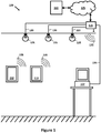
Figure 1 is a diagram of a lighting system and user equipment in communication therewith, according to embodiments of the invention. -
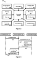
Figure 2 is a diagram showing the user equipment ofFigure 1 in more detail. -
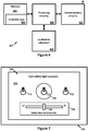
Figure 3 is a diagram showing interactions between the user equipment, system controller and remote server ofFigure 1 , during a process of granting access of the lighting system to the user equipment. -
Figure 4 is a diagram showing the system controller ofFigure 1 in more detail. -
Figure 5 is a diagram showing the remote server ofFigure 1 in more detail. -
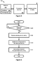
Figure 6 is a flowchart showing steps carried out by the remote server ofFigures 1 and5 , to dynamically update a priority rating associated with a user of the user equipment, in accordance with an embodiment of the invention. -
Figure 7 is a diagram of a user interface, presented on a screen of the user equipment ofFigures 1 and2 , for enabling a user to indicate a preferred setting for the lighting system, in accordance with an embodiment of the invention. - In overview, and with reference to
Figure 1 , in an embodiment of the invention alighting system 100 comprises a plurality oflight fixtures 105, asystem controller 107 and a wireless access point 115 (hereinafter, the "WAP 115"). Thelighting system 100 is connected via one or more internal and/orexternal networks 125 to aremote server 130. - Each of the
light fixtures 105 comprises one or more LED-based light sources, and is part of a respective ceiling-mounted light fixture arranged to emit light generally downwards. Thelight fixtures 105 are connected to the WAP 115 via awired channel 120, which comprises respective Ethernet cables in this embodiment. - The
system controller 107 is connected to the WAP 115 via thewired channel 120, and is configured to communicate thereby with all of thelight fixtures 105. Thesystem controller 107 is suitable for controlling thelight fixtures 105 individually, in groups of any two or more, or all at once. - As shown in
Figure 1 , in accordance with an embodiment of the invention there may be one or more instances ofuser equipment 110 in the vicinity of thelighting system 100, which is/are enabled to communicate with thelighting system 100. Theuser equipment 110 is enabled to communicate with theWAP 115 via awireless channel 135, which is a WiFi channel in this embodiment. Thus theuser equipment 110 can communicate with thesystem controller 107, e.g. to request control of the lighting system. - As shown in
Figure 2 , the user equipment 110 (which may be a smartphone or a tablet computer, for example) comprisesprocessing circuitry 200 which is communicatively coupled to a touch-sensitive display 205 and to a plurality of sensors. The plurality of sensors comprises: one ormore gyroscopes 210; one or more ambientlight sensors 215; one ormore accelerometers 220, including a three-axis accelerometer in this embodiment; one or more magnetometers (not shown); one ormore image sensors 225, which includes an integrated CCD camera in this embodiment; and one ormore proximity sensors 230. Theprocessing circuitry 200 is also communicatively coupled to radiofrequency ('RF')circuitry 245, which enables wireless communication via thewireless channel 135, and which includes aGPS subsystem 250. - The
user equipment 110 further comprisesmemory 235, which is communicatively coupled to theprocessing circuitry 200. Thememory 235 comprises, in addition to a number of conventional files and applications, a lighting control application 240 (hereinafter, the label 'user app' will be used for convenience, which should not be interpreted as a descriptive label). - When executed by the
processing circuitry 200, theuser app 240 causes theuser equipment 110 to carry out a method of controlling one or more of thelight fixtures 105, via thesystem controller 107. - When the
user app 240 is launched, theuser equipment 110 obtains the identities of thelight fixtures 105 using conventional discovery methods, via thewireless channel 135. - Referring now to
Figure 3 , in response to identifying thelight fixtures 105, theuser equipment 110 sends acontrol request 305 to thesystem controller 107. Thecontrol request 305 comprises an identity of a user of theuser equipment 110, which for instance may be the mac address of the user equipment 110 (which is assumed to be registered property of the user). - Turning briefly to
Figure 4 , thesystem controller 107 comprisesprocessing circuitry 400 connected tocommunications circuitry 415, whereby it receives thecontrol request 305 from theuser equipment 110. Thesystem controller 107 further comprisesmemory 405, which is communicatively coupled to theprocessing circuitry 400. Thememory 405 comprises, in addition to a number of conventional files and applications, a lighting control application 410 (hereinafter, the label 'controller app' will be used for convenience, which should not be interpreted as a descriptive label). When executing thecontroller app 410, thesystem controller 107 is configured to control thelight fixtures 105 in dependence on or more control requests received from theuser equipment 110, as will be described in more detail below. - Referring again to
Figure 3 , in response to receiving the control request from theuser equipment 110, thesystem controller 107 sends apriority rating request 310 to theremote server 130. Thepriority rating request 310 comprises the identity of the user, which thesystem controller 107 obtained from thecontrol request 305. - Turning briefly to
Figure 5 , theremoter server 130 comprisesprocessing circuitry 500 connected tocommunications circuitry 520, whereby it receives thepriority rating request 310 from thesystem controller 107. Theremoter server 130 further comprisesmemory 505, which is communicatively coupled to theprocessing circuitry 500. Thememory 505 comprises, in addition to a number of conventional files and applications, a lighting control application 515 (hereinafter, the label 'server app' will be used for convenience, which should not be interpreted as a descriptive label) and adatabase 510 of users and their respective 'priority ratings'. When executing theserver app 515, theremote server 130 is configured to dynamically update thedatabase 510, as will be described in more detail below. - Referring again to
Figure 3 , in response to receiving thepriority rating request 310 from thesystem controller 107, theremote server 130 updates the priority rating associated with the user in thedatabase 510. (Theremote server 130 obtains the identity of the user from thepriority rating request 310.) Theremote server 130 is configured to create a database entry for the user, including a priority rating, if one does not already exist; hereinafter, a reference to an/the "existing priority rating" should be interpreted so as to include such a newly-created priority rating. - As shown in
Figure 6 , the remote sever 130 is configured to discern S100 and respond to observed activity linked to the user. By receiving thepriority rating request 310, theremote server 130 obtains an indication that the user has arrived in, and therefore is present in, a predefined area associated with thelighting system 100. Theremote server 130 treats this as an observed activity linked to the user, and in response proceeds to retrieve S105 from the database 510 (or receive in any other suitable manner) an existing priority rating associated with the user in order to update it. - Next the
remote server 130 updates S110 the existing priority rating based on the observed activity. This updating may involve simply incrementing the existing priority rating, or it may involve increasing the existing priority rating on a sliding scale based on which type of activity is observed. For instance, if the user is present in the predefined area associated with thelighting system 100 at a prioritized time of day, e.g. before 8 am, then the existing priority rating may be increased by more than it would have been at other times of the day. This may act as an incentive to arrive early. As another example, if the user is present in a prioritized part of the predefined area, e.g. in a particular office of an office building, then the existing priority rating may be increased by more than it would have been for other parts of the office building. - The
remote server 130 then stores S115 the updated priority rating in memory, and sends S115 the updatedpriority rating 320 to thesystem controller 107 as a reply to thepriority rating request 310. - Referring again to
Figure 3 , in response to receiving the updatedpriority rating 315 from theremote server 130, thesystem controller 107 compares the updatedpriority rating 315 with a threshold. In this embodiment the threshold is a respective priority rating associated with another user, which may have been obtained in the same manner as described above, e.g. in response to the other user sending a control request to thesystem controller 107. - If the updated
priority rating 315 is above the threshold, thesystem controller 107 sends a grant-control message 320 to theuser equipment 110 as a reply to itscontrol request 305. The grant-control message 320 comprises a 'list of privileges', indicating which of thelight fixtures 105 can be controlled and to what extent. For instance, the user may be allowed to control only a subset of thelight fixtures 105, and only their dim levels. - In response to receiving the grant-
control message 320, theuser equipment 110 presents on its display 205 auser interface 700 for controlling thelight fixtures 105, as shown inFigure 7 . - The
user interface 700 comprises arepresentation 715 of thelight fixtures 105, which in this embodiment comprises a respective icon for each of thelight fixtures 105, shown as light bulb icons inFigure 7 . If the list of privileges indicates that the user is not allowed to control some of the light fixtures, the corresponding icons are displayed in such a way as to convey this to the user, e.g. they may be 'greyed out'. - The user can then select one of the
light fixtures 105 to control by touching thedisplay 205 where therepresentation 715 corresponding to thatlight fixture 105 is shown. In response to the user selection, theuser interface 700 shows anindication 720 of whichlight fixture 105 has been selected. In this embodiment theindication 720 is an icon overlay, shown inFigure 7 as a dashed line encircling theicon 715 corresponding to the selected one of thelight fixtures 105. - The
user interface 700 also comprises acontrol object 725 whereby one or more light settings of the selectedlight fixture 105 can be adjusted. In this embodiment thecontrol object 725 comprises aslider 730, which the user can 'drag' in order to indicate a desired light setting. As shown inFigure 7 , the position of theslider 730 represents a current dim level of the selectedlight fixture 105, and can be dragged towards "Lo" or towards "Hi" to dim or brighten the selected one of thelight fixtures 105, respectively. - In response to the user indicating a desired light setting for one or more of the light fixtures, via the
user interface 700, theuser equipment 110 sends a control message to thesystem controller 107. The control message identifies the one or more light fixtures and the desired light settings for each. - The
system controller 107, having granted control of thelighting system 100 to theuser equipment 110, will interpret the control message and provide appropriate control signals to the relevant light fixtures. - While an embodiment of the invention has been illustrated and described in detail in the drawings and foregoing description, such illustration and description are to be considered illustrative and not restrictive; the invention is not limited to the disclosed embodiments.
- For example, the user equipment described above may be a smartphone or a tablet computer, but in other embodiments it could be any other suitable user device. For instance, suitable user devices may include laptop computers, portable DVD players, portable audio players or the like.
- In various embodiments, the identity of a user may alternatively/additionally be obtained by other means. For instance, the user may enter an identifier (e.g. a username, user ID and/or password) into a wall-mounted control panel suitable for controlling the lighting system, or other shared-access system. The user may 'swipe' his or her ID card, or other near field communications (NFC) device, through/over a reader from which the identity of the user is then obtained.
- In various embodiments, the user equipment may communicate directly with the remote server (through a cellular link, for example), rather than via the system controller. In which case, the remote server may then communicate with the system controller, or even with the light fixtures themselves if they have network connectivity.
- In various embodiments, the above-described functions of the remote server (e.g. updating the priority rating associated with a user) and the system controller (e.g. comparing the priority rating with a threshold) are integrated into a single computer apparatus. The computer apparatus is thus arranged to obtain via an internal process the priority rating associated with a user, rather than receiving it from a separate computer apparatus such as the remote server. The computer apparatus may be part of the lighting system, or other shared-access system, or it may be 'in the cloud' i.e. part of an external network to which the lighting system, or other shared-access system, is connectable. In an embodiment the computer apparatus is, or is part of, the user equipment.
- In various embodiments, the system controller may perform 'arbitration' whereby granting control of the lighting system, or other shared-access system, entails allowing the user equipment to directly control the lighting system. Alternatively, as described in detail above, granting control to a user may mean allowing the user to indirectly control the lighting system, or other shared-access system. For example, the system controller will control the lighting system but in dependence on preferred settings of the user, either received from the user equipment or stored in a memory accessible by the system controller.
- In various embodiments, the threshold with which a user's priority rating is compared is derived from a priority ratings associated with another user, or from respective priority ratings associated with a plurality of other users. For example, the threshold may comprise a weighted version of another user's priority rating, biased upwards or downwards in dependence on factors such as a system administrator making manual (perhaps temporary) changes to allow more or fewer users to control the system. The threshold may comprise the mean, median or mode (or other suitable representative value) of the respective priority ratings of a plurality of other users, such as a particular class or group of users. In which case, the threshold should increase in response to an overall increase in the respective priority ratings of its users.
- In various embodiments, updating the priority rating associated with a user is done dynamically in response to obtaining an indication of one or more observed activities of the user. For instance, the user equipment may be configure to use its GPS subsystem to determine its location and then communicate that location to the system controller via any suitable means; thus the system controller may obtain an indication that the user equipment is present in a predefined area associated with the lighting system, or other shared-access system, which may trigger the updating.
- In various embodiments, the one or more observed activities comprises making one or more purchases or other financial transactions linked to the shared-access system. For instance, a user may book and pay for a hotel room for a night, e.g. at the hotel reception (perhaps using an NFC-enabled user device) or via the Internet, which causes the user's priority rating to be updated for the lighting system, or other shared-access system, in the hotel room. Thus that an indication that a purchase linked to the shared-access system has been made, and that the purchase is associated with an account linked to the user, is obtained from the system which processed the payment in respect of booking the room.
- In various embodiments, a user's priority rating could have a (weighted) contribution from his or her contacts/connections. The user may have an indirect connection to a location associated with the shared-access system, such as being connected via someone with a direct connection to that location, in which case a weighting based on the directly-connected person's priority rating could be applied.
- In various embodiments, a user may have multiple priority levels, whereby control of the shared-access system may be granted to more than one user concurrently, with different users controlling different aspects of the shared-access system. In a lighting system, for example, each of several users may be able to control different ones of the light fixtures, or one user may be able to control the color of the emitted light while a different user is able to control the intensity of the emitted light.
- In various embodiments, a user may have different priority levels for different parts/zones/subsystems of a shared-access system. In a hotel lighting system, for example, a hotel guest may have a lower priority rating in the hotel lobby than in his or her hotel room.
- In various embodiments, the light fixtures may be any suitable arrangement of one or more lighting units in a particular form factor, assembly, or package. A given lighting unit may include one or more light sources of same or different types (as noted above), and may have any one of a variety of mounting arrangements for the light source(s), enclosure/housing arrangements and shapes, and/or electrical and mechanical connection configurations. Additionally, a given lighting unit may be associated with (e.g., include, be coupled to and/or packaged together with) various other components (e.g., control circuitry) relating to the operation of the light source(s).
- In various embodiments, the IP-enabled light fixtures described above could be replaced or supplemented by other addressable light fixtures, e.g. DALI- and/or DMX-controlled light fixtures. Some embodiments may comprise non-addressable light fixtures.
- In various embodiments, the light sources may potentially comprise any suitable sources of light, such as LED-based sources, incandescent sources (e.g., filament lamps, halogen lamps), fluorescent sources, phosphorescent sources, high-intensity discharge sources (e.g., sodium vapor, mercury vapor, and metal halide lamps), lasers, other types of electroluminescent sources, candle-luminescent sources (e.g., gas mantles, carbon arc radiation sources), photo-luminescent sources (e.g., gaseous discharge sources), cathode luminescent sources using electronic satiation, galvano-luminescent sources, crystallo-luminescent sources, kine-luminescent sources, thermo-luminescent sources, triboluminescent sources, sonoluminescent sources, radioluminescent sources, and luminescent polymers.
- In various embodiments, the memory in the user equipment, in the system controller and in the remote server may be any suitable storage media, such as one or more of: volatile and non-volatile computer memory such as RAM, PROM, EPROM, and EEPROM, floppy disks, compact disks, optical disks, magnetic tape, etc. Various storage media may be fixed within the processor and/or controller, or may be transportable, such that the one or more programs stored thereon can be loaded into a processor or controller so as to implement various aspects of the present invention discussed herein. The terms "program" or "computer program" are used herein in a generic sense to refer to any type of computer code (e.g., software or microcode) that can be employed to program one or more processors or controllers.
- Other variations to the disclosed embodiments can be understood and effected by those skilled in the art in practicing the claimed invention, from a study of the drawings, the disclosure, and the appended claims.
- In the claims, the word "comprising" does not exclude other elements or steps, and the indefinite article "a" or "an" does not exclude a plurality.
- A single processor or other unit may fulfill the functions of several items recited in the claims. The mere fact that certain measures are recited in mutually different dependent claims does not indicate that a combination of these measures cannot be used to advantage.
- A computer program may be stored/distributed on a suitable computer readable medium, such as an optical storage medium or a solid-state medium supplied together with or as part of other hardware, but may also be distributed via other computer program products such as Internet/intranet downloads or via other wired or wireless telecommunication systems.
- Any reference signs in the claims should not be construed as limiting the scope.
Claims (14)
- A method of granting control of a shared-access system (100), comprising:obtaining (305) an identity of a user;obtaining (310, 315) a priority rating associated with the user, wherein the priority rating is updated in response to one or more observed activities of the user, the one or more observed activities being linked to the shared-access system (100);comparing the priority rating with a threshold; andgranting (320) control of at least a part of the shared-access system (100) to the user if the priority rating is above the threshold,characterised in that the threshold comprises, or is derived from, a respective priority rating which is associated with another user.
- The method of claim 1 wherein the one or more observed activities comprises being present in a predefined area associated with the shared-access system (100), and optionally in a prioritized part of the predefined area and/or at a prioritized time of day.
- The method of claim 2 further comprising:obtaining an indication that a user device (110) associated with the user is present in the predefined area associated with the shared-access system (100), and optionally which specifies the location of the user device (110) within the predefined area; andin response to obtaining the indication, updating the priority rating associated with the user.
- The method of any foregoing claim wherein the one or more observed activities comprises making one or more purchases linked to the shared-access system (100), and/or to the environment in which the shared-access system (100) or a part thereof is located.
- The method of claim 4 further comprising:obtaining an indication that a purchase has been made which is linked to the shared-access system (100), and that the purchase is associated with an account linked to the user; andin response to obtaining the indication, updating the priority rating associated with the user.
- The method of any foregoing claim wherein the one or more observed activities comprises becoming associated with the shared-access system (100) on an Internet-based networking site.
- The method of any foregoing claim comprising granting control of at least a part of the shared-access system (100) to the user, to the exclusion of any other user, if the priority rating is above the threshold.
- The method of any foregoing claim wherein granting control of at least a part of the shared-access system (100) to the user comprises automatically controlling said at least a part of the shared-access system (100) in accordance with predefined settings associated with the user.
- The method of any foregoing claim wherein granting control of at least a part of the shared-access system (100) to the user comprises enabling the user to provide one or more settings for controlling said at least a part of the shared-access system.
- The method of any foregoing claim wherein the shared-access system (100) comprises one or more lighting units (105), and wherein granting control of at least a part of the shared-access system (100) comprises granting control of at least one of the one or more lighting units (105).
- The method of claim 10, when dependent on claim 8 or claim 9, wherein the one or more settings are indicative of at least one of: a dimming level; a color; and an illumination pattern.
- A computer program (410) comprising computer-interpretable instructions which, when executed by processing circuitry (400) of a computing device (107), cause the computing device (107) to carry out the method of any foregoing claim.
- A computing device (107) for granting control of a shared-access system (100), comprising:a communications subsystem (415) for communicating with the shared-access system (100), and for receiving one or more inputs from outside the shared-access system (100);memory (405) in which is stored the computer program (410) of claim 12; andprocessing circuitry (400) connected to the communications subsystem (415) and the memory (405), which by executing the computer-interpretable instructions of the computer program (410) is configured to carry out the method of any one of the foregoing method claims.
- A lighting system (100) comprising one or more lighting units (105) and the computing device (107) of claim 13, wherein the computing device (107) is connected to the lighting units (105) for granting control thereof.
Priority Applications (1)
| Application Number | Priority Date | Filing Date | Title |
|---|---|---|---|
| PL13817979T PL2909977T3 (en) | 2012-10-17 | 2013-10-11 | Granting control of a shared system |
Applications Claiming Priority (2)
| Application Number | Priority Date | Filing Date | Title |
|---|---|---|---|
| US201261714874P | 2012-10-17 | 2012-10-17 | |
| PCT/IB2013/059308 WO2014060920A1 (en) | 2012-10-17 | 2013-10-11 | Granting control of a shared system |
Publications (2)
| Publication Number | Publication Date |
|---|---|
| EP2909977A1 EP2909977A1 (en) | 2015-08-26 |
| EP2909977B1 true EP2909977B1 (en) | 2019-08-21 |
Family
ID=49918747
Family Applications (1)
| Application Number | Title | Priority Date | Filing Date |
|---|---|---|---|
| EP13817979.1A Active EP2909977B1 (en) | 2012-10-17 | 2013-10-11 | Granting control of a shared system |
Country Status (8)
| Country | Link |
|---|---|
| US (1) | US9947156B2 (en) |
| EP (1) | EP2909977B1 (en) |
| JP (1) | JP6263190B2 (en) |
| CN (1) | CN104718724B (en) |
| ES (1) | ES2754311T3 (en) |
| PL (1) | PL2909977T3 (en) |
| RU (1) | RU2656686C2 (en) |
| WO (1) | WO2014060920A1 (en) |
Families Citing this family (6)
| Publication number | Priority date | Publication date | Assignee | Title |
|---|---|---|---|---|
| WO2015025235A1 (en) | 2013-08-23 | 2015-02-26 | Koninklijke Philips N.V. | Control of a lighting system |
| US10142838B2 (en) | 2014-08-05 | 2018-11-27 | Philips Lighting Holding B.V. | Context-aware controlling of multiple systems of controllable devices |
| US10057965B2 (en) | 2015-05-04 | 2018-08-21 | Fulham Company Limited | LED driver and lighting systems technologies |
| WO2018091310A1 (en) * | 2016-11-15 | 2018-05-24 | Philips Lighting Holding B.V. | Lighting system control |
| US10244610B2 (en) * | 2017-02-27 | 2019-03-26 | Illum Horticulture Llc | Method and apparatus for an intelligent lighting system |
| WO2018185123A1 (en) | 2017-04-06 | 2018-10-11 | Philips Lighting Holding B.V. | Controller and method for a lighting system |
Family Cites Families (20)
| Publication number | Priority date | Publication date | Assignee | Title |
|---|---|---|---|---|
| US7242152B2 (en) * | 1997-08-26 | 2007-07-10 | Color Kinetics Incorporated | Systems and methods of controlling light systems |
| US6370160B1 (en) * | 1998-12-29 | 2002-04-09 | Thomson Licensing S. A. | Base to handset epoch synchronization in multi-line wireless telephone |
| EP1057302A1 (en) | 1998-12-29 | 2000-12-06 | Koninklijke Philips Electronics N.V. | Home control system with distributed network devices |
| JP4329264B2 (en) * | 2000-12-27 | 2009-09-09 | セイコーエプソン株式会社 | Access authority level control apparatus and method |
| JP2003242229A (en) | 2002-02-15 | 2003-08-29 | Hitachi Building Systems Co Ltd | Support device for building user |
| US7298871B2 (en) | 2002-06-07 | 2007-11-20 | Koninklijke Philips Electronics N.V. | System and method for adapting the ambience of a local environment according to the location and personal preferences of people in the local environment |
| DE102006016268A1 (en) | 2006-04-06 | 2007-10-25 | Vis-à-pix GmbH | Controllable device controlling method, directly or by supply unit connected with control and regulation unit or supply unit, involves making decision by carried out control and regulation action in control |
| US7805529B2 (en) * | 2006-07-14 | 2010-09-28 | International Business Machines Corporation | Method and system for dynamically changing user session behavior based on user and/or group classification in response to application server demand |
| EP2315504B1 (en) * | 2007-05-09 | 2014-02-26 | Koninklijke Philips N.V. | A method and a system for controlling a lighting system |
| US8667144B2 (en) | 2007-07-25 | 2014-03-04 | Qualcomm Incorporated | Wireless architecture for traditional wire based protocol |
| US8098831B2 (en) * | 2008-05-15 | 2012-01-17 | Microsoft Corporation | Visual feedback in electronic entertainment system |
| US8427278B2 (en) * | 2008-10-17 | 2013-04-23 | Robert Bosch Gmbh | Automation and security system |
| WO2010079388A1 (en) | 2009-01-07 | 2010-07-15 | Koninklijke Philips Electronics N.V. | Intelligent controllable lighting networks and schemata therefore |
| EP2396928A1 (en) | 2009-02-10 | 2011-12-21 | Philips Intellectual Property & Standards GmbH | A system and method for controlling the access to a networked control system |
| JP5587995B2 (en) | 2009-06-09 | 2014-09-10 | コーニンクレッカ フィリップス エヌ ヴェ | System and apparatus for automatically retrieving and correcting personal preferences applicable to multiple controllable lighting networks |
| JP5883783B2 (en) | 2009-06-30 | 2016-03-15 | コーニンクレッカ フィリップス エヌ ヴェKoninklijke Philips N.V. | System and method for managing interaction with a controllable lighting network |
| US8418237B2 (en) | 2009-10-20 | 2013-04-09 | Microsoft Corporation | Resource access based on multiple credentials |
| CN101937194B (en) | 2010-09-27 | 2012-12-19 | 鸿富锦精密工业(深圳)有限公司 | Intelligence control system with learning function and method thereof |
| DK2829161T3 (en) * | 2012-03-19 | 2023-04-03 | Brainlit Ab | IMPROVED LIGHTING CONTROL SYSTEM |
| EP2859780B1 (en) * | 2012-06-11 | 2020-01-22 | Signify Holding B.V. | Methods and apparatus for storing, suggesting, and/or utilizing lighting settings |
-
2013
- 2013-10-11 ES ES13817979T patent/ES2754311T3/en active Active
- 2013-10-11 JP JP2015537390A patent/JP6263190B2/en not_active Expired - Fee Related
- 2013-10-11 RU RU2015118331A patent/RU2656686C2/en active
- 2013-10-11 WO PCT/IB2013/059308 patent/WO2014060920A1/en active Application Filing
- 2013-10-11 CN CN201380054377.9A patent/CN104718724B/en active Active
- 2013-10-11 US US14/436,788 patent/US9947156B2/en active Active
- 2013-10-11 EP EP13817979.1A patent/EP2909977B1/en active Active
- 2013-10-11 PL PL13817979T patent/PL2909977T3/en unknown
Non-Patent Citations (1)
| Title |
|---|
| None * |
Also Published As
| Publication number | Publication date |
|---|---|
| RU2656686C2 (en) | 2018-06-06 |
| CN104718724B (en) | 2019-07-23 |
| EP2909977A1 (en) | 2015-08-26 |
| US20160180617A1 (en) | 2016-06-23 |
| JP6263190B2 (en) | 2018-01-17 |
| PL2909977T3 (en) | 2020-03-31 |
| ES2754311T3 (en) | 2020-04-16 |
| RU2015118331A (en) | 2016-12-10 |
| WO2014060920A1 (en) | 2014-04-24 |
| US9947156B2 (en) | 2018-04-17 |
| CN104718724A (en) | 2015-06-17 |
| JP2016500904A (en) | 2016-01-14 |
Similar Documents
| Publication | Publication Date | Title |
|---|---|---|
| EP2909977B1 (en) | Granting control of a shared system | |
| JP6650475B2 (en) | Home automation system including device signature pairing and related methods | |
| US20180124903A1 (en) | Network light switch with mechanical/electrical interface port | |
| US10524197B2 (en) | Network device source entity triggered device configuration setup | |
| EP3042544B1 (en) | System for remotely controlling a controllable device | |
| US10645089B2 (en) | Terminal for internet of things and operation method of the same | |
| US20190166124A1 (en) | Apparatus and method by which user device in home network system transmits home-device-related information | |
| US10460243B2 (en) | Network device predictive modeling | |
| JP6739456B2 (en) | Home automation system including cloud and home message queue synchronization, and related methods | |
| US20160087838A1 (en) | Retail triggered device configuration setup | |
| KR102487902B1 (en) | Method and apparatus for controlling home devices | |
| JP2019506073A (en) | Set up and launch additional devices | |
| US9892630B1 (en) | Network light switch with mechanical/electrical interface port | |
| JP6588530B2 (en) | Context adaptive control of controllable devices in multiple systems | |
| US11166132B2 (en) | Environment control system for controlling environmental conditions in a building | |
| JP2024044957A (en) | Equipment management system, mobile terminal and program |
Legal Events
| Date | Code | Title | Description |
|---|---|---|---|
| PUAI | Public reference made under article 153(3) epc to a published international application that has entered the european phase |
Free format text: ORIGINAL CODE: 0009012 |
|
| 17P | Request for examination filed |
Effective date: 20150518 |
|
| AK | Designated contracting states |
Kind code of ref document: A1 Designated state(s): AL AT BE BG CH CY CZ DE DK EE ES FI FR GB GR HR HU IE IS IT LI LT LU LV MC MK MT NL NO PL PT RO RS SE SI SK SM TR |
|
| AX | Request for extension of the european patent |
Extension state: BA ME |
|
| DAX | Request for extension of the european patent (deleted) | ||
| RAP1 | Party data changed (applicant data changed or rights of an application transferred) |
Owner name: PHILIPS LIGHTING HOLDING B.V. |
|
| RIN1 | Information on inventor provided before grant (corrected) |
Inventor name: NOLAN, JULIAN CHARLES Inventor name: VAN EEUWIJK, ALEXANDER HENRICUS WALTHERUS Inventor name: WINDRIDGE, MELANIE JANE Inventor name: JALINK, CORNELIS JOJAKIM |
|
| RAP1 | Party data changed (applicant data changed or rights of an application transferred) |
Owner name: PHILIPS LIGHTING HOLDING B.V. |
|
| RAP1 | Party data changed (applicant data changed or rights of an application transferred) |
Owner name: SIGNIFY HOLDING B.V. |
|
| GRAP | Despatch of communication of intention to grant a patent |
Free format text: ORIGINAL CODE: EPIDOSNIGR1 |
|
| STAA | Information on the status of an ep patent application or granted ep patent |
Free format text: STATUS: GRANT OF PATENT IS INTENDED |
|
| RIC1 | Information provided on ipc code assigned before grant |
Ipc: H04L 12/28 20060101AFI20190305BHEP Ipc: H04L 29/08 20060101ALI20190305BHEP Ipc: H04W 4/021 20180101ALI20190305BHEP Ipc: G07C 9/00 20060101ALI20190305BHEP Ipc: H05B 37/02 20060101ALI20190305BHEP |
|
| INTG | Intention to grant announced |
Effective date: 20190326 |
|
| RIN1 | Information on inventor provided before grant (corrected) |
Inventor name: WINDRIDGE, MELANIE JANE Inventor name: JALINK, CORNELIS JOJAKIM Inventor name: VAN EEUWIJK, ALEXANDER HENRICUS WALTHERUS Inventor name: NOLAN, JULIAN CHARLES |
|
| GRAS | Grant fee paid |
Free format text: ORIGINAL CODE: EPIDOSNIGR3 |
|
| GRAA | (expected) grant |
Free format text: ORIGINAL CODE: 0009210 |
|
| STAA | Information on the status of an ep patent application or granted ep patent |
Free format text: STATUS: THE PATENT HAS BEEN GRANTED |
|
| AK | Designated contracting states |
Kind code of ref document: B1 Designated state(s): AL AT BE BG CH CY CZ DE DK EE ES FI FR GB GR HR HU IE IS IT LI LT LU LV MC MK MT NL NO PL PT RO RS SE SI SK SM TR |
|
| REG | Reference to a national code |
Ref country code: GB Ref legal event code: FG4D |
|
| REG | Reference to a national code |
Ref country code: CH Ref legal event code: EP |
|
| REG | Reference to a national code |
Ref country code: DE Ref legal event code: R096 Ref document number: 602013059539 Country of ref document: DE |
|
| REG | Reference to a national code |
Ref country code: AT Ref legal event code: REF Ref document number: 1170998 Country of ref document: AT Kind code of ref document: T Effective date: 20190915 |
|
| REG | Reference to a national code |
Ref country code: IE Ref legal event code: FG4D |
|
| REG | Reference to a national code |
Ref country code: NL Ref legal event code: FP |
|
| REG | Reference to a national code |
Ref country code: SE Ref legal event code: TRGR |
|
| REG | Reference to a national code |
Ref country code: LT Ref legal event code: MG4D |
|
| PG25 | Lapsed in a contracting state [announced via postgrant information from national office to epo] |
Ref country code: PT Free format text: LAPSE BECAUSE OF FAILURE TO SUBMIT A TRANSLATION OF THE DESCRIPTION OR TO PAY THE FEE WITHIN THE PRESCRIBED TIME-LIMIT Effective date: 20191223 Ref country code: LT Free format text: LAPSE BECAUSE OF FAILURE TO SUBMIT A TRANSLATION OF THE DESCRIPTION OR TO PAY THE FEE WITHIN THE PRESCRIBED TIME-LIMIT Effective date: 20190821 Ref country code: NO Free format text: LAPSE BECAUSE OF FAILURE TO SUBMIT A TRANSLATION OF THE DESCRIPTION OR TO PAY THE FEE WITHIN THE PRESCRIBED TIME-LIMIT Effective date: 20191121 Ref country code: BG Free format text: LAPSE BECAUSE OF FAILURE TO SUBMIT A TRANSLATION OF THE DESCRIPTION OR TO PAY THE FEE WITHIN THE PRESCRIBED TIME-LIMIT Effective date: 20191121 Ref country code: HR Free format text: LAPSE BECAUSE OF FAILURE TO SUBMIT A TRANSLATION OF THE DESCRIPTION OR TO PAY THE FEE WITHIN THE PRESCRIBED TIME-LIMIT Effective date: 20190821 |
|
| PG25 | Lapsed in a contracting state [announced via postgrant information from national office to epo] |
Ref country code: RS Free format text: LAPSE BECAUSE OF FAILURE TO SUBMIT A TRANSLATION OF THE DESCRIPTION OR TO PAY THE FEE WITHIN THE PRESCRIBED TIME-LIMIT Effective date: 20190821 Ref country code: IS Free format text: LAPSE BECAUSE OF FAILURE TO SUBMIT A TRANSLATION OF THE DESCRIPTION OR TO PAY THE FEE WITHIN THE PRESCRIBED TIME-LIMIT Effective date: 20191221 Ref country code: GR Free format text: LAPSE BECAUSE OF FAILURE TO SUBMIT A TRANSLATION OF THE DESCRIPTION OR TO PAY THE FEE WITHIN THE PRESCRIBED TIME-LIMIT Effective date: 20191122 Ref country code: AL Free format text: LAPSE BECAUSE OF FAILURE TO SUBMIT A TRANSLATION OF THE DESCRIPTION OR TO PAY THE FEE WITHIN THE PRESCRIBED TIME-LIMIT Effective date: 20190821 Ref country code: LV Free format text: LAPSE BECAUSE OF FAILURE TO SUBMIT A TRANSLATION OF THE DESCRIPTION OR TO PAY THE FEE WITHIN THE PRESCRIBED TIME-LIMIT Effective date: 20190821 |
|
| REG | Reference to a national code |
Ref country code: CH Ref legal event code: NV Representative=s name: VALIPAT S.A. C/O BOVARD SA NEUCHATEL, CH |
|
| REG | Reference to a national code |
Ref country code: AT Ref legal event code: MK05 Ref document number: 1170998 Country of ref document: AT Kind code of ref document: T Effective date: 20190821 |
|
| PG25 | Lapsed in a contracting state [announced via postgrant information from national office to epo] |
Ref country code: TR Free format text: LAPSE BECAUSE OF FAILURE TO SUBMIT A TRANSLATION OF THE DESCRIPTION OR TO PAY THE FEE WITHIN THE PRESCRIBED TIME-LIMIT Effective date: 20190821 |
|
| REG | Reference to a national code |
Ref country code: ES Ref legal event code: FG2A Ref document number: 2754311 Country of ref document: ES Kind code of ref document: T3 Effective date: 20200416 |
|
| PG25 | Lapsed in a contracting state [announced via postgrant information from national office to epo] |
Ref country code: RO Free format text: LAPSE BECAUSE OF FAILURE TO SUBMIT A TRANSLATION OF THE DESCRIPTION OR TO PAY THE FEE WITHIN THE PRESCRIBED TIME-LIMIT Effective date: 20190821 Ref country code: DK Free format text: LAPSE BECAUSE OF FAILURE TO SUBMIT A TRANSLATION OF THE DESCRIPTION OR TO PAY THE FEE WITHIN THE PRESCRIBED TIME-LIMIT Effective date: 20190821 Ref country code: AT Free format text: LAPSE BECAUSE OF FAILURE TO SUBMIT A TRANSLATION OF THE DESCRIPTION OR TO PAY THE FEE WITHIN THE PRESCRIBED TIME-LIMIT Effective date: 20190821 Ref country code: EE Free format text: LAPSE BECAUSE OF FAILURE TO SUBMIT A TRANSLATION OF THE DESCRIPTION OR TO PAY THE FEE WITHIN THE PRESCRIBED TIME-LIMIT Effective date: 20190821 |
|
| PG25 | Lapsed in a contracting state [announced via postgrant information from national office to epo] |
Ref country code: CZ Free format text: LAPSE BECAUSE OF FAILURE TO SUBMIT A TRANSLATION OF THE DESCRIPTION OR TO PAY THE FEE WITHIN THE PRESCRIBED TIME-LIMIT Effective date: 20190821 Ref country code: IS Free format text: LAPSE BECAUSE OF FAILURE TO SUBMIT A TRANSLATION OF THE DESCRIPTION OR TO PAY THE FEE WITHIN THE PRESCRIBED TIME-LIMIT Effective date: 20200224 Ref country code: MC Free format text: LAPSE BECAUSE OF FAILURE TO SUBMIT A TRANSLATION OF THE DESCRIPTION OR TO PAY THE FEE WITHIN THE PRESCRIBED TIME-LIMIT Effective date: 20190821 Ref country code: SK Free format text: LAPSE BECAUSE OF FAILURE TO SUBMIT A TRANSLATION OF THE DESCRIPTION OR TO PAY THE FEE WITHIN THE PRESCRIBED TIME-LIMIT Effective date: 20190821 Ref country code: SM Free format text: LAPSE BECAUSE OF FAILURE TO SUBMIT A TRANSLATION OF THE DESCRIPTION OR TO PAY THE FEE WITHIN THE PRESCRIBED TIME-LIMIT Effective date: 20190821 |
|
| REG | Reference to a national code |
Ref country code: DE Ref legal event code: R097 Ref document number: 602013059539 Country of ref document: DE |
|
| PLBE | No opposition filed within time limit |
Free format text: ORIGINAL CODE: 0009261 |
|
| STAA | Information on the status of an ep patent application or granted ep patent |
Free format text: STATUS: NO OPPOSITION FILED WITHIN TIME LIMIT |
|
| PG2D | Information on lapse in contracting state deleted |
Ref country code: IS |
|
| PG25 | Lapsed in a contracting state [announced via postgrant information from national office to epo] |
Ref country code: LU Free format text: LAPSE BECAUSE OF NON-PAYMENT OF DUE FEES Effective date: 20191011 |
|
| 26N | No opposition filed |
Effective date: 20200603 |
|
| REG | Reference to a national code |
Ref country code: BE Ref legal event code: MM Effective date: 20191031 |
|
| PG25 | Lapsed in a contracting state [announced via postgrant information from national office to epo] |
Ref country code: BE Free format text: LAPSE BECAUSE OF NON-PAYMENT OF DUE FEES Effective date: 20191031 Ref country code: SI Free format text: LAPSE BECAUSE OF FAILURE TO SUBMIT A TRANSLATION OF THE DESCRIPTION OR TO PAY THE FEE WITHIN THE PRESCRIBED TIME-LIMIT Effective date: 20190821 |
|
| PG25 | Lapsed in a contracting state [announced via postgrant information from national office to epo] |
Ref country code: IE Free format text: LAPSE BECAUSE OF NON-PAYMENT OF DUE FEES Effective date: 20191011 |
|
| PG25 | Lapsed in a contracting state [announced via postgrant information from national office to epo] |
Ref country code: CY Free format text: LAPSE BECAUSE OF FAILURE TO SUBMIT A TRANSLATION OF THE DESCRIPTION OR TO PAY THE FEE WITHIN THE PRESCRIBED TIME-LIMIT Effective date: 20190821 |
|
| PG25 | Lapsed in a contracting state [announced via postgrant information from national office to epo] |
Ref country code: HU Free format text: LAPSE BECAUSE OF FAILURE TO SUBMIT A TRANSLATION OF THE DESCRIPTION OR TO PAY THE FEE WITHIN THE PRESCRIBED TIME-LIMIT; INVALID AB INITIO Effective date: 20131011 Ref country code: MT Free format text: LAPSE BECAUSE OF FAILURE TO SUBMIT A TRANSLATION OF THE DESCRIPTION OR TO PAY THE FEE WITHIN THE PRESCRIBED TIME-LIMIT Effective date: 20190821 |
|
| PG25 | Lapsed in a contracting state [announced via postgrant information from national office to epo] |
Ref country code: MK Free format text: LAPSE BECAUSE OF FAILURE TO SUBMIT A TRANSLATION OF THE DESCRIPTION OR TO PAY THE FEE WITHIN THE PRESCRIBED TIME-LIMIT Effective date: 20190821 |
|
| PGFP | Annual fee paid to national office [announced via postgrant information from national office to epo] |
Ref country code: DE Payment date: 20221227 Year of fee payment: 10 |
|
| P01 | Opt-out of the competence of the unified patent court (upc) registered |
Effective date: 20230421 |
|
| PGFP | Annual fee paid to national office [announced via postgrant information from national office to epo] |
Ref country code: PL Payment date: 20230929 Year of fee payment: 11 Ref country code: NL Payment date: 20231026 Year of fee payment: 11 |
|
| PGFP | Annual fee paid to national office [announced via postgrant information from national office to epo] |
Ref country code: GB Payment date: 20231024 Year of fee payment: 11 |
|
| PGFP | Annual fee paid to national office [announced via postgrant information from national office to epo] |
Ref country code: ES Payment date: 20231110 Year of fee payment: 11 |
|
| PGFP | Annual fee paid to national office [announced via postgrant information from national office to epo] |
Ref country code: SE Payment date: 20231023 Year of fee payment: 11 Ref country code: IT Payment date: 20231024 Year of fee payment: 11 Ref country code: FR Payment date: 20231026 Year of fee payment: 11 Ref country code: FI Payment date: 20231026 Year of fee payment: 11 Ref country code: CH Payment date: 20231102 Year of fee payment: 11 |