EP2909907B1 - Full-duplex signaling for arc event protection - Google Patents
Full-duplex signaling for arc event protection Download PDFInfo
- Publication number
- EP2909907B1 EP2909907B1 EP13780010.8A EP13780010A EP2909907B1 EP 2909907 B1 EP2909907 B1 EP 2909907B1 EP 13780010 A EP13780010 A EP 13780010A EP 2909907 B1 EP2909907 B1 EP 2909907B1
- Authority
- EP
- European Patent Office
- Prior art keywords
- conductors
- current
- pair
- magnitude
- trip
- Prior art date
- Legal status (The legal status is an assumption and is not a legal conclusion. Google has not performed a legal analysis and makes no representation as to the accuracy of the status listed.)
- Active
Links
- 230000011664 signaling Effects 0.000 title claims description 71
- 239000004020 conductor Substances 0.000 claims description 108
- 238000011144 upstream manufacturing Methods 0.000 claims description 12
- 230000008859 change Effects 0.000 description 9
- 238000010586 diagram Methods 0.000 description 7
- 238000012544 monitoring process Methods 0.000 description 6
- 238000000034 method Methods 0.000 description 4
- 230000008878 coupling Effects 0.000 description 3
- 238000010168 coupling process Methods 0.000 description 3
- 238000005859 coupling reaction Methods 0.000 description 3
- 230000007423 decrease Effects 0.000 description 3
- 230000004044 response Effects 0.000 description 3
- 238000000926 separation method Methods 0.000 description 3
- RYGMFSIKBFXOCR-UHFFFAOYSA-N Copper Chemical compound [Cu] RYGMFSIKBFXOCR-UHFFFAOYSA-N 0.000 description 2
- 230000001010 compromised effect Effects 0.000 description 2
- 229910052802 copper Inorganic materials 0.000 description 2
- 239000010949 copper Substances 0.000 description 2
- 238000001514 detection method Methods 0.000 description 2
- 230000036039 immunity Effects 0.000 description 2
- 238000002955 isolation Methods 0.000 description 2
- 230000000704 physical effect Effects 0.000 description 2
- 238000012545 processing Methods 0.000 description 2
- 230000002159 abnormal effect Effects 0.000 description 1
- 230000003466 anti-cipated effect Effects 0.000 description 1
- 230000005540 biological transmission Effects 0.000 description 1
- 239000000470 constituent Substances 0.000 description 1
- 230000003247 decreasing effect Effects 0.000 description 1
- 238000011156 evaluation Methods 0.000 description 1
- 230000003993 interaction Effects 0.000 description 1
- 230000007246 mechanism Effects 0.000 description 1
- 239000002184 metal Substances 0.000 description 1
- 229910052751 metal Inorganic materials 0.000 description 1
- 230000003287 optical effect Effects 0.000 description 1
- 239000007787 solid Substances 0.000 description 1
- 230000002459 sustained effect Effects 0.000 description 1
Images


Classifications
-
- H—ELECTRICITY
- H02—GENERATION; CONVERSION OR DISTRIBUTION OF ELECTRIC POWER
- H02H—EMERGENCY PROTECTIVE CIRCUIT ARRANGEMENTS
- H02H1/00—Details of emergency protective circuit arrangements
- H02H1/0007—Details of emergency protective circuit arrangements concerning the detecting means
- H02H1/0015—Using arc detectors
- H02H1/0023—Using arc detectors sensing non electrical parameters, e.g. by optical, pneumatic, thermal or sonic sensors
-
- H—ELECTRICITY
- H02—GENERATION; CONVERSION OR DISTRIBUTION OF ELECTRIC POWER
- H02H—EMERGENCY PROTECTIVE CIRCUIT ARRANGEMENTS
- H02H1/00—Details of emergency protective circuit arrangements
- H02H1/0061—Details of emergency protective circuit arrangements concerning transmission of signals
- H02H1/0084—Details of emergency protective circuit arrangements concerning transmission of signals by means of pilot wires or a telephone network; watching of these wires
-
- H—ELECTRICITY
- H02—GENERATION; CONVERSION OR DISTRIBUTION OF ELECTRIC POWER
- H02J—CIRCUIT ARRANGEMENTS OR SYSTEMS FOR SUPPLYING OR DISTRIBUTING ELECTRIC POWER; SYSTEMS FOR STORING ELECTRIC ENERGY
- H02J13/00—Circuit arrangements for providing remote indication of network conditions, e.g. an instantaneous record of the open or closed condition of each circuitbreaker in the network; Circuit arrangements for providing remote control of switching means in a power distribution network, e.g. switching in and out of current consumers by using a pulse code signal carried by the network
- H02J13/00006—Circuit arrangements for providing remote indication of network conditions, e.g. an instantaneous record of the open or closed condition of each circuitbreaker in the network; Circuit arrangements for providing remote control of switching means in a power distribution network, e.g. switching in and out of current consumers by using a pulse code signal carried by the network characterised by information or instructions transport means between the monitoring, controlling or managing units and monitored, controlled or operated power network element or electrical equipment
- H02J13/00016—Circuit arrangements for providing remote indication of network conditions, e.g. an instantaneous record of the open or closed condition of each circuitbreaker in the network; Circuit arrangements for providing remote control of switching means in a power distribution network, e.g. switching in and out of current consumers by using a pulse code signal carried by the network characterised by information or instructions transport means between the monitoring, controlling or managing units and monitored, controlled or operated power network element or electrical equipment using a wired telecommunication network or a data transmission bus
-
- H—ELECTRICITY
- H02—GENERATION; CONVERSION OR DISTRIBUTION OF ELECTRIC POWER
- H02J—CIRCUIT ARRANGEMENTS OR SYSTEMS FOR SUPPLYING OR DISTRIBUTING ELECTRIC POWER; SYSTEMS FOR STORING ELECTRIC ENERGY
- H02J13/00—Circuit arrangements for providing remote indication of network conditions, e.g. an instantaneous record of the open or closed condition of each circuitbreaker in the network; Circuit arrangements for providing remote control of switching means in a power distribution network, e.g. switching in and out of current consumers by using a pulse code signal carried by the network
- H02J13/00032—Systems characterised by the controlled or operated power network elements or equipment, the power network elements or equipment not otherwise provided for
- H02J13/00036—Systems characterised by the controlled or operated power network elements or equipment, the power network elements or equipment not otherwise provided for the elements or equipment being or involving switches, relays or circuit breakers
- H02J13/0004—Systems characterised by the controlled or operated power network elements or equipment, the power network elements or equipment not otherwise provided for the elements or equipment being or involving switches, relays or circuit breakers involved in a protection system
-
- H—ELECTRICITY
- H02—GENERATION; CONVERSION OR DISTRIBUTION OF ELECTRIC POWER
- H02H—EMERGENCY PROTECTIVE CIRCUIT ARRANGEMENTS
- H02H7/00—Emergency protective circuit arrangements specially adapted for specific types of electric machines or apparatus or for sectionalised protection of cable or line systems, and effecting automatic switching in the event of an undesired change from normal working conditions
- H02H7/26—Sectionalised protection of cable or line systems, e.g. for disconnecting a section on which a short-circuit, earth fault, or arc discharge has occured
- H02H7/261—Sectionalised protection of cable or line systems, e.g. for disconnecting a section on which a short-circuit, earth fault, or arc discharge has occured involving signal transmission between at least two stations
-
- Y—GENERAL TAGGING OF NEW TECHNOLOGICAL DEVELOPMENTS; GENERAL TAGGING OF CROSS-SECTIONAL TECHNOLOGIES SPANNING OVER SEVERAL SECTIONS OF THE IPC; TECHNICAL SUBJECTS COVERED BY FORMER USPC CROSS-REFERENCE ART COLLECTIONS [XRACs] AND DIGESTS
- Y02—TECHNOLOGIES OR APPLICATIONS FOR MITIGATION OR ADAPTATION AGAINST CLIMATE CHANGE
- Y02B—CLIMATE CHANGE MITIGATION TECHNOLOGIES RELATED TO BUILDINGS, e.g. HOUSING, HOUSE APPLIANCES OR RELATED END-USER APPLICATIONS
- Y02B90/00—Enabling technologies or technologies with a potential or indirect contribution to GHG emissions mitigation
- Y02B90/20—Smart grids as enabling technology in buildings sector
-
- Y—GENERAL TAGGING OF NEW TECHNOLOGICAL DEVELOPMENTS; GENERAL TAGGING OF CROSS-SECTIONAL TECHNOLOGIES SPANNING OVER SEVERAL SECTIONS OF THE IPC; TECHNICAL SUBJECTS COVERED BY FORMER USPC CROSS-REFERENCE ART COLLECTIONS [XRACs] AND DIGESTS
- Y02—TECHNOLOGIES OR APPLICATIONS FOR MITIGATION OR ADAPTATION AGAINST CLIMATE CHANGE
- Y02E—REDUCTION OF GREENHOUSE GAS [GHG] EMISSIONS, RELATED TO ENERGY GENERATION, TRANSMISSION OR DISTRIBUTION
- Y02E60/00—Enabling technologies; Technologies with a potential or indirect contribution to GHG emissions mitigation
-
- Y—GENERAL TAGGING OF NEW TECHNOLOGICAL DEVELOPMENTS; GENERAL TAGGING OF CROSS-SECTIONAL TECHNOLOGIES SPANNING OVER SEVERAL SECTIONS OF THE IPC; TECHNICAL SUBJECTS COVERED BY FORMER USPC CROSS-REFERENCE ART COLLECTIONS [XRACs] AND DIGESTS
- Y04—INFORMATION OR COMMUNICATION TECHNOLOGIES HAVING AN IMPACT ON OTHER TECHNOLOGY AREAS
- Y04S—SYSTEMS INTEGRATING TECHNOLOGIES RELATED TO POWER NETWORK OPERATION, COMMUNICATION OR INFORMATION TECHNOLOGIES FOR IMPROVING THE ELECTRICAL POWER GENERATION, TRANSMISSION, DISTRIBUTION, MANAGEMENT OR USAGE, i.e. SMART GRIDS
- Y04S10/00—Systems supporting electrical power generation, transmission or distribution
- Y04S10/20—Systems supporting electrical power generation, transmission or distribution using protection elements, arrangements or systems
-
- Y—GENERAL TAGGING OF NEW TECHNOLOGICAL DEVELOPMENTS; GENERAL TAGGING OF CROSS-SECTIONAL TECHNOLOGIES SPANNING OVER SEVERAL SECTIONS OF THE IPC; TECHNICAL SUBJECTS COVERED BY FORMER USPC CROSS-REFERENCE ART COLLECTIONS [XRACs] AND DIGESTS
- Y04—INFORMATION OR COMMUNICATION TECHNOLOGIES HAVING AN IMPACT ON OTHER TECHNOLOGY AREAS
- Y04S—SYSTEMS INTEGRATING TECHNOLOGIES RELATED TO POWER NETWORK OPERATION, COMMUNICATION OR INFORMATION TECHNOLOGIES FOR IMPROVING THE ELECTRICAL POWER GENERATION, TRANSMISSION, DISTRIBUTION, MANAGEMENT OR USAGE, i.e. SMART GRIDS
- Y04S40/00—Systems for electrical power generation, transmission, distribution or end-user application management characterised by the use of communication or information technologies, or communication or information technology specific aspects supporting them
- Y04S40/12—Systems for electrical power generation, transmission, distribution or end-user application management characterised by the use of communication or information technologies, or communication or information technology specific aspects supporting them characterised by data transport means between the monitoring, controlling or managing units and monitored, controlled or operated electrical equipment
- Y04S40/124—Systems for electrical power generation, transmission, distribution or end-user application management characterised by the use of communication or information technologies, or communication or information technology specific aspects supporting them characterised by data transport means between the monitoring, controlling or managing units and monitored, controlled or operated electrical equipment using wired telecommunication networks or data transmission busses
Definitions
- the present invention generally relates to arc event protection, and particularly relates to full-duplex signaling between a trip system and an arc flash protection system.
- a power protection and distribution assembly is typically installed at every building, factory, or similar facility, where the main electrical power from the grid enters the facility.
- the power protection and distribution assembly sometimes referred to as "switchgear,” usually includes an enclosure with a main circuit breaker at the electrical point furthest upstream, or closest to the external main power grid; a power distribution bus, which may comprise copper bars for each positive power phase and one or more ground bus bars; and one or more area circuit breakers, each protecting an electrical circuit distributing power to an area of the facility.
- the purpose of the circuit breakers is to protect downstream circuits from overcurrent conditions, such as would occur in the event of a short circuit.
- a trip system trips a circuit breaker upon the detection of an overcurrent condition.
- One type of trip system detects an overcurrent condition by detecting excessive heat generated by large currents moving through resistive conductors. While such trip systems will interrupt a faulty circuit in time to avoid a fire, sensitive downstream electrical equipment may still be damaged by the overcurrent condition prior to current flow interruption.
- trip systems can provide a quicker circuit interruption operation of the main breaker prior to or during dangerous arcing events through interaction with an arc flash protection system.
- An arc event i.e. current traveling through air, manifests itself visibly in the form of a spark, arc, flame, glow of molten metal, etc. that results from an arcing condition.
- the system may operate an auxiliary arc diverter mechanism or send a control signal to the trip system directing the trip system to trip the main circuit breaker, or both.
- the arc flash protection system detects an arc event when optical or other conditions characteristic of a flash are detected.
- the arc flash protection system detects light as one of these conditions.
- the trip system detects abnormal current flowing through the conductors as another one of the arcing conditions, and signals the condition to the arc flash protection system.
- One or more embodiments herein provide high speed and highly robust full-duplex signaling between a trip system and an arc flash protection system, without meaningfully increasing the complexity and cost of those systems. This high-speed, robust signaling facilitates timely and accurate tripping of an upstream circuit breaker to protect downstream circuits from damage.
- a trip system herein is configured to send a current status signal to an arc flash protection system indicating whether current characteristic of an arc event has been detected.
- the arc flash protection system evaluates this current status signal along with a light status signal indicating whether light characteristic of an arc event has been detected as well. Based on this evaluation, the arc flash protection system is configured to send a control signal to the trip system for controlling the trip system to trip the upstream breaker and thereby protect downstream circuits from damage.
- the trip system and the arc flash protection system each include a full-duplex signaling module for simultaneously signaling the current status signal and the control signal between the systems over a pair of conductors coupling the systems together.
- each signaling module sends one of the signals by modulating the magnitude of a current through or a voltage across the pair of conductors, and receives the other signal by demodulating the magnitude of the current through or the voltage across the pair of conductors, as distinctively modulated by the other signaling module.
- one of the signaling modules modulates the magnitude of the current through the pair of conductors, while the other one of the signaling modules modulates the magnitude of the voltage across the pair of conductors.
- the signaling between the modules is asymmetric in the sense that the modules do not modulate the same physical property.
- the signaling modules both modulate either the current through the pair of conductors or the voltage across the pair of conductors, but the modules do so in ways that are distinguishable.
- Some asymmetric embodiments advantageously decouple voltage magnitude modulation by one of the signaling modules and current magnitude modulation by the other signaling module.
- the signaling module performing current magnitude modulation does so using an adjustable impedance circuit.
- this adjustable impedance circuit is configured to automatically self-adjust its impedance in order to substantially counteract any current magnitude modulation attributable to voltage magnitude modulation performed by the other signaling module. This means that signaling of the current status signal and signaling of the control signal remain substantially independent without having to introduce significant noise tolerance margins.
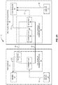
- FIG. 1 depicts an exemplary power protection and distribution assembly 10 for a facility.
- Electrical power from a power source 12 is received by switchgear 14, which houses a main circuit breaker 16, power distribution bus 18, and one or more area circuit breakers 20A, 20B, ... 20N.
- the main breaker 16 protects the entire facility, and is rated to pass the highest anticipated sustained current.
- the power distribution bus 18 may comprise solid copper bars capable of conducting large currents.
- Each area circuit breaker 20A, 20B, ... 20N downstream from the main circuit breaker 16 is rated for a lower current, and distributes power to separate downstream circuits 22A, 22B, ... 22N. Separate downstream circuits 22A, 22B, ... 22N typically distribute electrical power to separate areas of the facility.
- the switchgear 14 includes a trip system 24 and an arc flash protection system 26 that are cooperatively configured to trip the main circuit breaker 16 when an overcurrent condition occurs, such as during the detection of an arc event. Tripping the main circuit breaker 16 in this way isolates the power distribution bus 18 from the power source 12 in a timely manner, before the power distribution bus 18 is damaged.
- the timeliness and accuracy of the breaker's tripping depends on the speed and robustness of signaling between the trip system 24 and the arc flash protection system 26.
- One or more embodiments herein advantageously provide high speed and highly robust signaling, and thus timely and accurate breaker tripping, without meaningfully increasing the complexity and/or cost of the system 10.
- a status circuit 28 included in the trip system 24 is configured to generate a current status signal 30 indicating whether or not current characteristic of an arc event is detected.
- the status circuit 28 receives the output 32 of a current sensor 34 disposed in series with the main breaker 16.
- the status circuit 28 compares the sensor output 32 to a current level threshold that has been set to distinguish between a current level that is attributable to an arc event and a current level that is not.
- the status circuit 28 When the sensor output 32 indicates a current level that meets or exceeds the arcing threshold, the status circuit 28 generates the current status signal 30 to indicate that a current characteristic of an arc event has been detected. Otherwise, the status circuit 28 generates the current status signal 30 to indicate that such a current has not been detected.
- the trip system 24 further includes a signaling module 36 that is configured to send the current status signal 30 to the arc flash protection system 26.
- the signaling module 36 is full-duplex in the sense that the module 36 can send the current status signal 30 to the arc flash protection system 26 while simultaneously receiving signaling from the arc flash protection system 26. Regardless, the signaling module 36 sends the current status signal 30 to the arc flash protection system 26 by modulating the magnitude of a current through or a voltage across a pair of conductors 38 coupling the trip system 24 to the arc flash protection system 26.
- the arc flash protection system 26 correspondingly includes a full-duplex signaling module 40 configured to receive the current status signal 30' from the trip system 24 by demodulating the magnitude of the current through or the voltage across the pair of conductors 38.
- the arc flash protection system 26 obtains a light status signal 42 indicating whether or not light characteristic of an arc event is detected.
- the arc flash protection system 26 obtains this light status signal 42 by generating it based on the output 46 of one or more light sensors 48 disposed within the switchgear 14, e.g., proximal to the one or more area circuit breakers 20.
- the arch flash protection system 26 includes a status circuit 44 configured to compare the sensor output 46 to a light level threshold that has been set to distinguish between a light level that is attributable to an arc event and a light level that is not.
- the status circuit 44 When the sensor output 46 indicates a light level that meets or exceeds the threshold, the status circuit 44 generates the light status signal 42 to indicate that light characteristic of an arc event has been detected. Otherwise, the status circuit 44 generates the light status signal 42 to indicate that such light has not been detected.
- a controller 50 included in the arc flash protection system 26 Based on the current status signal 30' received from the trip system 24 and the light status signal 42 generated by the status circuit 44, a controller 50 included in the arc flash protection system 26 generates a control signal 52 for controlling the trip system 24 to trip the main circuit breaker 16.
- the controller 50 generates the control signal 52 to direct the trip system 24 to trip the main breaker 16, responsive to the light status signal 42 and the current status signal 30' indicating that both light and current characteristic of an arc event have been detected. Otherwise, if either light or current characteristic of an arc event has not been detected, the controller 50 generates the control signal 52 to direct the trip system 24 to maintain its current state, i.e. no trip signal is generated.
- the arc flash protection system's full-duplex signaling module 40 sends this control signal 52 to the trip system 24 by modulating the magnitude of the current through or the voltage across the pair of conductors 38.
- Modulation performed by the arc flash protection system's full-duplex signaling module 40 in this regard is distinctive from the modulation performed by the trip system's full-duplex signaling module 36.
- one of the signaling modules 36, 40 modulates the magnitude of the current through the pair of conductors 38, while the other one of the signaling modules 36, 40 modulates the magnitude of the voltage across the pair of conductors 38.
- the signaling between the modules 36, 40 is asymmetric in the sense that the modules 36, 40 do not modulate the same physical property.
- the signaling modules 36, 40 both modulate either the current through the pair of conductors 38 or the voltage across the pair of conductors 38, but the modules 36, 40 do so in ways that are distinguishable.
- the trip system's signaling module 36 correspondingly receives the control signal 52' by demodulating that current or voltage.
- a driver 54 included in the trip system 24 is configured to trip the main breaker 16 in accordance with this control signal 52'. That is, the driver 54 either signals the main breaker 16 to trip or maintain the current state of the main breaker 16 depending on the command indicated by the control signal 52'.
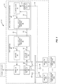
- Figures 2A-2D illustrate additional details according to one or more asymmetric embodiments.
- the trip system's signaling module 36 includes a transmitter 56 in series with a receiver 58 between the conductors 38.
- the arc flash protection system's signaling module 40 includes a transmitter 60 in parallel with a receiver 62 (and the conductors 38).
- the trip system's transmitter 56 sends the current status signal 30 by modulating the magnitude of the voltage across the conductors 38, while the trip system's receiver 58 receives the control signal 52' by demodulating the magnitude of the current through the conductors 38 (which is the same as the current through the trip system's transmitter 56).
- the arc flash protection system's transmitter 60 sends the control signal 52 by modulating the magnitude of the current through the conductors 38, while the arc flash protection system's receiver 62 receives the current status signal 30' by demodulating the magnitude of the voltage across the conductors 38.
- demodulating the magnitude of the voltage across the conductors 38 entails the arc flash protection system's receiver 62 monitoring the full voltage across the conductors 38. As shown in Figure 2A , for instance, the full voltage across the conductors 38 falls across the transmitter 60 and the receiver 62 monitors this full voltage. In other embodiments, though, demodulating the magnitude of the voltage across the conductors 38 entails the receiver 62 monitoring only a part of that full voltage. For example, where the full voltage across the conductors 38 is divided between the transmitter 60 and one or more other components (not shown) in series with the transmitter 60, demodulation may entail monitoring the voltage across one or more of those other components, or monitoring the voltage across the transmitter 60.
- FIG. 2B illustrates one implementation of the asymmetric embodiment shown in Figure 2A .
- the trip system's transmitter 56 includes an adjustable voltage source 64.
- the transmitter 56 in this case is configured to modulate the magnitude of the voltage across the conductors 38 by adjusting the voltage output of the adjustable voltage source 64, responsive to the current status signal 30.
- the arc flash protection system's receiver 62 correspondingly includes a voltage sensor 66 (e.g., an analog isolator) configured to monitor the magnitude of the voltage across the conductors 38 for demodulation.
- a voltage sensor 66 e.g., an analog isolator
- the arc flash protection system's transmitter 60 includes an adjustable impedance circuit 68.
- the transmitter 60 in this case is configured to modulate the magnitude of the current through the conductors 38 by adjusting the impedance of the adjustable impedance circuit 68.
- the trip system's receiver 58 correspondingly includes a current sensor 70 configured to monitor the magnitude of this current for demodulation.
- the current sensor 70 comprises an operational amplifier 74 connected across a sensing element 72 such as a small shunt resistor.
- the adjustable impedance circuit 68 in Figure 2B comprises a switchable impedance that is configured to selectively connect different fixed-valued impedances across the conductors 38, responsive to the control signal 52.
- the adjustable impedance circuit 68 comprises a controllable impedance that is configured to vary in impedance responsive to the control signal 52.
- the signaling modules 36, 40 in one or more embodiments are configured to tolerate at least some coupling between voltage magnitude modulation by the adjustable voltage source 64 and current magnitude modulation by the adjustable impedance circuit 68.
- the adjustable voltage source 64 changes the magnitude of the voltage across the conductors 38 in order to send the current status signal 30
- the magnitude of the current through the conductors 38 changes as well.
- Appropriate noise margins at the receiver 58 permit the receiver 58 to distinguish between current magnitude modulation attributable to the adjustable impedance circuit 68 sending the control signal 52 and current magnitude modulation incidentally attributable to the adjustable voltage source 64 sending the current status signal 30.
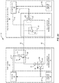
- Figure 2C illustrates more sophisticated embodiments that substantially decouple voltage magnitude modulation by the adjustable voltage source 64 and current magnitude modulation by the adjustable impedance circuit 68.
- the arc flash protection system's transmitter 60 includes an adjustable impedance circuit 68 that is configured to automatically self-adjust its impedance in order to substantially counteract any modulation of the magnitude of the current through the conductors 38 attributable to modulation by the trip system 24 of the magnitude of the voltage across the conductors 38.
- the adjustable impedance circuit 68 in Figure 2C is configured to self-adjust its impedance as needed in order to regulate or otherwise maintain the current through the conductors 38 at a magnitude representative of the control signal 52.
- the circuit 68 in this regard includes a current sensor 78 (similar to current sensor 70) that is configured to monitor the magnitude of the current through the conductors 38.
- the circuit 68 also includes an impedance controller 76 that is configured to determine the difference between the current magnitude representative of the control signal 52 (e.g., via isolator 75) and the current magnitude through the conductors 38, as monitored by the current sensor 78.
- the impedance controller 76 controls an adjustable impedance 80 included in the circuit 68, as needed, to minimize this determined difference.
- the impedance controller 76 of Figure 2C observes this voltage magnitude change as a corresponding current magnitude change and controls the adjustable impedance 80 to counteract that change.
- the impedance controller 76 responsively increases the impedance of the adjustable impedance 80 so that the current magnitude through the conductors 38 decreases back down to the current magnitude representative of the control signal 52.
- the impedance controller 76 conversely decreases the impedance of the adjustable impedance 80 responsive to the trip system's transmitter 56 decreasing the voltage magnitude across the conductors 38, so that the current magnitude through the conductors 38 increases back up to the current magnitude representative of the control signal 52.
- voltage and current magnitude modulation advantageously decoupled in this way, voltage magnitude changes do not produce corresponding current magnitude changes. This means that signaling of the current status signal 30 and signaling of the control signal 52 remain substantially independent without having to introduce significant noise tolerance margins, especially when galvanic isolation is employed at one of the signaling modules 36, 40.
- the trip system's transmitter 56 is configured to set the voltage output of the adjustable voltage source 64 to a first voltage magnitude (e.g., 5V) in order to send a binary 0 as the current status signal 30 (e.g., indicating that current characteristic of an arc event has not been detected).
- the arc flash protection system's voltage sensor 66 senses the resulting voltage across the conductors 38.
- the controller 50 of Figure 2B recognizes the sensed voltage as a binary 0 sent from the trip system's status circuit 30.
- the arc flash protection system's adjustable impedance circuit 68 is configured to regulate the current through the conductors 38 to a first current magnitude (e.g., 4ma) in order to simultaneously send a binary 0 as the control signal 52 (e.g., indicating that the driver 54 is to maintain the current state of the main breaker 16).
- the trip system's current sensor 70 senses the resulting current through the conductors 38. When this sensed current falls within a first predefined current magnitude range (e.g., 3-5ma), the driver 54 recognizes the sensed current as a binary 0 sent from the controller 50.
- the trip system's status circuit 28 switches from generating the current status signal 30 to indicate that current characteristic of an arc event has not been detected, to generating the current status signal 30 to indicate that such a current has been detected.
- the trip system's transmitter 56 correspondingly sets the voltage output of the adjustable voltage source 64 to a second voltage magnitude (e.g., 8V) in order to send a binary 1 as the current status signal 30.
- the arc flash protection system's voltage sensor 66 senses the resulting voltage across the conductors 38.
- the controller 50 recognizes the sensed voltage as a binary 1 sent from the trip system's status circuit 30. Meanwhile, the arc flash protection system's adjustable impedance circuit 68 automatically self-adjusts its impedance in order to maintain the current through the conductors 38 at the first current magnitude (e.g., 4ma), despite the change in the voltage magnitude across the conductors 38.
- a second predefined voltage magnitude range e.g., >7V, to provide a noise margin between 6-7V
- the trip system's current sensor 70 continues to sense current within the first predefined current magnitude range, and the driver 54 continues to recognize the sensed current as a binary 0 sent from the controller 50 so as to maintain the current state of the main breaker 16 unless directed to do so by the controller 50.
- the controller 50 if the light status signal 42 indicates that light characteristic of an arc event is detected as well, then the controller 50 generates the control signal 52 to indicate that the driver 54 is to signal a trip of the main breaker 16.
- the arc flash protection system's adjustable impedance circuit 68 correspondingly adjusts in impedance (e.g., decreases) so that the current through the conductors 38 changes from the first current magnitude (e.g., 4ma) to a second current magnitude (e.g., 10ma) associated with a binary 1.
- the trip system's current sensor 70 senses this change in current through the conductors 38.
- the driver 54 recognizes the sensed current as a binary 1 sent from the controller 50. The driver 54 then trips the main breaker 16.
- a second predefined current magnitude range e.g., >8ma, to provide a noise margin between 5-8ma
- the driver 54 in some embodiments is configured to selectively ignore (blank) the current output of the trip system's receiver 58 for a predefined duration after a state change of the current status signal 30'.
- the driver 54 tolerates the amount of time needed in practice for the arc flash protection system's adjustable impedance circuit 68 to respond to the voltage magnitude modulation associated with that state change.
- the predefined duration in one or more embodiments therefore corresponds to the longest expected settling time of the adjustable impedance circuit 68. This duration may be kept small by judicious adjustment of response times.
- the same selective ignoring may similarly extend to the arc flash protection system's controller 50, in order to tolerate the settling time of the adjustable voltage source 64.
- the embodiments just described prove particularly convenient for supervising the integrity of the signaling path provided by the conductors 38 between the modules 36, 40.
- the arc flash protection system's controller 50 or an integrity monitoring circuit (not shown) included in the arc flash protection system's receiver 62 monitors for whether the voltage across the conductors 38 falls within a third predefined voltage magnitude range (e.g., 0-3V, to provide noise margin between 3-4V). If the voltage falls within this range, the integrity of the signaling path has been compromised and a signaling path error is declared.
- the trip system's driver 54 or an integrity monitoring circuit (not shown) included in the trip system's receiver 58 monitors for whether the current through the conductors 38 falls within a third predefined current magnitude range (e.g., 0-2ma, to provide noise margin between 2-3ma). If the current falls within this range, the integrity of the signaling path has been compromised and a signaling path error is declared.
- a third predefined current magnitude range e.g., 0-2ma, to provide noise margin between 2-3ma.
- the modules 36, 40 may be configured in other embodiments for bipolar magnitude modulation. Further, although the above embodiments employed certain separation bands or noise margins between different discrete levels representative of different magnitude modulation states, these separation bands may be arbitrarily adjusted to achieve optimal noise immunity. Still further, although the current status signal 30 and the control signal 52 were described above as being represented by a single change in state of the voltage or current magnitude, the signals 30, 52 in other embodiments may be represented by a train of state changes. Moreover, although the signaling modules 36, 40 were described above as using modulation between different discrete voltage and current magnitudes, the modules 36, 40 in other embodiments use modulation between different continuous voltage and current magnitudes. The rapidity of such modulation is limited only by the response times of the transmitters 56, 60, the response times of the receivers 58, 62, and the transmission characteristics of the conductors 38.
- Figure 2D illustrates a different implementation of the asymmetric embodiment shown in Figure 2A .
- the transmitter 56 comprises an impedance circuit 82.
- the transmitter 56 is configured to modulate the magnitude of the voltage across the conductors 38 by adjusting the impedance of the impedance circuit 82, responsive to the current status signal 30.
- the impedance circuit 82 includes switched impedance element 84 that is in series with a fixed voltage source 86.
- Figure 2D is otherwise the same as Figure 2B .
- the asymmetric embodiments discussed above prove advantageous in achieving highly robust full-duplex signaling.
- the asymmetric embodiments achieve high overall noise immunity by permitting the separation bands of logic high and low signal levels to be arbitrarily adjusted.
- the asymmetric embodiments prove more complex in terms of their hardware requirements and backwards compatibility than the symmetric configurations herein. These symmetric configurations still prove advantageous in terms of their robustness, albeit to a lesser extent than the asymmetric embodiments.
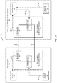
- Figures 3A-3B illustrate additional details according to one or more symmetric configurations.
- the trip system's signaling module 36 includes a transmitter 90 in series with a receiver 92 between the conductors 38.
- the arc flash protection system's signaling module 40 likewise includes a transmitter 94 in series with a receiver 96 between the conductors.
- the trip system's transmitter 90 is configured to send the current status signal 30 by modulating the magnitude of the current through the conductors 38, while the trip system's receiver 92 is configured to receive the control signal 52' by demodulating the magnitude of the current through the conductors 38, as distinctively modulated by the arc flash protection system's transmitter 94.
- the arc flash protection system's transmitter 94 is configured to send the control signal 52 by modulating the magnitude of the current through the conductors 38
- the arc flash protection system's receiver 96 is configured to receive the current status signal 30' by demodulating the magnitude of the current through the conductors 38, as distinctively modulated by the trip system's transmitter 90.
- Figure 3B illustrates one implementation of the symmetric configuration shown in Figure 3A .
- the trip system's transmitter 90 includes a switched impedance element 98 that is in series with a fixed voltage source 100.
- the transmitter 90 in this case is configured to modulate the magnitude of the current through the conductors 38 by switching the transistor associated with the switched impedance element 98, responsive to the current status signal 30.
- the arc flash protection system's receiver 96 correspondingly includes a current sensor 102 configured to monitor the magnitude of the current through the conductors 38 for demodulation.
- the arc flash protection system's transmitter 94 includes a switched impedance element 104.
- the transmitter 94 is configured to modulate the magnitude of the current through the conductors 38 by switching the transistor associated with the switched impedance element 104, responsive to the control signal 52.
- the trip system's receiver 92 correspondingly includes a current sensor 105 configured to monitor the magnitude of the current through the conductors 38 for demodulation.
- the trip system's receiver 92 is configured to distinguish modulation of the current by the arc flash protection system's transmitter 94 from modulation of the magnitude of the current by the trip system's own transmitter 90, based on a state or change in state of the current status signal 30.
- the receiver 92 includes one or more receiver processing circuits 106 configured to receive the current status signal 30 from the status circuit 28 and to identify current magnitude modulations imposed by the arc flash protection system's transmitter 94 as a function of that signal 30.
- the arc flash protection system's receiver 96 similarly includes one or more receiver processing circuits 108 configured to receive the control signal 52 and to identify current magnitude modulations imposed by the trip system's transmitter 90 as a function of that signal 52.
- the signaling modules 36, 40 herein are effectively interchangeable between the trip system 24 and the arc flash protection system 26.
- the trip system's signaling module 36 sends the current status signal 30 in the same way that the flash protection system's signaling module 40 was described above as sending the control signal 52.
- the flash protection system's signaling module 40 sends the control signal 52 in the same way that the trip system's signaling module 36 was described above as sending the current status signal 52.
- embodiments herein extend to scenarios where at least one of the systems 24, 26 is interconnected to one or more other trip systems and/or one or more other arc flash protection systems.
- multiple trip systems may be connected in series between paired conductors for controlling the tripping of different circuit breakers according to different control signals received from the arc flash protection systems.
- Appropriate selection of individual voltage magnitude ranges for the different trip systems 24 would allow the arc flash protection system 26 to uniquely distinguish different current status signals received from the different systems 24.
- multiple arc flash protection systems 26 may be connected to the same trip system 24 by different pairs of conductors 38. Appropriate selection of individual current magnitude ranges for different arc flash protection systems 26 would allow the trip system 24 to uniquely distinguish different control signals received from the different systems 26.
- various combinations of these embodiments are also envisioned herein.
- the pair of conductors 38 herein may consist of any type of conductors.
- the conductors 38 comprise a twisted pair of wires.
- the conductors 38 comprise a coaxial cable.
Description
- The present invention generally relates to arc event protection, and particularly relates to full-duplex signaling between a trip system and an arc flash protection system.
- A power protection and distribution assembly is typically installed at every building, factory, or similar facility, where the main electrical power from the grid enters the facility. The power protection and distribution assembly, sometimes referred to as "switchgear," usually includes an enclosure with a main circuit breaker at the electrical point furthest upstream, or closest to the external main power grid; a power distribution bus, which may comprise copper bars for each positive power phase and one or more ground bus bars; and one or more area circuit breakers, each protecting an electrical circuit distributing power to an area of the facility. The purpose of the circuit breakers is to protect downstream circuits from overcurrent conditions, such as would occur in the event of a short circuit.
- A trip system trips a circuit breaker upon the detection of an overcurrent condition. One type of trip system detects an overcurrent condition by detecting excessive heat generated by large currents moving through resistive conductors. While such trip systems will interrupt a faulty circuit in time to avoid a fire, sensitive downstream electrical equipment may still be damaged by the overcurrent condition prior to current flow interruption.
- Other functions of trip systems can provide a quicker circuit interruption operation of the main breaker prior to or during dangerous arcing events through interaction with an arc flash protection system. An arc event, i.e. current traveling through air, manifests itself visibly in the form of a spark, arc, flame, glow of molten metal, etc. that results from an arcing condition. When the arc flash protection system detects such an arc event, the system may operate an auxiliary arc diverter mechanism or send a control signal to the trip system directing the trip system to trip the main circuit breaker, or both.
- The arc flash protection system detects an arc event when optical or other conditions characteristic of a flash are detected. The arc flash protection system detects light as one of these conditions. The trip system detects abnormal current flowing through the conductors as another one of the arcing conditions, and signals the condition to the arc flash protection system.
- With signaling between the trip system and the arc flash protection system occurring within the electrical enclosure to prevent damage from arc flash occurrences, the ability of the systems to communicate status information, and therefore provide timely and accurate circuit interruption, depends on the speed and robustness of the signaling. Providing high speed and highly robust signaling, without meaningfully increasing the complexity and/or cost of the systems, or reducing same; has heretofore proven problematic.
US5701226 ,US5933308 andUS2010/57386 are examples of prior art power protection and distribution method and system. - Therefrom
US5701226 represents the closest prior art of the present invention. The Background section of the description of the present invention is provided to place embodiments of the present invention in technological and operational context, to assist those of skill in the art in understanding their scope and utility. Unless explicitly identified as such, no statement herein is admitted to be prior art merely by its inclusion in the Background section. - Due to the electromagnetic, spacing, and wiring constraints of an enclosed electrical distribution environment, it is desirable to provide robust signaling capabilities in order to maximize the efficiency and functionality for arc event protection in a power protection and distribution assembly. The present invention defined by the appended independent claims addresses these concerns with a full-duplex signaling arrangement between constituent trip and arc flash protection systems of the power protection and distribution assembly.
- The following presents a simplified summary of the disclosure in order to provide a basic understanding to those of skill in the art. This summary is not an extensive overview of the disclosure. Nor is the summary intended to identify key/critical elements of embodiments of the invention or otherwise delineate the scope of the invention. The sole purpose of this summary is to present some concepts disclosed herein in a simplified form as a prelude to the more detailed description that is presented later.
- One or more embodiments herein provide high speed and highly robust full-duplex signaling between a trip system and an arc flash protection system, without meaningfully increasing the complexity and cost of those systems. This high-speed, robust signaling facilitates timely and accurate tripping of an upstream circuit breaker to protect downstream circuits from damage.
- More particularly, a trip system herein is configured to send a current status signal to an arc flash protection system indicating whether current characteristic of an arc event has been detected. The arc flash protection system evaluates this current status signal along with a light status signal indicating whether light characteristic of an arc event has been detected as well. Based on this evaluation, the arc flash protection system is configured to send a control signal to the trip system for controlling the trip system to trip the upstream breaker and thereby protect downstream circuits from damage.
- The trip system and the arc flash protection system each include a full-duplex signaling module for simultaneously signaling the current status signal and the control signal between the systems over a pair of conductors coupling the systems together. Notably, each signaling module sends one of the signals by modulating the magnitude of a current through or a voltage across the pair of conductors, and receives the other signal by demodulating the magnitude of the current through or the voltage across the pair of conductors, as distinctively modulated by the other signaling module.
- In some embodiments, for example, one of the signaling modules modulates the magnitude of the current through the pair of conductors, while the other one of the signaling modules modulates the magnitude of the voltage across the pair of conductors. In this case, the signaling between the modules is asymmetric in the sense that the modules do not modulate the same physical property. In other "symmetric" configurations by contrast, the signaling modules both modulate either the current through the pair of conductors or the voltage across the pair of conductors, but the modules do so in ways that are distinguishable.
- Some asymmetric embodiments advantageously decouple voltage magnitude modulation by one of the signaling modules and current magnitude modulation by the other signaling module. In one embodiment, for example, the signaling module performing current magnitude modulation does so using an adjustable impedance circuit. Notably, this adjustable impedance circuit is configured to automatically self-adjust its impedance in order to substantially counteract any current magnitude modulation attributable to voltage magnitude modulation performed by the other signaling module. This means that signaling of the current status signal and signaling of the control signal remain substantially independent without having to introduce significant noise tolerance margins.
- Embodiments of the present invention will now be described more fully hereinafter with reference to some of the accompanying drawings, in which embodiments of the invention are shown. However, this invention should not be construed as limited to the embodiments set forth herein. Rather, these embodiments are provided so that this disclosure will be thorough and complete, and will fully convey the scope of the invention to those skilled in the art. Like numbers refer to like elements throughout.
-
Figure 1 is a block diagram of a power protection and distribution assembly configured according to one or more embodiments. -
Figure 2A is a block diagram of a trip system and arc flash protection system configured according to one or more asymmetric embodiments herein. -
Figure 2B is a schematic diagram illustrating one implementation of the asymmetric embodiment shown inFigure 2A . -
Figure 2C is a schematic diagram of an adjustable impedance circuit shown inFigure 2B , according to one or more embodiments. -
Figure 2D is a schematic diagram illustrating a different implementation of the asymmetric embodiment shown inFigure 2A . -
Figure 3A is a block diagram of an exemplary trip system and arc flash protection system configured according to one or more symmetric configuration herein. -
Figure 3B is a schematic diagram illustrating one exemplary implementation of the symmetric configuration shown inFigure 3A . - It should be understood at the outset that although illustrative implementations of one or more embodiments of the present disclosure are provided below, the disclosed systems and/or methods may be implemented using any number of techniques, whether currently known or in existence. The disclosure should in no way be limited to the illustrative implementations, drawings, and techniques illustrated below, including the exemplary designs and implementations illustrated and described herein, but may be modified within the scope of the appended claims along with their full scope of equivalents.
-
Figure 1 depicts an exemplary power protection anddistribution assembly 10 for a facility. Electrical power from apower source 12 is received byswitchgear 14, which houses amain circuit breaker 16,power distribution bus 18, and one or morearea circuit breakers 20A, 20B, ... 20N. Themain breaker 16 protects the entire facility, and is rated to pass the highest anticipated sustained current. Thepower distribution bus 18 may comprise solid copper bars capable of conducting large currents. Eacharea circuit breaker 20A, 20B, ... 20N downstream from themain circuit breaker 16 is rated for a lower current, and distributes power to separatedownstream circuits 22A, 22B, ... 22N. Separatedownstream circuits 22A, 22B, ... 22N typically distribute electrical power to separate areas of the facility. - When the power distribution bus 18 (or one of its component parts) experiences a short circuit or an arc flash event, the
main circuit breaker 16 may experience current flow in excess of its rated capacity. This is referred to as an overcurrent condition. Theswitchgear 14 includes atrip system 24 and an arcflash protection system 26 that are cooperatively configured to trip themain circuit breaker 16 when an overcurrent condition occurs, such as during the detection of an arc event. Tripping themain circuit breaker 16 in this way isolates thepower distribution bus 18 from thepower source 12 in a timely manner, before thepower distribution bus 18 is damaged. The timeliness and accuracy of the breaker's tripping, though, depends on the speed and robustness of signaling between thetrip system 24 and the arcflash protection system 26. One or more embodiments herein advantageously provide high speed and highly robust signaling, and thus timely and accurate breaker tripping, without meaningfully increasing the complexity and/or cost of thesystem 10. - In this regard, a
status circuit 28 included in thetrip system 24 is configured to generate acurrent status signal 30 indicating whether or not current characteristic of an arc event is detected. In some embodiments, for example, thestatus circuit 28 receives theoutput 32 of acurrent sensor 34 disposed in series with themain breaker 16. In this case, thestatus circuit 28 compares thesensor output 32 to a current level threshold that has been set to distinguish between a current level that is attributable to an arc event and a current level that is not. When thesensor output 32 indicates a current level that meets or exceeds the arcing threshold, thestatus circuit 28 generates thecurrent status signal 30 to indicate that a current characteristic of an arc event has been detected. Otherwise, thestatus circuit 28 generates thecurrent status signal 30 to indicate that such a current has not been detected. - The
trip system 24 further includes asignaling module 36 that is configured to send thecurrent status signal 30 to the arcflash protection system 26. Thesignaling module 36 is full-duplex in the sense that themodule 36 can send thecurrent status signal 30 to the arcflash protection system 26 while simultaneously receiving signaling from the arcflash protection system 26. Regardless, thesignaling module 36 sends thecurrent status signal 30 to the arcflash protection system 26 by modulating the magnitude of a current through or a voltage across a pair ofconductors 38 coupling thetrip system 24 to the arcflash protection system 26. The arcflash protection system 26 correspondingly includes a full-duplex signaling module 40 configured to receive the current status signal 30' from thetrip system 24 by demodulating the magnitude of the current through or the voltage across the pair ofconductors 38. - In addition to obtaining the current status signal 30' indicating whether or not current characteristic of an arc event is detected, the arc
flash protection system 26 obtains alight status signal 42 indicating whether or not light characteristic of an arc event is detected. In at least some embodiments, the arcflash protection system 26 obtains thislight status signal 42 by generating it based on theoutput 46 of one or morelight sensors 48 disposed within theswitchgear 14, e.g., proximal to the one or more area circuit breakers 20. In one such embodiment, for example, the archflash protection system 26 includes astatus circuit 44 configured to compare thesensor output 46 to a light level threshold that has been set to distinguish between a light level that is attributable to an arc event and a light level that is not. When thesensor output 46 indicates a light level that meets or exceeds the threshold, thestatus circuit 44 generates thelight status signal 42 to indicate that light characteristic of an arc event has been detected. Otherwise, thestatus circuit 44 generates thelight status signal 42 to indicate that such light has not been detected. - Based on the current status signal 30' received from the
trip system 24 and thelight status signal 42 generated by thestatus circuit 44, acontroller 50 included in the arcflash protection system 26 generates acontrol signal 52 for controlling thetrip system 24 to trip themain circuit breaker 16. In one embodiment, for example, thecontroller 50 generates thecontrol signal 52 to direct thetrip system 24 to trip themain breaker 16, responsive to thelight status signal 42 and the current status signal 30' indicating that both light and current characteristic of an arc event have been detected. Otherwise, if either light or current characteristic of an arc event has not been detected, thecontroller 50 generates thecontrol signal 52 to direct thetrip system 24 to maintain its current state, i.e. no trip signal is generated. - Regardless, the arc flash protection system's full-
duplex signaling module 40 sends thiscontrol signal 52 to thetrip system 24 by modulating the magnitude of the current through or the voltage across the pair ofconductors 38. Modulation performed by the arc flash protection system's full-duplex signaling module 40 in this regard is distinctive from the modulation performed by the trip system's full-duplex signaling module 36. In some embodiments, for example, one of the signalingmodules conductors 38, while the other one of the signalingmodules conductors 38. In this case, the signaling between themodules modules modules conductors 38 or the voltage across the pair ofconductors 38, but themodules - With the arc flash protection system's
signaling module 40 sending thecontrol signal 52 by distinctively modulating the current through or the voltage across the pair ofconductors 38, the trip system'ssignaling module 36 correspondingly receives the control signal 52' by demodulating that current or voltage. Adriver 54 included in thetrip system 24 is configured to trip themain breaker 16 in accordance with this control signal 52'. That is, thedriver 54 either signals themain breaker 16 to trip or maintain the current state of themain breaker 16 depending on the command indicated by the control signal 52'. -
Figures 2A-2D illustrate additional details according to one or more asymmetric embodiments. As shown inFigure 2A , the trip system'ssignaling module 36 includes atransmitter 56 in series with areceiver 58 between theconductors 38. The arc flash protection system'ssignaling module 40, by contrast, includes atransmitter 60 in parallel with a receiver 62 (and the conductors 38). The trip system'stransmitter 56 sends thecurrent status signal 30 by modulating the magnitude of the voltage across theconductors 38, while the trip system'sreceiver 58 receives the control signal 52' by demodulating the magnitude of the current through the conductors 38 (which is the same as the current through the trip system's transmitter 56). Correspondingly, the arc flash protection system'stransmitter 60 sends thecontrol signal 52 by modulating the magnitude of the current through theconductors 38, while the arc flash protection system'sreceiver 62 receives the current status signal 30' by demodulating the magnitude of the voltage across theconductors 38. - In some embodiments, demodulating the magnitude of the voltage across the
conductors 38 entails the arc flash protection system'sreceiver 62 monitoring the full voltage across theconductors 38. As shown inFigure 2A , for instance, the full voltage across theconductors 38 falls across thetransmitter 60 and thereceiver 62 monitors this full voltage. In other embodiments, though, demodulating the magnitude of the voltage across theconductors 38 entails thereceiver 62 monitoring only a part of that full voltage. For example, where the full voltage across theconductors 38 is divided between thetransmitter 60 and one or more other components (not shown) in series with thetransmitter 60, demodulation may entail monitoring the voltage across one or more of those other components, or monitoring the voltage across thetransmitter 60. -
Figure 2B illustrates one implementation of the asymmetric embodiment shown inFigure 2A . InFigure 2B , the trip system'stransmitter 56 includes anadjustable voltage source 64. Thetransmitter 56 in this case is configured to modulate the magnitude of the voltage across theconductors 38 by adjusting the voltage output of theadjustable voltage source 64, responsive to thecurrent status signal 30. The arc flash protection system'sreceiver 62 correspondingly includes a voltage sensor 66 (e.g., an analog isolator) configured to monitor the magnitude of the voltage across theconductors 38 for demodulation. - Also in
Figure 2B , the arc flash protection system'stransmitter 60 includes anadjustable impedance circuit 68. Thetransmitter 60 in this case is configured to modulate the magnitude of the current through theconductors 38 by adjusting the impedance of theadjustable impedance circuit 68. The trip system'sreceiver 58 correspondingly includes acurrent sensor 70 configured to monitor the magnitude of this current for demodulation. As shown, thecurrent sensor 70 comprises anoperational amplifier 74 connected across asensing element 72 such as a small shunt resistor. - In at least some embodiments, the
adjustable impedance circuit 68 inFigure 2B comprises a switchable impedance that is configured to selectively connect different fixed-valued impedances across theconductors 38, responsive to thecontrol signal 52. In other embodiments, theadjustable impedance circuit 68 comprises a controllable impedance that is configured to vary in impedance responsive to thecontrol signal 52. - Regardless of the particular implementation of the
adjustable impedance circuit 68, the signalingmodules adjustable voltage source 64 and current magnitude modulation by theadjustable impedance circuit 68. In this case, when theadjustable voltage source 64 changes the magnitude of the voltage across theconductors 38 in order to send thecurrent status signal 30, the magnitude of the current through theconductors 38 changes as well. Appropriate noise margins at thereceiver 58, though, permit thereceiver 58 to distinguish between current magnitude modulation attributable to theadjustable impedance circuit 68 sending thecontrol signal 52 and current magnitude modulation incidentally attributable to theadjustable voltage source 64 sending thecurrent status signal 30. -
Figure 2C illustrates more sophisticated embodiments that substantially decouple voltage magnitude modulation by theadjustable voltage source 64 and current magnitude modulation by theadjustable impedance circuit 68. As shown inFigure 2C , the arc flash protection system'stransmitter 60 includes anadjustable impedance circuit 68 that is configured to automatically self-adjust its impedance in order to substantially counteract any modulation of the magnitude of the current through theconductors 38 attributable to modulation by thetrip system 24 of the magnitude of the voltage across theconductors 38. - In particular, the
adjustable impedance circuit 68 inFigure 2C is configured to self-adjust its impedance as needed in order to regulate or otherwise maintain the current through theconductors 38 at a magnitude representative of thecontrol signal 52. Thecircuit 68 in this regard includes a current sensor 78 (similar to current sensor 70) that is configured to monitor the magnitude of the current through theconductors 38. Thecircuit 68 also includes an impedance controller 76 that is configured to determine the difference between the current magnitude representative of the control signal 52 (e.g., via isolator 75) and the current magnitude through theconductors 38, as monitored by the current sensor 78. The impedance controller 76 controls an adjustable impedance 80 included in thecircuit 68, as needed, to minimize this determined difference. - For example, when the trip system's
transmitter 56 ofFigure 2B changes the magnitude of the voltage across theconductors 38 in order to send thecurrent status signal 30, the impedance controller 76 ofFigure 2C observes this voltage magnitude change as a corresponding current magnitude change and controls the adjustable impedance 80 to counteract that change. Specifically, when the trip system'stransmitter 56 ofFigure 2B increases the voltage magnitude across theconductors 38, the current magnitude through theconductors 38 increases above the current magnitude representative of thecontrol signal 52. The impedance controller 76 responsively increases the impedance of the adjustable impedance 80 so that the current magnitude through theconductors 38 decreases back down to the current magnitude representative of thecontrol signal 52. The impedance controller 76 conversely decreases the impedance of the adjustable impedance 80 responsive to the trip system'stransmitter 56 decreasing the voltage magnitude across theconductors 38, so that the current magnitude through theconductors 38 increases back up to the current magnitude representative of thecontrol signal 52. With voltage and current magnitude modulation advantageously decoupled in this way, voltage magnitude changes do not produce corresponding current magnitude changes. This means that signaling of thecurrent status signal 30 and signaling of thecontrol signal 52 remain substantially independent without having to introduce significant noise tolerance margins, especially when galvanic isolation is employed at one of the signalingmodules - Consider a simple example where the signaling
modules current status signal 30 and thecontrol signal 52 by employing unipolar modulation between different discrete voltage and current magnitudes. In this case, the trip system'stransmitter 56 is configured to set the voltage output of theadjustable voltage source 64 to a first voltage magnitude (e.g., 5V) in order to send a binary 0 as the current status signal 30 (e.g., indicating that current characteristic of an arc event has not been detected). The arc flash protection system'svoltage sensor 66 senses the resulting voltage across theconductors 38. When this sensed voltage is within a first predefined voltage magnitude range (e.g., 4-6V), thecontroller 50 ofFigure 2B recognizes the sensed voltage as a binary 0 sent from the trip system'sstatus circuit 30. Meanwhile, the arc flash protection system'sadjustable impedance circuit 68 is configured to regulate the current through theconductors 38 to a first current magnitude (e.g., 4ma) in order to simultaneously send a binary 0 as the control signal 52 (e.g., indicating that thedriver 54 is to maintain the current state of the main breaker 16). The trip system'scurrent sensor 70 senses the resulting current through theconductors 38. When this sensed current falls within a first predefined current magnitude range (e.g., 3-5ma), thedriver 54 recognizes the sensed current as a binary 0 sent from thecontroller 50. - Referring to
Figure 2B , at some point thereafter, the trip system'sstatus circuit 28 switches from generating thecurrent status signal 30 to indicate that current characteristic of an arc event has not been detected, to generating thecurrent status signal 30 to indicate that such a current has been detected. The trip system'stransmitter 56 correspondingly sets the voltage output of theadjustable voltage source 64 to a second voltage magnitude (e.g., 8V) in order to send a binary 1 as thecurrent status signal 30. The arc flash protection system'svoltage sensor 66 senses the resulting voltage across theconductors 38. If this sensed voltage falls within a second predefined voltage magnitude range (e.g., >7V, to provide a noise margin between 6-7V), thecontroller 50 recognizes the sensed voltage as a binary 1 sent from the trip system'sstatus circuit 30. Meanwhile, the arc flash protection system'sadjustable impedance circuit 68 automatically self-adjusts its impedance in order to maintain the current through theconductors 38 at the first current magnitude (e.g., 4ma), despite the change in the voltage magnitude across theconductors 38. This way, the trip system'scurrent sensor 70 continues to sense current within the first predefined current magnitude range, and thedriver 54 continues to recognize the sensed current as a binary 0 sent from thecontroller 50 so as to maintain the current state of themain breaker 16 unless directed to do so by thecontroller 50. - That said, if the
light status signal 42 indicates that light characteristic of an arc event is detected as well, then thecontroller 50 generates thecontrol signal 52 to indicate that thedriver 54 is to signal a trip of themain breaker 16. The arc flash protection system'sadjustable impedance circuit 68 correspondingly adjusts in impedance (e.g., decreases) so that the current through theconductors 38 changes from the first current magnitude (e.g., 4ma) to a second current magnitude (e.g., 10ma) associated with a binary 1. The trip system'scurrent sensor 70 senses this change in current through theconductors 38. If the resulting current falls within a second predefined current magnitude range (e.g., >8ma, to provide a noise margin between 5-8ma), thedriver 54 recognizes the sensed current as a binary 1 sent from thecontroller 50. Thedriver 54 then trips themain breaker 16. - As a practical matter, though, the
driver 54 in some embodiments is configured to selectively ignore (blank) the current output of the trip system'sreceiver 58 for a predefined duration after a state change of the current status signal 30'. This way, thedriver 54 tolerates the amount of time needed in practice for the arc flash protection system'sadjustable impedance circuit 68 to respond to the voltage magnitude modulation associated with that state change. The predefined duration in one or more embodiments therefore corresponds to the longest expected settling time of theadjustable impedance circuit 68. This duration may be kept small by judicious adjustment of response times. The same selective ignoring may similarly extend to the arc flash protection system'scontroller 50, in order to tolerate the settling time of theadjustable voltage source 64. - Note, too, that the embodiments just described prove particularly convenient for supervising the integrity of the signaling path provided by the
conductors 38 between themodules controller 50 or an integrity monitoring circuit (not shown) included in the arc flash protection system'sreceiver 62 monitors for whether the voltage across theconductors 38 falls within a third predefined voltage magnitude range (e.g., 0-3V, to provide noise margin between 3-4V). If the voltage falls within this range, the integrity of the signaling path has been compromised and a signaling path error is declared. Additionally or alternatively, the trip system'sdriver 54 or an integrity monitoring circuit (not shown) included in the trip system'sreceiver 58 monitors for whether the current through theconductors 38 falls within a third predefined current magnitude range (e.g., 0-2ma, to provide noise margin between 2-3ma). If the current falls within this range, the integrity of the signaling path has been compromised and a signaling path error is declared. - While the above embodiments described the
signaling modules modules current status signal 30 and thecontrol signal 52 were described above as being represented by a single change in state of the voltage or current magnitude, thesignals modules modules transmitters receivers conductors 38. - Contrasted with
Figure 2B ,Figure 2D illustrates a different implementation of the asymmetric embodiment shown inFigure 2A . Rather than the trip system'stransmitter 56 including anadjustable voltage source 64, thetransmitter 56 comprises animpedance circuit 82. Thetransmitter 56 is configured to modulate the magnitude of the voltage across theconductors 38 by adjusting the impedance of theimpedance circuit 82, responsive to thecurrent status signal 30. As shown, for example, theimpedance circuit 82 includes switchedimpedance element 84 that is in series with a fixedvoltage source 86.Figure 2D is otherwise the same asFigure 2B . - The asymmetric embodiments discussed above prove advantageous in achieving highly robust full-duplex signaling. For example, the asymmetric embodiments achieve high overall noise immunity by permitting the separation bands of logic high and low signal levels to be arbitrarily adjusted. In at least some contexts, though, the asymmetric embodiments prove more complex in terms of their hardware requirements and backwards compatibility than the symmetric configurations herein. These symmetric configurations still prove advantageous in terms of their robustness, albeit to a lesser extent than the asymmetric embodiments.
-
Figures 3A-3B illustrate additional details according to one or more symmetric configurations. As shown inFigure 3A , the trip system'ssignaling module 36 includes atransmitter 90 in series with areceiver 92 between theconductors 38. The arc flash protection system'ssignaling module 40 likewise includes atransmitter 94 in series with areceiver 96 between the conductors. The trip system'stransmitter 90 is configured to send thecurrent status signal 30 by modulating the magnitude of the current through theconductors 38, while the trip system'sreceiver 92 is configured to receive the control signal 52' by demodulating the magnitude of the current through theconductors 38, as distinctively modulated by the arc flash protection system'stransmitter 94. Correspondingly, the arc flash protection system'stransmitter 94 is configured to send thecontrol signal 52 by modulating the magnitude of the current through theconductors 38, while the arc flash protection system'sreceiver 96 is configured to receive the current status signal 30' by demodulating the magnitude of the current through theconductors 38, as distinctively modulated by the trip system'stransmitter 90. -
Figure 3B illustrates one implementation of the symmetric configuration shown inFigure 3A . InFigure 3B , the trip system'stransmitter 90 includes a switched impedance element 98 that is in series with a fixedvoltage source 100. Thetransmitter 90 in this case is configured to modulate the magnitude of the current through theconductors 38 by switching the transistor associated with the switched impedance element 98, responsive to thecurrent status signal 30. The arc flash protection system'sreceiver 96 correspondingly includes acurrent sensor 102 configured to monitor the magnitude of the current through theconductors 38 for demodulation. - Similarly, the arc flash protection system's
transmitter 94 includes a switchedimpedance element 104. Thetransmitter 94 is configured to modulate the magnitude of the current through theconductors 38 by switching the transistor associated with the switchedimpedance element 104, responsive to thecontrol signal 52. The trip system'sreceiver 92 correspondingly includes acurrent sensor 105 configured to monitor the magnitude of the current through theconductors 38 for demodulation. - In at least some embodiments, the trip system's
receiver 92 is configured to distinguish modulation of the current by the arc flash protection system'stransmitter 94 from modulation of the magnitude of the current by the trip system'sown transmitter 90, based on a state or change in state of thecurrent status signal 30. As shown, for example, thereceiver 92 includes one or morereceiver processing circuits 106 configured to receive thecurrent status signal 30 from thestatus circuit 28 and to identify current magnitude modulations imposed by the arc flash protection system'stransmitter 94 as a function of thatsignal 30. The arc flash protection system'sreceiver 96 similarly includes one or more receiver processing circuits 108 configured to receive thecontrol signal 52 and to identify current magnitude modulations imposed by the trip system'stransmitter 90 as a function of thatsignal 52. - Those skilled in the art will appreciate that the signaling
modules trip system 24 and the arcflash protection system 26. In some embodiments, for example, the trip system'ssignaling module 36 sends thecurrent status signal 30 in the same way that the flash protection system'ssignaling module 40 was described above as sending thecontrol signal 52. Likewise, the flash protection system'ssignaling module 40 sends thecontrol signal 52 in the same way that the trip system'ssignaling module 36 was described above as sending thecurrent status signal 52. - Those skilled in the art should appreciate that, while the Figures illustrated the
status circuits trip system 24 and the arcflash protection system 26 outside of therespective signaling modules status circuits modules - Those skilled in the art will also appreciate that, although the Figures illustrate the
trip system 24 and arcflash protection system 26 in isolation, embodiments herein extend to scenarios where at least one of thesystems different trip systems 24 would allow the arcflash protection system 26 to uniquely distinguish different current status signals received from thedifferent systems 24. Similarly, multiple arcflash protection systems 26 may be connected to thesame trip system 24 by different pairs ofconductors 38. Appropriate selection of individual current magnitude ranges for different arcflash protection systems 26 would allow thetrip system 24 to uniquely distinguish different control signals received from thedifferent systems 26. Of course, various combinations of these embodiments are also envisioned herein. - Those skilled in the art will further appreciate that the pair of
conductors 38 herein may consist of any type of conductors. In one embodiment, though, theconductors 38 comprise a twisted pair of wires. In other embodiments, theconductors 38 comprise a coaxial cable. - The present invention may, of course, be carried out in other ways than those specifically set forth herein without departing from essential characteristics of the invention. The present embodiments are to be considered in all respects as illustrative and not restrictive, and all changes coming within the meaning and equivalency range of the appended claims are intended to be embraced therein.
Claims (14)
- A power protection and distribution assembly (10) comprising an arc flash protection system (26) and a trip system (24), the trip system (24) configured to conditionally trip an upstream circuit breaker (16) to isolate a power distribution bus (18) or one of its component parts from a power source (12), wherein the trip system (24) comprises:a status circuit (28) configured to generate a current status signal (30) indicating whether or not current characteristic of an arc event is detected;a full-duplex signaling module (36) comprising a transmitter (56) in series with a receiver (58) between a pair of conductors (38), wherein the pair of conductors (38) is configured to couple the trip system (24) to the arc flash protection system (26), wherein the assembly (10) is characterized in that:the transmitter (56) is configured to send the current status signal (30) to the arc flash protection system (26) by modulating the magnitude of a voltage across the pair of conductors (38); andthe receiver (58) is configured to receive a control signal (52') from the arc flash protection system (26) by demodulating the magnitude of a current through the pair of conductors (38), as distinctively modulated by the arc flash protection system (26); anda driver (54) configured to trip the upstream breaker (16) in accordance with the control signal (52').
- The assembly of claim 1, wherein the transmitter (56) comprises an adjustable voltage source (64) and is configured to modulate the magnitude of the voltage across the pair of conductors (38) by adjusting a voltage output of the adjustable voltage source (64).
- The assembly of claim 1, wherein the transmitter (56) comprises an impedance circuit (82), and wherein the transmitter (56) is configured to modulate the magnitude of the voltage across the pair of conductors (38) by adjusting the impedance of the impedance circuit (82).
- A power protection and distribution assembly (10) comprising an arc flash protection system (26) and a trip system (24), the trip system (24) configured to conditionally trip an upstream circuit breaker (16) to isolate a power distribution bus (18) or one of its component parts from a power source (12), wherein the trip system (24) comprises:a status circuit (28) configured to generate a current status signal (30) indicating whether or not current characteristic of an arc event is detected;a full-duplex signaling module (36) comprising a transmitter in parallel with a receiver and a pair of conductors (38), wherein the pair of conductors (38) is configured to couple the trip system (24) to an arc flash protection system (26), the assembly (10) is characterized in that:the transmitter is configured to send the current status signal (30) to the arc flash protection system (26) by modulating the magnitude of a current through the pair of conductors (38); andthe receiver is configured to receive a control signal (52') from the arc flash protection system (26) by demodulating the magnitude of a voltage across the pair of conductors (38), as distinctively modulated by the arc flash protection system (26); anda driver (54) configured to trip the upstream breaker (16) in accordance with the control signal (52').
- The assembly of claim 4, wherein the transmitter comprises an adjustable impedance circuit and is configured to modulate the magnitude of the current through the pair of conductors (38) by adjusting the impedance of the adjustable impedance circuit.
- The assembly of claim 5, wherein the adjustable impedance circuit is configured to automatically self-adjust its impedance in order to substantially counteract any modulation of the magnitude of the current through the pair of conductors (38) attributable to modulation by the arc flash protection system (26) of the magnitude of the voltage across the pair of conductors (38).
- A power protection and distribution assembly (10) comprising an arc flash protection system (26) and a trip system (24), the arc flash protection system (26) configured to control a trip system (24) to conditionally trip an upstream circuit breaker (16) to isolate a power distribution bus (18) or one of its component parts from a power source (12), wherein the arc flash protection system (26) comprises:a status circuit (44) configured to generate a light status signal (42) indicating whether or not light characteristic of an arc event is detected;a full-duplex signaling module (40) comprising a transmitter in series with a receiver between a pair of conductors (38), wherein the pair of conductors (38) is configured to couple the arc flash protection system (26) to the trip system (24), the assembly (10) is characterized in that the receiver is configured to receive a current status signal (30') from the trip system (24) by demodulating the magnitude of a current through the pair of conductors (38), the current status signal (30') indicating whether or not current characteristic of an arc event is detected by the trip system (24); anda controller (50) configured to generate, based on the light status signal (42) and the current status signal (30'), a control signal (52) for controlling the trip system (24);wherein the transmitter of the full-duplex signaling module (40) is configured to send the control signal (52) to the trip system (24) by distinctively modulating the magnitude of a voltage across the pair of conductors (38).
- The assembly of claim 7, wherein the transmitter comprises an adjustable voltage source and is configured to modulate the magnitude of the voltage across the pair of conductors (38) by adjusting a voltage output of the adjustable voltage source.
- The assembly of claim 7, wherein the transmitter comprises an impedance circuit, and wherein the transmitter is configured to modulate the magnitude of the voltage across the pair of conductors (38) by adjusting the impedance of the impedance circuit.
- A power protection and distribution assembly (10) comprising an arc flash protection system (26) and a trip system (24), the arc flash protection system (26) configured to control a trip system (24) to conditionally trip an upstream circuit breaker (16) to isolate a power distribution bus (18) or one of its component parts from a power source (12), wherein the arc flash protection system (26) comprises:a status circuit (44) configured to generate a light status signal (42) indicating whether or not light characteristic of an arc event is detected;a full-duplex signaling module (40) comprising a transmitter in parallel with a receiver and a pair of conductors (38), wherein the pair of conductors (38) is configured to couple the arc flash protection system (26) to the trip system (24), the assembly (10) is characterized in that
the receiver is configured to receive a current status signal (30') from the trip system (24) by demodulating the magnitude of a voltage across the pair of conductors (38), the current status signal (30') indicating whether or not current characteristic of an arc event is detected by the trip system (24); anda controller (50) configured to generate, based on the light status signal (42) and the current status signal (30'), a control signal (52) for controlling the trip system (24);wherein the transmitter of the full-duplex signaling module (40) is configured to send the control signal (52) to the trip system (24) by distinctively modulating the magnitude of a current through the pair of conductors (38). - The assembly of claim 10, wherein the transmitter (60) comprises an adjustable impedance circuit (68) and is configured to modulate the magnitude of the current through the pair of conductors (38) by adjusting the impedance of the adjustable impedance circuit (68).
- The assembly of claim 11, wherein the adjustable impedance circuit (68) is configured to automatically self-adjust its impedance in order to substantially counteract any modulation of the magnitude of the current through the pair of conductors (38) attributable to modulation by trip system (24) of the magnitude of the voltage across the pair of conductors (38).
- A power protection and distribution assembly (10) with a housing:an upstream circuit breaker (16) connected to a power source (12);one or more downstream circuit breakers (20) connected to the power source (12) via the upstream circuit breaker (16);a trip system (24) configured to generate a current status signal (30) indicating whether or not current characteristic of an arc event is detected;an arc flash protection system (26) configured to generate, based on the current status signal (30') and a light status signal (42) indicating whether or not light characteristic of an arc event is detected in the housing, a control signal (52) for controlling the trip system (24) to trip the upstream breaker (16); anda pair of conductors (38) connecting the arc flash protection system (26) and the trip system (24): the assembly (10) is characterized in that:
the trip system (24) and the arc flash protection system (26) configured for full-duplex exchange of the current status signal (30) and the control signal (52), by:a first one of the trip system (24) and the arc flash protection system (26) modulating the magnitude of a current through the pair of conductors (38), and demodulating the magnitude of a voltage across the pair of conductors (38), and;a second one of the trip system (24) and the arc flash protection system (26) modulating the magnitude of the voltage across the pair of conductors (38), and demodulating the magnitude of the current through the pair of conductors (38). - The power protection and distribution assembly of claim 13, wherein said first one of the trip system (24) and the arc flash protection system (26) comprises a full-duplex signaling module (40) that is configured to modulate the magnitude of the current through the pair of conductors (38) by adjusting the impedance of an adjustable impedance circuit (68), wherein the adjustable impedance circuit (68) is configured to automatically self-adjust its impedance in order to counteract any modulation of the magnitude of the current through the pair of conductors (38) attributable to modulation of the magnitude of the voltage across the pair of conductors (38) by said second one of the trip system (24) and the arc flash protection system (26).
Applications Claiming Priority (2)
| Application Number | Priority Date | Filing Date | Title |
|---|---|---|---|
| US13/654,988 US9373980B2 (en) | 2012-10-18 | 2012-10-18 | Full-duplex signaling for arc event protection |
| PCT/US2013/063477 WO2014062397A1 (en) | 2012-10-18 | 2013-10-04 | Full-duplex signaling for arc event protection |
Publications (2)
| Publication Number | Publication Date |
|---|---|
| EP2909907A1 EP2909907A1 (en) | 2015-08-26 |
| EP2909907B1 true EP2909907B1 (en) | 2019-07-24 |
Family
ID=49448306
Family Applications (1)
| Application Number | Title | Priority Date | Filing Date |
|---|---|---|---|
| EP13780010.8A Active EP2909907B1 (en) | 2012-10-18 | 2013-10-04 | Full-duplex signaling for arc event protection |
Country Status (5)
| Country | Link |
|---|---|
| US (1) | US9373980B2 (en) |
| EP (1) | EP2909907B1 (en) |
| CN (1) | CN104718679B (en) |
| IN (1) | IN2015DN03840A (en) |
| WO (1) | WO2014062397A1 (en) |
Families Citing this family (6)
| Publication number | Priority date | Publication date | Assignee | Title |
|---|---|---|---|---|
| CN105141035B (en) * | 2015-09-01 | 2017-08-25 | 国网浙江省电力公司 | Process layer devices data collection and control system |
| US11108234B2 (en) * | 2019-08-27 | 2021-08-31 | Halliburton Energy Services, Inc. | Grid power for hydrocarbon service applications |
| CN110676938B (en) * | 2019-10-14 | 2023-04-28 | 国网山东省电力公司潍坊供电公司 | Monitoring operation device for air switch |
| FR3104314B1 (en) * | 2019-12-05 | 2021-11-12 | Schneider Electric Ind Sas | SET OF ELECTRICAL PROTECTION DEVICES AT TWO LEVELS CONNECTED IN SERIES. |
| WO2023168026A1 (en) * | 2022-03-04 | 2023-09-07 | Schneider Electric USA, Inc. | Apparatus, system, and method for providing event indication |
| CN115021222B (en) * | 2022-06-15 | 2023-01-24 | 安徽斯凯奇电气科技有限公司 | Intelligent arc discharge protection device |
Family Cites Families (14)
| Publication number | Priority date | Publication date | Assignee | Title |
|---|---|---|---|---|
| US607239A (en) | 1898-07-12 | Btjrgh | ||
| US779670A (en) | 1902-10-11 | 1905-01-10 | Marie V Gehring | Telegraph system. |
| USRE16835E (en) | 1918-09-17 | 1927-12-27 | shreeve | |
| DE4108610A1 (en) | 1991-03-16 | 1992-09-17 | Bosch Gmbh Robert | TRANSMITTER STAGE |
| US5513061A (en) | 1993-12-09 | 1996-04-30 | Long Island Lighting Company | Apparatus and method for distributing electrical power |
| US5517172A (en) | 1994-09-19 | 1996-05-14 | Chiu; Manfred F. | Method and apparatus for powering and signaling over a single wire pair |
| US6233275B1 (en) | 1994-12-09 | 2001-05-15 | Brent Townshend | High speed communications system for analog subscriber connections |
| US5970103A (en) | 1996-09-06 | 1999-10-19 | Townshend; Brent | High speed communications system for analog subscriber connections |
| US5933308A (en) | 1997-11-19 | 1999-08-03 | Square D Company | Arcing fault protection system for a switchgear enclosure |
| US7020790B2 (en) | 2001-02-08 | 2006-03-28 | Honeywell International Inc. | Electric load management center including gateway module and multiple load management modules for distributing power to multiple loads |
| TWI239720B (en) * | 2004-02-20 | 2005-09-11 | Realtek Semiconductor Corp | Transmitting medium testing apparatus and method |
| US8300666B2 (en) * | 2004-10-07 | 2012-10-30 | Cisco Technology, Inc. | Inline power-based common mode communications in a wired data telecommunications network |
| US7791846B2 (en) * | 2008-07-30 | 2010-09-07 | General Electric Company | Arc flash detection system, apparatus and method |
| US8326552B2 (en) | 2008-08-28 | 2012-12-04 | Applied Minds, Llc | Redundant and fault-tolerant power distribution system having an integrated communication network |
-
2012
- 2012-10-18 US US13/654,988 patent/US9373980B2/en active Active
-
2013
- 2013-10-04 EP EP13780010.8A patent/EP2909907B1/en active Active
- 2013-10-04 CN CN201380054015.XA patent/CN104718679B/en active Active
- 2013-10-04 IN IN3840DEN2015 patent/IN2015DN03840A/en unknown
- 2013-10-04 WO PCT/US2013/063477 patent/WO2014062397A1/en active Application Filing
Non-Patent Citations (1)
| Title |
|---|
| None * |
Also Published As
| Publication number | Publication date |
|---|---|
| IN2015DN03840A (en) | 2015-10-02 |
| WO2014062397A1 (en) | 2014-04-24 |
| US9373980B2 (en) | 2016-06-21 |
| US20140111896A1 (en) | 2014-04-24 |
| CN104718679B (en) | 2018-04-06 |
| CN104718679A (en) | 2015-06-17 |
| EP2909907A1 (en) | 2015-08-26 |
Similar Documents
| Publication | Publication Date | Title |
|---|---|---|
| EP2909907B1 (en) | Full-duplex signaling for arc event protection | |
| EP2862252B1 (en) | A power bay protection device and a method for protecting power bays | |
| CN105610133B (en) | Zone selective interlocking and circuit protection device monitoring in power distribution systems | |
| US10935609B2 (en) | Methods and systems for ground fault detection in a power distribution system | |
| KR101355944B1 (en) | Directional selective ground relay system and control method in dc traction power supply system | |
| US6671148B2 (en) | Electronic communicating residential circuit breaker | |
| AU2012355651A1 (en) | High speed signaling of power system conditions | |
| CN110268591A (en) | Method and apparatus for adaptive AC/DC surge protection | |
| EP3118958B1 (en) | Power distribution systems and methods of monitoring zone selective interlocking in a power distribution system | |
| EP2645114A2 (en) | Current measurement and comparing assembly for a power distribution system and method for measuring and comparing current | |
| KR20170031562A (en) | Apparatus and method for preventing malfunction of digital protection relay | |
| JP2017017832A (en) | Server device | |
| JP2013090445A (en) | Power system protection system | |
| WO2015064927A9 (en) | Electric apparatus and method for cutting off standby power using human voice recognition | |
| KR20200025910A (en) | System and method for controlling a fuse using detecting a failure mode | |
| KR101208468B1 (en) | Device for prevention disaster in cabinet panel | |
| CN204835513U (en) | Voltage type arc light protection device | |
| KR102604183B1 (en) | System for protrecting power system including superconducting fault current limiter and method for operating the same | |
| JP2012039734A (en) | Protection relay system of multi-terminal transmission system | |
| KR101890035B1 (en) | System for protrecting power system and method for operating the same | |
| JP2012170221A (en) | Stability determination device for power system, stabilization system, and method of determining stability | |
| KR102613905B1 (en) | Relay | |
| KR101623759B1 (en) | Circuit breaker control system and method for distributing board | |
| US20170310106A1 (en) | System for detecting and controlling abnormal state of electric signal and method thereof | |
| KR20180052115A (en) | power monitoring system using information for power module |
Legal Events
| Date | Code | Title | Description |
|---|---|---|---|
| PUAI | Public reference made under article 153(3) epc to a published international application that has entered the european phase |
Free format text: ORIGINAL CODE: 0009012 |
|
| 17P | Request for examination filed |
Effective date: 20150403 |
|
| AK | Designated contracting states |
Kind code of ref document: A1 Designated state(s): AL AT BE BG CH CY CZ DE DK EE ES FI FR GB GR HR HU IE IS IT LI LT LU LV MC MK MT NL NO PL PT RO RS SE SI SK SM TR |
|
| AX | Request for extension of the european patent |
Extension state: BA ME |
|
| DAX | Request for extension of the european patent (deleted) | ||
| STAA | Information on the status of an ep patent application or granted ep patent |
Free format text: STATUS: EXAMINATION IS IN PROGRESS |
|
| 17Q | First examination report despatched |
Effective date: 20180119 |
|
| GRAP | Despatch of communication of intention to grant a patent |
Free format text: ORIGINAL CODE: EPIDOSNIGR1 |
|
| STAA | Information on the status of an ep patent application or granted ep patent |
Free format text: STATUS: GRANT OF PATENT IS INTENDED |
|
| INTG | Intention to grant announced |
Effective date: 20190218 |
|
| GRAS | Grant fee paid |
Free format text: ORIGINAL CODE: EPIDOSNIGR3 |
|
| GRAA | (expected) grant |
Free format text: ORIGINAL CODE: 0009210 |
|
| STAA | Information on the status of an ep patent application or granted ep patent |
Free format text: STATUS: THE PATENT HAS BEEN GRANTED |
|
| AK | Designated contracting states |
Kind code of ref document: B1 Designated state(s): AL AT BE BG CH CY CZ DE DK EE ES FI FR GB GR HR HU IE IS IT LI LT LU LV MC MK MT NL NO PL PT RO RS SE SI SK SM TR |
|
| REG | Reference to a national code |
Ref country code: GB Ref legal event code: FG4D |
|
| REG | Reference to a national code |
Ref country code: CH Ref legal event code: EP |
|
| REG | Reference to a national code |
Ref country code: DE Ref legal event code: R096 Ref document number: 602013058231 Country of ref document: DE |
|
| REG | Reference to a national code |
Ref country code: AT Ref legal event code: REF Ref document number: 1159348 Country of ref document: AT Kind code of ref document: T Effective date: 20190815 |
|
| REG | Reference to a national code |
Ref country code: IE Ref legal event code: FG4D |
|
| REG | Reference to a national code |
Ref country code: NL Ref legal event code: MP Effective date: 20190724 |
|
| REG | Reference to a national code |
Ref country code: LT Ref legal event code: MG4D |
|
| REG | Reference to a national code |
Ref country code: AT Ref legal event code: MK05 Ref document number: 1159348 Country of ref document: AT Kind code of ref document: T Effective date: 20190724 |
|
| PG25 | Lapsed in a contracting state [announced via postgrant information from national office to epo] |
Ref country code: FI Free format text: LAPSE BECAUSE OF FAILURE TO SUBMIT A TRANSLATION OF THE DESCRIPTION OR TO PAY THE FEE WITHIN THE PRESCRIBED TIME-LIMIT Effective date: 20190724 Ref country code: LT Free format text: LAPSE BECAUSE OF FAILURE TO SUBMIT A TRANSLATION OF THE DESCRIPTION OR TO PAY THE FEE WITHIN THE PRESCRIBED TIME-LIMIT Effective date: 20190724 Ref country code: PT Free format text: LAPSE BECAUSE OF FAILURE TO SUBMIT A TRANSLATION OF THE DESCRIPTION OR TO PAY THE FEE WITHIN THE PRESCRIBED TIME-LIMIT Effective date: 20191125 Ref country code: HR Free format text: LAPSE BECAUSE OF FAILURE TO SUBMIT A TRANSLATION OF THE DESCRIPTION OR TO PAY THE FEE WITHIN THE PRESCRIBED TIME-LIMIT Effective date: 20190724 Ref country code: NO Free format text: LAPSE BECAUSE OF FAILURE TO SUBMIT A TRANSLATION OF THE DESCRIPTION OR TO PAY THE FEE WITHIN THE PRESCRIBED TIME-LIMIT Effective date: 20191024 Ref country code: BG Free format text: LAPSE BECAUSE OF FAILURE TO SUBMIT A TRANSLATION OF THE DESCRIPTION OR TO PAY THE FEE WITHIN THE PRESCRIBED TIME-LIMIT Effective date: 20191024 Ref country code: AT Free format text: LAPSE BECAUSE OF FAILURE TO SUBMIT A TRANSLATION OF THE DESCRIPTION OR TO PAY THE FEE WITHIN THE PRESCRIBED TIME-LIMIT Effective date: 20190724 Ref country code: NL Free format text: LAPSE BECAUSE OF FAILURE TO SUBMIT A TRANSLATION OF THE DESCRIPTION OR TO PAY THE FEE WITHIN THE PRESCRIBED TIME-LIMIT Effective date: 20190724 Ref country code: SE Free format text: LAPSE BECAUSE OF FAILURE TO SUBMIT A TRANSLATION OF THE DESCRIPTION OR TO PAY THE FEE WITHIN THE PRESCRIBED TIME-LIMIT Effective date: 20190724 |
|
| PG25 | Lapsed in a contracting state [announced via postgrant information from national office to epo] |
Ref country code: IS Free format text: LAPSE BECAUSE OF FAILURE TO SUBMIT A TRANSLATION OF THE DESCRIPTION OR TO PAY THE FEE WITHIN THE PRESCRIBED TIME-LIMIT Effective date: 20191124 Ref country code: GR Free format text: LAPSE BECAUSE OF FAILURE TO SUBMIT A TRANSLATION OF THE DESCRIPTION OR TO PAY THE FEE WITHIN THE PRESCRIBED TIME-LIMIT Effective date: 20191025 Ref country code: ES Free format text: LAPSE BECAUSE OF FAILURE TO SUBMIT A TRANSLATION OF THE DESCRIPTION OR TO PAY THE FEE WITHIN THE PRESCRIBED TIME-LIMIT Effective date: 20190724 Ref country code: RS Free format text: LAPSE BECAUSE OF FAILURE TO SUBMIT A TRANSLATION OF THE DESCRIPTION OR TO PAY THE FEE WITHIN THE PRESCRIBED TIME-LIMIT Effective date: 20190724 Ref country code: LV Free format text: LAPSE BECAUSE OF FAILURE TO SUBMIT A TRANSLATION OF THE DESCRIPTION OR TO PAY THE FEE WITHIN THE PRESCRIBED TIME-LIMIT Effective date: 20190724 Ref country code: AL Free format text: LAPSE BECAUSE OF FAILURE TO SUBMIT A TRANSLATION OF THE DESCRIPTION OR TO PAY THE FEE WITHIN THE PRESCRIBED TIME-LIMIT Effective date: 20190724 |
|
| PG25 | Lapsed in a contracting state [announced via postgrant information from national office to epo] |
Ref country code: TR Free format text: LAPSE BECAUSE OF FAILURE TO SUBMIT A TRANSLATION OF THE DESCRIPTION OR TO PAY THE FEE WITHIN THE PRESCRIBED TIME-LIMIT Effective date: 20190724 |
|
| PG25 | Lapsed in a contracting state [announced via postgrant information from national office to epo] |
Ref country code: IT Free format text: LAPSE BECAUSE OF FAILURE TO SUBMIT A TRANSLATION OF THE DESCRIPTION OR TO PAY THE FEE WITHIN THE PRESCRIBED TIME-LIMIT Effective date: 20190724 Ref country code: DK Free format text: LAPSE BECAUSE OF FAILURE TO SUBMIT A TRANSLATION OF THE DESCRIPTION OR TO PAY THE FEE WITHIN THE PRESCRIBED TIME-LIMIT Effective date: 20190724 Ref country code: RO Free format text: LAPSE BECAUSE OF FAILURE TO SUBMIT A TRANSLATION OF THE DESCRIPTION OR TO PAY THE FEE WITHIN THE PRESCRIBED TIME-LIMIT Effective date: 20190724 Ref country code: EE Free format text: LAPSE BECAUSE OF FAILURE TO SUBMIT A TRANSLATION OF THE DESCRIPTION OR TO PAY THE FEE WITHIN THE PRESCRIBED TIME-LIMIT Effective date: 20190724 Ref country code: PL Free format text: LAPSE BECAUSE OF FAILURE TO SUBMIT A TRANSLATION OF THE DESCRIPTION OR TO PAY THE FEE WITHIN THE PRESCRIBED TIME-LIMIT Effective date: 20190724 |
|
| PG25 | Lapsed in a contracting state [announced via postgrant information from national office to epo] |
Ref country code: SK Free format text: LAPSE BECAUSE OF FAILURE TO SUBMIT A TRANSLATION OF THE DESCRIPTION OR TO PAY THE FEE WITHIN THE PRESCRIBED TIME-LIMIT Effective date: 20190724 Ref country code: SM Free format text: LAPSE BECAUSE OF FAILURE TO SUBMIT A TRANSLATION OF THE DESCRIPTION OR TO PAY THE FEE WITHIN THE PRESCRIBED TIME-LIMIT Effective date: 20190724 Ref country code: IS Free format text: LAPSE BECAUSE OF FAILURE TO SUBMIT A TRANSLATION OF THE DESCRIPTION OR TO PAY THE FEE WITHIN THE PRESCRIBED TIME-LIMIT Effective date: 20200224 Ref country code: MC Free format text: LAPSE BECAUSE OF FAILURE TO SUBMIT A TRANSLATION OF THE DESCRIPTION OR TO PAY THE FEE WITHIN THE PRESCRIBED TIME-LIMIT Effective date: 20190724 Ref country code: CZ Free format text: LAPSE BECAUSE OF FAILURE TO SUBMIT A TRANSLATION OF THE DESCRIPTION OR TO PAY THE FEE WITHIN THE PRESCRIBED TIME-LIMIT Effective date: 20190724 |
|
| REG | Reference to a national code |
Ref country code: CH Ref legal event code: PL |
|
| REG | Reference to a national code |
Ref country code: DE Ref legal event code: R097 Ref document number: 602013058231 Country of ref document: DE |
|
| PLBE | No opposition filed within time limit |
Free format text: ORIGINAL CODE: 0009261 |
|
| STAA | Information on the status of an ep patent application or granted ep patent |
Free format text: STATUS: NO OPPOSITION FILED WITHIN TIME LIMIT |
|
| PG2D | Information on lapse in contracting state deleted |
Ref country code: IS |
|
| PG25 | Lapsed in a contracting state [announced via postgrant information from national office to epo] |
Ref country code: LU Free format text: LAPSE BECAUSE OF NON-PAYMENT OF DUE FEES Effective date: 20191004 Ref country code: CH Free format text: LAPSE BECAUSE OF NON-PAYMENT OF DUE FEES Effective date: 20191031 Ref country code: LI Free format text: LAPSE BECAUSE OF NON-PAYMENT OF DUE FEES Effective date: 20191031 |
|
| 26N | No opposition filed |
Effective date: 20200603 |
|
| REG | Reference to a national code |
Ref country code: BE Ref legal event code: MM Effective date: 20191031 |
|
| PG25 | Lapsed in a contracting state [announced via postgrant information from national office to epo] |
Ref country code: SI Free format text: LAPSE BECAUSE OF FAILURE TO SUBMIT A TRANSLATION OF THE DESCRIPTION OR TO PAY THE FEE WITHIN THE PRESCRIBED TIME-LIMIT Effective date: 20190724 Ref country code: BE Free format text: LAPSE BECAUSE OF NON-PAYMENT OF DUE FEES Effective date: 20191031 |
|
| PG25 | Lapsed in a contracting state [announced via postgrant information from national office to epo] |
Ref country code: IE Free format text: LAPSE BECAUSE OF NON-PAYMENT OF DUE FEES Effective date: 20191004 |
|
| PG25 | Lapsed in a contracting state [announced via postgrant information from national office to epo] |
Ref country code: CY Free format text: LAPSE BECAUSE OF FAILURE TO SUBMIT A TRANSLATION OF THE DESCRIPTION OR TO PAY THE FEE WITHIN THE PRESCRIBED TIME-LIMIT Effective date: 20190724 |
|
| PG25 | Lapsed in a contracting state [announced via postgrant information from national office to epo] |
Ref country code: MT Free format text: LAPSE BECAUSE OF FAILURE TO SUBMIT A TRANSLATION OF THE DESCRIPTION OR TO PAY THE FEE WITHIN THE PRESCRIBED TIME-LIMIT Effective date: 20190724 Ref country code: HU Free format text: LAPSE BECAUSE OF FAILURE TO SUBMIT A TRANSLATION OF THE DESCRIPTION OR TO PAY THE FEE WITHIN THE PRESCRIBED TIME-LIMIT; INVALID AB INITIO Effective date: 20131004 |
|
| PG25 | Lapsed in a contracting state [announced via postgrant information from national office to epo] |
Ref country code: MK Free format text: LAPSE BECAUSE OF FAILURE TO SUBMIT A TRANSLATION OF THE DESCRIPTION OR TO PAY THE FEE WITHIN THE PRESCRIBED TIME-LIMIT Effective date: 20190724 |
|
| PGFP | Annual fee paid to national office [announced via postgrant information from national office to epo] |
Ref country code: GB Payment date: 20231024 Year of fee payment: 11 |
|
| PGFP | Annual fee paid to national office [announced via postgrant information from national office to epo] |
Ref country code: FR Payment date: 20231026 Year of fee payment: 11 Ref country code: DE Payment date: 20231027 Year of fee payment: 11 |