EP2909478B1 - Ventilbaugruppe für fördereinrichtung - Google Patents
Ventilbaugruppe für fördereinrichtung Download PDFInfo
- Publication number
- EP2909478B1 EP2909478B1 EP13753859.1A EP13753859A EP2909478B1 EP 2909478 B1 EP2909478 B1 EP 2909478B1 EP 13753859 A EP13753859 A EP 13753859A EP 2909478 B1 EP2909478 B1 EP 2909478B1
- Authority
- EP
- European Patent Office
- Prior art keywords
- valve
- pressure
- delivery device
- suction
- valve assembly
- Prior art date
- Legal status (The legal status is an assumption and is not a legal conclusion. Google has not performed a legal analysis and makes no representation as to the accuracy of the status listed.)
- Active
Links
Images


Classifications
-
- F—MECHANICAL ENGINEERING; LIGHTING; HEATING; WEAPONS; BLASTING
- F04—POSITIVE - DISPLACEMENT MACHINES FOR LIQUIDS; PUMPS FOR LIQUIDS OR ELASTIC FLUIDS
- F04B—POSITIVE-DISPLACEMENT MACHINES FOR LIQUIDS; PUMPS
- F04B13/00—Pumps specially modified to deliver fixed or variable measured quantities
-
- F—MECHANICAL ENGINEERING; LIGHTING; HEATING; WEAPONS; BLASTING
- F04—POSITIVE - DISPLACEMENT MACHINES FOR LIQUIDS; PUMPS FOR LIQUIDS OR ELASTIC FLUIDS
- F04B—POSITIVE-DISPLACEMENT MACHINES FOR LIQUIDS; PUMPS
- F04B17/00—Pumps characterised by combination with, or adaptation to, specific driving engines or motors
- F04B17/03—Pumps characterised by combination with, or adaptation to, specific driving engines or motors driven by electric motors
- F04B17/04—Pumps characterised by combination with, or adaptation to, specific driving engines or motors driven by electric motors using solenoids
-
- F—MECHANICAL ENGINEERING; LIGHTING; HEATING; WEAPONS; BLASTING
- F04—POSITIVE - DISPLACEMENT MACHINES FOR LIQUIDS; PUMPS FOR LIQUIDS OR ELASTIC FLUIDS
- F04B—POSITIVE-DISPLACEMENT MACHINES FOR LIQUIDS; PUMPS
- F04B43/00—Machines, pumps, or pumping installations having flexible working members
- F04B43/02—Machines, pumps, or pumping installations having flexible working members having plate-like flexible members, e.g. diaphragms
- F04B43/04—Pumps having electric drive
-
- F—MECHANICAL ENGINEERING; LIGHTING; HEATING; WEAPONS; BLASTING
- F04—POSITIVE - DISPLACEMENT MACHINES FOR LIQUIDS; PUMPS FOR LIQUIDS OR ELASTIC FLUIDS
- F04B—POSITIVE-DISPLACEMENT MACHINES FOR LIQUIDS; PUMPS
- F04B53/00—Component parts, details or accessories not provided for in, or of interest apart from, groups F04B1/00 - F04B23/00 or F04B39/00 - F04B47/00
- F04B53/10—Valves; Arrangement of valves
- F04B53/102—Disc valves
- F04B53/1022—Disc valves having means for guiding the closure member axially
-
- F—MECHANICAL ENGINEERING; LIGHTING; HEATING; WEAPONS; BLASTING
- F04—POSITIVE - DISPLACEMENT MACHINES FOR LIQUIDS; PUMPS FOR LIQUIDS OR ELASTIC FLUIDS
- F04B—POSITIVE-DISPLACEMENT MACHINES FOR LIQUIDS; PUMPS
- F04B53/00—Component parts, details or accessories not provided for in, or of interest apart from, groups F04B1/00 - F04B23/00 or F04B39/00 - F04B47/00
- F04B53/10—Valves; Arrangement of valves
- F04B53/102—Disc valves
- F04B53/1032—Spring-actuated disc valves
-
- F—MECHANICAL ENGINEERING; LIGHTING; HEATING; WEAPONS; BLASTING
- F16—ENGINEERING ELEMENTS AND UNITS; GENERAL MEASURES FOR PRODUCING AND MAINTAINING EFFECTIVE FUNCTIONING OF MACHINES OR INSTALLATIONS; THERMAL INSULATION IN GENERAL
- F16K—VALVES; TAPS; COCKS; ACTUATING-FLOATS; DEVICES FOR VENTING OR AERATING
- F16K15/00—Check valves
- F16K15/02—Check valves with guided rigid valve members
- F16K15/06—Check valves with guided rigid valve members with guided stems
- F16K15/063—Check valves with guided rigid valve members with guided stems the valve being loaded by a spring
-
- F—MECHANICAL ENGINEERING; LIGHTING; HEATING; WEAPONS; BLASTING
- F16—ENGINEERING ELEMENTS AND UNITS; GENERAL MEASURES FOR PRODUCING AND MAINTAINING EFFECTIVE FUNCTIONING OF MACHINES OR INSTALLATIONS; THERMAL INSULATION IN GENERAL
- F16K—VALVES; TAPS; COCKS; ACTUATING-FLOATS; DEVICES FOR VENTING OR AERATING
- F16K27/00—Construction of housing; Use of materials therefor
- F16K27/02—Construction of housing; Use of materials therefor of lift valves
- F16K27/0209—Check valves or pivoted valves
Definitions
- DE 10 2012 211 875 relates to a conveyor module for an operating / auxiliary material for the aftertreatment of exhaust gas.
- a device for conveying a liquid medium is proposed, the liquid medium containing gas / air or steam components.
- the device conveys the liquid medium in the pump mode in a pumping direction and in the suckback mode in a suckback direction.
- a control device actuates a lifting magnet of a delivery membrane in the pumping direction in the pumping direction and a return suction pump magnet of a return-suction delivery membrane in the back-suction mode.
- the pressure is monitored by evaluating the current profiles of magnets in a control device.
- US 3,354,830 relates to a diaphragm feed pump for pumping an aroma-imparting syrup and other liquids that has a variable stroke. This is achieved by varying the piston displacement.
- the diaphragm feed pump comprises control valves which are arranged interchangeably in the pump housing and which are connected to a vacuum chamber, so that simple cleaning and repair are made possible.
- US 5,226,445 refers to a valve with a convex sealing surface and a concave valve seat surface.
- the sealing surface is convex and enables a convex discontinuity in an axially extending direction.
- the sealing surface corresponds approximately to the same amount of a contact surface with the seat surface when the piston is not aligned.
- a conveyor device for metering an operating / auxiliary material into an exhaust tract of an internal combustion engine with a valve assembly with an intake valve and a pressure valve, each have spring-loaded pistons, the pistons each having flexible sealing lips and delimiting an element space which can be acted upon by a conveying membrane and through which the operating / auxiliary material is conveyed, the sealing lips on valve plates of the pistons enclosing a roughened area.
- the conveyor device with valve assembly proposed according to the invention accommodates the suction-side valve and the pressure-side valve and delimits the element space.
- the valve assembly is a subcomponent of the delivery device and is arranged directly on an actuator, which in the present case is preferably designed as a lifting magnet.
- the valve assembly contains all components of the intake-side valve and the pressure-side valve, including compression springs.
- the mounting plate of the valve assembly represents a link between a pump bracket and said lifting magnet and prevents a relative movement between these components, which would have a negative effect on the delivery characteristic.
- the valve assembly, in particular the intermediate plate, which accommodates the components of the suction-side valve and the pressure-side valve is advantageously connected with two integral connection seams to the lifting magnet on the one hand and the bellhousing on the other hand without relaxation.
- suction-side and pressure-side valves arranged in the mounting plate of the valve assembly are pressurized by compression springs and are pressed into the respective sealing seats. This has the advantage that the valves seal as the pressure increases.
- valve assembly proposed in accordance with the invention, in particular the mounting plate, it is possible to represent a metering pump or a conveyor device which dispenses with a pressure sensor.
- the delivery device proposed according to the invention and the intake-side and pressure-side valves accommodated therein allow an exact delivery rate to be supplied in the delivery system.
- An exact alignment of the valve assembly to the bellhousing on the one hand and to the solenoid on the other hand is defined by means of, for example, three support points, which also serve as reference points and which ensure the evenness and parallelism of the valve assembly to the adjacent components, i.e. the bellhousing and the solenoid.
- the spring force of the springs enables a sufficient surface pressure to be applied to prevent, for example, the internal pressure of a tank unit for storing the operating / auxiliary material as well as a possible vehicle misalignment, a leak and the associated flooding of the lines from occurring.
- the pressure-side valve can be guided in a cap-shaped guide element, so that tilting during its movement is prevented by precise alignment.
- the cap-shaped element in particular the pressure-side valve of the valve assembly, also serves to support the spring of the pressure-side valve.
- the cap-shaped guide element is positioned relative to the mounting plate of the valve assembly by means of a centering collar, so that the perpendicularity specification can be met.
- the pressure-side valve, or its valve plate, which is framed by a flexible sealing lip is designed with a roughly structured roughened surface up to the sealing seat geometry, so that no change in opening diameter occurs when the elastic element is deformed by pressure.
- the dead volume is a volume that is still filled with medium as soon as the conveyor membrane, which is moved by the lifting magnet and reaches the element space from the underside, reaches its top dead center.
- the aim of the solution proposed according to the invention is to increase a compression pressure with the smallest possible dead volume so that air can be sucked in even with a small stroke of the delivery membrane.
- both valves are provided with a special plasma coating, which is intended to prevent the piston wetted with elastomer from sticking to the thermoplastic receiving plate. This ensures that the entire system is filled for the first time. Without such a coating, the opening pressure increased so much that the compression pressure with air or other gases is not sufficient to open the valves.
- the piston of the suction-side valve is guided through a guide geometry, on the one hand to represent the necessary flow cross section for the passage of the operating / auxiliary material and on the other hand to reduce the susceptibility to contamination and possibly with increasing contamination avoid jamming.
- the mounting plate of the valve assembly has in the area of Receiving opening, or the receiving collar for the suction-side valve and the pressure-side valve, circumferential grooves in which two axial molded seals, in particular designed as O-rings, are inserted. Both seals are installed to support pressure, ie the two axial molded seals are supported in the radial direction at higher operating pressures, both with regard to excess pressure and negative pressure. Overpressure protection is provided via the diameters against which the axial form seals bear. The support for suppression is provided by means of ribs arranged on the circumference. This arrangement of the axial molded seals in the mounting plate secures the support on the one hand and on the other hand the remaining gaps ensure that there is enough space for swelling and temperature response of the axial molded seals made of elastic material.
- the conveying device proposed according to the invention is characterized in that the dead volume is greatly reduced by the valve assembly and the suction-side and pressure-side valves arranged therein, so that suction of gaseous media can be represented. Sucking in gaseous media such as air is important to ensure the initial filling. After complete assembly of the system and filling of the storage tank, the pump is not yet filled with medium. This means that the pump must first deliver an amount of air or gas until the operating / auxiliary, i.e. the reducing agent gets to the valves.
- valve plates which are arranged at the ends of the pistons of the suction-side and the pressure-side valve facing the element space, an influencing diameter is defined on the opening pressure.
- the valve disks are advantageously surrounded by flexible sealing lips, which cover all unevenness that may arise due to production and on the one hand allow air to be sucked in and on the other hand prevent the escape of small quantities during pump operation, so that a delivery quantity deviation in contrast to solutions known from the prior art is certain can be excluded.
- Both the suction-side and the pressure-side valve of the valve assembly are designed to be spring-loaded, so that the closing time of the valves is defined in order to minimize a loss of volume during the conveying operation.
- the mounting plate represents the link between the bellhousing and the lifting magnet, with which it is connected in a relaxation-free manner by means of integrally formed connections.
- the volume of the element space protruding into the element space defines its volume, so that source and temperature influences of the conveyor membrane have no influence on the volume of the element space.
- a throttle can be provided in the connecting channel branching off from the element space and can advantageously be manufactured as a diameter constriction.
- the throttle serves to reduce noise emissions and represents a hydraulic influencing of the flow cross-section. This influences the speed of the solenoid and thus slows down the speed of impact of the solenoid. This in turn can advantageously achieve that the volume is reduced when the conveyor module is in operation.
- a channel geometry can advantageously be created, so that setting of the pressure-side piston is avoided.
- This geometry means that the effective diameter is always open when the two valves of the valve assembly are under pressure.
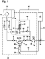
- FIG. 1 is a circuit diagram of a conveyor system for an operating material / auxiliary material with the essential assemblies.
- a conveying device for conveying an operating / auxiliary material for example a reducing agent such as a urea-water solution or urea, comprises a tank unit 10 in which the operating / auxiliary material is stored.
- a filter 14 On an intake line 12 there is a filter 14.
- a first ice pressure damper 16 is assigned to the suction line 12.
- the suction-side valve 18 is accommodated in a valve assembly 22 together with a pressure-side valve 32, which is also designed as a spring-loaded check valve.
- the valve assembly 22 delimits an element space 98, 100 see Figure 4 .
- the operating / auxiliary material flows into the element space 98, 100 after passage of the suction-side valve 18.
- the element space 98, 100 is acted upon by a conveyor membrane 24, which in turn is actuated by means of a solenoid 28 that can be energized.
- the solenoid 28 is controlled by a control unit 40 via a control line 42.
- the control unit 40 takes over the control of a metering module 38, via which the operating / auxiliary material in the in Figure 1 Exhaust tract of an internal combustion engine, not shown, is injected.
- the control unit 40 has the task of controlling a lifting magnet 81 via a further control line 42, via which a return pump 46 is actuated.
- the operating / auxiliary material flowing into the element space 98, 100 is compressed via the delivery membrane 24, which is actuated by the lifting magnet 28, so that a pressure is built up.
- the operating / auxiliary material flows into the metering line 36 and, viewed in the pumping direction 58, to a pressure pulsation damper 34.
- the pressure pulsation damper 34 is located in the metering line 36 directly in front of the metering module 38, via which the operating / auxiliary material is introduced into the exhaust tract of the internal combustion engine.
- Reference number 60 denotes a suction direction in which the delivery system, ie the metering line 36, the pressure pulsation damper 34 and the metering module 38 can be emptied in the suction mode.
- the operating material / auxiliary material stored in the components mentioned can be conveyed back into the tank unit 10 via the suckback pump 46 in the suckback mode directly via a suckback line 64.
- the suction pump 46 comprises an element space in which a suction conveyor diaphragm 54 is located, which in turn is actuated by a solenoid 81.
- the solenoid 81 is actuated via the control line 42 via the control unit 40.
- the return suction membrane 54 is by a compression spring 52 acted upon.
- the suction conveyor diaphragm 54 closes or opens a sealing seat 56.
- the first ice pressure damper 16 which is arranged in the suction line 12, can be used to absorb operating / auxiliary material which expands at a low outside temperature, the expansion of which is of the order of 10%.
- the suction-side valve 18 of the valve assembly 22 opens in the event of a resulting negative pressure in the element space 98, 100 and allows the operating / auxiliary material to flow into the element space 98, 100.
- air is first sucked in and compressed.
- the suction-side valve 18 itself is pressed back into its seat by means of a spring when the pressure is equalized and closes off the connection to the tank unit 10.
- the suction-side valve 18 When the pressure in the element space 98, 100 increases, the suction-side valve 18 is closed and the pressure-side valve 32 is opened. The entire stroke volume is compressed and conveyed out of the element space 98, 100 under pressure.
- the conveyor membrane 24 is supported by a sheet metal, so that the lowest possible deformation of the conveyor membrane 24 occurs with increasing pressure.
- the suction-side valve 18 and the pressure-side valve 32 are accommodated in the common valve assembly 22. This represents a link between a bellhousing 74 and the solenoid 28.
- gaseous medium can be taken up from the filter 14. This is detected on the basis of a current monitor and, in order to avoid damage, the entire operating / auxiliary material is sucked back into the tank unit 10 by actuating the return pump 46 via the second tank connection point, ie the branch point 44.
- This process which takes place in the suction mode, avoids the supply of gaseous media to the metering module 38. A considerable amount of air or gas in the hydraulic circuit would otherwise lead to a deviation in the pressure control.
- the branch point, ie the connection of the suction protection 44 is placed in such a way that the returned quantity can be conveyed back into the tank unit 10 bypassing the filter 14.
- the suction pump 46 shown conveys a defined amount of the operating / auxiliary material, ie the freezable reduction medium, back into the tank unit 10 when the vehicle is at a standstill in order to avoid possible freezing damage due to the expanding operating / auxiliary material on the components of the delivery system.
- an arrangement is selected in which the suction lifting magnet 81 moves a plunger armature with a suction extraction membrane 54 up and down by frequency control.
- the return suction conveyor membrane 54 lies on the sealing seat 56 and closes it off with sufficient sealing force against the prevailing operating pressure.
- a circumferential sealing lip is preferably provided on the return suction membrane 54. Because the sealing lip is provided on the suction conveyor membrane 54 and not on the sealing seat 56, an image in the material of the suction conveyor membrane 54 can be avoided, so that otherwise occurring leaks can be excluded in the longer term.
- the plunger anchor with the vulcanized-back suction conveyor membrane 54 is placed on the sealing seat 56 as shown in FIG Figure 1 pressed.
- the suction lifting magnet 81 is actuated from the control unit 40 by actuation via the control line 42, the plunger armature with the sucking back conveyor membrane 54 vulcanized thereon is lifted off the sealing seat 56. A negative pressure thus arises in the element space of the return pump 46. The negative pressure leads to the opening of the first valve 48, so that the operating / auxiliary material enters the return pump 46 in the suction direction 60.
- the first valve 48 comprises a sealing plate which is clamped on two connecting webs. This sealing plate is opened by the existing vacuum and the operating / auxiliary material, i.e. the freezable reduction medium can flow out.
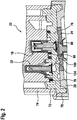
- the delivery device with valve assembly 22 can be seen in the installed state, which comprises a pressure-side and a suction-side valve.
- FIG. 2 shows that the valve assembly 22 is essentially represented by a mounting plate 76, in which the suction-side valve 18 and the pressure-side valve 32 are embedded.
- the receiving plate 76 of the valve assembly 22 has a first connection surface 70 and a second connection surface 72 on its outside. Along the first connection surface 70 there is a material connection of the mounting plate 76 of the valve assembly 22 to the lifting magnet 28, while the second connection surface 72 provides a material connection to a bellhousing 74.
- the receiving plate 76 thus acts as a link between the pump support 74 and the lifting magnet 28, via which the delivery membrane 24 is actuated.
- Circumferential relaxation-free laser weld seams are preferably formed on the first connection surface 70 and the second connection surface 72, which exclude a relative movement of the pump support 74 with respect to the lifting magnet 28.
- the representation goes from Figure 2 shows that the pressure-side valve 32 is surrounded by a first sealing ring 78, while a valve collar in the mounting plate 76 on the suction-side valve 18 is surrounded by a second sealing ring 80 made of elastic material.
- the two sealing rings 78, 80 are each embedded in corresponding circumferential grooves, which are located on the upper plane side of the mounting plate 76 of the valve assembly 22.
- the mounting plate 76 of the valve assembly 22 is sealed against the bellhousing 74 via the two sealing rings 78, 80.
- the sealing rings 78, 80 for the pump support 74 are installed with pressure support. This means that the sealing rings 78, 80 are supported at high operating pressures both with regard to excess pressure and with regard to the negative pressure that occurs.
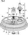
- FIG 3 shows an exploded view of the valve assembly of the delivery device according to the invention Figure 2 .
- Figure 3 shows that the mounting plate 76 of the valve assembly 22 on the outside comprises the first connection surface 70 and the second connection surface 72.
- the suction-side valve 18 comprises a suction-side sieve 90 and a spring with a retaining washer, cf. Position 88.
- a suction-side piston is designated by reference numeral 84 and comprises, at one end facing element space 98 or 100, a first valve plate 120 which is surrounded by a circumferential, flexible sealing lip 102.
- valve assembly 22 receives the components of the pressure-side valve 32.
- components include a cap-shaped guide element 92, on which a spring 96 is supported, which acts on the pressure-side piston 94.
- the pressure-side piston 94 comprises a second valve plate 122, which is likewise surrounded by a sealing lip 102 made of flexible material.
- Figure 3 also shows support points designated by reference numeral 82, which allow an exact support of the valve assembly 22 in alignment with the bellhousing 74 and the solenoid 28.
- the support points 82 also serve as reference points for the definition of flatness and parallelism Valve assembly 22 in relation to the adjacent components, said pump bracket 74 and said lifting magnet 28, with which the delivery membrane 24 is actuated.
- Figure 4 shows an enlarged view of the valve assembly in the installed state.
- FIG. 4 it can be seen that the mounting plate 76 of the valve assembly 22 forms the element space 98. Extending from the element space 98 through the receiving plate 96, a connecting channel 100 to the second valve plate 122 of the pressure-side piston 94 of the pressure-side valve 32. The element space 98 is delimited on its underside by the delivery membrane 24. The delivery membrane 24 is in turn actuated by the solenoid 28, not shown here. To reduce the deformation of the conveyor membrane 24 during strokes, this is supported by a sheet or the like in order to limit the deformation of the conveyor membrane 24 during operation.
- the holding disk 88 is supported on the spring acting on the suction-side piston 84 on the ceiling of the suction-side screen 90.
- the first valve plate 120 of the suction-side piston 84 is surrounded by the flexible sealing lip 102.
- the receiving plate 76 of the valve assembly 22 there is a piston stop 106 which limits the movement and thus the delivery stroke of the suction-side piston 84.
- the first valve plate 120 projects into the element space 98.
- the element space 98 is minimized in terms of its dead volume.
- the dead volume is the volume within a compression space that cannot be displaced.
- the dead volume remains after each stroke and prevents complete compression of the gaseous medium. This in turn results in a reduction in the opening pressure that can be generated. It is therefore important to minimize the dead volume.
- the connecting channel 100 extends from the element space 98 in the direction of the second valve plate 122 of the pressure-side valve 32, which is likewise surrounded by a flexible sealing lip 102.
- Reference number 118 denotes a sealing diameter.
- the sealing diameter 118 is the diameter influencing the opening pressure of the pressure-side valve 32. According to the representation Figure 4 the diameter 118 is somewhat reduced in relation to the flexible sealing lip 102.
- the seal between the pump support 94 and the mounting plate 76 of the valve assembly 22 is provided by the sealing rings 78 and 80, respectively. These lie in correspondingly circumferential grooves, supported by in Figure 4 Support ribs 116, not shown, which ensure the dimensional stability of the annular sealing rings 78, 80 in the event of the occurrence of negative pressure.
- the force exerted on the pistons 84, 94 by the springs 96 and 88 builds up a sufficient surface pressure in order to prevent an internal tank pressure of the operating / auxiliary material stored in the tank unit 10 as well as a possible vehicle misalignment, leakage and an associated flooding of the lines can cause.
- FIG. 4 it can also be seen that the piston 94 of the pressure-side valve 32 is guided in a cap-shaped guide element 92.
- This cap-shaped guide element 92 is cohesively connected in particular to the pump support 94, so that a precise alignment with regard to the perpendicularity and a concomitant precise guidance of the pressure-side piston 94 of the pressure-side valve 32 can be achieved.
- the cap-shaped element 92 also serves to support the spring 96.
- Figure 5 shows a sectional view through the pressure-side valve of the valve assembly of the conveyor device according to the invention.
- Figure 5 shows that the pressure-side piston 94 in the cap-shaped guide element 92 to support the right-angled guide, ie a low-friction guide, is connected to the pump carrier 74, in particular is integrally connected to it, for example welded.
- the spring 76 which acts on the second valve plate 122 of the pressure-side piston 94, is supported in the cap-shaped guide element 92.
- a centering collar 110 positions the cap-shaped guide element 92 relative to the receiving plate 76 and thus increases the Rectangularity specification, ie defines the position in which the cap-shaped guide element 92 is integrally connected to the bellhousing 94.
- FIG. 5 it can also be seen that the flexible sealing lip 102 surrounds the second valve plate 122 of the pressure-side piston 94 and, because of its flexibility, covers all unevenness that occurs and thus allows air to be sucked in and minimizes the outflow of small quantities during the conveying operation.
- a defined closing time of the pressure-side valve 32 is given by said spring 96, which acts on the pressure-side piston 94 of the pressure-side valve 32, so that a loss of quantity in the conveying operation can be minimized.
- valve plate According to the presentation Figure 6.1 the view of a valve plate can be seen, which assigns to the element space.
- Figure 6.1 shows that the second valve plate 122 comprises a roughened area 112 using the example of the pressure-side piston 94.
- the roughened area 112 on the underside of the second valve plate 122 is surrounded by the sealing lip 102 made of flexible material.
- the influencing diameter ie the sealing diameter identified with reference number 118. Due to the setting behavior of the flexible sealing lip 102 in relation to the diameter of the connecting channel 100, the influencing diameter, ie the sealing diameter 118, can be reduced, which would result in an increase in the opening pressure at the pressure valve 32.
- a channel geometry 126 is used, compare illustration according to Figure 6.2 , is provided, through which the medium, ie in the present case the operating / auxiliary material can be transported up to the influencing diameter, ie to the diameter 118.
- Figure 6.2 shows the course of the channel geometry 126 in the surface of the second valve plate 122 on the pressure valve 32 of the valve assembly 22. Also in FIG Figure 6.2 the influencing diameter, ie the sealing diameter, is indicated with reference number 118. This lies in the area of the material of the flexible sealing lip 102.
- Figure 7 shows the configuration of a guide geometry of the receiving plate of the conveyor with valve assembly for guiding a suction-side piston.
- the guide of the suction-side piston 84 of the suction-side valve 18 can be designed with a particularly low friction by a guide geometry 104.
- a guide geometry 104 is provided which, for example, comprises a number of guide ribs.
- the guide ribs can be designed in a 90 ° division or a 120 ° division, surrounding the outer surface of the suction-side piston 84, so that it is guided with very little friction.
- the guide geometry 104 forms a flow cross-section 114 with the piston 84 on the suction side, in particular its outer surface and the first valve plate 120 facing the element chamber 98, which the operating / auxiliary material passes through when the intake valve 18 is open.
- Figure 8 shows that the pressure-side valve 32 includes the cap-shaped guide element 92, which can be connected to the pump support 74 in a materially integral manner.
- the spring 96 is supported on this, which in turn acts on the pressure-side piston 94 hidden by the cap-shaped guide element 92.
- On the collar-shaped geometry which is formed in the area of the receptacle of the pressure-side valve 32 in the receptacle plate 76, support ribs 116 protrude in the radial direction. In the event of suppression, these support ribs 116, which extend in the radial direction, serve the sealing element 78 to keep in shape.
- the second sealing element 80 which is located on the suction-side valve and is likewise accommodated there in a groove running around a collar-shaped extension.
- a dead volume can be greatly reduced by the valve assembly 22, so that suction of gaseous media can be represented.
- An influencing diameter 118 in relation to the opening pressure is defined by the different surface properties of the valve plates, in particular of a roughened area 112.
- the flexible sealing lips 102 which are located on the circumference of the valve plates 120, 122, cover all unevenness on the mounting plate 76 that occurs due to production or assembly and thus enable air to be sucked in and small quantities to escape during the conveying operation.
- the use of the compression springs 88, 96 advantageously provides a definition of the closing times of the intake and pressure-side valves 18 and 32, so that a loss of quantity in the conveying operation is minimized.
- the volume of the element space can advantageously be defined by the element space rib 108, so that the dynamic area can be separated from the statically sealing area.
- the sealing rings 78 and 80 are centered in a secure position, it is for avoidance taken care of by relative movements during swelling pressure states in the element space 98, 100.
- the mounting plate 76 of the valve assembly 22 serves as a link between the bellhousing 74 and the lifting magnet 28.
- the rib arrangement of the guide geometry 104 significantly reduces the frictional resistance when the pistons 84, 94 are guided.
- the cap-shaped guide element 92 which is preferably integrally connected to the receiving plate 76, defines the perpendicularity of the guide axis at least of the suction-side piston 84 with respect to the sealing surface.
Landscapes
- Engineering & Computer Science (AREA)
- General Engineering & Computer Science (AREA)
- Mechanical Engineering (AREA)
- Reciprocating Pumps (AREA)
- Details Of Reciprocating Pumps (AREA)
Description
-
DE 10 2012 211 875 betrifft ein Fördermodul für einen Betriebs-/ Hilfsstoff zur Nachbehandlung von Abgas. Es wird eine Einrichtung zur Förderung eines flüssigen Mediums vorgeschlagen, wobei das flüssige Medium Gas-/Luft- oder Dampfanteile enthält. Die Einrichtung fördert das flüssige Medium im Pumpenmodus in eine Pumprichtung und im Rücksaugmodus in eine Rücksaugrichtung. Eine Ansteuereinrichtung betätigt im Fördermodus in Pumprichtung einen Hubmagneten einer Fördermembran und im Rücksaugmodus in Rücksaugrichtung einen Rücksaugpumpenmagneten einer Rücksaugfördermembran. Die Drucküberwachung erfolgt über eine Auswertung der Stromverläufe von Magneten in einer Ansteuereinrichtung. -
US 3,354,830 bezieht sich auf eine Membranförderpumpe zum Pumpen eines aromaverleihenden Sirups und anderer Flüssigkeiten, die einen variablen Hub aufweist. Dies wird durch eine Variation der Kolbenverdrängung erreicht. Die Membranförderpumpe umfasst Steuerventile, die austauschbar im Pumpengehäuse angeordnet sind, die mit einer Vakuumkammer verbunden sind, sodass eine einfache Reinigung und Reparatur ermöglicht wird. -
US 5,226,445 bezieht sich auf ein Ventil mit einer konvexen Dichtfläche und einer konkaven Ventilsitzfläche. Die Dichtfläche ist konvex gestaltet und ermöglicht eine konvexe Diskontinuität in eine sich axial erstreckende Richtung. Die Dichtfläche entspricht näherungsweise demselben Betrag einer Kontaktfläche mit der Sitzfläche bei nicht ausgerichtetem Kolben. - Erfindungsgemäß wird eine Fördereinrichtung zum Eindosieren eines Betriebs-/Hilfsstoffs in einen Abgastrakt einer Verbrennungskraftmaschine mit einer Ventilbaugruppe vorgeschlagen, mit einem ansaugseitigem Ventil und einem druckseitigen Ventil, die jeweils federbeaufschlagte Kolben aufweisen, wobei die Kolben jeweils flexible Dichtlippen aufweisen und einen durch eine Fördermembran beaufschlagbaren Elementenraum begrenzen, durch den der Betriebs-/Hilfsstoff gefördert wird, wobei die Dichtlippen an Ventiltellern der Kolben einen aufgerauten Bereich umschließen.
- Die erfindungsgemäß vorgeschlagene Fördereinrichtung mit Ventilbaugruppe nimmt das ansaugseitige Ventil und das druckseitige Ventil auf und begrenzt den Elementenraum. Die Ventilbaugruppe stellt eine Teilkomponente der Fördereinrichtung dar und wird direkt auf einem Aktor, der im vorliegenden Fall bevorzugt als Hubmagnet ausgebildet ist, angeordnet. Die Ventilbaugruppe beinhaltet sämtliche Komponenten des ansaugseitigen Ventils und des druckseitigen Ventils einschließlich von Druckfedern. Die Aufnahmeplatte der Ventilbaugruppe stellt ein Bindeglied zwischen einem Pumpträger und besagtem Hubmagneten dar und verhindert eine Relativbewegung zwischen diesen Komponenten, die sich auf die Förderkennlinie negativ auswirken würde. Die Ventilbaugruppe, insbesondere die Zwischenplatte, welche die Komponenten des ansaugseitigen Ventils sowie des druckseitigen Ventils aufnimmt, ist in vorteilhafter Weise mit zwei stoffschlüssigen Verbindungsnähten mit dem Hubmagneten einerseits und dem Pumpenträger anderseits relaxationsfrei verbunden.
- In vorteilhafter Weise sind die in der Aufnahmeplatte der Ventilbaugruppe angeordneten ansaugseitigen und druckseitigen Ventile druckfederbeaufschlagt und werden in die jeweiligen Dichtsitze gedrückt. Dies bietet den Vorteil, dass die Ventile bei zunehmender Druckstärke abdichten.
- Mit Hilfe der erfindungsgemäß vorgeschlagenen Fördereinrichtung mit Ventilbaugruppe, insbesondere der Aufnahmeplatte, ist es möglich, eine Dosierpumpe, beziehungsweise eine Fördereinrichtung darzustellen, die auf einen Drucksensor verzichtet. Durch die erfindungsgemäß vorgeschlagene Fördereinrichtung und die darin aufgenommenen ansaugseitigen und druckseitigen Ventile kann eine exakte Fördermenge im Fördersystem zugeführt werden. Eine exakte Ausrichtung der Ventilbaugruppe zum Pumpenträger einerseits sowie zum Hubmagneten andererseits wird mittels beispielsweise dreier Auflagepunkte definiert, die gleichzeitig als Referenzpunkte dienen und die Ebenheit und Parallelität der Ventilbaugruppe zu den angrenzenden Bauteilen d.h. dem Pumpenträger und dem Hubmagneten festlegen.
- Die Federkraft der Federn, mit denen die Kolben des ansaugseitigen Ventils sowie des druckseitigen Ventils beaufschlagt sind, ermöglicht eine ausreichende Flächenpressung um zu verhindern, dass beispielsweise der Innendruck einer Tankeinheit zur Bevorratung des Betriebs-/Hilfsstoffes sowie eine mögliche Fahrzeugschiefstellung, eine Leckage und eine damit einhergehende Flutung der Leitungen auftritt. Insbesondere kann das druckseitige Ventil in einem kappenförmig ausgebildeten Führungselement geführt werden, sodass eine Verkantung bei dessen Bewegung durch präzise Ausrichtung verhindert wird. Das kappenförmige Element, insbesondere des druckseitigen Ventils der Ventilbaugruppe dient ferner als Abstützung der Feder des druckseitigen Ventils. Mittels eines Zentrierkragens wird das kappenförmig ausgebildete Führungselement relativ zur Aufnahmeplatte der Ventilbaugruppe positioniert, sodass die Rechtwinkligkeitsvorgabe eingehalten werden kann. Insbesondere ist das druckseitige Ventil, beziehungsweise dessen Ventilteller, der von einer flexiblen Dichtlippe umrahmt wird, bis zur Dichtsitzgeometrie mit einer grobstrukturierten angerauten Oberfläche ausgeführt, sodass bei Druckverformungen des elastischen Elementes keine Öffnungsdurchmesserveränderung auftritt.
- Beim ansaugseitigen Ventil, welches ebenfalls in der Aufnahmeplatte der Ventilbaugruppe angeordnet ist, ist in vorteilhafter Weise dafür Sorge getragen, dass sich der Ventilteller des saugseitigen Kolbens beim Öffnen in den Elementenraum hineinbewegt und einen Durchflussquerschnitt freigibt. Durch diese Anordnungsweise wird das Totvolumen minimiert. Beim Totvolumen handelt es sich um ein Volumen, welches noch mit Medium gefüllt ist, sobald die Fördermembrane, die durch den Hubmagneten bewegt wird und den Elementenraum von der Unterseite her begrenzt ihren oberen Totpunkt erreicht. Ziel der erfindungsgemäß vorgeschlagenen Lösung ist es, mit einem möglichst geringen Totvolumen einen Kompressionsdruck so weit zu erhöhen, dass auch bei einem kleinen Hub der Fördermembran Luft angesaugt werden kann. Im Weiteren sind beide Ventile mit einer speziellen Plasmabeschichtung versehen, die ein Anhaften des mit Elastomer benetzten Kolbens zu der aus Thermoplast bestehenden Aufnahmeplatte verhindern soll. Dadurch ist die Erstbefüllung des Gesamtsystems gewährleistet. Unterbliebe eine derartige Beschichtung, erhöhte sich der Öffnungsdruck so weit, dass der Kompressionsdruck mit Luft oder anderen Gasen nicht ausreicht, um die Ventile zu öffnen.
- In einer weiteren vorteilhaften Ausgestaltung des der Erfindung zugrunde liegenden Gedankens ist beispielsweise der Kolben des saugseitigen Ventils durch eine Führungsgeometrie geführt, um zum einen den notwendigen Strömungsquerschnitt zur Passage des Betriebs-/Hilfsstoffes darzustellen und zum anderen die Verschmutzungsanfälligkeit zu verringern und ein mit zunehmender Verschmutzung möglicherweise auftretendes Klemmen zu vermeiden.
- Des Weiteren weist die Aufnahmeplatte der Ventilbaugruppe im Bereich der Aufnahmeöffnung, beziehungsweise des Aufnahmekragens für das ansaugseitige Ventil und das druckseitige Ventil, umlaufende Nuten auf, in welche zwei Axialformdichtungen, insbesondere ausgestaltet als O-Ringe, eingelegt werden. Beide Dichtungen werden druckunterstützend eingebaut, d.h. bei den beiden Axialformdichtungen erfolgt bei höheren Betriebsdrücken sowohl hinsichtlich Überdruck als auch Unterdrück eine in Radialrichtung wirkende Abstützung. Eine Überdruckabsicherung erfolgt über die Durchmesser, an denen die Axialformdichtungen anliegen. Die Unterstützung bei Unterdrück erfolgt mittels am Umfang angeordneter Rippen. Diese Anordnung der Axial-Formdichtungen in die Aufnahmeplatte eingeformte Nuten sichert einerseits die Abstützung und zum anderen wird durch die verbleibenden Zwischenräume sichergestellt, dass genügend Raum für Quellung und Temperaturgang der aus elastischem Material gefertigten Axialformdichtungen zur Verfügung steht.
- Die erfindungsgemäß vorgeschlagene Fördereinrichtung zeichnet sich dadurch aus, dass durch die Ventilbaugruppe und die in dieser angeordneten ansaugseitigen und druckseitigen Ventile das Totvolumen stark reduziert wird, sodass ein Ansaugen von gasförmigen Medien dargestellt werden kann. Das Ansaugen gasförmiger Medien wie beispielsweise Luft ist wichtig, um die Erstbefüllung zu gewährleisten. Nach Komplettmontage des Systems und Befüllung des Vorratstanks ist die Pumpe noch nicht mit Medium befüllt. Dies bedeutet, dass die Pumpe zunächst eine Luft- oder Gasmenge fördern muss, bis der Betriebs-/Hilfsstoff, d.h. das Reduktionsmittel an die Ventile gelangt.
- Aufgrund der unterschiedlichen Oberflächenbeschaffenheit der Ventilteller, die an den dem Elementenraum zuweisenden Enden der Kolben des ansaugseitigen und des druckseitigen Ventils angeordnet sind, wird ein einflussnehmender Durchmesser auf den Öffnungsdruck definiert. Die Ventilteller sind in vorteilhafter weise von flexiblen Dichtlippen umrandet, die alle fertigungsbedingt möglicherweise auftretenden Unebenheiten abdecken und das Ansaugen von Luft einerseits ermöglichen und andererseits das Austreten von Mindermengen während des Pumpbetriebes verhindern, sodass eine Fördermengenabweichung im Gegensatz zu aus dem Stand der Technik bekannten Lösungen sicher ausgeschlossen werden kann.
- Sowohl das ansaugseitige wie auch das druckseitige Ventil der Ventilbaugruppe sind federbeaufschlagt ausgebildet, sodass die Schließzeit der Ventile definiert ist, um einen Mengenverlust beim Förderbetrieb zu minimieren.
- Durch die erfindungsgemäß vorgeschlagene Lösung werden Lagezentrierungen der Axial-Formdichtungen geschaffen, sodass Relativbewegungen während schwellender Druckzustände innerhalb des Elementenraums beim Förderbetrieb vermieden werden. Um sicherzustellen, dass eine Relativbewegung der Ventilbaugruppe im Druckbetrieb vermieden wird, stellt die Aufnahmeplatte das Bindeglied zwischen dem Pumpenträger und dem Hubmagneten dar, mit welchem sie jeweils über stoffschlüssig ausgebildete Verbindungen relaxationsfrei verbunden wird.
- Durch die in den Elementenraum hineinragende Elementenraumrippe wird dessen Volumen wohl definiert, so dass Quell- und Temperatureinflüsse der Fördermembran keinen Einfluss auf das Volumen des Elementenraumes haben. Dadurch wird ein Durchmesser definiert, der über die Lebensdauer konstant bleibt. Des Weiteren kann in den vom Elementenraum abzweigenden Verbindungskanal eine Drossel vorgesehen werden, die in vorteilhafter Weise als Durchmesserverengung gefertigt werden kann. Die Drossel dient der Reduktion von Geräuschemissionen und stellt eine hydraulische Beeinflussung des Strömungsquerschnittes dar. Dadurch wird die Geschwindigkeit des Hubmagneten beeinflusst und somit die Auftreffgeschwindigkeit desselben verlangsamt. Dadurch wiederum kann in vorteilhafter Weise erreicht werden, dass die Lautstärke beim Betrieb des Fördermoduls verringert wird.
- Beim druckseitigen Ventil der Ventilbaugruppe kann in vorteilhafter Weise eine Kanalgeometrie geschaffen werden, so dass ein Setzen des druckseitigen Kolbens vermieden wird. Durch diese Geometrie ist beim druckbelastenden der beiden Ventile der Ventilbaugruppe der Wirkdurchmesser stets offen.
- Anhand der Zeichnungen wird die Erfindung nachstehend eingehender beschrieben.
- Es zeigt:
- Figur 1
- ein Schaltbild eines Fördersystems zwischen Tankeinheit und einem Dosiermodul,
- Figur 2
- eine Darstellung der Fördereinrichtung mit Ventilbaugruppe mit ansaugseitigem und druckseitigem Ventil,
- Figur 3
- eine Explosionsdarstellung der Ventilbaugruppe gemäß der Darstellung in
Figur 2 , - Figur 4
- die Darstellung des ansaugseitigen und des druckseitigen Ventils im Schnitt,
- Figur 5
- eine Darstellung des druckseitigen Ventils,
- Figur 6.1
- eine Ansicht des Ventiltellers des druckseitigen Kolbens,
- Figur 6.2
- die Darstellung einer Kanalgeometrie am Ventilteller des druckseitigen Kolbens,
- Figur 7
- eine perspektivische Draufsicht auf die Führungsgeometrie des Kolbens des ansaugseitigen Ventils der Ventilbaugruppe und
- Figur 8
- die Darstellung eines kappenförmig ausgebildeten Führungselements zur Darstellung einer im Wesentlichen rechtwinkligen Führung des entsprechenden Kolbens des druckseitigen Ventils.
- Der Darstellung gemäß
Figur 1 ist ein Schaltbild eines Fördersystems für einen Betriebs-/Hilfsstoff mit den wesentlichen Baugruppen zu entnehmen. - Eine Fördereinrichtung zur Förderung eines Betriebs-/Hilfsstoffes, beispielsweise eines Reduktionsmittels wie einer Harnstoff-Wasserlösung oder Harnstoff, umfasst eine Tankeinheit 10, in der der Betriebs-/Hilfsstoff bevorratet ist. An einer Ansaugleitung 12 befindet sich ein Filter 14. Der Ansaugleitung 12 ist des Weiteren ein erster Eisdruckdämpfer 16 zugeordnet. In der Ansaugleitung 12 befindet sich ein Ansaugventil 18, das als ein federbeaufschlagtes Rückschlagventil ausgeführt ist. Das ansaugseitige Ventil 18 ist zusammen mit einem ebenfalls als federbeaufschlagtes Rückschlagventil gestalteten druckseitigen Ventil 32 in einer Ventilbaugruppe 22 aufgenommen. Die Ventilbaugruppe 22 begrenzt einen Elementenraum 98, 100 siehe
Figur 4 . Dem Elementenraum 98, 100 strömt der Betriebs-/Hilfsstoff nach Passage des ansaugseitigen Ventiles 18 zu. Der Elementenraum 98,100 ist durch eine Fördermembran 24 beaufschlagt, die ihrerseits mittels eines bestrombaren Hubmagneten 28 betätigt wird. Der Hubmagnet 28 wird durch eine Ansteuereinheit 40 über eine Ansteuerleitung 42 angesteuert. Des Weiteren übernimmt die Ansteuereinheit 40 die Ansteuerung eines Dosiermodules 38, über welches der Betriebs-/Hilfsstoff in den inFigur 1 nicht näher dargestellten Abgastrakt einer Verbrennungskraftmaschine eingespritzt wird. Darüber hinaus hat die Ansteuereinheit 40 die Aufgabe, über eine weitere Ansteuerleitung 42 einen Hubmagneten 81 anzusteuern, über den eine Rücksaugpumpe 46 betätigt wird. Der in den Elementenraum 98,100 einströmende Betriebs-/Hilfsstoff wird über die durch den Hubmagneten 28 betätigte Fördermembran 24 verdichtet, sodass ein Druck aufgebaut wird. Bei Überschreiten des Öffnungsdruckes des druckseitigen Ventiles 32 strömt der Betriebs-/Hilfsstoff in die Dosierleitung 36 ein und in Pumprichtung 58 gesehen, einem Druckpulsationsdämpfer 34 zu. Der Druckpulsationsdämpfer 34 befindet sich in der Dosierleitung 36 unmittelbar vor dem Dosiermodul 38, über welches der Betriebs-/Hilfsstoff in den Abgastrakt der Verbrennungskraftmaschine eingebracht wird. - Wie aus der Darstellung gemäß
Figur 1 hervorgeht, befindet sich zwischen der Auslassseite des druckseitigen Ventiles 32 und dem Druckpulsationsdämpfer 34 eine Abzweigstelle 44 eines Rücksaugstutzens, der sich zur Rücksaugpumpe 46 erstreckt. Diese umfasst ein erstes Ventil 48, ferner ein zweites Ventil 50, die analog zum ansaugseitigen Ventil 18 und zum druckseitigen Ventil 32 als federbeaufschlagte Rückschlagventile ausgebildet werden können. Mit Bezugszeichen 60 ist eine Rücksaugrichtung bezeichnet, in welche das Fördersystem, d.h. die Dosierleitung 36, der Druckpulsationsdämpfer 34 und das Dosiermodul 38 im Rücksaugmodus entleert werden können. Der in den erwähnten Komponenten bevorratete Betriebs-/Hilfsstoff kann über die Rücksaugpumpe 46 im Rücksaugmodus unmittelbar über eine Rücksaugleitung 64 wieder in die Tankeinheit 10 zurückgefördert werden. - Wie die Darstellung gemäß
Figur 1 weiter zeigt, umfasst die Rücksaugpumpe 46 einen Elementenraum, in dem sich eine Rücksaugfördermembran 54 befindet, die ihrerseits durch einen Hubmagneten 81 betätigt wird. Der Hubmagnet 81 wird via Ansteuerleitung 42 über die Ansteuereinheit 40 betätigt. Die Rücksaugfördermembran 54 ist durch eine Druckfeder 52 beaufschlagt. Die Rücksaugfördermembran 54 schließt oder öffnet einen Dichtsitz 56. Bei Betätigung der Rücksaugpumpe 46 im Rücksaugmodus strömt bei geöffnetem Dichtsitz 56 der rückgesaugte Betriebs-/Hilfsstoff über die zweite Abzweigstelle 44 dem Rücksaugstutzen zu, über das erste Ventil 48 in den Elementenraum 98,100, über das zweite Ventil 50 in die Rücksaugleitung 46 und von dort unter Umgehung des Filters 14 direkt zurück in die Tankeinheit 10. - Über den ersten Eisdruckdämpfer 16, der in der Ansaugleitung 12 angeordnet ist, kann sich bei tiefer Außentemperatur ausdehnender Betriebs-/Hilfsstoff, dessen Ausdehnung in der Größenordnung von 10% liegt, aufgenommen werden. Das ansaugseitige Ventil 18 der Ventilbaugruppe 22 öffnet im Falle eines sich ergebenden Unterdruckes im Elementenraum 98, 100 und lässt den Betriebs-/Hilfsstoff in den Elementenraum 98, 100 einströmen. Im Falle eines noch nicht befüllten Filters 14 beziehungsweise Fördermodules 20 wird zunächst Luft angesaugt und komprimiert. Das ansaugseitige Ventil 18 selbst wird mittels einer Feder bei Druckausgleich zurück in seinen Sitz gedrückt und schließt die Verbindung zur Tankeinheit 10 ab. Bei Druckerhöhung im Elementenraum 98, 100 wird das saugseitige Ventil 18 geschlossen und das druckseitige Ventil 32 geöffnet. Das komplette Hubvolumen wird komprimiert und aus dem Elementenraum 98, 100 unter Druck hinausgefördert. Die Fördermembran 24 wird durch ein Blech unterstützt, sodass bei zunehmendem Druck eine möglichst geringe Verformung der Fördermembran 24 auftritt. Das ansaugseitige Ventil 18 und das druckseitige Ventil 32 sind in der gemeinsamen Ventilbaugruppe 22 aufgenommen. Diese stellt ein Bindeglied zwischen einem Pumpenträger 74 und dem Hubmagneten 28 dar.
- Im Fördermodus des Fördermoduls 20 kann gasförmiges Medium aus dem Filter 14 aufgenommen werden. Dies wird anhand einer Stromüberwachung detektiert und zur Vermeidung von Schäden der gesamte Betriebs-/Hilfsstoff mittels Betätigung der Rücksaugpumpe 46 über die zweite Tankanbindungsstelle, d.h. die Abzweigstelle 44 in die Tankeinheit 10 rückgesaugt. Dieser im Rücksaugmodus stattfindende Vorgang vermeidet die Zuführung gasförmiger Medien zum Dosiermodul 38. Ein erheblicher Luft- bzw. Gasanteil im Hydraulikkreis würde ansonsten zu einer Abweichung hinsichtlich der Drucksteuerung führen. Die Abzweigstelle, d.h. der Anschluss des Rücksaugschutzes 44 ist so platziert, dass die zurückgeführte Menge unter Umgehung des Filters 14 unmittelbar in die Tankeinheit 10 zurückgefördert werden kann. Die in
Figur 1 dargestellte Rücksaugpumpe 46 fördert bei Stillstand des Fahrzeugs eine definierte Menge des Betriebs- /Hilfsstoffes, d.h. des gefrierfähigen Reduktionsmediums zurück in die Tankeinheit 10, um mögliche Gefrierschädigung aufgrund des sich ausdehnenden Betriebs-/Hilfsstoffes an den Komponenten des Fördersystems zu vermeiden. Um dies zu gewährleisten, wird eine Anordnung gewählt, bei der der Rücksaughubmagnet 81 durch eine Frequenzansteuerung einen Tauchanker mit Rücksaugfördermembran 54 auf- und ab bewegt. Im nicht betätigten Zustand liegt die Rücksaugfördermembran 54 auf dem Dichtsitz 56 und schließt diesen mit ausreichender Dichtkraft gegen den anstehenden Betriebsdruck ab. Vorzugsweise ist eine umlaufende Dichtlippe an der Rücksaugfördermembran 54 vorgesehen. Dadurch, dass die Dichtlippe an der Rücksaugfördermembran 54 vorgesehen ist und nicht am Dichtsitz 56, kann ein Abbild im Werkstoff der Rücksaugfördermembran 54 vermieden werden, sodass sich andernfalls auf längere Sicht einstellende Leckagen ausgeschlossen werden können. - Mittels der Druckfeder 52 wird der Tauchanker mit aufvulkanisierter Rücksaugfördermembran 54 auf den Dichtsitz 56 gemäß der Darstellung in
Figur 1 gedrückt. - Wird der Rücksaughubmagnet 81 durch Ansteuerung via Ansteuerleitung 42 von der Ansteuereinheit 40 aus betätigt, wird der Tauchanker mit daran anvulkanisierter Rücksaugfördermembran 54 vom Dichtsitz 56 abgehoben. Im Elementenraum der Rücksaugpumpe 46 entsteht somit ein Unterdrück. Der Unterdrück führt zur Öffnung des ersten Ventiles 48, sodass der Betriebs-/Hilfsstoff in Saugrichtung 60 in die Rücksaugpumpe 46 eintritt. Das erste Ventil 48 umfasst ein Dichtplättchen, welches an zwei Anbindungsstegen eingespannt ist. Durch den anstehenden Unterdrück wird dieses Dichtplättchen geöffnet und der Betriebs-/Hilfsstoff, d.h. das gefrierfähige Reduktionsmedium, kann abströmen.
- Der Darstellung gemäß
Figur 2 ist die Fördereinrichtung mit Ventilbaugruppe 22 im eingebauten Zustand zu entnehmen, die ein druckseitiges und ein ansaugseitiges Ventil umfasst. -
Figur 2 zeigt, dass die Ventilbaugruppe 22 im Wesentlichen durch eine Aufnahmeplatte 76 dargestellt ist, in welcher das ansaugseitige Ventil 18 und das druckseitige Ventil 32 eingelassen sind. Die Aufnahmeplatte 76 der Ventilbaugruppe 22 weist an ihrer Außenseite eine erste Anbindungsfläche 70 und eine zweite Anbindungsfläche 72 auf. Entlang der ersten Anbindungsfläche 70 erfolgt eine stoffschlüssige Verbindung der Aufnahmeplatte 76 der Ventilbaugruppe 22 an den Hubmagneten 28, während durch die zweiten Anbindungsfläche 72 eine stoffschlüssige Verbindung zu einem Pumpenträger 74 gegeben ist. Die Aufnahmeplatte 76 wirkt somit als Bindeglied zwischen dem Pumpenträger 74 und dem Hubmagneten 28, über den die Fördermembran 24 betätigt ist. An der ersten Anbindungsfläche 70 und der zweiten Anbindungsfläche 72 werden bevorzugt umlaufende relaxationsfreie Laserschweißnähte ausgebildet, die eine Relativbewegung des Pumpenträgers 74 in Bezug auf den Hubmagneten 28 ausschließen. - Des Weiteren geht aus der Darstellung gemäß
Figur 2 hervor, dass das druckseitige Ventil 32 von einem ersten Dichtring 78 umgeben ist, während ein Ventilkragen in der Aufnahmeplatte 76 am ansaugseitigen Ventil 18 von einem zweiten, aus elastischem Material gefertigten Dichtring 80 umgeben ist. Die beiden Dichtringe 78, 80 sind jeweils in entsprechende umlaufende Nuten, die sich an der oberen Planseite der Aufnahmeplatte 76 der Ventilbaugruppe 22 befinden, eingelassen. Über die beiden Dichtringe 78, 80 ist die Aufnahmeplatte 76 der Ventilbaugruppe 22 gegen den Pumpenträger 74 abgedichtet. In bevorzugter Ausgestaltung werden die Dichtringe 78, 80 zum Pumpenträger 74 druckunterstützt eingebaut. Dies bedeutet, dass bei hohen Betriebsdrücken sowohl hinsichtlich Überdruck als auch hinsichtlich auftretendem Unterdrück eine Abstützung der Dichtringe 78, 80 erfolgt. Eine Überdruckabsicherung erfolgt über die Durchmesser, an denen die Dichtringe 78, 80 anliegen. Die Unterdruckfähigkeit der beiden Dichtringe 78, 80 ist dadurch gegeben, dass am Umfang der Kragen in der Zwischenplatte 76 Unterstützungsrippen 116 vgl. Darstellung gemäßFigur 8 , die in radiale Richtung wirken, ausgebildet sind. Diese Anordnung sichert zum einen die Abstützung der Dichtringe 78, 80 und zum anderen wird durch die Zwischenräume in den umlaufenden Nuten sichergestellt, dass genügend Raum für Quellung und Temperaturgang der Dichtringe 78, 80 bei entsprechenden Temperaturen vorliegt. -
Figur 3 zeigt eine Explosionsdarstellung der Ventilbaugruppe der erfindungsgemäßen Fördereinrichtung gemäßFigur 2 .Figur 3 zeigt, dass die Aufnahmeplatte 76 der Ventilbaugruppe 22 an der Außenseite die erste Anbindungsfläche 70 sowie die zweite Anbindungsfläche 72 umfasst. Zentrisch in der Aufnahmeplatte 76 befindet sich ein Aufnahmekragen 86 mit einem Sieb, in welchem das ansaugseitige Ventil 18 montiert wird. Das ansaugseitige Ventil 18 umfasst ein saugseitiges Sieb 90 sowie eine Feder mit Haltescheibe vgl. Position 88. Ein saugseitiger Kolben ist durch Bezugszeichen 84 bezeichnet und umfasst an einem dem Elementenraum 98 bzw. 100 zuweisenden Ende einen ersten Ventilteller 120, der durch eine umlaufende, flexible Dichtlippe 102 umrandet ist. - In gleicher Weise nimmt die Ventilbaugruppe 22, insbesondere die Aufnahmeplatte 76 die Komponenten des druckseitigen Ventiles 32 auf. Zu diesen Komponenten ist ein kappenförmiges Führungselement 92 zu zählen, an welchem sich eine Feder 96 abstützt, die den druckseitigen Kolben 94 beaufschlagt. Der druckseitige Kolben 94 umfasst einen zweiten Ventilteller 122, der ebenfalls von einer aus flexiblem Material gefertigten Dichtlippe 102 umrandet ist.
Figur 3 zeigt darüber hinaus mit Bezugszeichen 82 bezeichnete Auflagepunkte, die eine exakte Auflage der Ventilbaugruppe 22 in Ausrichtung zum Pumpenträger 74 und zum Hubmagneten 28 ermöglichen. Die Auflagepunkte 82 dienen gleichzeitig als Referenzpunkte zur Definition von Ebenheit und Parallelität der Ventilbaugruppe 22 in Bezug auf die angrenzenden Bauteile, besagtem Pumpenträger 74 und besagtem Hubmagneten 28, mit dem die Fördermembran 24 betätigt wird. -
Figur 4 zeigt eine vergrößerte Darstellung der Ventilbaugruppe im eingebauten Zustand. -
Figur 4 ist zu entnehmen, dass die Aufnahmeplatte 76 der Ventilbaugruppe 22 den Elementenraum 98 bildet. Vom Elementenraum 98 zweigt sich durch die Aufnahmeplatte 96 erstreckend, ein Verbindungskanal 100 zum zweiten Ventilteller 122 des druckseitigen Kolbens 94 des druckseitigen Ventiles 32. Der Elementenraum 98 ist an seiner Unterseite durch die Fördermembran 24 begrenzt. Die Fördermembran 24 wird ihrerseits durch den hier nicht näher dargestellten Hubmagneten 28 betätigt. Zur Verminderung der Deformation der Fördermembran 24 bei Hüben ist diese durch ein Blech oder dergleichen unterstützt, um die Deformation der Fördermembran 24 im Betrieb zu begrenzen. - Der Darstellung gemäß
Figur 4 ist des Weiteren zu entnehmen, dass sich die Haltescheibe 88 an der sich die den saugseitigen Kolben 84 beaufschlagende Feder abstützt an der Decke des saugseitigen Siebs 90 abstützt. Der erste Ventilteller 120 des saugseitigen Kolbens 84 ist von der flexiblen Dichtlippe 102 umrandet. In der Aufnahmeplatte 76 der Ventilbaugruppe 22 befindet sich ein Kolbenanschlag 106, welcher die Bewegung und damit den Förderhub des saugseitigen Kolbens 84 begrenzt. Wie ausFigur 4 hervorgeht, ragt der erste Ventilteller 120 in den Elementenraum 98 hinein. Der Elementenraum 98 ist hinsichtlich seines Totvolumens minimiert. Das Totvolumen ist das Volumen innerhalb eines Kompressionsraumes, das nicht verdrängt werden kann. Das Totvolumen bleibt nach Durchführung eines jeden Hubes übrig und verhindert eine vollständige Kompression gasförmigen Mediums. Daraus wiederum resultiert eine Verringerung des erzeugbaren Öffnungsdruckes. Daher ist die Minimierung des Totvolumens von Bedeutung. - Vom Elementenraum 98 aus erstreckt sich der Verbindungskanal 100 in Richtung auf den zweiten Ventilteller 122 des druckseitigen Ventils 32, der ebenfalls von einer flexiblen Dichtlippe 102 umrandet ist. Mit Bezugszeichen 118 ist ein Dichtdurchmesser bezeichnet. Der Dichtdurchmesser 118 ist der auf den Öffnungsdruck des druckseitigen Ventiles 32 einflussnehmende Durchmesser. In der Darstellung gemäß
Figur 4 liegt der Durchmesser 118 in Bezug auf die flexible Dichtlippe 102 etwas zurückgenommen. - Der Darstellung gemäß
Figur 4 lässt sich des Weiteren entnehmen, dass im Verbindungskanal 100, der sich vom Elementenraum 98 zum Druckventil 32 erstreckt, eine Querschnittsverengung 124 ausgebildet werden kann. Dadurch kann die Geschwindigkeit, mit welcher sich der Hubmagnet 28 bewegt, beeinflusst werden, so dass sich die Auftreffgeschwindigkeit des Hubmagneten 28 verringert und somit die Lautstärke der gesamten Fördereinheit im Betrieb positiv beeinflusst wird. - Der Darstellung gemäß
Figur 4 ist des Weiteren zu entnehmen, dass die Abdichtung zwischen dem Pumpenträger 94 und der Aufnahmeplatte 76 der Ventilbaugruppe 22 durch die Dichtringe 78 bzw. 80 erfolgt. Diese liegen in entsprechend umlaufend ausgebildeten Nuten, abgestützt durch inFigur 4 nicht näher dargestellte Unterstützungsrippen 116, die im Falle des Auftretens von Unterdrück die Formstabilität der ringförmig ausgebildeten Dichtringe 78, 80 gewährleisten. - Die Kraft, die durch die Federn 96 bzw. 88 auf die Kolben 84, 94 ausgeübt wird, baut eine ausreichende Flächenpressung auf, um zu verhindern, dass ein Tankinnendruck des in der Tankeinheit 10 bevorrateten Betriebs-/Hilfsstoffes sowie eine mögliche Fahrzeugschiefstellung eine Leckage und eine damit einhergehende Flutung der Leitungen bewirken können.
- Insbesondere ist, wie der Darstellung gemäß
Figur 4 des Weiteren entnommen werden kann, der Kolben 94 des druckseitigen Ventils 32 in einem kappenförmig ausgebildeten Führungselement 92 geführt. Dieses kappenförmige Führungselement 92 wird insbesondere mit dem Pumpenträger 94 stoffschlüssig verbunden, sodass sich eine präzise Ausrichtung hinsichtlich der Rechtwinkligkeit und einer damit einhergehenden präzisen Führung des druckseitigen Kolbens 94 des druckseitigen Ventils 32 erreichen lässt. Das kappenförmige Element 92 dient gleichzeitig als Abstützung der Feder 96. -
Figur 5 zeigt eine Schnittdarstellung durch das druckseitige Ventil der Ventilbaugruppe der erfindungsgemäßen Fördereinrichtung. -
Figur 5 zeigt, dass der druckseitige Kolben 94 im kappenförmig ausgebildeten Führungselement 92 zur Unterstützung der rechtwinkligen Führung, d.h. einer reibungsarmen Führung, mit dem Pumpenträger 74 verbunden, insbesondere stoffschlüssig mit diesem verbunden, beispielsweise verschweißt ist. Im kappenförmigen Führungselement 92 stützt sich die Feder 76 ab, die den zweiten Ventilteller 122 des druckseitigen Kolbens 94 beaufschlagt. Ein Zentrierkragen 110 positioniert das kappenförmig ausgebildete Führungselement 92 relativ zur Aufnahmeplatte 76 und erhöht damit die Rechtwinkligkeitsvorgabe, d.h. legt die Lage fest, in der das kappenförmige Führungselement 92 stoffschlüssig mit dem Pumpenträger 94 verbunden wird.Figur 5 ist des Weiteren zu entnehmen, dass die flexible Dichtlippe 102 den Zweitventilteller 122 des druckseitigen Kolbens 94 umfänglich umschließt und aufgrund ihrer Flexibilität alle auftretenden Unebenheiten abdeckt und somit das Ansaugen von Luft ermöglicht und das Ausströmen von Mindermengen während des Förderbetriebes minimiert. Durch besagte Feder 96, welche den druckseitigen Kolben 94 des druckseitigen Ventils 32 beaufschlagt ist eine definierte Schließzeit des druckseitigen Ventils 32 gegeben, sodass ein Mengenverlust im Förderbetrieb minimiert werden kann. - Der Darstellung gemäß
Figur 6.1 ist die Ansicht eines Ventiltellers zu entnehmen, der dem Elementenraum zuweist. -
Figur 6.1 zeigt, dass hier am Beispiel des druckseitigen Kolbens 94 der zweite Ventilteller 122 einen aufgerauten Bereich 112 umfasst. Der aufgeraute Bereich 112 an der Unterseite des zweiten Ventiltellers 122 ist von der aus flexiblem Material gefertigten Dichtlippe 102 umrandet. InFigur 6.1 ist der einflussnehmende Durchmesser, d.h. der Dichtdurchmesser mit Bezugszeichen 118 identifiziert. Durch das Setzverhalten der flexiblen Dichtlippe 102 in Bezug auf den Durchmesser des Verbindungskanales 100, kann der einflussnehmende Durchmesser, d.h. der Dichtdurchmesser 118 verringert werden, woraus sich ein Anstieg des Öffnungsdruckes am Druckventil 32 ergeben würde. Um genau dies zu vermeiden, wird eine Kanalgeometrie 126, vergleiche Darstellung gemäßFigur 6.2 , vorgesehen, durch welche das Medium, d.h. im vorliegenden Falle der Betriebs-/Hilfsstoff bis an den einflussnehmenden Durchmesser, d.h. an den Durchmesser 118 transportiert werden kann. -
Figur 6.2 zeigt den Verlauf der Kanalgeometrie 126 in der Fläche des zweiten Ventiltellers 122 am Druckventil 32 der Ventilbaugruppe 22. Auch inFigur 6.2 ist der einflussnehmende Durchmesser, d.h. der Dichtdurchmesser mit Bezugszeichen 118 angedeutet. Dieser liegt im Bereich des Materials der flexiblen Dichtlippe 102. -
Figur 7 zeigt die Konfiguration einer Führungsgeometrie der Aufnahmeplatte der Fördereinrichtung mit Ventilbaugruppe zur Führung eines saugseitigen Kolbens. - Wie der Darstellung gemäß
Figur 4 entnommen werden kann, kann die Führung des saugseitigen Kolbens 84 des ansaugseitigen Ventiles 18 durch eine Führungsgeometrie 104 besonders reibungsarm gestaltet werden. Dazu ist im Bereich des ansaugseitigen Ventiles 18 - was selbstverständlich auch für das druckseitige Ventil 32 Geltung hat - eine Führungsgeometrie 104 vorgesehen, die beispielsweise eine Anzahl von Führungsrippen umfasst. Die Führungsrippen können in einer90°-Teilung odereiner 120°-Teilung, die Mantelfläche des saugseitigen Kolbens 84 umgebend ausgebildet sein, so dass dieser sehr reibungsarm geführt wird. Die Führungsgeometrie 104 bildet mit dem saugseitigen Kolben 84 insbesondere dessen Mantelfläche sowie dem dem Elementenraum 98 zuweisenden ersten Ventilteller 120 einen Durchströmungsquerschnitt 114, welchen bei geöffnetem Ansaugventil 18 der Betriebs-/Hilfsstoff passiert. - Der Darstellung gemäß
Figur 8 ist eine Unterstützungsrippengeometrie für ein Dichtelement zu entnehmen. -
Figur 8 zeigt, dass das druckseitige Ventil 32 das mit dem Pumpenträger 74 insbesondere stoffschlüssig verbindbare kappenförmig ausgebildete Führungselement 92 umfasst. An diesem stützt sich die Feder 96 ab, die ihrerseits den durch das kappenförmige Führungselement 92 verdeckten druckseitigen Kolben 94 beaufschlagt. An der kragenförmigen Geometrie, die im Bereich der Aufnahme des druckseitigen Ventils 32 in der Aufnahmeplatte 76 ausgebildet ist, erstrecken sich in radialer Richtung jeweils vorspringend Unterstützungsrippen 116. Bei einem Unterdrück dienen diese sich in die radiale Richtung erstreckenden Unterstützungsrippen 116, dazu, das Dichtelement 78 in Form zu halten. Gleiches gilt mutatis mutantis für das zweite Dichtelement 80, welches sich am ansaugseitigen Ventil befindet und dort ebenfalls in einer um einen kragenförmigen Ansatz umlaufenden Nut untergebracht ist. - Bei der erfindungsgemäß vorgeschlagenen Fördereinrichtung lässt sich durch die Ventilbaugruppe 22 ein Totvolumen stark reduzieren, sodass eine Ansaugung gasförmiger Medien dargestellt werden kann. Ein einflussnehmender Durchmesser 118 in Bezug auf den Öffnungsdruck wird durch die unterschiedliche Oberflächenbeschaffenheit der Ventilteller insbesondere eines aufgerauten Bereiches 112 definiert. Die flexiblen Dichtlippen 102, die sich am Umfang der Ventilteller 120, 122 befinden decken alle fertigungs- oder montagebedingt auftretenden Unebenheiten an der Aufnahmeplatte 76 ab und ermöglichen damit einerseits das Ansaugen von Luft und andererseits das Ausströmen von Mindermengen während des Förderbetriebs. Durch den Einsatz der Druckfedern 88, 96 ist in vorteilhafter Weise eine Definition der Schließzeiten des ansaug- und des druckseitigen Ventiles 18 bzw. 32 gegeben, sodass ein Mengenverlust im Förderbetrieb minimiert ist. Das Volumen des Elementenraumes lässt sich in vorteilhafter Weise durch die Elementraumrippe 108 definieren, sodass der dynamische vom statisch dichtenden Bereich getrennt werden kann. Die Dichtringe 78 bzw. 80 werden in sicherer Lage zentriert, es ist für eine Vermeidung von Relativbewegungen während schwellender Druckzustände im Elementenraum 98, 100 Sorge getragen. Um eine Relativbewegung der Ventilbaugruppe 22 im Druckbetrieb zu vermeiden, dient die Aufnahmeplatte 76 der Ventilbaugruppe 22 als Bindeglied zwischen dem Pumpenträger 74 und dem Hubmagneten 28. Die Rippenanordnung der Führungsgeometrie 104 reduziert den Reibungswiderstand beim Führen der Kolben 84, 94 signifikant. Das kappenförmig ausgebildete Führungselement 92, welches bevorzugt stoffschlüssig mit der Aufnahmeplatte 76 verbunden ist, definiert die Rechtwinkligkeit der Führungsachse zumindest des ansaugseitigen Kolbens 84 in Bezug auf die Dichtfläche.
Claims (11)
- Fördereinrichtung zum Eindosieren eines Betriebs-/Hilfsstoffes in einen Abgastrakt einer Verbrennungskraftmaschine mit einer Ventilbaugruppe (22, 76) mit einem ansaugseitigen Ventil (18) und einem druckseitigen Ventil (32), die jeweils federbeaufschlagte Kolben (84, 94) aufweisen, wobei die Kolben (84, 94) jeweils flexible Dichtlippen (102) aufweisen und einen durch eine Fördermembran beaufschlagbaren Elementenraum (98, 100) begrenzen, durch den der Betriebs-/Hilfsstoff gefördert wird, dadurch gekennzeichnet, dass die Dichtlippen (102) an Ventiltellern (120, 122) der Kolben (84, 94) einen aufgerauten Bereich (112) umschließen.
- Fördereinrichtung gemäß Anspruch 1, dadurch gekennzeichnet, dass zumindest der Kolben (84) des ansaugseitigen Ventils (18) mit einem in einer Aufnahmeplatte (76) der Ventilbaugruppe (22) ausgebildeten Anschlag (106) zusammenwirkt.
- Fördereinrichtung gemäß einem der vorhergehenden Ansprüche, dadurch gekennzeichnet, dass eine bzw. die Aufnahmeplatte (76) der Ventilbaugruppe im Bereich einer Aufnahmenut für einen ersten Dichtring (78) in radialer Richtung ausgeführte Unterstützungsrippen (116) aufweist.
- Fördereinrichtung gemäß einem der vorhergehenden Ansprüche, dadurch gekennzeichnet, dass ein einen Öffnungsdruck beeinflussender Durchmesser (118) durch unterschiedliche Oberflächenbeschaffenheit (112, 102) der Dichtgeometrie festgelegt ist.
- Fördereinrichtung gemäß einem der vorhergehenden Ansprüche, dadurch gekennzeichnet, dass die Kolben (84, 94) in einer Führungsgeometrie (104) in einer bzw. der Zwischenplatte bzw. Aufnahmeplatte (76) der Ventilbaugruppe zur Reduktion des Reibungswiderstandes geführt sind.
- Fördereinrichtung gemäß Anspruch 5, dadurch gekennzeichnet, dass die Führungsgeometrie eine Anzahl von Führungsrippen (104) umfasst, die sich in axialer Richtung parallel zu den Symmetrieachsen der Kolben (84, 94) in der Aufnahmeplatte (76) erstrecken.
- Fördereinrichtung gemäß einem der vorhergehenden Ansprüche, dadurch gekennzeichnet, dass ein kappenförmiges Führungselement (92) zumindest des druckseitigen Ventils (32) stoffschlüssig mit einem Pumpenträger (74) zur Definition der rechtwinkligen Ausrichtung des rückseitigen Kolbens (94) in Bezug auf die Dichtfläche ist.
- Fördereinrichtung gemäß einem der vorhergehenden Ansprüche, dadurch gekennzeichnet, dass in einem Verbindungskanal (100), der sich von dem Elementenraum (98) in Richtung des zweiten Ventiltellers (122) des Druckventiles (32) erstreckt, eine als Drossel wirkende Querschnittsverengung (124) ausgeführt ist.
- Fördereinrichtung gemäß einem der vorhergehenden Ansprüche, dadurch gekennzeichnet, dass am zweiten Ventilteller (122) des Druckventiles (32) eine Kanalgeometrie (126) ausgebildet ist.
- Fördereinrichtung nach Anspruch 1, dadurch gekennzeichnet, dass der Elementenraum (98, 100) von einer Fördermembran (24) und den Ventiltellern (120, 122) der Kolben (84, 94) begrenzt ist und einen Verbindungskanal (100) umfasst.
- Fördereinrichtung gemäß Anspruch 1, dadurch gekennzeichnet, dass das Volumen des Elementenraums (98, 100) durch eine in diesen hineinragende Elementenraumrippe (108) definiert ist.
Applications Claiming Priority (2)
| Application Number | Priority Date | Filing Date | Title |
|---|---|---|---|
| DE102012219170.4A DE102012219170A1 (de) | 2012-10-22 | 2012-10-22 | Ventilbaugruppe für Fördereinrichtung |
| PCT/EP2013/067876 WO2014063853A1 (de) | 2012-10-22 | 2013-08-29 | Ventilbaugruppe für fördereinrichtung |
Publications (2)
| Publication Number | Publication Date |
|---|---|
| EP2909478A1 EP2909478A1 (de) | 2015-08-26 |
| EP2909478B1 true EP2909478B1 (de) | 2020-04-29 |
Family
ID=49083671
Family Applications (1)
| Application Number | Title | Priority Date | Filing Date |
|---|---|---|---|
| EP13753859.1A Active EP2909478B1 (de) | 2012-10-22 | 2013-08-29 | Ventilbaugruppe für fördereinrichtung |
Country Status (4)
| Country | Link |
|---|---|
| EP (1) | EP2909478B1 (de) |
| CN (1) | CN104755757B (de) |
| DE (1) | DE102012219170A1 (de) |
| WO (1) | WO2014063853A1 (de) |
Families Citing this family (5)
| Publication number | Priority date | Publication date | Assignee | Title |
|---|---|---|---|---|
| KR102719283B1 (ko) * | 2017-10-18 | 2024-10-17 | 필트란, 엘엘씨 | 역배출 방지 밸브, 이를 포함하는 굴곡 관 어셈블리, 및 이를 포함하는 이중 출구 유체 필터 |
| CN111608772B (zh) * | 2019-02-25 | 2024-03-22 | 西安秦泰汽车排放技术有限公司 | 一种尿素输送回抽泵芯、装置及scr系统 |
| FR3103020B1 (fr) * | 2019-11-12 | 2022-11-25 | Sogefi Air & Cooling | Vanne à clapet coulissant et véhicule automobile le comportant |
| DE102020133391A1 (de) | 2020-12-14 | 2022-06-15 | Weinmann Gmbh | Pumpvorrichtung |
| KR102548525B1 (ko) * | 2023-05-26 | 2023-06-28 | 한국동서발전(주) | 공기 압축기용 체크밸브 |
Family Cites Families (8)
| Publication number | Priority date | Publication date | Assignee | Title |
|---|---|---|---|---|
| US3354830A (en) * | 1965-07-22 | 1967-11-28 | Rock Ola Mfg Corp | Pump means |
| US5226445A (en) * | 1992-05-05 | 1993-07-13 | Halliburton Company | Valve having convex sealing surface and concave seating surface |
| CN1784566A (zh) * | 2003-03-07 | 2006-06-07 | 斯瓦戈洛克公司 | 带有可调止挡机构的阀 |
| CN101672383B (zh) * | 2008-09-08 | 2011-07-27 | 杭州神林电子有限公司 | 直动式和先导式混合的多连电磁阀 |
| EP2499404B1 (de) * | 2009-11-09 | 2018-08-01 | Goyen Controls Co Pty Ltd. | Diaphragma |
| DE102010028850A1 (de) * | 2010-05-11 | 2011-11-17 | Robert Bosch Gmbh | Fördervorrichtung |
| JP5566836B2 (ja) * | 2010-09-30 | 2014-08-06 | 日立アプライアンス株式会社 | 多連式給水電磁弁 |
| DE102012211875A1 (de) | 2012-07-06 | 2014-01-09 | Robert Bosch Gmbh | Fördermodul für einen Betriebs-/Hilfsstoff zur Nachbehandlung von Abgas |
-
2012
- 2012-10-22 DE DE102012219170.4A patent/DE102012219170A1/de not_active Withdrawn
-
2013
- 2013-08-29 CN CN201380054371.1A patent/CN104755757B/zh active Active
- 2013-08-29 EP EP13753859.1A patent/EP2909478B1/de active Active
- 2013-08-29 WO PCT/EP2013/067876 patent/WO2014063853A1/de not_active Ceased
Non-Patent Citations (1)
| Title |
|---|
| None * |
Also Published As
| Publication number | Publication date |
|---|---|
| WO2014063853A1 (de) | 2014-05-01 |
| CN104755757B (zh) | 2017-11-21 |
| EP2909478A1 (de) | 2015-08-26 |
| CN104755757A (zh) | 2015-07-01 |
| DE102012219170A1 (de) | 2014-04-24 |
Similar Documents
| Publication | Publication Date | Title |
|---|---|---|
| EP2748439B1 (de) | Dosiersystem für ein flüssiges reduktionsmittel | |
| EP1411236B1 (de) | Vorrichtung zum Dämpfen von Druckpulsationen in einem Fluidsystem, insbesondere in einem Kraftstoffsystem einer Brennkraftmaschine | |
| EP2278150B1 (de) | Vorrichtung zum Dämpfen von Druckpulsationen in einem Fluidsystem, insbesondere in einem Kraftstoffsystem einer Brennkraftmaschine | |
| EP2049794B1 (de) | Dicht- und führungseinrichtung für einen kolben einer kolbenpumpe | |
| EP2504577B1 (de) | Kolbenpumpe | |
| DE102010019821B4 (de) | Hubkolbenpumpe | |
| DE102010028863A1 (de) | Vorrichtung zur Reduktion von Schadstoffen im Abgasstrom eines Verbrennungsmotors | |
| EP2912310A1 (de) | Kolben-membranpumpe | |
| WO2020038639A1 (de) | Pumpenanordnung | |
| WO2005024232A1 (de) | Pumpe zur forderung eines abgasnachbehandlungsmediums, insbesondere einer harnstoff-wasser-losung, für dieselmotoren | |
| WO2014063853A1 (de) | Ventilbaugruppe für fördereinrichtung | |
| EP2870357B1 (de) | Fördermodul für einen betriebs-/hilfsstoff zur nachbehandlung von abgas | |
| WO2011141277A1 (de) | Dosierpumpe | |
| DE102012009952B3 (de) | Elektromagnetische Hubkolbenpumpe mit einer vor Beschädigungen durch ein Einfrieren des Arbeitsfluids geschützten Kolbenstange | |
| EP4251880B1 (de) | Pumpenvorrichtung | |
| DE102015010997B4 (de) | Exzenterpumpe, insbesondere Förderpumpe für wässrige Harnstofflösungen, und Fördervorrichtung mit einer Exzenterpumpe | |
| DE102006044255B3 (de) | Membranpumpe zur Förderung und Dosierung eines Fluids | |
| DE102006044252B3 (de) | Membranpumpe zur Förderung und Dosierung eines Fluids | |
| DE102012201308A1 (de) | Hochdruckpumpe | |
| DE102012221492B4 (de) | Membranpumpe mit Exzenterantrieb und integriertem Absperrventil | |
| DE102011084995A1 (de) | Wegeventil mit integrierter Drossel | |
| WO2016055261A1 (de) | Fluidpumpe, insbesondere zur fluidversorgung und druckregelung in einem fluidkreis einer schlupfregelbaren fahrzeugbremsanlage | |
| DE102010039049A1 (de) | Förderaggregat | |
| DE102012204215A1 (de) | Pumpvorrichtung |
Legal Events
| Date | Code | Title | Description |
|---|---|---|---|
| PUAI | Public reference made under article 153(3) epc to a published international application that has entered the european phase |
Free format text: ORIGINAL CODE: 0009012 |
|
| 17P | Request for examination filed |
Effective date: 20150522 |
|
| AK | Designated contracting states |
Kind code of ref document: A1 Designated state(s): AL AT BE BG CH CY CZ DE DK EE ES FI FR GB GR HR HU IE IS IT LI LT LU LV MC MK MT NL NO PL PT RO RS SE SI SK SM TR |
|
| AX | Request for extension of the european patent |
Extension state: BA ME |
|
| DAX | Request for extension of the european patent (deleted) | ||
| STAA | Information on the status of an ep patent application or granted ep patent |
Free format text: STATUS: EXAMINATION IS IN PROGRESS |
|
| 17Q | First examination report despatched |
Effective date: 20190319 |
|
| GRAP | Despatch of communication of intention to grant a patent |
Free format text: ORIGINAL CODE: EPIDOSNIGR1 |
|
| STAA | Information on the status of an ep patent application or granted ep patent |
Free format text: STATUS: GRANT OF PATENT IS INTENDED |
|
| INTG | Intention to grant announced |
Effective date: 20200102 |
|
| GRAS | Grant fee paid |
Free format text: ORIGINAL CODE: EPIDOSNIGR3 |
|
| GRAA | (expected) grant |
Free format text: ORIGINAL CODE: 0009210 |
|
| STAA | Information on the status of an ep patent application or granted ep patent |
Free format text: STATUS: THE PATENT HAS BEEN GRANTED |
|
| AK | Designated contracting states |
Kind code of ref document: B1 Designated state(s): AL AT BE BG CH CY CZ DE DK EE ES FI FR GB GR HR HU IE IS IT LI LT LU LV MC MK MT NL NO PL PT RO RS SE SI SK SM TR |
|
| RAP1 | Party data changed (applicant data changed or rights of an application transferred) |
Owner name: ROBERT BOSCH GMBH |
|
| REG | Reference to a national code |
Ref country code: GB Ref legal event code: FG4D Free format text: NOT ENGLISH |
|
| REG | Reference to a national code |
Ref country code: CH Ref legal event code: EP |
|
| REG | Reference to a national code |
Ref country code: DE Ref legal event code: R096 Ref document number: 502013014656 Country of ref document: DE |
|
| REG | Reference to a national code |
Ref country code: AT Ref legal event code: REF Ref document number: 1263715 Country of ref document: AT Kind code of ref document: T Effective date: 20200515 |
|
| REG | Reference to a national code |
Ref country code: IE Ref legal event code: FG4D Free format text: LANGUAGE OF EP DOCUMENT: GERMAN |
|
| REG | Reference to a national code |
Ref country code: NL Ref legal event code: MP Effective date: 20200429 |
|
| REG | Reference to a national code |
Ref country code: LT Ref legal event code: MG4D |
|
| PG25 | Lapsed in a contracting state [announced via postgrant information from national office to epo] |
Ref country code: IS Free format text: LAPSE BECAUSE OF FAILURE TO SUBMIT A TRANSLATION OF THE DESCRIPTION OR TO PAY THE FEE WITHIN THE PRESCRIBED TIME-LIMIT Effective date: 20200829 Ref country code: PT Free format text: LAPSE BECAUSE OF FAILURE TO SUBMIT A TRANSLATION OF THE DESCRIPTION OR TO PAY THE FEE WITHIN THE PRESCRIBED TIME-LIMIT Effective date: 20200831 Ref country code: LT Free format text: LAPSE BECAUSE OF FAILURE TO SUBMIT A TRANSLATION OF THE DESCRIPTION OR TO PAY THE FEE WITHIN THE PRESCRIBED TIME-LIMIT Effective date: 20200429 Ref country code: SE Free format text: LAPSE BECAUSE OF FAILURE TO SUBMIT A TRANSLATION OF THE DESCRIPTION OR TO PAY THE FEE WITHIN THE PRESCRIBED TIME-LIMIT Effective date: 20200429 Ref country code: GR Free format text: LAPSE BECAUSE OF FAILURE TO SUBMIT A TRANSLATION OF THE DESCRIPTION OR TO PAY THE FEE WITHIN THE PRESCRIBED TIME-LIMIT Effective date: 20200730 Ref country code: NO Free format text: LAPSE BECAUSE OF FAILURE TO SUBMIT A TRANSLATION OF THE DESCRIPTION OR TO PAY THE FEE WITHIN THE PRESCRIBED TIME-LIMIT Effective date: 20200729 Ref country code: FI Free format text: LAPSE BECAUSE OF FAILURE TO SUBMIT A TRANSLATION OF THE DESCRIPTION OR TO PAY THE FEE WITHIN THE PRESCRIBED TIME-LIMIT Effective date: 20200429 |
|
| PG25 | Lapsed in a contracting state [announced via postgrant information from national office to epo] |
Ref country code: BG Free format text: LAPSE BECAUSE OF FAILURE TO SUBMIT A TRANSLATION OF THE DESCRIPTION OR TO PAY THE FEE WITHIN THE PRESCRIBED TIME-LIMIT Effective date: 20200729 Ref country code: LV Free format text: LAPSE BECAUSE OF FAILURE TO SUBMIT A TRANSLATION OF THE DESCRIPTION OR TO PAY THE FEE WITHIN THE PRESCRIBED TIME-LIMIT Effective date: 20200429 Ref country code: HR Free format text: LAPSE BECAUSE OF FAILURE TO SUBMIT A TRANSLATION OF THE DESCRIPTION OR TO PAY THE FEE WITHIN THE PRESCRIBED TIME-LIMIT Effective date: 20200429 Ref country code: RS Free format text: LAPSE BECAUSE OF FAILURE TO SUBMIT A TRANSLATION OF THE DESCRIPTION OR TO PAY THE FEE WITHIN THE PRESCRIBED TIME-LIMIT Effective date: 20200429 |
|
| PG25 | Lapsed in a contracting state [announced via postgrant information from national office to epo] |
Ref country code: AL Free format text: LAPSE BECAUSE OF FAILURE TO SUBMIT A TRANSLATION OF THE DESCRIPTION OR TO PAY THE FEE WITHIN THE PRESCRIBED TIME-LIMIT Effective date: 20200429 Ref country code: NL Free format text: LAPSE BECAUSE OF FAILURE TO SUBMIT A TRANSLATION OF THE DESCRIPTION OR TO PAY THE FEE WITHIN THE PRESCRIBED TIME-LIMIT Effective date: 20200429 |
|
| PG25 | Lapsed in a contracting state [announced via postgrant information from national office to epo] |
Ref country code: ES Free format text: LAPSE BECAUSE OF FAILURE TO SUBMIT A TRANSLATION OF THE DESCRIPTION OR TO PAY THE FEE WITHIN THE PRESCRIBED TIME-LIMIT Effective date: 20200429 Ref country code: RO Free format text: LAPSE BECAUSE OF FAILURE TO SUBMIT A TRANSLATION OF THE DESCRIPTION OR TO PAY THE FEE WITHIN THE PRESCRIBED TIME-LIMIT Effective date: 20200429 Ref country code: IT Free format text: LAPSE BECAUSE OF FAILURE TO SUBMIT A TRANSLATION OF THE DESCRIPTION OR TO PAY THE FEE WITHIN THE PRESCRIBED TIME-LIMIT Effective date: 20200429 Ref country code: CZ Free format text: LAPSE BECAUSE OF FAILURE TO SUBMIT A TRANSLATION OF THE DESCRIPTION OR TO PAY THE FEE WITHIN THE PRESCRIBED TIME-LIMIT Effective date: 20200429 Ref country code: EE Free format text: LAPSE BECAUSE OF FAILURE TO SUBMIT A TRANSLATION OF THE DESCRIPTION OR TO PAY THE FEE WITHIN THE PRESCRIBED TIME-LIMIT Effective date: 20200429 Ref country code: SM Free format text: LAPSE BECAUSE OF FAILURE TO SUBMIT A TRANSLATION OF THE DESCRIPTION OR TO PAY THE FEE WITHIN THE PRESCRIBED TIME-LIMIT Effective date: 20200429 Ref country code: DK Free format text: LAPSE BECAUSE OF FAILURE TO SUBMIT A TRANSLATION OF THE DESCRIPTION OR TO PAY THE FEE WITHIN THE PRESCRIBED TIME-LIMIT Effective date: 20200429 |
|
| REG | Reference to a national code |
Ref country code: DE Ref legal event code: R097 Ref document number: 502013014656 Country of ref document: DE |
|
| PG25 | Lapsed in a contracting state [announced via postgrant information from national office to epo] |
Ref country code: SK Free format text: LAPSE BECAUSE OF FAILURE TO SUBMIT A TRANSLATION OF THE DESCRIPTION OR TO PAY THE FEE WITHIN THE PRESCRIBED TIME-LIMIT Effective date: 20200429 Ref country code: PL Free format text: LAPSE BECAUSE OF FAILURE TO SUBMIT A TRANSLATION OF THE DESCRIPTION OR TO PAY THE FEE WITHIN THE PRESCRIBED TIME-LIMIT Effective date: 20200429 |
|
| PLBE | No opposition filed within time limit |
Free format text: ORIGINAL CODE: 0009261 |
|
| STAA | Information on the status of an ep patent application or granted ep patent |
Free format text: STATUS: NO OPPOSITION FILED WITHIN TIME LIMIT |
|
| PG25 | Lapsed in a contracting state [announced via postgrant information from national office to epo] |
Ref country code: MC Free format text: LAPSE BECAUSE OF FAILURE TO SUBMIT A TRANSLATION OF THE DESCRIPTION OR TO PAY THE FEE WITHIN THE PRESCRIBED TIME-LIMIT Effective date: 20200429 |
|
| REG | Reference to a national code |
Ref country code: CH Ref legal event code: PL |
|
| 26N | No opposition filed |
Effective date: 20210201 |
|
| GBPC | Gb: european patent ceased through non-payment of renewal fee |
Effective date: 20200829 |
|
| PG25 | Lapsed in a contracting state [announced via postgrant information from national office to epo] |
Ref country code: LU Free format text: LAPSE BECAUSE OF NON-PAYMENT OF DUE FEES Effective date: 20200829 Ref country code: CH Free format text: LAPSE BECAUSE OF NON-PAYMENT OF DUE FEES Effective date: 20200831 Ref country code: LI Free format text: LAPSE BECAUSE OF NON-PAYMENT OF DUE FEES Effective date: 20200831 |
|
| REG | Reference to a national code |
Ref country code: BE Ref legal event code: MM Effective date: 20200831 |
|
| PG25 | Lapsed in a contracting state [announced via postgrant information from national office to epo] |
Ref country code: SI Free format text: LAPSE BECAUSE OF FAILURE TO SUBMIT A TRANSLATION OF THE DESCRIPTION OR TO PAY THE FEE WITHIN THE PRESCRIBED TIME-LIMIT Effective date: 20200429 |
|
| PG25 | Lapsed in a contracting state [announced via postgrant information from national office to epo] |
Ref country code: IE Free format text: LAPSE BECAUSE OF NON-PAYMENT OF DUE FEES Effective date: 20200829 Ref country code: GB Free format text: LAPSE BECAUSE OF NON-PAYMENT OF DUE FEES Effective date: 20200829 Ref country code: BE Free format text: LAPSE BECAUSE OF NON-PAYMENT OF DUE FEES Effective date: 20200831 |
|
| REG | Reference to a national code |
Ref country code: AT Ref legal event code: MM01 Ref document number: 1263715 Country of ref document: AT Kind code of ref document: T Effective date: 20200829 |
|
| PG25 | Lapsed in a contracting state [announced via postgrant information from national office to epo] |
Ref country code: AT Free format text: LAPSE BECAUSE OF NON-PAYMENT OF DUE FEES Effective date: 20200829 |
|
| PG25 | Lapsed in a contracting state [announced via postgrant information from national office to epo] |
Ref country code: TR Free format text: LAPSE BECAUSE OF FAILURE TO SUBMIT A TRANSLATION OF THE DESCRIPTION OR TO PAY THE FEE WITHIN THE PRESCRIBED TIME-LIMIT Effective date: 20200429 Ref country code: MT Free format text: LAPSE BECAUSE OF FAILURE TO SUBMIT A TRANSLATION OF THE DESCRIPTION OR TO PAY THE FEE WITHIN THE PRESCRIBED TIME-LIMIT Effective date: 20200429 Ref country code: CY Free format text: LAPSE BECAUSE OF FAILURE TO SUBMIT A TRANSLATION OF THE DESCRIPTION OR TO PAY THE FEE WITHIN THE PRESCRIBED TIME-LIMIT Effective date: 20200429 |
|
| PG25 | Lapsed in a contracting state [announced via postgrant information from national office to epo] |
Ref country code: MK Free format text: LAPSE BECAUSE OF FAILURE TO SUBMIT A TRANSLATION OF THE DESCRIPTION OR TO PAY THE FEE WITHIN THE PRESCRIBED TIME-LIMIT Effective date: 20200429 |
|
| PGFP | Annual fee paid to national office [announced via postgrant information from national office to epo] |
Ref country code: FR Payment date: 20250821 Year of fee payment: 13 |
|
| PGFP | Annual fee paid to national office [announced via postgrant information from national office to epo] |
Ref country code: DE Payment date: 20251021 Year of fee payment: 13 |