EP2908793B1 - Suppository insertion device, suppository, and method of manufacturing a suppository - Google Patents
Suppository insertion device, suppository, and method of manufacturing a suppository Download PDFInfo
- Publication number
- EP2908793B1 EP2908793B1 EP13795022.6A EP13795022A EP2908793B1 EP 2908793 B1 EP2908793 B1 EP 2908793B1 EP 13795022 A EP13795022 A EP 13795022A EP 2908793 B1 EP2908793 B1 EP 2908793B1
- Authority
- EP
- European Patent Office
- Prior art keywords
- suppository
- gas flow
- plunger
- barrel
- flow path
- Prior art date
- Legal status (The legal status is an assumption and is not a legal conclusion. Google has not performed a legal analysis and makes no representation as to the accuracy of the status listed.)
- Active
Links
- 239000000829 suppository Substances 0.000 title claims description 454
- 238000004519 manufacturing process Methods 0.000 title claims description 127
- 238000003780 insertion Methods 0.000 title claims description 62
- 230000037431 insertion Effects 0.000 title claims description 62
- 238000000034 method Methods 0.000 claims description 76
- 239000007788 liquid Substances 0.000 claims description 73
- 210000000664 rectum Anatomy 0.000 claims description 46
- 230000008569 process Effects 0.000 claims description 38
- 239000007787 solid Substances 0.000 claims description 35
- 239000000126 substance Substances 0.000 claims description 35
- 239000006215 rectal suppository Substances 0.000 claims description 17
- 238000007789 sealing Methods 0.000 claims description 15
- 210000002255 anal canal Anatomy 0.000 claims description 12
- 210000000436 anus Anatomy 0.000 claims description 12
- 239000000499 gel Substances 0.000 claims description 12
- 238000000465 moulding Methods 0.000 claims description 12
- 229940100618 rectal suppository Drugs 0.000 claims description 8
- 239000006072 paste Substances 0.000 claims description 7
- 238000007373 indentation Methods 0.000 claims description 6
- 239000004480 active ingredient Substances 0.000 claims description 5
- 238000007493 shaping process Methods 0.000 claims description 5
- 241001465754 Metazoa Species 0.000 claims description 4
- 238000004891 communication Methods 0.000 claims description 3
- 239000012530 fluid Substances 0.000 claims description 3
- 239000003795 chemical substances by application Substances 0.000 claims 3
- 239000003814 drug Substances 0.000 description 103
- 229940079593 drug Drugs 0.000 description 94
- 238000010586 diagram Methods 0.000 description 42
- 239000011800 void material Substances 0.000 description 31
- 230000009471 action Effects 0.000 description 26
- 239000000463 material Substances 0.000 description 22
- -1 e.g. Substances 0.000 description 9
- 238000004806 packaging method and process Methods 0.000 description 9
- 238000012377 drug delivery Methods 0.000 description 7
- 239000004033 plastic Substances 0.000 description 7
- 208000014617 hemorrhoid Diseases 0.000 description 6
- 229920003023 plastic Polymers 0.000 description 6
- 230000004888 barrier function Effects 0.000 description 5
- 230000008901 benefit Effects 0.000 description 5
- 239000011230 binding agent Substances 0.000 description 5
- 239000004615 ingredient Substances 0.000 description 5
- 210000004185 liver Anatomy 0.000 description 5
- 238000001816 cooling Methods 0.000 description 4
- 238000002483 medication Methods 0.000 description 4
- 239000012528 membrane Substances 0.000 description 4
- 229920001296 polysiloxane Polymers 0.000 description 4
- 230000002829 reductive effect Effects 0.000 description 4
- 229910000831 Steel Inorganic materials 0.000 description 3
- 238000010521 absorption reaction Methods 0.000 description 3
- 230000009286 beneficial effect Effects 0.000 description 3
- 230000036760 body temperature Effects 0.000 description 3
- 239000012809 cooling fluid Substances 0.000 description 3
- 239000006071 cream Substances 0.000 description 3
- 238000013461 design Methods 0.000 description 3
- 238000007905 drug manufacturing Methods 0.000 description 3
- 230000000694 effects Effects 0.000 description 3
- 239000003000 extruded plastic Substances 0.000 description 3
- 210000003734 kidney Anatomy 0.000 description 3
- 210000004877 mucosa Anatomy 0.000 description 3
- 210000003205 muscle Anatomy 0.000 description 3
- 210000005036 nerve Anatomy 0.000 description 3
- 239000002674 ointment Substances 0.000 description 3
- 230000000144 pharmacologic effect Effects 0.000 description 3
- 238000000926 separation method Methods 0.000 description 3
- 210000005070 sphincter Anatomy 0.000 description 3
- 239000010959 steel Substances 0.000 description 3
- 230000001225 therapeutic effect Effects 0.000 description 3
- 239000002023 wood Substances 0.000 description 3
- 241000792859 Enema Species 0.000 description 2
- 208000018522 Gastrointestinal disease Diseases 0.000 description 2
- 230000001079 digestive effect Effects 0.000 description 2
- 201000010099 disease Diseases 0.000 description 2
- 208000037265 diseases, disorders, signs and symptoms Diseases 0.000 description 2
- 239000007920 enema Substances 0.000 description 2
- 230000001605 fetal effect Effects 0.000 description 2
- 239000006260 foam Substances 0.000 description 2
- 230000005484 gravity Effects 0.000 description 2
- 238000002347 injection Methods 0.000 description 2
- 239000007924 injection Substances 0.000 description 2
- 230000007246 mechanism Effects 0.000 description 2
- 230000004060 metabolic process Effects 0.000 description 2
- 210000002784 stomach Anatomy 0.000 description 2
- 239000000725 suspension Substances 0.000 description 2
- 210000001519 tissue Anatomy 0.000 description 2
- 230000000699 topical effect Effects 0.000 description 2
- 239000002699 waste material Substances 0.000 description 2
- XLYOFNOQVPJJNP-UHFFFAOYSA-N water Substances O XLYOFNOQVPJJNP-UHFFFAOYSA-N 0.000 description 2
- 0 CC(C1)C2*1(C1)C(C)C1C2 Chemical compound CC(C1)C2*1(C1)C(C)C1C2 0.000 description 1
- XAZKFISIRYLAEE-UHFFFAOYSA-N CC1CC(C)CC1 Chemical compound CC1CC(C)CC1 XAZKFISIRYLAEE-UHFFFAOYSA-N 0.000 description 1
- 239000004593 Epoxy Substances 0.000 description 1
- 206010061218 Inflammation Diseases 0.000 description 1
- 206010033372 Pain and discomfort Diseases 0.000 description 1
- 239000002202 Polyethylene glycol Substances 0.000 description 1
- 206010036774 Proctitis Diseases 0.000 description 1
- 206010036783 Proctitis ulcerative Diseases 0.000 description 1
- 230000002378 acidificating effect Effects 0.000 description 1
- NIXOWILDQLNWCW-UHFFFAOYSA-N acrylic acid group Chemical group C(C=C)(=O)O NIXOWILDQLNWCW-UHFFFAOYSA-N 0.000 description 1
- 206010003246 arthritis Diseases 0.000 description 1
- 230000017531 blood circulation Effects 0.000 description 1
- 230000015556 catabolic process Effects 0.000 description 1
- 239000000919 ceramic Substances 0.000 description 1
- 230000004087 circulation Effects 0.000 description 1
- 206010009887 colitis Diseases 0.000 description 1
- 230000008602 contraction Effects 0.000 description 1
- 239000002537 cosmetic Substances 0.000 description 1
- 238000000354 decomposition reaction Methods 0.000 description 1
- 230000003247 decreasing effect Effects 0.000 description 1
- 238000006731 degradation reaction Methods 0.000 description 1
- 238000002716 delivery method Methods 0.000 description 1
- 230000000994 depressogenic effect Effects 0.000 description 1
- 208000010643 digestive system disease Diseases 0.000 description 1
- 208000014793 distal colitis Diseases 0.000 description 1
- 230000009429 distress Effects 0.000 description 1
- 229940095399 enema Drugs 0.000 description 1
- 229940079360 enema for constipation Drugs 0.000 description 1
- 230000002255 enzymatic effect Effects 0.000 description 1
- 206010016766 flatulence Diseases 0.000 description 1
- 210000001035 gastrointestinal tract Anatomy 0.000 description 1
- 239000011521 glass Substances 0.000 description 1
- 230000012447 hatching Effects 0.000 description 1
- 230000004054 inflammatory process Effects 0.000 description 1
- 238000001746 injection moulding Methods 0.000 description 1
- 230000003993 interaction Effects 0.000 description 1
- 230000000670 limiting effect Effects 0.000 description 1
- 239000000155 melt Substances 0.000 description 1
- 238000002844 melting Methods 0.000 description 1
- 230000008018 melting Effects 0.000 description 1
- 239000002184 metal Substances 0.000 description 1
- 230000000813 microbial effect Effects 0.000 description 1
- 238000012986 modification Methods 0.000 description 1
- 230000004048 modification Effects 0.000 description 1
- 239000002991 molded plastic Substances 0.000 description 1
- 229940021182 non-steroidal anti-inflammatory drug Drugs 0.000 description 1
- 239000003921 oil Substances 0.000 description 1
- 239000000123 paper Substances 0.000 description 1
- 239000004417 polycarbonate Substances 0.000 description 1
- 229920000515 polycarbonate Polymers 0.000 description 1
- 229920001223 polyethylene glycol Polymers 0.000 description 1
- 229920000642 polymer Polymers 0.000 description 1
- 210000003240 portal vein Anatomy 0.000 description 1
- 239000000843 powder Substances 0.000 description 1
- 230000001681 protective effect Effects 0.000 description 1
- 230000000284 resting effect Effects 0.000 description 1
- 230000000717 retained effect Effects 0.000 description 1
- 239000005060 rubber Substances 0.000 description 1
- 229940125723 sedative agent Drugs 0.000 description 1
- 239000000932 sedative agent Substances 0.000 description 1
- 229910052710 silicon Inorganic materials 0.000 description 1
- 239000010703 silicon Substances 0.000 description 1
- 238000007711 solidification Methods 0.000 description 1
- 230000008023 solidification Effects 0.000 description 1
- 125000006850 spacer group Chemical group 0.000 description 1
- 208000018556 stomach disease Diseases 0.000 description 1
- 208000024891 symptom Diseases 0.000 description 1
- 230000009885 systemic effect Effects 0.000 description 1
- 238000013022 venting Methods 0.000 description 1
Images


Classifications
-
- A—HUMAN NECESSITIES
- A61—MEDICAL OR VETERINARY SCIENCE; HYGIENE
- A61M—DEVICES FOR INTRODUCING MEDIA INTO, OR ONTO, THE BODY; DEVICES FOR TRANSDUCING BODY MEDIA OR FOR TAKING MEDIA FROM THE BODY; DEVICES FOR PRODUCING OR ENDING SLEEP OR STUPOR
- A61M31/00—Devices for introducing or retaining media, e.g. remedies, in cavities of the body
- A61M31/007—Injectors for solid bodies, e.g. suppositories
-
- A—HUMAN NECESSITIES
- A45—HAND OR TRAVELLING ARTICLES
- A45D—HAIRDRESSING OR SHAVING EQUIPMENT; EQUIPMENT FOR COSMETICS OR COSMETIC TREATMENTS, e.g. FOR MANICURING OR PEDICURING
- A45D40/00—Casings or accessories specially adapted for storing or handling solid or pasty toiletry or cosmetic substances, e.g. shaving soaps or lipsticks
- A45D40/16—Refill sticks; Moulding devices for producing sticks
-
- A—HUMAN NECESSITIES
- A61—MEDICAL OR VETERINARY SCIENCE; HYGIENE
- A61B—DIAGNOSIS; SURGERY; IDENTIFICATION
- A61B50/00—Containers, covers, furniture or holders specially adapted for surgical or diagnostic appliances or instruments, e.g. sterile covers
- A61B50/30—Containers specially adapted for packaging, protecting, dispensing, collecting or disposing of surgical or diagnostic appliances or instruments
-
- A—HUMAN NECESSITIES
- A61—MEDICAL OR VETERINARY SCIENCE; HYGIENE
- A61J—CONTAINERS SPECIALLY ADAPTED FOR MEDICAL OR PHARMACEUTICAL PURPOSES; DEVICES OR METHODS SPECIALLY ADAPTED FOR BRINGING PHARMACEUTICAL PRODUCTS INTO PARTICULAR PHYSICAL OR ADMINISTERING FORMS; DEVICES FOR ADMINISTERING FOOD OR MEDICINES ORALLY; BABY COMFORTERS; DEVICES FOR RECEIVING SPITTLE
- A61J3/00—Devices or methods specially adapted for bringing pharmaceutical products into particular physical or administering forms
- A61J3/08—Devices or methods specially adapted for bringing pharmaceutical products into particular physical or administering forms into the form of suppositories or sticks
-
- A—HUMAN NECESSITIES
- A45—HAND OR TRAVELLING ARTICLES
- A45D—HAIRDRESSING OR SHAVING EQUIPMENT; EQUIPMENT FOR COSMETICS OR COSMETIC TREATMENTS, e.g. FOR MANICURING OR PEDICURING
- A45D40/00—Casings or accessories specially adapted for storing or handling solid or pasty toiletry or cosmetic substances, e.g. shaving soaps or lipsticks
- A45D40/20—Pencil-like cosmetics; Simple holders for handling stick-shaped cosmetics or shaving soap while in use
- A45D2040/201—Accessories
- A45D2040/202—Sharpeners specially adapted for pencil-like cosmetics
-
- A—HUMAN NECESSITIES
- A45—HAND OR TRAVELLING ARTICLES
- A45D—HAIRDRESSING OR SHAVING EQUIPMENT; EQUIPMENT FOR COSMETICS OR COSMETIC TREATMENTS, e.g. FOR MANICURING OR PEDICURING
- A45D40/00—Casings or accessories specially adapted for storing or handling solid or pasty toiletry or cosmetic substances, e.g. shaving soaps or lipsticks
- A45D40/08—Casings or accessories specially adapted for storing or handling solid or pasty toiletry or cosmetic substances, e.g. shaving soaps or lipsticks with provision for sieves or shaping parts for sticks ends
-
- A—HUMAN NECESSITIES
- A45—HAND OR TRAVELLING ARTICLES
- A45D—HAIRDRESSING OR SHAVING EQUIPMENT; EQUIPMENT FOR COSMETICS OR COSMETIC TREATMENTS, e.g. FOR MANICURING OR PEDICURING
- A45D40/00—Casings or accessories specially adapted for storing or handling solid or pasty toiletry or cosmetic substances, e.g. shaving soaps or lipsticks
- A45D40/12—Casings with provision for preventing undesired movement of the stick
-
- A—HUMAN NECESSITIES
- A61—MEDICAL OR VETERINARY SCIENCE; HYGIENE
- A61K—PREPARATIONS FOR MEDICAL, DENTAL OR TOILETRY PURPOSES
- A61K9/00—Medicinal preparations characterised by special physical form
- A61K9/0012—Galenical forms characterised by the site of application
- A61K9/0031—Rectum, anus
-
- A—HUMAN NECESSITIES
- A61—MEDICAL OR VETERINARY SCIENCE; HYGIENE
- A61K—PREPARATIONS FOR MEDICAL, DENTAL OR TOILETRY PURPOSES
- A61K9/00—Medicinal preparations characterised by special physical form
- A61K9/02—Suppositories; Bougies; Bases therefor; Ovules
- A61K9/025—Suppositories; Bougies; Bases therefor; Ovules characterised by shape or structure, e.g. hollow layered, coated
Description
- This application claims the benefit of
U.S. Provisional Application No. 61/716,212, filed on October 19, 2012 U.S. Provisional Application No. 61/807,915, filed on April 3, 2013 - Suppositories are typically packaged individually or as a group within a package. Applicators are typically packaged separately, and suppositories and applicators are often sold together within the same box. When the patient is ready to use the product, the patient first opens the box, unwraps a suppository, opens one applicator device, and then arranges the suppository within the device. After arranging the suppository within the applicator, the patient can administer the medication according to the instructions for use.
- Rectal medications are used to treat symptoms in a variety of patient populations. Certain medical conditions, such as gastrointestinal diseases, may be more effectively treated when the medication is placed in a particular location of the patient's anal canal or rectum. Medication delivered rectally is absorbed by the mucosa lining of the rectum treating a patient locally or systemically. Rectally administered medication enters the bloodstream quickly, bypassing the liver and the kidneys during the first pass of the metabolism. Although this method of treatment is effective, it is not convenient, and administering the correct dosage can be a challenge given the problems of leakage of the medication outside the body and the interaction with the contents of the bowel. The delivery of the medication and the ability of the medication to stay in the intended location, where it will be most beneficial, has been a challenge.
- It is common practice to administer rectal suppositories manually using a finger while the patient is, for example, lying on the left side in the fetal position, and after having emptied the bowel. After insertion of the suppository, patients are instructed to remain on their side in the fetal position for an extended period of time (e.g., at least 30 minutes) while the suppository has time to melt within the anus or rectum, and the body begins the absorption process.
- The invention is defined by the appended independent claims. A method of manufacturing a suppository includes manufacturing the suppository in the presence of and in contact with an element configured to be used to insert the suppository into a cavity of the body.
- The element can be a barrel, a plunger, or a combination of a barrel and a plunger. The method may include using the element to define a shape of the suppository during the manufacturing.
- The manufacturing can be in the presence of the element, e.g., the barrel or the plunger, in a manner through or around the element or through a gas flow path defined by the element, and can be in contact with an inside or outside of the element.
- The suppository can be made from a substance in a liquid, gel, or paste (generally referred to herein as a liquid) or solid form using a molding process. The liquid, gel, paste or solid may be poured, injected, instilled, dropped, or otherwise passed through or around a flow path of one or more of the elements. Manufacturing the suppository can include causing the substance to pass through a mold into contact with the element. In one example, manufacturing the suppository includes manufacturing the suppository from solid pieces that are liquefied and then re-solidified to form the suppository.
- In an embodiment, manufacturing the suppository includes forming a sealing engagement between the element and the suppository. The sealing engagement may include one or more surfaces of contact (e.g., one or more points of contact) between the element and the suppository, the surface(s) of contact being configured to hold the suppository in engagement with the element until a user administers the suppository. For example, the element may have a protrusion or an indentation, or may include a hole (e.g., a fill hole), as described elsewhere herein. When the liquid medication or substance solidifies forming the suppository, the medication forms a 'shaped seal' at or with the protrusion, indentation or hole, which prevents the suppository from separating from the element until the user administers the suppository. For example, depending on the cure time and shrinkage of the suppository material, the suppository may fall out of the end of the barrel of the applicator or insertion device before the patient is ready to administer the suppository. This can be prevented by providing the barrel with an indentation or protrusion around which the liquid or other form of medication can mold and solidify during the manufacturing process.
- In some embodiments, there is an interconnection between an element, e.g., a barrel, and the suppository that may allow the suppository to slide freely in or out of the element, e.g., the barrel. Alternatively, the arrangement may be such that the suppository is locked within the barrel until advancement of the plunger pushes the suppository out the forward end of the barrel.
- The method can include manufacturing a smoothed or non-smoothed suppository with multiple contact surfaces through gas flow path(s).
- The shape of the suppository may be determined by one or more of the elements. For example, the element can be the combination of the barrel and plunger, and manufacturing the suppository can include forming a shape of the suppository while the plunger is within the barrel. Further, the combination can be positioned in contact with a wrapper prior to forming the shape of the suppository. A shape of the suppository (e.g., a shape of an end of the suppository) can be formed through use of the wrapper.
- The method may include manufacturing the suppository from a front end of the barrel, and can include pre-assembling the barrel with a solid plunger or plunger with a platform end.
- The mold that shapes the suppository or a portion of the suppository, such as the tip of the suppository, may be made from steel, wood, plastic, silicone, or other suitable material.
- The mold may have flaps that wrap the entire manufactured unit (i.e., applicator-suppository) after curing. The wrapping may be a liner to a mold or it may be the mold itself, shaping the end of the suppository.
- In some embodiments, the mold is a convertible mold that provides for multiple mold actions, such as separation of the mold, movement of a solid rod or mold pin, and turning or flipping of the mold.
- An embodiment may be in the form of a kit that includes a manufactured unit including a suppository, an element (e.g., a barrel, a plunger or combination thereof) and a wrapper sealed with the element and suppository contained therein, wherein the suppository has a shape that is defined by aspects of the element and the wrapper. The suppository may include a sealing engagement between the suppository and an interior or exterior of the element (barrel, plunger or combination thereof). The element can be configured to be employed to insert the suppository into a cavity of the body. In some embodiments, the element defines a gas flow path and the suppository defines a gas flow path, the gas flow paths being axially or non-axially aligned.
- A method includes manufacturing a shaped solid drug suppository from a substance in liquid, gel, powder, or paste form and allowing the proper curing of the substance in the presence of and in contact with an element configured to be used as a part of the administration of the drug.
- In certain embodiments, there may be at least two elements. The elements, which need not include a barrel or a plunger, can be configured to fit and work together for the administration of the drug.
- The suppository can be manufactured in the presence of any of the elements of the suppository insertion device in a manner through or around any of the elements, and may be in contact with an inside or outside of any of the elements. The suppository may have the same sealing engagement and interconnection as described above.
- Manufacturing the suppository includes manufacturing the suppository in a manner defining a gas flow path therethrough. For example, manufacturing the suppository can include forming a solid suppository and subsequently forming a hole therethrough, the hole defining the gas flow path. The gas flow path may also be molded during the manufacturing of the suppository. In some embodiments, the element defines a gas flow path and the suppository with the gas flow path is manufactured in a manner resulting in an axial alignment between the gas flow paths of the element and the suppository or, alternatively, in a non-axial alignment between the gas flow paths. Manufacturing also include arranging the suppository and the element to align the gas flow paths of the element and suppository axially, non-axially, or in some other manner that allows for gas flow to be maintained.
- The element may be employed to define a shape of the suppository during the manufacturing. Alternatively or in addition, a wrapper may be employed to assist in forming a shape of the suppository, and optionally, the wrapper may be sealed with the element and suppository contained therein. The wrapper can be a liner to a mold or a mold and can be configured to shape and end of the suppository.
- Embodiments of the present invention have many benefits. For example, manufacturing suppositories through use of a suppository applicator or insertion device reduces the number of manufacturing and packaging steps to manufacture and package pairs of suppositories and applicators, lowers manufacturing costs, reduces the amount of packaging, and eliminates the multiple steps required by the patient in utilizing the suppository in conjunction with the applicator. The use of the resulting applicator-suppository combination is more hygienic than the use of separate applicator and suppository, which requires handling of the medication. In addition, the use of the resulting applicator-suppository combination provides more efficiency from time of opening the packaging to time of commencing administration of the suppository.
- Manufacturing the suppository through the use of the suppository applicator or insertion device eliminates several steps in the manufacturing process, eliminates assembly by the user, and offers an easier to use and more hygienic presentation of a medication. The suppository applicators can be shipped in bulk from the plastics manufacturing facility to the drug manufacturing location. Elements of the suppository applicator, such as a barrels or plungers, can be used to mold the suppository medication. Liquid medication can be poured into one or more elements of the suppository applicator and be allowed to cure. As a result, the applicator and the suppository can be packaged together in one containing unit. The required number of units may be packaged and sold in one box with the instructions for use. When a patient is ready to use the product, no assembly is required. The patient simply opens the box, unwraps a single prefilled unit, and administers the medication according to the instructions for use.
- Furthermore, by manufacturing the suppository within the applicator or container, the batch quantity can be reduced to one suppository per batch, which can reduce waste due to incompletely filled or shaped suppositories. In a conventional manufacturing process, suppositories are filled in batches of multiple suppositories per mold or strip. If one of the suppositories is incompletely filled or improperly shaped, the whole batch is typically discarded. In contrast, if one suppository is filled into an applicator or container at a time, any one improperly filled or shaped suppository may not affect the quality of the other suppositories being manufactured, even when manufacturing is performed at high speed. Thus, embodiments of the invention can beneficially reduce waste due to improper filling, overcoming a drawback of standard batch manufacturing processes for suppositories.
- An apparatus and corresponding method for inserting a rectal suppository into an animal or human according to example embodiments includes a hollow barrel to be inserted into an anal canal, the barrel having open proximal and distal ends defining a gas flow path into and out of the body. The example embodiment further includes a hollow plunger, having open proximal and distal ends, to be movably coupled to the barrel with the gas flow path maintained. The example embodiment further includes a hollow rectal suppository, open at both ends, to be loaded in the barrel, maintaining the gas flow path. The plunger is movably extendable past the open end of the barrel to insert the suppository into the rectum while maintaining the gas flow path into and out of the body during insertion of the suppository and withdrawal of the apparatus.
- The plunger is configured to insert the suppository above an "anal trigger zone" into the rectum to minimize contact of the suppository with the nerves that trigger contraction of anal sphincter muscles that may affect the body's ability to retain and absorb the medication.
- The hollow plunger may include structural elements within the tube that maintain the gas flow path into and out of the body established by the hollow barrel and hollow suppository, both with established open ends.
- An alternative example embodiment includes a non-hollow plunger with structural elements, such as fins or spacers, that maintain the gas flow path into and out of the body established by the hollow barrel and hollow suppository, both with established open ends.
- In other example embodiments, the suppository can include structural elements that maintain the gas flow path into and out of the body established by the hollow barrel and hollow plunger, both with established open ends. An inactive, and optionally inert, binding agent including, for example, an oil-based fat or a polyethylene glycol, and an active pharmacological ingredient may compose the rectal suppository. The inactive binding agent can be used to contain the active ingredient and define a solid geometrical shape therethrough.
- In yet another example embodiment, an apparatus includes a plunger and suppository combination defining a gas flow path and configured to insert the suppository past an anus and into a rectum while maintaining the gas flow path during insertion of the suppository and withdrawal of the plunger out of the rectum and anus. The suppository can be solid and the plunger can include a piston rod configured to push the suppository away from the plunger.
- The barrel may be formed by at least two sub-barrels arrangeable to form the barrel, and the plunger may be formed by at least two sub-plungers arrangeable to form the plunger.
- Some example embodiments may include a suppository support element configured to support a suppository at least partially below an open end (e.g., insertion end) of the barrel. The plunger may include a suppository interface end that is as wide as, or wider than, a portion of the suppository with which the interface end is configured to contact. Alternatively, the plunger includes a suppository interface end that is narrower than a portion of the suppository with which the interface end is configured to contact.
- The plunger may have a distinct insertion end and a distinct hand or finger-interface end, where the plunger has a length that enables a user, self administering the suppository, to push against the hand or finger-interface end with a finger or palm of the hand. The barrel or plunger may be formed from plastic, polycarbonate, epoxy, acrylic, silicon, rubber, polymer, ceramic, metal, glass, wood, paper, or similar such materials.
- The foregoing will be apparent from the following more particular description of example embodiments of the invention, as illustrated in the accompanying drawings in which like reference characters refer to the same parts throughout the different views. The drawings are not necessarily to scale, emphasis instead being placed upon illustrating embodiments of the present invention.
-
FIG. 1 is a schematic diagram illustrating manufacturing of a suppository in accordance with example embodiments of the invention; -
FIG. 2 is a flow diagram illustrating a procedure for manufacturing a suppository performed in accordance with example embodiments of the invention; -
FIGs. 3A-C are illustrations of applicators configured to insert a rectal suppository according to example embodiments of the invention; -
FIGs. 4A-C are anatomical diagrams illustrating an example embodiment of the invention in various states of use; -
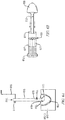
FIGs. 5A-5C are diagrams illustrating a process by which a suppository is manufactured from a substance, e.g., a gel or liquid medication, and in the presence of an assembled drug delivery device; -
FIGs. 6A-6B are diagrams illustrating a process for manufacturing a suppository in the presence of a plunger that is subsequently married to the barrel by inserting the end of the plunger into the forward end of the barrel; -
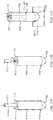
FIGs. 7A-7F and 8A-8E are diagrams of example elements of insertion devices, which may be used in a process for manufacturing a suppository; -
FIG. 7A is a cross-sectional view of an example barrel having inner and outer rings; -
FIG. 7B is a cross-sectional view of an inner ring of a barrel, such as the barrel ofFIG. 7A ; -
FIGs. 7C and 7D are respective cross-sectional and side views of an outer ring of a barrel, such as the barrel ofFIG. 7A ; -
FIG. 7E is a cross-sectional view of the inner ring ofFIG. 7B inserted into the outer ring ofFIG. 7C to form a barrel, such as the barrel ofFIG. 7A ; -
FIG. 7F illustrates an example plunger that includes a side hole; -
FIG. 8A is a cross-sectional view of a plunger that may be used to manufacture a suppository according to an embodiment of the present invention; -
FIGs. 8B and 8C are respective side and cross-sectional views of an example barrel that can be used to manufacture a suppository using a plunger such as the plunger described in reference toFIG. 8A ; -
FIG. 8D is a cross-sectional view of a plunger within a barrel that can be used to manufacture a suppository according to embodiments of the present invention; -
FIG. 8E is a side view of the plunger ofFIG. 8A including a suppository manufactured through the plunger; -
FIGs. 9A through 9D illustrate possible shapes of suppositories manufactured using embodiments of the present invention; -
FIG. 10A is a diagram of a suppository manufactured in the presence of an element configured for insertion of the suppository and including a surface of contact on the outside of the element; -
FIGs. 10B-10C are diagrams of suppositories manufactured in the presence of elements configured for insertions of the suppositories and including contact surfaces on the inside of the elements; -
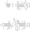
FIGs. 11A-11C are diagrams illustrating example embodiments for manufacturing a suppository from a substance, e.g., a gel or liquid medication, in the presence of a device element and through a gas flow path; -
FIGs. 12A-12E are diagrams illustrating example embodiments for manufacturing a shaped suppository from a substance, e.g., a gel or liquid medication, in the presence of a device element and through a void in the element; -
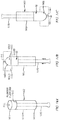
FIGs. 13A-13D are diagrams illustrating an example process of manufacturing a suppository from a front end of a barrel; -
FIGs. 14A-14C are diagrams illustrating other embodiments of a process of manufacturing a suppository from a front end of a barrel; -
FIGs. 15A-15C are diagrams illustrating embodiments of a process of manufacturing a suppository from a front end of a barrel having fins; -
FIGs. 16A-16C are diagrams of example molds that can be used to shape the tip of the suppository during manufacturing including curing; -
FIGs. 17A-17B and 18A-18B are diagrams of example mold liners that can be used to wrap the prefilled suppository and device unit after manufacturing the suppository and allowing it to cure; -
FIGs. 19A-19H are diagrams illustrating an example apparatus and process for manufacturing a suppository using a multiple action convertible mold; -
FIGs. 19I-19K are diagrams illustrating alternative elements and steps in the apparatus and process ofFIGs. 19A-19H ; -
FIGs. 20A-20D illustrate a process for manufacturing a suppository without using a mold; -
FIG. 21A is a diagram of a barrel, plunger, and suppository, each of which defining a respective gas flow path according to an embodiment of the present invention; -
FIG. 21B is a cross section of the suppository ofFIG. 21A ; -
FIG. 22A is a diagram illustrating the barrel, plunger, and suppository in operational arrangement; -
FIG. 22B is a diagram of proximal and distal end axial views of the arrangement ofFIG. 22A ; -
FIGs. 23A-23D are diagrams illustrating an alternative embodiment of a plunger; -
FIG. 24A is a diagram of a suppository insertion device having a plunger and no barrel; -
FIGs. 24B-1 and 24B-2 are diagrams of an alternative embodiment of the suppository insertion device ofFIG. 24A ; - A description of example embodiments of the invention follows.
- The manufacture of suppositories often includes many steps and manual assembly. Typically, the manufacture of suppositories is a molding process whereby a liquid form of a medication or cosmetic is poured into a mold to establish the shape of the solid form. After curing, the solid form is de-molded, packaged into a container or inserted into a device.
- One reason for packaging the applicators and suppositories separately within the same box is due to manufacturing processes currently in place. Typically, the applicators and suppositories are manufactured in separate locations. For example, the suppository applicators are manufactured in an injection molding plastics manufacturing facility, while suppository medications are manufactured in a drug manufacturing facility. After manufacturing, the suppository applicators are packaged in required quantities and shipped to the location of the drug manufacturing. Alternatively, the applicators may be shipped to a packaging location, where the suppositories are shipped as well. Currently, some suppositories are molded in a preformed packaging wrap, which is sealed after curing. Others are molded in a steel parting mold and then demolded and packaged. The final box assembly includes the suppository applicators, the suppositories, and instructions for use.
- Suppositories typically have a shaped end that is specialized, typically rounded, to facilitate insertion into with the body, which is part of the reason why the suppositories are time consuming or labor intensive to manufacture and load into a suppository applicator.
- The multiple steps and arrangement required prior to administration can be difficult for some people with arthritis and other restrictions, necessitating aid from a caregiver or healthcare provider. Furthermore, the patient or caregiver handles the drug prior to administration, leading to a less hygienic administration of the medication. Because suppository medication is designed to melt at body temperature, too much handling can cause the suppository shape to distort, making it difficult to administer.
-
FIG. 1 is a schematic diagram illustrating a method of manufacturing a suppository in accordance with example embodiments of the invention. Asuppository 105 is manufactured 100 in the presence of and in contact with one ormore elements 10 configured to be used to insert the suppository into a cavity of the body. Eachelement 10 can be abarrel 110, aplunger 115, or acombination 102 of a barrel and a plunger. - The suppository can be made from a
substance 50 using a molding process. Thesubstance 50 can be in a liquid, gel, or paste form (generally referred to herein as a liquid 52) orsolid form 54, as schematically illustrated inFIG. 1 . Thesubstance 50 may be poured, injected, instilled, dropped, or otherwise passed through or around a flow path of one or more of theelements 10. The manufacturing can be in the presence of theelement 10, e.g., thebarrel 110 or theplunger 115, in a manner through or around the element or through a gas flow path defined by the element, and can be in contact with an inside or outside of the element. The method may include using theelement 10 to define a shape of thesuppository 105 during the manufacturing. Alternatively or in addition, the method may include using awrapper 145, which can be a mold or a liner to a mold, to define a shape of thesuppository 105. -
FIG. 2 is a flow diagram illustrating a procedure for manufacturing a suppository performed in accordance with example embodiments of the invention. As shown at block 200, a method of manufacturing a suppository includes manufacturing the suppository in the presence of and in contact with anelement 10 configured to be used to insert thesuppository 205 into a cavity of the body. Theelement 10 can be a barrel, a plunger, or a combination of a barrel and a plunger. Thesuppository 105 can be made from asubstance 50 in a liquid, gel, paste or solid form using a molding process. As shown at block 210, manufacturing thesuppository 205 can include causing a form of the suppository to flow (i) through or around theelement 10, or (ii) through a flow path (e.g., gas flow path) defined by theelement 10. In general, the a liquid, gel, paste or solid suppository material may be poured, injected, instilled, dropped, or otherwise passed through or around a flow path of one or more of the elements. As shown atblock 220, thesuppository 205 may be manufactured in contact with an inside or an outside of theelement 10. As shown atblock 230, manufacturing thesuppository 205 can include forming a sealing engagement between theelement 10 and thesuppository 205. As shown at block 240, manufacturing the suppository may include using theelement 10 to define a shape of thesuppository 205 during the manufacturing. - It should be readily appreciated by those of ordinary skill in the art that the aforementioned blocks are merely examples and that the present invention is in no way limited to the number of blocks or the ordering of blocks described above. For example, some of the illustrated blocks may be performed in an order other than that which is described or include more or fewer blocks. Moreover, it should be understood that various modifications and changes may be made to one or more blocks without departing from the broader scope of the present invention. It should also be appreciated that not all of the illustrated flow diagram is required to be performed, that additional flow diagram(s) may be added or substituted with other flow diagram(s).
- Examples of devices and methods for inserting a suppository are described in
U.S. Patent No. 8,192,393 , entitled, "Method And Apparatus For Inserting A Rectal Suppository," issued on June 5, 2012. -
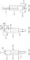
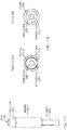
FIG. 3A illustrates an example applicator configured to insert arectal suppository 305 into a human or animal according to the present invention. The applicator may include abarrel 310 and aplunger 315. Thebarrel 310 has agripping end 312 and aninsertion end 307 and is appropriately sized and shaped to fit within a patient's anal canal. Thebarrel 310 is further configured to define agas flow path 320 allowing gas to freely flow through thebarrel 310 when positioned within the anal canal. Theplunger 315 is configured to be substantially longer than the barrel, thereby allowing theplunger 315 to extend beyond the end of thebarrel 310. For example, thebarrel 310 may be approximately 4 cm whereas the plunger may be approximately 8 cm. - Thus, the applicator can be configured to insert a
suppository 305 above a patient's anal trigger zone. In doing so, thesuppository 305 minimizes contact with nerves that trigger the sphincter muscles that may effect (i.e., reduce) the body's ability to retain and absorb medication provided by the suppository. For example, when a suppository is positioned within the anal trigger zone excessive contact with these nerves may create the urge to release contents within the bowel and, along with these contents, a portion of medication that has been released from the suppository but not yet absorbed by the body. It should be noted that the aforementioned dimensions are merely examples and are not meant to be limiting and alternative dimensions may be similarly used such that theplunger 315 extends beyond thebarrel 310. - The
plunger 315 may be configured to be movably or slidably coupled to thebarrel 310 and is further configured to maintain a secondgas flow path 325 that allows gas to freely flow through theplunger 315 as the plunger is withdrawn from the rectum and anal canal after thesuppository 305 has been inserted to a desired position. Thus, as thesuppository 305 is being inserted, thebarrel 310 maintains agas flow path 320 allowing gas to escape. As theplunger 315 is being withdrawn, the plunger'sgas flow path 325 and the barrel'sgas flow path 320 are maintained as the plunger is withdrawn from thesuppository 305 and thebarrel 310 andplunger 315 are removed from the patient's anal canal. The gas flow paths, 325 and 320 allow gas to escape as thebarrel 310 and theplunger 315 are removed from the body preventing or reducing the need to release the gas in the form of flatulence. -
FIGs. 3B and 3C illustrate end views of an applicator that further includes at least one gas flowpath spacing element gas flow path 320. Referring toFIG. 3B , thebarrel 310 includes the at least one gas flowpath spacing element 330 where the spacing element extends inward from an inner wall of thebarrel 310 to contact the outer wall of theplunger 315, thereby maintaining barrel'sgas flow path 320. Since theplunger 315 is hollow, a secondgas flow path 325 is maintained within theplunger 315 as well.FIG. 3C illustrates an alternative example applicator where the at least one gas flowpath spacing element 335 extends outward from an outer wall of theplunger 315 to contact an inner wall of thebarrel 310 to maintain the barrel'sgas flow path 320. Also shown is the at least one secondgas flow path 325 maintained by a similarlyhollow plunger 315. Alternatively, at least two gas flow path spacing elements may simultaneously extend inward from the inner surface of thebarrel 310 and outward from the outer surface of theplunger 315 to maintain the firstgas flow path 320. -
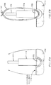
FIGs. 4A-C illustrate employing an applicator to insert asuppository 430 into a patient'srectum 440 in varying states of use. The applicator may include abarrel 410 and aplunger 420. Referring toFIG. 4A , theplunger 420 is positioned within the barrel and thesuppository 430 is loaded into thebarrel 410. The applicator is then inserted into the patient'sanus 435. Referring toFIG. 4B , the plunger is depressed such that thesuppository 430 is inserted within therectum 440 to a desired position, such as a location within a comfort zone above the patient's sphincter muscles 450 (i.e., above an anal trigger zone). As theplunger 420 is inserted or pushed into the barrel, thebarrel 410 maintains afirst gas flow 455 such that any trapped air may escape through thebarrel 410 to outside the patient'sanus 435. Referring now toFIG. 4C , once the suppository has been positioned in the desired location, the applicator may be removed from the patient'srectum 440. As theplunger 420 is removed, suction effects due to withdrawal of theplunger 420 are prevented by venting any pressure or vacuum buildup through the secondgas flow path 465 maintained by theplunger 420. - The examples illustrated in
FIGs. 3A-C and 4A-C are examples of a plunger and barrel configured to maintain a first and second gas flow path. However, numerous other barrel and plunger configurations are envisioned where a first and second gas flow path are maintained within the barrel and plunger, respectively. Furthermore, the suppository defines a gas flow path as described elsewhere herein. - An embodiment of the invention is a process of manufacturing a suppository medication within a drug delivery device that eliminates the arrangement of a suppository and suppository applicator (sometimes referred to herein as components) by the patient or caregiver prior to administration of the suppository. The suppository manufacturing process can be accomplished prior to or after assembly of the drug delivery device and in the presence of one or more elements of the device. After a liquid medication has been poured into association with an element of the suppository applicator, the liquid medication is allowed to cure. After curing, the prefilled device and suppository combination can be packaged as a single unit.
-
FIGs. 5A-5C are diagrams illustrating a process by which asuppository 505 is manufactured from a substance, e.g., a gel or liquid medication, and in the presence of an assembleddrug delivery device 502. As shown inFIG. 5A , adelivery device 502 is pre-assembled and the substance is filled or poured into the assembled device. In this and subsequent figures, arrows and the word "Fill" are used to illustrate the process of filling, pouring, or otherwise causing the substance to flow into an element that is configured for insertion of the suppository. After filling, a curing process completes manufacturing of the prefilled unit. - In some embodiments, the substance, e.g., gel or liquid medication, can be poured within the barrel of the device, and the plunger can be assembled with the barrel-suppository combination after the curing process, a description of which is provided below in reference to
FIG. 11B . Alternatively, the substance can be filled in a mold in contact with the plunger, and, after the curing process is complete, the plunger-suppository combination can be married with the barrel to complete the assembly, a description of which is provided below with reference toFig 6B . - As shown in
FIGs. 5A and 5B , the assembleddevice 502 can include abarrel 510 and aplunger 515 positioned inside thebarrel 510. In the example shown, thebarrel 510 includesfins 530 extending into the inside of the barrel along a length of the barrel. Thebarrel 530 includes avoid space 532, e.g., a space free of fins, to hold the suppository. Thefins 530 providegas flow paths 520 that contribute to proper delivery of the suppository. Thefins 530 are similar to thespacing elements FIGs. 3B and 3C . Alternatively, the fins may extend from the plunger as for example shown inFIG. 3C . Elements (barrels/plungers) need not have fins to define gas flow paths or void spaces, but can have other characteristics or features that define areas of a void or a gas flow path. Examples of plungers having fins or other features, such as cut-out areas, that can establish gas flow paths are described inU.S. Patent No. 8,192,393 ; -
FIG. 5C illustrates theinsertion device 502 sitting in asuppository mold 540 and being filled with liquid medication for manufacturing thesuppository 505. Themold 540 can be used for setting the shape of the suppository end. The mold may include a liner, such as the liners described in reference toFIGs. 17A-18B . - As shown in
FIG. 5C and alsoFIG. 5A , manufacturing can include pouring liquid medication through anend 517 of ahollow plunger 515, one or moregas flow paths 520 in thebarrel 510, ahole 535 in the barrel that provides access to a gas flow path (e.g., a gas flow path between fins 530), or any combination thereof. -
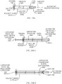
FIGs. 6A-6B are diagrams illustrating the manufacturing of asuppository 605 in the presence of aplunger 615 that is subsequently married to thebarrel 610 by inserting anend 617 of the plunger into the forward end (insertion end 614) of the barrel. - As shown in
FIG. 6A , manufacturing thesuppository 605 can include pouring a substance in liquid form throughopen end 617 ofhollow plunger 615, afill hole 635 in a side of the plunger, or a space outside of the plunger between the plunger and the mold e.g., near theinsertion end 619 of the plunger. Asupport 618 may be used to support theplunger 615 at a specific height abovemold 640. The plunger may be supported until the curing of thesuppository 605 is complete. As shown, there is a surface ofcontact 613, which can be a contact point, between theplunger 615 and thesuppository 605. Manufacturing can include deforming thesuppository 605 around the contact surface or contact point, or allowing curing of the suppository around the contact surface or contact point to facilitate de-molding theplunger 615 andsuppository 605 combination. In some embodiments, there may be more than one contact surface or contact point. - As shown in
FIG. 6B , theplunger 615 andsuppository 605 combination ofFIG. 6A can be married to thebarrel 610 of the insertion device by inserting theback end 617 of the plunger into theforward end 614 of thebarrel 610. Thebarrel 610 may have fins as described above. Thefins 630 can create astop 631 within the barrel, which limits depth of insertion of the plunger and suppository combination into the barrel. Upon insertion of theplunger 615 andsuppository 605 combination into thebarrel 610, one end of thesuppository 605 sits at thestop 631 formed by thefins 630. Also, as described above in reference toFIG. 5A , fins to establish gas flow paths may extend from the plunger. -
FIGs. 7A-7F are diagrams of elements of an example insertion device. The elements or components of the device, i.e., the barrel and the plunger, can help to define the shape of the suppository. For example, abarrel 710 may have a shape that is defined by anouter ring 711 a attached to aninner ring 711 b of a different shape than the outer ring as illustrated inFIG. 7A . Thespace 722 allowed within an inside of theinner ring 711b can be used to hold and cure a liquid medication. In addition, the space between an outside of theinner ring 711b and an inside of theouter ring 711 a can define one or moregas flow paths 720 of the barrel element. The barrel and the plunger of the device may be made of plastic, wood, cardboard or any combination of materials. If the elements are made of plastic, they may be injection molded or extruded as illustrated inFIGs. 7B-7E . - The embodiments shown in
FIGs. 7A-7F are useful for manufacturing a shaped suppository whose beneficial features can include multiple contact surfaces and increased surface area. -
FIG. 7B is a cross-sectional view of an inner ring orinner barrel 711b, which may be made of extruded plastic.FIGs. 7C and 7D are respective cross-sectional and side views of an outer ring orouter barrel 711 a, which may be made of injection-molded or extruded plastic. -
FIG. 7E is a cross-sectional view of theinner ring 711b ofFIG. 7B inserted into theouter ring 711 a ofFIG. 7C to form abarrel 710, such as the barrel ofFIG. 7A . Alternatively, a barrel having the cross-section shown inFIG. 7E can be formed in one piece, for example by extruding the inner and outer rings together. -
Figure 7F illustrates an example extrudedplastic plunger 715 having aside hole 735 added later, i.e., via secondary tooling, to allow filling with a medication or to allow air flow. Any of the elements described herein may have secondary tooling to define the shape of the elements further. Also, the elements may have an addition of a secondary part or parts, which may be made in a different manner or of a different material from the elements themselves. - In some embodiments, the plunger may include multiple pieces similar to the barrel shown in
FIGs. 7A-7F . The plunger may include an inner piece, or inner ring, and an outer piece, or outer ring. The pieces or rings may differ in shape. For example, the plunger may include an extruded inner piece that has a non-circular shape and that is inserted into an extruded or injection-molded outer piece that is round in shape. Alternatively, the plunger may have an outer wall that is star shaped and an inner wall that is round, i.e. circular, in shape. The plunger can be placed or inserted into a round shaped, i.e. circular, barrel. Examples of such plungers and barrels are described in reference toFIGs. 8A-8E . In the examples shown, liquid medication can be filled through one or more spaces or voids between the inner and outer shapes. The star shape of the plunger in contact with the round shape of the inner wall of the barrel would allow gas flow. Further, liquid medication can be filled or poured into, around, or in contact with the plunger, and may be poured within the inner shape of the plunger. In addition, by preventing the liquid to fill the space between the two pieces of the plunger, embodiments can provide for a gas flow path through the plunger. -
FIG. 8A is a cross-sectional view of aplunger 815 that may be used to manufacture a suppository according to an embodiment of the present invention. The plunger includes aninner ring 816b andouter ring 816a, the inner ring being disposed inside the outer ring. The inner ring defines a space or void inside the inner ring, shown asspace 825A inFIG. 8A . Fortunately, the inner ring and outer ring define one or more spaces or voids between the inner ring and the outer ring of the plunger, shown asspace 825B inFIG. 8A . In one example (Option A), the suppository is manufactured throughspace 825A of the plunger. For example, manufacturing includes filling a liquid medication through the void or space defined by the inner ring (space 825A inFIG. 8A ). In this example,space 825B offers a path for gas flow (e.g., air flow) through the plunger. In another example (Option B), the suppository is manufactured throughspaces spaces -
FIGs. 8B and 8C are respective side and cross-sectional views of anexample barrel 810 that can be used to manufacture the suppository using a plunger, such as theplunger 815 described in reference toFIG. 8A . Possible gas flow paths through a device that includes a plunger inside a barrel are described in reference toFIG. 8D . -
FIG. 8D is a cross-sectional view of aplunger 815 within abarrel 810 that can be used in the method of manufacturing a suppository according to embodiments of the present invention. As shown, theplunger 815 includes aninner ring 816b inside anouter ring 816a , as discussed in reference toFIG. 8A . Theplunger 815 defines possiblegas flow paths 825 between the inner and the outer ring. Furthermore, additionalgas flow paths 820 can be provided between theouter ring 816a of the plunger and an inside of thebarrel 810. Manufacturing the suppository using the plunger and barrel combination shown inFIG. 8D may be accomplished, for example, via the two manufacturing options (Option A, Option B) described above in reference toFIG. 8A . -
FIG. 8E is a side view of aplunger 815, such as the plunger described in reference toFIG. 8A , including asuppository 805 manufactured through the plunger. As shown, thetip 806 of the suppository extends beyond the distal end (insertion end) 819 of the plunger. -
FIGs. 9A through 9D illustrate possible shapes of suppositories manufactured using embodiments of the present invention. The figures illustrate possible shapes of suppositories 905a, 905b that can be manufactured using, for example, the barrels or plungers described in reference toFIGs. 8A through 8E . It will be understood that the embodiments ofFIGs. 9A through 9D are merely examples of possible shapes of suppositories, and that suppositories of other shapes can be manufactured through, around, or in connection with plungers, barrels, or combinations of plungers and barrels that are described herein. -
FIGs. 9A and 9C are respective cross-sectional and side views of a suppository 903a manufactured through a space or void in a plunger, such asspace 825B shown inFIG. 8A . -
FIGs. 9B and 9D are respective cross-sectional and side views of asuppository 905b that has been manufactured through a space between an inner ring and outer ring of the plunger, shown asspace 825B of the plunger shown inFIG. 8A . - In some embodiments, the suppository is manufactured to have a sealing engagement between the suppository and one or more elements of the drug delivery device. The sealing engagement can include one or more surfaces of contact, e.g. contact points between the element and the suppository. The contact surfaces or contact points can be on an outside or an inner side of a device element, e.g., on an inside or outside of the barrel or the plunger. The contact surfaces or points can facilitate de-molding of the suppository and can prevent the suppository from falling out of or otherwise separating from the insertion device prior to use by the patient.
- When inserted into a body cavity, suppositories with sealing engagements will naturally release from the element, e.g., the plunger, as the suppository warms up to body temperature and the plunger begins to be withdrawn.
-
FIG. 10A is a diagram of asuppository 1005a manufactured in the presence of an element configured for insertion of the suppository and including a contact point on an outside of the element. As shown, thesuppository 1005a is manufactured to the outside of thebarrel 1010a and includes a contact surface or point 1013a between the outside of thebarrel 1010a and thesuppository 1005a. The insertion device, which includes thebarrel 1010a and aplunger 1015, can be pre-assembled prior to manufacturing of the suppository. - As shown in
FIG. 10A , the contact point 1013a can be a protrusion on the outside wall of thebarrel 1010a. Alternatively, the contact point can be an indentation in the wall of barrel. When the liquid medication or substance solidifies forming the suppository, the medication forms a 'shaped seal' with the protrusion or indentation that prevents thesuppository 1005a from separating from the barrel 1010 until the user administers the suppository. -
FIGs. 10B-10C are diagrams of example suppositories that are manufactured in the presence of elements (1010b, 1010c) configured for insertion of the suppositories and that include contact points on the inside of the elements. As shown inFIG. 10B , the element is abarrel 1010b that includesfins 1030 extending into the inside of the barrel. Thesuppository 1005b is manufactured to the inside of the barrel. A surface of contact, e.g., contact point, between thesuppository 1005b and thebarrel 1010b is located on the inside of the barrel, as shown at 1013b. Alternatively or in addition, there can be one ore more contact points 1013c between the suppository 1005c and thefins 1030 that extend into the inside of the barrel, as illustrated inFIG. 10C . The contact points 1013b, 1013c can prevent the suppository from falling out of the barrel during and after the manufacturing process, for example, when a user is handling the suppository-device combination prior to administration of the suppository. - In any of the embodiments shown in
FIGs. 10A-10C , the liquid medication or substance is placed proximate to the one or more surfaces of contact orcontact points 1013a, 1013b, 1013c in order to ensure the proper sealing engagement of the medication or substance to the element of the device. Manufacturing a suppository according to embodiments ofFIGs. 10A-10C typically includes using a mold, which may be any of the molds described herein, including those described in reference toFIGs. 5C ,6A ,12B-12E, 13C-13D, 14B-14C, 15B-15C ,16A-16C, 17A-17B, 18A-18B and19A-19K . -
FIGs. 11A-11C are diagrams illustrating example embodiments for manufacturing a suppository from a substance, e.g., a liquid medication in the presence of a device element and through a gas flow path. The substance, e.g., liquid medication, can be poured, dropped, or injected into or around one or more of thedevice elements - As shown in
FIG. 11A , the liquid medication can be filled through one or moregas flow paths plunger 1115 assembled within thebarrel 1110. In the example shown, the substance is filled into thebarrel 1110 from a proximal end 1112 (interface end) of the barrel in a direction toward the distal end 1114 (insertion end) of the barrel. - As shown in
FIG. 11B , the liquid medication can be filled through one or moregas flow paths 1120 before assembly of the device, i.e., without theplunger 1115 in place. Theplunger 1115 can then be assembled with thebarrel 1110 after filling. - In the example embodiment illustrated in
FIG. 11C , manufacturing of the suppository includes filling a substance, e.g., liquid medication, throughgas flow paths 1120 of thebarrel element 1110. The gas flow paths are defined by the spaces between the inner guides orfins 1130 on the inside of thebarrel 1110. The guides orfins 1130 may extend from end 1612 along a length of thebarrel 1110 up to afill line 1136. In order to create the shape of the suppository, the barrel is placed inside or in contact with amold base 1140 that has a rounded or bullet shaped tip end for the liquid medication to cure to the final shape. After curing, thesuppository 1105 anddevice element 1110 combination can be de-molded and packaged. -
FIGs. 12A-12E are diagrams illustrating example embodiments for manufacturing a shaped suppository from a substance, e.g., a liquid medication, in the presence of a device element and through a void in the element. As shown, liquid is poured or filled through the void in the barrel and into a mold. A plunger may be inserted through the void after the liquid medication has solidified. -
FIG. 12A shows a cross-section of abarrel 1210 having aninner ring 1211b disposed in anouter ring 1211a for manufacturing a shaped suppository, similar to the embodiment described above in reference toFIG. 7A . A liquid medication can be poured into thebarrel 1210 through the center or void 1222, as shown inFIG. 12A . The manufacturing here is through the void 1222 in thebarrel 1210 that will later accommodate a plunger. Depending on the design of the plunger, there can be a gas flow path through thevoid 1222. - To create a shaped suppository, a suppository mold can include an element or a mechanism that prevents the liquid from reaching and filling the area of the gas flow path.
FIG. 12B is a side view of amold 1240 and a device that includes abarrel 1210. In the example shown, themold 1240 includesmovable mold pins 1242 that extend up into the gas flow paths of thebarrel 1210 to prevent filling in the area of the barrel that is indicated by hatching inFIG. 12B , thereby creating the shape of the suppository. As shown, filling can occur through a void 1222 in thebarrel 1210. In the example shown, thevoid 1222 extends along a central axis of thebarrel 1210. -
FIG. 12C is a side view of abarrel 1210 of an insertion device and amold 1240 that includes one or more elements that prevent liquid medication from filling gas flow paths of the barrel. This figure illustrates the use ofslides 1246 and, in the alternative, the use ofmold pins 1244 as barrier elements that prevent the liquid from filling the gas flow paths. Further description of slides and mold pins is provided below with reference toFIGs. 12D and 12E , respectively. Slides and mold pins can be used to manufacture a shaped suppository, such as the suppository shown inFIGs. 9B and 9D . As shown, aliner 1245 may optionally be used to line themold 1240. Theliner 1245 may be a membrane or skim coat of suitable material applied to the mold. Example liners and membranes are described in reference toFIGs. 16A-16C ,17A-17B and 18A-18B . -
FIG. 12D is a side view of abarrel 1210 of an insertion device and amold 1240 including a slide as a barrier element. In this embodiment, one or more slides orbarriers 1246 extend into an area of thebarrel 1210. The slides prevent the liquid from reaching and filling in the area of the gas flow paths below thefill line 1236. As shown, filling of liquid into themold base 1240 can occur through a void 1222 in the barrel. The slides orbarriers 1246 are removed after the medicine solidifies. -
FIG. 12E is a side view of abarrel 1210 of an insertion device and amold 1240 includingmold pins 1244 as barrier elements. Themold 1240 is a multi-part, action mold that includes amold base 1240 and anupper part 1250. Theupper part 1250 of the mold includes or is coupled topins 1244 that extend into the flow paths of thebarrel 1210. Thepins 1244 are movable with respect to thebarrel 1210 and themold base 1240. Thepins 1244 are supported at a height above themold base 1240 that is determined by the action of theupper part 1250 of the mold, which, in turn, determines how far thepins 1244 extend into thebarrel 1210. The bottom ends 1248 of the mold pins are shaped, e.g., sloped, curved, or rounded, and contribute to shape the suppository. As shown inFIG. 12E , the mold pins 1244 block the filling of liquid medication into the gas flow paths of thebarrel 1210. Filling is accomplished through the void 1222 in thebarrel 1210, which, as shown, is located in the center of the barrel. The actions or movements of the mold pins 1244 can include at least two steps. First, before the filling of the barrel and mold with the liquid suppository material, the mold pins 1244 move into the gas flow paths to seal the gas flow paths, thereby preventing the liquid from entering the area of the gas flow paths. Second, after the filling and solidification of the suppository material, the mold pins 1244 retract, leaving the molded, solidified suppository in place in thebarrel 1210, and in a desired relation to the barrel, to allow gas flow through gas flow paths. Optionally, cooling may be included during the mold actions to reduce cycle time, thereby increasing speed of manufacturing. A description of cooling a mold during the manufacturing process is proved below in reference toFIGs. 19I-19K . - As shown in
FIG. 12E , the mold pins 1244 that extend into thebarrel 1210 are sloped at the bottom 1248, allowing for a shape of the suppository that is rounded at the back end of the suppository. The shape offers more surface area, which may offer a beneficial therapeutic effect. The rounded shape at the back end of the suppository may also offer a comfort shape that can contribute to increased acceptance by the patient, as compared to standard suppositories, which are typically bullet shaped and include a flat back end. -
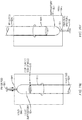
FIGs. 13A-13D are diagrams illustrating an example process of manufacturing a suppository from a front end (insertion end) of a barrel. In a first step, as shown inFIG. 13A , a substance, such as a liquid medicine, is poured into thebarrel 1310 from the front end (insertion end) 1314 of the barrel.Moveable pins 1344 placed in each gas flow path of thebarrel 1310 prevent the liquid medicine from filling in the gas flow paths. Thepins 1344, which are supported by asupport 1350, provide a tight seal during manufacturing of the suppository. As shown inFIG. 13A , thepins 1344 are flush to the same point. -
FIG. 13B is a cross-sectional view of the device ofFIG. 13A and illustrates the outline of the element, i.e., thebarrel 1310, and the mold pins 1344, which are shown as shaded areas. The mold pins 1344 are flush at the same level within thebarrel 1310, as shown inFIG. 13A . - In a second step, as shown in
FIG. 13C , themold base 1340 for the suppository tip is positioned against, and optionally coupled to or attached to, the top forward end (insertion end) of thebarrel 1310, after theliquid medication 52 has been poured or otherwise filled into thebarrel 1310. Themold base 1340 can have a rounded or bullet shapedportion 1343 to form the tip end of the suppository. Themold 1340 has anaperture 1341. In the orientation of themold 1340 as shown inFIG. 13C , theaperture 1341 is located at the top and allows air or gas to escape from the void 1322 between the level of theliquid medication 52 and the inner side of the top of themold 1340. Initially, there is a void 1322 above the liquid medicine in the barrel. A mold action can move the mold pins 1344 up, as indicated by the arrows inFIG. 13C , letting the gas escape from thetop void 1322 as the liquid 52 is caused to move up into themold 1340 by the movement of the mold pins. - In a third step, a
pin 1355 is inserted into theaperture 1341 in themold 1340 to close the aperture. In a fourth step, with theaperture 1341 closed bypin 1355, themold 1340,suppository 1305, and device (barrel 1310) are flipped, as shown inFIG. 13D , and the mold pins 1344 are retracted, as indicated by the arrows inFIG. 13D . In a fifth step, thesuppository 1305 is allowed to cure. - The actions of the mold in the example process illustrated in and described with reference to
FIGs. 13A-13D can be fast. For example, retraction of the mold pins 1344 in the fourth step will allow the suppository material, e.g., liquid 52, to settle before curing. - Alternatively, the suppository medication can be manufactured into the drug delivery device without using a gas flow path of the delivery device for filling.
FIGs. 14A-14C are diagrams illustrating embodiments of a process of manufacturing a suppository from a front end of a barrel. - As shown in
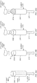
FIG. 14A , adevice 1402, including abarrel 1410 preassembled with aplunger 1415, is held upright during the first half of the manufacturing process. Theplunger 1415 can be solid or formed with aplatform base 1460, as shown. Theplunger 1415 is kept at a level low enough to allow for the proper dose of liquid medication to be filled into the forward end (insertion end) 1414 of thebarrel 1410. As shown an end of the plunger extends out the proximal end (interface end) 1412 of the barrel. After the liquid medication has been poured or otherwise filled into thebarrel 1410, amold 1440 having a rounded or bullet shapedtip end 1443 is positioned over, and is optionally coupled to or attached to, the top forward end (insertion end) 1414 of the barrel as illustrated inFIG. 14B . Alternatively, or in addition, the filled unit (barrel 1410) can be placed up into themold 1440 via a manual or automated process. The mold 1440 (also referred herein as a mold base) has anaperture 1441 that allows the escape of air or other gas from the void 1422 between the level of theliquid medication 52 and the inner side of the top of themold 1440. A mold action at the end of theplunger 1415 advances the solid plunger, or plunger withplatform 1460, up (indicated by arrows inFIG. 14B ), to push the liquid 52 into themold 1440 and any gas (e.g., air) within thevoid 1422 out of theaperture 1441 in the top of the mold. Alternatively, theplunger 1415 may be advanced manually. As illustrated inFIG. 14C , apin 1455 is inserted into theaperture 1441 in themold base 1440 to seal the aperture, and the entire apparatus is flipped upside down. The suppository material, e.g.,liquid medication 52, is then allowed to cure. Thereafter, thesuppository 1405 anddevice 1402 combination can be de-molded and packaged. - For devices that include a hollow plunger that is open at both ends, one can use a solid rod in the mold. The mold actions, i.e., movements of the solid rod, for moving the gas out through the aperture in the mold can be the same as those described for the
plunger 1415 shown inFIG. 14B . After the suppository has been allowed to cure, the solid mold rod can be removed and the hollow plunger inserted into the barrel containing the suppository. Example mold actions of a solid rod that moves into and out of a mold during the manufacturing of a suppository are illustratedFIGs. 19A-19K , and are described elsewhere herein. -
FIGs. 15A-15C are diagrams illustrating an embodiment of a process of manufacturing a suppository from a front end of abarrel 1510 havingfins 1565. - As shown in
FIG. 15A , adevice 1502, including abarrel 1510 preassembled with aplunger 1515, is held upright during an initial phase of the manufacturing process. Theplunger 1515 can be solid or formed with a platform base 1560 (FIG. 15B ), as shown. Theplunger 1515 is kept at a level low enough to allow for the proper dose of a substance, e.g., liquid medication to be filled into the forward end (insertion end) 1514 of thebarrel 1510. After the liquid medication has been poured or otherwise filled into thebarrel 1510, amold 1540 having a rounded or bullet shaped tip end 1543 is positioned over, and is optionally coupled to or attached to, the top forward end (insertion end) 1514 of the barrel as illustrated inFIG. 15B . Alternatively, or in addition, the filled unit (barrel 1510) can be placed up into themold 1540 via a manual or automated process. Themold 1540 has anaperture 1541 that allows the escape of air or other gas from the void 1522 between the level of theliquid medication 52 and the inner side of the top of themold 1540. A mold action (or alternatively, applied manual force) at the end of theplunger 1515 advances the solid plunger, or plunger with platform 1560, up (indicated by arrows inFIG. 15B ), to push the liquid 52 into themold 1540 and any gas (e.g., air) within thevoid 1522 out of theaperture 1541 in the top of the mold. As illustrated inFIG. 15C , a pin 1555 is inserted into theaperture 1541 in themold base 1540 to seal the aperture, and the entire apparatus is flipped upside down. The suppository material, e.g.,liquid medication 52, is then allowed to cure. Thereafter, thesuppository 1505 anddevice 1502 combination can be de-molded and packaged. - The
suppository 1505 is manufactured in contact with or around thefins 1565 of thebarrel 1510, which helps to secure the suppository in the barrel during packaging, shipping and subsequent administration by a user. - Described herein are molds that shape the tip of the suppository. Such molds may be made from, for example, steel, wood, plastic, silicone, or any combination of materials. The molds may be firm or pliable, thick or thin, allowing for the shaping of the end of the suppository. Rather than through a mold, a secondary process, such as thermal melting, could be used to shape the tip of the suppository.
-
FIGs. 16A-16C are diagrams of example molds that can be used to shape the tip of the suppository during manufacturing including curing. In the embodiment shown inFIGs. 16A-16B , mold 1640a includes a mold tip that is made of a thin silicone membrane 1640b which, after curing, allows for ease of de-molding by pushing on the silicone membrane 1640b to release the suppository and device combination. Alternatively, the mold may become a part of the packaging after curing. - As shown in
FIG. 16C , multiple units can be filled with the use of amold rack 1670. Themold rack 1670 supports themold 1640c for molding multiple units ofsuppositories 1605. As shown, themold 1640c is placed on top of themold rack 1670, with the mold rack including cut-outs orcavities 1671 for receiving the portions of themold 1640c that shape the tip of the suppository. After curing, the units can be separated atseparation line 1675. The filled unit, along with the mold acting as a protective cap, can then be packaged. -
FIGs. 17A-18B are diagrams of example mold liners that can be used to wrap a prefilled suppository and device unit after manufacturing and curing. Amold 1740 may have aliner 1745 that allows the entire manufactured unit (i.e.,suppository 1705,barrel 1710 any plunger 1715) to be wrapped in the liner of the mold after the curing of the suppository medication as shown inFIGs. 17A-17B . As shown inFIG. 17B , themold liner 1745 is wrapper that is sealed at the top 1747 andsides 1749, thus forming a packaging for the unit. The wrapping 1745 can be a liner to a mold, as shown, or it can be the mold itself. In one embodiment, themold liner 1745 may be a sleeve that the entire unit fits into. The mold liner holds the shape of the tip of the suppository and folds up to seal the entire unit. The individual unit can be opened with the use of a pull tab, by separation of a two-part package with multiple tabs, by unwinding of a bound package, or by other suitable means for opening a sealed packed as is known in the art.FIGs. 18A and 18B illustrate awrapper 1845 that is a fitted sock fitting snug at the end of thebarrel 1810. Thewrapper 1845 can be a mold or a mold liner. As shown inFIG. 18A , the device (i.e.,suppository 1805,barrel 1810, and plunger 1815), including thewrapper 1845, can be held upright by a holder anywhere along the device until curing is complete. Two example holders and example positions for holding the device are illustrated asholder 1872 andholder 1874 inFIG. 18A . After curing, thewrapper 1845 is unrolled upward, as illustrated inFIG.18B , and sealed at the top. -
FIGs. 19A-19H are diagrams illustrating an apparatus and process for manufacturing a suppository using a multiple action, convertible mold. The figures show the steps of manufacturing the suppository and the elements and actions of a multiple action, convertible mold.FIGs. 19I-19K are diagrams illustrating alternative elements and steps of the apparatus and process ofFIGs. 19F-19H . Thus, two options for curing and de-molding are illustrated, with the elements and steps illustrated inFIGs. 19A-19E being the same in the manufacturing process for both options. - As shown in
FIG. 19A , amold 1940 includes twoparts mold 1940 can part open atparting line 1972 for insertion of a device element, e.g.,barrel 1910. Parting ofmold 1940 is one mold action of the multi-part mold.FIG. 19A shows thebarrel 1910 positioned inside themold 1940. Also shown is a void 1922 between thebarrel 1910 and themold 1940. Thevoid 1922 is in fluid communication with anaperture 1941 in themold 1940, which allows for filling of the void with suppository material through the aperture. An opening or channel 1970 is provided inmold 1940 to receive amold rod 1974 of the multi-part mold, as shown inFIG. 19B . Themold rod 1974 can be a solid rod member. In one mold action, the solid rod rises up through opening 1970 and into thebarrel 1910 until the rod reachesstop point 1976. Themold rod 1974 can be configured to completely fill the cross-sectional area of thebarrel 1910. In this way, themold rod 1910 can prevent the suppository material, e.g., liquid medicine, from leaking out past the rod during filling of themold 1940 with suppository material and subsequent manufacturing processes. - As shown in
FIG. 19C , once themold rod 1974 is in place,suppository material 52, e.g., liquid medicine, is filled throughaperture 1941 and void 1922 into thebarrel 1910. - As illustrated in
FIG. 19D , another mold action moves themold rod 1974 up toward theaperture 1941, thereby moving thesubstance 52 into thevoid 1972 and displacing any gas present. As therod 1974 moves up, the gas can escape throughaperture 1941. -
FIG. 19E shows themold rod 1974 after having moved up toward theaperture 1941 andpast stop point 1976 ofFIG. 19D to stoppoint 1977. In another mold action, apin 1955 is inserted into theaperture 1941. Alternatively, another rod member is moved down into theaperture 1941. - In one option (Option A), illustrated in
FIGs. 19F-19H , the process for manufacturing the suppository includes flipping themold 1940 before allowing thesuppository material 52 to cure. By flipping the mold in Option A, as shown inFIG. 19F , thesuppository material 52 can settle withgravity forming suppository 1905 and, therefore, the cycle time can be reduced. As shown inFIG. 19G , the pin 1955 (or rod) is removed fromaperture 1941 and themold rod 1974 is retracted from themold 1940, which can be accomplished by one or more mold actions.FIG. 19H illustrates parting of themold 1940 alongparting line 1972 intoparts suppository 1905 and device (i.e., barrel 1910) can be ejected from themold 1940 via the parting mold action. - In another option (Option B), illustrated in
FIGs. 19I-19K , the process includes injection of a cooling fluid to solidify the suppository liquid medication without flipping themold 1940. That option may be particularly suited for use in an automated process. Cooling can also be used in Option A to further reduce cycle time. As shown inFIG. 19I , cooling fluid (e.g., cold water) is circulated throughchannels 1980 inmold 1940. The cooling can speed the curing process of the suppository material. After the circulation of cooling fluid is stopped, the pin 1955 (or rod) is removed from theaperture 1941 and themold rod 1940 is retraced from thebarrel 1910 and out of themold 1940, as shown inFIG. 19J . Next, as shown inFIG. 19K , themold 1940 separates alongparting line 1972 and ejects thesuppository 1905 and device (barrel 1910) combination. - Mold actions or movements of a
mold rod 1974 of a multiple action mold are shown inFIGs. 19A-19K and have been described in reference tomold 1940. The same or similar mold may be convertible to allow similar mold actions with a plunger that has a platform, such as theplunger 1415 shown inFIG. 14A-14C . In the case of a plunger with a platform, the mold actions can convert to using the plunger instead of the solid rod that is shown inFIGs. 19A-19K . The advantage of a convertible, multi-action mold is that any suppository can be manufactured within the barrel with any plunger, including those described herein. A manufacturing system that includes a convertible mold may be configured to allow forming suppositories of multiple sizes and to accommodate plungers of varied designs. If, for a particular product, a plunger with a platform is desired, the system can fill the suppository material, e.g., liquid drug, into the insertion device just as for a solid or hollow plunger. The ability to accommodate plungers of different designs can reduce the cost of manufacturing the suppositories. - Although embodiments are shown with a convertible mold positioned vertically, the mold may be positioned sideways. A sideways mold may also include an aperture in the mold to allow air or gas to escape the void in the mold during or after the filling of the mold with the suppository material. It may be useful to position the mold sideways to be able to utilize gravity in the parting of the mold, the insertion of a blank barrel, and the ejection of the finished product.
-
FIGs. 20A-20D illustrate example processes for manufacturing a suppository without using a mold or a wrapper. As shown inFIG. 20A , anelement 2002 includes abarrel 2010 and aplunger 2015 positioned in the barrel. As shown, theplunger 2015 includes aplatform 2046. A mechanical seal is established between theplatform 2046 and the inside of thebarrel 2010. Alternatively, a seal can be established via pins or slides, as for example described in references toFIGS. 12C-12D . - As shown in
FIG. 20B , a solid orsemi-solid suppository substance 50 is applied intoelement 2002 using anapplication nozzle 2080. Thenozzle 2080 is initially positioned at or withinelement 2002 and injects thesubstance 50 while withdrawing from theelement 2002. Withdrawing the nozzle at a constant rate and using an appropriately shaped nozzle, one can create asuppository 2005a with a straight domed shape, as shown inFIG. 20B . Withdrawing thenozzle 2080 with intermittent pausing can created asuppository 2005b with a scalloped shape, as shown inFIG. 20C . Twisting thenozzle 2080 during withdrawal can created a suppository with a twisted shape, as shown inFIG. 20D . A wrapper (not shown) may be applied to the element and suppository after shaping of the suppository. - The efficacy of many drugs administered orally may be reduced or inactivated in the stomach because of acidic and/or enzymatic content of the stomach or because the drug may be subject to digestive attack and/or to microbial degradation. Oral administration of drugs also directs the absorbed substances through the metabolism process, including the liver and the kidneys, where the drugs' effectiveness can be further reduced or inactivated. Drug dosages are carefully scrutinized for absorption rates in order to prevent overburdening the liver and kidney organs. Non-steroidal anti- inflammatory drugs can cause severe digestive distress when administered orally. For these reasons, rectal medication is often a more effective mode of delivery for the administration of a variety of drugs for various medical conditions.
- Rectal suppositories are composed of active pharmacological ingredients and inactive binding agents that maintain the drug in a desired shape and stable form prior to, and during, insertion into the rectum. The inactive binding agents are designed so that the suppositories remain stable at or below room temperature. Depending on the binding agent used, the suppository is designed to melt or dissolve at, or above, body temperature or by absorbing water, so that the active pharmacological ingredient can be released for absorption by the mucosa lining of the rectum. Rectal suppositories are formed to ease insertion and are commonly manufactured to maintain a torpedo or bullet shape appearance.
- Rectal suppositories employ medications that offer topical and/or systemic therapeutic effects. The active ingredient in rectal suppositories is often intended to be directly absorbed in by the rectal venous plexus to be distributed throughout the body by the blood circulation bypassing the portal vein and the liver. Therefore, a rectally applicable medicament form is preferable, particularly for the drugs for which the effective ingredient causes stomach disorder with oral administration or the ingredient is susceptible to decomposition in the digestive tract or liver, resulting in a decreased effectiveness of the medication.
- The effectiveness and benefit of rectal suppositories can be improved with proper positioning within the rectum, above the anorectal line (i.e., above the dentate line dividing the anal canal and the rectum). For example, rectal suppositories used for the treatment of internal hemorrhoids may be best able to treat the origin of the inflammation if the suppository is placed in the lower rectum, just above the anorectal line. On the other hand, rectal suppositories used to treat digestive diseases, such as ulcerative proctitis or distal colitis, may be better positioned higher in the rectum at a location of the farthest site of disease origin.
- Figures 1A and1B of
U.S. Application No. 12/287,215, filed on October 7, 2008 - Currently, medication is delivered rectally in a liquid form as a suspension enema, a solid form as a suppository, or a cream, ointment or foam. All of these modes of administration have the disadvantage of leaking from within the body to outside the body quickly after insertion using today's insertion techniques. These modes of administration also cause pain and discomfort in varying degrees. Liquid medications and foam are intended to be retained for at least 3 hours. Because of the bodily impulse to eliminate the contents of the bowel, patients struggle to retain the medicine and are often given sedatives to help relax the body. Rectal suppositories have similar disadvantages, including the time required for the medication to melt before being absorbed by the mucosa lining of the rectum. Finally, creams and ointments, although effective for the topical therapeutic of external tissues and areas affected by prolapsed of internal hemmorrhoids, do not reach the treatment area above the anorectal line or the rectum, where hemorrhoids originate and gastrointestinal diseases present themselves.
- Proper positioning of rectal medication is important and can have an impact on the efficacy of the treatment. For example, internal hemorrhoids develop in the lower rectum above the anorectal line. Treatment with suspension enemas places the medication above the anorectal line. Treatment with creams and ointments do not reach the anorectal line and only treat the hemorrhoids if they are prolapsed. Suppository medication is the preferred treatment for hemorrhoids, but using the current delivery method, i.e., by using a finger, the medication does not have proper contact with the affected area and, as the suppository melts, it leaks from inside of the body to outside the body. Application of medication within the lower rectum aids in the treatment of hemorrhoids while the medication is in contact with the affected area. Further benefit comes from a drug delivery system that helps the medication stay in the proper position without leaking from inside to outside of the body.
-
Figure 21A illustrates an example embodiment of an applicator including ahollow barrel 2110 and aplunger 2115. Thebarrel 2110 has open proximal 2112 and distal 2114 ends defining agas flow path 2120, which may be one or more, allowing gas to flow freely through the barrel when thedistal end 2114 is positioned in the anal canal and rectum. Theproximal end 2112 is defined herein as the end which theplunger 2115 enters, and the distal 2114 end is defined herein as the end past which the plunger pushes thesuppository 2105 as it travels toward the rectum. - The
barrel 2110 is appropriately sized and shaped to fit within the patient's anal canal and rectum. Theplunger 2115 may also be hollow and have open proximal and distal ends defining agas flow path 2120, allowing gas to flow through the plunger and the barrel. The barrel and plunger are movably coupled together. In some embodiments, the plunger is slightly longer than the barrel. For example, the barrel may be approximately 7 ½ cm, whereas the plunger may be 8 cm. Other lengths are suitable for administration purposes. Also illustrated is ahollow suppository 2105 withopen ends gas flow path 2190, thereby allowing gas to flow through thesuppository 2105, theplunger 2115, and thebarrel 2110 while the suppository is loaded in the applicator and the plunger is movably coupled with the barrel. -
Figure 21B illustrates a cross section of thesuppository 2105 with its gas flow path (open space 2192) through the medicament combination 2194 of base and active ingredient. It should be understood that a single gas flow path may be defined by the suppository, including open-structure gas flow paths at the radial edge of the suppository. -
Figure 22A illustrates an applicator configured to insert asuppository 2205 into a human or animal according to an embodiment of the present invention. The applicator may include abarrel 2210 and aplunger 2215 configured to allow gas to flow freely through a gas flow path of the applicator during the administration placement of thesuppository 2205 past the anus into the rectum and during withdrawal of the device from the rectum and anus. - The gas flow path may be a single gas flow path or multiple gas flow paths. The suppository may be loaded in the proximal end or distal end of the applicator, depending on an internal structure of the
barrel 2210,plunger 2215, or combination thereof. Thesuppository 2205 further allows gas to flow freely through the gas flow path, illustrated asopen space 2292, during administration, where the gas flow path of the suppository and plunger are arrangeable to be aligned. -
Figure 22B illustrates the cross section of the assembled applicator (i.e.,barrel 2210 and plunger 2115) with thesuppository 2205 from distal and proximal ends perspectives. The gas flow path, illustrated byopen space 2292, is maintained through the apparatus and thesuppository 2205 from both ends, thereby allowing gas to flow freely during the administration placement of thesuppository 2205 past the anus into the rectum and during withdrawal of the device from the rectum and anus. -
Figures 23A-23D illustrate another example embodiment of an applicator including a plunger that continues to maintain the gas flow path(s). Numerous other plunger configurations are envisioned where the gas flow path is maintained within the applicator and suppository during use. -
Figure 23A illustrates an example embodiment of an applicator including ahollow barrel 2310 and aplunger 2315. Thebarrel 2310 has open proximal 2312 and distal 2314 ends defining agas flow path 2320, which may be one or more, allowing gas to flow freely through the barrel when thedistal end 2314 is positioned in the anal canal and rectum. Thebarrel 2310 is similar tobarrel 2110 described in reference toFIG. 21A . Theplunger 2315 hasfins 2320 configured to maintain gas flow path(s) 2120 when the plunger is inserted into thebarrel 2310, allowing gas to flow between theplunger 2315 and thebarrel 2310. Thebarrel 2310 andplunger 2315 are movably coupled together. Theplunger 2315 can be slightly longer than thebarrel 2310. For example, the barrel may be approximately 7 ½ cm, whereas the plunger may be 8 cm. Other lengths are suitable for administration purposes. - Also illustrated in
FIG. 23A is ahollow suppository 2305 withopen ends gas flow path 2390, thereby allowing gas to flow through thesuppository 2305 and through one or more flow paths, e.g., gas flow paths defined by theplunger 2315 and thebarrel 2310, while the suppository is loaded in the applicator and the plunger is movably coupled with the barrel. -
FIG. 23B illustrates a cross section of theplunger 2315 havingfins 2330.FIG. 23C illustrates a cross section of theplunger 2315 positioned within thebarrel 2310, including open spaces 2320 (gas flow paths) defined between thefins 2330 of theplunger 2315 and an inside of thebarrel 2310.FIG. 23D illustrates a cross section of theplunger 2315 withinbarrel 2310 withsuppository 2305 loaded into the device. Open spaces 2320 (gas flow paths) defined between thefins 2330 of theplunger 2315 and an inside of thebarrel 2310 are in fluid communication with agas flow 2390 path defined through thesuppository 2305. - In an alternative embodiment, as illustrated in
FIG. 24A , a single element, referred to herein as a plunger 2415a, defines a gas flow path 2425a. The gas flow path 2425a is configured to allow gas to flow from the rectum to outside the body while a distal end of the plunger 2415a is within the rectum and, using the same configuration, maintains the gas flow path 2425a until the plunger is withdrawn fully outside the body. In an embodiment in which the plunger is used in conjunction with a suppository that defines a gas flow path, the gas flow path of the plunger is aligned with the gas flow path of the suppository during application of the suppository into the rectum. - It should be understood that the shape of the suppository illustrated in
FIG. 24A with a gas flow path associated therewith can be produced using molding techniques described herein or the gas flow path(s) can be formed (e.g., bored or, for example, melted with a thin rod (not shown) after a suppository has been solidified without a gas flow path. - A mechanism (not shown), such as a piston rod as illustrated in
FIGs. 24B-1 and 24B-2 and described below, may be employed to push the suppository 2405a from the plunger 2415a into position once the distal end of the plunger is within the rectum. The piston rod may be configured to maintain the gas flow path of the plunger throughout or for portions of the insertion and withdrawal processes such that the suppository is appropriately positioned within the rectum by the patient or person performing the application task. - In one example embodiment, the plunger 2415b includes a
piston rod 2496 that can push the suppository 2405b from within asuppository compartment 2498, at a distal end of the plunger, past an end of the compartment and into the rectum.FIG. 24B-1 illustrates the position ofpiston rod 2496, includingpiston rod handle 2497, relative to plunger 2415b before the suppository push.FIG. 24B-2 illustrates the position ofpiston rod 2496, includingpiston rod handle 2497, after the suppository push. The gas flow path(s) 2425b are maintained from insertion of the suppository into the rectum until withdrawal of the plunger from the anus to ensure suction does not displace the suppository from its resting position in the rectum following insertion. - It should be understood that holes or gaps may be provided in a wall of the
compartment 2498 to allow air and gas to enter the compartment and gaseously connected gas flow path, thereby minimizing or eliminating air or gas from being pushed into the rectum to prevent discomfort from inserted gas or expulsion of the suppository shortly after insertion because of inserted gas. The holes or gaps are configured (e.g., sized and shaped) such that little to no effects on sensitive tissue during the insertion and withdrawal processes are experienced by the patient. For example, many small holes can be employed to provide a substantially smooth surface rather than large apertures. - Alternatively, the
piston rod 2496 or other element(s) (not shown) may be configured to provide suction of gas, but not the suppository, while the distal end of the plunger is within the rectum to withdraw inserted gas so as to reduce discomfort caused from inserted gas or expulsion and reduce likelihood the suppository will be expelled shortly after insertion because of the inserted gas. - Certain diseases are treated by way of a suppository containing a drug. Current suppositories have "torpedo" configurations, and, therefore, can be difficult to insert into a rectum or, even if inserted, may be dislodged due to insertion of air into the rectum during the insertion process. An embodiment of the present invention configures the suppository to have at least one gas flow path. Another embodiment includes a suppository with gas flow path and suppository insertion device with gas flow path configured to align with the suppository gas flow path. Through use of the suppository insertion device, the suppository can be properly inserted into the rectum with comfortable and effective results for a patient.
- While this invention has been particularly shown and described with references to example embodiments thereof, it will be understood by those skilled in the art that various changes in form and details may be made therein without departing from the scope of the invention encompassed by the appended claims.
Claims (31)
- A method of manufacturing a suppository and element combination, the method comprising:manufacturing a suppository (105, 205, 305, 430, 505, 605, 805, 905a, 905b, 1005a, 1005b, 1005c, 1105, 1305, 1405, 1505, 1605, 1705, 1805, 1905, 2005a, 2005b, 2005c, 2105, 2205, 2305, 2405a, 2405b) in the presence of and in contact with an element (10, 102, 110, 115) configured to be used to insert the suppository into a cavity of a body, the element defining a gas flow path, and wherein manufacturing the suppository includes manufacturing the suppository in a manner defining a gas flow path (2190, 2192, 2292, 2390) therethrough, the gas flow path of the suppository configured to communicate with the gas flow path of the element.
- The method of claim 1, wherein the element is a barrel, plunger, or combination thereof.
- The method of claim 2, wherein the element is the combination of the barrel and plunger, and wherein manufacturing the suppository includes forming a shape of the suppository while the plunger is within the barrel.
- The method of claim 3, further comprising positioning the combination of the barrel and plunger in contact with a wrapper prior to forming the shape of the suppository.
- The method of claim 4, wherein the wrapper is a liner to a mold and wherein manufacturing the suppository includes shaping an end of the suppository through use of the wrapper and the mold.
- The method of claim 4, wherein the wrapper is a mold and wherein manufacturing the suppository includes shaping an end of the suppository through use of the wrapper.
- The method of any of the preceding claims, wherein manufacturing the suppository includes causing a form of the suppository to flow through or around the element, or through a flow path defined by the element.
- The method of any of the preceding claims, wherein manufacturing the suppository includes manufacturing the suppository in contact with an inside or outside of the element.
- The method of claim 1, wherein manufacturing the suppository includes manufacturing the suppository from a substance in a liquid, gel, paste, or solid form using a molding process.
- The method of claim 9, wherein manufacturing the suppository includes causing the substance to pass through a mold into contact with the element, or pouring the substance through or around a flow path of the element, or manufacturing the suppository from solid pieces that are liquefied and then re-solidified to form the suppository.
- The method of any of the preceding claims, wherein manufacturing the suppository includes forming a sealing engagement between the element and the suppository.
- The method of claim 11, wherein the sealing engagement includes a surface of contact between the element and the suppository, the surface of contact being configured to hold the suppository in engagement with the element until a user administers the suppository and, optionally, wherein the sealing engagement includes multiple surfaces of contact between the element and the suppository.
- The method of claim 11, wherein the sealing engagement is formed at a protrusion of the element, or at an indentation of the element or at a hole of the element.
- The method of claim 1, wherein the element includes a front end, configured for insertion into the body cavity, and a back end, configured for interfacing with a user's hand, and wherein manufacturing the suppository includes causing a liquid form of the suppository to flow in a direction toward the front or back end of the element.
- The method of claim 1, wherein manufacturing the suppository includes forming a solid suppository and subsequently forming a hole therethrough, the hole defining the gas flow path.
- The method of claim 1, further comprising molding the gas flow path during the manufacturing.
- The method of any of claims 1, 15, or 16, wherein manufacturing the suppository with the gas flow path is performed in a manner resulting in an axial alignment between the gas flow paths of the element and the suppository or includes arranging the suppository and the element to align the gas flow paths of the element and suppository axially.
- The method of any of claims 1, 15, or 16, wherein manufacturing the suppository with the gas flow path is performed in a manner resulting in a non-axially alignment between the gas flow paths of the element and the suppository while still maintaining gas flow through or around the suppository and the element or includes arranging the suppository and the element to maintain the gas flow paths of the element and suppository non-axially.
- The method of any of the preceding claims, further comprising using the element to define a shape of the suppository during the manufacturing.
- The method of claim 1, further comprising:employing a wrapper to assist in forming a shape of the suppository; andsealing the wrapper with the element and suppository contained therein.
- The method of claim 20, wherein the wrapper is a liner to a mold configured to shape an end of the suppository or the wrapper is a mold configured to shape an end of the suppository.
- A kit comprising:a suppository (105, 1705, 1805) that defines a gas flow path (2190, 2192,2292,2390);an element (10, 102, 110, 115, 1710, 1715, 1810, 1815) configured to be employed to insert the suppository into a body cavity, the element defining a gas flow path that is configured to communicate with the gas flow path of the suppository; anda wrapper (145, 1745, 1845) sealed with the element and suppository contained therein,the suppository having a shape that is defined by aspects of the element and the wrapper.
- The kit of claim 22, wherein the suppository includes a sealing engagement between itself and an interior or exterior of the element.
- The kit of claims 22 or 23, wherein the gas flow paths of the element and the suppository are axially or non-axially aligned.
- The kit of any of claims 22 to 24, wherein the element is a barrel, plunger, or combination thereof.
- A suppository (105, 205, 305, 430, 505, 605, 805, 905a, 905b, 1005a, 1005b, 1005c, 1105, 1305, 1405, 1505, 1605, 1705, 1805, 1905, 2005a, 2005b, 2005c, 2105, 2205, 2305, 2405a, 2405b) comprising:an active ingredient; andan inactive agent used to define a solid geometrical shape containing the active ingredient, the solid geometrical shape defining at least one gas flow path (2190, 2192, 2292, 2390), the gas flow path arranged to communicate with a gas flow path of an element configured to be employed to insert the suppository into a body cavity.
- The suppository of claim 26, wherein the inactive agent is an inert agent.
- An apparatus for inserting a rectal suppository into an animal or human, comprising:a barrel (110, 2110, 2205, 2310) configured to be inserted into an anal canal or rectum and having proximal and distal ends;a plunger (115, 2115, 2215, 2315) configured to be movably coupled to the barrel and defining a gas flow path; anda suppository (105, 2105, 2205, 2305) defining a gas flow path therethrough and configured to have its gas flow path in fluid communication with the gas flow path of the plunger and maintain the gas flow path into and out of the body during a state of insertion of the suppository into the anal canal or rectum and during withdrawal of the plunger away from the suppository and out of the body.
- The apparatus of claim 28, wherein the gas flow path of the suppository is aligned with the gas flow path of the plunger.
- An apparatus comprising:a plunger (115, 2115, 2215, 2315, 2415a, 2415b) and suppository (105, 2105, 2205, 2305, 2405a, 2405b) combination, the plunger defining a gas flow path and the suppository defining a gas flow path that communicates with the gas flow path of the plunger, the combination of the plunger and suppository configured to insert the suppository past an anus and into a rectum while maintaining the gas flow paths during insertion of the suppository and withdrawal of the plunger out of the rectum and anus.
- The apparatus of Claim 30, wherein the suppository is solid and wherein the plunger includes a piston rod configured to push the suppository away from the plunger.
Priority Applications (1)
| Application Number | Priority Date | Filing Date | Title |
|---|---|---|---|
| EP17168072.1A EP3248499A2 (en) | 2012-10-19 | 2013-10-18 | Lipstick and method of manufacturing a lipstick |
Applications Claiming Priority (3)
| Application Number | Priority Date | Filing Date | Title |
|---|---|---|---|
| US201261716212P | 2012-10-19 | 2012-10-19 | |
| US201361807915P | 2013-04-03 | 2013-04-03 | |
| PCT/US2013/065795 WO2014063122A1 (en) | 2012-10-19 | 2013-10-18 | Suppository insertion device, suppository, and method of manufacturing a suppository |
Related Child Applications (1)
| Application Number | Title | Priority Date | Filing Date |
|---|---|---|---|
| EP17168072.1A Division EP3248499A2 (en) | 2012-10-19 | 2013-10-18 | Lipstick and method of manufacturing a lipstick |
Publications (2)
| Publication Number | Publication Date |
|---|---|
| EP2908793A1 EP2908793A1 (en) | 2015-08-26 |
| EP2908793B1 true EP2908793B1 (en) | 2017-04-26 |
Family
ID=49627030
Family Applications (2)
| Application Number | Title | Priority Date | Filing Date |
|---|---|---|---|
| EP17168072.1A Withdrawn EP3248499A2 (en) | 2012-10-19 | 2013-10-18 | Lipstick and method of manufacturing a lipstick |
| EP13795022.6A Active EP2908793B1 (en) | 2012-10-19 | 2013-10-18 | Suppository insertion device, suppository, and method of manufacturing a suppository |
Family Applications Before (1)
| Application Number | Title | Priority Date | Filing Date |
|---|---|---|---|
| EP17168072.1A Withdrawn EP3248499A2 (en) | 2012-10-19 | 2013-10-18 | Lipstick and method of manufacturing a lipstick |
Country Status (10)
| Country | Link |
|---|---|
| US (3) | US10149967B2 (en) |
| EP (2) | EP3248499A2 (en) |
| JP (1) | JP2015533306A (en) |
| CN (1) | CN104968315B (en) |
| BR (1) | BR112015008689A2 (en) |
| CA (1) | CA2888778C (en) |
| ES (1) | ES2637737T3 (en) |
| IL (1) | IL238273B (en) |
| MX (1) | MX2015004907A (en) |
| WO (1) | WO2014063122A1 (en) |
Families Citing this family (9)
| Publication number | Priority date | Publication date | Assignee | Title |
|---|---|---|---|---|
| US9662481B2 (en) | 2008-10-07 | 2017-05-30 | Cristcot Llc | Method and apparatus for inserting a rectal suppository |
| ES2812228T3 (en) | 2009-03-13 | 2021-03-16 | Bolton Medical Inc | System for deploying an endoluminal prosthesis at a surgical site |
| BR112015008689A2 (en) | 2012-10-19 | 2017-07-04 | Cristcot Inc | method for making a suppository, kit, suppository, and apparatus for inserting a suppository |
| CA3197774A1 (en) * | 2015-03-12 | 2016-09-15 | Cristcot Llc | Hydrocortisone acetate suppository formulation for treatment of disease |
| CN109152912B (en) | 2016-05-12 | 2022-01-18 | 克里斯科特有限责任公司 | Disposable suppository insertion device and method |
| WO2020079563A2 (en) * | 2018-10-18 | 2020-04-23 | Aviniti, Llc | Rectal insertion device |
| AU2020374972A1 (en) * | 2019-10-31 | 2022-05-19 | R.P. Scherer Technologies, Llc | Suppository capsule |
| TWI797634B (en) * | 2021-06-03 | 2023-04-01 | 顏貝芬 | anal canal |
| CN116196538B (en) * | 2023-04-07 | 2023-08-11 | 北京阳光宜康科技发展有限责任公司 | Fixed gynaecology ware of dosing |
Family Cites Families (121)
| Publication number | Priority date | Publication date | Assignee | Title |
|---|---|---|---|---|
| US504512A (en) | 1893-09-05 | bailey | ||
| US330764A (en) | 1885-11-17 | Road scraper and leveler | ||
| US2281600A (en) | 1939-09-02 | 1942-05-05 | Emma Elizabeth Ross | Dilator |
| US2290571A (en) | 1940-04-03 | 1942-07-21 | Peyton Thomas Roy | Rectal dilator |
| US2443207A (en) | 1945-06-11 | 1948-06-15 | Addington C Tedford | Rectal dilator |
| US2503445A (en) | 1947-10-24 | 1950-04-11 | Celluplastic Corp | Applicator |
| US2532598A (en) | 1947-12-08 | 1950-12-05 | Surgident Ltd | Guard device for syringes for use with heat-fluent materials |
| US2680442A (en) | 1952-04-04 | 1954-06-08 | Frank L Linzmayer | Disposable suppository casing |
| US2709436A (en) | 1953-07-23 | 1955-05-31 | Celluplastic Corp | Disposable applicator |
| US2754823A (en) | 1955-04-29 | 1956-07-17 | Miller Lab Inc | Suppository applicator |
| US3015332A (en) | 1957-02-25 | 1962-01-02 | Personal Products Corp | Applicator |
| FR1190750A (en) * | 1957-10-17 | 1959-10-14 | Packaging mold for suppositories serving at the same time as a device for their introduction | |
| US3220413A (en) | 1961-04-03 | 1965-11-30 | Sunnen Joseph | Applicator |
| US3139886A (en) | 1962-09-12 | 1964-07-07 | Richard B Tallman | Tampon applicator with lubricating feature |
| US3667465A (en) | 1969-12-08 | 1972-06-06 | Kimberly Clark Co | Applicator tubes for suppositories and the like |
| US3840010A (en) | 1970-05-11 | 1974-10-08 | F Giglio | Suppository |
| US3780735A (en) | 1972-02-03 | 1973-12-25 | J Crouter | Dose syringe |
| BE795933A (en) | 1972-02-29 | 1973-08-27 | Hahn Carl Dr Gmbh | STAMP APPLICATOR |
| DE2753515C2 (en) * | 1977-12-01 | 1982-11-25 | Peter 8123 Peißenberg Weckerle | Process for pouring flowable masses into molds, in particular for suppositories |
| US4406655A (en) | 1978-08-28 | 1983-09-27 | Clayton Ralph S | Colon cleansing system and technique |
| US4248229A (en) | 1979-05-16 | 1981-02-03 | Miller Roscoe E | Enema tip retention apparatus |
| US4361150A (en) | 1980-04-07 | 1982-11-30 | Voss Joseph A | Extruded plastic hygienic applicator |
| DE3031408A1 (en) | 1980-08-20 | 1982-03-25 | Fritz 7015 Korntal-Münchingen Mächtle | Lead=in instrument for suppositories - with piston in open cylinder forming bottom of receptacle for suppository |
| US4341221A (en) | 1980-10-07 | 1982-07-27 | Medtronic, Inc. | Shielded recording electrode system |
| US4341211A (en) | 1981-09-08 | 1982-07-27 | Kline Larry H | Lubricating object applicator |
| US4421504A (en) | 1981-09-08 | 1983-12-20 | Kline Larry H | Lubricating object injector utilizing a single plunger |
| JPS59181834U (en) * | 1983-05-21 | 1984-12-04 | 佐藤 晃 | Structure of suppositories |
| US4752288A (en) | 1985-02-04 | 1988-06-21 | Aid-Pack, Inc. | Disposable enema unit |
| US5090962A (en) | 1989-04-28 | 1992-02-25 | Flp Enterprises, Inc. | Non-reusable syringe |
| USD330764S (en) | 1989-09-29 | 1992-11-03 | Lena Lorentzon | Rectal applicator for pharmaceutical products |
| US4990136A (en) | 1989-10-12 | 1991-02-05 | Warner-Lambert Company | Suppository applicator |
| US5160689A (en) | 1990-11-16 | 1992-11-03 | Revlon Consumer Products Corporation | Apparatus and method for manufacturing cosmetic products |
| DK0586488T3 (en) | 1991-06-07 | 1995-09-04 | Byk Nederland Bv | Pharmaceutical Enema Preparation |
| US5330427A (en) | 1991-07-02 | 1994-07-19 | Ortho Pharmaceutical Corporation | Prefilled suppository applicator |
| US5213566A (en) | 1991-07-02 | 1993-05-25 | Ortho Pharmaceutical Corporation | Prefilled suppository applicator |
| FR2679455B1 (en) | 1991-07-26 | 1998-08-28 | Inst Nat Sante Rech Med | SYSTEM FOR THE INTERNAL HEAT TREATMENT OF A CERTAIN BODY AND ITS USE. |
| US5152068A (en) | 1991-09-03 | 1992-10-06 | Meister Lanny M | Aiming device for archery |
| JP3529392B2 (en) * | 1992-02-03 | 2004-05-24 | 堀 さゆり | Insertion medicine |
| JPH0570545U (en) * | 1992-03-03 | 1993-09-24 | 積水化学工業株式会社 | Suppository package |
| FI90627C (en) * | 1992-07-31 | 1994-03-10 | Leiras Oy | Apparatus for providing a medicine rod with a jacket |
| EP0587957A1 (en) * | 1992-09-14 | 1994-03-23 | Ciba-Geigy Ag | Package for suppositories |
| US5460617A (en) | 1994-07-28 | 1995-10-24 | Abbott Laboratories | Syringe plunger with intermediate pushing surface |
| US5788664A (en) | 1994-11-30 | 1998-08-04 | Scalise; Gaspare | Suppository applicator |
| US5656283A (en) | 1995-06-08 | 1997-08-12 | Ortho Pharmaceutical Corporation | In-situ lyophilization of vaginal suppository in unit dose applicator and resultant product |
| CA2181015C (en) | 1995-07-14 | 2000-10-10 | Thomas C. Mcnelis | Supporting rim structure of an open insertion end tampon applicator used to post form an insertion end of a tampon pledget |
| US5662601A (en) | 1995-12-08 | 1997-09-02 | Snead; Patty B. | Suppository applicator |
| US6190348B1 (en) | 1996-04-10 | 2001-02-20 | Harris A. Tiemann | Disposable applicator |
| WO1998001180A1 (en) | 1996-07-05 | 1998-01-15 | Novo Nordisk A/S | Instrument for inserting a suppository |
| KR20010042875A (en) | 1998-04-21 | 2001-05-25 | 엥펙시오 르쉐르쉬 엥꼬르뽀라시옹 | Topical formulation comprising poloxamers and further microbicides, and an applicator |
| CA2361936C (en) | 1999-01-08 | 2009-06-16 | 3M Innovative Properties Company | Formulations comprising imiquimod or other immune response modifiers for treating mucosal conditions |
| US6486168B1 (en) | 1999-01-08 | 2002-11-26 | 3M Innovative Properties Company | Formulations and methods for treatment of mucosal associated conditions with an immune response modifier |
| US20020058674A1 (en) | 1999-01-08 | 2002-05-16 | Hedenstrom John C. | Systems and methods for treating a mucosal surface |
| JP3732354B2 (en) | 1999-03-31 | 2006-01-05 | ユニ・チャーム株式会社 | Sanitary tampon applicator |
| USD436661S1 (en) | 1999-05-20 | 2001-01-23 | Melvin P Berry | Suppository applicator |
| CN2416896Y (en) * | 1999-06-02 | 2001-01-31 | 赵得华 | Easy-to-be-opened type package box for suppository |
| JP2001070456A (en) | 1999-09-08 | 2001-03-21 | Toru Ubukata | Suppository insertion appliance |
| US6524251B2 (en) | 1999-10-05 | 2003-02-25 | Omnisonics Medical Technologies, Inc. | Ultrasonic device for tissue ablation and sheath for use therewith |
| SE9903613D0 (en) | 1999-10-06 | 1999-10-06 | Astra Ab | Rectal insertion device |
| US6380455B1 (en) | 1999-12-28 | 2002-04-30 | Kimberly-Clark Worldwide, Inc. | Feminine sanitary protection package and method |
| US6695510B1 (en) | 2000-05-31 | 2004-02-24 | Wyeth | Multi-composition stick product and a process and system for manufacturing the same |
| US6916308B2 (en) | 2000-06-08 | 2005-07-12 | Cook Incorporated | High pressure injection syringe |
| US20040047910A1 (en) | 2000-07-07 | 2004-03-11 | Christian Beckett | Suppository and composition comprising at least one polyethylene glycol |
| US7465295B2 (en) | 2000-10-20 | 2008-12-16 | Bergeron Michel G | Applicator for the delivery of topical formulations into mucosal cavities |
| ATE397947T1 (en) | 2001-04-13 | 2008-07-15 | Becton Dickinson Co | PREFILLED INTRADERMAL INJECTOR |
| EP1319420A1 (en) | 2001-12-13 | 2003-06-18 | Carmelo Mauro | Device for introducing suppositores |
| WO2003093108A1 (en) | 2002-04-05 | 2003-11-13 | Comar, Inc. | Dispenser for medicaments and method and apparatus for making same |
| US6786883B2 (en) | 2002-04-15 | 2004-09-07 | Ronald D. Shippert | Applicator for insertion of cargo into a body cavity |
| USD471980S1 (en) | 2002-05-09 | 2003-03-18 | Becton, Dickinson And Company | Medical needle assembly |
| NO20022596A (en) | 2002-05-31 | 2003-06-02 | Reza Hezari | Suppository applicator |
| US7717873B2 (en) | 2002-06-14 | 2010-05-18 | Mcneil-Ppc, Inc. | Applicator device for suppositories and the like |
| US7104968B2 (en) | 2002-06-14 | 2006-09-12 | Mcneil-Ppc, Inc. | Applicator device for suppositories and the like |
| US7217252B2 (en) | 2002-06-14 | 2007-05-15 | Mcneil-Ppc, Inc. | Applicator device for medicated materials |
| US7198612B2 (en) | 2002-06-14 | 2007-04-03 | Mcneil-Ppc, Inc. | Applicator device for suppositories and the like |
| AU2003281199A1 (en) | 2002-07-02 | 2004-01-23 | Terumo Kabushiki Kaisha | Syringe and prefilled syringe |
| EP1585571B1 (en) | 2003-01-16 | 2010-05-19 | Femmepharma Holding Cpmpany, Inc. | Vaginal or rectal applicator and method |
| USD572362S1 (en) | 2003-04-04 | 2008-07-01 | Playtex Products, Inc. | Tampon applicator with finger grip |
| US7738952B2 (en) | 2003-06-09 | 2010-06-15 | Palo Alto Investors | Treatment of conditions through modulation of the autonomic nervous system |
| US7149574B2 (en) | 2003-06-09 | 2006-12-12 | Palo Alto Investors | Treatment of conditions through electrical modulation of the autonomic nervous system |
| EP1638533A1 (en) * | 2003-06-18 | 2006-03-29 | John Michael Newton | Controlled release devices with lumens |
| US20060161105A1 (en) | 2003-06-27 | 2006-07-20 | Akihide Mori | Disposable injector |
| GB2403151A (en) | 2003-06-27 | 2004-12-29 | Intermark Medical Innovations | A device for rectal lavage |
| US7081110B2 (en) | 2003-07-17 | 2006-07-25 | The Procter & Gamble Company | Applicator having an indented fingergrip with raised portions |
| US20050143378A1 (en) | 2003-12-29 | 2005-06-30 | Yun Anthony J. | Treatment of conditions through pharmacological modulation of the autonomic nervous system |
| US20050153885A1 (en) | 2003-10-08 | 2005-07-14 | Yun Anthony J. | Treatment of conditions through modulation of the autonomic nervous system |
| USD529603S1 (en) | 2003-10-17 | 2006-10-03 | Ferndale Laboratories, Inc. | Dispenser tip assembly for applying a medication to mucosal tissue |
| US7676269B2 (en) | 2003-12-29 | 2010-03-09 | Palo Alto Investors | Treatment of female fertility conditions through modulation of the autonomic nervous system |
| US7137995B2 (en) | 2004-03-01 | 2006-11-21 | Jsm Licensing, Llc. | Breast implant injector and method of use |
| US7361168B2 (en) * | 2004-04-21 | 2008-04-22 | Acclarent, Inc. | Implantable device and methods for delivering drugs and other substances to treat sinusitis and other disorders |
| US7899527B2 (en) | 2004-05-13 | 2011-03-01 | Palo Alto Investors | Treatment of conditions through modulation of the autonomic nervous system during at least one predetermined menstrual cycle phase |
| US20050273038A1 (en) | 2004-06-04 | 2005-12-08 | The Procter & Gamble Company | Tampon applicator providing low placement |
| US7767713B2 (en) | 2004-08-05 | 2010-08-03 | Palo Alto Investors | Linoleic acid active agents for enhancing probability of becoming pregnant |
| US8569277B2 (en) | 2004-08-11 | 2013-10-29 | Palo Alto Investors | Methods of treating a subject for a condition |
| US20060069012A1 (en) | 2004-09-29 | 2006-03-30 | Yun Anthony J | Methods and compositions for treating plasticity in a subject |
| RU2007126743A (en) | 2004-12-14 | 2009-01-27 | Глобал Медисейф Холдингз Лимитед (AU) | MEDICAL SYRINGE WITH AN EXTENDED AUTOMATICALLY DRAWABLE NEEDLE |
| US7644477B2 (en) | 2005-01-18 | 2010-01-12 | Risa Nishihara | Corpse treatment device |
| US9833618B2 (en) | 2005-02-04 | 2017-12-05 | Palo Alto Investors | Methods and compositions for treating a disease condition in a subject |
| EP1912555A1 (en) | 2005-08-09 | 2008-04-23 | Ethicon Endo-Surgery, Inc. | Rectally insertable surgical system |
| US20070073267A1 (en) | 2005-09-27 | 2007-03-29 | Mile Creek Capital, Llc | Low-loss multi-lumen injection apparatus |
| US10716749B2 (en) | 2005-11-03 | 2020-07-21 | Palo Alto Investors | Methods and compositions for treating a renal disease condition in a subject |
| USD579786S1 (en) | 2005-12-22 | 2008-11-04 | Medical Instill Technologies, Inc. | Dispenser |
| JP4332532B2 (en) | 2006-02-16 | 2009-09-16 | 明敏 黄 | Drug administration device |
| USD585988S1 (en) | 2006-03-13 | 2009-02-03 | Kimbra D. Kinnard | Intestinal excrement removal tool |
| MX2009000483A (en) | 2006-07-17 | 2009-01-27 | Euro Celtique Sa | Medication applicator device. |
| US20080097286A1 (en) | 2006-08-04 | 2008-04-24 | 0696578 B.C. Ltd Incorporation | Anal ointment applicator |
| US20080038377A1 (en) | 2006-08-09 | 2008-02-14 | Citow Jonathan S | Device for treatment of inflamed tissue |
| JP2008038827A (en) | 2006-08-09 | 2008-02-21 | Calsonic Kansei Corp | Method of controlling rapid heating system for engine |
| US7666160B2 (en) * | 2006-12-29 | 2010-02-23 | Kimberly-Clark Worldwide, Inc. | Delivery device |
| US20080167599A1 (en) | 2007-01-10 | 2008-07-10 | The Procter & Gamble Comapny | Active applicator |
| US20080167598A1 (en) | 2007-01-10 | 2008-07-10 | The Procter & Gamble Company | Active applicator |
| US8500771B2 (en) | 2007-01-16 | 2013-08-06 | Radiadyne, Llc | Rectal balloon apparatus with pressure relieving lumen and sensors |
| WO2008102341A2 (en) | 2007-02-20 | 2008-08-28 | Svip 3 Llc | Fecal incontinence device, kit and method |
| FR2923999B1 (en) | 2007-11-26 | 2010-09-03 | Tokiwa Corp | CONTAINER DISPENSING MATERIAL IN THE FORM OF A STICK |
| US9662481B2 (en) | 2008-10-07 | 2017-05-30 | Cristcot Llc | Method and apparatus for inserting a rectal suppository |
| US8192393B2 (en) * | 2008-10-07 | 2012-06-05 | Christcot Medical Company | Method and apparatus for inserting a rectal suppository |
| CN201586319U (en) * | 2010-01-05 | 2010-09-22 | 刘序会 | Disposable female suppository administration device |
| JP5653086B2 (en) | 2010-06-25 | 2015-01-14 | ロート製薬株式会社 | applicator |
| CN101856307B (en) * | 2010-07-12 | 2013-07-31 | 韩昌志 | Method for producing hollow suppository by utilizing rotary mold |
| CN202036535U (en) * | 2011-03-23 | 2011-11-16 | 武汉回盛生物科技有限公司 | Hollow suppository mold |
| EP2554211A1 (en) | 2011-08-05 | 2013-02-06 | Laboratorios Leon Farma SA | Instrument for inserting a suppository |
| BR112015008689A2 (en) | 2012-10-19 | 2017-07-04 | Cristcot Inc | method for making a suppository, kit, suppository, and apparatus for inserting a suppository |
| CN109152912B (en) | 2016-05-12 | 2022-01-18 | 克里斯科特有限责任公司 | Disposable suppository insertion device and method |
-
2013
- 2013-10-18 BR BR112015008689A patent/BR112015008689A2/en not_active Application Discontinuation
- 2013-10-18 EP EP17168072.1A patent/EP3248499A2/en not_active Withdrawn
- 2013-10-18 JP JP2015538093A patent/JP2015533306A/en active Pending
- 2013-10-18 EP EP13795022.6A patent/EP2908793B1/en active Active
- 2013-10-18 CA CA2888778A patent/CA2888778C/en active Active
- 2013-10-18 WO PCT/US2013/065795 patent/WO2014063122A1/en active Application Filing
- 2013-10-18 ES ES13795022.6T patent/ES2637737T3/en active Active
- 2013-10-18 US US14/436,359 patent/US10149967B2/en active Active
- 2013-10-18 CN CN201380066586.5A patent/CN104968315B/en active Active
- 2013-10-18 MX MX2015004907A patent/MX2015004907A/en unknown
-
2015
- 2015-04-14 IL IL238273A patent/IL238273B/en active IP Right Grant
-
2018
- 2018-11-20 US US16/197,005 patent/US11224727B2/en active Active
-
2021
- 2021-11-23 US US17/533,308 patent/US20220088358A1/en active Pending
Also Published As
| Publication number | Publication date |
|---|---|
| CN104968315B (en) | 2019-12-20 |
| US20150265820A1 (en) | 2015-09-24 |
| IL238273B (en) | 2019-06-30 |
| IL238273A0 (en) | 2015-06-30 |
| US20190151636A1 (en) | 2019-05-23 |
| ES2637737T3 (en) | 2017-10-16 |
| EP2908793A1 (en) | 2015-08-26 |
| CA2888778C (en) | 2021-01-12 |
| BR112015008689A2 (en) | 2017-07-04 |
| US20220088358A1 (en) | 2022-03-24 |
| JP2015533306A (en) | 2015-11-24 |
| US10149967B2 (en) | 2018-12-11 |
| CN104968315A (en) | 2015-10-07 |
| CA2888778A1 (en) | 2014-04-24 |
| EP3248499A2 (en) | 2017-11-29 |
| US11224727B2 (en) | 2022-01-18 |
| WO2014063122A1 (en) | 2014-04-24 |
| MX2015004907A (en) | 2016-03-31 |
Similar Documents
| Publication | Publication Date | Title |
|---|---|---|
| EP2908793B1 (en) | Suppository insertion device, suppository, and method of manufacturing a suppository | |
| JP4954702B2 (en) | Medical devices loaded with drugs | |
| ES2385653T3 (en) | Needle and cone set for automatic injector | |
| US10525209B2 (en) | Needle-equipped syringe and injection molding die for the same | |
| ES2325488T3 (en) | NEEDLE INJECTION DEVICE. | |
| ES2345656T3 (en) | VAGINAL OR RECTAL APPLICATOR AND PROCEDURE. | |
| EP2863980B1 (en) | Single use delivery device having primer element | |
| NL8203058A (en) | METHOD FOR MANUFACTURING AND FILLING AN INJECTION NEEDLE VESSEL | |
| BRPI0707845B1 (en) | drug delivery device | |
| JPS5861755A (en) | Syringe and barrel and needle used therein | |
| JP2013502288A (en) | Syringe assembly with reverse delivery | |
| FI83730C (en) | APPLIKATOR FOER ENGAONGSBRUK. | |
| MX2013014948A (en) | Reconstitution device. | |
| EP2344231B1 (en) | Apparatus for inserting a rectal suppository | |
| ES2235337T3 (en) | PROCEDURE AND DEVICE FOR MANUFACTURING A MULTI-PATH PHARMACEUTICAL FORM, PHYSIOLOGICALLY TOLERABLE. | |
| ES2254677T3 (en) | VAGINAL CANNULA DISPOSABLE FOR THE SIMULTANEOUS ADMINISTRATION OF MEDICINES IN DIFFERENT FORMS. | |
| ES2772815T3 (en) | Cartridge with flexible bag to inject a pharmaceutical solution and method of manufacturing the cartridge | |
| CN211158075U (en) | Anorectal suppository administration device | |
| CN215537718U (en) | Torpedo type medicine anus receiving injector | |
| TW200829296A (en) | An ampoule guide and a drug solution administering unit | |
| JP2851073B2 (en) | Suppository kit | |
| JP2022548117A (en) | Sequenced syringe assembly | |
| TW202019505A (en) | Prefilled injection device | |
| TW201402125A (en) | Reconstitution device | |
| JP2002336349A (en) | Container for medicine injection |
Legal Events
| Date | Code | Title | Description |
|---|---|---|---|
| PUAI | Public reference made under article 153(3) epc to a published international application that has entered the european phase |
Free format text: ORIGINAL CODE: 0009012 |
|
| 17P | Request for examination filed |
Effective date: 20150519 |
|
| AK | Designated contracting states |
Kind code of ref document: A1 Designated state(s): AL AT BE BG CH CY CZ DE DK EE ES FI FR GB GR HR HU IE IS IT LI LT LU LV MC MK MT NL NO PL PT RO RS SE SI SK SM TR |
|
| AX | Request for extension of the european patent |
Extension state: BA ME |
|
| DAX | Request for extension of the european patent (deleted) | ||
| 17Q | First examination report despatched |
Effective date: 20160310 |
|
| GRAP | Despatch of communication of intention to grant a patent |
Free format text: ORIGINAL CODE: EPIDOSNIGR1 |
|
| INTG | Intention to grant announced |
Effective date: 20161014 |
|
| STAA | Information on the status of an ep patent application or granted ep patent |
Free format text: STATUS: GRANT OF PATENT IS INTENDED |
|
| GRAS | Grant fee paid |
Free format text: ORIGINAL CODE: EPIDOSNIGR3 |
|
| GRAA | (expected) grant |
Free format text: ORIGINAL CODE: 0009210 |
|
| STAA | Information on the status of an ep patent application or granted ep patent |
Free format text: STATUS: THE PATENT HAS BEEN GRANTED |
|
| AK | Designated contracting states |
Kind code of ref document: B1 Designated state(s): AL AT BE BG CH CY CZ DE DK EE ES FI FR GB GR HR HU IE IS IT LI LT LU LV MC MK MT NL NO PL PT RO RS SE SI SK SM TR |
|
| RAP1 | Party data changed (applicant data changed or rights of an application transferred) |
Owner name: CRISTCOT LLC |
|
| REG | Reference to a national code |
Ref country code: GB Ref legal event code: FG4D |
|
| REG | Reference to a national code |
Ref country code: CH Ref legal event code: EP |
|
| REG | Reference to a national code |
Ref country code: AT Ref legal event code: REF Ref document number: 887246 Country of ref document: AT Kind code of ref document: T Effective date: 20170515 |
|
| REG | Reference to a national code |
Ref country code: IE Ref legal event code: FG4D |
|
| REG | Reference to a national code |
Ref country code: DE Ref legal event code: R096 Ref document number: 602013020382 Country of ref document: DE |
|
| RIN2 | Information on inventor provided after grant (corrected) |
Inventor name: ENSIGN, JENNIFER D. Inventor name: ENSIGN, MARK C. |
|
| REG | Reference to a national code |
Ref country code: NL Ref legal event code: FP |
|
| REG | Reference to a national code |
Ref country code: SE Ref legal event code: TRGR |
|
| REG | Reference to a national code |
Ref country code: LT Ref legal event code: MG4D |
|
| REG | Reference to a national code |
Ref country code: NO Ref legal event code: T2 Effective date: 20170426 |
|
| REG | Reference to a national code |
Ref country code: ES Ref legal event code: FG2A Ref document number: 2637737 Country of ref document: ES Kind code of ref document: T3 Effective date: 20171016 |
|
| REG | Reference to a national code |
Ref country code: FR Ref legal event code: PLFP Year of fee payment: 5 |
|
| PG25 | Lapsed in a contracting state [announced via postgrant information from national office to epo] |
Ref country code: LT Free format text: LAPSE BECAUSE OF FAILURE TO SUBMIT A TRANSLATION OF THE DESCRIPTION OR TO PAY THE FEE WITHIN THE PRESCRIBED TIME-LIMIT Effective date: 20170426 Ref country code: HR Free format text: LAPSE BECAUSE OF FAILURE TO SUBMIT A TRANSLATION OF THE DESCRIPTION OR TO PAY THE FEE WITHIN THE PRESCRIBED TIME-LIMIT Effective date: 20170426 Ref country code: FI Free format text: LAPSE BECAUSE OF FAILURE TO SUBMIT A TRANSLATION OF THE DESCRIPTION OR TO PAY THE FEE WITHIN THE PRESCRIBED TIME-LIMIT Effective date: 20170426 Ref country code: GR Free format text: LAPSE BECAUSE OF FAILURE TO SUBMIT A TRANSLATION OF THE DESCRIPTION OR TO PAY THE FEE WITHIN THE PRESCRIBED TIME-LIMIT Effective date: 20170727 |
|
| PG25 | Lapsed in a contracting state [announced via postgrant information from national office to epo] |
Ref country code: RS Free format text: LAPSE BECAUSE OF FAILURE TO SUBMIT A TRANSLATION OF THE DESCRIPTION OR TO PAY THE FEE WITHIN THE PRESCRIBED TIME-LIMIT Effective date: 20170426 Ref country code: IS Free format text: LAPSE BECAUSE OF FAILURE TO SUBMIT A TRANSLATION OF THE DESCRIPTION OR TO PAY THE FEE WITHIN THE PRESCRIBED TIME-LIMIT Effective date: 20170826 Ref country code: BG Free format text: LAPSE BECAUSE OF FAILURE TO SUBMIT A TRANSLATION OF THE DESCRIPTION OR TO PAY THE FEE WITHIN THE PRESCRIBED TIME-LIMIT Effective date: 20170726 Ref country code: LV Free format text: LAPSE BECAUSE OF FAILURE TO SUBMIT A TRANSLATION OF THE DESCRIPTION OR TO PAY THE FEE WITHIN THE PRESCRIBED TIME-LIMIT Effective date: 20170426 Ref country code: PL Free format text: LAPSE BECAUSE OF FAILURE TO SUBMIT A TRANSLATION OF THE DESCRIPTION OR TO PAY THE FEE WITHIN THE PRESCRIBED TIME-LIMIT Effective date: 20170426 |
|
| REG | Reference to a national code |
Ref country code: DE Ref legal event code: R097 Ref document number: 602013020382 Country of ref document: DE |
|
| PG25 | Lapsed in a contracting state [announced via postgrant information from national office to epo] |
Ref country code: RO Free format text: LAPSE BECAUSE OF FAILURE TO SUBMIT A TRANSLATION OF THE DESCRIPTION OR TO PAY THE FEE WITHIN THE PRESCRIBED TIME-LIMIT Effective date: 20170426 Ref country code: EE Free format text: LAPSE BECAUSE OF FAILURE TO SUBMIT A TRANSLATION OF THE DESCRIPTION OR TO PAY THE FEE WITHIN THE PRESCRIBED TIME-LIMIT Effective date: 20170426 Ref country code: DK Free format text: LAPSE BECAUSE OF FAILURE TO SUBMIT A TRANSLATION OF THE DESCRIPTION OR TO PAY THE FEE WITHIN THE PRESCRIBED TIME-LIMIT Effective date: 20170426 Ref country code: CZ Free format text: LAPSE BECAUSE OF FAILURE TO SUBMIT A TRANSLATION OF THE DESCRIPTION OR TO PAY THE FEE WITHIN THE PRESCRIBED TIME-LIMIT Effective date: 20170426 Ref country code: SK Free format text: LAPSE BECAUSE OF FAILURE TO SUBMIT A TRANSLATION OF THE DESCRIPTION OR TO PAY THE FEE WITHIN THE PRESCRIBED TIME-LIMIT Effective date: 20170426 |
|
| PG25 | Lapsed in a contracting state [announced via postgrant information from national office to epo] |
Ref country code: SM Free format text: LAPSE BECAUSE OF FAILURE TO SUBMIT A TRANSLATION OF THE DESCRIPTION OR TO PAY THE FEE WITHIN THE PRESCRIBED TIME-LIMIT Effective date: 20170426 |
|
| PGFP | Annual fee paid to national office [announced via postgrant information from national office to epo] |
Ref country code: NL Payment date: 20171026 Year of fee payment: 5 |
|
| PLBE | No opposition filed within time limit |
Free format text: ORIGINAL CODE: 0009261 |
|
| STAA | Information on the status of an ep patent application or granted ep patent |
Free format text: STATUS: NO OPPOSITION FILED WITHIN TIME LIMIT |
|
| 26N | No opposition filed |
Effective date: 20180129 |
|
| REG | Reference to a national code |
Ref country code: NO Ref legal event code: MMEP |
|
| REG | Reference to a national code |
Ref country code: SE Ref legal event code: EUG |
|
| PG25 | Lapsed in a contracting state [announced via postgrant information from national office to epo] |
Ref country code: SI Free format text: LAPSE BECAUSE OF FAILURE TO SUBMIT A TRANSLATION OF THE DESCRIPTION OR TO PAY THE FEE WITHIN THE PRESCRIBED TIME-LIMIT Effective date: 20170426 Ref country code: MC Free format text: LAPSE BECAUSE OF FAILURE TO SUBMIT A TRANSLATION OF THE DESCRIPTION OR TO PAY THE FEE WITHIN THE PRESCRIBED TIME-LIMIT Effective date: 20170426 |
|
| REG | Reference to a national code |
Ref country code: CH Ref legal event code: PL |
|
| GBPC | Gb: european patent ceased through non-payment of renewal fee |
Effective date: 20171018 |
|
| REG | Reference to a national code |
Ref country code: IE Ref legal event code: MM4A |
|
| PG25 | Lapsed in a contracting state [announced via postgrant information from national office to epo] |
Ref country code: LI Free format text: LAPSE BECAUSE OF NON-PAYMENT OF DUE FEES Effective date: 20171031 Ref country code: GB Free format text: LAPSE BECAUSE OF NON-PAYMENT OF DUE FEES Effective date: 20171018 Ref country code: LU Free format text: LAPSE BECAUSE OF NON-PAYMENT OF DUE FEES Effective date: 20171018 Ref country code: CH Free format text: LAPSE BECAUSE OF NON-PAYMENT OF DUE FEES Effective date: 20171031 Ref country code: NO Free format text: LAPSE BECAUSE OF NON-PAYMENT OF DUE FEES Effective date: 20171031 |
|
| REG | Reference to a national code |
Ref country code: BE Ref legal event code: MM Effective date: 20171031 |
|
| PG25 | Lapsed in a contracting state [announced via postgrant information from national office to epo] |
Ref country code: SE Free format text: LAPSE BECAUSE OF NON-PAYMENT OF DUE FEES Effective date: 20171019 Ref country code: BE Free format text: LAPSE BECAUSE OF NON-PAYMENT OF DUE FEES Effective date: 20171031 |
|
| PG25 | Lapsed in a contracting state [announced via postgrant information from national office to epo] |
Ref country code: MT Free format text: LAPSE BECAUSE OF NON-PAYMENT OF DUE FEES Effective date: 20171018 |
|
| PG25 | Lapsed in a contracting state [announced via postgrant information from national office to epo] |
Ref country code: IE Free format text: LAPSE BECAUSE OF NON-PAYMENT OF DUE FEES Effective date: 20171018 |
|
| REG | Reference to a national code |
Ref country code: ES Ref legal event code: FD2A Effective date: 20181220 |
|
| REG | Reference to a national code |
Ref country code: AT Ref legal event code: UEP Ref document number: 887246 Country of ref document: AT Kind code of ref document: T Effective date: 20170426 |
|
| PG25 | Lapsed in a contracting state [announced via postgrant information from national office to epo] |
Ref country code: ES Free format text: LAPSE BECAUSE OF NON-PAYMENT OF DUE FEES Effective date: 20171019 |
|
| REG | Reference to a national code |
Ref country code: NL Ref legal event code: MM Effective date: 20181101 |
|
| PG25 | Lapsed in a contracting state [announced via postgrant information from national office to epo] |
Ref country code: HU Free format text: LAPSE BECAUSE OF FAILURE TO SUBMIT A TRANSLATION OF THE DESCRIPTION OR TO PAY THE FEE WITHIN THE PRESCRIBED TIME-LIMIT; INVALID AB INITIO Effective date: 20131018 |
|
| PG25 | Lapsed in a contracting state [announced via postgrant information from national office to epo] |
Ref country code: NL Free format text: LAPSE BECAUSE OF NON-PAYMENT OF DUE FEES Effective date: 20181101 |
|
| PG25 | Lapsed in a contracting state [announced via postgrant information from national office to epo] |
Ref country code: CY Free format text: LAPSE BECAUSE OF FAILURE TO SUBMIT A TRANSLATION OF THE DESCRIPTION OR TO PAY THE FEE WITHIN THE PRESCRIBED TIME-LIMIT Effective date: 20170426 |
|
| PG25 | Lapsed in a contracting state [announced via postgrant information from national office to epo] |
Ref country code: MK Free format text: LAPSE BECAUSE OF FAILURE TO SUBMIT A TRANSLATION OF THE DESCRIPTION OR TO PAY THE FEE WITHIN THE PRESCRIBED TIME-LIMIT Effective date: 20170426 |
|
| PG25 | Lapsed in a contracting state [announced via postgrant information from national office to epo] |
Ref country code: TR Free format text: LAPSE BECAUSE OF FAILURE TO SUBMIT A TRANSLATION OF THE DESCRIPTION OR TO PAY THE FEE WITHIN THE PRESCRIBED TIME-LIMIT Effective date: 20170426 |
|
| PG25 | Lapsed in a contracting state [announced via postgrant information from national office to epo] |
Ref country code: PT Free format text: LAPSE BECAUSE OF FAILURE TO SUBMIT A TRANSLATION OF THE DESCRIPTION OR TO PAY THE FEE WITHIN THE PRESCRIBED TIME-LIMIT Effective date: 20170426 |
|
| PG25 | Lapsed in a contracting state [announced via postgrant information from national office to epo] |
Ref country code: AL Free format text: LAPSE BECAUSE OF FAILURE TO SUBMIT A TRANSLATION OF THE DESCRIPTION OR TO PAY THE FEE WITHIN THE PRESCRIBED TIME-LIMIT Effective date: 20170426 |
|
| P01 | Opt-out of the competence of the unified patent court (upc) registered |
Effective date: 20230525 |
|
| PGFP | Annual fee paid to national office [announced via postgrant information from national office to epo] |
Ref country code: IT Payment date: 20230913 Year of fee payment: 11 |
|
| PGFP | Annual fee paid to national office [announced via postgrant information from national office to epo] |
Ref country code: FR Payment date: 20230808 Year of fee payment: 11 |
|
| PGFP | Annual fee paid to national office [announced via postgrant information from national office to epo] |
Ref country code: DE Payment date: 20230822 Year of fee payment: 11 Ref country code: AT Payment date: 20230925 Year of fee payment: 11 |