EP2908488B1 - Multi port switches - Google Patents
Multi port switches Download PDFInfo
- Publication number
- EP2908488B1 EP2908488B1 EP15155105.8A EP15155105A EP2908488B1 EP 2908488 B1 EP2908488 B1 EP 2908488B1 EP 15155105 A EP15155105 A EP 15155105A EP 2908488 B1 EP2908488 B1 EP 2908488B1
- Authority
- EP
- European Patent Office
- Prior art keywords
- switch
- port switch
- port
- network device
- network
- Prior art date
- Legal status (The legal status is an assumption and is not a legal conclusion. Google has not performed a legal analysis and makes no representation as to the accuracy of the status listed.)
- Active
Links
Images
Classifications
-
- H—ELECTRICITY
- H04—ELECTRIC COMMUNICATION TECHNIQUE
- H04L—TRANSMISSION OF DIGITAL INFORMATION, e.g. TELEGRAPHIC COMMUNICATION
- H04L49/00—Packet switching elements
- H04L49/25—Routing or path finding in a switch fabric
-
- H—ELECTRICITY
- H04—ELECTRIC COMMUNICATION TECHNIQUE
- H04L—TRANSMISSION OF DIGITAL INFORMATION, e.g. TELEGRAPHIC COMMUNICATION
- H04L49/00—Packet switching elements
- H04L49/10—Packet switching elements characterised by the switching fabric construction
- H04L49/109—Integrated on microchip, e.g. switch-on-chip
-
- H—ELECTRICITY
- H04—ELECTRIC COMMUNICATION TECHNIQUE
- H04L—TRANSMISSION OF DIGITAL INFORMATION, e.g. TELEGRAPHIC COMMUNICATION
- H04L49/00—Packet switching elements
- H04L49/15—Interconnection of switching modules
- H04L49/1515—Non-blocking multistage, e.g. Clos
- H04L49/1523—Parallel switch fabric planes
-
- H—ELECTRICITY
- H04—ELECTRIC COMMUNICATION TECHNIQUE
- H04L—TRANSMISSION OF DIGITAL INFORMATION, e.g. TELEGRAPHIC COMMUNICATION
- H04L49/00—Packet switching elements
- H04L49/35—Switches specially adapted for specific applications
- H04L49/351—Switches specially adapted for specific applications for local area network [LAN], e.g. Ethernet switches
-
- H—ELECTRICITY
- H04—ELECTRIC COMMUNICATION TECHNIQUE
- H04L—TRANSMISSION OF DIGITAL INFORMATION, e.g. TELEGRAPHIC COMMUNICATION
- H04L67/00—Network arrangements or protocols for supporting network services or applications
- H04L67/01—Protocols
- H04L67/12—Protocols specially adapted for proprietary or special-purpose networking environments, e.g. medical networks, sensor networks, networks in vehicles or remote metering networks
Definitions
- Communication networks are instrumental in the distribution and processing of information, including process control data.
- industrial control systems which may include process control systems (PCS), distributed control systems (DCS), programmable logic controller (PLC)-based systems supervisory control and data acquisition (SCADA) systems, and the like utilize communication networks to facilitate the production of goods and provision of essential services.
- Such communication networks may utilize Ethernet topologies in the dissemination of data throughout various portions of the network. The Ethernet topology can act as an information-processing junction between a remote data source and one or more local devices.
- US 2010/0303067 describes circuits comprising an asynchronous programmable interconnect with fan out support that include a multi-port switch.
- the communication network system includes a plurality of network devices.
- Each of the plurality of network devices incorporates one or more multi-port switches, where each multi-port switch includes a connection to the network device incorporating the multi-port switch and a connection to at least one other port of another multi-port switch incorporated by another respective one of the plurality of network devices.
- the communication network system includes a first network device including two multi-port switches.
- the communication network system also includes one or more intermediary network devices arranged in parallel with respect to the first network device. Respective ones of the one or more intermediary network devices include two multi-port switches, where one of the one or more intermediary network devices are communicatively coupled to the first network device via one multi-port switch of the intermediary network device and one multi-port switch of the first network device.
- the communication network system further includes a second network device including two multi-port switches. The second network device is arranged in parallel with respect to the one or more intermediary network devices. The second network device is communicatively coupled to one of the one or more intermediary network devices via one multi-port switch of the intermediary network device and one multi-port switch of the second network device.
- the sources of data relative to one or more devices in a network can span relatively large distances. Theoretically, each device could have a direct connection to the source of data, however, such independent connections are generally cost prohibitive.
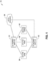
- a switch e.g., an Ethernet switch
- FIG. 1 an example communication network 50 is shown having an Ethernet switch 52 communicatively coupled between a data source 54 and three devices 56, 58, 60 in a network (illustrated as Device one, Device two, and Device three, respectively).
- a redundant Ethernet switch 62 may similarly be communicatively coupled between the data source 54 and the three devices 56, 58, 60, though not in direct communication with the Ethernet Switch 52.
- the redundant Ethernet switch 62 can provide network connectivity to each of the devices 56, 58, 60 should the Ethernet Switch 52 experience a failure, such as a power failure, a connectivity failure, a mechanical failure, and the like.
- the Ethernet switch 52 can provide network connectivity to each of the devices 56, 58, 60 should the redundant Ethernet Switch 62 experience a failure.
- such a configuration leads to a dependence on the devices to the functionality of each Ethernet switch.
- the Ethernet switches may not be optimized for their network functionality, such as by providing more ports than necessary, resulting in an inefficient use of the switches and the resources needed to provide the switches.
- communication network architectures employ one or more multi-port network switches within each device of a plurality of devices of the network, where a switch of a device is communicatively coupled with another switch of another device of the network.
- a multi-port network switch of a device can be communicatively coupled to a redundant switch of the same device.
- At least one switch of a device of the network is connected to a data source and/or data receiver (e.g., a control point, a router, a cloud, and so forth).
- a multi-port switch and/or a redundant multi-port switch of the same device may be connected to the data source/receiver.
- the multi-port network switches include three ports.
- the multi-port network switches include four ports. Accordingly, the disclosed communication network architectures may provide a network hopping architecture that provides efficient usage of each port of the multi-port network switches. For example, where the multi-port network switches are Ethernet switches, such communication network architectures may provide a hopping Ethernet architecture. Further, the disclosed communication network architectures may not depend on the functionality of one or two network switches connected to each of the devices, rather, each of the distributed network switches can utilize the infrastructure/resources (e.g., power) of the device supporting the switch, which can provide a robust communication network architecture.
- the infrastructure/resources e.g., power
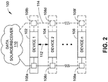
- the communication network architecture 100 includes a plurality of network devices 102, 104, 106 (illustrated as Device 1, Device 2, and Device n, respectively).
- the devices 102, 104, and 106 are physically distributed modules (e.g., distinct modules). While three devices are illustrated, the plurality of devices can include any number of devices, where "n" refers to the final device of the plurality of devices. Further, the second device and Device "n" could be the same device, such that the communication network architecture 100 includes two devices.
- the devices 102, 104, 106 can include any device configured for network communication and operation.
- the devices 102, 104, 106 can be a control module, an input/output (I/O) module, a power module, and so forth, such as incorporated in an industrial control system (ICS) (e.g., a secure industrial control system).
- ICS industrial control system
- the term "industrial control system” as used herein may encompass several types of control systems used in industrial production, including process control systems (PCS), supervisory control and data acquisition (SCADA) systems, distributed control systems (DCS), and other smaller control system configurations such as programmable logic controllers (PLC) often found in the industrial sectors and critical infrastructures.
- PCS process control systems
- SCADA supervisory control and data acquisition
- DCS distributed control systems
- PLC programmable logic controllers
- the devices 102, 104, 106 can be incorporated by an industrial control system to be implemented in a variety of industries, such as electrical, water, oil, gas, data, and so forth.
- automated or operator-driven supervisory commands can be transmitted to the devices 102, 104, 106 (which may include remote station control devices, field devices, and the like) of an industrial control system.
- the devices 102, 104, 106 as part of an industrial control system can control local operations such as opening and closing valves and breakers, collecting data from sensor systems, monitoring the local environment for alarm conditions, and performing other tasks germane to the design of the system.
- SCADA systems can be used with industrial processes, including manufacturing, production, power generation, fabrication, and refining.
- SCADA system can also be used with infrastructure processes, including water treatment and distribution, wastewater collection and treatment, oil and gas pipelines, electrical power transmission and distribution, wind farms, large communication systems, and so forth.
- SCADA systems can be used in facility processes for buildings, airports, ships, space stations, and the like (e.g., to monitor and control Heating, Ventilation, and Air Conditioning (HVAC) equipment and energy consumption).
- DCS systems are generally used in large campus industrial process plants, such as oil and gas, refining, chemical, pharmaceutical, food and beverage, water and wastewater, pulp and paper, utility power, mining, metals, and so forth.
- PLCs are typically used in industrial sectors and with critical infrastructures.
- each device e.g., devices 102, 104, 106 includes one or more (e.g., one switch, two switches, three switches, and so forth) integrated multi-port switches 108 (e.g., multi-port switch chips) configured to route data to/from a data source/receiver 110 and/or between the devices.
- multi-port switches 108 e.g., multi-port switch chips
- FIGS. 2 and 3 when a second multi-port switch is integrated by a particular device, the multi-port switches 108 of that device may provide redundant connections to facilitate robustness.
- the data source/receiver 110 can be a control point, a node, a router, a cloud, and so forth, configured to furnish or receive data (e.g., a command prompt, data request, etc.) to/from one or more of the devices 102, 104, 106.
- each port of the multi-port switches 108 integrated in the devices 102, 104, 106 includes a connection to a portion of the device (e.g., to a processing module, a power module, an I/O module, and so forth) that integrates the multi-port switch 108 and to one other port of another multi-port switch 108 in another device.
- One or more of the multi-port switches 108 can be a minimal propagation switch chip, such that the switch is configured to recognize that a data packet is not destined for the device integrating the switch, and to subsequently forward that data packet to another switch.
- each multi-port switch may differ depending on the device which integrates the switch.
- the devices may be designated as an initial switch (i.e., a switch connected between the data source/receiver 110 and an intermediary switch), an intermediary switch (i.e., a switch connected between an initial switch and another intermediary switch, a switch connected between an initial switch and a terminal switch, a switch connected between two intermediary switches, or a switch connected between another intermediary switch and a terminal switch), or a terminal switch (i.e., the switches of the final device of the plurality of devices with respect to the data source/receiver 110).
- an initial switch i.e., a switch connected between the data source/receiver 110 and an intermediary switch
- an intermediary switch i.e., a switch connected between an initial switch and another intermediary switch, a switch connected between an initial switch and a terminal switch, a switch connected between two intermediary switches, or a switch connected between another intermediary switch and a terminal switch
- the multi-port switches 108 designated as initial switches and as intermediary switches are three-port switches, whereas the terminal switches are two-port switches.
- One port of each switch is configured as a connection to a portion of the device (e.g., to a processing module, a power module, an I/O module, and so forth) that integrates the multi-port switch 108.
- One or more ports are configured as a connection to another switch on another device. As shown in FIG.
- the switches of device 1 may be designated as initial switches, since each switch includes a connection to the data source/receiver 110 and a switch of an intermediary switch (i.e., switch 108a includes a connection to switch 108c of device 2, and switch 108b, when present, includes a connection to switch 108d, when present, of device 2).
- the switches of device 2 may be designated as intermediary switches, since each switch includes a connection to an initial switch (i.e., switch 108c includes a connection to switch 108a of device 1, and switch 108d, when present, includes a connection to switch 108b, when present, of device 1) and a connection to a switch of device n or to a switch of another device, depending on whether device n is third (and terminal) device or a subsequent (and intermediary) device.
- the switch(es) of device 2 would include connections between the initial switch(es) of device 1 (described above) and intermediary switch(es) of an intervening device. If no devices intervene between device 2 and device n, then each switch of device 2 includes a connection to the initial switch(es) of device 1 (described above) and a connection to a terminal switch (i.e., switch 108c includes a connection to switch 108e of device n, and switch 108d, when present, includes a connection to switch 108f, when present, of device n).
- the switches of device n may be configured as two-port switches, designated as terminal switches, since each switch includes one connection to another switch on another device (i.e., switch 108e includes a connection to switch 108c of device 2 if no intermediary switches are present, or a connection to the switch of an intermediary switch, and switch 108f, when present, includes a connection to switch 108d, when present, of device 2 if no intermediary switches are present, or a connection to the switch of an intermediary switch), and one connection between the integrated switch and the device that integrates the switch.
- switch 108e includes a connection to switch 108c of device 2 if no intermediary switches are present, or a connection to the switch of an intermediary switch
- switch 108f when present, includes a connection to switch 108d, when present, of device 2 if no intermediary switches are present, or a connection to the switch of an intermediary switch
- the devices 102, 104, 106 may include an interlink (e.g., a dedicated private interlink) between the devices a form (e.g., another form of redundancy where multiple multi-port switches are integrated by each device) of redundancy between the devices.
- an interlink e.g., a dedicated private interlink
- device 1 (102) and device 2 (104) include an interlink 112 as a dedicated connection between the devices.
- one or more of the interlink 112 and a connection between multi-port switches 108 between two devices is implemented as a public interlink to provide distributed redundancy to the communication network architecture 100.
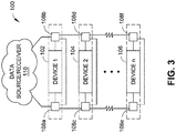
- the multi-port switches 108 designated as initial switches and as intermediary switches are four-port switches, whereas the terminal switches are three-port switches. Similar to the implementations with the three-port and two-port switches, one port of each switch is configured as a connection to a portion of the device (e.g., to a processing module, a power module, an I/O module, and so forth) that integrates the multi-port switch 108. One or more ports are configured as a connection to another switch on another device. Additionally, one port is configured as a connection to another (e.g., redundant) switch integrated by the same device. Referring to FIG.
- switches 108 are configured as four-port or three-port switches.
- the connectivity of the switches is similar to the architecture provided in FIG. 2 with redundant switches, however, each switch in FIG. 3 includes one additional connection.
- switches 108a and 108b are four-port switches that include a connection between each other.
- Switches 108c and 108d are four-port switches that include a connection between each other.
- Switches 108e and 108f are three-port switches that include a connection between each other.
- the direct connection between switches integrated by the same device may facilitate robust network connectivity, even when the device experiences interruptions in service.
- the connections between switches and devices may provide communicative coupling via communication links to facilitate communication and/or power signal transmission.
- the devices 102, 104, 106 may be configured as field devices, which may include an input instrument, such as a sensor, which can be used for functions such as measuring pressure in piping for a gas plant, a refinery, and so forth.
- input modules of the device input/output modules can be used to receive information from input instruments, such as the sensor, in the process or the field.
- the input/output modules may be configured to convert analog data received from the sensor of the field device to digital data (e.g., using Analog-to-Digital Converter (ADC) circuitry, and so forth).
- the devices may include power modules configured to supply electrical power to the field devices, such as via input/output modules.
- the input/output modules of the devices when configured as output modules, can be used to transmit instructions to output instruments of the field devices.
- the field devices may include an output instrument, such as a motor.
- the input/output modules may be connected to the motor and configured to control one or more operating characteristics of the motor, such as motor speed, motor torque, and so forth.
- the input/output modules may be configured to convert digital data to analog data for transmission to the motor (e.g., using Digital-to-Analog (DAC) circuitry, and so forth).
- DAC Digital-to-Analog
- one or more of the input/output modules may include a communications module configured for communicating via a communications sub-bus, such as an Ethernet bus, an HI field bus, a Process Field Bus (PROFIBUS), a Highway Addressable Remote Transducer (HART) bus, a Modbus, and so forth.
- a communications sub-bus such as an Ethernet bus, an HI field bus, a Process Field Bus (PROFIBUS), a Highway Addressable Remote Transducer (HART) bus, a Modbus, and so forth.
- the switches 108 may be configured as two-port Ethernet switch chips, three-port Ethernet switch chips, or four-port Ethernet switch chips, depending on the communication network architecture.
- the devices 102, 104, 106 may include input/output modules configured to collect data and control systems in applications including, but not necessarily limited to: industrial processes, such as manufacturing, production, power generation, fabrication, and refining; infrastructure processes, such as water treatment and distribution, wastewater collection and treatment, oil and gas pipelines, electrical power transmission and distribution, wind farms, and large communication systems; facility processes for buildings, airports, ships, and space stations (e.g., to monitor and control Heating, Ventilation, and Air Conditioning (HVAC) equipment and energy consumption); large campus industrial process plants, such as oil and gas, refining, chemical, pharmaceutical, food and beverage, water and wastewater, pulp and paper, utility power, mining, metals; and/or critical infrastructures.
- industrial processes such as manufacturing, production, power generation, fabrication, and refining
- infrastructure processes such as water treatment and distribution, wastewater collection and treatment, oil and gas pipelines, electrical power transmission and distribution, wind farms, and large communication systems
- facility processes for buildings, airports, ships, and space stations (e.g., to monitor
- the switches 108 include multiple ports that furnish a physical connection to hardware and circuitry included with the devices 102, 104, 106, such as a printed circuit board (PCB), and so forth.
- the devices 102, 104, 106 may also include an interface for connecting to other networks, including but not necessarily limited to: a wide-area cellular telephone network, such as a 3G cellular network, a 4G cellular network, or a Global System for Mobile communications (GSM) network; a wireless computer communications network, such as a Wi-Fi network (e.g., a Wireless LAN (WLAN) operated using IEEE 802.11 network standards); a Personal Area Network (PAN) (e.g., a Wireless PAN (WPAN) operated using IEEE 802.15 network standards); a Wide Area Network (WAN); an intranet; an extranet; an internet; the Internet; and so on.
- the devices 102, 104, 106 may further include a connection for connecting the devices 102, 104, 106 to a computer bus, and
- Data transmitted between communication connections may be packetized (e.g., discrete portions of the data may be converted into data packets comprising the data portions along with network control information, and so forth).
- the communication network may use one or more protocols for data transmission, including a bit-oriented synchronous data link layer protocol such as High-Level Data Link Control (HDLC).
- HDLC High-Level Data Link Control
- the communication network and/or the communication connections may implement HDLC according to an International Organization for Standardization (ISO) 13239 standard, or the like.
- ISO International Organization for Standardization
- HDLC is provided by way of example only and is not meant to be restrictive of the present disclosure.
- the communication network may use other various communications protocols in accordance with the present disclosure.
- the communication connections may be configured for exchanging information with components used for monitoring and/or controlling instrumentation, such as one or more control loop feedback mechanisms/controllers.
- a controller can be configured as a microcontroller/Programmable Logic Controller (PLC), a Proportional-Integral-Derivative (PID) controller, and so forth.
- PLC microcontroller/Programmable Logic Controller
- PID Proportional-Integral-Derivative
- One or more of devices 102, 104, 106 may include a network interface for connecting to a controller via a network.
- the network interface may be configured as a Gigabit Ethernet interface.
- the network interface may be configured for connecting the devices 102, 104, 106 to other various networks, including but not necessarily limited to: a wide-area cellular telephone network, such as a 3G cellular network, a 4G cellular network, or a Global System for Mobile communications (GSM) network; a wireless computer communications network, such as a Wi-Fi network (e.g., a Wireless LAN (WLAN) operated using IEEE 802.11 network standards); a Personal Area Network (PAN) (e.g., a Wireless PAN (WPAN) operated using IEEE 802.15 network standards); a Wide Area Network (WAN); an intranet; an extranet; an internet; the Internet; and so on.
- a wide-area cellular telephone network such as a 3G cellular network, a 4G cellular network, or a Global System for Mobile communications (GSM) network
- GSM Global System for Mobile communications
- Wi-Fi network e.g., a Wireless LAN (WLAN) operated using IEEE 802.11 network standards
- the network interface may be implemented using computer bus.
- the network interface can include a Peripheral Component Interconnect (PCI) card interface, such as a Mini PCI interface, and so forth.
- PCI Peripheral Component Interconnect
- the network may be configured to include a single network or multiple networks across different access points.
- the devices 102, 104, 106 may include one or more of the power modules that can include an AC-to-DC (AC/DC) converter for converting Alternating Current (AC) (e.g., as supplied by AC mains, and so forth) to Direct Current (DC) for transmission to a field device, such as a motor (e.g., in an implementation where the motor comprises a DC motor).
- AC Alternating Current
- DC Direct Current
- a field device such as a motor
- Two or more power modules can be used to provide redundancy.
- two power modules can be connected to or implemented in one or more of the devices 102, 104, 106 using a separate (e.g., redundant) power backplane for each power module.
- the power backplane(s) may be connected to one or more input/output modules using connectors/connector assemblies.
- the multi-port switches 108 may be integrated by the devices 102, 104, 106 using a support frame.
- the support frame may be used to support and/or interconnect communications control modules, power modules, communication connections, power backplane(s), and/or input/output modules.
- one or more communications modules may be comprised of a circuit board.
- the circuit board may be mounted to the support frame.
- the connectors may be mounted to the support frame.
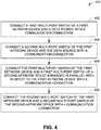
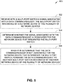
- the method 400 includes connecting a first multi-port switch of a first network device and a data source with a communication connection (Block 402).
- multi-port switch 108a of device 1 is connected to the data source/receiver 110.
- the method 400 also includes connecting a second multi-port switch of the first network device and the data source with a communication connection (Block 404).
- multi-port switch 108b of device 1 is connected to the data source/receiver 110.
- the method 400 further includes connecting the first multi-port switch of a first network device and a first multi-port switch of a second network device arranged in parallel with respect to the first network device with a communication connection (Block 406).
- multi-port switch 108a of device 1 (102) is connected to multi-port switch 108c of device 2 (104).
- the method 400 further includes connecting the second multi-port switch of the first network device and a second multi-port switch of the second network device with a communication connection (Block 408).
- multi-port switch 108b of device 1 (102) is connected to multi-port switch 108d of device 2 (104).
- the method 500 includes receiving with a multi-port switch a signal associated with a data command/request, the multi-port switch integrated by a network device of the plurality of network devices (Block 502).
- multi-port switch 108a of device 1 (102) may receive a data request from the data source/receiver 110.
- the data request may involve data associated with any of the devices 102, 104, 106.
- the method 500 also includes determining whether the signal associated with the data command/request is designated for the network device that integrates the multi-port switch (Block 504).
- the multi-port switches 108 e.g., multi-port switch 108a
- the method 500 further includes, when it is determined that the data command/request is not designated for the network device that integrates the multi-port switch, forwarding the data command/request to another multi-port switch integrated by another network device of the plurality of network devices (Block 506).
- multi-port switch 108a determines that the data command/request from the data source/receiver 110 is not designated for device 1 (102), then the multi-port switch 108a forwards the data command/request to multi-port switch 108c of device 2 (104).
- the pattern of recognition and forwarding e.g., hopping
- any of the functions described herein can be implemented using hardware (e.g., fixed logic circuitry such as integrated circuits), software, firmware, manual processing, or a combination thereof.
- the blocks discussed in the above disclosure generally represent hardware (e.g., fixed logic circuitry such as integrated circuits), software, firmware, or a combination thereof.
- the various blocks discussed in the above disclosure may be implemented as integrated circuits along with other functionality. Such integrated circuits may include all of the functions of a given block, system, or circuit, or a portion of the functions of the block, system or circuit. Further, elements of the blocks, systems, or circuits may be implemented across multiple integrated circuits.
- Such integrated circuits may comprise various integrated circuits including, but not necessarily limited to: a monolithic integrated circuit, a flip chip integrated circuit, a multichip module integrated circuit, and/or a mixed signal integrated circuit.
- the various blocks discussed in the above disclosure represent executable instructions (e.g., program code) that perform specified tasks when executed on a processor. These executable instructions can be stored in one or more tangible computer readable media.
- the entire system, block or circuit may be implemented using its software or firmware equivalent.
- one part of a given system, block or circuit may be implemented in software or firmware, while other parts are implemented in hardware.
Landscapes
- Engineering & Computer Science (AREA)
- Computer Networks & Wireless Communication (AREA)
- Signal Processing (AREA)
- Health & Medical Sciences (AREA)
- Computing Systems (AREA)
- General Health & Medical Sciences (AREA)
- Medical Informatics (AREA)
- Small-Scale Networks (AREA)
- Data Exchanges In Wide-Area Networks (AREA)
Applications Claiming Priority (2)
| Application Number | Priority Date | Filing Date | Title |
|---|---|---|---|
| US201461940089P | 2014-02-14 | 2014-02-14 | |
| US14/449,722 US9647961B2 (en) | 2014-02-14 | 2014-08-01 | Communication network hopping architecture |
Publications (2)
| Publication Number | Publication Date |
|---|---|
| EP2908488A1 EP2908488A1 (en) | 2015-08-19 |
| EP2908488B1 true EP2908488B1 (en) | 2018-04-11 |
Family
ID=52469695
Family Applications (1)
| Application Number | Title | Priority Date | Filing Date |
|---|---|---|---|
| EP15155105.8A Active EP2908488B1 (en) | 2014-02-14 | 2015-02-13 | Multi port switches |
Country Status (4)
| Country | Link |
|---|---|
| US (4) | US9647961B2 (enExample) |
| EP (1) | EP2908488B1 (enExample) |
| JP (3) | JP6651290B2 (enExample) |
| CN (1) | CN104852839B (enExample) |
Families Citing this family (5)
| Publication number | Priority date | Publication date | Assignee | Title |
|---|---|---|---|---|
| FR3034601A1 (fr) * | 2015-03-31 | 2016-10-07 | Thales Sa | Reseau de communication, installation de communication a bord d'un aeronef et aeronef comprenant une telle installation de communication |
| US10296515B2 (en) | 2016-06-09 | 2019-05-21 | Honeywell International Inc. | Engineering data collection from control and instrumentation systems |
| CA3155694A1 (en) | 2019-09-24 | 2021-04-01 | Genetec Inc. | Intermediary device for daisy chain and tree configuration in hybrid data/power connection |
| US11770155B2 (en) * | 2020-05-19 | 2023-09-26 | Genetec Inc. | Power distribution and data routing in a network of devices interconnected by hybrid data/power links |
| JP2023033850A (ja) * | 2021-08-30 | 2023-03-13 | 日鉄テックスエンジ株式会社 | ネットワークシステム及び情報処理装置 |
Family Cites Families (37)
| Publication number | Priority date | Publication date | Assignee | Title |
|---|---|---|---|---|
| US5550816A (en) * | 1994-12-29 | 1996-08-27 | Storage Technology Corporation | Method and apparatus for virtual switching |
| US6236643B1 (en) * | 1997-02-14 | 2001-05-22 | Advanced Micro Devices, Inc. | Multiport data switch having variable maximum packet length |
| FR2779892B1 (fr) | 1998-06-15 | 2000-07-13 | Alsthom Cge Alcatel | Systeme de transfert de donnees entre stations multiples |
| US6308282B1 (en) * | 1998-11-10 | 2001-10-23 | Honeywell International Inc. | Apparatus and methods for providing fault tolerance of networks and network interface cards |
| US6414958B1 (en) * | 1998-11-30 | 2002-07-02 | Electronic Data Systems Corporation | Four-port secure ethernet VLAN switch supporting SNMP and RMON |
| US6282145B1 (en) | 1999-01-14 | 2001-08-28 | Silicon Storage Technology, Inc. | Array architecture and operating methods for digital multilevel nonvolatile memory integrated circuit system |
| JP2001111616A (ja) | 1999-10-07 | 2001-04-20 | Nec Corp | 蓄積交換スイッチおよび蓄積交換方法 |
| CA2408342A1 (en) * | 2000-05-05 | 2001-11-15 | Hill-Rom Services, Inc. | Remote control for a hospital bed |
| US6904477B2 (en) * | 2001-04-13 | 2005-06-07 | Sun Microsystems, Inc. | Virtual host controller interface with multipath input/output |
| JP2003069592A (ja) | 2001-08-23 | 2003-03-07 | Fujikura Ltd | スイッチングハブの制御回路及びスイッチングハブ |
| US7385919B2 (en) * | 2002-02-22 | 2008-06-10 | Siemens Aktiengesellschaft | Local network, particularly Ethernet network having redundancy properties, and coupling device for such a network |
| US7221911B2 (en) | 2002-08-16 | 2007-05-22 | Wisair Ltd. | Multi-band ultra-wide band communication method and system |
| US7289537B1 (en) * | 2002-11-01 | 2007-10-30 | Greenfield Networks, Inc. | Single-chip multi-port Ethernet switch |
| JP2004320477A (ja) | 2003-04-16 | 2004-11-11 | Canon Inc | ネットワークシステムの制御方法 |
| US20060039338A1 (en) | 2004-08-18 | 2006-02-23 | Mike Kwon | Integration of a wireless wide-area network (WAN) data terminal with a network processor for interfacing with local-area network (LAN) nodes |
| US7433302B2 (en) | 2005-05-04 | 2008-10-07 | Micrel, Inc. | Ethernet network implementing redundancy using a single category 5 cable |
| FI20055363L (fi) * | 2005-06-29 | 2006-12-30 | Abb Oy | Reduntanttinen automaatiotietoliikenneverkko |
| US20070025240A1 (en) * | 2005-07-29 | 2007-02-01 | Snide Todd A | Bypass switch for an ethernet device and method of bypassing devices in an ethernet network |
| US7739432B1 (en) | 2005-09-02 | 2010-06-15 | Pmc-Sierra, Inc. | Command switching for multiple initiator access to a SATA drive |
| US8730834B2 (en) * | 2005-12-23 | 2014-05-20 | General Electric Company | Intelligent electronic device with embedded multi-port data packet controller |
| US7817538B2 (en) * | 2006-09-13 | 2010-10-19 | Rockwell Automation Technologies, Inc. | Fault-tolerant Ethernet network |
| US20080126572A1 (en) * | 2006-10-05 | 2008-05-29 | Holt John M | Multi-path switching networks |
| US7917713B2 (en) | 2006-12-20 | 2011-03-29 | International Business Machines Corporation | Optimized data migration with a support processor |
| US7925793B2 (en) | 2007-05-31 | 2011-04-12 | Ixia | Reconfigurable test system |
| GB0814556D0 (en) | 2008-08-11 | 2008-09-17 | Edwards Ltd | Purification of gas stream |
| WO2010105828A1 (de) * | 2009-03-18 | 2010-09-23 | Hirschmann Automation And Control Gmbh | Parallelbetrieb von rstp (rapid spanning tree protocol) und mrp (media redundancy protocol) und segmentierung/kopplung |
| US8964795B2 (en) | 2009-06-01 | 2015-02-24 | Achronix Semiconductor Corporation | Asynchronous pipelined interconnect architecture with fanout support |
| US8886746B2 (en) * | 2009-09-09 | 2014-11-11 | Rockwell Automation Technologies, Inc. | Diagnostic module for distributed industrial network including industrial control devices |
| JP5458863B2 (ja) * | 2009-10-28 | 2014-04-02 | 富士電機株式会社 | データ伝送装置及びデータ伝送方法 |
| US8582423B2 (en) * | 2010-08-04 | 2013-11-12 | Alcatel Lucent | Multi-chassis inter-process communication |
| US20140185427A1 (en) * | 2011-06-30 | 2014-07-03 | Schneider Electric Industries Sas | Dual-ring switch for rstp networks |
| DE102011082965A1 (de) * | 2011-09-19 | 2013-01-24 | Siemens Aktiengesellschaft | Verfahren zum Betreiben einer Netzwerkanordnung und Netzwerkanordnung |
| US8842664B2 (en) * | 2011-09-27 | 2014-09-23 | Znyx Networks, Inc. | Chassis management modules for advanced telecom computing architecture shelves, and methods for using the same |
| US8670303B2 (en) * | 2011-10-05 | 2014-03-11 | Rockwell Automation Technologies, Inc. | Multiple-fault-tolerant ethernet network for industrial control |
| CN102347865B (zh) * | 2011-11-04 | 2015-02-25 | 华为技术有限公司 | 一种以太网环路定位方法、交换设备及系统 |
| US8964772B2 (en) * | 2012-10-09 | 2015-02-24 | Broadcom Corporation | Method for implementing a multi-chip module with a high-rate interface |
| JP5874608B2 (ja) * | 2012-11-08 | 2016-03-02 | 日立金属株式会社 | 通信システムおよびネットワーク中継装置 |
-
2014
- 2014-08-01 US US14/449,722 patent/US9647961B2/en active Active
-
2015
- 2015-02-09 JP JP2015022995A patent/JP6651290B2/ja active Active
- 2015-02-12 CN CN201510075356.6A patent/CN104852839B/zh active Active
- 2015-02-13 EP EP15155105.8A patent/EP2908488B1/en active Active
-
2017
- 2017-05-04 US US15/586,410 patent/US10313273B2/en active Active
-
2019
- 2019-06-03 US US16/429,783 patent/US11201837B2/en active Active
- 2019-08-13 JP JP2019148431A patent/JP7221828B2/ja active Active
-
2021
- 2021-12-14 US US17/550,460 patent/US11876733B2/en active Active
-
2022
- 2022-11-04 JP JP2022177265A patent/JP7637097B2/ja active Active
Non-Patent Citations (1)
| Title |
|---|
| None * |
Also Published As
| Publication number | Publication date |
|---|---|
| US20170302594A1 (en) | 2017-10-19 |
| JP7221828B2 (ja) | 2023-02-14 |
| CN104852839A (zh) | 2015-08-19 |
| US20150236981A1 (en) | 2015-08-20 |
| US11201837B2 (en) | 2021-12-14 |
| JP2020017962A (ja) | 2020-01-30 |
| US11876733B2 (en) | 2024-01-16 |
| CN104852839B (zh) | 2020-01-31 |
| JP2015159535A (ja) | 2015-09-03 |
| EP2908488A1 (en) | 2015-08-19 |
| JP6651290B2 (ja) | 2020-02-19 |
| US10313273B2 (en) | 2019-06-04 |
| US20190372912A1 (en) | 2019-12-05 |
| JP7637097B2 (ja) | 2025-02-27 |
| US9647961B2 (en) | 2017-05-09 |
| JP2023011861A (ja) | 2023-01-24 |
| US20220182336A1 (en) | 2022-06-09 |
Similar Documents
| Publication | Publication Date | Title |
|---|---|---|
| US11876733B2 (en) | Communication network hopping architecture | |
| US10896145B2 (en) | Communications control system with a serial communications interface and a parallel communications interface | |
| US12019575B2 (en) | Switch fabric having a serial communications interface and a parallel communications interface | |
| US9436641B2 (en) | Switch fabric having a serial communications interface and a parallel communications interface | |
| US9779229B2 (en) | Secure industrial control system | |
| EP3030942B1 (en) | Secure industrial control system | |
| CN102478804A (zh) | 可编程逻辑控制器系统 | |
| US7617011B2 (en) | Automation system | |
| KR20150055131A (ko) | Tcp/ip 기반 스마트 나노―그리드에 적용을 위한 범용 통신 모듈 장치 및 그 방법 | |
| CN102571641A (zh) | 用于自动化连接的多个不同自动化系统的公共通信系统 |
Legal Events
| Date | Code | Title | Description |
|---|---|---|---|
| PUAI | Public reference made under article 153(3) epc to a published international application that has entered the european phase |
Free format text: ORIGINAL CODE: 0009012 |
|
| AK | Designated contracting states |
Kind code of ref document: A1 Designated state(s): AL AT BE BG CH CY CZ DE DK EE ES FI FR GB GR HR HU IE IS IT LI LT LU LV MC MK MT NL NO PL PT RO RS SE SI SK SM TR |
|
| AX | Request for extension of the european patent |
Extension state: BA ME |
|
| 17P | Request for examination filed |
Effective date: 20160219 |
|
| RBV | Designated contracting states (corrected) |
Designated state(s): AL AT BE BG CH CY CZ DE DK EE ES FI FR GB GR HR HU IE IS IT LI LT LU LV MC MK MT NL NO PL PT RO RS SE SI SK SM TR |
|
| 17Q | First examination report despatched |
Effective date: 20160315 |
|
| GRAP | Despatch of communication of intention to grant a patent |
Free format text: ORIGINAL CODE: EPIDOSNIGR1 |
|
| STAA | Information on the status of an ep patent application or granted ep patent |
Free format text: STATUS: GRANT OF PATENT IS INTENDED |
|
| INTG | Intention to grant announced |
Effective date: 20170922 |
|
| GRAJ | Information related to disapproval of communication of intention to grant by the applicant or resumption of examination proceedings by the epo deleted |
Free format text: ORIGINAL CODE: EPIDOSDIGR1 |
|
| STAA | Information on the status of an ep patent application or granted ep patent |
Free format text: STATUS: EXAMINATION IS IN PROGRESS |
|
| GRAR | Information related to intention to grant a patent recorded |
Free format text: ORIGINAL CODE: EPIDOSNIGR71 |
|
| GRAS | Grant fee paid |
Free format text: ORIGINAL CODE: EPIDOSNIGR3 |
|
| STAA | Information on the status of an ep patent application or granted ep patent |
Free format text: STATUS: GRANT OF PATENT IS INTENDED |
|
| INTC | Intention to grant announced (deleted) | ||
| INTG | Intention to grant announced |
Effective date: 20180130 |
|
| GRAA | (expected) grant |
Free format text: ORIGINAL CODE: 0009210 |
|
| STAA | Information on the status of an ep patent application or granted ep patent |
Free format text: STATUS: THE PATENT HAS BEEN GRANTED |
|
| AK | Designated contracting states |
Kind code of ref document: B1 Designated state(s): AL AT BE BG CH CY CZ DE DK EE ES FI FR GB GR HR HU IE IS IT LI LT LU LV MC MK MT NL NO PL PT RO RS SE SI SK SM TR |
|
| REG | Reference to a national code |
Ref country code: GB Ref legal event code: FG4D |
|
| REG | Reference to a national code |
Ref country code: CH Ref legal event code: EP |
|
| REG | Reference to a national code |
Ref country code: AT Ref legal event code: REF Ref document number: 989150 Country of ref document: AT Kind code of ref document: T Effective date: 20180415 |
|
| REG | Reference to a national code |
Ref country code: IE Ref legal event code: FG4D |
|
| REG | Reference to a national code |
Ref country code: DE Ref legal event code: R096 Ref document number: 602015009717 Country of ref document: DE |
|
| REG | Reference to a national code |
Ref country code: NL Ref legal event code: MP Effective date: 20180411 |
|
| REG | Reference to a national code |
Ref country code: LT Ref legal event code: MG4D |
|
| PG25 | Lapsed in a contracting state [announced via postgrant information from national office to epo] |
Ref country code: NL Free format text: LAPSE BECAUSE OF FAILURE TO SUBMIT A TRANSLATION OF THE DESCRIPTION OR TO PAY THE FEE WITHIN THE PRESCRIBED TIME-LIMIT Effective date: 20180411 |
|
| PG25 | Lapsed in a contracting state [announced via postgrant information from national office to epo] |
Ref country code: LT Free format text: LAPSE BECAUSE OF FAILURE TO SUBMIT A TRANSLATION OF THE DESCRIPTION OR TO PAY THE FEE WITHIN THE PRESCRIBED TIME-LIMIT Effective date: 20180411 Ref country code: SE Free format text: LAPSE BECAUSE OF FAILURE TO SUBMIT A TRANSLATION OF THE DESCRIPTION OR TO PAY THE FEE WITHIN THE PRESCRIBED TIME-LIMIT Effective date: 20180411 Ref country code: ES Free format text: LAPSE BECAUSE OF FAILURE TO SUBMIT A TRANSLATION OF THE DESCRIPTION OR TO PAY THE FEE WITHIN THE PRESCRIBED TIME-LIMIT Effective date: 20180411 Ref country code: NO Free format text: LAPSE BECAUSE OF FAILURE TO SUBMIT A TRANSLATION OF THE DESCRIPTION OR TO PAY THE FEE WITHIN THE PRESCRIBED TIME-LIMIT Effective date: 20180711 Ref country code: PL Free format text: LAPSE BECAUSE OF FAILURE TO SUBMIT A TRANSLATION OF THE DESCRIPTION OR TO PAY THE FEE WITHIN THE PRESCRIBED TIME-LIMIT Effective date: 20180411 Ref country code: AL Free format text: LAPSE BECAUSE OF FAILURE TO SUBMIT A TRANSLATION OF THE DESCRIPTION OR TO PAY THE FEE WITHIN THE PRESCRIBED TIME-LIMIT Effective date: 20180411 Ref country code: BG Free format text: LAPSE BECAUSE OF FAILURE TO SUBMIT A TRANSLATION OF THE DESCRIPTION OR TO PAY THE FEE WITHIN THE PRESCRIBED TIME-LIMIT Effective date: 20180711 Ref country code: FI Free format text: LAPSE BECAUSE OF FAILURE TO SUBMIT A TRANSLATION OF THE DESCRIPTION OR TO PAY THE FEE WITHIN THE PRESCRIBED TIME-LIMIT Effective date: 20180411 |
|
| PG25 | Lapsed in a contracting state [announced via postgrant information from national office to epo] |
Ref country code: RS Free format text: LAPSE BECAUSE OF FAILURE TO SUBMIT A TRANSLATION OF THE DESCRIPTION OR TO PAY THE FEE WITHIN THE PRESCRIBED TIME-LIMIT Effective date: 20180411 Ref country code: LV Free format text: LAPSE BECAUSE OF FAILURE TO SUBMIT A TRANSLATION OF THE DESCRIPTION OR TO PAY THE FEE WITHIN THE PRESCRIBED TIME-LIMIT Effective date: 20180411 Ref country code: GR Free format text: LAPSE BECAUSE OF FAILURE TO SUBMIT A TRANSLATION OF THE DESCRIPTION OR TO PAY THE FEE WITHIN THE PRESCRIBED TIME-LIMIT Effective date: 20180712 Ref country code: HR Free format text: LAPSE BECAUSE OF FAILURE TO SUBMIT A TRANSLATION OF THE DESCRIPTION OR TO PAY THE FEE WITHIN THE PRESCRIBED TIME-LIMIT Effective date: 20180411 |
|
| REG | Reference to a national code |
Ref country code: AT Ref legal event code: MK05 Ref document number: 989150 Country of ref document: AT Kind code of ref document: T Effective date: 20180411 |
|
| PG25 | Lapsed in a contracting state [announced via postgrant information from national office to epo] |
Ref country code: PT Free format text: LAPSE BECAUSE OF FAILURE TO SUBMIT A TRANSLATION OF THE DESCRIPTION OR TO PAY THE FEE WITHIN THE PRESCRIBED TIME-LIMIT Effective date: 20180813 |
|
| REG | Reference to a national code |
Ref country code: DE Ref legal event code: R097 Ref document number: 602015009717 Country of ref document: DE |
|
| PG25 | Lapsed in a contracting state [announced via postgrant information from national office to epo] |
Ref country code: AT Free format text: LAPSE BECAUSE OF FAILURE TO SUBMIT A TRANSLATION OF THE DESCRIPTION OR TO PAY THE FEE WITHIN THE PRESCRIBED TIME-LIMIT Effective date: 20180411 Ref country code: EE Free format text: LAPSE BECAUSE OF FAILURE TO SUBMIT A TRANSLATION OF THE DESCRIPTION OR TO PAY THE FEE WITHIN THE PRESCRIBED TIME-LIMIT Effective date: 20180411 Ref country code: DK Free format text: LAPSE BECAUSE OF FAILURE TO SUBMIT A TRANSLATION OF THE DESCRIPTION OR TO PAY THE FEE WITHIN THE PRESCRIBED TIME-LIMIT Effective date: 20180411 Ref country code: SK Free format text: LAPSE BECAUSE OF FAILURE TO SUBMIT A TRANSLATION OF THE DESCRIPTION OR TO PAY THE FEE WITHIN THE PRESCRIBED TIME-LIMIT Effective date: 20180411 Ref country code: RO Free format text: LAPSE BECAUSE OF FAILURE TO SUBMIT A TRANSLATION OF THE DESCRIPTION OR TO PAY THE FEE WITHIN THE PRESCRIBED TIME-LIMIT Effective date: 20180411 Ref country code: CZ Free format text: LAPSE BECAUSE OF FAILURE TO SUBMIT A TRANSLATION OF THE DESCRIPTION OR TO PAY THE FEE WITHIN THE PRESCRIBED TIME-LIMIT Effective date: 20180411 |
|
| PLBE | No opposition filed within time limit |
Free format text: ORIGINAL CODE: 0009261 |
|
| STAA | Information on the status of an ep patent application or granted ep patent |
Free format text: STATUS: NO OPPOSITION FILED WITHIN TIME LIMIT |
|
| PG25 | Lapsed in a contracting state [announced via postgrant information from national office to epo] |
Ref country code: IT Free format text: LAPSE BECAUSE OF FAILURE TO SUBMIT A TRANSLATION OF THE DESCRIPTION OR TO PAY THE FEE WITHIN THE PRESCRIBED TIME-LIMIT Effective date: 20180411 Ref country code: SM Free format text: LAPSE BECAUSE OF FAILURE TO SUBMIT A TRANSLATION OF THE DESCRIPTION OR TO PAY THE FEE WITHIN THE PRESCRIBED TIME-LIMIT Effective date: 20180411 |
|
| 26N | No opposition filed |
Effective date: 20190114 |
|
| PG25 | Lapsed in a contracting state [announced via postgrant information from national office to epo] |
Ref country code: SI Free format text: LAPSE BECAUSE OF FAILURE TO SUBMIT A TRANSLATION OF THE DESCRIPTION OR TO PAY THE FEE WITHIN THE PRESCRIBED TIME-LIMIT Effective date: 20180411 |
|
| REG | Reference to a national code |
Ref country code: CH Ref legal event code: PL |
|
| PG25 | Lapsed in a contracting state [announced via postgrant information from national office to epo] |
Ref country code: LU Free format text: LAPSE BECAUSE OF NON-PAYMENT OF DUE FEES Effective date: 20190213 Ref country code: MC Free format text: LAPSE BECAUSE OF FAILURE TO SUBMIT A TRANSLATION OF THE DESCRIPTION OR TO PAY THE FEE WITHIN THE PRESCRIBED TIME-LIMIT Effective date: 20180411 |
|
| REG | Reference to a national code |
Ref country code: BE Ref legal event code: MM Effective date: 20190228 |
|
| REG | Reference to a national code |
Ref country code: IE Ref legal event code: MM4A |
|
| PG25 | Lapsed in a contracting state [announced via postgrant information from national office to epo] |
Ref country code: CH Free format text: LAPSE BECAUSE OF NON-PAYMENT OF DUE FEES Effective date: 20190228 Ref country code: LI Free format text: LAPSE BECAUSE OF NON-PAYMENT OF DUE FEES Effective date: 20190228 |
|
| PG25 | Lapsed in a contracting state [announced via postgrant information from national office to epo] |
Ref country code: IE Free format text: LAPSE BECAUSE OF NON-PAYMENT OF DUE FEES Effective date: 20190213 |
|
| PG25 | Lapsed in a contracting state [announced via postgrant information from national office to epo] |
Ref country code: BE Free format text: LAPSE BECAUSE OF NON-PAYMENT OF DUE FEES Effective date: 20190228 |
|
| PG25 | Lapsed in a contracting state [announced via postgrant information from national office to epo] |
Ref country code: TR Free format text: LAPSE BECAUSE OF FAILURE TO SUBMIT A TRANSLATION OF THE DESCRIPTION OR TO PAY THE FEE WITHIN THE PRESCRIBED TIME-LIMIT Effective date: 20180411 |
|
| PG25 | Lapsed in a contracting state [announced via postgrant information from national office to epo] |
Ref country code: MT Free format text: LAPSE BECAUSE OF NON-PAYMENT OF DUE FEES Effective date: 20190213 |
|
| PG25 | Lapsed in a contracting state [announced via postgrant information from national office to epo] |
Ref country code: CY Free format text: LAPSE BECAUSE OF FAILURE TO SUBMIT A TRANSLATION OF THE DESCRIPTION OR TO PAY THE FEE WITHIN THE PRESCRIBED TIME-LIMIT Effective date: 20180411 |
|
| PG25 | Lapsed in a contracting state [announced via postgrant information from national office to epo] |
Ref country code: IS Free format text: LAPSE BECAUSE OF FAILURE TO SUBMIT A TRANSLATION OF THE DESCRIPTION OR TO PAY THE FEE WITHIN THE PRESCRIBED TIME-LIMIT Effective date: 20180811 |
|
| PG25 | Lapsed in a contracting state [announced via postgrant information from national office to epo] |
Ref country code: HU Free format text: LAPSE BECAUSE OF FAILURE TO SUBMIT A TRANSLATION OF THE DESCRIPTION OR TO PAY THE FEE WITHIN THE PRESCRIBED TIME-LIMIT; INVALID AB INITIO Effective date: 20150213 |
|
| REG | Reference to a national code |
Ref country code: DE Ref legal event code: R079 Ref document number: 602015009717 Country of ref document: DE Free format text: PREVIOUS MAIN CLASS: H04L0012933000 Ipc: H04L0049100000 |
|
| PG25 | Lapsed in a contracting state [announced via postgrant information from national office to epo] |
Ref country code: MK Free format text: LAPSE BECAUSE OF FAILURE TO SUBMIT A TRANSLATION OF THE DESCRIPTION OR TO PAY THE FEE WITHIN THE PRESCRIBED TIME-LIMIT Effective date: 20180411 |
|
| P01 | Opt-out of the competence of the unified patent court (upc) registered |
Effective date: 20230521 |
|
| REG | Reference to a national code |
Ref country code: GB Ref legal event code: 732E Free format text: REGISTERED BETWEEN 20240314 AND 20240320 |
|
| PGFP | Annual fee paid to national office [announced via postgrant information from national office to epo] |
Ref country code: GB Payment date: 20260121 Year of fee payment: 12 |
|
| PGFP | Annual fee paid to national office [announced via postgrant information from national office to epo] |
Ref country code: DE Payment date: 20260121 Year of fee payment: 12 |
|
| PGFP | Annual fee paid to national office [announced via postgrant information from national office to epo] |
Ref country code: FR Payment date: 20260121 Year of fee payment: 12 |