EP2908075B1 - Refrigerator - Google Patents
Refrigerator Download PDFInfo
- Publication number
- EP2908075B1 EP2908075B1 EP14197543.3A EP14197543A EP2908075B1 EP 2908075 B1 EP2908075 B1 EP 2908075B1 EP 14197543 A EP14197543 A EP 14197543A EP 2908075 B1 EP2908075 B1 EP 2908075B1
- Authority
- EP
- European Patent Office
- Prior art keywords
- connector
- water
- disposed
- bracket
- heads
- Prior art date
- Legal status (The legal status is an assumption and is not a legal conclusion. Google has not performed a legal analysis and makes no representation as to the accuracy of the status listed.)
- Active
Links
- XLYOFNOQVPJJNP-UHFFFAOYSA-N water Substances O XLYOFNOQVPJJNP-UHFFFAOYSA-N 0.000 claims description 180
- 238000010168 coupling process Methods 0.000 claims description 38
- 230000008878 coupling Effects 0.000 claims description 35
- 238000005859 coupling reaction Methods 0.000 claims description 35
- 239000008213 purified water Substances 0.000 claims description 24
- 238000007789 sealing Methods 0.000 claims description 18
- 230000008014 freezing Effects 0.000 description 18
- 238000007710 freezing Methods 0.000 description 18
- 238000000034 method Methods 0.000 description 5
- 230000008569 process Effects 0.000 description 5
- 239000003651 drinking water Substances 0.000 description 3
- 235000020188 drinking water Nutrition 0.000 description 3
- 235000013305 food Nutrition 0.000 description 3
- 238000012986 modification Methods 0.000 description 3
- 230000004048 modification Effects 0.000 description 3
- 239000000126 substance Substances 0.000 description 3
- 238000004140 cleaning Methods 0.000 description 2
- 238000001914 filtration Methods 0.000 description 2
- 238000003780 insertion Methods 0.000 description 2
- 230000037431 insertion Effects 0.000 description 2
- 238000005192 partition Methods 0.000 description 2
- 238000000926 separation method Methods 0.000 description 2
- 239000008400 supply water Substances 0.000 description 2
- 230000004888 barrier function Effects 0.000 description 1
- 239000013013 elastic material Substances 0.000 description 1
- 230000003993 interaction Effects 0.000 description 1
- 239000000463 material Substances 0.000 description 1
- 239000011347 resin Substances 0.000 description 1
- 229920005989 resin Polymers 0.000 description 1
Images


Classifications
-
- F—MECHANICAL ENGINEERING; LIGHTING; HEATING; WEAPONS; BLASTING
- F25—REFRIGERATION OR COOLING; COMBINED HEATING AND REFRIGERATION SYSTEMS; HEAT PUMP SYSTEMS; MANUFACTURE OR STORAGE OF ICE; LIQUEFACTION SOLIDIFICATION OF GASES
- F25D—REFRIGERATORS; COLD ROOMS; ICE-BOXES; COOLING OR FREEZING APPARATUS NOT OTHERWISE PROVIDED FOR
- F25D23/00—General constructional features
- F25D23/12—Arrangements of compartments additional to cooling compartments; Combinations of refrigerators with other equipment, e.g. stove
- F25D23/126—Water cooler
-
- F—MECHANICAL ENGINEERING; LIGHTING; HEATING; WEAPONS; BLASTING
- F25—REFRIGERATION OR COOLING; COMBINED HEATING AND REFRIGERATION SYSTEMS; HEAT PUMP SYSTEMS; MANUFACTURE OR STORAGE OF ICE; LIQUEFACTION SOLIDIFICATION OF GASES
- F25D—REFRIGERATORS; COLD ROOMS; ICE-BOXES; COOLING OR FREEZING APPARATUS NOT OTHERWISE PROVIDED FOR
- F25D23/00—General constructional features
- F25D23/12—Arrangements of compartments additional to cooling compartments; Combinations of refrigerators with other equipment, e.g. stove
-
- B—PERFORMING OPERATIONS; TRANSPORTING
- B01—PHYSICAL OR CHEMICAL PROCESSES OR APPARATUS IN GENERAL
- B01D—SEPARATION
- B01D35/00—Filtering devices having features not specifically covered by groups B01D24/00 - B01D33/00, or for applications not specifically covered by groups B01D24/00 - B01D33/00; Auxiliary devices for filtration; Filter housing constructions
- B01D35/30—Filter housing constructions
-
- B—PERFORMING OPERATIONS; TRANSPORTING
- B01—PHYSICAL OR CHEMICAL PROCESSES OR APPARATUS IN GENERAL
- B01D—SEPARATION
- B01D2201/00—Details relating to filtering apparatus
- B01D2201/30—Filter housing constructions
-
- B—PERFORMING OPERATIONS; TRANSPORTING
- B01—PHYSICAL OR CHEMICAL PROCESSES OR APPARATUS IN GENERAL
- B01D—SEPARATION
- B01D2201/00—Details relating to filtering apparatus
- B01D2201/30—Filter housing constructions
- B01D2201/301—Details of removable closures, lids, caps, filter heads
- B01D2201/304—Seals or gaskets
-
- F—MECHANICAL ENGINEERING; LIGHTING; HEATING; WEAPONS; BLASTING
- F25—REFRIGERATION OR COOLING; COMBINED HEATING AND REFRIGERATION SYSTEMS; HEAT PUMP SYSTEMS; MANUFACTURE OR STORAGE OF ICE; LIQUEFACTION SOLIDIFICATION OF GASES
- F25D—REFRIGERATORS; COLD ROOMS; ICE-BOXES; COOLING OR FREEZING APPARATUS NOT OTHERWISE PROVIDED FOR
- F25D2323/00—General constructional features not provided for in other groups of this subclass
- F25D2323/121—General constructional features not provided for in other groups of this subclass the refrigerator is characterised by a water filter for the water/ice dispenser
-
- Y—GENERAL TAGGING OF NEW TECHNOLOGICAL DEVELOPMENTS; GENERAL TAGGING OF CROSS-SECTIONAL TECHNOLOGIES SPANNING OVER SEVERAL SECTIONS OF THE IPC; TECHNICAL SUBJECTS COVERED BY FORMER USPC CROSS-REFERENCE ART COLLECTIONS [XRACs] AND DIGESTS
- Y10—TECHNICAL SUBJECTS COVERED BY FORMER USPC
- Y10T—TECHNICAL SUBJECTS COVERED BY FORMER US CLASSIFICATION
- Y10T137/00—Fluid handling
- Y10T137/6851—With casing, support, protector or static constructional installations
Definitions
- the present disclosure relates to a refrigerator and a filter device of the refrigerator.
- Refrigerators are home appliances for storing foods at a low temperature.
- a refrigerator includes one or all of a refrigerating compartment for storing foods in a refrigerated state and a freezing compartment for storing foods in a frozen state.
- a dispenser may be mounted on a front surface of a door of the refrigerator.
- drinking water may be dispensed through the dispenser without opening the refrigerator door.
- an ice maker for making ice cubes to store the made ice cubes may be disposed on the refrigerator door or in the storage compartment.
- the drinking water may be supplied from an external water supply source.
- the supplied water may be supplied into the dispenser after passing through a filter device.
- the supplied water may be supplied into a water tank provided in the refrigerator, and the water stored in the water tank may be supplied into the dispenser and/or an ice maker after being cooled by cool air within the refrigerator so that the supply of water for dispensing drinking water to the outside or making an ice cube is enabled.
- a plurality of filters which are aligned in the filter device, and the filter device is mounted at a predetermined position of the refrigerator.
- the filter device may be connected through a predetermined duct, and the duct may be fitted in a press-fit manner.
- European Patent Application No. 14 155 369.3 discloses such a refrigerator in which water supplied from the outside is supplied into a water tank provided in the refrigerator via a filter, and the water stored in the water tank is cooled by cool air within the refrigerator. Whereat, the filter device is connected through only the duct.
- United States Patent Application No. 10/948,081 further discloses a reduced pressure water filtration system, which provides for water filtration at a pressure lower than line pressure preventing the system and the components from damage caused by excessive pressure. Whereat the system displays a possibility to reduce the pressure exerted on the system and components.
- United States Patent Application No. 12/197,752 discloses a refrigerator water filter assembly, which includes a valve associated with at least one of the plurality of filters, whereat the system serves to cut the water supply to the water filter assembly during replacement of the water filter.
- Embodiments provide a refrigerator and a filter device of the refrigerator.
- a refrigerator includes: a main body to define a storage space; a door that opens and closes the storage space; a dispenser provided at the door to dispense water; at least two filters to purify water supplied from an external water supply source, thereby supplying the purified water into the dispenser; at least two heads to fix the at least two filters, respectively; a connector that connects the at least two heads to each other, the connector providing a passage between the at least two heads; and a bracket on which the connector and the at least two heads are seated, the bracket being coupled to the connector, in which the connector is in a state where the connector is connected to the at least two heads and comprises a handle with a coupling part; the bracket comprises a coupling protrusion for restricting free rotation of the coupling part of the connector in a rotation path of the connector, and a coupling guide that guides coupling of the coupling part and on which the coupling protrusion is disposed, when the handle rotates at a predetermined angle or more, the coupling part is hooked
- the connector further comprises a cylindrical body having a passage therein; and the handle is extended from the cylindrical body.
- An opening for allowing the handle to rotate is defined in the bracket.
- the connector and the at least two heads are seated on the bracket in a state where the connector and the at least two heads are coupled to each other.
- the refrigerator may further comprise a seating protrusion disposed on an outer circumference of the connector; and a seating guide disposed on the bracket to restrict left and right movement of the connector by the seating protrusion disposed thereon.
- the refrigerator may further comprise a sealing protrusion disposed on an outer circumference of the connector; a seating end disposed on an end of the head; a sealing guide disposed on the bracket to restrict the sealing protrusion and the seating end.
- a refrigerator according to an embodiment is capable of being applied to all types of refrigerators each of which is connected to an external water supply source to supply water into a dispenser and includes a filter and water tank therein.
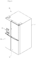
- Fig. 1 is a perspective view of a refrigerator according to an embodiment
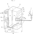
- Fig. 2 is a schematic view illustrating an arrangement of passages through which water of the refrigerator flows.
- a refrigerator 10 includes a main body 11 having a storage space with a front surface opened and a door for opening/closing the storage space.
- constitutions of the storage space may be different according to kinds and configurations of refrigerators.
- a freezing compartment 12 is disposed at a left side
- a refrigerating compartment 13 is disposed at a right side with respect to a barrier in Fig. 1
- the current embodiment is not limited to kinds of refrigerators, positions of the freezing compartment and refrigerating compartment, and the number of freezing compartment and refrigerating compartment.
- features described with reference to the accompanying drawings are not limited to the technical features of the present disclosure.
- the door may include a freezing compartment door 14 and a refrigerating compartment door 15. Also, upper and lower ends of the door may be rotatably connected to the main body 11 by hinges to open or close each of a refrigerating compartment 13 and a freezing compartment 12.
- a dispenser 20 may be disposed on a front surface of the freezing compartment door 14 or the refrigerating compartment door 15.
- Fig. 1 illustrates the dispenser 20 disposed in the freezing compartment door 14.
- the dispenser 20 may dispense water or ice cubes at the outside without opening the freezing compartment door 14.
- the dispenser 20 may have a shape that is recessed from a front surface of the freezing compartment door 14.
- An ice making device 27 is disposed on a back surface of the freezing compartment door 14.
- the ice making device 27 may freeze supplied water to make ice cubes, thereby storing the made ice cubes.
- the ice making device 27 may include an automatic ice maker 28 in which water is automatically supplied to make ice cubes and transfer the made ice cubes and an ice bank 29 disposed under the automatic ice maker 28 to store the ice cubes transferred from the automatic ice maker 28.
- the ice bank 29 may communicate with the dispenser 20 through an ice chute. Thus, when the dispenser 20 is manipulated, the ice cubes within the ice bank 29 may be dispensed through the dispenser 20 to the outside. Also, a constitution configured to dispense the stored ice cubes in a cubed ice state or crushed ice rubble state according to user's selection may be further provided in the ice bank 29.
- a filter device 40 for purifying water supplied from the external water supply source and a water tank 50 for storing the water purified by passing through the filter device 40 to cool the stored water by using cool air may be disposed in the main body 11.
- the filter device 40 will be described below in detail.
- the refrigerator 10 may be connected to an external water supply source 1. Also, a water supply flow path 60 connected to the water supply source 1, the filter device 40, the water tank 50, the dispenser 20, and the ice making device 27 to guide a flow of the water may be disposed in the main body 11 and the freezing compartment door 14.
- the water supply flow path 60 may include a water supply passage 61 connecting the water supply source 1 disposed outside the main body 11 such as a water pipe to the filter device 40 disposed in the main body 11, a purified water passage 62 for guiding the purified water into the dispenser 20, a cold water passage 63 for guiding the water purified by the filter device 40 into the dispenser 20 via the water tank 50, and an ice making passage 64 branched from the purified water passage 62 to guide the water purified by the filter device 40 into the ice making device 27.
- a water supply passage 61 connecting the water supply source 1 disposed outside the main body 11 such as a water pipe to the filter device 40 disposed in the main body 11, a purified water passage 62 for guiding the purified water into the dispenser 20, a cold water passage 63 for guiding the water purified by the filter device 40 into the dispenser 20 via the water tank 50, and an ice making passage 64 branched from the purified water passage 62 to guide the water purified by the filter device 40 into the ice making device
- the water supply flow path 60 may extend from the water supply source 1 to the inside of the main body 11 and then be connected to the filter device 40.
- the water supply passage 61 may be provided in two tubes with respect to the main body 11 and connected to a fitting member 611.
- the fitting member 611 may be disposed on a rear surface of the main body 11 so that a user selectively separates a tube of the water supply passage 61, which is connected to the water supply source 1.
- a water supply valve 612 may be disposed in the water supply passage 61.
- the water supply valve 612 may open or close the water supply passage 61 to adjust an amount of water supplied into the filter device 40.
- the water supply valve 612 may be disposed at one side of the main body 11. Also, if necessary, the water supply valve 612 may be integrated with the fitting member 611.
- the filter device 40 may be disposed in the refrigerating compartment 13.
- the water supply passage 61 may extend up to the inside of the refrigerating compartment 13.
- a cleaning passage 65 may be disposed in the filter device 40.
- the cleaning passage 65 may be connected to the water supply passage 61.
- the water of the water supply source 1 may be purified while passing through the filter device 40.
- the purified water passage 62 may connect the filter device 40 to the dispenser 20.
- the purified water passage 62 may extend from an outlet of the filter device 40 to one side of the dispenser 20 to supply the water purified in the filter device 40 into the dispenser 20.
- the purified water passage 62 may extend from the refrigerating compartment 13 in which the filter device 40 is disposed to the freezing compartment door 14 in which the dispenser 20 is disposed.
- the purified water passage 62 may pass through a hinge connecting the main body 11 to the freezing compartment door 14.
- a fitting member 621 may be disposed on the purified water passage 62 corresponding to the position of the hinge to connect the purified water passage 62 that is divided into two door-side and main body-side parts to each other.
- the connection and separation of the purified water passage 62 may be enabled according to the mounting and separation of the freezing compartment door 14.
- a purified water valve 622 may be disposed in the purified water passage 62.
- the purified water valve 622 may open or close the purified water passage 62 to selectively discharge the purified water into the dispenser 20.
- the purified water valve 622 may be, for example, a three-way valve that divides the water supplied from the purified water passage 62 to supply the divided water into the dispenser 20 and the ice making device 27.
- the purified water valve 622 may be disposed in the purified water passage 62 and be connected to the ice making passage 64 that is branched at the dispenser 20 or the freezing compartment door 14 to extend to the ice making device 27.
- the purified water passing through the filter device 40 may be directly dispensed into the dispenser 20 or supplied into the ice making device 27.
- the purified water supplied through the ice making passage 64 may have a relatively high temperature to prevent the water within the ice making passage 64 disposed in the refrigerating compartment door 14 from being frozen while flowing along the ice making passage 64, thereby stably supplying the water into the ice making device 27.
- the cold water passage 63 extends from the refrigerating compartment 13 to the freezing compartment door 14.
- the cold water passage 63 is configured to supply the water purified in the filter device 40 into the dispenser 20 after the water is cooled by passing through the water tank 50.
- the cold water passage 63 may be guided into the freezing compartment door 14 through the door hinge and be connected by the fitting member 631.
- the cold water passage 63 may be directly connected to the filter device 40. Alternatively, the cold water passage 63 may be branched at the purified water passage 62 and then connected to the water tank 50. Also, a cold water valve 632 may be disposed in the cold water passage 63 to selectively open or close the cold water passage 63 so that the cold water to be dispensed through the dispenser 20 is selectively discharged.
- the cold water valve 632 may be disposed in the cold water passage 63 between the water tank 50 and the dispenser 20.
- the cold water valve 632 may be opened or closed to determine the supply of water into the dispenser 20.
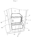
- Fig. 3 is a partial perspective view illustrating a portion of an inner space of the refrigerator
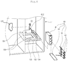
- Fig. 4 is a view illustrating mounted states of the water tank and the filter device according an embodiment.
- a plurality of receiving members 131 such as a drawer and shelf may be disposed in the refrigerating compartment 13.
- the receiving members 131 may partition the inside of the refrigerating compartment 13 to form receiving spaces having various shapes. Also, the receiving members 131 may be disposed adjacent to the filter device 40.
- a support member 132 may be disposed on one side of the refrigerating compartment 13.
- the support member 132 may support the receiving member 131 and the filter device 40 from lower sides of the receiving member 131 and the filter device 40.
- the support member 132 may be disposed on a bottom surface of the refrigerating compartment 13 or a top surface of the other receiving member.
- the support member 132 may have a plate shape that horizontally partitions the inside of the refrigerating compartment 13.
- a top surface of the support member 132 may be divided into two areas, i.e., a receiving member mounting part 133 for mounting the receiving members 131 and a filter device mounting part 134 for mounting the filter device 40. Also, a pair of insertion/withdrawal guides 135 for guiding slidable insertion or withdrawal of the receiving member 131 in a front/rear direction may be disposed on both left and right sides of the receiving member mounting part 133.
- the filter device 40 may be disposed on the filter device mounting part 134 and also be disposed between the receiving member 131 and an inner wall of the refrigerating compartment 13. Also, the filter device 40 may have front and top surfaces corresponding to those of the receiving member 131 so that the filter device 40 has a sense of unity with respect to the receiving member 131 inside the refrigerating compartment 13. Also, a shelf 136 may be mounted above the filter device 40 and the receiving member 131 to cover the receiving member 131 and the filter device 40 at the same time.
- the filter device 40 may comprise a housing 41 for incorporating one or several filters 42. The housing 41 may be placed on the support member 132. The housing 41 has openings for receiving the filters 42, and the openings may be covered by a front cover 44 of the housing 41.
- Rear surfaces of the receiving member 131 and the filter device 40 may be spaced apart from a rear wall of the refrigerating compartment 13.
- the water tank 50 may be disposed on the receiving member 131 and the filter device 40.
- the water purified in the filter device 40 may be stored in the water tank 50. Then, the water may be cooled by the cool air within the refrigerating compartment 13, and then the cold water may be supplied into the dispenser 20.
- the water tank 50 may have a size that is capable of being accommodated between the receiving member 131 and filter device 40 and the wall of the refrigerating compartment 13 and receive water therein.
- the water supply flow path 60 may be connected to the water tank 50, and the water tank 50 may be connected to the filter unit 40.
- a portion of the cold water passage 63 connected .to the dispenser 20 may be disposed in a space in which the water tank 50 is disposed.
- the cold water valve 632 may be fixedly mounted on the rear wall of the refrigerating compartment 13 above the water tank 50. Also, for safety, the cold valve 632 may be covered by a valve cover 137.
- the water tank 50, the cold water valve 632, and a portion of the water supply flow path 60 may be disposed in a space defined between the rear wall of the refrigerating compartment 13 in which the water tank 50 is disposed and the receiving member 131 and filter device 40.
- the receiving member 131 may have the same front/rear length as the filter device 40. Also, the front surface of the receiving member 131 and the front surface of the filter device 40 may be disposed on the same plane.
- Fig. 5 is a perspective of the filter device
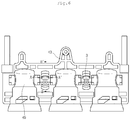
- Fig. 6 is a front view of a bracket and head
- Fig. 7 is a front view of a connector.
- the filter device 40 includes a bracket 43, at least two heads 45, and at least two filters 42.
- the present invention comprises two or more heads and filters.
- a connector 3 is connected between the heads 45.
- the head 45 are connected by the connector 3. Since the connector 3 is coupled to the bracket 43, the head 45 and the filter 42 may be fixed to the bracket 43. According to the above-described constitutions, the head 45 and the connector 3 are seated on the bracket 43 in the state where the head 45 and the connector 3 are connected to each other. Thereafter, the connector 3 rotates so that the connector 3 is fixed to a portion of the bracket 43.
- the connector 3 may rotate about a shaft connecting the heads 45 to each other. That is, the connector 3 may rotate about a central axis of a cylindrical body 31.
- a coupling force of the connector 3 and the bracket 43 may be transmitted into the head 45, and the head 45 and the filter 42 fixed to the head 45 may be firmly fixed and maintained in the fixed state.
- the water When water is supplied through one side of the bracket 43, the water may pass through the head 45 and then be introduced into the filter 42 coupled to the head 45. Thus, foreign substances within the water may be filtered. The water of which the foreign substances are filtered may be discharged again through the head and then be introduced into the next head through the connector. This process may be repeatedly performed. The water purified by passing through the three filters 42 may be drained through the other side of the bracket 43.
- the connector 3 may couple the bracket 43 to the head 45 and allow water to flow through an inner through-hole of the connector 3.
- the connector 3 may include an approximately cylindrical body 31 having an empty inner space through which water flows, a sealing protrusion 35 disposed on an outer circumference of the cylindrical body 31 to allow a contact part with the head 45 to be watertight, and a seating protrusion 32 for allowing the connector 3 to be seated on the bracket 43.
- a handle 33 may be disposed on a portion of the seating protrusion 32 to allow a user to grasp the handle 33 so that the user rotates the connector 3.
- An inner portion of the handle 33 may be provided as a coupling part 34.
- the coupling part 34 may be hooked with one side of the bracket 43 to couple the connector 3 and the bracket 43 to each other.
- the connector 3 may be formed of a resin material having predetermined strength to mechanically connect the heads 45 to each other.
- the connector 3 and the head 45 which are connected to each other, may move together with each other in a state where a structure of the connector 3 and the head 45 is maintained as a single assembly.
- the single assembly may be utilized in a following assembly process.
- a passage may be provided in the connector 3 to function as a passage connecting the heads 45 to each other.
- Fig. 8 is an enlarged front view illustrating a portion of the bracket on which the connector is placed.
- a head laying part 431 on which the head 45 is placed may be disposed on the bracket.
- the connector 3 may be seated on one side of the head laying part 431.
- a sealing guide 432 that is a portion on which the sealing protrusion 35 and a seating end 451 of the head 45 are seated while maintaining watertightness and a seating guide 433 on which the seating protrusion 32 is placed are provided on the portion on which the connector 3 is placed.
- An opening 435 that is opened to allow the handle 33 to rotate backward may be defined in a rear side of the seating guide 433.
- a coupling guide 434 may be disposed on the bracket 43 to guide the coupling part 34 when the connector 3 rotates backward. The coupling guide 434 may be opened forward so that the connector 3 is simply inserted.
- the watertightness of the connector 3 and the bracket 43 may be more accurately understood in Fig. 9 with reference to the cross-sectional view taken along line A-A' of Fig. 6 .
- a worker inserts the sealing protrusion 35 of the connector 3 into the seating end 451 of the head 45.
- a sealer 452 may be further inserted before the sealing protrusion 35 is inserted to prevent water from leaking between the head 45 and the connector 3.
- Each of the above-described parts may be formed of plastic. Thus, in case of reworking, damage of the parts may be prevented, and the water leakage may also be prevented.
- the above-described processes may be repeatedly performed to couple three heads 45 to two connectors 3.
- An assembly of the head 45 and the connector 3 may be seated on the bracket 43.
- the head 45 may be guided to the head seating part (see reference numeral 431 of Fig.
- the seating protrusion 32 of the connector 3 may be guided by the seating guide 433. Also, the portion at which the seating end 451 and the sealing protrusion 35 are assembled may be inserted in the state where the portion is guided by the sealing guide 432. The worker may easily seat the head 45 and the connector 3 through the above-described processes. Thus, work convenience may be improved.
- the sealing guide 432 has a width that is limited in a horizontal direction of Fig. 9 .
- the seating end 451 may be restricted in a state where the seating end 451 is pushed to a right side by a left end of the sealing guide 432, and the sealing protrusion 35 may be restricted in a state where the sealing protrusion 35 is pushed to a left side by a right end of the sealing guide 432.
- the sealer 452 may be disposed in a state where the sealer 452 is bidirectionally pressed, and a contact part between the head 45 and the connector 3 may be maintained in watertightness.
- An O-ring formed of an elastic material may be used as the sealer 452.
- the head 45 and the connector 3 are horizontally maintained by the above-described various parts without having a gap therebetween.
- the head 45 and the connector 3 may be in a state in which the head 45 and the connector 3 are not restricted inward and outward and thus be separated from the bracket 43. In this state, a gap may be provided so that the head 45 and the connector 3 may be vibrated.
- the head 45 and the connector 3 may not be completely fixed to each other.
- the handle 33 may rotate backward to completely couple the connector 3 to the bracket 43. Therefore, the worker may more easily assemble the filter device without performing a coupling process using a screw.
- Fig. 10 is a cross-sectional perspective view taken along line B-B' of Fig. 6 .
- the connector 3 may rotate about a central axis of the cylindrical body 31.
- the worker may rotate the handle 33 backward.
- the connector 3 since the seating protrusion 32 is guided by the seating guide 433, the connector 3 may not be horizontally vertically vibrated.
- the handle 33 may pass through the opening 435 to rotate backward. Then, when the handle 33 rotates at a predetermined angle or more, the handle 33 may be guided by the coupling guide 434. Since the handle 33 is hooked with the coupling guide 434, the connector 3 may not be separated forward. That is, even if it is intended to separate the connector 3 forward (i.e., a left side in the drawings), the handle 33 may be hooked with the coupling guide 434 to prevent the connector 3 from being separated forward.
- the handle 33 When the handle 33 continuously rotates, the handle 33 may reach the coupling protrusion 436. Here, the worker may further apply a force to the handle 33 so that the coupling part 34 of the handle 33 passes over the coupling protrusion 436. Thus, the coupling part 34 may pass over the coupling protrusion 436. As a result, the coupling process of the connector 3 and the bracket 43 may be finished. Here, the coupling part 34 may contact a stopper 439 and thus not rotates any more. Thus, even though external vibration or impact is applied, the handle may not reversely rotate and thus be firmly coupled at a predetermined angle.
- the interaction between the coupling part 34 and the coupling protrusion 436 may be understood with reference to the rear cutoff perspective view of the bracket 43 that is described in Fig. 11 .
- the connector may not move in all directions, i.e., front/rear, left/right, and upward/downward directions, but be fixed at an accurate position without having the gap.
- the head connected to the connector 3 may be stably placed at its proper seating position. Since the connector is fixed to the stable position without having the gap, the watertightness may be improved.
Description
- The present disclosure relates to a refrigerator and a filter device of the refrigerator.
- Refrigerators are home appliances for storing foods at a low temperature. Such a refrigerator includes one or all of a refrigerating compartment for storing foods in a refrigerated state and a freezing compartment for storing foods in a frozen state.
- In recent years, a dispenser may be mounted on a front surface of a door of the refrigerator. Thus, drinking water may be dispensed through the dispenser without opening the refrigerator door. Also, an ice maker for making ice cubes to store the made ice cubes may be disposed on the refrigerator door or in the storage compartment. Thus, the ice cubes may be dispensed through the dispenser. The drinking water may be supplied from an external water supply source. The supplied water may be supplied into the dispenser after passing through a filter device. Alternatively, the supplied water may be supplied into a water tank provided in the refrigerator, and the water stored in the water tank may be supplied into the dispenser and/or an ice maker after being cooled by cool air within the refrigerator so that the supply of water for dispensing drinking water to the outside or making an ice cube is enabled.
- .A plurality of filters which are aligned in the filter device, and the filter device is mounted at a predetermined position of the refrigerator. The filter device may be connected through a predetermined duct, and the duct may be fitted in a press-fit manner.
- European Patent Application No.
14 155 369.3 - United States Patent Application No.
10/948,081 - United States Patent Application No.
12/197,752 - However, when the filter device is connected through only the duct, the water may be leak, and a gap may be generated to cause a limitation in mounting. Therefore it is object of the present invention to create a refrigerator comprising a filter mount which cannot be accidentally dislodged but which can be easily replaced.
- Embodiments provide a refrigerator and a filter device of the refrigerator.
- The invention is defined in the
independent claim 1. - According to the present invention, a refrigerator includes: a main body to define a storage space; a door that opens and closes the storage space; a dispenser provided at the door to dispense water; at least two filters to purify water supplied from an external water supply source, thereby supplying the purified water into the dispenser; at least two heads to fix the at least two filters, respectively; a connector that connects the at least two heads to each other, the connector providing a passage between the at least two heads; and a bracket on which the connector and the at least two heads are seated, the bracket being coupled to the connector, in which the connector is in a state where the connector is connected to the at least two heads and comprises a handle with a coupling part; the bracket comprises a coupling protrusion for restricting free rotation of the coupling part of the connector in a rotation path of the connector, and a coupling guide that guides coupling of the coupling part and on which the coupling protrusion is disposed, when the handle rotates at a predetermined angle or more, the coupling part is hooked with the coupling protrusion.
- In one embodiment, the connector further comprises a cylindrical body having a passage therein; and the handle is extended from the cylindrical body.
- An opening for allowing the handle to rotate is defined in the bracket.
- The connector and the at least two heads are seated on the bracket in a state where the connector and the at least two heads are coupled to each other.
- The refrigerator may further comprise a seating protrusion disposed on an outer circumference of the connector; and a seating guide disposed on the bracket to restrict left and right movement of the connector by the seating protrusion disposed thereon.
- The refrigerator may further comprise a sealing protrusion disposed on an outer circumference of the connector; a seating end disposed on an end of the head; a sealing guide disposed on the bracket to restrict the sealing protrusion and the seating end.
- The details of one or more embodiments are set forth in the accompanying drawings and the description below. Other features will be apparent from the description and drawings, and from the claims.
-
-
Fig. 1 is a perspective view of a refrigerator according to an embodiment. -
Fig. 2 is a schematic view illustrating an arrangement of passages through which water of the refrigerator flows. -
Fig. 3 is a partial perspective view illustrating a portion of an inner space of the refrigerator. -
Fig. 4 is a view illustrating mounted states of a water tank and a filter device according an embodiment. -
Fig. 5 is a perspective of the filter device. -
Fig. 6 is a front view of a bracket and head. -
Fig. 7 is a front view of a connector. -
Fig. 8 is an enlarged front view illustrating a portion of the bracket on which the connector is placed. -
Fig. 9 is a cross-sectional view taken along line A-A' ofFig. 6 . -
Fig. 10 is a cross-sectional perspective view taken along line B-B' ofFig. 6 . -
Fig. 11 is a rear cutoff perspective view of the bracket. - Reference will now be made in detail to the embodiments of the present disclosure, examples of which are illustrated in the accompanying drawings.
- In the following detailed description of the preferred embodiments, reference is made to the accompanying drawings that form a part hereof, and in which is shown by way of illustration specific preferred embodiments in which the invention may be practiced. These embodiments are described in sufficient detail to enable those skilled in the art to practice the invention, and it is understood that other embodiments may be utilized and that logical structural, mechanical, electrical, and chemical changes may be made without departing from the scope of the invention. To avoid detail not necessary to enable those skilled in the art to practice the invention, the description may omit certain information known to those skilled in the art. The following detailed description is, therefore, not to be taken in a limiting sense.
- Also, in the description of embodiments, terms such as first, second, A, B, (a), (b) or the like may be used herein when describing components of the present invention. Each of these terminologies is not used to define an essence, order or sequence of a corresponding component but used merely to distinguish the corresponding component from other component (s) . It should be noted that if it is described in the specification that one component is "connected," "coupled" or "joined" to another component, the former may be directly "connected," "coupled," and "joined" to the latter or "connected", "coupled", and "joined" to the latter via another component.
- A refrigerator according to an embodiment is capable of being applied to all types of refrigerators each of which is connected to an external water supply source to supply water into a dispenser and includes a filter and water tank therein.
-
Fig. 1 is a perspective view of a refrigerator according to an embodiment, andFig. 2 is a schematic view illustrating an arrangement of passages through which water of the refrigerator flows. - Referring to
Figs. 1 and2 , arefrigerator 10 according to the current embodiment includes amain body 11 having a storage space with a front surface opened and a door for opening/closing the storage space. - Here, constitutions of the storage space may be different according to kinds and configurations of refrigerators. For example, although a
freezing compartment 12 is disposed at a left side, and a refrigeratingcompartment 13 is disposed at a right side with respect to a barrier inFig. 1 , the current embodiment is not limited to kinds of refrigerators, positions of the freezing compartment and refrigerating compartment, and the number of freezing compartment and refrigerating compartment. Also, features described with reference to the accompanying drawings are not limited to the technical features of the present disclosure. - The door may include a
freezing compartment door 14 and a refrigeratingcompartment door 15. Also, upper and lower ends of the door may be rotatably connected to themain body 11 by hinges to open or close each of a refrigeratingcompartment 13 and afreezing compartment 12. - A
dispenser 20 may be disposed on a front surface of thefreezing compartment door 14 or the refrigeratingcompartment door 15. For example,Fig. 1 illustrates thedispenser 20 disposed in thefreezing compartment door 14. Thedispenser 20 may dispense water or ice cubes at the outside without opening thefreezing compartment door 14. Thedispenser 20 may have a shape that is recessed from a front surface of thefreezing compartment door 14. - An ice making device 27 is disposed on a back surface of the
freezing compartment door 14. The ice making device 27 may freeze supplied water to make ice cubes, thereby storing the made ice cubes. Particularly, the ice making device 27 may include anautomatic ice maker 28 in which water is automatically supplied to make ice cubes and transfer the made ice cubes and an ice bank 29 disposed under theautomatic ice maker 28 to store the ice cubes transferred from theautomatic ice maker 28. - The ice bank 29 may communicate with the
dispenser 20 through an ice chute. Thus, when thedispenser 20 is manipulated, the ice cubes within the ice bank 29 may be dispensed through thedispenser 20 to the outside. Also, a constitution configured to dispense the stored ice cubes in a cubed ice state or crushed ice rubble state according to user's selection may be further provided in the ice bank 29. - A
filter device 40 for purifying water supplied from the external water supply source and awater tank 50 for storing the water purified by passing through thefilter device 40 to cool the stored water by using cool air may be disposed in themain body 11. - The
filter device 40 will be described below in detail. - To supply water into the
dispenser 20 and the ice making device 27, therefrigerator 10 may be connected to an externalwater supply source 1. Also, a watersupply flow path 60 connected to thewater supply source 1, thefilter device 40, thewater tank 50, thedispenser 20, and the ice making device 27 to guide a flow of the water may be disposed in themain body 11 and the freezingcompartment door 14. - The water
supply flow path 60 may include awater supply passage 61 connecting thewater supply source 1 disposed outside themain body 11 such as a water pipe to thefilter device 40 disposed in themain body 11, apurified water passage 62 for guiding the purified water into thedispenser 20, acold water passage 63 for guiding the water purified by thefilter device 40 into thedispenser 20 via thewater tank 50, and anice making passage 64 branched from the purifiedwater passage 62 to guide the water purified by thefilter device 40 into the ice making device 27. - The water
supply flow path 60 may extend from thewater supply source 1 to the inside of themain body 11 and then be connected to thefilter device 40. Here, thewater supply passage 61 may be provided in two tubes with respect to themain body 11 and connected to afitting member 611. Here, thefitting member 611 may be disposed on a rear surface of themain body 11 so that a user selectively separates a tube of thewater supply passage 61, which is connected to thewater supply source 1. - A
water supply valve 612 may be disposed in thewater supply passage 61. Thewater supply valve 612 may open or close thewater supply passage 61 to adjust an amount of water supplied into thefilter device 40. Thewater supply valve 612 may be disposed at one side of themain body 11. Also, if necessary, thewater supply valve 612 may be integrated with thefitting member 611. - The
filter device 40 may be disposed in therefrigerating compartment 13. In this case, thewater supply passage 61 may extend up to the inside of therefrigerating compartment 13. Acleaning passage 65 may be disposed in thefilter device 40. Thecleaning passage 65 may be connected to thewater supply passage 61. Thus, the water of thewater supply source 1 may be purified while passing through thefilter device 40. - The
purified water passage 62 may connect thefilter device 40 to thedispenser 20. Thepurified water passage 62 may extend from an outlet of thefilter device 40 to one side of thedispenser 20 to supply the water purified in thefilter device 40 into thedispenser 20. - The
purified water passage 62 may extend from the refrigeratingcompartment 13 in which thefilter device 40 is disposed to the freezingcompartment door 14 in which thedispenser 20 is disposed. Thepurified water passage 62 may pass through a hinge connecting themain body 11 to the freezingcompartment door 14. Here, afitting member 621 may be disposed on the purifiedwater passage 62 corresponding to the position of the hinge to connect the purifiedwater passage 62 that is divided into two door-side and main body-side parts to each other. Thus, the connection and separation of the purifiedwater passage 62 may be enabled according to the mounting and separation of the freezingcompartment door 14. - A
purified water valve 622 may be disposed in the purifiedwater passage 62. The purifiedwater valve 622 may open or close the purifiedwater passage 62 to selectively discharge the purified water into thedispenser 20. The purifiedwater valve 622 may be, for example, a three-way valve that divides the water supplied from the purifiedwater passage 62 to supply the divided water into thedispenser 20 and the ice making device 27. - That is, the purified
water valve 622 may be disposed in the purifiedwater passage 62 and be connected to theice making passage 64 that is branched at thedispenser 20 or the freezingcompartment door 14 to extend to the ice making device 27. Thus, the purified water passing through thefilter device 40 may be directly dispensed into thedispenser 20 or supplied into the ice making device 27. Also, the purified water supplied through theice making passage 64 may have a relatively high temperature to prevent the water within theice making passage 64 disposed in therefrigerating compartment door 14 from being frozen while flowing along theice making passage 64, thereby stably supplying the water into the ice making device 27. - The
cold water passage 63 extends from the refrigeratingcompartment 13 to the freezingcompartment door 14. Thecold water passage 63 is configured to supply the water purified in thefilter device 40 into thedispenser 20 after the water is cooled by passing through thewater tank 50. - Here, the
cold water passage 63 may be guided into the freezingcompartment door 14 through the door hinge and be connected by thefitting member 631. - The
cold water passage 63 may be directly connected to thefilter device 40. Alternatively, thecold water passage 63 may be branched at thepurified water passage 62 and then connected to thewater tank 50. Also, acold water valve 632 may be disposed in thecold water passage 63 to selectively open or close thecold water passage 63 so that the cold water to be dispensed through thedispenser 20 is selectively discharged. - The
cold water valve 632 may be disposed in thecold water passage 63 between thewater tank 50 and thedispenser 20. Thecold water valve 632 may be opened or closed to determine the supply of water into thedispenser 20. -
Fig. 3 is a partial perspective view illustrating a portion of an inner space of the refrigerator, andFig. 4 is a view illustrating mounted states of the water tank and the filter device according an embodiment. - Referring to
Figs. 3 and4 , a plurality of receivingmembers 131 such as a drawer and shelf may be disposed in therefrigerating compartment 13. The receivingmembers 131 may partition the inside of therefrigerating compartment 13 to form receiving spaces having various shapes. Also, the receivingmembers 131 may be disposed adjacent to thefilter device 40. - A
support member 132 may be disposed on one side of therefrigerating compartment 13. Thesupport member 132 may support the receivingmember 131 and thefilter device 40 from lower sides of the receivingmember 131 and thefilter device 40. Also, thesupport member 132 may be disposed on a bottom surface of therefrigerating compartment 13 or a top surface of the other receiving member. Also, thesupport member 132 may have a plate shape that horizontally partitions the inside of therefrigerating compartment 13. - A top surface of the
support member 132 may be divided into two areas, i.e., a receivingmember mounting part 133 for mounting the receivingmembers 131 and a filterdevice mounting part 134 for mounting thefilter device 40. Also, a pair of insertion/withdrawal guides 135 for guiding slidable insertion or withdrawal of the receivingmember 131 in a front/rear direction may be disposed on both left and right sides of the receivingmember mounting part 133. - Also, the
filter device 40 may be disposed on the filterdevice mounting part 134 and also be disposed between the receivingmember 131 and an inner wall of therefrigerating compartment 13. Also, thefilter device 40 may have front and top surfaces corresponding to those of the receivingmember 131 so that thefilter device 40 has a sense of unity with respect to the receivingmember 131 inside the refrigeratingcompartment 13. Also, ashelf 136 may be mounted above thefilter device 40 and the receivingmember 131 to cover the receivingmember 131 and thefilter device 40 at the same time. Thefilter device 40 may comprise ahousing 41 for incorporating one orseveral filters 42. Thehousing 41 may be placed on thesupport member 132. Thehousing 41 has openings for receiving thefilters 42, and the openings may be covered by afront cover 44 of thehousing 41. - Rear surfaces of the receiving
member 131 and thefilter device 40 may be spaced apart from a rear wall of therefrigerating compartment 13. Thewater tank 50 may be disposed on the receivingmember 131 and thefilter device 40. The water purified in thefilter device 40 may be stored in thewater tank 50. Then, the water may be cooled by the cool air within therefrigerating compartment 13, and then the cold water may be supplied into thedispenser 20. - The
water tank 50 may have a size that is capable of being accommodated between the receivingmember 131 andfilter device 40 and the wall of therefrigerating compartment 13 and receive water therein. Also, the watersupply flow path 60 may be connected to thewater tank 50, and thewater tank 50 may be connected to thefilter unit 40. Also, a portion of thecold water passage 63 connected .to thedispenser 20 may be disposed in a space in which thewater tank 50 is disposed. Also, thecold water valve 632 may be fixedly mounted on the rear wall of therefrigerating compartment 13 above thewater tank 50. Also, for safety, thecold valve 632 may be covered by avalve cover 137. As described above, thewater tank 50, thecold water valve 632, and a portion of the watersupply flow path 60 may be disposed in a space defined between the rear wall of therefrigerating compartment 13 in which thewater tank 50 is disposed and the receivingmember 131 andfilter device 40. - The receiving
member 131 may have the same front/rear length as thefilter device 40. Also, the front surface of the receivingmember 131 and the front surface of thefilter device 40 may be disposed on the same plane. -
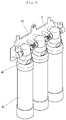
Fig. 5 is a perspective of the filter device,Fig. 6 is a front view of a bracket and head, andFig. 7 is a front view of a connector. - Referring to
Figs. 5 to 7 , thefilter device 40 according to the present invention includes abracket 43, at least twoheads 45, and at least twofilters 42. For example, although threeheads 45 are fixed to thebracket 43, and threefilters 42 are respectively fixed to theheads 45, the present invention comprises two or more heads and filters. Aconnector 3 is connected between theheads 45. Thehead 45 are connected by theconnector 3. Since theconnector 3 is coupled to thebracket 43, thehead 45 and thefilter 42 may be fixed to thebracket 43. According to the above-described constitutions, thehead 45 and theconnector 3 are seated on thebracket 43 in the state where thehead 45 and theconnector 3 are connected to each other. Thereafter, theconnector 3 rotates so that theconnector 3 is fixed to a portion of thebracket 43. Here, theconnector 3 may rotate about a shaft connecting theheads 45 to each other. That is, theconnector 3 may rotate about a central axis of acylindrical body 31. Thus, a coupling force of theconnector 3 and thebracket 43 may be transmitted into thehead 45, and thehead 45 and thefilter 42 fixed to thehead 45 may be firmly fixed and maintained in the fixed state. - When water is supplied through one side of the
bracket 43, the water may pass through thehead 45 and then be introduced into thefilter 42 coupled to thehead 45. Thus, foreign substances within the water may be filtered. The water of which the foreign substances are filtered may be discharged again through the head and then be introduced into the next head through the connector. This process may be repeatedly performed. The water purified by passing through the threefilters 42 may be drained through the other side of thebracket 43. Theconnector 3 may couple thebracket 43 to thehead 45 and allow water to flow through an inner through-hole of theconnector 3. - Referring to
Fig. 7 , theconnector 3 may include an approximatelycylindrical body 31 having an empty inner space through which water flows, a sealingprotrusion 35 disposed on an outer circumference of thecylindrical body 31 to allow a contact part with thehead 45 to be watertight, and aseating protrusion 32 for allowing theconnector 3 to be seated on thebracket 43. - A
handle 33 may be disposed on a portion of theseating protrusion 32 to allow a user to grasp thehandle 33 so that the user rotates theconnector 3. An inner portion of thehandle 33 may be provided as acoupling part 34. Thus, thecoupling part 34 may be hooked with one side of thebracket 43 to couple theconnector 3 and thebracket 43 to each other. - The
connector 3 may be formed of a resin material having predetermined strength to mechanically connect theheads 45 to each other. Thus, theconnector 3 and thehead 45, which are connected to each other, may move together with each other in a state where a structure of theconnector 3 and thehead 45 is maintained as a single assembly. Also, the single assembly may be utilized in a following assembly process. A passage may be provided in theconnector 3 to function as a passage connecting theheads 45 to each other. -
Fig. 8 is an enlarged front view illustrating a portion of the bracket on which the connector is placed. - Referring to
Fig. 8 , ahead laying part 431 on which thehead 45 is placed may be disposed on the bracket. Theconnector 3 may be seated on one side of thehead laying part 431. A sealingguide 432 that is a portion on which the sealingprotrusion 35 and aseating end 451 of thehead 45 are seated while maintaining watertightness and aseating guide 433 on which theseating protrusion 32 is placed are provided on the portion on which theconnector 3 is placed. Anopening 435 that is opened to allow thehandle 33 to rotate backward may be defined in a rear side of theseating guide 433. Acoupling guide 434 may be disposed on thebracket 43 to guide thecoupling part 34 when theconnector 3 rotates backward. Thecoupling guide 434 may be opened forward so that theconnector 3 is simply inserted. - The watertightness of the
connector 3 and thebracket 43 may be more accurately understood inFig. 9 with reference to the cross-sectional view taken along line A-A' ofFig. 6 . - Referring to
Fig. 9 , a worker inserts the sealingprotrusion 35 of theconnector 3 into theseating end 451 of thehead 45. Here, asealer 452 may be further inserted before the sealingprotrusion 35 is inserted to prevent water from leaking between thehead 45 and theconnector 3. Each of the above-described parts may be formed of plastic. Thus, in case of reworking, damage of the parts may be prevented, and the water leakage may also be prevented. The above-described processes may be repeatedly performed to couple threeheads 45 to twoconnectors 3. An assembly of thehead 45 and theconnector 3 may be seated on thebracket 43. Here, thehead 45 may be guided to the head seating part (seereference numeral 431 ofFig. 8 ), and theseating protrusion 32 of theconnector 3 may be guided by theseating guide 433. Also, the portion at which theseating end 451 and the sealingprotrusion 35 are assembled may be inserted in the state where the portion is guided by the sealingguide 432. The worker may easily seat thehead 45 and theconnector 3 through the above-described processes. Thus, work convenience may be improved. - The sealing
guide 432 has a width that is limited in a horizontal direction ofFig. 9 . Thus, theseating end 451 may be restricted in a state where theseating end 451 is pushed to a right side by a left end of the sealingguide 432, and the sealingprotrusion 35 may be restricted in a state where the sealingprotrusion 35 is pushed to a left side by a right end of the sealingguide 432. Thus, thesealer 452 may be disposed in a state where thesealer 452 is bidirectionally pressed, and a contact part between thehead 45 and theconnector 3 may be maintained in watertightness. An O-ring formed of an elastic material may be used as thesealer 452. - As understood in
Fig. 9 , it is seen that thehead 45 and theconnector 3 are horizontally maintained by the above-described various parts without having a gap therebetween. However, thehead 45 and theconnector 3 may be in a state in which thehead 45 and theconnector 3 are not restricted inward and outward and thus be separated from thebracket 43. In this state, a gap may be provided so that thehead 45 and theconnector 3 may be vibrated. Thus, thehead 45 and theconnector 3 may not be completely fixed to each other. As a result, thehandle 33 may rotate backward to completely couple theconnector 3 to thebracket 43. Therefore, the worker may more easily assemble the filter device without performing a coupling process using a screw. -
Fig. 10 is a cross-sectional perspective view taken along line B-B' ofFig. 6 . - Referring to
Fig. 10 , in the state where theconnector 3 is placed on thebracket 43, theconnector 3 may rotate about a central axis of thecylindrical body 31. Thus, the worker may rotate thehandle 33 backward. Of cause, since theseating protrusion 32 is guided by theseating guide 433, theconnector 3 may not be horizontally vertically vibrated. - The
handle 33 may pass through theopening 435 to rotate backward. Then, when thehandle 33 rotates at a predetermined angle or more, thehandle 33 may be guided by thecoupling guide 434. Since thehandle 33 is hooked with thecoupling guide 434, theconnector 3 may not be separated forward. That is, even if it is intended to separate theconnector 3 forward (i.e., a left side in the drawings), thehandle 33 may be hooked with thecoupling guide 434 to prevent theconnector 3 from being separated forward. - When the
handle 33 continuously rotates, thehandle 33 may reach thecoupling protrusion 436. Here, the worker may further apply a force to thehandle 33 so that thecoupling part 34 of thehandle 33 passes over thecoupling protrusion 436. Thus, thecoupling part 34 may pass over thecoupling protrusion 436. As a result, the coupling process of theconnector 3 and thebracket 43 may be finished. Here, thecoupling part 34 may contact astopper 439 and thus not rotates any more. Thus, even though external vibration or impact is applied, the handle may not reversely rotate and thus be firmly coupled at a predetermined angle. The interaction between thecoupling part 34 and thecoupling protrusion 436 may be understood with reference to the rear cutoff perspective view of thebracket 43 that is described inFig. 11 . - When the coupling process is finished through the above-described processes, the connector may not move in all directions, i.e., front/rear, left/right, and upward/downward directions, but be fixed at an accurate position without having the gap. In addition, the head connected to the
connector 3 may be stably placed at its proper seating position. Since the connector is fixed to the stable position without having the gap, the watertightness may be improved. - Although embodiments have been described with reference to a number of illustrative embodiments thereof, it should be understood that numerous other modifications and embodiments can be devised by those skilled in the art that will fall within the scope of the principles of this disclosure. More particularly, various variations and modifications are possible in the component parts and/or arrangements of the subject combination arrangement within the scope of the disclosure, the drawings and the appended claims. In addition to variations and modifications in the component parts and/or arrangements, alternative uses will also be apparent to those skilled in the art.
Claims (6)
- A refrigerator (10) comprising:a main body (11) to define a storage space (12);a door (14) that opens and closes the storage space (12);a dispenser (20) provided at the door (14) to dispense water;at least two filters (42) to purify water supplied from an external water supply source (1), thereby supplying the purified water into the dispenser (20);at least two heads (45) to fix the at least two filters (42), respectively;a connector (3) that connects the at least two heads (45) to each other, the connector (3) providing a passage between the at least two heads (45); anda bracket (43) on which the connector (3) and the at least two heads (45) are seated, the bracket (43) being coupled to the connector (3),characterized in that the connector (3) is rotatable in a state where the connector (3) is connected to the at least two heads (45) and comprises a handle (33) with a coupling part (34),the bracket (43) comprises a coupling protrusion (436) for restricting free rotation of a coupling part (34) of the connector (3) in a rotation path of the connector (3), and a coupling guide (434) that guides coupling of the coupling part (34) and on which the coupling protrusion (436) is disposed and wherein the coupling part (34) may pass over the coupling protrusion (436) whereby the connector (3) and the bracket (43) are coupled such that the handle may not reversely rotate and thus be firmly coupled at a predetermined angle.
- The refrigerator according to claim 1, wherein the connector (3) further comprises a cylindrical body (31) having a passage therein; and the handle (33) is extended from the cylindrical body (31).
- The refrigerator according to claim 1, wherein an opening (435) for allowing the handle (33) to rotate is defined in the bracket (43).
- The refrigerator according to any one of the claims 1 to 3, wherein the connector (3) and the at least two heads (45) are seated on the bracket (43) in a state where the connector (3) and the at least two heads (45) are coupled to each other.
- The refrigerator according to any one of the claims 1 to 4, further comprising:a seating protrusion (32) disposed on an outer circumference of the connector (3); anda seating guide (433) disposed on the bracket (43) to restrict left and right movement of the connector (3) by the seating protrusion (32) disposed thereon.
- The refrigerator according to any one of the claims 1 to 5, further comprising:a sealing protrusion (35) disposed on an outer circumference of the connector (3);a seating end (451) disposed on an end of the head (45); anda sealing guide (432) disposed on the bracket (43) to restrict the sealing protrusion (35) and the seating end (451).
Priority Applications (1)
| Application Number | Priority Date | Filing Date | Title |
|---|---|---|---|
| EP19178655.7A EP3553431B1 (en) | 2014-02-12 | 2014-12-12 | Refrigerator |
Applications Claiming Priority (1)
| Application Number | Priority Date | Filing Date | Title |
|---|---|---|---|
| KR1020140015797A KR101601391B1 (en) | 2014-02-12 | 2014-02-12 | Refrigerator and water purification apparatus for the refrigerator |
Related Child Applications (1)
| Application Number | Title | Priority Date | Filing Date |
|---|---|---|---|
| EP19178655.7A Division EP3553431B1 (en) | 2014-02-12 | 2014-12-12 | Refrigerator |
Publications (2)
| Publication Number | Publication Date |
|---|---|
| EP2908075A1 EP2908075A1 (en) | 2015-08-19 |
| EP2908075B1 true EP2908075B1 (en) | 2019-06-12 |
Family
ID=52016504
Family Applications (2)
| Application Number | Title | Priority Date | Filing Date |
|---|---|---|---|
| EP19178655.7A Active EP3553431B1 (en) | 2014-02-12 | 2014-12-12 | Refrigerator |
| EP14197543.3A Active EP2908075B1 (en) | 2014-02-12 | 2014-12-12 | Refrigerator |
Family Applications Before (1)
| Application Number | Title | Priority Date | Filing Date |
|---|---|---|---|
| EP19178655.7A Active EP3553431B1 (en) | 2014-02-12 | 2014-12-12 | Refrigerator |
Country Status (4)
| Country | Link |
|---|---|
| US (1) | US9835371B2 (en) |
| EP (2) | EP3553431B1 (en) |
| KR (1) | KR101601391B1 (en) |
| CN (1) | CN104833158B (en) |
Cited By (2)
| Publication number | Priority date | Publication date | Assignee | Title |
|---|---|---|---|---|
| US10697694B2 (en) | 2016-08-23 | 2020-06-30 | Dometic Sweden Ab | Cabinet for a recreational vehicle |
| US11187456B2 (en) | 2016-08-26 | 2021-11-30 | Dometic Sweden Ab | Refrigerating device for a recreational vehicle |
Families Citing this family (9)
| Publication number | Priority date | Publication date | Assignee | Title |
|---|---|---|---|---|
| KR101788965B1 (en) | 2016-03-22 | 2017-10-20 | 엘지전자 주식회사 | water purifing apparatus refrigerator |
| KR101760210B1 (en) * | 2016-03-29 | 2017-07-20 | 엘지전자 주식회사 | water purifing apparatus refrigerator |
| US10252198B2 (en) * | 2017-03-02 | 2019-04-09 | Bsh Hausgeraete Gmbh | Filter device for a beverage and/or ice dispenser unit of a household cooling appliance and household appliance having a filter device |
| KR101897922B1 (en) * | 2017-09-12 | 2018-09-12 | 엘지전자 주식회사 | Filter structure |
| KR102620165B1 (en) * | 2017-10-24 | 2024-01-04 | 주식회사 피코그램 | a water purifier having connector with optimization fluid |
| USD987772S1 (en) | 2020-07-02 | 2023-05-30 | Qingdao Ecopure Filter Co., Ltd. | Water filter |
| US11872510B2 (en) | 2021-07-01 | 2024-01-16 | Qingdao Ecopure Filter Co., Ltd | Water filter |
| USD1019884S1 (en) | 2021-08-03 | 2024-03-26 | Qingdao Ecopure Filter Co., Ltd. | Water filter |
| USD1016970S1 (en) | 2021-09-03 | 2024-03-05 | Qingdao Ecopure Filter Co., Ltd | Water filter |
Family Cites Families (14)
| Publication number | Priority date | Publication date | Assignee | Title |
|---|---|---|---|---|
| ITPD20010179A1 (en) * | 2001-07-17 | 2003-01-17 | Askoll Holding Srl | PIPE FITTING GROUP WITH SAFETY LOCK FOR EXTERNAL FILTERS FOR AQUARIUMS. |
| EP1423180B1 (en) * | 2001-07-31 | 2006-11-22 | 3M Innovative Properties Company | Water filter assembly for use in an appliance |
| US6740235B2 (en) * | 2002-03-04 | 2004-05-25 | Culligan International Company | Swivelling filter head assembly |
| WO2005030658A1 (en) | 2003-09-23 | 2005-04-07 | 3M Innovative Properties Company | Reduced pressure water filtration system |
| WO2005073124A2 (en) * | 2004-01-20 | 2005-08-11 | 3M Innovative Properties Company | Water dispenser with water filter for a refrigerator |
| DE102006049084A1 (en) | 2006-10-13 | 2008-04-17 | Bwt Ag | Water purification cartridge |
| EP2192364B1 (en) | 2007-11-05 | 2018-10-31 | Lg Electronics Inc. | Refrigerator |
| TW200948451A (en) * | 2008-05-20 | 2009-12-01 | Zhi-Hao Cai | Water treatment device featuring easy replacement of filter |
| KR101669662B1 (en) | 2009-01-07 | 2016-10-28 | 삼성전자주식회사 | Water filter device and refrigerator having the same |
| US9115920B2 (en) | 2009-01-07 | 2015-08-25 | Samsung Electronics Co., Ltd. | Water filter device and refrigerator having the same |
| KR101134140B1 (en) * | 2009-11-16 | 2012-04-09 | 서경아 | Apparatus for supporting filter and filter assembly using there of |
| KR101069736B1 (en) | 2010-02-02 | 2011-10-05 | 임동원 | Adapter Structure of Filter for Water Ionizer |
| US9157677B2 (en) * | 2010-08-17 | 2015-10-13 | General Electric Company | Refrigerator water filter assembly |
| EP2770280B1 (en) | 2013-02-20 | 2016-09-07 | LG Electronics Inc. | Refrigerator |
-
2014
- 2014-02-12 KR KR1020140015797A patent/KR101601391B1/en active IP Right Grant
- 2014-12-12 EP EP19178655.7A patent/EP3553431B1/en active Active
- 2014-12-12 EP EP14197543.3A patent/EP2908075B1/en active Active
-
2015
- 2015-01-13 US US14/595,347 patent/US9835371B2/en active Active
- 2015-01-21 CN CN201510029474.3A patent/CN104833158B/en active Active
Non-Patent Citations (1)
| Title |
|---|
| None * |
Cited By (3)
| Publication number | Priority date | Publication date | Assignee | Title |
|---|---|---|---|---|
| US10697694B2 (en) | 2016-08-23 | 2020-06-30 | Dometic Sweden Ab | Cabinet for a recreational vehicle |
| US11187456B2 (en) | 2016-08-26 | 2021-11-30 | Dometic Sweden Ab | Refrigerating device for a recreational vehicle |
| US11578913B2 (en) | 2016-08-26 | 2023-02-14 | Dometic Sweden Ab | Refrigerating device for a recreational vehicle |
Also Published As
| Publication number | Publication date |
|---|---|
| KR101601391B1 (en) | 2016-03-08 |
| KR20150094904A (en) | 2015-08-20 |
| CN104833158B (en) | 2017-05-03 |
| US20150226473A1 (en) | 2015-08-13 |
| CN104833158A (en) | 2015-08-12 |
| US9835371B2 (en) | 2017-12-05 |
| EP3553431A1 (en) | 2019-10-16 |
| EP2908075A1 (en) | 2015-08-19 |
| EP3553431B1 (en) | 2021-02-24 |
Similar Documents
| Publication | Publication Date | Title |
|---|---|---|
| EP2908075B1 (en) | Refrigerator | |
| US11326832B2 (en) | Refrigerator | |
| EP2905564B1 (en) | Refrigerator | |
| US10905987B2 (en) | Water purifying apparatus and filter structure | |
| US10584908B2 (en) | Refrigerator | |
| EP3406992B1 (en) | Refrigerator | |
| US20120297814A1 (en) | Refrigerator and water tank assembly for refrigerator | |
| KR20110072369A (en) | Refrigerator | |
| KR101758922B1 (en) | Refrigerator |
Legal Events
| Date | Code | Title | Description |
|---|---|---|---|
| PUAI | Public reference made under article 153(3) epc to a published international application that has entered the european phase |
Free format text: ORIGINAL CODE: 0009012 |
|
| AK | Designated contracting states |
Kind code of ref document: A1 Designated state(s): AL AT BE BG CH CY CZ DE DK EE ES FI FR GB GR HR HU IE IS IT LI LT LU LV MC MK MT NL NO PL PT RO RS SE SI SK SM TR |
|
| AX | Request for extension of the european patent |
Extension state: BA ME |
|
| 17P | Request for examination filed |
Effective date: 20150901 |
|
| RBV | Designated contracting states (corrected) |
Designated state(s): AL AT BE BG CH CY CZ DE DK EE ES FI FR GB GR HR HU IE IS IT LI LT LU LV MC MK MT NL NO PL PT RO RS SE SI SK SM TR |
|
| GRAP | Despatch of communication of intention to grant a patent |
Free format text: ORIGINAL CODE: EPIDOSNIGR1 |
|
| STAA | Information on the status of an ep patent application or granted ep patent |
Free format text: STATUS: GRANT OF PATENT IS INTENDED |
|
| INTG | Intention to grant announced |
Effective date: 20181219 |
|
| RAP1 | Party data changed (applicant data changed or rights of an application transferred) |
Owner name: LG ELECTRONICS INC. |
|
| GRAS | Grant fee paid |
Free format text: ORIGINAL CODE: EPIDOSNIGR3 |
|
| GRAA | (expected) grant |
Free format text: ORIGINAL CODE: 0009210 |
|
| STAA | Information on the status of an ep patent application or granted ep patent |
Free format text: STATUS: THE PATENT HAS BEEN GRANTED |
|
| AK | Designated contracting states |
Kind code of ref document: B1 Designated state(s): AL AT BE BG CH CY CZ DE DK EE ES FI FR GB GR HR HU IE IS IT LI LT LU LV MC MK MT NL NO PL PT RO RS SE SI SK SM TR |
|
| REG | Reference to a national code |
Ref country code: GB Ref legal event code: FG4D |
|
| REG | Reference to a national code |
Ref country code: CH Ref legal event code: EP |
|
| REG | Reference to a national code |
Ref country code: AT Ref legal event code: REF Ref document number: 1143094 Country of ref document: AT Kind code of ref document: T Effective date: 20190615 |
|
| REG | Reference to a national code |
Ref country code: DE Ref legal event code: R096 Ref document number: 602014048117 Country of ref document: DE |
|
| REG | Reference to a national code |
Ref country code: IE Ref legal event code: FG4D |
|
| REG | Reference to a national code |
Ref country code: NL Ref legal event code: MP Effective date: 20190612 |
|
| REG | Reference to a national code |
Ref country code: LT Ref legal event code: MG4D |
|
| PG25 | Lapsed in a contracting state [announced via postgrant information from national office to epo] |
Ref country code: SE Free format text: LAPSE BECAUSE OF FAILURE TO SUBMIT A TRANSLATION OF THE DESCRIPTION OR TO PAY THE FEE WITHIN THE PRESCRIBED TIME-LIMIT Effective date: 20190612 Ref country code: HR Free format text: LAPSE BECAUSE OF FAILURE TO SUBMIT A TRANSLATION OF THE DESCRIPTION OR TO PAY THE FEE WITHIN THE PRESCRIBED TIME-LIMIT Effective date: 20190612 Ref country code: LT Free format text: LAPSE BECAUSE OF FAILURE TO SUBMIT A TRANSLATION OF THE DESCRIPTION OR TO PAY THE FEE WITHIN THE PRESCRIBED TIME-LIMIT Effective date: 20190612 Ref country code: AL Free format text: LAPSE BECAUSE OF FAILURE TO SUBMIT A TRANSLATION OF THE DESCRIPTION OR TO PAY THE FEE WITHIN THE PRESCRIBED TIME-LIMIT Effective date: 20190612 Ref country code: FI Free format text: LAPSE BECAUSE OF FAILURE TO SUBMIT A TRANSLATION OF THE DESCRIPTION OR TO PAY THE FEE WITHIN THE PRESCRIBED TIME-LIMIT Effective date: 20190612 Ref country code: NO Free format text: LAPSE BECAUSE OF FAILURE TO SUBMIT A TRANSLATION OF THE DESCRIPTION OR TO PAY THE FEE WITHIN THE PRESCRIBED TIME-LIMIT Effective date: 20190912 |
|
| PG25 | Lapsed in a contracting state [announced via postgrant information from national office to epo] |
Ref country code: GR Free format text: LAPSE BECAUSE OF FAILURE TO SUBMIT A TRANSLATION OF THE DESCRIPTION OR TO PAY THE FEE WITHIN THE PRESCRIBED TIME-LIMIT Effective date: 20190913 Ref country code: BG Free format text: LAPSE BECAUSE OF FAILURE TO SUBMIT A TRANSLATION OF THE DESCRIPTION OR TO PAY THE FEE WITHIN THE PRESCRIBED TIME-LIMIT Effective date: 20190912 Ref country code: LV Free format text: LAPSE BECAUSE OF FAILURE TO SUBMIT A TRANSLATION OF THE DESCRIPTION OR TO PAY THE FEE WITHIN THE PRESCRIBED TIME-LIMIT Effective date: 20190612 Ref country code: RS Free format text: LAPSE BECAUSE OF FAILURE TO SUBMIT A TRANSLATION OF THE DESCRIPTION OR TO PAY THE FEE WITHIN THE PRESCRIBED TIME-LIMIT Effective date: 20190612 |
|
| REG | Reference to a national code |
Ref country code: AT Ref legal event code: MK05 Ref document number: 1143094 Country of ref document: AT Kind code of ref document: T Effective date: 20190612 |
|
| PG25 | Lapsed in a contracting state [announced via postgrant information from national office to epo] |
Ref country code: EE Free format text: LAPSE BECAUSE OF FAILURE TO SUBMIT A TRANSLATION OF THE DESCRIPTION OR TO PAY THE FEE WITHIN THE PRESCRIBED TIME-LIMIT Effective date: 20190612 Ref country code: NL Free format text: LAPSE BECAUSE OF FAILURE TO SUBMIT A TRANSLATION OF THE DESCRIPTION OR TO PAY THE FEE WITHIN THE PRESCRIBED TIME-LIMIT Effective date: 20190612 Ref country code: PT Free format text: LAPSE BECAUSE OF FAILURE TO SUBMIT A TRANSLATION OF THE DESCRIPTION OR TO PAY THE FEE WITHIN THE PRESCRIBED TIME-LIMIT Effective date: 20191014 Ref country code: CZ Free format text: LAPSE BECAUSE OF FAILURE TO SUBMIT A TRANSLATION OF THE DESCRIPTION OR TO PAY THE FEE WITHIN THE PRESCRIBED TIME-LIMIT Effective date: 20190612 Ref country code: RO Free format text: LAPSE BECAUSE OF FAILURE TO SUBMIT A TRANSLATION OF THE DESCRIPTION OR TO PAY THE FEE WITHIN THE PRESCRIBED TIME-LIMIT Effective date: 20190612 Ref country code: SK Free format text: LAPSE BECAUSE OF FAILURE TO SUBMIT A TRANSLATION OF THE DESCRIPTION OR TO PAY THE FEE WITHIN THE PRESCRIBED TIME-LIMIT Effective date: 20190612 Ref country code: AT Free format text: LAPSE BECAUSE OF FAILURE TO SUBMIT A TRANSLATION OF THE DESCRIPTION OR TO PAY THE FEE WITHIN THE PRESCRIBED TIME-LIMIT Effective date: 20190612 |
|
| PG25 | Lapsed in a contracting state [announced via postgrant information from national office to epo] |
Ref country code: IS Free format text: LAPSE BECAUSE OF FAILURE TO SUBMIT A TRANSLATION OF THE DESCRIPTION OR TO PAY THE FEE WITHIN THE PRESCRIBED TIME-LIMIT Effective date: 20191012 Ref country code: SM Free format text: LAPSE BECAUSE OF FAILURE TO SUBMIT A TRANSLATION OF THE DESCRIPTION OR TO PAY THE FEE WITHIN THE PRESCRIBED TIME-LIMIT Effective date: 20190612 Ref country code: ES Free format text: LAPSE BECAUSE OF FAILURE TO SUBMIT A TRANSLATION OF THE DESCRIPTION OR TO PAY THE FEE WITHIN THE PRESCRIBED TIME-LIMIT Effective date: 20190612 Ref country code: IT Free format text: LAPSE BECAUSE OF FAILURE TO SUBMIT A TRANSLATION OF THE DESCRIPTION OR TO PAY THE FEE WITHIN THE PRESCRIBED TIME-LIMIT Effective date: 20190612 |
|
| REG | Reference to a national code |
Ref country code: DE Ref legal event code: R097 Ref document number: 602014048117 Country of ref document: DE |
|
| PG25 | Lapsed in a contracting state [announced via postgrant information from national office to epo] |
Ref country code: TR Free format text: LAPSE BECAUSE OF FAILURE TO SUBMIT A TRANSLATION OF THE DESCRIPTION OR TO PAY THE FEE WITHIN THE PRESCRIBED TIME-LIMIT Effective date: 20190612 |
|
| PLBE | No opposition filed within time limit |
Free format text: ORIGINAL CODE: 0009261 |
|
| STAA | Information on the status of an ep patent application or granted ep patent |
Free format text: STATUS: NO OPPOSITION FILED WITHIN TIME LIMIT |
|
| PG25 | Lapsed in a contracting state [announced via postgrant information from national office to epo] |
Ref country code: DK Free format text: LAPSE BECAUSE OF FAILURE TO SUBMIT A TRANSLATION OF THE DESCRIPTION OR TO PAY THE FEE WITHIN THE PRESCRIBED TIME-LIMIT Effective date: 20190612 Ref country code: PL Free format text: LAPSE BECAUSE OF FAILURE TO SUBMIT A TRANSLATION OF THE DESCRIPTION OR TO PAY THE FEE WITHIN THE PRESCRIBED TIME-LIMIT Effective date: 20190612 |
|
| 26N | No opposition filed |
Effective date: 20200313 |
|
| PG25 | Lapsed in a contracting state [announced via postgrant information from national office to epo] |
Ref country code: IS Free format text: LAPSE BECAUSE OF FAILURE TO SUBMIT A TRANSLATION OF THE DESCRIPTION OR TO PAY THE FEE WITHIN THE PRESCRIBED TIME-LIMIT Effective date: 20200224 Ref country code: SI Free format text: LAPSE BECAUSE OF FAILURE TO SUBMIT A TRANSLATION OF THE DESCRIPTION OR TO PAY THE FEE WITHIN THE PRESCRIBED TIME-LIMIT Effective date: 20190612 |
|
| PG2D | Information on lapse in contracting state deleted |
Ref country code: IS |
|
| REG | Reference to a national code |
Ref country code: CH Ref legal event code: PL |
|
| REG | Reference to a national code |
Ref country code: BE Ref legal event code: MM Effective date: 20191231 |
|
| PG25 | Lapsed in a contracting state [announced via postgrant information from national office to epo] |
Ref country code: MC Free format text: LAPSE BECAUSE OF FAILURE TO SUBMIT A TRANSLATION OF THE DESCRIPTION OR TO PAY THE FEE WITHIN THE PRESCRIBED TIME-LIMIT Effective date: 20190612 |
|
| PG25 | Lapsed in a contracting state [announced via postgrant information from national office to epo] |
Ref country code: LU Free format text: LAPSE BECAUSE OF NON-PAYMENT OF DUE FEES Effective date: 20191212 Ref country code: IE Free format text: LAPSE BECAUSE OF NON-PAYMENT OF DUE FEES Effective date: 20191212 |
|
| PG25 | Lapsed in a contracting state [announced via postgrant information from national office to epo] |
Ref country code: LI Free format text: LAPSE BECAUSE OF NON-PAYMENT OF DUE FEES Effective date: 20191231 Ref country code: CH Free format text: LAPSE BECAUSE OF NON-PAYMENT OF DUE FEES Effective date: 20191231 Ref country code: BE Free format text: LAPSE BECAUSE OF NON-PAYMENT OF DUE FEES Effective date: 20191231 |
|
| PG25 | Lapsed in a contracting state [announced via postgrant information from national office to epo] |
Ref country code: CY Free format text: LAPSE BECAUSE OF FAILURE TO SUBMIT A TRANSLATION OF THE DESCRIPTION OR TO PAY THE FEE WITHIN THE PRESCRIBED TIME-LIMIT Effective date: 20190612 |
|
| PG25 | Lapsed in a contracting state [announced via postgrant information from national office to epo] |
Ref country code: MT Free format text: LAPSE BECAUSE OF FAILURE TO SUBMIT A TRANSLATION OF THE DESCRIPTION OR TO PAY THE FEE WITHIN THE PRESCRIBED TIME-LIMIT Effective date: 20190612 Ref country code: HU Free format text: LAPSE BECAUSE OF FAILURE TO SUBMIT A TRANSLATION OF THE DESCRIPTION OR TO PAY THE FEE WITHIN THE PRESCRIBED TIME-LIMIT; INVALID AB INITIO Effective date: 20141212 |
|
| PG25 | Lapsed in a contracting state [announced via postgrant information from national office to epo] |
Ref country code: MK Free format text: LAPSE BECAUSE OF FAILURE TO SUBMIT A TRANSLATION OF THE DESCRIPTION OR TO PAY THE FEE WITHIN THE PRESCRIBED TIME-LIMIT Effective date: 20190612 |
|
| PGFP | Annual fee paid to national office [announced via postgrant information from national office to epo] |
Ref country code: GB Payment date: 20231106 Year of fee payment: 10 |
|
| PGFP | Annual fee paid to national office [announced via postgrant information from national office to epo] |
Ref country code: FR Payment date: 20231107 Year of fee payment: 10 Ref country code: DE Payment date: 20231106 Year of fee payment: 10 |