EP2908030B1 - Ölpumpenantriebsrad eines elektrischen Generators - Google Patents
Ölpumpenantriebsrad eines elektrischen Generators Download PDFInfo
- Publication number
- EP2908030B1 EP2908030B1 EP15155285.8A EP15155285A EP2908030B1 EP 2908030 B1 EP2908030 B1 EP 2908030B1 EP 15155285 A EP15155285 A EP 15155285A EP 2908030 B1 EP2908030 B1 EP 2908030B1
- Authority
- EP
- European Patent Office
- Prior art keywords
- gear
- rotor
- hub
- driven gear
- drive gear
- Prior art date
- Legal status (The legal status is an assumption and is not a legal conclusion. Google has not performed a legal analysis and makes no representation as to the accuracy of the status listed.)
- Active
Links
Images


Classifications
-
- H—ELECTRICITY
- H02—GENERATION; CONVERSION OR DISTRIBUTION OF ELECTRIC POWER
- H02K—DYNAMO-ELECTRIC MACHINES
- H02K7/00—Arrangements for handling mechanical energy structurally associated with dynamo-electric machines, e.g. structural association with mechanical driving motors or auxiliary dynamo-electric machines
- H02K7/08—Structural association with bearings
-
- F—MECHANICAL ENGINEERING; LIGHTING; HEATING; WEAPONS; BLASTING
- F16—ENGINEERING ELEMENTS AND UNITS; GENERAL MEASURES FOR PRODUCING AND MAINTAINING EFFECTIVE FUNCTIONING OF MACHINES OR INSTALLATIONS; THERMAL INSULATION IN GENERAL
- F16H—GEARING
- F16H1/00—Toothed gearings for conveying rotary motion
- F16H1/02—Toothed gearings for conveying rotary motion without gears having orbital motion
- F16H1/04—Toothed gearings for conveying rotary motion without gears having orbital motion involving only two intermeshing members
- F16H1/06—Toothed gearings for conveying rotary motion without gears having orbital motion involving only two intermeshing members with parallel axes
-
- F—MECHANICAL ENGINEERING; LIGHTING; HEATING; WEAPONS; BLASTING
- F01—MACHINES OR ENGINES IN GENERAL; ENGINE PLANTS IN GENERAL; STEAM ENGINES
- F01M—LUBRICATING OF MACHINES OR ENGINES IN GENERAL; LUBRICATING INTERNAL COMBUSTION ENGINES; CRANKCASE VENTILATING
- F01M1/00—Pressure lubrication
- F01M1/02—Pressure lubrication using lubricating pumps
-
- F—MECHANICAL ENGINEERING; LIGHTING; HEATING; WEAPONS; BLASTING
- F16—ENGINEERING ELEMENTS AND UNITS; GENERAL MEASURES FOR PRODUCING AND MAINTAINING EFFECTIVE FUNCTIONING OF MACHINES OR INSTALLATIONS; THERMAL INSULATION IN GENERAL
- F16H—GEARING
- F16H1/00—Toothed gearings for conveying rotary motion
- F16H1/02—Toothed gearings for conveying rotary motion without gears having orbital motion
- F16H1/04—Toothed gearings for conveying rotary motion without gears having orbital motion involving only two intermeshing members
-
- F—MECHANICAL ENGINEERING; LIGHTING; HEATING; WEAPONS; BLASTING
- F16—ENGINEERING ELEMENTS AND UNITS; GENERAL MEASURES FOR PRODUCING AND MAINTAINING EFFECTIVE FUNCTIONING OF MACHINES OR INSTALLATIONS; THERMAL INSULATION IN GENERAL
- F16H—GEARING
- F16H55/00—Elements with teeth or friction surfaces for conveying motion; Worms, pulleys or sheaves for gearing mechanisms
- F16H55/02—Toothed members; Worms
- F16H55/17—Toothed wheels
-
- F—MECHANICAL ENGINEERING; LIGHTING; HEATING; WEAPONS; BLASTING
- F01—MACHINES OR ENGINES IN GENERAL; ENGINE PLANTS IN GENERAL; STEAM ENGINES
- F01M—LUBRICATING OF MACHINES OR ENGINES IN GENERAL; LUBRICATING INTERNAL COMBUSTION ENGINES; CRANKCASE VENTILATING
- F01M1/00—Pressure lubrication
- F01M1/02—Pressure lubrication using lubricating pumps
- F01M2001/0207—Pressure lubrication using lubricating pumps characterised by the type of pump
- F01M2001/0215—Electrical pumps
-
- F—MECHANICAL ENGINEERING; LIGHTING; HEATING; WEAPONS; BLASTING
- F01—MACHINES OR ENGINES IN GENERAL; ENGINE PLANTS IN GENERAL; STEAM ENGINES
- F01M—LUBRICATING OF MACHINES OR ENGINES IN GENERAL; LUBRICATING INTERNAL COMBUSTION ENGINES; CRANKCASE VENTILATING
- F01M1/00—Pressure lubrication
- F01M1/02—Pressure lubrication using lubricating pumps
- F01M2001/0207—Pressure lubrication using lubricating pumps characterised by the type of pump
- F01M2001/0238—Rotary pumps
-
- F—MECHANICAL ENGINEERING; LIGHTING; HEATING; WEAPONS; BLASTING
- F01—MACHINES OR ENGINES IN GENERAL; ENGINE PLANTS IN GENERAL; STEAM ENGINES
- F01M—LUBRICATING OF MACHINES OR ENGINES IN GENERAL; LUBRICATING INTERNAL COMBUSTION ENGINES; CRANKCASE VENTILATING
- F01M1/00—Pressure lubrication
- F01M1/02—Pressure lubrication using lubricating pumps
- F01M2001/0253—Pressure lubrication using lubricating pumps characterised by the pump driving means
-
- H—ELECTRICITY
- H02—GENERATION; CONVERSION OR DISTRIBUTION OF ELECTRIC POWER
- H02K—DYNAMO-ELECTRIC MACHINES
- H02K7/00—Arrangements for handling mechanical energy structurally associated with dynamo-electric machines, e.g. structural association with mechanical driving motors or auxiliary dynamo-electric machines
- H02K7/10—Structural association with clutches, brakes, gears, pulleys or mechanical starters
- H02K7/116—Structural association with clutches, brakes, gears, pulleys or mechanical starters with gears
-
- Y—GENERAL TAGGING OF NEW TECHNOLOGICAL DEVELOPMENTS; GENERAL TAGGING OF CROSS-SECTIONAL TECHNOLOGIES SPANNING OVER SEVERAL SECTIONS OF THE IPC; TECHNICAL SUBJECTS COVERED BY FORMER USPC CROSS-REFERENCE ART COLLECTIONS [XRACs] AND DIGESTS
- Y10—TECHNICAL SUBJECTS COVERED BY FORMER USPC
- Y10T—TECHNICAL SUBJECTS COVERED BY FORMER US CLASSIFICATION
- Y10T74/00—Machine element or mechanism
- Y10T74/19—Gearing
-
- Y—GENERAL TAGGING OF NEW TECHNOLOGICAL DEVELOPMENTS; GENERAL TAGGING OF CROSS-SECTIONAL TECHNOLOGIES SPANNING OVER SEVERAL SECTIONS OF THE IPC; TECHNICAL SUBJECTS COVERED BY FORMER USPC CROSS-REFERENCE ART COLLECTIONS [XRACs] AND DIGESTS
- Y10—TECHNICAL SUBJECTS COVERED BY FORMER USPC
- Y10T—TECHNICAL SUBJECTS COVERED BY FORMER US CLASSIFICATION
- Y10T74/00—Machine element or mechanism
- Y10T74/19—Gearing
- Y10T74/19949—Teeth
Definitions
- This application relates to details of a drive gear which drives an oil pump for a generator.
- Electrical generators are known and are often included in systems, such as a gas turbine engine.
- the electrical generator generates electricity for use on an associated system.
- the electrical generator may generate electricity to power the gas turbine engine and, further, for uses on an associated aircraft.
- the electrical generator includes a number of components which rotate at relatively high speeds. Some electrical generators may also be powered to begin rotation of components in the gas turbine engine for use as a starter.
- Lubrication systems are known to provide lubricant to components within the electrical generator.
- an oil pump is typically driven by a shaft from the electrical generator.
- a shaft which is driven as part of the electrical generator carries a drive gear which engages a driven gear.
- the driven gear rotates a pump rotor for an oil pump which delivers oil back to the generator.
- the present invention provides a drive gear for use with an electrical generator as recited in claim 1.
- Figure 1 schematically shows a system 20 incorporating a gas turbine engine 22 which drives an electrical generator 24.
- the electrical generator 24 is driven by the gas turbine engine once the gas turbine engine is operating.
- the electrical generator 24 may also be driven in an opposed direction to begin rotation of the gas turbine engine at start up.
- a hub 26 rotates with a shaft of the electrical generator and the hub 26 carries a drive gear 28.
- the drive gear 28 includes two distinct internal bore surfaces 46 and 48 with distinct portions on the hub 26 to properly position the gear 28.
- the gear 28 has gear teeth 32 which engage gear teeth 132 on a driven gear 30.
- Driven gear 30 is engaged to rotate a drive shaft 31 for an oil pump rotor 34.
- Oil pump rotor 34 is shown schematically delivering oil through line 36 back to components in the electrical generator 24.
- Figure 1 further shows a rotor 302 which carries electrical components and a stator 300 which also carries electrical components.
- one of the components may be permanent magnets while the other is electrical coils.
- These components operate, as known, to generate electricity which is sent to a use 303, which may be to power the gas turbine engine 22 or may be for other uses on an aircraft.
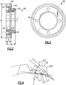
- Figure 2 shows details of the drive gear 28.
- a hub extends from end 38 to a remote end 42.
- the gear teeth 32 extend between the end 42 and a ledge 40.
- a distance d 1 can be defined along an axis I between the ends 38 and 42 and is also an axial extent of the teeth 32.
- the hub includes a mount extending from the ledge 40 to end 38.
- d 2 An axial distance between the end 42 and the end 38 is shown as d 2 .
- d 1 was 0.220 inch (0.5588 centimeters) and d 2 was 0.423 inch (1.074442 centimeters).
- a ratio of d 1 to d 2 is between 0.520 and 0.544.
- cutouts 44 are formed in an end face at remote end 42.
- a ditch 50 is shown between the threaded radially inner bore portion 46 and the radially outer bore portion 48.
- a diameter d 3 to an outer diameter of the gear teeth 32 was 1.60 inches (4.06 cm).
- a ratio of d 3 to d 1 was between 6.93 and 7.28.
- Figure 3 shows an end of the drive gear 28 and shows there are four equal spaced cutouts 44, which are all cylindrical.
- Figure 4 shows a detail of a gear tooth 32.
- the curved sides 200 include four roll angles.
- a roll angle V from a base of the side 200 to the point A is between 6.7° and 8.7°, for example 7.7.
- a roll angle X to the point B from the base of the side is between 11.1° and 13.1°, for example 12.10° in one embodiment.
- a roll angle Y to the point C is between 24.4° and 26.4°, for example 25.4° in one embodiment.
- the roll angle Z to the point D at the outer end of the side 200 is between 28.9° and 30.9°, for example 29.9°.
- Points A-D represent locations along the tooth where roll angles are inspected, with A at tooth base, and D at tooth tip.
- Figure 5 shows details of the driven gear 30.
- the gear teeth 132 are at an outer periphery and extend between an end 72 to an end 70 of a radially outwardly extending flange 60. Holes 62 extend through the flange 60.
- a generally conical portion 64 merges the flange 60 into a base or hub 66.
- the hub 66 defines a remote end 68.
- a distance d 5 is defined along a central axis J between ends 68 and 70.
- a second distance d 4 is defined along the axis J between ends 70 and 72.
- d 1 was 0.348 inch (0.88392 centimeters) and d 4 was 0.130 inch (0.3302 centimeters).
- a ratio of d 5 to d 4 was between 2.541 and 2.824.
- Figure 6 shows an end view of the gear 30. As shown, there are eight holes 62 each equally spaced about the axis J.
- the central hole 67 has opposed cylindrical portions 74 and intermediate flat portions 69.
- a distance to d 3 is defined through the axis J and between the flat portions 69.
- d 3 is .378 inch (0.96 cm).
- a ratio of d 3 to d 1 was between 1.06 and 1.10 inches (2.69 to 2.79 cm).
- the gear tooth 132 has angles L, M, N and O.
- the angle L to the point A along the side 200 was 14.42°.
- the angle L was between 13.42° and 15.42°.
- a roll angle M to the point B was 16.7°.
- the roll angle M is between 15.7° and 17.7°.
- the roll angle N to the point C was 23.54°.
- the roll angle N is between 22.54° and 24.54°.
- the roll angle O to the point D was 25.82°.
- the roll angle O is between 24.82° and 26.82°°.
- the location of the gears 30 and 28 on the respective shafts is proper.
- the roll angles result in the gears transmitting rotation more effectively.
Landscapes
- Engineering & Computer Science (AREA)
- General Engineering & Computer Science (AREA)
- Mechanical Engineering (AREA)
- Power Engineering (AREA)
- Rotary Pumps (AREA)
- Connection Of Motors, Electrical Generators, Mechanical Devices, And The Like (AREA)
Claims (6)
- Antriebszahnrad (28) zur Verwendung mit einem elektrischen Generator (24), umfassend:eine Zahnradnabe, die einen vorstehenden Randabschnitt (40) mit einer Vielzahl von Zahnradzähnen (32) an einem äußeren Umfang aufweist und um eine Mittelachse zentriert ist, und wobei die Zahnradnabe (26) eine Halterung aufweist, die sich axial von dem vorstehenden Rand (40) weg erstreckt, wobei ein erster Abstand (d1) zwischen axialen Enden der Zahnradzähne (32) definiert ist, wobei ein zweiter Abstand (d2) zwischen Enden der Zahnradnabe definiert ist, wobei die axialen Enden der Zahnradzähne (32) ein entferntes Ende (42) beinhalten, das von dem vorstehenden Rand (40) entfernt ist,dadurch gekennzeichnet, dass:
ein Verhältnis des ersten Abstands (d1) zum zweiten Abstand (d2) zwischen 0,520 und 0,544 liegt; und dadurch, dass:die Zahnradzähne (32) ein flaches radial äußeres Ende (202) und gekrümmte Seiten (200) aufweisen, wobei vier Rollwinkel (V, X, Y, Z) auf jeder der Seiten (200) vorliegen, wobei sich ein erster Rollwinkel (V) von 6,70° bis 8,70° erstreckt, sich ein zweiter Rollwinkel (X) von 11,10° bis 13,1° erstreckt, sich ein dritter Rollwinkel (Y) von 24,4° bis 26,4° erstreckt und sich ein vierter Rollwinkel (Z) von 28,9° bis 30,9° erstreckt,wobei das Antriebszahnrad (28) eine innere Bohrung aufweist, wobei sich ein mit Gewinde versehener, radial innerer Bohrungsabschnitt (46) von einer axialen Position des entfernten Endes (42) der Zähne (32) aus erstreckt, und wobei ein radial äußerer Bohrungsabschnitt (48) an der Halterung vorhanden ist,wobei ein sich radial nach außen erstreckender Graben (50) vorhanden ist, der zwischen dem mit Gewinde versehenen, radial inneren Bohrungsabschnitt (46) und dem radial äußeren Bohrungsabschnitt (48) angeordnet ist. - Antriebszahnrad (28) zur Verwendung mit einem elektrischen Generator (24) nach Anspruch 1, wobei vier gleichmäßig beabstandete zylindrische Einschnitte (44) vorhanden sind, die in dem entfernten Ende (42) ausgebildet sind.
- Ölpumpe zur Verwendung in einem elektrischen Generator (24), wobei die Ölpumpe Folgendes umfasst:einen Pumpenrotor (34);eine Antriebswelle (31) für den Pumpenrotor (34);das Antriebszahnrad (28) nach Anspruch 1 oder 2;ein getriebenes Zahnrad (30), wobei das Antriebszahnrad (28) in das getriebene Zahnrad (30) eingreift, wobei das getriebene Zahnrad (30), wiederum, in Eingriff genommen wird, um die Antriebswelle (31) des Pumpenrotors (34) zu drehen.
- Rotierende Baugruppe für einen elektrischen Generator (24), umfassend:
eine Nabe (26), wobei die Nabe (26) das Antriebszahnrad (28) nach Anspruch 1 oder 2 zum Eingreifen in ein getriebenes Zahnrad (30) trägt, wobei das getriebene Zahnrad (30) so konfiguriert ist, dass es wiederum an einer Antriebswelle (31) eines Pumpenrotors (34) befestigt ist. - Elektrischer Generator (24), umfassend:
einen Stator (300) und einen Rotor (302), wobei elektrische Bauteile an dem Stator (300) und dem Rotor (302) interagieren, um Elektrizität zu erzeugen, wenn der Rotor (302) gedreht wird, wobei der Rotor (302) eine Rotornabe (66) aufweist, wobei die Rotornabe (66) so konfiguriert ist, dass sie das Antriebszahnrad (28) nach Anspruch 1 oder 2 trägt, wobei das Antriebszahnrad (28) in ein getriebenes Zahnrad (30) eingreift, wobei das getriebene Zahnrad (30) so konfiguriert ist, dass es wiederum an einer Antriebswelle (31) eines Pumpenrotors (34) befestigt ist, wobei der Pumpenrotor (34) eine vom Generator getrennte Einheit ist. - Generator nach Anspruch 5, wobei das Antriebszahnrad (28) in das getriebene Zahnrad (30) eingreift, wobei das getriebene Zahnrad (30) wiederum an der Antriebswelle (31) und dem Pumpenrotor (34) befestigt ist, um wiederum Öl an den elektrischen Generator (24) zu liefern.
Applications Claiming Priority (1)
| Application Number | Priority Date | Filing Date | Title |
|---|---|---|---|
| US14/181,860 US9502942B2 (en) | 2014-02-17 | 2014-02-17 | Electric generator oil pump drive gear |
Publications (2)
| Publication Number | Publication Date |
|---|---|
| EP2908030A1 EP2908030A1 (de) | 2015-08-19 |
| EP2908030B1 true EP2908030B1 (de) | 2022-03-30 |
Family
ID=52473789
Family Applications (1)
| Application Number | Title | Priority Date | Filing Date |
|---|---|---|---|
| EP15155285.8A Active EP2908030B1 (de) | 2014-02-17 | 2015-02-16 | Ölpumpenantriebsrad eines elektrischen Generators |
Country Status (2)
| Country | Link |
|---|---|
| US (1) | US9502942B2 (de) |
| EP (1) | EP2908030B1 (de) |
Families Citing this family (5)
| Publication number | Priority date | Publication date | Assignee | Title |
|---|---|---|---|---|
| US10738708B2 (en) * | 2017-10-03 | 2020-08-11 | Hamilton Sundstrand Corporation | Accessory drive gear for integrated drive generator |
| CN107975396B (zh) * | 2017-11-21 | 2020-03-10 | 潍柴动力股份有限公司 | 一种发动机辅助润滑控制方法及装置 |
| US11054012B2 (en) * | 2018-01-04 | 2021-07-06 | Hamilton Sundstrand Corporation | Generator driven gear for integrated drive generator |
| US11901799B2 (en) | 2021-02-08 | 2024-02-13 | General Electric Company | Electrical machines for integration into a propulsion engine |
| US11566533B2 (en) | 2021-02-08 | 2023-01-31 | General Electric Company | Electrical machines for integration into a propulsion engine |
Family Cites Families (17)
| Publication number | Priority date | Publication date | Assignee | Title |
|---|---|---|---|---|
| US753785A (en) | 1902-02-25 | 1904-03-01 | Three Speed Gear Syndicate Ltd | Variable gearing for velocipedes or road motor-vehicles. |
| US2482110A (en) | 1946-09-11 | 1949-09-20 | Bernard E Hill | Power transmission mechanism |
| DE2828473A1 (de) | 1978-06-29 | 1980-01-17 | Bosch Gmbh Robert | Oelgekuehlte elektrische maschine |
| US4201276A (en) | 1978-11-02 | 1980-05-06 | Bardin Viktor P | Vortex-type oil mist generator |
| GB2067684B (en) | 1979-11-12 | 1983-06-08 | Yanmar Diesel Engine Co | Reduction gear for marine propulsion systems |
| JP2002295643A (ja) * | 2001-03-30 | 2002-10-09 | Fuji Photo Film Co Ltd | 駆動力伝達車 |
| JP2005088642A (ja) | 2003-09-12 | 2005-04-07 | Kawasaki Heavy Ind Ltd | 車両の油圧発生装置 |
| JP4636506B2 (ja) | 2006-02-28 | 2011-02-23 | 本田技研工業株式会社 | 車両用発電機の冷却構造 |
| US8276396B2 (en) | 2006-12-29 | 2012-10-02 | Carrier Corporation | Oil cooled generator for trailer refrigeration unit |
| US7963190B2 (en) | 2008-09-15 | 2011-06-21 | Harrier Technologies, Inc. | Helical gear sets |
| US8454326B2 (en) | 2009-05-08 | 2013-06-04 | Hamilton Sundstrand Corporation | Idler gear and journal bearing assembly for a generator |
| US8138642B2 (en) | 2009-06-17 | 2012-03-20 | Hamilton Sundstrand Corporation | Oil cooled generator |
| US7926381B2 (en) * | 2009-06-30 | 2011-04-19 | Hamilton Sundstrand Corporation | Idler gear for a generator |
| DE102010021771A1 (de) * | 2010-05-27 | 2011-12-01 | Schottel Gmbh | Kegelzahnrad eines Kegelgetriebes |
| US8424416B2 (en) | 2010-06-18 | 2013-04-23 | Hamilton Sundstrand Corporation | Layshaft generator |
| US8561503B2 (en) | 2011-07-28 | 2013-10-22 | Hamilton Sundstrand Corporation | Motor-generator and prime mover gearing assembly |
| US8624415B2 (en) | 2012-04-19 | 2014-01-07 | Hamilton Sundstrand Corporation | Multi-rotor generator |
-
2014
- 2014-02-17 US US14/181,860 patent/US9502942B2/en active Active
-
2015
- 2015-02-16 EP EP15155285.8A patent/EP2908030B1/de active Active
Also Published As
| Publication number | Publication date |
|---|---|
| US20150236565A1 (en) | 2015-08-20 |
| US9502942B2 (en) | 2016-11-22 |
| EP2908030A1 (de) | 2015-08-19 |
Similar Documents
| Publication | Publication Date | Title |
|---|---|---|
| US9502942B2 (en) | Electric generator oil pump drive gear | |
| US20100283341A1 (en) | Decoupler shaft for high speed generator | |
| CN102338212B (zh) | 行星齿轮系统中的行星轴保持 | |
| US20100283352A1 (en) | End plates for high speed generator applications | |
| EP2654185A3 (de) | Mehrrotorgenerator | |
| EP3065275B1 (de) | Gasturbinenmotor mit magnetischem getriebe | |
| US9003638B2 (en) | Method of assembling an electromechanical device in a gas-turbine engine | |
| EP3029814A3 (de) | Konzentrische ringgeneratoren | |
| US9359957B2 (en) | Planet gear for air turbine starter system | |
| EP2908029B1 (de) | Ölpumpenantriebsrad eines elektrischen Generators | |
| CN105156216A (zh) | 燃气轮机及其启动装置 | |
| RU2689229C2 (ru) | Коробка приводов агрегатов турбомашины, оснащенная центробежным насосом | |
| US10451163B2 (en) | Trim ring gear for integrated drive generator | |
| US8917003B2 (en) | Axial retention of permanent magnet rotor in high speed generator | |
| US10599165B2 (en) | Governor and inversion pump drive gear | |
| EP3467349B1 (de) | Hilfsantriebsgetriebe für integrierten antriebsgenerator | |
| EP2755304B1 (de) | Rotorgetriebemontageanordnung für einen Generator und Verfahren | |
| US10826342B2 (en) | Permanent magnet generator rotor for integrated drive generator | |
| EP3508758B1 (de) | Angetriebenes zahnrad für generator eines integrierten antriebsgenerator | |
| EP3502514B1 (de) | Abgangszahnkranz für integrierten antriebsgenerator | |
| US10760665B2 (en) | Governor drive gear for integrated drive generator | |
| US20190145406A1 (en) | Scavenge/charge pump drive gear for integrated drive generator | |
| TH83384B (th) | เครื่องจักรไฟฟ้าแบบหมุน |
Legal Events
| Date | Code | Title | Description |
|---|---|---|---|
| PUAI | Public reference made under article 153(3) epc to a published international application that has entered the european phase |
Free format text: ORIGINAL CODE: 0009012 |
|
| AK | Designated contracting states |
Kind code of ref document: A1 Designated state(s): AL AT BE BG CH CY CZ DE DK EE ES FI FR GB GR HR HU IE IS IT LI LT LU LV MC MK MT NL NO PL PT RO RS SE SI SK SM TR |
|
| AX | Request for extension of the european patent |
Extension state: BA ME |
|
| 17P | Request for examination filed |
Effective date: 20160218 |
|
| RBV | Designated contracting states (corrected) |
Designated state(s): AL AT BE BG CH CY CZ DE DK EE ES FI FR GB GR HR HU IE IS IT LI LT LU LV MC MK MT NL NO PL PT RO RS SE SI SK SM TR |
|
| 17Q | First examination report despatched |
Effective date: 20160926 |
|
| STAA | Information on the status of an ep patent application or granted ep patent |
Free format text: STATUS: EXAMINATION IS IN PROGRESS |
|
| GRAP | Despatch of communication of intention to grant a patent |
Free format text: ORIGINAL CODE: EPIDOSNIGR1 |
|
| STAA | Information on the status of an ep patent application or granted ep patent |
Free format text: STATUS: GRANT OF PATENT IS INTENDED |
|
| INTG | Intention to grant announced |
Effective date: 20211006 |
|
| GRAS | Grant fee paid |
Free format text: ORIGINAL CODE: EPIDOSNIGR3 |
|
| RAP3 | Party data changed (applicant data changed or rights of an application transferred) |
Owner name: HAMILTON SUNDSTRAND CORPORATION |
|
| GRAA | (expected) grant |
Free format text: ORIGINAL CODE: 0009210 |
|
| STAA | Information on the status of an ep patent application or granted ep patent |
Free format text: STATUS: THE PATENT HAS BEEN GRANTED |
|
| AK | Designated contracting states |
Kind code of ref document: B1 Designated state(s): AL AT BE BG CH CY CZ DE DK EE ES FI FR GB GR HR HU IE IS IT LI LT LU LV MC MK MT NL NO PL PT RO RS SE SI SK SM TR |
|
| REG | Reference to a national code |
Ref country code: GB Ref legal event code: FG4D |
|
| REG | Reference to a national code |
Ref country code: CH Ref legal event code: EP |
|
| REG | Reference to a national code |
Ref country code: DE Ref legal event code: R096 Ref document number: 602015077808 Country of ref document: DE |
|
| REG | Reference to a national code |
Ref country code: AT Ref legal event code: REF Ref document number: 1479474 Country of ref document: AT Kind code of ref document: T Effective date: 20220415 |
|
| REG | Reference to a national code |
Ref country code: IE Ref legal event code: FG4D |
|
| REG | Reference to a national code |
Ref country code: LT Ref legal event code: MG9D |
|
| PG25 | Lapsed in a contracting state [announced via postgrant information from national office to epo] |
Ref country code: SE Free format text: LAPSE BECAUSE OF FAILURE TO SUBMIT A TRANSLATION OF THE DESCRIPTION OR TO PAY THE FEE WITHIN THE PRESCRIBED TIME-LIMIT Effective date: 20220330 Ref country code: RS Free format text: LAPSE BECAUSE OF FAILURE TO SUBMIT A TRANSLATION OF THE DESCRIPTION OR TO PAY THE FEE WITHIN THE PRESCRIBED TIME-LIMIT Effective date: 20220330 Ref country code: NO Free format text: LAPSE BECAUSE OF FAILURE TO SUBMIT A TRANSLATION OF THE DESCRIPTION OR TO PAY THE FEE WITHIN THE PRESCRIBED TIME-LIMIT Effective date: 20220630 Ref country code: LT Free format text: LAPSE BECAUSE OF FAILURE TO SUBMIT A TRANSLATION OF THE DESCRIPTION OR TO PAY THE FEE WITHIN THE PRESCRIBED TIME-LIMIT Effective date: 20220330 Ref country code: HR Free format text: LAPSE BECAUSE OF FAILURE TO SUBMIT A TRANSLATION OF THE DESCRIPTION OR TO PAY THE FEE WITHIN THE PRESCRIBED TIME-LIMIT Effective date: 20220330 Ref country code: BG Free format text: LAPSE BECAUSE OF FAILURE TO SUBMIT A TRANSLATION OF THE DESCRIPTION OR TO PAY THE FEE WITHIN THE PRESCRIBED TIME-LIMIT Effective date: 20220630 |
|
| REG | Reference to a national code |
Ref country code: NL Ref legal event code: MP Effective date: 20220330 |
|
| REG | Reference to a national code |
Ref country code: AT Ref legal event code: MK05 Ref document number: 1479474 Country of ref document: AT Kind code of ref document: T Effective date: 20220330 |
|
| PG25 | Lapsed in a contracting state [announced via postgrant information from national office to epo] |
Ref country code: LV Free format text: LAPSE BECAUSE OF FAILURE TO SUBMIT A TRANSLATION OF THE DESCRIPTION OR TO PAY THE FEE WITHIN THE PRESCRIBED TIME-LIMIT Effective date: 20220330 Ref country code: GR Free format text: LAPSE BECAUSE OF FAILURE TO SUBMIT A TRANSLATION OF THE DESCRIPTION OR TO PAY THE FEE WITHIN THE PRESCRIBED TIME-LIMIT Effective date: 20220701 Ref country code: FI Free format text: LAPSE BECAUSE OF FAILURE TO SUBMIT A TRANSLATION OF THE DESCRIPTION OR TO PAY THE FEE WITHIN THE PRESCRIBED TIME-LIMIT Effective date: 20220330 |
|
| PG25 | Lapsed in a contracting state [announced via postgrant information from national office to epo] |
Ref country code: NL Free format text: LAPSE BECAUSE OF FAILURE TO SUBMIT A TRANSLATION OF THE DESCRIPTION OR TO PAY THE FEE WITHIN THE PRESCRIBED TIME-LIMIT Effective date: 20220330 |
|
| PG25 | Lapsed in a contracting state [announced via postgrant information from national office to epo] |
Ref country code: SM Free format text: LAPSE BECAUSE OF FAILURE TO SUBMIT A TRANSLATION OF THE DESCRIPTION OR TO PAY THE FEE WITHIN THE PRESCRIBED TIME-LIMIT Effective date: 20220330 Ref country code: SK Free format text: LAPSE BECAUSE OF FAILURE TO SUBMIT A TRANSLATION OF THE DESCRIPTION OR TO PAY THE FEE WITHIN THE PRESCRIBED TIME-LIMIT Effective date: 20220330 Ref country code: RO Free format text: LAPSE BECAUSE OF FAILURE TO SUBMIT A TRANSLATION OF THE DESCRIPTION OR TO PAY THE FEE WITHIN THE PRESCRIBED TIME-LIMIT Effective date: 20220330 Ref country code: PT Free format text: LAPSE BECAUSE OF FAILURE TO SUBMIT A TRANSLATION OF THE DESCRIPTION OR TO PAY THE FEE WITHIN THE PRESCRIBED TIME-LIMIT Effective date: 20220801 Ref country code: ES Free format text: LAPSE BECAUSE OF FAILURE TO SUBMIT A TRANSLATION OF THE DESCRIPTION OR TO PAY THE FEE WITHIN THE PRESCRIBED TIME-LIMIT Effective date: 20220330 Ref country code: EE Free format text: LAPSE BECAUSE OF FAILURE TO SUBMIT A TRANSLATION OF THE DESCRIPTION OR TO PAY THE FEE WITHIN THE PRESCRIBED TIME-LIMIT Effective date: 20220330 Ref country code: CZ Free format text: LAPSE BECAUSE OF FAILURE TO SUBMIT A TRANSLATION OF THE DESCRIPTION OR TO PAY THE FEE WITHIN THE PRESCRIBED TIME-LIMIT Effective date: 20220330 Ref country code: AT Free format text: LAPSE BECAUSE OF FAILURE TO SUBMIT A TRANSLATION OF THE DESCRIPTION OR TO PAY THE FEE WITHIN THE PRESCRIBED TIME-LIMIT Effective date: 20220330 |
|
| PG25 | Lapsed in a contracting state [announced via postgrant information from national office to epo] |
Ref country code: PL Free format text: LAPSE BECAUSE OF FAILURE TO SUBMIT A TRANSLATION OF THE DESCRIPTION OR TO PAY THE FEE WITHIN THE PRESCRIBED TIME-LIMIT Effective date: 20220330 Ref country code: IS Free format text: LAPSE BECAUSE OF FAILURE TO SUBMIT A TRANSLATION OF THE DESCRIPTION OR TO PAY THE FEE WITHIN THE PRESCRIBED TIME-LIMIT Effective date: 20220730 Ref country code: AL Free format text: LAPSE BECAUSE OF FAILURE TO SUBMIT A TRANSLATION OF THE DESCRIPTION OR TO PAY THE FEE WITHIN THE PRESCRIBED TIME-LIMIT Effective date: 20220330 |
|
| REG | Reference to a national code |
Ref country code: DE Ref legal event code: R097 Ref document number: 602015077808 Country of ref document: DE |
|
| PG25 | Lapsed in a contracting state [announced via postgrant information from national office to epo] |
Ref country code: DK Free format text: LAPSE BECAUSE OF FAILURE TO SUBMIT A TRANSLATION OF THE DESCRIPTION OR TO PAY THE FEE WITHIN THE PRESCRIBED TIME-LIMIT Effective date: 20220330 |
|
| PLBE | No opposition filed within time limit |
Free format text: ORIGINAL CODE: 0009261 |
|
| STAA | Information on the status of an ep patent application or granted ep patent |
Free format text: STATUS: NO OPPOSITION FILED WITHIN TIME LIMIT |
|
| 26N | No opposition filed |
Effective date: 20230103 |
|
| PG25 | Lapsed in a contracting state [announced via postgrant information from national office to epo] |
Ref country code: SI Free format text: LAPSE BECAUSE OF FAILURE TO SUBMIT A TRANSLATION OF THE DESCRIPTION OR TO PAY THE FEE WITHIN THE PRESCRIBED TIME-LIMIT Effective date: 20220330 |
|
| P01 | Opt-out of the competence of the unified patent court (upc) registered |
Effective date: 20230522 |
|
| PG25 | Lapsed in a contracting state [announced via postgrant information from national office to epo] |
Ref country code: IT Free format text: LAPSE BECAUSE OF FAILURE TO SUBMIT A TRANSLATION OF THE DESCRIPTION OR TO PAY THE FEE WITHIN THE PRESCRIBED TIME-LIMIT Effective date: 20220330 |
|
| REG | Reference to a national code |
Ref country code: DE Ref legal event code: R119 Ref document number: 602015077808 Country of ref document: DE |
|
| PG25 | Lapsed in a contracting state [announced via postgrant information from national office to epo] |
Ref country code: MC Free format text: LAPSE BECAUSE OF FAILURE TO SUBMIT A TRANSLATION OF THE DESCRIPTION OR TO PAY THE FEE WITHIN THE PRESCRIBED TIME-LIMIT Effective date: 20220330 |
|
| REG | Reference to a national code |
Ref country code: CH Ref legal event code: PL |
|
| REG | Reference to a national code |
Ref country code: BE Ref legal event code: MM Effective date: 20230228 |
|
| PG25 | Lapsed in a contracting state [announced via postgrant information from national office to epo] |
Ref country code: LU Free format text: LAPSE BECAUSE OF NON-PAYMENT OF DUE FEES Effective date: 20230216 Ref country code: LI Free format text: LAPSE BECAUSE OF NON-PAYMENT OF DUE FEES Effective date: 20230228 Ref country code: CH Free format text: LAPSE BECAUSE OF NON-PAYMENT OF DUE FEES Effective date: 20230228 |
|
| REG | Reference to a national code |
Ref country code: IE Ref legal event code: MM4A |
|
| PG25 | Lapsed in a contracting state [announced via postgrant information from national office to epo] |
Ref country code: IE Free format text: LAPSE BECAUSE OF NON-PAYMENT OF DUE FEES Effective date: 20230216 Ref country code: DE Free format text: LAPSE BECAUSE OF NON-PAYMENT OF DUE FEES Effective date: 20230901 |
|
| PG25 | Lapsed in a contracting state [announced via postgrant information from national office to epo] |
Ref country code: BE Free format text: LAPSE BECAUSE OF NON-PAYMENT OF DUE FEES Effective date: 20230228 |
|
| PG25 | Lapsed in a contracting state [announced via postgrant information from national office to epo] |
Ref country code: CY Free format text: LAPSE BECAUSE OF FAILURE TO SUBMIT A TRANSLATION OF THE DESCRIPTION OR TO PAY THE FEE WITHIN THE PRESCRIBED TIME-LIMIT; INVALID AB INITIO Effective date: 20150216 |
|
| PG25 | Lapsed in a contracting state [announced via postgrant information from national office to epo] |
Ref country code: HU Free format text: LAPSE BECAUSE OF FAILURE TO SUBMIT A TRANSLATION OF THE DESCRIPTION OR TO PAY THE FEE WITHIN THE PRESCRIBED TIME-LIMIT; INVALID AB INITIO Effective date: 20150216 |
|
| PG25 | Lapsed in a contracting state [announced via postgrant information from national office to epo] |
Ref country code: TR Free format text: LAPSE BECAUSE OF FAILURE TO SUBMIT A TRANSLATION OF THE DESCRIPTION OR TO PAY THE FEE WITHIN THE PRESCRIBED TIME-LIMIT Effective date: 20220330 |
|
| PGFP | Annual fee paid to national office [announced via postgrant information from national office to epo] |
Ref country code: GB Payment date: 20260122 Year of fee payment: 12 |
|
| PGFP | Annual fee paid to national office [announced via postgrant information from national office to epo] |
Ref country code: FR Payment date: 20260121 Year of fee payment: 12 |