EP2907982A1 - Cam follower for an internal combustion engine - Google Patents
Cam follower for an internal combustion engine Download PDFInfo
- Publication number
- EP2907982A1 EP2907982A1 EP14155193.7A EP14155193A EP2907982A1 EP 2907982 A1 EP2907982 A1 EP 2907982A1 EP 14155193 A EP14155193 A EP 14155193A EP 2907982 A1 EP2907982 A1 EP 2907982A1
- Authority
- EP
- European Patent Office
- Prior art keywords
- roll
- cam follower
- bushing
- face
- chamfer
- Prior art date
- Legal status (The legal status is an assumption and is not a legal conclusion. Google has not performed a legal analysis and makes no representation as to the accuracy of the status listed.)
- Withdrawn
Links
Images

Classifications
-
- F—MECHANICAL ENGINEERING; LIGHTING; HEATING; WEAPONS; BLASTING
- F01—MACHINES OR ENGINES IN GENERAL; ENGINE PLANTS IN GENERAL; STEAM ENGINES
- F01L—CYCLICALLY OPERATING VALVES FOR MACHINES OR ENGINES
- F01L1/00—Valve-gear or valve arrangements, e.g. lift-valve gear
- F01L1/12—Transmitting gear between valve drive and valve
- F01L1/18—Rocking arms or levers
-
- F—MECHANICAL ENGINEERING; LIGHTING; HEATING; WEAPONS; BLASTING
- F01—MACHINES OR ENGINES IN GENERAL; ENGINE PLANTS IN GENERAL; STEAM ENGINES
- F01L—CYCLICALLY OPERATING VALVES FOR MACHINES OR ENGINES
- F01L1/00—Valve-gear or valve arrangements, e.g. lift-valve gear
- F01L1/12—Transmitting gear between valve drive and valve
- F01L1/14—Tappets; Push rods
-
- F—MECHANICAL ENGINEERING; LIGHTING; HEATING; WEAPONS; BLASTING
- F01—MACHINES OR ENGINES IN GENERAL; ENGINE PLANTS IN GENERAL; STEAM ENGINES
- F01L—CYCLICALLY OPERATING VALVES FOR MACHINES OR ENGINES
- F01L2305/00—Valve arrangements comprising rollers
-
- F—MECHANICAL ENGINEERING; LIGHTING; HEATING; WEAPONS; BLASTING
- F01—MACHINES OR ENGINES IN GENERAL; ENGINE PLANTS IN GENERAL; STEAM ENGINES
- F01L—CYCLICALLY OPERATING VALVES FOR MACHINES OR ENGINES
- F01L2305/00—Valve arrangements comprising rollers
- F01L2305/02—Mounting of rollers
Definitions
- the present disclosure generally relates to internal combustion engines, in particular, to a cam follower for an internal combustion engine.
- a camshaft of the internal combustion engine comprises a plurality of cams, and the opening and closing of the inlet valves and outlet valves is controlled by a plurality of cam followers, which trace a movement of an associated cam.
- a cam follower includes a roll that rolls on the cam. The movement of the roll on the cam is transmitted to, for example, an inlet valve or an outlet valve by a rod connected to the cam follower.
- the present disclosure is directed, at least in part, to improving or overcoming one or more aspects of prior systems.
- a cam follower for an internal combustion engine comprises a bracket, an axis mounted on the bracket and a roll rotatably mounted on the axis.
- the roll extends in a longitudinal direction with a wall thickness and includes an outer surface, an inner surface, a first end face, a second end face and a relief chamfer extending radially inward from at least one of the first end face and the second end face to the inner surface.
- the relief chamfer has a length in the longitudinal direction and a height in the radial direction such that a ratio of the product of the length and the height to the square of the wall thickness is greater than about 0.05.
- an internal combustion engine comprises a camshaft including at least one cam and at least one cam follower.
- the at least one cam follower comprises a bracket, an axis mounted on the bracket and a roll rotatably mounted on the axis.
- the roll extends in a longitudinal direction with a wall thickness and includes an outer surface, an inner surface, a first end face, a second end face and a relief chamfer extending radially inward from at least one of the first end face and the second end face to the inner surface.
- the relief chamfer has a length in the longitudinal direction and a height in the radial direction such that a ratio of the product of the length and the height to the square of the wall thickness is greater than about 0.05.
- the present disclosure may be based in part on the realization that, when a roll having a cylindrical body is rotatable mounted on a corresponding axis of a cam follower, a force applied from the camshaft to the cylindrical roll may result in an application of end pressures on the ends of the cylindrical roll. Further, if the roll is mounted on the axis via a bushing, end pressures may also be applied to the ends of the bushing.
- the end pressures applied to the ends of the roll and the optional bushing can be reduced or avoided by providing a recessed portion adjacent to the ends of the roll such that the ends of the roll are not in direct contact with the axis or the optional bushing.
- a recess formed in the bushing can also serve to relieve the ends of the bushing and/or the associated roll.
- the stiffness of the roll and/or the bushing near the ends of the same can be reduced to reduce or avoid pressing of the ends of the roll and/or the bushing.
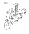
- Fig. 1 schematically shows a cam follower assembly for an internal combustion engine.
- the internal combustion engine includes a camshaft 10 having a plurality of cams 12, 14, 16.
- a plurality of cam followers 18, 20, 22 are arranged to trace the movement of cams 12, 14, 16 by contacting the same.
- Cam 12 may operate, for example, an inlet valve arranged in an inlet of a combustion chamber of a cylinder of the internal combustion engine via cam follower 18.
- Cam 14 may operate, for example, an outlet valve arranged in an outlet of the combustion chamber via cam follower 20.
- Cam 16 may operate, for example, an injection device for injecting fuel into the combustion chamber via cam follower 22. It should be appreciated that the above example is not intended to limit the present disclosure to the configuration shown in Fig. 1 , and that one or more of cams 12, 14, 16 and cam followers 18, 20, 22 may be omitted.
- Cam follower 18 comprises an operating lever formed, for example, as an oscillating arm which may trace the stroke of cam 12 via a roll 25 supported on a bracket 26 and transmit the same to the inlet valve via a rod 28.
- cam follower 20 is provided with an operating lever including a bracket 30 and may trace the stroke of cam 14 via a roll 29 supported on bracket 30 and transmit the same to the outlet valve via a rod 32.
- the stroke of cam 16 may be traced by a roll 33 mounted on a bracket 34 arranged at the end of an operating lever of cam follower 22 and transmitted to the injection device by a piston 24.
- the operating levers are rotatably supported, for example, on disks 36, 38, 40.
- the timings of the inlet valve and the outlet valve and, optionally, the injection timing may be controlled by adjusting, for example, the positions of disks 36, 38, 40, which may be formed as eccentrics.
- cam follower 18 is shown in more detail. It should be appreciated that the configuration of cam followers 20, 22 may be identical to the configuration of cam follower 18.
- cam follower 18 includes bracket 26, roll 25, a bushing 27 and an axis 23 mounted on bracket 26.
- Axis 23 is fixedly mounted in bores of bracket 26, for example, by press fitting or the like.
- Bushing 27 is mounted on axis 23.
- roll 25 is rotatably mounted on bushing 27 in a known manner. It will be appreciated that, in other embodiments, bushing 27 may be omitted, and roll 25 may be directly mounted on axis 23.
- Roll 25 is configured to roll on cam 12 upon rotation of camshaft 10. When camshaft 10 rotates, movement of roll 25 is transmitted to, for example, the inlet valve of the associated cylinder via rod 28.
- roll 25 may receive impact forces from cam 12. This may lead to end pressures being applied to the ends of roll 25.
- roll 25 includes recesses formed at the ends of the same.
- the recesses are formed as relief chamfers 41, 43. This increases the flexibility of roll 25 near the ends of the same, and reduces the end pressures applied to roll 25 and the optional bushing 27 during rotation of camshaft 10. In particular, it reduces or avoids pressing of the ends of roll 25 against the ends of bushing 27 (or axis 23 in case bushing 27 is omitted) at a contact interface 42 formed between roll 25 and bushing 27 (or between roll 25 and axis 23 in case bushing 27 is omitted).
- roll 25 includes a hollow cylindrical body having an outer surface 25a, an inner surface 25b, a first end face 25c and a second end face 25d. Roll 25 extends along a longitudinal direction parallel to axis 23 with a length 1 from first end face 25c to second end face 25d. Further, the hollow cylindrical body of roll 25 has a wall thickness t.
- bushing 27 is formed as a hollow cylindrical body and extends along the longitudinal direction of axis 23 with the same length 1 as roll 25. It should be appreciated that in other embodiments a length of bushing 27 can be different from the length 1 of roll 25.
- Bushing 27 also includes an outer surface 27a, an inner surface 27b, a first end face 27c adjacent to first end face 25c of roll 25 and a second end face 27d adjacent to second end face 25d of roll 25.
- contact interface 42 is formed between inner surface 25b of roll 25 and outer surface 27a of bushing 27. It should be appreciated that, in case bushing 27 is omitted, contact interface 42 will be formed between roll 25 and axis 23.
- the term "contact interface” refers to the surfaces of roll 25 and bushing 27 or axis 23 that are in contact during tracing of the movement of cam 12 by cam follower 18.
- the term "the contact interface includes a recess” is to be understood such that a recess is formed in one of the surfaces forming the contact interface. In other words, this term is to be understood such that a recess is formed in at least one of inner surface 25b of roll 25 and outer surface 27a of bushing 27, if present.
- the end pressure at the ends of roll 25 is reduced or avoided by providing a recessed portion of contact interface 42 adjacent to first and/or second end faces 25c, 25d of roll 25.
- the recessed portion is formed as relief chamfers 41, 43.
- Each of relief chamfers 41, 43 is formed at one end of roll 25 in the longitudinal direction and extends radially inward from the associated one of first and second end faces 25c, 25d to inner surface 25b of roll 25. It is obvious that relief chamfers 41, 43 are formed to extend in the circumferential direction of roll 25, i.e., as a continuous relief chamfer that extends circumferentially.
- each of relief chamfers 41, 43 has an extension d in the longitudinal direction and an extension h in the radial direction.
- the extension d will be referred to as the length of the chamfer
- the extension h will be referred to as the height of the chamfer.
- Each of relief chamfers 41, 43 has a size such that a ratio of the product of the length d and the height h to the square of the wall thickness t is greater than about 0.05.
- the amount of material that is removed when relief chamfers 41, 43 are formed has a predetermined relation to the thickness of roll 25. According to the present disclosure, a substantial amount of material is removed in order to achieve the desired flexibility of the ends of roll 25.
- the relation may be such that the ratio of the product of the length d and the height h to the square of the wall thickness t is greater than a predetermined value, for example, about 0.05 or about 0.1. This may be achieved, for example, by providing each of relief chamfers 41, 43 with a length d that is greater than about 0.25 times the wall thickness t and/or a height h that is greater than about 0.25 times the wall thickness t.
- the recessed portion of the contact interface 42 is formed as relief chamfers 41, 43 including a chamfered surface extending from end faces 25c, 25d to inner surface 25b.
- the relief chamfers may be formed as a step, i.e., with a rectangular cross-section.
- the relief chamfers may include a curved surface, for example, a concave or convex surface extending from end faces 25c, 25d to inner surface 25b.
- the relation between the height h and the length d of the relief chamfers to the wall thickness t may be the same as for relief chamfers 41, 43.
- the relief chamfers may be formed by machining end faces 25c, 25d in an appropriate manner, for example, by end milling or the like.
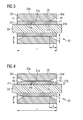
- Fig. 4 another exemplary embodiment of cam follower 18 is shown in more detail.
- roll 25 and bushing 27 substantially have the same configuration as in the embodiment shown in Fig. 3 such that only the differences will be described.
- a further recessed portion of contact interface 42 is formed in bushing 27.
- chamfers 45, 47 are formed adjacent to end faces 27c, 27d of bushing 27 to substantially face relief chamfers 41, 43 of roll 25.
- each of chamfers 45, 47 may have a length in the longitudinal direction that is the same as the length d of chamfers 41, 43.
- the length of chamfers 41, 43 and chamfers 45, 47 may be different.
- Chamfers 45 and 47 may have the same or a different shape as chamfers 41, 43.
- each of relief chamfers 45, 47 may have a size such that a ratio of the product of the length and the height of the same to the square of the wall thickness of bushing 27 is greater than about 0.05, for example, greater than about 0.1.
- the end pressures at the ends of roll 25 due to impact forces received from cam 12 can be reduced even further.
- the recesses in bushing 27 may also be formed as steps or curved surfaces.
- the recessed portion of the contact interface included chamfers 41, 43 or similar recesses formed in roll 25, it is also contemplated that, in case bushing 27 is present, the recessed portion of contact interface 42 may only be formed in bushing 27. In other words, no relief chamfers 41, 43 or similar recesses may be formed in roll 25. However, it is preferable that such recesses are formed in roll 25 adjacent to end faces 25c, 25d to achieve the desired flexibility of roll 25.
- the structure of the roll of the cam follower according to the present disclosure it is possible to reduce or avoid end pressures being applied to the ends of the roll due to impact forces received from the associated cam. This may improve the durability and reliability of the cam follower including the roll.
- relief chamfers are formed in the end faces of the roll to improve the flexibility of the ends of the same. Further, in case the roll is mounted on the corresponding axis via a bushing, the end pressures may further be reduced by also providing relief chamfers in the bushing facing the relief chamfers of the roll. This may be applied both to rolls with and without a crowned profile.
Abstract
A cam follower (18) for internal combustion engine comprises a bracket (26), an axis (23) mounted on the bracket (26) and a roll (25) rotatably mounted on the axis (23). The roll (25) has a wall thickness. Relief chamfers (41, 43) extend from the end faces of the roll (25) with a length in the longitudinal direction and a height in the radial direction such that a ratio of product of the length and the height to the square of the wall thickness is greater than about 0.05.
Description
- The present disclosure generally relates to internal combustion engines, in particular, to a cam follower for an internal combustion engine.
- Various technologies are known for adjusting, for example, the opening and closing of inlet valves and outlet valves of internal combustion engines.
- Generally, a camshaft of the internal combustion engine comprises a plurality of cams, and the opening and closing of the inlet valves and outlet valves is controlled by a plurality of cam followers, which trace a movement of an associated cam. Such a cam follower includes a roll that rolls on the cam. The movement of the roll on the cam is transmitted to, for example, an inlet valve or an outlet valve by a rod connected to the cam follower.
- The present disclosure is directed, at least in part, to improving or overcoming one or more aspects of prior systems.
- According to one aspect, a cam follower for an internal combustion engine comprises a bracket, an axis mounted on the bracket and a roll rotatably mounted on the axis. The roll extends in a longitudinal direction with a wall thickness and includes an outer surface, an inner surface, a first end face, a second end face and a relief chamfer extending radially inward from at least one of the first end face and the second end face to the inner surface. The relief chamfer has a length in the longitudinal direction and a height in the radial direction such that a ratio of the product of the length and the height to the square of the wall thickness is greater than about 0.05.
- According to another aspect, an internal combustion engine comprises a camshaft including at least one cam and at least one cam follower. The at least one cam follower comprises a bracket, an axis mounted on the bracket and a roll rotatably mounted on the axis. The roll extends in a longitudinal direction with a wall thickness and includes an outer surface, an inner surface, a first end face, a second end face and a relief chamfer extending radially inward from at least one of the first end face and the second end face to the inner surface. The relief chamfer has a length in the longitudinal direction and a height in the radial direction such that a ratio of the product of the length and the height to the square of the wall thickness is greater than about 0.05.
- Other features and aspects of the present disclosure will be apparent from the following description and the accompanying drawings.
-
-
Fig. 1 is a schematic view of an exemplary cam follower assembly for an internal combustion engine; -
Fig. 2 is a schematic cross-sectional view of an exemplary cam follower for an internal combustion engine; -
Fig. 3 is a detailed view of a part of the cam follower ofFig. 2 ; and -
Fig. 4 is a detailed view of a part of another exemplary cam follower according to the present disclosure. - The following is a detailed description of exemplary embodiments of the present disclosure. The exemplary embodiments described herein are intended to teach the principles of the present disclosure, enabling those of ordinary skill in the art to implement and use the present disclosure in many different environments and for many different applications. Therefore, the exemplary embodiments are not intended to be, and should not be considered as a limiting description of the scope of protection. Rather, the scope of protection shall be defined by the appended claims.
- The present disclosure may be based in part on the realization that, when a roll having a cylindrical body is rotatable mounted on a corresponding axis of a cam follower, a force applied from the camshaft to the cylindrical roll may result in an application of end pressures on the ends of the cylindrical roll. Further, if the roll is mounted on the axis via a bushing, end pressures may also be applied to the ends of the bushing.
- According to the present disclosure, the end pressures applied to the ends of the roll and the optional bushing can be reduced or avoided by providing a recessed portion adjacent to the ends of the roll such that the ends of the roll are not in direct contact with the axis or the optional bushing.
- Further, the present disclosure may be based at least in part on the realization that, when a bushing is mounted between the roll and the axis, a recess formed in the bushing can also serve to relieve the ends of the bushing and/or the associated roll.
- By providing the above-described recesses, the stiffness of the roll and/or the bushing near the ends of the same can be reduced to reduce or avoid pressing of the ends of the roll and/or the bushing.
- Referring now to the drawings,
Fig. 1 schematically shows a cam follower assembly for an internal combustion engine. As shown inFig. 1 , the internal combustion engine includes acamshaft 10 having a plurality ofcams cam followers cams -
Cam 12 may operate, for example, an inlet valve arranged in an inlet of a combustion chamber of a cylinder of the internal combustion engine viacam follower 18.Cam 14 may operate, for example, an outlet valve arranged in an outlet of the combustion chamber viacam follower 20.Cam 16 may operate, for example, an injection device for injecting fuel into the combustion chamber viacam follower 22. It should be appreciated that the above example is not intended to limit the present disclosure to the configuration shown inFig. 1 , and that one or more ofcams cam followers -
Cam follower 18 comprises an operating lever formed, for example, as an oscillating arm which may trace the stroke ofcam 12 via aroll 25 supported on abracket 26 and transmit the same to the inlet valve via arod 28. - In a similar manner,
cam follower 20 is provided with an operating lever including abracket 30 and may trace the stroke ofcam 14 via aroll 29 supported onbracket 30 and transmit the same to the outlet valve via arod 32. - The stroke of
cam 16 may be traced by aroll 33 mounted on abracket 34 arranged at the end of an operating lever ofcam follower 22 and transmitted to the injection device by apiston 24. - At their opposite ends, the operating levers are rotatably supported, for example, on
disks disks - Referring now to
Fig. 2 ,cam follower 18 is shown in more detail. It should be appreciated that the configuration ofcam followers cam follower 18. - As shown in
Fig. 2 ,cam follower 18 includesbracket 26,roll 25, a bushing 27 and anaxis 23 mounted onbracket 26. -
Axis 23 is fixedly mounted in bores ofbracket 26, for example, by press fitting or the like.Bushing 27 is mounted onaxis 23. In addition,roll 25 is rotatably mounted on bushing 27 in a known manner. It will be appreciated that, in other embodiments, bushing 27 may be omitted, androll 25 may be directly mounted onaxis 23.Roll 25 is configured to roll oncam 12 upon rotation ofcamshaft 10. Whencamshaft 10 rotates, movement ofroll 25 is transmitted to, for example, the inlet valve of the associated cylinder viarod 28. - During operation of the internal combustion engine,
roll 25 may receive impact forces fromcam 12. This may lead to end pressures being applied to the ends ofroll 25. - In order to reduce or avoid wear of the components of
cam follower 18 due to these end pressures,roll 25 includes recesses formed at the ends of the same. In the exemplary embodiment shown inFig. 2 , the recesses are formed asrelief chamfers roll 25 near the ends of the same, and reduces the end pressures applied to roll 25 and theoptional bushing 27 during rotation ofcamshaft 10. In particular, it reduces or avoids pressing of the ends ofroll 25 against the ends of bushing 27 (oraxis 23 in case bushing 27 is omitted) at acontact interface 42 formed betweenroll 25 and bushing 27 (or betweenroll 25 andaxis 23 in case bushing 27 is omitted). - Referring to
Fig. 3 ,roll 25 and the associatedbushing 27 ofcam follower 18 are shown in more detail. - As shown in
Fig. 3 ,roll 25 includes a hollow cylindrical body having anouter surface 25a, aninner surface 25b, afirst end face 25c and asecond end face 25d.Roll 25 extends along a longitudinal direction parallel toaxis 23 with a length 1 fromfirst end face 25c tosecond end face 25d. Further, the hollow cylindrical body ofroll 25 has a wall thickness t. - Similarly, bushing 27 is formed as a hollow cylindrical body and extends along the longitudinal direction of
axis 23 with the same length 1 asroll 25. It should be appreciated that in other embodiments a length of bushing 27 can be different from the length 1 ofroll 25.Bushing 27 also includes anouter surface 27a, aninner surface 27b, afirst end face 27c adjacent tofirst end face 25c ofroll 25 and asecond end face 27d adjacent tosecond end face 25d ofroll 25. - As shown in
Fig. 3 ,contact interface 42 is formed betweeninner surface 25b ofroll 25 andouter surface 27a ofbushing 27. It should be appreciated that, incase bushing 27 is omitted,contact interface 42 will be formed betweenroll 25 andaxis 23. As used herein, the term "contact interface" refers to the surfaces ofroll 25 andbushing 27 oraxis 23 that are in contact during tracing of the movement ofcam 12 bycam follower 18. Further, the term "the contact interface includes a recess" is to be understood such that a recess is formed in one of the surfaces forming the contact interface. In other words, this term is to be understood such that a recess is formed in at least one ofinner surface 25b ofroll 25 andouter surface 27a ofbushing 27, if present. - According to the present disclosure, the end pressure at the ends of
roll 25 is reduced or avoided by providing a recessed portion ofcontact interface 42 adjacent to first and/or second end faces 25c, 25d ofroll 25. - In the exemplary embodiment shown in
Fig. 3 , the recessed portion is formed asrelief chamfers relief chamfers roll 25 in the longitudinal direction and extends radially inward from the associated one of first and second end faces 25c, 25d toinner surface 25b ofroll 25. It is obvious that relief chamfers 41, 43 are formed to extend in the circumferential direction ofroll 25, i.e., as a continuous relief chamfer that extends circumferentially. - As shown in
Fig. 3 , each ofrelief chamfers relief chamfers roll 25. According to the present disclosure, a substantial amount of material is removed in order to achieve the desired flexibility of the ends ofroll 25. It will be readily appreciated by the skilled person that many different combinations of the length d and the height h are possible to result in the desired amount of material. Generally, as mentioned above, the relation may be such that the ratio of the product of the length d and the height h to the square of the wall thickness t is greater than a predetermined value, for example, about 0.05 or about 0.1. This may be achieved, for example, by providing each ofrelief chamfers - In the embodiment shown in
Fig. 3 , the recessed portion of thecontact interface 42 is formed asrelief chamfers inner surface 25b. It will be readily appreciated that, in other embodiments, the relief chamfers may be formed as a step, i.e., with a rectangular cross-section. In other embodiments, the relief chamfers may include a curved surface, for example, a concave or convex surface extending from end faces 25c, 25d toinner surface 25b. The relation between the height h and the length d of the relief chamfers to the wall thickness t, however, may be the same as forrelief chamfers - Turning now to
Fig. 4 , another exemplary embodiment ofcam follower 18 is shown in more detail. In the embodiment shown inFig. 4 , roll 25 andbushing 27 substantially have the same configuration as in the embodiment shown inFig. 3 such that only the differences will be described. - In the embodiment shown in
Fig. 4 , a further recessed portion ofcontact interface 42 is formed inbushing 27. In particular, chamfers 45, 47 are formed adjacent to endfaces bushing 27 to substantially facerelief chamfers roll 25. As shown inFig. 4 , each ofchamfers chamfers chamfers chamfers chamfers relief chamfers bushing 27 is greater than about 0.05, for example, greater than about 0.1. By providingadditional chamfers roll 25 due to impact forces received from cam 12 (seeFig. 2 ) can be reduced even further. It should be appreciated that, instead of being formed aschamfers bushing 27 may also be formed as steps or curved surfaces. - While in the exemplary embodiments described so far, the recessed portion of the contact interface included
chamfers roll 25, it is also contemplated that, incase bushing 27 is present, the recessed portion ofcontact interface 42 may only be formed inbushing 27. In other words, norelief chamfers roll 25. However, it is preferable that such recesses are formed inroll 25 adjacent to endfaces roll 25. - The industrial applicability of the systems and methods decribed herein will be readily appreciated from the foregoing discussion.
- In particular, with the structure of the roll of the cam follower according to the present disclosure, it is possible to reduce or avoid end pressures being applied to the ends of the roll due to impact forces received from the associated cam. This may improve the durability and reliability of the cam follower including the roll.
- Advantageously, relief chamfers are formed in the end faces of the roll to improve the flexibility of the ends of the same. Further, in case the roll is mounted on the corresponding axis via a bushing, the end pressures may further be reduced by also providing relief chamfers in the bushing facing the relief chamfers of the roll. This may be applied both to rolls with and without a crowned profile.
- It will be appreciated that the foregoing description provides examples of the disclosed systems and methods. However, it is contemplated that other implementations of the disclosure may differ in detail from the foregoing examples. All references to the disclosure or examples thereof are intended to reference the particular example being discussed at that point and are not intended to imply any limitation as to the general disclosure.
- Recitation of ranges of values herein are merely intended to serve as a shorthand method for referring individually to each separate value falling within the range, unless otherwise indicated herein, and each separate value is incorporated into the specification as if it were individually recited herein. All method steps described herein can be performed in any suitable order, unless otherwise indicated or clearly contradicted by the context.
- Although the preferred embodiments of the present disclosure have been described herein, improvements and modifications may be incorporated without departing from the scope of the following claims.
Claims (15)
- A cam follower (18, 20, 22) for an internal combustion engine, comprising:a bracket (26, 30, 34);an axis (23) mounted on the bracket (26, 30, 34); anda roll (25, 29, 33) rotatably mounted on the axis (23), the roll (25, 29, 33) extending in a longitudinal direction with a wall thickness (t) and including an outer surface (25a), an inner surface (25b), a first end face (25c), a second end face (25d) and a relief chamfer (41, 43) extending radially inward from at least one of the first end face (25c) and the second end face (25d) to the inner surface (25b),wherein the relief chamfer (41, 43) has a length (d) in the longitudinal direction and a height (h) in the radial direction such that a ratio of the product of the length (d) and the height (h) to the square of the wall thickness (t) is greater than about 0.05.
- The cam follower of claim 1, wherein the relief chamfer (41, 43) extends in the longitudinal direction with a length (d) that is greater than about 0.25 times the wall thickness (t).
- The cam follower of claim 1 or 2, wherein the relief chamfer (41, 43) extends in the radial direction with a height (h) that is greater than about 0.25 times the wall thickness (t).
- The cam follower of claim any one of claims 1 to 3,
wherein the ratio is greater than about 0.1. - The cam follower of any one of claims 1 to 4, further comprising a bushing (27) mounted on the axis (23) and rotatably supporting the roll (25, 29, 33).
- The cam follower of claim 5, wherein the bushing (27) includes a chamfer (45, 47) extending radially outward from one of a first end face (27c) and a second end face (27d) of the bushing (27), the chamfer (45, 47) having a length in the longitudinal direction and a height in the radial direction such that a ratio of the product of the length and the height to the square of a wall thickness of the bushing (27) is greater than about 0.05, for example, greater than about 0.1.
- The cam follower of claim 6, wherein the chamfer (45, 47) of the bushing (27) has a length in the longitudinal direction that is substantially the same as the length (d) of the relief chamfer (41, 43) of the roll (25, 29, 33).
- The cam follower of claim 6 or 7, wherein the chamfer (45, 47) of the bushing (27) includes at least one of a stepped portion or an arcuate surface.
- The cam follower of any one of claims 1 to 8, wherein the relief chamfer (41, 43) is a first relief chamfer (41) extending from the first end face (25c), the roll (25, 29, 33) further including a second relief chamfer (43) extending radially inward from the second end face (25d).
- The cam follower of claim 9, wherein the first relief chamfer (41) and the second relief chamfer (43) have the same configuration.
- The cam follower of any one of the preceding claims,
wherein the roll (25, 29, 33) has a crowned profile. - The cam follower of any one of the preceding claims,
wherein the relief chamfer (41, 43) includes a stepped portion. - The cam follower of any one of the preceding claims,
wherein the relief chamfer (41, 43) includes an arcuate surface. - The cam follower of claim 12, wherein the arcuate surface includes a concave and/or convex surface extending from the at least one of the first end face (25c) and the second end face (25d) to the inner surface (25b).
- An internal combustion engine, comprising:a camshaft (10) including at least one cam (12, 14, 16); andat least one cam follower (18, 20, 22) according to any one of claims 1 to 14.
Priority Applications (2)
| Application Number | Priority Date | Filing Date | Title |
|---|---|---|---|
| EP14155193.7A EP2907982A1 (en) | 2014-02-14 | 2014-02-14 | Cam follower for an internal combustion engine |
| CN201520101818.2U CN204476489U (en) | 2014-02-14 | 2015-02-12 | For the cam follower of internal-combustion engine |
Applications Claiming Priority (1)
| Application Number | Priority Date | Filing Date | Title |
|---|---|---|---|
| EP14155193.7A EP2907982A1 (en) | 2014-02-14 | 2014-02-14 | Cam follower for an internal combustion engine |
Publications (1)
| Publication Number | Publication Date |
|---|---|
| EP2907982A1 true EP2907982A1 (en) | 2015-08-19 |
Family
ID=50101779
Family Applications (1)
| Application Number | Title | Priority Date | Filing Date |
|---|---|---|---|
| EP14155193.7A Withdrawn EP2907982A1 (en) | 2014-02-14 | 2014-02-14 | Cam follower for an internal combustion engine |
Country Status (2)
| Country | Link |
|---|---|
| EP (1) | EP2907982A1 (en) |
| CN (1) | CN204476489U (en) |
Citations (3)
| Publication number | Priority date | Publication date | Assignee | Title |
|---|---|---|---|---|
| JPH11247845A (en) * | 1998-02-27 | 1999-09-14 | Nippon Seiko Kk | Bearing device for roller support |
| EP1574677A1 (en) * | 2004-03-10 | 2005-09-14 | Toyota Jidosha Kabushiki Kaisha | Valve train with roller rocker arm |
| JP2007333025A (en) * | 2006-06-13 | 2007-12-27 | Nsk Ltd | Manufacturing method of rolling/sliding component |
-
2014
- 2014-02-14 EP EP14155193.7A patent/EP2907982A1/en not_active Withdrawn
-
2015
- 2015-02-12 CN CN201520101818.2U patent/CN204476489U/en not_active Expired - Fee Related
Patent Citations (3)
| Publication number | Priority date | Publication date | Assignee | Title |
|---|---|---|---|---|
| JPH11247845A (en) * | 1998-02-27 | 1999-09-14 | Nippon Seiko Kk | Bearing device for roller support |
| EP1574677A1 (en) * | 2004-03-10 | 2005-09-14 | Toyota Jidosha Kabushiki Kaisha | Valve train with roller rocker arm |
| JP2007333025A (en) * | 2006-06-13 | 2007-12-27 | Nsk Ltd | Manufacturing method of rolling/sliding component |
Also Published As
| Publication number | Publication date |
|---|---|
| CN204476489U (en) | 2015-07-15 |
Similar Documents
| Publication | Publication Date | Title |
|---|---|---|
| JP6001704B2 (en) | Connecting rod and internal combustion engine | |
| US9422840B2 (en) | Hydraulic valve for an internal combustion engine | |
| EP2677124B1 (en) | Roller lifter for internal combustion engine | |
| US9091185B2 (en) | Valve control for at least one of an internal combustion engine | |
| EP3092377A1 (en) | Engine valve lifter oil flow control and anti-rotation feature | |
| EP3165723A1 (en) | Valve opening and closing timing control apparatus | |
| EP3204642B1 (en) | Pump unit for supplying fuel, preferably diesel oil, to an internal combustion engine | |
| US20160258353A1 (en) | Connecting rod and internal combustion engine | |
| US9745934B2 (en) | Mechanical system forming a cam follower or a rocker arm | |
| US20060042582A1 (en) | Switchable cam follower | |
| US20150345343A1 (en) | Switchable rocker arm with improved switching response time | |
| EP2907982A1 (en) | Cam follower for an internal combustion engine | |
| US8881703B2 (en) | Apparatus for actuating at least one outlet valve of a valve-controlled internal combustion engine | |
| JP7224286B2 (en) | valve stem seal | |
| JP2015135058A (en) | Oil control valve | |
| US9797279B2 (en) | Exhaust valve and an engine assembly including the exhaust valve having a pressure relief apparatus | |
| US10690017B2 (en) | Hydraulic lash adjuster assembly sleeves | |
| US20150218982A1 (en) | Rocker arm assembly | |
| US20160040563A1 (en) | Hydraulic lash adjuster anti-rotation clip | |
| US10087980B2 (en) | Connecting rod and internal combustion engine | |
| CN110657025B (en) | Connecting rod, switching valve, check valve and combustion engine | |
| EP2895709B1 (en) | Concentric camshaft assembly | |
| US10082052B2 (en) | Hydraulic lash adjuster | |
| US20200263645A1 (en) | Assembled roller tappet | |
| KR101518936B1 (en) | Valve train of engine |
Legal Events
| Date | Code | Title | Description |
|---|---|---|---|
| PUAI | Public reference made under article 153(3) epc to a published international application that has entered the european phase |
Free format text: ORIGINAL CODE: 0009012 |
|
| AK | Designated contracting states |
Kind code of ref document: A1 Designated state(s): AL AT BE BG CH CY CZ DE DK EE ES FI FR GB GR HR HU IE IS IT LI LT LU LV MC MK MT NL NO PL PT RO RS SE SI SK SM TR |
|
| AX | Request for extension of the european patent |
Extension state: BA ME |
|
| STAA | Information on the status of an ep patent application or granted ep patent |
Free format text: STATUS: THE APPLICATION IS DEEMED TO BE WITHDRAWN |
|
| 18D | Application deemed to be withdrawn |
Effective date: 20160220 |