EP2907978B1 - Engine mid-turbine frame having distributive coolant flow - Google Patents
Engine mid-turbine frame having distributive coolant flow Download PDFInfo
- Publication number
- EP2907978B1 EP2907978B1 EP15154920.1A EP15154920A EP2907978B1 EP 2907978 B1 EP2907978 B1 EP 2907978B1 EP 15154920 A EP15154920 A EP 15154920A EP 2907978 B1 EP2907978 B1 EP 2907978B1
- Authority
- EP
- European Patent Office
- Prior art keywords
- turbine
- turbine engine
- outer cavity
- recited
- baffle
- Prior art date
- Legal status (The legal status is an assumption and is not a legal conclusion. Google has not performed a legal analysis and makes no representation as to the accuracy of the status listed.)
- Active
Links
- 239000002826 coolant Substances 0.000 title 1
- 238000001816 cooling Methods 0.000 claims description 69
- 238000004891 communication Methods 0.000 claims description 4
- 239000007789 gas Substances 0.000 description 19
- 239000000446 fuel Substances 0.000 description 6
- 230000000712 assembly Effects 0.000 description 3
- 238000000429 assembly Methods 0.000 description 3
- 230000004323 axial length Effects 0.000 description 2
- 230000003068 static effect Effects 0.000 description 2
- 238000010521 absorption reaction Methods 0.000 description 1
- 238000002485 combustion reaction Methods 0.000 description 1
- 238000012937 correction Methods 0.000 description 1
- 230000007423 decrease Effects 0.000 description 1
- 238000013461 design Methods 0.000 description 1
- 210000003746 feather Anatomy 0.000 description 1
- 238000010438 heat treatment Methods 0.000 description 1
- 238000012986 modification Methods 0.000 description 1
- 230000004048 modification Effects 0.000 description 1
- 230000008646 thermal stress Effects 0.000 description 1
- 238000012546 transfer Methods 0.000 description 1
Images


Classifications
-
- F—MECHANICAL ENGINEERING; LIGHTING; HEATING; WEAPONS; BLASTING
- F01—MACHINES OR ENGINES IN GENERAL; ENGINE PLANTS IN GENERAL; STEAM ENGINES
- F01D—NON-POSITIVE DISPLACEMENT MACHINES OR ENGINES, e.g. STEAM TURBINES
- F01D25/00—Component parts, details, or accessories, not provided for in, or of interest apart from, other groups
- F01D25/08—Cooling; Heating; Heat-insulation
- F01D25/14—Casings modified therefor
-
- F—MECHANICAL ENGINEERING; LIGHTING; HEATING; WEAPONS; BLASTING
- F01—MACHINES OR ENGINES IN GENERAL; ENGINE PLANTS IN GENERAL; STEAM ENGINES
- F01D—NON-POSITIVE DISPLACEMENT MACHINES OR ENGINES, e.g. STEAM TURBINES
- F01D25/00—Component parts, details, or accessories, not provided for in, or of interest apart from, other groups
- F01D25/16—Arrangement of bearings; Supporting or mounting bearings in casings
- F01D25/162—Bearing supports
-
- F—MECHANICAL ENGINEERING; LIGHTING; HEATING; WEAPONS; BLASTING
- F01—MACHINES OR ENGINES IN GENERAL; ENGINE PLANTS IN GENERAL; STEAM ENGINES
- F01D—NON-POSITIVE DISPLACEMENT MACHINES OR ENGINES, e.g. STEAM TURBINES
- F01D25/00—Component parts, details, or accessories, not provided for in, or of interest apart from, other groups
- F01D25/08—Cooling; Heating; Heat-insulation
- F01D25/12—Cooling
-
- F—MECHANICAL ENGINEERING; LIGHTING; HEATING; WEAPONS; BLASTING
- F01—MACHINES OR ENGINES IN GENERAL; ENGINE PLANTS IN GENERAL; STEAM ENGINES
- F01D—NON-POSITIVE DISPLACEMENT MACHINES OR ENGINES, e.g. STEAM TURBINES
- F01D9/00—Stators
- F01D9/02—Nozzles; Nozzle boxes; Stator blades; Guide conduits, e.g. individual nozzles
- F01D9/04—Nozzles; Nozzle boxes; Stator blades; Guide conduits, e.g. individual nozzles forming ring or sector
- F01D9/041—Nozzles; Nozzle boxes; Stator blades; Guide conduits, e.g. individual nozzles forming ring or sector using blades
-
- F—MECHANICAL ENGINEERING; LIGHTING; HEATING; WEAPONS; BLASTING
- F02—COMBUSTION ENGINES; HOT-GAS OR COMBUSTION-PRODUCT ENGINE PLANTS
- F02C—GAS-TURBINE PLANTS; AIR INTAKES FOR JET-PROPULSION PLANTS; CONTROLLING FUEL SUPPLY IN AIR-BREATHING JET-PROPULSION PLANTS
- F02C7/00—Features, components parts, details or accessories, not provided for in, or of interest apart form groups F02C1/00 - F02C6/00; Air intakes for jet-propulsion plants
- F02C7/12—Cooling of plants
- F02C7/16—Cooling of plants characterised by cooling medium
- F02C7/18—Cooling of plants characterised by cooling medium the medium being gaseous, e.g. air
-
- F—MECHANICAL ENGINEERING; LIGHTING; HEATING; WEAPONS; BLASTING
- F05—INDEXING SCHEMES RELATING TO ENGINES OR PUMPS IN VARIOUS SUBCLASSES OF CLASSES F01-F04
- F05D—INDEXING SCHEME FOR ASPECTS RELATING TO NON-POSITIVE-DISPLACEMENT MACHINES OR ENGINES, GAS-TURBINES OR JET-PROPULSION PLANTS
- F05D2220/00—Application
- F05D2220/30—Application in turbines
- F05D2220/32—Application in turbines in gas turbines
- F05D2220/321—Application in turbines in gas turbines for a special turbine stage
- F05D2220/3213—Application in turbines in gas turbines for a special turbine stage an intermediate stage of the turbine
-
- F—MECHANICAL ENGINEERING; LIGHTING; HEATING; WEAPONS; BLASTING
- F05—INDEXING SCHEMES RELATING TO ENGINES OR PUMPS IN VARIOUS SUBCLASSES OF CLASSES F01-F04
- F05D—INDEXING SCHEME FOR ASPECTS RELATING TO NON-POSITIVE-DISPLACEMENT MACHINES OR ENGINES, GAS-TURBINES OR JET-PROPULSION PLANTS
- F05D2240/00—Components
- F05D2240/10—Stators
- F05D2240/12—Fluid guiding means, e.g. vanes
- F05D2240/126—Baffles or ribs
-
- F—MECHANICAL ENGINEERING; LIGHTING; HEATING; WEAPONS; BLASTING
- F05—INDEXING SCHEMES RELATING TO ENGINES OR PUMPS IN VARIOUS SUBCLASSES OF CLASSES F01-F04
- F05D—INDEXING SCHEME FOR ASPECTS RELATING TO NON-POSITIVE-DISPLACEMENT MACHINES OR ENGINES, GAS-TURBINES OR JET-PROPULSION PLANTS
- F05D2240/00—Components
- F05D2240/10—Stators
- F05D2240/12—Fluid guiding means, e.g. vanes
- F05D2240/128—Nozzles
-
- F—MECHANICAL ENGINEERING; LIGHTING; HEATING; WEAPONS; BLASTING
- F05—INDEXING SCHEMES RELATING TO ENGINES OR PUMPS IN VARIOUS SUBCLASSES OF CLASSES F01-F04
- F05D—INDEXING SCHEME FOR ASPECTS RELATING TO NON-POSITIVE-DISPLACEMENT MACHINES OR ENGINES, GAS-TURBINES OR JET-PROPULSION PLANTS
- F05D2240/00—Components
- F05D2240/10—Stators
- F05D2240/14—Casings or housings protecting or supporting assemblies within
-
- F—MECHANICAL ENGINEERING; LIGHTING; HEATING; WEAPONS; BLASTING
- F05—INDEXING SCHEMES RELATING TO ENGINES OR PUMPS IN VARIOUS SUBCLASSES OF CLASSES F01-F04
- F05D—INDEXING SCHEME FOR ASPECTS RELATING TO NON-POSITIVE-DISPLACEMENT MACHINES OR ENGINES, GAS-TURBINES OR JET-PROPULSION PLANTS
- F05D2250/00—Geometry
- F05D2250/30—Arrangement of components
- F05D2250/31—Arrangement of components according to the direction of their main axis or their axis of rotation
- F05D2250/313—Arrangement of components according to the direction of their main axis or their axis of rotation the axes being perpendicular to each other
-
- F—MECHANICAL ENGINEERING; LIGHTING; HEATING; WEAPONS; BLASTING
- F05—INDEXING SCHEMES RELATING TO ENGINES OR PUMPS IN VARIOUS SUBCLASSES OF CLASSES F01-F04
- F05D—INDEXING SCHEME FOR ASPECTS RELATING TO NON-POSITIVE-DISPLACEMENT MACHINES OR ENGINES, GAS-TURBINES OR JET-PROPULSION PLANTS
- F05D2260/00—Function
- F05D2260/20—Heat transfer, e.g. cooling
- F05D2260/201—Heat transfer, e.g. cooling by impingement of a fluid
-
- Y—GENERAL TAGGING OF NEW TECHNOLOGICAL DEVELOPMENTS; GENERAL TAGGING OF CROSS-SECTIONAL TECHNOLOGIES SPANNING OVER SEVERAL SECTIONS OF THE IPC; TECHNICAL SUBJECTS COVERED BY FORMER USPC CROSS-REFERENCE ART COLLECTIONS [XRACs] AND DIGESTS
- Y02—TECHNOLOGIES OR APPLICATIONS FOR MITIGATION OR ADAPTATION AGAINST CLIMATE CHANGE
- Y02T—CLIMATE CHANGE MITIGATION TECHNOLOGIES RELATED TO TRANSPORTATION
- Y02T50/00—Aeronautics or air transport
- Y02T50/60—Efficient propulsion technologies, e.g. for aircraft
Definitions
- a gas turbine engine typically includes a fan section, a compressor section, a combustor section and a turbine section. Air entering the compressor section is compressed and delivered into the combustion section where it is mixed with fuel and ignited to generate a high-speed exhaust gas flow. The high-speed exhaust gas flow expands through the turbine section to drive the compressor and the fan section.
- the compressor section typically includes low and high pressure compressors, and the turbine section includes low and high pressure turbines.
- a mid-turbine frame is sometimes provided between the high pressure turbine and the low pressure turbine to aid in supporting bearing assemblies.
- the low pressure turbine case requires cooling air to maintain temperatures within a desired limit. Cooling air is extracted from the compressor section and routed to a cavity within the mid-turbine frame. Cooling air from the cavity within the mid-turbine frame is then routed to cool the low pressure turbine case. In some applications, the mid-turbine frame is at a temperature such that cooling air within the cavity is heated above a temperature capable of sufficiently cooling the low pressure turbine case.
- EP 2573329 A describes air system architecture for a mid-turbine frame module.
- EP 2264282 A2 describes a cooled gas turbine stator assembly.
- EP 1526251 A1 describes a turbine nozzle cooling configuration.
- a turbine engine includes a turbine section including a turbine case disposed about an axis.
- a frame assembly defines an outer cavity.
- the outer cavity includes radially outer wall, a radially inner wall and at least one opening configured and adapted to communicate cooling air to the turbine case.
- a baffle is configured to receive cooling air through the radially outer wall and direct cooling airflow within the outer cavity to prevent impingement on the inner wall.
- the baffle includes a plurality of openings for directing cooling air transverse to the radially inner wall of the outer cavity.
- the baffle is disposed within the outer cavity.
- the plurality of openings are disposed about an outer periphery of the baffle for directing cooling airflow forward, aft and circumferentially within the outer cavity.
- the plurality of openings includes holes.
- the plurality of openings includes slots.
- any of the foregoing turbine engines includes a compressor section in communication with a supply tube for supplying cooling air to the baffle.
- the compressor section includes a high pressure compressor.
- the turbine section includes a high pressure turbine and a low pressure turbine and the frame is a mid-turbine frame which defines a flow path between the high pressure turbine and the low pressure turbine.
- the frame assembly for a turbine engine includes a plurality of vane struts extending radially outward relative to an axis, an outer cavity which includes an opening for communicating cooling air to a turbine section of the turbine engine, and a baffle within the outer cavity configured and adapted to receive cooling air.
- the baffle includes a plurality of openings for directing cooling airflow into the outer cavity for preventing impingement on a radially inner wall of the outer cavity for maintaining a desired temperature of the cooling air within the outer cavity.
- the plurality of openings direct cooling airflow forward, aft and circumferentially within the outer cavity.
- the plurality of openings includes a plurality of holes.
- the plurality of openings includes a plurality of slots.
- the plurality of openings define an total opening area for metering cooling airflow into the outer cavity.
- any of the foregoing embodiments includes an inner cavity radially inward of the plurality of vane struts.
- the inner cavity is in communication with the outer cavity.
- the opening for communicating cooling air to the turbine section include a plurality of openings disposed circumferentially within the outer cavity.
- the baffle includes at least two baffles directing cooling air within the outer cavity.
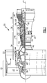
- FIG. 1 schematically illustrates an example gas turbine engine 20 that includes a fan section 22, a compressor section 24, a combustor section 26 and a turbine section 28.
- Alternative engines might include an augmenter section (not shown) among other systems or features.
- the fan section 22 drives air along a bypass flow path B while the compressor section 24 draws air in along a core flow path C where air is compressed and communicated to a combustor section 26.
- air is mixed with fuel and ignited to generate a high pressure exhaust gas stream that expands through the turbine section 28 where energy is extracted and utilized to drive the fan section 22 and the compressor section 24.
- turbofan gas turbine engine depicts a turbofan gas turbine engine
- the concepts described herein are not limited to use with turbofans as the teachings may be applied to other types of turbine engines; for example a turbine engine including a three-spool architecture in which three spools concentrically rotate about a common axis and where a low spool enables a low pressure turbine to drive a fan via a gearbox, an intermediate spool that enables an intermediate pressure turbine to drive a first compressor of the compressor section, and a high spool that enables a high pressure turbine to drive a high pressure compressor of the compressor section.
- the example engine 20 generally includes a low speed spool 30 and a high speed spool 32 mounted for rotation about an engine central longitudinal axis A relative to an engine static structure 36 via several bearing systems 38. It should be understood that various bearing systems 38 at various locations may alternatively or additionally be provided.
- the low speed spool 30 generally includes an inner shaft 40 that connects a fan 42 and a low pressure (or first) compressor section 44 to a low pressure (or first) turbine section 46.
- the inner shaft 40 drives the fan 42 through a speed change device, such as a geared architecture 48, to drive the fan 42 at a lower speed than the low speed spool 30.
- the high-speed spool 32 includes an outer shaft 50 that interconnects a high pressure (or second) compressor section 52 and a high pressure (or second) turbine section 54.
- the inner shaft 40 and the outer shaft 50 are concentric and rotate via the bearing systems 38 about the engine central longitudinal axis A.
- a combustor 56 is arranged between the high pressure compressor 52 and the high pressure turbine 54.
- the high pressure turbine 54 includes at least two stages to provide a double stage high pressure turbine 54.
- the high pressure turbine 54 includes only a single stage.
- a "high pressure" compressor or turbine experiences a higher pressure than a corresponding "low pressure” compressor or turbine.
- the example low pressure turbine 46 has a pressure ratio that is greater than about 5.
- the pressure ratio of the example low pressure turbine 46 is measured prior to an inlet of the low pressure turbine 46 as related to the pressure measured at the outlet of the low pressure turbine 46 prior to an exhaust nozzle.
- a mid-turbine frame assembly 58 of the engine static structure 36 is arranged generally between the high pressure turbine 54 and the low pressure turbine 46.
- the mid-turbine frame assembly 58 further supports bearing systems 38 in the turbine section 28 as well as setting airflow entering the low pressure turbine 46.
- Airflow through the core airflow path C is compressed by the low pressure compressor 44 then by the high pressure compressor 52 mixed with fuel and ignited in the combustor 56 to produce high speed exhaust gases that are then expanded through the high pressure turbine 54 and low pressure turbine 46.
- the mid-turbine frame assembly 58 includes vanes 60, which are in the core airflow path C and function as an inlet guide vane for the low pressure turbine 46. Temperatures of the exhaust gases are such that cooling of the mid-turbine frame assembly 58 may be required.
- a low temperature cooling air flow (LTCA) supply tube 66 communicates relatively cool air from the compressor section 24 to the turbine section 28. In this example, the supply tube 66 communicates relatively low temperature cooling air 18 from one of the initial stages of the high pressure compressor 52 to the mid-turbine frame assembly 58.
- LTCA low temperature cooling air flow
- the disclosed gas turbine engine 20 in one example is a high-bypass geared aircraft engine.
- the gas turbine engine 20 includes a bypass ratio greater than about six (6), with an example embodiment being greater than about ten (10).
- the example geared architecture 48 is an epicyclical gear train, such as a planetary gear system, star gear system or other known gear system, with a gear reduction ratio of greater than about 2.3.
- the gas turbine engine 20 includes a bypass ratio greater than about ten (10:1) and the fan diameter is significantly larger than an outer diameter of the low pressure compressor 44. It should be understood, however, that the above parameters are only exemplary of one embodiment of a gas turbine engine including a geared architecture and that the present disclosure is applicable to other gas turbine engines.
- the fan section 22 of the engine 20 is designed for a particular flight condition -- typically cruise at about 0.8 Mach and about 35,000 feet (10.67km).
- the flight condition of 0.8 Mach and 35,000 ft (10.67km), with the engine at its best fuel consumption - also known as "bucket cruise Thrust Specific Fuel Consumption ('TSFC')" - is the industry standard parameter of pound-mass of fuel per hour being burned divided by pound-force of thrust the engine produces at that minimum point.
- Low fan pressure ratio is the pressure ratio across the fan blade alone, without a Fan Exit Guide Vane (“FEGV”) system.
- the low fan pressure ratio as disclosed herein according to one non-limiting embodiment is less than about 1.50. In another non-limiting embodiment the low fan pressure ratio is less than about 1.45.
- the "Low corrected fan tip speed”, as disclosed herein according to one non-limiting embodiment, is less than about 1150 ft/second (350 meters/second).
- the example gas turbine engine includes the fan 42 that comprises in one non-limiting embodiment less than about 26 fan blades. In another non-limiting embodiment, the fan section 22 includes less than about twenty (20) fan blades. Moreover, in one disclosed embodiment the low pressure turbine 46 includes no more than about six (6) turbine rotors schematically indicated at 34. In another non-limiting example embodiment the low pressure turbine 46 includes about three (3) turbine rotors. A ratio between the number of fan blades 42 and the number of low pressure turbine rotors is between about 3.3 and about 8.6. The example low pressure turbine 46 provides the driving power to rotate the fan section 22 and therefore the relationship between the number of turbine rotors 34 in the low pressure turbine 46 and the number of blades 42 in the fan section 22 disclose an example gas turbine engine 20 with increased power transfer efficiency.
- an example mid-turbine frame assembly 58 includes an outer cavity 62 and an inner cavity 64.
- the outer cavity 62 is disposed radially outward of the airfoils 60 and the inner cavity 64 is disposed radially inward of the airfoils 60.
- Several LTCA supply pipes 66 deliver cooling air from the compressor section 24 to the outer cavity 62.
- four (4) supply tubes 66 are arranged ninety (90) degrees apart about the circumference of the mid-turbine vane assembly 58.
- different numbers of supply tubes 66 could be utilized in different locations about the mid-turbine vane assembly 58.
- cooling air 18 is extracted from an initial stage of the high pressure compressor 52.
- cooling air may be obtained from other portions of the engine 20 that include air at appropriate pressures and temperatures.
- the mid-turbine frame assembly 58 includes a plurality of airfoils 60 and vane struts 76 arranged circumferentially about the engine axis A.
- the airfoils 60 define passages between the high pressure turbine 54 and the low pressure turbine 46.
- the vane struts 76 provide support for structures such as bearings supported radially inward of the airfoils 60.
- the outer cavity 62 and inner cavity 64 are provided with cooling air 18 that is circulated from the outer cavity 62 to the inner cavity 64 through openings between the airfoils 60 and vane struts 76.
- the outer cavity 62 is defined between a radially outer wall 80 and a radially inner wall 78.
- the radially inner wall 78 is exposed to high temperature gas flow 82 and it therefore operates at a substantially higher temperature than the radially outer wall 80.
- Cooling air 18 is communicated to the outer cavity 62 to cool the mid-turbine frame 58.
- the cooling air 18 is also communicated through the outer cavity 62 to a low pressure turbine (LPT) cavity 86 defined within a turbine case 74 ( Fig. 3 ) through a plurality of supply holes 72.
- Cooling air 18 may also be communicated to the LPT cavity 86 through a feather seal 72 defined at an aft portion of the outer cavity 62.
- LPT low pressure turbine
- the mid-turbine frame assembly 58 is very hot and therefore the temperature of the cooling air 18 provided to cool the low pressure turbine case 74 may require additional cooling features to provide a flow of a desired temperature determined to provide the desired cooling of the low pressure turbine 46. Cooling air 18 that directly impinges on the radially inner wall 78 is heated and can reach temperatures above desired threshold values for cooling the turbine case 74. Additionally, direct impingement of cooling air onto the inner wall 78 can result in non-uniform temperatures of the inner wall 78 that can increase thermal stresses.
- the example mid-turbine frame assembly 58 includes features that prevent direct impingement and provide a more uniform temperature distribution within the inner wall 78.
- the supply pipe 66 communicates cooling air flow 18 to a baffle 68.
- the baffle 68 is disposed within the outer cavity 62 and includes a plurality of openings 86.
- the baffle 68 directs incoming cooling air outward in a direction transverse to the inner radial wall 78 to prevent direct impingement of cooling air on the inner radial wall 78.
- the example baffle 68 receives cooling air flow 18 and distributes the cooling airflow as indicated by arrows 84 forward, aft, and circumferentially within the outer cavity 62 such that the cooling air flow 84 is directed transverse relative to the incoming airflow 18.
- the transverse direction can include components in the forward and aft direction parallel with the axis A and also include a circumferential component within the outer cavity 62.
- the baffle 68 is cylindrical and includes openings disposed about an outer periphery to distribute cooling airflow 84 into the outer cavity 62. It should be understood that although a cylindrical shape is disclosed, the baffle 68 may comprise any shapes desired to direct airflow within the outer cavity 62. Moreover, the openings 86 are holes that provide a desired flow area for the cooling airflow 84. The openings 86 may be holes, slots, or any other shape that provides a desired direction of cooling airflow into the outer cavity 62.
- the openings 86 combine to provide a desired flow area for the cooling airflow 84.
- the flow area provided by the plurality of openings 86 can be tailored to provide a desired metering of cooling airflow as is desired for cooling of both the mid-turbine frame and the turbine case 74.
- the directed airflow 84 does not directly impinge on the inner radial wall 78 and therefore does not become heated above desired threshold limits. Moreover, the baffle directs cooling airflow 84 to provide a substantially uniform temperature of the radially inner wall 78. The reduction in heating of the cooling airflow 84 within the outer cavity 64 provides a uniform flow of cooling air into through the openings 72 into the cavity 88 of the turbine case 74.
- the disclosed baffle 68 prevents impingement of cooling airflow on the radially inner wall 78 of the cavity 62 to generate a more uniform temperature. Additionally, the baffle 68 directs cooling air transverse to the radially inner wall 78 such that cooling air within the cavity 62 may be maintained at a lower temperature within a desired threshold temperature range for cooling of a turbine case 74.
- the example mid-turbine frame 58 includes baffles 68 at each inlet for cooling airflow 18 ( Figure 7 ) such that airflow is directed circumferentially about the axis A.
- inlets 66 are spaced evenly apart about the axis A and provide cooling air to a corresponding baffle 68.
- the baffle 68 distributes the cooling airflow 84 transverse to incoming airflow 18 and to the inner radial wall 78 to prevent absorption of excessive heat in any one location.
- the distribution provided by the baffles 68 generate a more uniform temperature distribution in both the radial wall 78 and the cooling air 84 circulating though the outer cavity 62.
Description
- A gas turbine engine typically includes a fan section, a compressor section, a combustor section and a turbine section. Air entering the compressor section is compressed and delivered into the combustion section where it is mixed with fuel and ignited to generate a high-speed exhaust gas flow. The high-speed exhaust gas flow expands through the turbine section to drive the compressor and the fan section. The compressor section typically includes low and high pressure compressors, and the turbine section includes low and high pressure turbines.
- A mid-turbine frame is sometimes provided between the high pressure turbine and the low pressure turbine to aid in supporting bearing assemblies. The low pressure turbine case requires cooling air to maintain temperatures within a desired limit. Cooling air is extracted from the compressor section and routed to a cavity within the mid-turbine frame. Cooling air from the cavity within the mid-turbine frame is then routed to cool the low pressure turbine case. In some applications, the mid-turbine frame is at a temperature such that cooling air within the cavity is heated above a temperature capable of sufficiently cooling the low pressure turbine case.
-
EP 2573329 A describes air system architecture for a mid-turbine frame module. -
EP 2264282 A2 describes a cooled gas turbine stator assembly. -
EP 1526251 A1 describes a turbine nozzle cooling configuration. - Accordingly, it is desirable to design and develop cooling features and systems for maintaining desired temperatures within the turbine case.
- A turbine engine according to the features of claim 1, among other possible things includes a turbine section including a turbine case disposed about an axis. A frame assembly defines an outer cavity. The outer cavity includes radially outer wall, a radially inner wall and at least one opening configured and adapted to communicate cooling air to the turbine case. A baffle is configured to receive cooling air through the radially outer wall and direct cooling airflow within the outer cavity to prevent impingement on the inner wall.
- In an embodiment of the foregoing turbine engine, the baffle includes a plurality of openings for directing cooling air transverse to the radially inner wall of the outer cavity.
- In a further embodiment of any of the foregoing turbine engines, the baffle is disposed within the outer cavity.
- In a further embodiment of any of the foregoing turbine engines, the plurality of openings are disposed about an outer periphery of the baffle for directing cooling airflow forward, aft and circumferentially within the outer cavity.
- In a further embodiment of any of the foregoing turbine engines, the plurality of openings includes holes.
- In a further embodiment of any of the foregoing turbine engines, the plurality of openings includes slots.
- In a further embodiment of any of the foregoing turbine engines, includes a compressor section in communication with a supply tube for supplying cooling air to the baffle.
- In a further embodiment of any of the foregoing turbine engines, the compressor section includes a high pressure compressor.
- In a further embodiment of any of the foregoing turbine engines, the turbine section includes a high pressure turbine and a low pressure turbine and the frame is a mid-turbine frame which defines a flow path between the high pressure turbine and the low pressure turbine. The frame assembly for a turbine engine according to an exemplary embodiment of this disclosure, among other possible things includes a plurality of vane struts extending radially outward relative to an axis, an outer cavity which includes an opening for communicating cooling air to a turbine section of the turbine engine, and a baffle within the outer cavity configured and adapted to receive cooling air. The baffle includes a plurality of openings for directing cooling airflow into the outer cavity for preventing impingement on a radially inner wall of the outer cavity for maintaining a desired temperature of the cooling air within the outer cavity.
- In an embodiment of the foregoing frame assembly, the plurality of openings direct cooling airflow forward, aft and circumferentially within the outer cavity.
- In a further embodiment of any of the foregoing frame assemblies, the plurality of openings includes a plurality of holes.
- In a further embodiment of any of the foregoing frame assemblies, the plurality of openings includes a plurality of slots.
- In a further embodiment of any of the foregoing embodiments, the plurality of openings define an total opening area for metering cooling airflow into the outer cavity.
- In a further embodiment of any of the foregoing embodiments, includes an inner cavity radially inward of the plurality of vane struts. The inner cavity is in communication with the outer cavity.
- In a further embodiment of any of the foregoing embodiments, the opening for communicating cooling air to the turbine section include a plurality of openings disposed circumferentially within the outer cavity.
- In a further embodiment of any of the foregoing embodiments, the baffle includes at least two baffles directing cooling air within the outer cavity.
- Although the different examples have the specific components shown in the illustrations, embodiments of this disclosure are not limited to those particular combinations. It is possible to use some of the components or features from one of the examples in combination with features or components from another one of the examples.
- These and other features disclosed herein can be best understood from the following specification and drawings, the following of which is a brief description.
-
-
Figure 1 is a schematic view of an example gas turbine engine. -
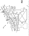
Figure 2 is an axial section view of an example mid-turbine frame assembly. -
Figure 3 is a sectional view of a portion of the example mid-turbine frame assembly. -
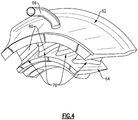
Figure 4 is a perspective view of a portion of an outer cavity of the mid-turbine frame assembly. -
Figure 5 is a schematic view of the outer cavity and example baffle. -
Figure 6 is a top schematic view of the example baffle. -
Figure 7 is a sectional view of cooling airflow within the example mid-turbine frame assembly. -
Figure 1 schematically illustrates an examplegas turbine engine 20 that includes a fan section 22, acompressor section 24, acombustor section 26 and aturbine section 28. Alternative engines might include an augmenter section (not shown) among other systems or features. The fan section 22 drives air along a bypass flow path B while thecompressor section 24 draws air in along a core flow path C where air is compressed and communicated to acombustor section 26. In thecombustor section 26, air is mixed with fuel and ignited to generate a high pressure exhaust gas stream that expands through theturbine section 28 where energy is extracted and utilized to drive the fan section 22 and thecompressor section 24. - Although the disclosed non-limiting embodiment depicts a turbofan gas turbine engine, it should be understood that the concepts described herein are not limited to use with turbofans as the teachings may be applied to other types of turbine engines; for example a turbine engine including a three-spool architecture in which three spools concentrically rotate about a common axis and where a low spool enables a low pressure turbine to drive a fan via a gearbox, an intermediate spool that enables an intermediate pressure turbine to drive a first compressor of the compressor section, and a high spool that enables a high pressure turbine to drive a high pressure compressor of the compressor section.
- The
example engine 20 generally includes alow speed spool 30 and ahigh speed spool 32 mounted for rotation about an engine central longitudinal axis A relative to an enginestatic structure 36 viaseveral bearing systems 38. It should be understood thatvarious bearing systems 38 at various locations may alternatively or additionally be provided. - The
low speed spool 30 generally includes aninner shaft 40 that connects afan 42 and a low pressure (or first) compressor section 44 to a low pressure (or first)turbine section 46. Theinner shaft 40 drives thefan 42 through a speed change device, such as a gearedarchitecture 48, to drive thefan 42 at a lower speed than thelow speed spool 30. The high-speed spool 32 includes anouter shaft 50 that interconnects a high pressure (or second)compressor section 52 and a high pressure (or second)turbine section 54. Theinner shaft 40 and theouter shaft 50 are concentric and rotate via thebearing systems 38 about the engine central longitudinal axis A. - A
combustor 56 is arranged between thehigh pressure compressor 52 and thehigh pressure turbine 54. In one example, thehigh pressure turbine 54 includes at least two stages to provide a double stagehigh pressure turbine 54. In another example, thehigh pressure turbine 54 includes only a single stage. As used herein, a "high pressure" compressor or turbine experiences a higher pressure than a corresponding "low pressure" compressor or turbine. - The example
low pressure turbine 46 has a pressure ratio that is greater than about 5. The pressure ratio of the examplelow pressure turbine 46 is measured prior to an inlet of thelow pressure turbine 46 as related to the pressure measured at the outlet of thelow pressure turbine 46 prior to an exhaust nozzle. - A
mid-turbine frame assembly 58 of the enginestatic structure 36 is arranged generally between thehigh pressure turbine 54 and thelow pressure turbine 46. Themid-turbine frame assembly 58 furthersupports bearing systems 38 in theturbine section 28 as well as setting airflow entering thelow pressure turbine 46. - Airflow through the core airflow path C is compressed by the low pressure compressor 44 then by the
high pressure compressor 52 mixed with fuel and ignited in thecombustor 56 to produce high speed exhaust gases that are then expanded through thehigh pressure turbine 54 andlow pressure turbine 46. - The
mid-turbine frame assembly 58 includesvanes 60, which are in the core airflow path C and function as an inlet guide vane for thelow pressure turbine 46. Temperatures of the exhaust gases are such that cooling of themid-turbine frame assembly 58 may be required. A low temperature cooling air flow (LTCA)supply tube 66 communicates relatively cool air from thecompressor section 24 to theturbine section 28. In this example, thesupply tube 66 communicates relatively lowtemperature cooling air 18 from one of the initial stages of thehigh pressure compressor 52 to themid-turbine frame assembly 58. - Utilizing the
vane 60 of themid-turbine frame assembly 58 as the inlet guide vane forlow pressure turbine 46 decreases the length of thelow pressure turbine 46 without increasing the axial length of themid-turbine frame assembly 58. Reducing or eliminating the number of vanes in thelow pressure turbine 46 shortens the axial length of theturbine section 28. Thus, the compactness of thegas turbine engine 20 is increased and a higher power density may be achieved. - The disclosed
gas turbine engine 20 in one example is a high-bypass geared aircraft engine. In a further example, thegas turbine engine 20 includes a bypass ratio greater than about six (6), with an example embodiment being greater than about ten (10). The example gearedarchitecture 48 is an epicyclical gear train, such as a planetary gear system, star gear system or other known gear system, with a gear reduction ratio of greater than about 2.3. - In one disclosed embodiment, the
gas turbine engine 20 includes a bypass ratio greater than about ten (10:1) and the fan diameter is significantly larger than an outer diameter of the low pressure compressor 44. It should be understood, however, that the above parameters are only exemplary of one embodiment of a gas turbine engine including a geared architecture and that the present disclosure is applicable to other gas turbine engines. - A significant amount of thrust is provided by airflow through the bypass flow path B due to the high bypass ratio. The fan section 22 of the
engine 20 is designed for a particular flight condition -- typically cruise at about 0.8 Mach and about 35,000 feet (10.67km). The flight condition of 0.8 Mach and 35,000 ft (10.67km), with the engine at its best fuel consumption - also known as "bucket cruise Thrust Specific Fuel Consumption ('TSFC')" - is the industry standard parameter of pound-mass of fuel per hour being burned divided by pound-force of thrust the engine produces at that minimum point. - "Low fan pressure ratio" is the pressure ratio across the fan blade alone, without a Fan Exit Guide Vane ("FEGV") system. The low fan pressure ratio as disclosed herein according to one non-limiting embodiment is less than about 1.50. In another non-limiting embodiment the low fan pressure ratio is less than about 1.45.
- "Low corrected fan tip speed" is the actual fan tip speed divided by an industry standard temperature correction of [(Tram °R)/(518.7°R)]0.5 where I°R = 0.556 K (Kelvin). The "Low corrected fan tip speed", as disclosed herein according to one non-limiting embodiment, is less than about 1150 ft/second (350 meters/second).
- The example gas turbine engine includes the
fan 42 that comprises in one non-limiting embodiment less than about 26 fan blades. In another non-limiting embodiment, the fan section 22 includes less than about twenty (20) fan blades. Moreover, in one disclosed embodiment thelow pressure turbine 46 includes no more than about six (6) turbine rotors schematically indicated at 34. In another non-limiting example embodiment thelow pressure turbine 46 includes about three (3) turbine rotors. A ratio between the number offan blades 42 and the number of low pressure turbine rotors is between about 3.3 and about 8.6. The examplelow pressure turbine 46 provides the driving power to rotate the fan section 22 and therefore the relationship between the number ofturbine rotors 34 in thelow pressure turbine 46 and the number ofblades 42 in the fan section 22 disclose an examplegas turbine engine 20 with increased power transfer efficiency. - Referring to
Figures 2 ,3 and4 an examplemid-turbine frame assembly 58 includes anouter cavity 62 and aninner cavity 64. Theouter cavity 62 is disposed radially outward of theairfoils 60 and theinner cavity 64 is disposed radially inward of theairfoils 60. SeveralLTCA supply pipes 66 deliver cooling air from thecompressor section 24 to theouter cavity 62. In this example, four (4)supply tubes 66 are arranged ninety (90) degrees apart about the circumference of themid-turbine vane assembly 58. As appreciated, different numbers ofsupply tubes 66 could be utilized in different locations about themid-turbine vane assembly 58. In this example, coolingair 18 is extracted from an initial stage of thehigh pressure compressor 52. As appreciated, cooling air may be obtained from other portions of theengine 20 that include air at appropriate pressures and temperatures. - The
mid-turbine frame assembly 58 includes a plurality ofairfoils 60 and vane struts 76 arranged circumferentially about the engine axis A. Theairfoils 60 define passages between thehigh pressure turbine 54 and thelow pressure turbine 46. The vane struts 76 provide support for structures such as bearings supported radially inward of theairfoils 60. Theouter cavity 62 andinner cavity 64 are provided with coolingair 18 that is circulated from theouter cavity 62 to theinner cavity 64 through openings between theairfoils 60 and vane struts 76. - The
outer cavity 62 is defined between a radiallyouter wall 80 and a radiallyinner wall 78. The radiallyinner wall 78 is exposed to hightemperature gas flow 82 and it therefore operates at a substantially higher temperature than the radiallyouter wall 80. - Cooling
air 18 is communicated to theouter cavity 62 to cool themid-turbine frame 58. The coolingair 18 is also communicated through theouter cavity 62 to a low pressure turbine (LPT)cavity 86 defined within a turbine case 74 (Fig. 3 ) through a plurality of supply holes 72. Coolingair 18 may also be communicated to theLPT cavity 86 through afeather seal 72 defined at an aft portion of theouter cavity 62. - The
mid-turbine frame assembly 58 is very hot and therefore the temperature of the coolingair 18 provided to cool the lowpressure turbine case 74 may require additional cooling features to provide a flow of a desired temperature determined to provide the desired cooling of thelow pressure turbine 46. Coolingair 18 that directly impinges on the radiallyinner wall 78 is heated and can reach temperatures above desired threshold values for cooling theturbine case 74. Additionally, direct impingement of cooling air onto theinner wall 78 can result in non-uniform temperatures of theinner wall 78 that can increase thermal stresses. - Accordingly, the example
mid-turbine frame assembly 58 includes features that prevent direct impingement and provide a more uniform temperature distribution within theinner wall 78. - Referring to
Figures 5, 6 , and7 , thesupply pipe 66, communicates coolingair flow 18 to abaffle 68. Thebaffle 68 is disposed within theouter cavity 62 and includes a plurality ofopenings 86. In the disclosed example, thebaffle 68 directs incoming cooling air outward in a direction transverse to the innerradial wall 78 to prevent direct impingement of cooling air on the innerradial wall 78. - The
example baffle 68 receives coolingair flow 18 and distributes the cooling airflow as indicated byarrows 84 forward, aft, and circumferentially within theouter cavity 62 such that the coolingair flow 84 is directed transverse relative to theincoming airflow 18. The transverse direction can include components in the forward and aft direction parallel with the axis A and also include a circumferential component within theouter cavity 62. - In this example, the
baffle 68 is cylindrical and includes openings disposed about an outer periphery to distributecooling airflow 84 into theouter cavity 62. It should be understood that although a cylindrical shape is disclosed, thebaffle 68 may comprise any shapes desired to direct airflow within theouter cavity 62. Moreover, theopenings 86 are holes that provide a desired flow area for the coolingairflow 84. Theopenings 86 may be holes, slots, or any other shape that provides a desired direction of cooling airflow into theouter cavity 62. - The
openings 86 combine to provide a desired flow area for the coolingairflow 84. The flow area provided by the plurality ofopenings 86 can be tailored to provide a desired metering of cooling airflow as is desired for cooling of both the mid-turbine frame and theturbine case 74. - The directed
airflow 84 does not directly impinge on the innerradial wall 78 and therefore does not become heated above desired threshold limits. Moreover, the baffle directs coolingairflow 84 to provide a substantially uniform temperature of the radiallyinner wall 78. The reduction in heating of the coolingairflow 84 within theouter cavity 64 provides a uniform flow of cooling air into through theopenings 72 into thecavity 88 of theturbine case 74. - Accordingly, the disclosed
baffle 68 prevents impingement of cooling airflow on the radiallyinner wall 78 of thecavity 62 to generate a more uniform temperature. Additionally, thebaffle 68 directs cooling air transverse to the radiallyinner wall 78 such that cooling air within thecavity 62 may be maintained at a lower temperature within a desired threshold temperature range for cooling of aturbine case 74. - The
example mid-turbine frame 58 includesbaffles 68 at each inlet for cooling airflow 18 (Figure 7 ) such that airflow is directed circumferentially about the axis A. In this example,inlets 66 are spaced evenly apart about the axis A and provide cooling air to acorresponding baffle 68. Thebaffle 68 distributes the coolingairflow 84 transverse toincoming airflow 18 and to the innerradial wall 78 to prevent absorption of excessive heat in any one location. The distribution provided by thebaffles 68 generate a more uniform temperature distribution in both theradial wall 78 and the coolingair 84 circulating though theouter cavity 62. - Although an example embodiment has been disclosed, a worker of ordinary skill in this art would recognize that certain modifications would come within the scope of this disclosure. For that reason, the following claims should be studied to determine the scope and content of this disclosure.
Claims (13)
- A turbine engine (20), comprising:a turbine section (28) including a turbine case (74) disposed about an axis;a frame assembly (58) defining an outer cavity (62), wherein the outer cavity (62) includes radially outer wall (80), a radially inner wall (78) and at least one baffle (68) extending into the outer cavity (62) and spaced from the radially outer wall (80), the baffle (68) separate from the radially outer wall (80); and characterized bysaid baffle (68) being configured to receive cooling air through the radially outer wall (80) and direct cooling airflow outward in a plurality of directions transverse to the radially inner wall (78) within the outer cavity (62) to prevent impingement on the inner wall (78).
- The turbine engine as recited in claim 1, wherein the baffle (68) includes a plurality of openings (86) for directing cooling air transverse to the radially inner wall (78) of the outer cavity (62).
- The turbine engine as recited in claim 2, wherein the baffle (68) is disposed within the outer cavity (62).
- The turbine engine as recited in claim 3, wherein the plurality of openings (86) are disposed about an outer periphery of the baffle (68) for directing cooling airflow forward, aft and circumferentially within the outer cavity (62).
- The turbine engine as recited in claim 2, 3 or 4, wherein the plurality of openings (86) comprises holes.
- The turbine engine as recited in any of claims 2 to 5, wherein the plurality of openings (86) comprises slots.
- The turbine engine as recited in any preceding claim, including a compressor section (24) in communication with a supply tube (66) for supplying cooling air to the baffle (68), wherein the compressor section optionally comprises a high pressure compressor (52).
- The turbine engine as recited in any preceding claim, wherein the turbine section (28) includes a high pressure turbine (54) and a low pressure turbine (46) and the frame is a mid-turbine frame (58) which defines a flow path between the high pressure turbine (54) and the low pressure turbine (46).
- The gas turbine engine of claim 1, wherein the frame assembly (58) comprises:a plurality of airfoils (60) and a corresponding plurality of vane struts (76) extending radially outward relative to an axis between the outer cavity (62) and the inner cavity (64).
- The turbine engine as recited in any preceding claim, wherein the plurality of openings (86) define a total opening area for metering cooling airflow into the outer cavity (62).
- The turbine engine as recited in any preceding claim, including an inner cavity (64) radially inward of the or a plurality of vane struts (76), wherein the inner cavity (64) is in communication with the outer cavity (62).
- The turbine engine as recited in any preceding claim, wherein the opening for communicating cooling air to the turbine section comprises a plurality of openings disposed circumferentially within the outer cavity (62).
- The turbine engine as recited in any preceding claim, wherein the baffle (68) comprises at least two baffles (68) directing cooling air within the outer cavity (62).
Applications Claiming Priority (1)
| Application Number | Priority Date | Filing Date | Title |
|---|---|---|---|
| US201461939950P | 2014-02-14 | 2014-02-14 |
Publications (2)
| Publication Number | Publication Date |
|---|---|
| EP2907978A1 EP2907978A1 (en) | 2015-08-19 |
| EP2907978B1 true EP2907978B1 (en) | 2017-11-22 |
Family
ID=52633055
Family Applications (1)
| Application Number | Title | Priority Date | Filing Date |
|---|---|---|---|
| EP15154920.1A Active EP2907978B1 (en) | 2014-02-14 | 2015-02-12 | Engine mid-turbine frame having distributive coolant flow |
Country Status (2)
| Country | Link |
|---|---|
| US (1) | US9803501B2 (en) |
| EP (1) | EP2907978B1 (en) |
Cited By (1)
| Publication number | Priority date | Publication date | Assignee | Title |
|---|---|---|---|---|
| EP4105467A1 (en) * | 2021-06-17 | 2022-12-21 | Pratt & Whitney Canada Corp. | Mid-turbine frame with intermediary plenum |
Families Citing this family (14)
| Publication number | Priority date | Publication date | Assignee | Title |
|---|---|---|---|---|
| CN106460550B (en) * | 2014-06-10 | 2018-04-06 | 西门子能源公司 | There is the gas-turbine unit of cooling system in rotor pair in exhaust diffuser |
| US20160146052A1 (en) * | 2014-11-25 | 2016-05-26 | United Technologies Corporation | Forged cast forged outer case for a gas turbine engine |
| WO2017015746A1 (en) | 2015-07-24 | 2017-02-02 | Pratt & Whitney Canada Corp. | Mid-turbine frame spoke cooling system and method |
| US10247035B2 (en) | 2015-07-24 | 2019-04-02 | Pratt & Whitney Canada Corp. | Spoke locking architecture |
| US10443449B2 (en) | 2015-07-24 | 2019-10-15 | Pratt & Whitney Canada Corp. | Spoke mounting arrangement |
| US10975721B2 (en) | 2016-01-12 | 2021-04-13 | Pratt & Whitney Canada Corp. | Cooled containment case using internal plenum |
| EP3342991B1 (en) * | 2016-12-30 | 2020-10-14 | Ansaldo Energia IP UK Limited | Baffles for cooling in a gas turbine |
| US10428676B2 (en) * | 2017-06-13 | 2019-10-01 | Rolls-Royce Corporation | Tip clearance control with variable speed blower |
| US10619492B2 (en) * | 2017-12-11 | 2020-04-14 | United Technologies Corporation | Vane air inlet with fillet |
| US11549396B2 (en) | 2019-11-12 | 2023-01-10 | Pratt & Whitney Canada Corp. | Mid-turbine frame for gas turbine engine |
| US11698005B2 (en) | 2020-02-07 | 2023-07-11 | Raytheon Technologies Corporation | Flow diverter for mid-turbine frame cooling air delivery |
| CN114198153A (en) * | 2020-09-17 | 2022-03-18 | 中国航发商用航空发动机有限责任公司 | Turbine blade cooling system and aircraft engine |
| US20220316352A1 (en) * | 2021-03-31 | 2022-10-06 | Raytheon Technologies Corporation | Flow diverter for mid-turbine frame cooling air delivery |
| US11473439B1 (en) | 2021-09-23 | 2022-10-18 | General Electric Company | Gas turbine engine with hollow rotor in fluid communication with a balance piston cavity |
Family Cites Families (17)
| Publication number | Priority date | Publication date | Assignee | Title |
|---|---|---|---|---|
| US4321007A (en) | 1979-12-21 | 1982-03-23 | United Technologies Corporation | Outer case cooling for a turbine intermediate case |
| US5165847A (en) * | 1991-05-20 | 1992-11-24 | General Electric Company | Tapered enlargement metering inlet channel for a shroud cooling assembly of gas turbine engines |
| US5160241A (en) * | 1991-09-09 | 1992-11-03 | General Electric Company | Multi-port air channeling assembly |
| US5292227A (en) | 1992-12-10 | 1994-03-08 | General Electric Company | Turbine frame |
| US5630703A (en) | 1995-12-15 | 1997-05-20 | General Electric Company | Rotor disk post cooling system |
| US6719524B2 (en) * | 2002-02-25 | 2004-04-13 | Honeywell International Inc. | Method of forming a thermally isolated gas turbine engine housing |
| US6929445B2 (en) | 2003-10-22 | 2005-08-16 | General Electric Company | Split flow turbine nozzle |
| US7604453B2 (en) * | 2006-11-30 | 2009-10-20 | General Electric Company | Methods and system for recuperated circumferential cooling of integral turbine nozzle and shroud assemblies |
| US8100633B2 (en) * | 2008-03-11 | 2012-01-24 | United Technologies Corp. | Cooling air manifold splash plates and gas turbines engine systems involving such splash plates |
| US8240974B2 (en) * | 2008-03-21 | 2012-08-14 | United Technologies Corporation | Cold air buffer supply tube |
| US8245518B2 (en) | 2008-11-28 | 2012-08-21 | Pratt & Whitney Canada Corp. | Mid turbine frame system for gas turbine engine |
| US20100303610A1 (en) | 2009-05-29 | 2010-12-02 | United Technologies Corporation | Cooled gas turbine stator assembly |
| US8371127B2 (en) | 2009-10-01 | 2013-02-12 | Pratt & Whitney Canada Corp. | Cooling air system for mid turbine frame |
| US9279341B2 (en) | 2011-09-22 | 2016-03-08 | Pratt & Whitney Canada Corp. | Air system architecture for a mid-turbine frame module |
| US20130149107A1 (en) * | 2011-12-08 | 2013-06-13 | Mrinal Munshi | Gas turbine outer case active ambient cooling including air exhaust into a sub-ambient region of exhaust flow |
| US8366382B1 (en) | 2012-01-31 | 2013-02-05 | United Technologies Corporation | Mid-turbine frame buffer system |
| EP2971612B1 (en) | 2013-03-13 | 2018-01-31 | United Technologies Corporation | Engine mid-turbine frame transfer tube for low pressure turbine case cooling |
-
2015
- 2015-01-28 US US14/607,102 patent/US9803501B2/en active Active
- 2015-02-12 EP EP15154920.1A patent/EP2907978B1/en active Active
Non-Patent Citations (1)
| Title |
|---|
| None * |
Cited By (1)
| Publication number | Priority date | Publication date | Assignee | Title |
|---|---|---|---|---|
| EP4105467A1 (en) * | 2021-06-17 | 2022-12-21 | Pratt & Whitney Canada Corp. | Mid-turbine frame with intermediary plenum |
Also Published As
| Publication number | Publication date |
|---|---|
| EP2907978A1 (en) | 2015-08-19 |
| US9803501B2 (en) | 2017-10-31 |
| US20160245114A1 (en) | 2016-08-25 |
Similar Documents
| Publication | Publication Date | Title |
|---|---|---|
| EP2907978B1 (en) | Engine mid-turbine frame having distributive coolant flow | |
| EP2971612B1 (en) | Engine mid-turbine frame transfer tube for low pressure turbine case cooling | |
| EP2961942B1 (en) | Method and apparatus for handling pre-diffuser airflow for cooling gas turbine components | |
| EP3090163B1 (en) | Compressor rim thermal management | |
| EP2977555B1 (en) | Airfoil platform with cooling channels | |
| EP3039264B1 (en) | Gas turbine engine diffuser cooling and mixing arrangement | |
| EP2901082B1 (en) | Inner diffuser case struts for a combustor of a gas turbine engine | |
| EP2900998B1 (en) | Buffer airflow to bearing compartment | |
| US20140075947A1 (en) | Gas turbine engine component cooling circuit | |
| US10465542B2 (en) | Gas turbine engine turbine vane baffle and serpentine cooling passage | |
| US20190226344A1 (en) | Hybrid cooling schemes for airfoils of gas turbine engines | |
| EP3412868B1 (en) | Vane with adjustable flow split platform cooling for gas turbine engine | |
| US20160312654A1 (en) | Turbine airfoil cooling | |
| EP2977557B1 (en) | Cooled airfoil structure and corresponding cooling method | |
| US11815022B2 (en) | Platform serpentine re-supply | |
| EP3569819B1 (en) | Multiple source impingement baffles for gas turbine engine components | |
| US10655496B2 (en) | Platform flow turning elements for gas turbine engine components | |
| EP3312383B1 (en) | Air mixing systems having mixing chambers for gas turbine engines |
Legal Events
| Date | Code | Title | Description |
|---|---|---|---|
| PUAI | Public reference made under article 153(3) epc to a published international application that has entered the european phase |
Free format text: ORIGINAL CODE: 0009012 |
|
| AK | Designated contracting states |
Kind code of ref document: A1 Designated state(s): AL AT BE BG CH CY CZ DE DK EE ES FI FR GB GR HR HU IE IS IT LI LT LU LV MC MK MT NL NO PL PT RO RS SE SI SK SM TR |
|
| AX | Request for extension of the european patent |
Extension state: BA ME |
|
| 17P | Request for examination filed |
Effective date: 20160218 |
|
| RBV | Designated contracting states (corrected) |
Designated state(s): AL AT BE BG CH CY CZ DE DK EE ES FI FR GB GR HR HU IE IS IT LI LT LU LV MC MK MT NL NO PL PT RO RS SE SI SK SM TR |
|
| RAP1 | Party data changed (applicant data changed or rights of an application transferred) |
Owner name: UNITED TECHNOLOGIES CORPORATION |
|
| 17Q | First examination report despatched |
Effective date: 20161125 |
|
| REG | Reference to a national code |
Ref country code: DE Ref legal event code: R079 Ref document number: 602015006090 Country of ref document: DE Free format text: PREVIOUS MAIN CLASS: F01D0025160000 Ipc: F02C0007180000 |
|
| RIC1 | Information provided on ipc code assigned before grant |
Ipc: F01D 9/04 20060101ALI20170420BHEP Ipc: F01D 25/12 20060101ALI20170420BHEP Ipc: F01D 25/14 20060101ALI20170420BHEP Ipc: F01D 25/16 20060101ALI20170420BHEP Ipc: F02C 7/18 20060101AFI20170420BHEP |
|
| GRAP | Despatch of communication of intention to grant a patent |
Free format text: ORIGINAL CODE: EPIDOSNIGR1 |
|
| INTG | Intention to grant announced |
Effective date: 20170606 |
|
| GRAS | Grant fee paid |
Free format text: ORIGINAL CODE: EPIDOSNIGR3 |
|
| GRAA | (expected) grant |
Free format text: ORIGINAL CODE: 0009210 |
|
| AK | Designated contracting states |
Kind code of ref document: B1 Designated state(s): AL AT BE BG CH CY CZ DE DK EE ES FI FR GB GR HR HU IE IS IT LI LT LU LV MC MK MT NL NO PL PT RO RS SE SI SK SM TR |
|
| REG | Reference to a national code |
Ref country code: GB Ref legal event code: FG4D |
|
| REG | Reference to a national code |
Ref country code: CH Ref legal event code: EP |
|
| REG | Reference to a national code |
Ref country code: IE Ref legal event code: FG4D |
|
| REG | Reference to a national code |
Ref country code: AT Ref legal event code: REF Ref document number: 948632 Country of ref document: AT Kind code of ref document: T Effective date: 20171215 |
|
| REG | Reference to a national code |
Ref country code: DE Ref legal event code: R096 Ref document number: 602015006090 Country of ref document: DE |
|
| REG | Reference to a national code |
Ref country code: FR Ref legal event code: PLFP Year of fee payment: 4 |
|
| REG | Reference to a national code |
Ref country code: NL Ref legal event code: MP Effective date: 20171122 |
|
| REG | Reference to a national code |
Ref country code: LT Ref legal event code: MG4D |
|
| REG | Reference to a national code |
Ref country code: AT Ref legal event code: MK05 Ref document number: 948632 Country of ref document: AT Kind code of ref document: T Effective date: 20171122 |
|
| PG25 | Lapsed in a contracting state [announced via postgrant information from national office to epo] |
Ref country code: NL Free format text: LAPSE BECAUSE OF FAILURE TO SUBMIT A TRANSLATION OF THE DESCRIPTION OR TO PAY THE FEE WITHIN THE PRESCRIBED TIME-LIMIT Effective date: 20171122 Ref country code: FI Free format text: LAPSE BECAUSE OF FAILURE TO SUBMIT A TRANSLATION OF THE DESCRIPTION OR TO PAY THE FEE WITHIN THE PRESCRIBED TIME-LIMIT Effective date: 20171122 Ref country code: SE Free format text: LAPSE BECAUSE OF FAILURE TO SUBMIT A TRANSLATION OF THE DESCRIPTION OR TO PAY THE FEE WITHIN THE PRESCRIBED TIME-LIMIT Effective date: 20171122 Ref country code: ES Free format text: LAPSE BECAUSE OF FAILURE TO SUBMIT A TRANSLATION OF THE DESCRIPTION OR TO PAY THE FEE WITHIN THE PRESCRIBED TIME-LIMIT Effective date: 20171122 Ref country code: LT Free format text: LAPSE BECAUSE OF FAILURE TO SUBMIT A TRANSLATION OF THE DESCRIPTION OR TO PAY THE FEE WITHIN THE PRESCRIBED TIME-LIMIT Effective date: 20171122 Ref country code: NO Free format text: LAPSE BECAUSE OF FAILURE TO SUBMIT A TRANSLATION OF THE DESCRIPTION OR TO PAY THE FEE WITHIN THE PRESCRIBED TIME-LIMIT Effective date: 20180222 |
|
| PG25 | Lapsed in a contracting state [announced via postgrant information from national office to epo] |
Ref country code: LV Free format text: LAPSE BECAUSE OF FAILURE TO SUBMIT A TRANSLATION OF THE DESCRIPTION OR TO PAY THE FEE WITHIN THE PRESCRIBED TIME-LIMIT Effective date: 20171122 Ref country code: GR Free format text: LAPSE BECAUSE OF FAILURE TO SUBMIT A TRANSLATION OF THE DESCRIPTION OR TO PAY THE FEE WITHIN THE PRESCRIBED TIME-LIMIT Effective date: 20180223 Ref country code: BG Free format text: LAPSE BECAUSE OF FAILURE TO SUBMIT A TRANSLATION OF THE DESCRIPTION OR TO PAY THE FEE WITHIN THE PRESCRIBED TIME-LIMIT Effective date: 20180222 Ref country code: RS Free format text: LAPSE BECAUSE OF FAILURE TO SUBMIT A TRANSLATION OF THE DESCRIPTION OR TO PAY THE FEE WITHIN THE PRESCRIBED TIME-LIMIT Effective date: 20171122 Ref country code: HR Free format text: LAPSE BECAUSE OF FAILURE TO SUBMIT A TRANSLATION OF THE DESCRIPTION OR TO PAY THE FEE WITHIN THE PRESCRIBED TIME-LIMIT Effective date: 20171122 Ref country code: AT Free format text: LAPSE BECAUSE OF FAILURE TO SUBMIT A TRANSLATION OF THE DESCRIPTION OR TO PAY THE FEE WITHIN THE PRESCRIBED TIME-LIMIT Effective date: 20171122 |
|
| PG25 | Lapsed in a contracting state [announced via postgrant information from national office to epo] |
Ref country code: SK Free format text: LAPSE BECAUSE OF FAILURE TO SUBMIT A TRANSLATION OF THE DESCRIPTION OR TO PAY THE FEE WITHIN THE PRESCRIBED TIME-LIMIT Effective date: 20171122 Ref country code: CZ Free format text: LAPSE BECAUSE OF FAILURE TO SUBMIT A TRANSLATION OF THE DESCRIPTION OR TO PAY THE FEE WITHIN THE PRESCRIBED TIME-LIMIT Effective date: 20171122 Ref country code: EE Free format text: LAPSE BECAUSE OF FAILURE TO SUBMIT A TRANSLATION OF THE DESCRIPTION OR TO PAY THE FEE WITHIN THE PRESCRIBED TIME-LIMIT Effective date: 20171122 Ref country code: CY Free format text: LAPSE BECAUSE OF FAILURE TO SUBMIT A TRANSLATION OF THE DESCRIPTION OR TO PAY THE FEE WITHIN THE PRESCRIBED TIME-LIMIT Effective date: 20171122 Ref country code: DK Free format text: LAPSE BECAUSE OF FAILURE TO SUBMIT A TRANSLATION OF THE DESCRIPTION OR TO PAY THE FEE WITHIN THE PRESCRIBED TIME-LIMIT Effective date: 20171122 |
|
| REG | Reference to a national code |
Ref country code: DE Ref legal event code: R097 Ref document number: 602015006090 Country of ref document: DE |
|
| PG25 | Lapsed in a contracting state [announced via postgrant information from national office to epo] |
Ref country code: SM Free format text: LAPSE BECAUSE OF FAILURE TO SUBMIT A TRANSLATION OF THE DESCRIPTION OR TO PAY THE FEE WITHIN THE PRESCRIBED TIME-LIMIT Effective date: 20171122 Ref country code: IT Free format text: LAPSE BECAUSE OF FAILURE TO SUBMIT A TRANSLATION OF THE DESCRIPTION OR TO PAY THE FEE WITHIN THE PRESCRIBED TIME-LIMIT Effective date: 20171122 Ref country code: RO Free format text: LAPSE BECAUSE OF FAILURE TO SUBMIT A TRANSLATION OF THE DESCRIPTION OR TO PAY THE FEE WITHIN THE PRESCRIBED TIME-LIMIT Effective date: 20171122 Ref country code: PL Free format text: LAPSE BECAUSE OF FAILURE TO SUBMIT A TRANSLATION OF THE DESCRIPTION OR TO PAY THE FEE WITHIN THE PRESCRIBED TIME-LIMIT Effective date: 20171122 |
|
| REG | Reference to a national code |
Ref country code: CH Ref legal event code: PL |
|
| PG25 | Lapsed in a contracting state [announced via postgrant information from national office to epo] |
Ref country code: MC Free format text: LAPSE BECAUSE OF FAILURE TO SUBMIT A TRANSLATION OF THE DESCRIPTION OR TO PAY THE FEE WITHIN THE PRESCRIBED TIME-LIMIT Effective date: 20171122 |
|
| PLBE | No opposition filed within time limit |
Free format text: ORIGINAL CODE: 0009261 |
|
| STAA | Information on the status of an ep patent application or granted ep patent |
Free format text: STATUS: NO OPPOSITION FILED WITHIN TIME LIMIT |
|
| 26N | No opposition filed |
Effective date: 20180823 |
|
| REG | Reference to a national code |
Ref country code: IE Ref legal event code: MM4A |
|
| REG | Reference to a national code |
Ref country code: BE Ref legal event code: MM Effective date: 20180228 |
|
| PG25 | Lapsed in a contracting state [announced via postgrant information from national office to epo] |
Ref country code: SI Free format text: LAPSE BECAUSE OF FAILURE TO SUBMIT A TRANSLATION OF THE DESCRIPTION OR TO PAY THE FEE WITHIN THE PRESCRIBED TIME-LIMIT Effective date: 20171122 Ref country code: LU Free format text: LAPSE BECAUSE OF NON-PAYMENT OF DUE FEES Effective date: 20180212 Ref country code: CH Free format text: LAPSE BECAUSE OF NON-PAYMENT OF DUE FEES Effective date: 20180228 Ref country code: LI Free format text: LAPSE BECAUSE OF NON-PAYMENT OF DUE FEES Effective date: 20180228 |
|
| PG25 | Lapsed in a contracting state [announced via postgrant information from national office to epo] |
Ref country code: IE Free format text: LAPSE BECAUSE OF NON-PAYMENT OF DUE FEES Effective date: 20180212 |
|
| PG25 | Lapsed in a contracting state [announced via postgrant information from national office to epo] |
Ref country code: BE Free format text: LAPSE BECAUSE OF NON-PAYMENT OF DUE FEES Effective date: 20180228 |
|
| PG25 | Lapsed in a contracting state [announced via postgrant information from national office to epo] |
Ref country code: MT Free format text: LAPSE BECAUSE OF NON-PAYMENT OF DUE FEES Effective date: 20180212 |
|
| PG25 | Lapsed in a contracting state [announced via postgrant information from national office to epo] |
Ref country code: TR Free format text: LAPSE BECAUSE OF FAILURE TO SUBMIT A TRANSLATION OF THE DESCRIPTION OR TO PAY THE FEE WITHIN THE PRESCRIBED TIME-LIMIT Effective date: 20171122 |
|
| PG25 | Lapsed in a contracting state [announced via postgrant information from national office to epo] |
Ref country code: PT Free format text: LAPSE BECAUSE OF FAILURE TO SUBMIT A TRANSLATION OF THE DESCRIPTION OR TO PAY THE FEE WITHIN THE PRESCRIBED TIME-LIMIT Effective date: 20171122 |
|
| PG25 | Lapsed in a contracting state [announced via postgrant information from national office to epo] |
Ref country code: MK Free format text: LAPSE BECAUSE OF NON-PAYMENT OF DUE FEES Effective date: 20171122 Ref country code: HU Free format text: LAPSE BECAUSE OF FAILURE TO SUBMIT A TRANSLATION OF THE DESCRIPTION OR TO PAY THE FEE WITHIN THE PRESCRIBED TIME-LIMIT; INVALID AB INITIO Effective date: 20150212 |
|
| PG25 | Lapsed in a contracting state [announced via postgrant information from national office to epo] |
Ref country code: AL Free format text: LAPSE BECAUSE OF FAILURE TO SUBMIT A TRANSLATION OF THE DESCRIPTION OR TO PAY THE FEE WITHIN THE PRESCRIBED TIME-LIMIT Effective date: 20171122 Ref country code: IS Free format text: LAPSE BECAUSE OF FAILURE TO SUBMIT A TRANSLATION OF THE DESCRIPTION OR TO PAY THE FEE WITHIN THE PRESCRIBED TIME-LIMIT Effective date: 20180322 |
|
| REG | Reference to a national code |
Ref country code: DE Ref legal event code: R081 Ref document number: 602015006090 Country of ref document: DE Owner name: RAYTHEON TECHNOLOGIES CORPORATION (N.D.GES.D.S, US Free format text: FORMER OWNER: UNITED TECHNOLOGIES CORPORATION, FARMINGTON, CONN., US |
|
| PGFP | Annual fee paid to national office [announced via postgrant information from national office to epo] |
Ref country code: FR Payment date: 20230119 Year of fee payment: 9 |
|
| PGFP | Annual fee paid to national office [announced via postgrant information from national office to epo] |
Ref country code: GB Payment date: 20230121 Year of fee payment: 9 Ref country code: DE Payment date: 20230119 Year of fee payment: 9 |
|
| P01 | Opt-out of the competence of the unified patent court (upc) registered |
Effective date: 20230520 |