EP2907651B1 - Procédé et dispositif de soudage par induction de pièces en matériaux composites - Google Patents
Procédé et dispositif de soudage par induction de pièces en matériaux composites Download PDFInfo
- Publication number
- EP2907651B1 EP2907651B1 EP15151123.5A EP15151123A EP2907651B1 EP 2907651 B1 EP2907651 B1 EP 2907651B1 EP 15151123 A EP15151123 A EP 15151123A EP 2907651 B1 EP2907651 B1 EP 2907651B1
- Authority
- EP
- European Patent Office
- Prior art keywords
- assembly
- parts
- magnetic field
- temperature
- field
- Prior art date
- Legal status (The legal status is an assumption and is not a legal conclusion. Google has not performed a legal analysis and makes no representation as to the accuracy of the status listed.)
- Not-in-force
Links
- 239000002131 composite material Substances 0.000 title claims description 39
- 238000000034 method Methods 0.000 title claims description 33
- 238000003466 welding Methods 0.000 title claims description 26
- 230000006698 induction Effects 0.000 title claims description 13
- 230000005291 magnetic effect Effects 0.000 claims description 52
- 229920005989 resin Polymers 0.000 claims description 27
- 239000011347 resin Substances 0.000 claims description 27
- 239000006096 absorbing agent Substances 0.000 claims description 23
- 239000003302 ferromagnetic material Substances 0.000 claims description 22
- 230000008569 process Effects 0.000 claims description 20
- 238000010438 heat treatment Methods 0.000 claims description 19
- 239000002245 particle Substances 0.000 claims description 18
- 230000005294 ferromagnetic effect Effects 0.000 claims description 15
- 229920000049 Carbon (fiber) Polymers 0.000 claims description 14
- 239000004917 carbon fiber Substances 0.000 claims description 14
- 230000009466 transformation Effects 0.000 claims description 12
- 238000006073 displacement reaction Methods 0.000 claims description 8
- 238000001816 cooling Methods 0.000 claims description 5
- 230000015572 biosynthetic process Effects 0.000 claims description 4
- 230000006978 adaptation Effects 0.000 claims description 2
- 239000000835 fiber Substances 0.000 description 7
- 239000000463 material Substances 0.000 description 7
- 239000002184 metal Substances 0.000 description 7
- 229910052751 metal Inorganic materials 0.000 description 7
- 230000000694 effects Effects 0.000 description 5
- 230000035699 permeability Effects 0.000 description 5
- OKTJSMMVPCPJKN-UHFFFAOYSA-N Carbon Chemical compound [C] OKTJSMMVPCPJKN-UHFFFAOYSA-N 0.000 description 4
- 229910052799 carbon Inorganic materials 0.000 description 4
- 238000004519 manufacturing process Methods 0.000 description 4
- 239000011159 matrix material Substances 0.000 description 4
- 239000000203 mixture Substances 0.000 description 4
- 230000035945 sensitivity Effects 0.000 description 4
- 238000009826 distribution Methods 0.000 description 3
- 230000001939 inductive effect Effects 0.000 description 3
- 229920000642 polymer Polymers 0.000 description 3
- 229920001169 thermoplastic Polymers 0.000 description 3
- 239000004416 thermosoftening plastic Substances 0.000 description 3
- 239000004696 Poly ether ether ketone Substances 0.000 description 2
- 238000006243 chemical reaction Methods 0.000 description 2
- 238000013461 design Methods 0.000 description 2
- 230000005298 paramagnetic effect Effects 0.000 description 2
- 229920002492 poly(sulfone) Polymers 0.000 description 2
- 229920002530 polyetherether ketone Polymers 0.000 description 2
- 239000000047 product Substances 0.000 description 2
- 238000005096 rolling process Methods 0.000 description 2
- 238000004088 simulation Methods 0.000 description 2
- XEEYBQQBJWHFJM-UHFFFAOYSA-N Iron Chemical compound [Fe] XEEYBQQBJWHFJM-UHFFFAOYSA-N 0.000 description 1
- JUPQTSLXMOCDHR-UHFFFAOYSA-N benzene-1,4-diol;bis(4-fluorophenyl)methanone Chemical compound OC1=CC=C(O)C=C1.C1=CC(F)=CC=C1C(=O)C1=CC=C(F)C=C1 JUPQTSLXMOCDHR-UHFFFAOYSA-N 0.000 description 1
- 230000008859 change Effects 0.000 description 1
- 239000012141 concentrate Substances 0.000 description 1
- 239000004020 conductor Substances 0.000 description 1
- 239000002178 crystalline material Substances 0.000 description 1
- 238000002425 crystallisation Methods 0.000 description 1
- 230000008025 crystallization Effects 0.000 description 1
- 230000008021 deposition Effects 0.000 description 1
- 230000005672 electromagnetic field Effects 0.000 description 1
- 230000002349 favourable effect Effects 0.000 description 1
- 239000012467 final product Substances 0.000 description 1
- 239000012530 fluid Substances 0.000 description 1
- 230000004927 fusion Effects 0.000 description 1
- 238000001033 granulometry Methods 0.000 description 1
- 238000005470 impregnation Methods 0.000 description 1
- 230000005381 magnetic domain Effects 0.000 description 1
- 230000005415 magnetization Effects 0.000 description 1
- 238000002844 melting Methods 0.000 description 1
- 230000008018 melting Effects 0.000 description 1
- 239000005022 packaging material Substances 0.000 description 1
- 239000002907 paramagnetic material Substances 0.000 description 1
- 239000004033 plastic Substances 0.000 description 1
- 239000002952 polymeric resin Substances 0.000 description 1
- 238000006116 polymerization reaction Methods 0.000 description 1
- 238000012545 processing Methods 0.000 description 1
- 230000002787 reinforcement Effects 0.000 description 1
- 230000004044 response Effects 0.000 description 1
- 238000007789 sealing Methods 0.000 description 1
- 238000004781 supercooling Methods 0.000 description 1
- 229920003002 synthetic resin Polymers 0.000 description 1
- 239000012815 thermoplastic material Substances 0.000 description 1
- 229920001187 thermosetting polymer Polymers 0.000 description 1
- 238000013519 translation Methods 0.000 description 1
- XLYOFNOQVPJJNP-UHFFFAOYSA-N water Substances O XLYOFNOQVPJJNP-UHFFFAOYSA-N 0.000 description 1
Images

Classifications
-
- B—PERFORMING OPERATIONS; TRANSPORTING
- B32—LAYERED PRODUCTS
- B32B—LAYERED PRODUCTS, i.e. PRODUCTS BUILT-UP OF STRATA OF FLAT OR NON-FLAT, e.g. CELLULAR OR HONEYCOMB, FORM
- B32B37/00—Methods or apparatus for laminating, e.g. by curing or by ultrasonic bonding
- B32B37/06—Methods or apparatus for laminating, e.g. by curing or by ultrasonic bonding characterised by the heating method
-
- B—PERFORMING OPERATIONS; TRANSPORTING
- B29—WORKING OF PLASTICS; WORKING OF SUBSTANCES IN A PLASTIC STATE IN GENERAL
- B29C—SHAPING OR JOINING OF PLASTICS; SHAPING OF MATERIAL IN A PLASTIC STATE, NOT OTHERWISE PROVIDED FOR; AFTER-TREATMENT OF THE SHAPED PRODUCTS, e.g. REPAIRING
- B29C66/00—General aspects of processes or apparatus for joining preformed parts
- B29C66/90—Measuring or controlling the joining process
- B29C66/91—Measuring or controlling the joining process by measuring or controlling the temperature, the heat or the thermal flux
- B29C66/914—Measuring or controlling the joining process by measuring or controlling the temperature, the heat or the thermal flux by controlling or regulating the temperature, the heat or the thermal flux
- B29C66/9161—Measuring or controlling the joining process by measuring or controlling the temperature, the heat or the thermal flux by controlling or regulating the temperature, the heat or the thermal flux by controlling or regulating the heat or the thermal flux, i.e. the heat flux
- B29C66/91651—Measuring or controlling the joining process by measuring or controlling the temperature, the heat or the thermal flux by controlling or regulating the temperature, the heat or the thermal flux by controlling or regulating the heat or the thermal flux, i.e. the heat flux by controlling or regulating the heat generated by Joule heating or induction heating
-
- B—PERFORMING OPERATIONS; TRANSPORTING
- B29—WORKING OF PLASTICS; WORKING OF SUBSTANCES IN A PLASTIC STATE IN GENERAL
- B29C—SHAPING OR JOINING OF PLASTICS; SHAPING OF MATERIAL IN A PLASTIC STATE, NOT OTHERWISE PROVIDED FOR; AFTER-TREATMENT OF THE SHAPED PRODUCTS, e.g. REPAIRING
- B29C65/00—Joining or sealing of preformed parts, e.g. welding of plastics materials; Apparatus therefor
- B29C65/02—Joining or sealing of preformed parts, e.g. welding of plastics materials; Apparatus therefor by heating, with or without pressure
- B29C65/34—Joining or sealing of preformed parts, e.g. welding of plastics materials; Apparatus therefor by heating, with or without pressure using heated elements which remain in the joint, e.g. "verlorenes Schweisselement"
- B29C65/36—Joining or sealing of preformed parts, e.g. welding of plastics materials; Apparatus therefor by heating, with or without pressure using heated elements which remain in the joint, e.g. "verlorenes Schweisselement" heated by induction
- B29C65/3668—Joining or sealing of preformed parts, e.g. welding of plastics materials; Apparatus therefor by heating, with or without pressure using heated elements which remain in the joint, e.g. "verlorenes Schweisselement" heated by induction characterised by the means for supplying heat to said heated elements which remain in the join, e.g. special induction coils
-
- B—PERFORMING OPERATIONS; TRANSPORTING
- B29—WORKING OF PLASTICS; WORKING OF SUBSTANCES IN A PLASTIC STATE IN GENERAL
- B29C—SHAPING OR JOINING OF PLASTICS; SHAPING OF MATERIAL IN A PLASTIC STATE, NOT OTHERWISE PROVIDED FOR; AFTER-TREATMENT OF THE SHAPED PRODUCTS, e.g. REPAIRING
- B29C66/00—General aspects of processes or apparatus for joining preformed parts
- B29C66/01—General aspects dealing with the joint area or with the area to be joined
- B29C66/05—Particular design of joint configurations
- B29C66/10—Particular design of joint configurations particular design of the joint cross-sections
- B29C66/11—Joint cross-sections comprising a single joint-segment, i.e. one of the parts to be joined comprising a single joint-segment in the joint cross-section
- B29C66/112—Single lapped joints
- B29C66/1122—Single lap to lap joints, i.e. overlap joints
-
- B—PERFORMING OPERATIONS; TRANSPORTING
- B29—WORKING OF PLASTICS; WORKING OF SUBSTANCES IN A PLASTIC STATE IN GENERAL
- B29C—SHAPING OR JOINING OF PLASTICS; SHAPING OF MATERIAL IN A PLASTIC STATE, NOT OTHERWISE PROVIDED FOR; AFTER-TREATMENT OF THE SHAPED PRODUCTS, e.g. REPAIRING
- B29C66/00—General aspects of processes or apparatus for joining preformed parts
- B29C66/40—General aspects of joining substantially flat articles, e.g. plates, sheets or web-like materials; Making flat seams in tubular or hollow articles; Joining single elements to substantially flat surfaces
- B29C66/47—Joining single elements to sheets, plates or other substantially flat surfaces
- B29C66/472—Joining single elements to sheets, plates or other substantially flat surfaces said single elements being substantially flat
-
- B—PERFORMING OPERATIONS; TRANSPORTING
- B29—WORKING OF PLASTICS; WORKING OF SUBSTANCES IN A PLASTIC STATE IN GENERAL
- B29C—SHAPING OR JOINING OF PLASTICS; SHAPING OF MATERIAL IN A PLASTIC STATE, NOT OTHERWISE PROVIDED FOR; AFTER-TREATMENT OF THE SHAPED PRODUCTS, e.g. REPAIRING
- B29C66/00—General aspects of processes or apparatus for joining preformed parts
- B29C66/70—General aspects of processes or apparatus for joining preformed parts characterised by the composition, physical properties or the structure of the material of the parts to be joined; Joining with non-plastics material
- B29C66/72—General aspects of processes or apparatus for joining preformed parts characterised by the composition, physical properties or the structure of the material of the parts to be joined; Joining with non-plastics material characterised by the structure of the material of the parts to be joined
- B29C66/721—Fibre-reinforced materials
- B29C66/7212—Fibre-reinforced materials characterised by the composition of the fibres
-
- B—PERFORMING OPERATIONS; TRANSPORTING
- B29—WORKING OF PLASTICS; WORKING OF SUBSTANCES IN A PLASTIC STATE IN GENERAL
- B29C—SHAPING OR JOINING OF PLASTICS; SHAPING OF MATERIAL IN A PLASTIC STATE, NOT OTHERWISE PROVIDED FOR; AFTER-TREATMENT OF THE SHAPED PRODUCTS, e.g. REPAIRING
- B29C66/00—General aspects of processes or apparatus for joining preformed parts
- B29C66/80—General aspects of machine operations or constructions and parts thereof
- B29C66/81—General aspects of the pressing elements, i.e. the elements applying pressure on the parts to be joined in the area to be joined, e.g. the welding jaws or clamps
- B29C66/816—General aspects of the pressing elements, i.e. the elements applying pressure on the parts to be joined in the area to be joined, e.g. the welding jaws or clamps characterised by the mounting of the pressing elements, e.g. of the welding jaws or clamps
-
- B—PERFORMING OPERATIONS; TRANSPORTING
- B29—WORKING OF PLASTICS; WORKING OF SUBSTANCES IN A PLASTIC STATE IN GENERAL
- B29C—SHAPING OR JOINING OF PLASTICS; SHAPING OF MATERIAL IN A PLASTIC STATE, NOT OTHERWISE PROVIDED FOR; AFTER-TREATMENT OF THE SHAPED PRODUCTS, e.g. REPAIRING
- B29C66/00—General aspects of processes or apparatus for joining preformed parts
- B29C66/90—Measuring or controlling the joining process
- B29C66/91—Measuring or controlling the joining process by measuring or controlling the temperature, the heat or the thermal flux
- B29C66/914—Measuring or controlling the joining process by measuring or controlling the temperature, the heat or the thermal flux by controlling or regulating the temperature, the heat or the thermal flux
- B29C66/9141—Measuring or controlling the joining process by measuring or controlling the temperature, the heat or the thermal flux by controlling or regulating the temperature, the heat or the thermal flux by controlling or regulating the temperature
- B29C66/91411—Measuring or controlling the joining process by measuring or controlling the temperature, the heat or the thermal flux by controlling or regulating the temperature, the heat or the thermal flux by controlling or regulating the temperature of the parts to be joined, e.g. the joining process taking the temperature of the parts to be joined into account
-
- H—ELECTRICITY
- H05—ELECTRIC TECHNIQUES NOT OTHERWISE PROVIDED FOR
- H05B—ELECTRIC HEATING; ELECTRIC LIGHT SOURCES NOT OTHERWISE PROVIDED FOR; CIRCUIT ARRANGEMENTS FOR ELECTRIC LIGHT SOURCES, IN GENERAL
- H05B6/00—Heating by electric, magnetic or electromagnetic fields
- H05B6/02—Induction heating
- H05B6/10—Induction heating apparatus, other than furnaces, for specific applications
- H05B6/105—Induction heating apparatus, other than furnaces, for specific applications using a susceptor
-
- H—ELECTRICITY
- H05—ELECTRIC TECHNIQUES NOT OTHERWISE PROVIDED FOR
- H05B—ELECTRIC HEATING; ELECTRIC LIGHT SOURCES NOT OTHERWISE PROVIDED FOR; CIRCUIT ARRANGEMENTS FOR ELECTRIC LIGHT SOURCES, IN GENERAL
- H05B6/00—Heating by electric, magnetic or electromagnetic fields
- H05B6/02—Induction heating
- H05B6/36—Coil arrangements
- H05B6/40—Establishing desired heat distribution, e.g. to heat particular parts of workpieces
-
- B—PERFORMING OPERATIONS; TRANSPORTING
- B29—WORKING OF PLASTICS; WORKING OF SUBSTANCES IN A PLASTIC STATE IN GENERAL
- B29C—SHAPING OR JOINING OF PLASTICS; SHAPING OF MATERIAL IN A PLASTIC STATE, NOT OTHERWISE PROVIDED FOR; AFTER-TREATMENT OF THE SHAPED PRODUCTS, e.g. REPAIRING
- B29C65/00—Joining or sealing of preformed parts, e.g. welding of plastics materials; Apparatus therefor
- B29C65/02—Joining or sealing of preformed parts, e.g. welding of plastics materials; Apparatus therefor by heating, with or without pressure
- B29C65/34—Joining or sealing of preformed parts, e.g. welding of plastics materials; Apparatus therefor by heating, with or without pressure using heated elements which remain in the joint, e.g. "verlorenes Schweisselement"
- B29C65/36—Joining or sealing of preformed parts, e.g. welding of plastics materials; Apparatus therefor by heating, with or without pressure using heated elements which remain in the joint, e.g. "verlorenes Schweisselement" heated by induction
- B29C65/3604—Joining or sealing of preformed parts, e.g. welding of plastics materials; Apparatus therefor by heating, with or without pressure using heated elements which remain in the joint, e.g. "verlorenes Schweisselement" heated by induction characterised by the type of elements heated by induction which remain in the joint
- B29C65/3608—Joining or sealing of preformed parts, e.g. welding of plastics materials; Apparatus therefor by heating, with or without pressure using heated elements which remain in the joint, e.g. "verlorenes Schweisselement" heated by induction characterised by the type of elements heated by induction which remain in the joint comprising single particles, e.g. fillers or discontinuous fibre-reinforcements
- B29C65/3612—Joining or sealing of preformed parts, e.g. welding of plastics materials; Apparatus therefor by heating, with or without pressure using heated elements which remain in the joint, e.g. "verlorenes Schweisselement" heated by induction characterised by the type of elements heated by induction which remain in the joint comprising single particles, e.g. fillers or discontinuous fibre-reinforcements comprising fillers
-
- B—PERFORMING OPERATIONS; TRANSPORTING
- B29—WORKING OF PLASTICS; WORKING OF SUBSTANCES IN A PLASTIC STATE IN GENERAL
- B29C—SHAPING OR JOINING OF PLASTICS; SHAPING OF MATERIAL IN A PLASTIC STATE, NOT OTHERWISE PROVIDED FOR; AFTER-TREATMENT OF THE SHAPED PRODUCTS, e.g. REPAIRING
- B29C65/00—Joining or sealing of preformed parts, e.g. welding of plastics materials; Apparatus therefor
- B29C65/02—Joining or sealing of preformed parts, e.g. welding of plastics materials; Apparatus therefor by heating, with or without pressure
- B29C65/34—Joining or sealing of preformed parts, e.g. welding of plastics materials; Apparatus therefor by heating, with or without pressure using heated elements which remain in the joint, e.g. "verlorenes Schweisselement"
- B29C65/36—Joining or sealing of preformed parts, e.g. welding of plastics materials; Apparatus therefor by heating, with or without pressure using heated elements which remain in the joint, e.g. "verlorenes Schweisselement" heated by induction
- B29C65/3604—Joining or sealing of preformed parts, e.g. welding of plastics materials; Apparatus therefor by heating, with or without pressure using heated elements which remain in the joint, e.g. "verlorenes Schweisselement" heated by induction characterised by the type of elements heated by induction which remain in the joint
- B29C65/364—Joining or sealing of preformed parts, e.g. welding of plastics materials; Apparatus therefor by heating, with or without pressure using heated elements which remain in the joint, e.g. "verlorenes Schweisselement" heated by induction characterised by the type of elements heated by induction which remain in the joint being a woven or non-woven fabric or being a mesh
-
- B—PERFORMING OPERATIONS; TRANSPORTING
- B29—WORKING OF PLASTICS; WORKING OF SUBSTANCES IN A PLASTIC STATE IN GENERAL
- B29C—SHAPING OR JOINING OF PLASTICS; SHAPING OF MATERIAL IN A PLASTIC STATE, NOT OTHERWISE PROVIDED FOR; AFTER-TREATMENT OF THE SHAPED PRODUCTS, e.g. REPAIRING
- B29C65/00—Joining or sealing of preformed parts, e.g. welding of plastics materials; Apparatus therefor
- B29C65/02—Joining or sealing of preformed parts, e.g. welding of plastics materials; Apparatus therefor by heating, with or without pressure
- B29C65/34—Joining or sealing of preformed parts, e.g. welding of plastics materials; Apparatus therefor by heating, with or without pressure using heated elements which remain in the joint, e.g. "verlorenes Schweisselement"
- B29C65/36—Joining or sealing of preformed parts, e.g. welding of plastics materials; Apparatus therefor by heating, with or without pressure using heated elements which remain in the joint, e.g. "verlorenes Schweisselement" heated by induction
- B29C65/3672—Joining or sealing of preformed parts, e.g. welding of plastics materials; Apparatus therefor by heating, with or without pressure using heated elements which remain in the joint, e.g. "verlorenes Schweisselement" heated by induction characterised by the composition of the elements heated by induction which remain in the joint
- B29C65/3676—Joining or sealing of preformed parts, e.g. welding of plastics materials; Apparatus therefor by heating, with or without pressure using heated elements which remain in the joint, e.g. "verlorenes Schweisselement" heated by induction characterised by the composition of the elements heated by induction which remain in the joint being metallic
-
- B—PERFORMING OPERATIONS; TRANSPORTING
- B29—WORKING OF PLASTICS; WORKING OF SUBSTANCES IN A PLASTIC STATE IN GENERAL
- B29C—SHAPING OR JOINING OF PLASTICS; SHAPING OF MATERIAL IN A PLASTIC STATE, NOT OTHERWISE PROVIDED FOR; AFTER-TREATMENT OF THE SHAPED PRODUCTS, e.g. REPAIRING
- B29C65/00—Joining or sealing of preformed parts, e.g. welding of plastics materials; Apparatus therefor
- B29C65/02—Joining or sealing of preformed parts, e.g. welding of plastics materials; Apparatus therefor by heating, with or without pressure
- B29C65/34—Joining or sealing of preformed parts, e.g. welding of plastics materials; Apparatus therefor by heating, with or without pressure using heated elements which remain in the joint, e.g. "verlorenes Schweisselement"
- B29C65/36—Joining or sealing of preformed parts, e.g. welding of plastics materials; Apparatus therefor by heating, with or without pressure using heated elements which remain in the joint, e.g. "verlorenes Schweisselement" heated by induction
- B29C65/3672—Joining or sealing of preformed parts, e.g. welding of plastics materials; Apparatus therefor by heating, with or without pressure using heated elements which remain in the joint, e.g. "verlorenes Schweisselement" heated by induction characterised by the composition of the elements heated by induction which remain in the joint
- B29C65/3676—Joining or sealing of preformed parts, e.g. welding of plastics materials; Apparatus therefor by heating, with or without pressure using heated elements which remain in the joint, e.g. "verlorenes Schweisselement" heated by induction characterised by the composition of the elements heated by induction which remain in the joint being metallic
- B29C65/368—Joining or sealing of preformed parts, e.g. welding of plastics materials; Apparatus therefor by heating, with or without pressure using heated elements which remain in the joint, e.g. "verlorenes Schweisselement" heated by induction characterised by the composition of the elements heated by induction which remain in the joint being metallic with a polymer coating
-
- B—PERFORMING OPERATIONS; TRANSPORTING
- B29—WORKING OF PLASTICS; WORKING OF SUBSTANCES IN A PLASTIC STATE IN GENERAL
- B29C—SHAPING OR JOINING OF PLASTICS; SHAPING OF MATERIAL IN A PLASTIC STATE, NOT OTHERWISE PROVIDED FOR; AFTER-TREATMENT OF THE SHAPED PRODUCTS, e.g. REPAIRING
- B29C65/00—Joining or sealing of preformed parts, e.g. welding of plastics materials; Apparatus therefor
- B29C65/78—Means for handling the parts to be joined, e.g. for making containers or hollow articles, e.g. means for handling sheets, plates, web-like materials, tubular articles, hollow articles or elements to be joined therewith; Means for discharging the joined articles from the joining apparatus
- B29C65/7841—Holding or clamping means for handling purposes
-
- B—PERFORMING OPERATIONS; TRANSPORTING
- B29—WORKING OF PLASTICS; WORKING OF SUBSTANCES IN A PLASTIC STATE IN GENERAL
- B29C—SHAPING OR JOINING OF PLASTICS; SHAPING OF MATERIAL IN A PLASTIC STATE, NOT OTHERWISE PROVIDED FOR; AFTER-TREATMENT OF THE SHAPED PRODUCTS, e.g. REPAIRING
- B29C66/00—General aspects of processes or apparatus for joining preformed parts
- B29C66/01—General aspects dealing with the joint area or with the area to be joined
- B29C66/349—Cooling the welding zone on the welding spot
- B29C66/3494—Cooling the welding zone on the welding spot while keeping the welding zone under pressure
-
- B—PERFORMING OPERATIONS; TRANSPORTING
- B29—WORKING OF PLASTICS; WORKING OF SUBSTANCES IN A PLASTIC STATE IN GENERAL
- B29C—SHAPING OR JOINING OF PLASTICS; SHAPING OF MATERIAL IN A PLASTIC STATE, NOT OTHERWISE PROVIDED FOR; AFTER-TREATMENT OF THE SHAPED PRODUCTS, e.g. REPAIRING
- B29C66/00—General aspects of processes or apparatus for joining preformed parts
- B29C66/70—General aspects of processes or apparatus for joining preformed parts characterised by the composition, physical properties or the structure of the material of the parts to be joined; Joining with non-plastics material
- B29C66/71—General aspects of processes or apparatus for joining preformed parts characterised by the composition, physical properties or the structure of the material of the parts to be joined; Joining with non-plastics material characterised by the composition of the plastics material of the parts to be joined
-
- B—PERFORMING OPERATIONS; TRANSPORTING
- B29—WORKING OF PLASTICS; WORKING OF SUBSTANCES IN A PLASTIC STATE IN GENERAL
- B29C—SHAPING OR JOINING OF PLASTICS; SHAPING OF MATERIAL IN A PLASTIC STATE, NOT OTHERWISE PROVIDED FOR; AFTER-TREATMENT OF THE SHAPED PRODUCTS, e.g. REPAIRING
- B29C66/00—General aspects of processes or apparatus for joining preformed parts
- B29C66/80—General aspects of machine operations or constructions and parts thereof
- B29C66/81—General aspects of the pressing elements, i.e. the elements applying pressure on the parts to be joined in the area to be joined, e.g. the welding jaws or clamps
- B29C66/818—General aspects of the pressing elements, i.e. the elements applying pressure on the parts to be joined in the area to be joined, e.g. the welding jaws or clamps characterised by the cooling constructional aspects, or by the thermal or electrical insulating or conducting constructional aspects of the welding jaws or of the clamps ; comprising means for compensating for the thermal expansion of the welding jaws or of the clamps
- B29C66/8181—General aspects of the pressing elements, i.e. the elements applying pressure on the parts to be joined in the area to be joined, e.g. the welding jaws or clamps characterised by the cooling constructional aspects, or by the thermal or electrical insulating or conducting constructional aspects of the welding jaws or of the clamps ; comprising means for compensating for the thermal expansion of the welding jaws or of the clamps characterised by the cooling constructional aspects
- B29C66/81811—General aspects of the pressing elements, i.e. the elements applying pressure on the parts to be joined in the area to be joined, e.g. the welding jaws or clamps characterised by the cooling constructional aspects, or by the thermal or electrical insulating or conducting constructional aspects of the welding jaws or of the clamps ; comprising means for compensating for the thermal expansion of the welding jaws or of the clamps characterised by the cooling constructional aspects of the welding jaws
-
- B—PERFORMING OPERATIONS; TRANSPORTING
- B29—WORKING OF PLASTICS; WORKING OF SUBSTANCES IN A PLASTIC STATE IN GENERAL
- B29C—SHAPING OR JOINING OF PLASTICS; SHAPING OF MATERIAL IN A PLASTIC STATE, NOT OTHERWISE PROVIDED FOR; AFTER-TREATMENT OF THE SHAPED PRODUCTS, e.g. REPAIRING
- B29C66/00—General aspects of processes or apparatus for joining preformed parts
- B29C66/90—Measuring or controlling the joining process
- B29C66/91—Measuring or controlling the joining process by measuring or controlling the temperature, the heat or the thermal flux
- B29C66/919—Measuring or controlling the joining process by measuring or controlling the temperature, the heat or the thermal flux characterised by specific temperature, heat or thermal flux values or ranges
- B29C66/9192—Measuring or controlling the joining process by measuring or controlling the temperature, the heat or the thermal flux characterised by specific temperature, heat or thermal flux values or ranges in explicit relation to another variable, e.g. temperature diagrams
- B29C66/91921—Measuring or controlling the joining process by measuring or controlling the temperature, the heat or the thermal flux characterised by specific temperature, heat or thermal flux values or ranges in explicit relation to another variable, e.g. temperature diagrams in explicit relation to another temperature, e.g. to the softening temperature or softening point, to the thermal degradation temperature or to the ambient temperature
-
- B—PERFORMING OPERATIONS; TRANSPORTING
- B29—WORKING OF PLASTICS; WORKING OF SUBSTANCES IN A PLASTIC STATE IN GENERAL
- B29C—SHAPING OR JOINING OF PLASTICS; SHAPING OF MATERIAL IN A PLASTIC STATE, NOT OTHERWISE PROVIDED FOR; AFTER-TREATMENT OF THE SHAPED PRODUCTS, e.g. REPAIRING
- B29C66/00—General aspects of processes or apparatus for joining preformed parts
- B29C66/90—Measuring or controlling the joining process
- B29C66/93—Measuring or controlling the joining process by measuring or controlling the speed
- B29C66/932—Measuring or controlling the joining process by measuring or controlling the speed by measuring the speed
-
- B—PERFORMING OPERATIONS; TRANSPORTING
- B29—WORKING OF PLASTICS; WORKING OF SUBSTANCES IN A PLASTIC STATE IN GENERAL
- B29C—SHAPING OR JOINING OF PLASTICS; SHAPING OF MATERIAL IN A PLASTIC STATE, NOT OTHERWISE PROVIDED FOR; AFTER-TREATMENT OF THE SHAPED PRODUCTS, e.g. REPAIRING
- B29C66/00—General aspects of processes or apparatus for joining preformed parts
- B29C66/90—Measuring or controlling the joining process
- B29C66/94—Measuring or controlling the joining process by measuring or controlling the time
- B29C66/944—Measuring or controlling the joining process by measuring or controlling the time by controlling or regulating the time
- B29C66/9441—Measuring or controlling the joining process by measuring or controlling the time by controlling or regulating the time the time being controlled or regulated as a function of another parameter
-
- B—PERFORMING OPERATIONS; TRANSPORTING
- B29—WORKING OF PLASTICS; WORKING OF SUBSTANCES IN A PLASTIC STATE IN GENERAL
- B29K—INDEXING SCHEME ASSOCIATED WITH SUBCLASSES B29B, B29C OR B29D, RELATING TO MOULDING MATERIALS OR TO MATERIALS FOR MOULDS, REINFORCEMENTS, FILLERS OR PREFORMED PARTS, e.g. INSERTS
- B29K2995/00—Properties of moulding materials, reinforcements, fillers, preformed parts or moulds
- B29K2995/0003—Properties of moulding materials, reinforcements, fillers, preformed parts or moulds having particular electrical or magnetic properties, e.g. piezoelectric
- B29K2995/0008—Magnetic or paramagnetic
-
- B—PERFORMING OPERATIONS; TRANSPORTING
- B29—WORKING OF PLASTICS; WORKING OF SUBSTANCES IN A PLASTIC STATE IN GENERAL
- B29L—INDEXING SCHEME ASSOCIATED WITH SUBCLASS B29C, RELATING TO PARTICULAR ARTICLES
- B29L2031/00—Other particular articles
- B29L2031/30—Vehicles, e.g. ships or aircraft, or body parts thereof
- B29L2031/3076—Aircrafts
-
- B—PERFORMING OPERATIONS; TRANSPORTING
- B32—LAYERED PRODUCTS
- B32B—LAYERED PRODUCTS, i.e. PRODUCTS BUILT-UP OF STRATA OF FLAT OR NON-FLAT, e.g. CELLULAR OR HONEYCOMB, FORM
- B32B2310/00—Treatment by energy or chemical effects
-
- H—ELECTRICITY
- H05—ELECTRIC TECHNIQUES NOT OTHERWISE PROVIDED FOR
- H05B—ELECTRIC HEATING; ELECTRIC LIGHT SOURCES NOT OTHERWISE PROVIDED FOR; CIRCUIT ARRANGEMENTS FOR ELECTRIC LIGHT SOURCES, IN GENERAL
- H05B2206/00—Aspects relating to heating by electric, magnetic, or electromagnetic fields covered by group H05B6/00
- H05B2206/02—Induction heating
- H05B2206/023—Induction heating using the curie point of the material in which heating current is being generated to control the heating temperature
Definitions
- the present invention relates to a method and a device for induction welding of parts made of composite materials.
- the invention relates in particular to the assembly of parts made of composite materials in the aeronautical field.
- the composite material parts generally comprise carbon fibers embedded in a resin, which are deposited, for example by draping, so as to form folds superimposed on each other. In each fold, the fibers are aligned in a main direction (0 °, 45 °, 90 °).
- the planes of the folds of carbon fibers are parallel to each other and define a so-called plane main plane.
- the manufacturing processes of such a part generate points of contact between the folds whose distribution is random and depends on the nature of the resin and the rate of deposition of carbon fibers.
- thermoplastic composite material parts consists in using an inductor emitting a magnetic field and an interface element, generally made of conductive metal, disposed at the interface of the parts to be welded in order to concentrate the magnetic fields.
- the conductive metal is heated to a so-called process temperature corresponding at least to the transformation temperature of the composite materials causing the softening of the structure of the composite parts to locally mix the two parts and thus allow them to be welded together.
- the parts to be welded together must be made of composite materials called "compatible", that is to say that are such that at the transformation temperature, the materials adhere to each other.
- Certain induction welding devices circulate the currents induced in the carbon of the surface folds of the composite materials. These devices, in general, tend to heat the contact walls. by circulating induced currents in paramagnetic materials, such as the carbon of carbon fibers of the composite materials, i.e. with low sensitivity to magnetic fields and with electrical conductivity to transform the flow of currents of Foucault in temperature by Joule effect. This involves applying intense magnetic fields to generate currents induced in these materials. Induced currents can also flow in the folds that are not at the interface and along the points of contact between the folds.
- thermoplastic composites especially high performance
- induction welding of thermoplastic composites is implemented in the usual manner using an inductor having a mono-facial configuration.
- the document US2003 / 0062118 describes a rolling mill used to form laminated composite structures.
- the rolling mill comprises in particular a heating chamber and an induction device which transfers energy to the electrically conductive fibers of the composite preform present in the enclosure.
- the document US3709775 discloses a product comprising at least one layer made of thermally conductive plastic material and comprising nonconductive current particles belonging to the family of magnetic oxides. Such products are used in particular to join two elements by supplying thermal energy.
- the document GB1161903 discloses an apparatus and method for welding two faces of two pieces of thermoplastic material. The welding is done by applying heat and pressure.
- the document DE202007003450 discloses a resonant circuit comprising two induction coils configured to heat a sealing sheet of a moving container, for example, on a conveyor.
- the two induction coils are connected to each other by flexible pipes to position them at right angles to the displacement of the container.
- the coils can be inclined, but the conductors inside the coils remain parallel to each other.
- the welding method is remarkable in that it further comprises a step of inclining at least one of the following elements: the assembly and the bifacial inductor, so as to orient the direction of incidence of the magnetic field with respect to the principal plane at an angle different from 90 ° and different from a null angle.
- the welding device 1, shown on the figures 1 and 2 is intended to quickly weld parts 2, 3 of compatible thermoplastic composite materials (continuous fiber or long fibers, short or without reinforcement), such as a skin and a clip foot for example.
- the parts 2, 3 comprise carbon fibers aligned in a main direction D P and embedded in a resin, the fibers forming folds parallel to a plane called the main plane P P.
- This main plane P P is perpendicular to a secondary direction Di, along which points of contact between folds can be positioned during the manufacture of parts 2, 3.
- the device 1 comprises in particular a support 25, a pressure generating unit 17 and a heating unit 18.
- the Helmholtz coils may comprise several turns 5A, 6A activatable independently of each other, in order to adapt the power of the magnetic field to the types of composite materials to be welded.
- the homogeneity of the thermal response in the surface is obtained thanks to the regularity of the surface distribution of the particles of ferromagnetic material (in one of the parts 2 and 3 or in the element of interface 20).
- the impact of the surface with respect to the field and the shape of the surface to be welded have no impact on the thermal distribution. This process is constrained, in particular, by the size of the ferromagnetic particles, their nature, the intensity of the magnetic field 7 and its frequency.
Landscapes
- Engineering & Computer Science (AREA)
- Mechanical Engineering (AREA)
- Physics & Mathematics (AREA)
- Thermal Sciences (AREA)
- Electromagnetism (AREA)
- Lining Or Joining Of Plastics Or The Like (AREA)
Description
- La présente invention concerne un procédé et un dispositif de soudage par induction de pièces en matériaux composites. L'invention se rapporte notamment à l'assemblage de pièces en matériaux composites dans le domaine aéronautique.
- Les pièces en matériaux composites comprennent généralement des fibres de carbone noyées dans une résine, qui sont déposées, par exemple par drapage, de manière à former des plis superposés les uns aux autres. Dans chaque pli, les fibres sont alignées selon une direction principale (0°, 45°, 90°). Les plans des plis de fibres de carbone sont parallèles les uns aux autres et définissent un plan dit plan principal. De plus, les procédés de fabrication d'une telle pièce génèrent des points de contact entre les plis dont la distribution est aléatoire et dépend de la nature de la résine et de la vitesse de dépôt des fibres de carbone.
- Le soudage par induction de pièces en matériaux composites thermoplastiques consiste à utiliser un inducteur émettant un champ magnétique et un élément d'interface, généralement en métal conducteur, disposé à l'interface des pièces à souder pour concentrer les champs magnétiques. Le métal conducteur est chauffé jusqu'à une température dite de procédé correspondant au moins à la température de transformation des matériaux composites provoquant le ramollissement de la structure des pièces composites afin de mixer localement les deux pièces et permettre ainsi de les souder ensemble. Les pièces à souder ensemble doivent être constituées de matériaux composites dits « compatibles », c'est-à-dire qui sont tels qu'à la température de transformation, les matériaux adhèrent l'un à l'autre.
- Cependant, les inconvénients principaux de ce type de procédé sont, d'une part, la présence très localisée de métal conducteur dans le produit final, et d'autre part, la difficulté de contrôler la température du procédé.
- Certains dispositifs de soudage par induction font circuler les courants induits dans le carbone des plis de surface des matériaux composites. Ces dispositifs, d'une manière générale, tendent à chauffer les parois de contact en faisant circuler des courants induits dans des matériaux paramagnétiques, tels que le carbone des fibres de carbone des matériaux composites, c'est-à-dire avec une faible sensibilité aux champs magnétiques et avec une conductivité électrique permettant de transformer la circulation des courants de Foucault en température par effet Joule. Cela implique d'appliquer des champs magnétiques intenses pour générer des courants induits dans ces matériaux. Des courants induits peuvent circuler également dans les plis qui ne sont pas à l'interface ainsi que le long des points de contact entre les plis.
- Dans des pièces en matériaux composites soumises au champ magnétique d'un dispositif de soudage par induction, les courants induits circulent selon deux directions :
- la direction principale, dans les plis, le long des fibres de carbone des pièces, et
- une direction secondaire, perpendiculaire à la direction principale, entre les plis, le long de laquelle se positionnent les points de contact entre plis.
- Ces procédés de soudage par circulation de courants induits sont donc difficiles à contrôler en température et en interface de soudage. En effet, il est difficile de maîtriser le champ magnétique afin de limiter son effet uniquement aux plis de carbone de surface qui sont à l'interface des deux matériaux composites à souder.
- Le document
EP1326741 B1 décrit une composition de matrice polymère comprenant des éléments ferromagnétiques dispersés dans une matrice polymère et un procédé permettant de générer un chauffage par hystérésis homogène dans la composition. Avec une telle matrice, le chauffage de la matrice polymère est homogène, localisé et contrôlé précisément en température. - En outre, le soudage par induction de composites thermoplastiques, notamment à hautes performances, est mis en oeuvre de façon usuelle à l'aide d'un inducteur présentant une configuration mono-faciale.
- Le document
US2003/0062118 décrit un laminoir utilisé pour former des structures composites laminées. Le laminoir comprend notamment une enceinte de chauffage et un dispositif à induction qui transfère de l'énergie aux fibres électriquement conductrice de la préforme composite présente dans l'enceinte. - Le document
US3709775 décrit un produit comportant au moins une couche réalisée en matériau plastique thermiquement conducteur et comprenant des particules non-conductrices de courant, appartenant à la famille des oxydes magnétiques. De tels produits sont utilisés notamment pour jointer deux éléments par apport d'énergie thermique. - Le document
EP0387512 décrit un dispositif pour la réalisation d'une soudure continue le long d'une jonction entre deux matériaux d'emballage stratifié en déplacement. Le dispositif comprend deux plaques métalliques allongées similaires chacune avec un évidemment comprenant un rouleau de pression. Les plaques métalliques sont disposées à une certaine distance les unes des autres et sont reliées électriquement les unes aux autres et à une source de courant alternatif. - Le document
GB1161903 - Le document
DE202007003450 décrit un circuit résonnant comprenant deux bobines à induction configuré pour chauffer une feuille de scellement d'un récipient en déplacement, par exemple, sur un convoyeur. Les deux bobines à induction sont raccordées l'une à l'autre par des tuyaux flexibles permettant de les positionner à angle droit par rapport au déplacement du récipient. Les bobines peuvent être inclinées, mais les conducteurs à l'intérieur des bobines restent parallèles l'un de l'autre. - De tels procédés, avec ou sans métal conducteur, souffrent de plusieurs limitations qui empêchent leur industrialisation dans le domaine aéronautique.
- En effet, la conception de la géométrie de l'inducteur est complexe pour des géométries de surface plane simples. Elle nécessite des simulations réclamant des ressources informatiques importantes, par exemple une forme en L nécessite quinze jours de simulation pour obtenir la forme de l'inducteur, sans garantie d'homogénéité de l'effet thermique.
- Il existe, en outre, une forte sensibilité à la distance entre l'inducteur et l'élément d'interface, qui influe sur le bilan thermique à l'interface. Les champs magnétiques émis par l'inducteur sont d'abord très intenses dans son environnement proche, puis décroissent de manière exponentielle en s'éloignant de l'inducteur. Cette configuration implique une sensibilité géométrique, c'est-à-dire une tolérance de la distance entre l'inducteur et le métal, inférieure au dixième de millimètre. Dans le cas d'un inducteur de type mono-facial, cette distance agit fortement sur le bilan thermique à l'interface. Si cette distance varie, la température est trop importante ou, au contraire, pas assez importante.
- Ainsi, il existe un lien étroit entre la géométrie de l'inducteur mono-facial et celles des pièces à souder. Pour chaque configuration, il est nécessaire de concevoir un inducteur différent, avec une adaptation des paramètres de soudage, tels que la fréquence, l'intensité du champ, ou l'impédance du système inductif.
- La présente invention a pour objet de remédier tout ou en partie aux inconvénients de l'art antérieur. Elle concerne un procédé de soudage par induction d'au moins deux pièces en matériaux composites comprenant des fibres de carbone noyées dans une résine et orientées selon une direction principale appartenant à un plan principal, ledit procédé comprenant les étapes suivantes :
- a) formation d'au moins un absorbeur de champ configuré pour absorber un champ magnétique et comprenant un matériau ferromagnétique ;
- b) formation d'un ensemble comprenant les pièces à souder et l'absorbeur de champ agencé au niveau de parois de contact des pièces ; et
- c) génération, pendant une durée prédéfinie, d'un champ magnétique alternatif homogène dans l'ensemble à l'aide d'un inducteur bifacial, selon une direction d'incidence, de manière à chauffer les parois de contact de l'ensemble jusqu'à une température dite de procédé.
- Selon l'invention, le procédé de soudage est remarquable en ce qu'il comprend de plus, une étape d'inclinaison d'au moins l'un des éléments suivants : l'ensemble et l'inducteur bifacial, de manière à orienter la direction d'incidence du champ magnétique par rapport au plan principal selon un angle différent de 90° et différent d'un angle nul.
- Ainsi, le procédé conforme à l'invention prévoit d'appliquer un champ uniforme (homogène) par l'intermédiaire d'un inducteur bifacial et non plus mono-facial. L'homogénéité des lignes de champ favorise une température uniforme sur l'ensemble des parois de contact. En outre, le procédé permet d'optimiser la prépondérance du chauffage par hystérésis sur le chauffage par courants induits, en appliquant un champ magnétique dans une direction d'incidence par rapport au plan principal selon un angle différent de 90° et différent d'un angle nul. Ceci permet de chauffer uniformément l'ensemble, notamment au niveau des parois de contact du matériau composite.
- La génération de ce champ magnétique uniforme permet de s'affranchir de la géométrie de l'ensemble à souder. Il n'est, par conséquent plus nécessaire, grâce à l'invention, d'adapter l'inducteur à chaque surface ou forme de l'ensemble à souder. Ce procédé peut donc être utilisé quels que soient la forme et le profil des pièces à souder.
- La présente invention peut présenter différents modes de réalisation, qui peuvent être pris en combinaison ou séparément :
- le procédé comprend une étape d'application d'une pression de contact sur l'ensemble,
- le procédé comprend une étape supplémentaire, postérieure à l'étape c) et consistant à refroidir l'ensemble en maintenant la pression de contact, après un arrêt de la génération du champ magnétique dans l'ensemble,
- la température de procédé est définie entre une température de transformation de la résine et une température supérieure à cette température de transformation de la résine d'au moins 50°C,
- à l'étape c), l'ensemble est déplacé par rapport à l'inducteur bifacial suivant une vitesse de déplacement, la durée de génération du champ magnétique dans l'ensemble étant contrôlée en fonction de la vitesse de déplacement.
- La présente invention se rapporte également à un élément composite comprenant au moins deux pièces en matériaux composites soudées l'une à l'autre par le procédé précité.
- La présente invention se rapporte en outre à un dispositif de soudage par induction d'au moins deux pièces en matériaux composites comprenant des fibres de carbone noyées dans une résine et orientées selon une direction principale appartenant à un plan principal, le dispositif comportant au moins une unité de chauffage pourvue d'au moins un inducteur bifacial comprenant deux parois espacées entre elles et réparties de part et d'autre d'un support sur lequel est disposé, en utilisation, un ensemble comprenant les pièces à souder et un absorbeur de champ, l'absorbeur de champ étant configuré pour absorber un champ magnétique et comprenant un matériau ferromagnétique, l'absorbeur de champ étant agencé au niveau de parois de contact des deux pièces, de manière à les chauffer à une température dite de procédé, le dispositif comportant, également, des moyens de génération et des moyens d'adaptation d'un courant alternatif destinés en utilisation à générer un champ magnétique homogène entre les deux parois de l'inducteur bifacial.
- Selon l'invention, ce dispositif comprend, de plus, des moyens d'inclinaison d'au moins l'un des éléments suivants : l'ensemble et l'inducteur bifacial, de manière à orienter la direction d'incidence du champ magnétique par rapport au plan principal selon un angle différent de 90° et différent d'un angle nul.
- Ledit absorbeur de champ peut être réalisé de différentes manières. En particulier, il peut comprendre :
- une grille ferromagnétique noyée dans un film de matériau composite compatible avec ceux des pièces à souder, et formant un élément d'interface,
- des particules ferromagnétiques noyées dans un film de matériau composite compatible avec ceux des pièces à souder, et formant un élément d'interface,
- des particules ferromagnétiques noyées dans la paroi de contact d'au moins l'une desdites pièces.
- Dans un mode de réalisation préféré, chaque paroi de l'inducteur bifacial comprend une bobine de Helmholtz.
- Les figures annexées feront bien comprendre comment l'invention peut être réalisée. Sur ces figures, des références identiques désignent des éléments semblables.
- La
figure 1 est une vue schématique en perspective d'un mode de réalisation particulier d'un dispositif de soudage illustrant l'invention, et - La
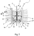
figure 2 montre schématiquement une vue de côté du dispositif de soudage de lafigure 1 . - Le dispositif de soudage 1, représenté sur les
figures 1 et2 , est destiné à souder de façon rapide des pièces 2, 3 en matériaux composites thermoplastiques compatibles (à fibres continues ou à fibres longues, courtes ou sans renfort), tels qu'une peau et un pied de clip par exemple. Les pièces 2, 3 comprennent des fibres de carbone alignées selon une direction principale DP et noyées dans une résine, les fibres formant des plis parallèles à un plan dit plan principal PP. Ce plan principal PP est perpendiculaire à une direction secondaire Di, le long de laquelle peuvent se positionner des points de contact entre plis lors de la fabrication des pièces 2, 3. Pour ce faire, le dispositif 1 comprend notamment un support 25, une unité de génération de pression 17 et une unité de chauffage 18. - L'unité de chauffage 18 comprend un inducteur bifacial 19 et est configurée pour générer un champ magnétique 7 alternatif homogène dans un ensemble 21 comprenant les deux pièces 2 et 3 et un absorbeur de champ 4, comme représenté sur la
figure 2 , pendant une durée prédéfinie. - L'invention n'est cependant pas limitée au soudage de deux pièces, et pourrait être appliquée à plusieurs pièces à assembler ensemble, un absorbeur de champ étant alors disposé entre chaque pièce.
- Comme représenté sur la
figure 1 , l'unité de chauffage 18 comprend en plus de l'inducteur bifacial 19, un générateur de courant électrique alternatif 14, et des moyens 15 d'adaptation de ce courant. Dans les modes de réalisation représentés, l'inducteur bifacial 19 comprend deux parois 5, 6 parallèles, espacées entre elles et formant respectivement une paire de bobines de Helmholtz qui sont reliées aux moyens 15 et qui génèrent un champ magnétique alternatif homogène entre les bobines. Chaque bobine de Helmholtz comprend au moins une spire circulaire 5A, 6A de rayon défini, les deux bobines étant sensiblement identiques. Un courant électrique circulant dans la spire produit un champ magnétique, selon une direction d'incidence DB, représentée sur lafigure 2 par des lignes de champ 7 perpendiculaires au plan des spires 5A, 6A. Les deux bobines sont agencées parallèlement, à une distance l'une de l'autre sensiblement égale à leur rayon. Ainsi, un champ magnétique homogène est obtenu sur une zone circulaire. - Alternativement, les bobines de Helmholtz peuvent comprendre plusieurs spires 5A, 6A activables indépendamment les unes des autres, afin d'adapter la puissance du champ magnétique aux types de matériaux composites à souder.
- Comme illustré sur la
figure 2 , le dispositif de soudage 1 comprend, de plus, des moyens d'inclinaison 27 du support 25 destinés à orienter les pièces 2,3. Par exemple, les moyens d'inclinaison 27 comprennent un ensemble d'au moins trois vérins pneumatiques situés sous des côtés du support 25. Ainsi, par un jeu de mouvements différents d'un vérin à l'autre, les pièces 2,3 peuvent être inclinées selon au moins trois axes afin qu'un angle entre la direction d'incidence DB du champ magnétique 7 et le plan principal PP des plis des fibres de carbone soit : - différent de 90°, afin de limiter un chauffage par circulation de courants induits le long de la direction principale DP des fibres de carbone ; et
- différent de 0°, afin de limiter un chauffage par circulation de courants induits, sur les points de contacts entre plis, le long de la direction secondaire Di.
- Les moyens d'inclinaison 27 peuvent également être appliqués à l'inducteur bifacial 19. Dans cette variante de réalisation (non représentée), les deux parois 5, 6 de l'inducteur bifacial 19 sont orientées alors que le support 25, sur lequel l'ensemble 21 est disposé, reste fixe. Dans une autre variante non représentée, les moyens d'inclinaison 27 peuvent comporter des premiers éléments d'inclinaison appliqués à l'inducteur bifacial 19 et des seconds éléments d'inclinaison appliqués à l'ensemble 21.
- Pour souder deux pièces 2 et 3 en matériaux composites compatibles, un absorbeur de champ 4 est donc agencé à l'interface des deux pièces 2 et 3. L'absorbeur de champ 4 est configuré pour absorber le champ magnétique 7 émis par les bobines de Helmholtz. L'absorbeur de champ 4 est, par exemple, une résine polymère chargée en particules ferromagnétiques, telle que décrite dans le brevet
EP1326741 B1 . L'absorbeur de champ 4 comprend un matériau ferromagnétique (sous forme d'une grille ou sous forme de particules ferromagnétiques) dont la perméabilité magnétique relative est plus élevée que la perméabilité magnétique de la résine utilisée et que celle du carbone des fibres (perméabilité magnétique relative µ < 2 T.m.A-1), par exemple de la poudre de fer (perméabilité magnétique relative µ = 250 T.m.A-1 et température de Curie = 770°). - Dans un premier mode de réalisation, la grille ou les particules ferromagnétiques sont noyées dans un film de résine compatible avec ceux des deux pièces 2 et 3, et forment un élément d'interface 20 disposé entre les parois de contact des deux pièces 2 et 3, afin que le soudage s'effectue lors de la transformation des matériaux composites.
- Selon un autre mode de réalisation, les particules ferromagnétiques sont mélangées avec la résine du matériau composite sur la paroi de contact d'au moins l'une des pièces 2 et 3 au moment de la fabrication des pièces 2 et 3. Le matériau ferromagnétique se présente sous forme de particules ferromagnétiques sphériques noyées dans la résine, par exemple du polysulfone (PSU), avec des fractions volumiques allant de 10% à 20%. Le diamètre des particules ferromagnétiques est faible (entre 22 microns et 300 microns). L'homogénéité du mélange résine-particules est fonction du grade de la résine, de la granulométrie des particules de matériau ferromagnétique ainsi que de l'imprégnation entre la résine et les fibres de carbone (qualité de l'interface fibre/résine, viscosité de la résine, taux de porosité). Cet autre mode de réalisation permet de mettre directement en contact les deux pièces 2 et 3, sans avoir à prévoir pour le soudage un élément d'interface (tel que l'élément d'interface 20) contenant le matériau ferromagnétique entre les pièces 2 et 3.
- Les deux pièces 2 et 3, ainsi que l'absorbeur de champ 4 (intégré dans l'une des pièces 2 et 3 ou dans un élément d'interface 20), forment un ensemble 21 qui est maintenu par une pression de contact, représentée par une ou des flèches 9 sur les
figures 1 et2 , exercée par l'unité de génération de pression 17, au moyen d'éléments 10 d'application de pression. La pression de contact est dirigée de sorte que les pièces 2 et 3 sont pressées l'une contre l'autre. - L'ensemble 21, placé dans l'espace entre les bobines, subit l'effet du champ magnétique émis par les bobines, la grille en matériau ferromagnétique ou les particules ferromagnétiques produisant en particulier de la chaleur. Ainsi, l'absorbeur de champ 4 chauffe de façon homogène l'interface entre les deux pièces 2 et 3, grâce au champ magnétique uniformément réparti dans la zone 8 où est placé l'ensemble 21.
- Dans le cas du chauffage par hystérésis, l'homogénéité de la réponse thermique dans la surface est obtenue grâce à la régularité de la distribution surfacique des particules de matériau ferromagnétique (dans l'une des pièces 2 et 3 ou dans l'élément d'interface 20). L'incidence de la surface par rapport au champ et la forme de la surface à souder ne présentent pas d'impact sur la distribution thermique. Ce procédé est contraint, notamment, par la taille des particules ferromagnétiques, leur nature, l'intensité du champ magnétique 7 et sa fréquence.
- Pour garantir des niveaux de température appropriés à l'interface des pièces 2 et 3, on utilise un matériau ferromagnétique ayant comme caractéristique une température de Curie adaptée aux résines utilisées. Ainsi, le matériau ferromagnétique est choisi tel que sa température de Curie soit identique à une température définie, appelée "température de procédé", correspondant par exemple à la température de transformation de la résine augmentée d'une valeur de 0° à 50° selon la géométrie des pièces à souder. La température de Curie correspond à la température à laquelle le matériau ferromagnétique devient paramagnétique et perd, notamment, ses propriétés de conductions thermique et électrique. La température de transformation dépend de la nature de la résine et est, par exemple :
- soit la température de surfusion dans le cas où la résine des pièces 2, 3 est en matériau semi-cristallin ;
- soit la température de fusion (ou température de début de "ramollissement") dans le cas où la résine des pièces 2, 3 est en matériau amorphe ;
- soit la température de polymérisation dans le cas où la résine des pièces 2, 3 est en matériau thermodurcissable.
- Par exemple, dans le cas de fibres de carbone noyées dans une résine de polyétheréthercétone (désigné par PEEK), le matériau ferromagnétique utilisé peut être du NiFe5.
- La température de Curie est la température à laquelle le matériau ferromagnétique devient paramagnétique. Ce matériau ferromagnétique présente une sensibilité au champ magnétique 7 beaucoup plus importante que le matériau composite à souder. La conductivité, ainsi que la perméabilité magnétique des matériaux ferromagnétiques, évoluent en fonction de la température. A fréquence de champ magnétique fixe, la permittivité électrique des matériaux évolue également en fonction de la température et atteint un seuil au-delà duquel elle n'évolue plus.
- Par conséquent, l'application d'un champ magnétique 7 permet d'augmenter la température de l'ensemble 21 jusqu'à la température de Curie, à laquelle le matériau ferromagnétique perd son aimantation et se stabilise en température, ce qui permet d'obtenir une température de chauffage constante. La température du matériau ferromagnétique soumis à un champ magnétique suit un cycle d'hystérésis. Ces caractéristiques permettent donc de définir une fenêtre autour d'une température caractéristique du matériau ferromagnétique. En adaptant les paramètres inductifs tels que la fréquence du courant alternatif et la puissance injectée par le générateur 14, associés à une configuration de champ homogène, on génère un chauffage homogène à l'interface à un niveau de température maîtrisé et reproductible.
- On évite ainsi les variations de température sur les parois de contact, car le champ appliqué est homogène et agit sur le matériau ferromagnétique qui a un point de Curie spécifique correspondant à la température de transformation des matériaux composites.
- L'homogénéité du champ électromagnétique est en outre garantie par la géométrie de l'inducteur. Dans une bobine de Helmholtz, le champ est homogène dans la partie centrale (zone 8), sur un diamètre sensiblement équivalent au rayon des spires 5A, 6A.
- Dans le cas où les deux matériaux composites sont de natures différentes, on choisit la température de transformation la plus élevée des deux, afin que les deux matériaux soient transformés ensemble.
- Le champ magnétique 7 est maintenu pendant un temps défini afin d'obtenir une transformation suffisante des parois de contact. Une fois que le champ magnétique 7 est arrêté, l'ensemble 21 est maintenu en contact par les éléments 10 d'application de la pression de contact jusqu'à ce qu'il ait suffisamment refroidi.
- Ainsi, le dispositif 1 comprend, de plus, des moyens de refroidissement 23 (
figure 1 ). Dans un mode de réalisation préféré, les moyens de refroidissement 23 comprennent un ensemble de canaux de circulation d'un fluide, tel que de l'eau ou de l'air, sur l'ensemble 21, comme illustré par une flèche 24 sur lafigure 1 . Le refroidissement est atteint lorsque la température de l'ensemble 21 est redescendue en-dessous de la température de cristallisation des matériaux composites. Dans ce cas, le soudage entre les deux pièces 2 et 3 en matériaux composites est réalisé et la pression de contact, devenue inutile, est stoppée. - Dans un premier mode de réalisation de l'invention, l'ensemble 21 est maintenu immobile pendant le soudage dans l'inducteur bifacial 19.
- En outre, dans un second mode de réalisation de l'invention, le dispositif 1 comprend, de plus, des moyens de déplacement 22, qui sont aptes à déplacer l'ensemble 21 entre les bobines, comme représenté par une flèche 16 sur la figure 3. L'ensemble 21 est soumis à une translation dans la zone 8 où le champ magnétique 7 est homogène. La vitesse de déplacement de l'ensemble 21 (générée par les moyens de déplacement 22) est réglée de sorte que le temps d'exposition au champ magnétique 7 (entre les bobines) est suffisant pour atteindre la température de transformation des matériaux composites, et obtenir ainsi le soudage des pièces 2 et 3.
- Dans ce second mode de réalisation, une ligne de production permet de produire les pièces 2 et 3 assemblées en les faisant circuler dans un montage entre les deux bobines.
- Le champ magnétique 7 est appliqué avec des paramètres définis en fonction de la nature du matériau ferromagnétique, de la granulométrie des particules ou de la grille. Dans un mode de réalisation préféré, les fréquences sont élevées (de l'ordre du MHz), ainsi que les puissances (le champ magnétique 7 est supérieur à 5 000 A/m). De hautes fréquences (de 1 MHz à 10 MHz) assurent le chauffage de multiples domaines magnétiques dans les particules qui sont favorables à l'effet d'hystérésis. En outre, un champ magnétique élevé, supérieur à 5000 A/m, permet de mieux contrôler le chauffage grâce à la température de Curie. De plus, ces paramètres inductifs initient un chauffage par hystérésis et limitent un chauffage par circulation de courants induits.
- On notera que le dispositif selon l'invention permet de souder des géométries complexes de forme simple ou présentant une double courbure, ou bien qui comprennent des variations d'épaisseur.
Claims (10)
- Procédé de soudage par induction d'au moins deux pièces (2, 3) en matériaux composites comprenant des fibres de carbone noyées dans une résine et orientées selon une direction principale appartenant à un plan principal (PP), ledit procédé comprenant les étapes suivantes :a) formation d'au moins un absorbeur de champ (4) configuré pour absorber un champ magnétique (7) et comprenant un matériau ferromagnétique ;b) formation d'un ensemble (21) comprenant les pièces (2, 3) à souder et ledit au moins un absorbeur de champ (4) agencé au niveau de parois de contact des pièces (2, 3) ; etc) génération, pendant une durée prédéfinie, d'un champ magnétique (7) alternatif homogène dans l'ensemble (21) à l'aide d'un inducteur bifacial (19), selon une direction d'incidence (DB), de manière à chauffer les parois de contact de l'ensemble jusqu'à une température dite de procédé,caractérisé en ce que le procédé comprend de plus, une étape d'inclinaison d'au moins l'un des éléments suivants : l'ensemble (21) et l'inducteur bifacial (19), de manière à orienter la direction d'incidence (DB) du champ magnétique (7) par rapport au plan principal (PP) selon un angle différent de 90° et différent d'un angle nul.
- Procédé selon la revendication 1,
caractérisé en ce qu'il comprend une étape d'application d'une pression de contact (9) sur l'ensemble (21). - Procédé selon la revendication 2,
caractérisé en ce qu'il comprend une étape supplémentaire, postérieure à l'étape c) et consistant à refroidir l'ensemble (21) en maintenant la pression de contact (9), après un arrêt de la génération du champ magnétique (7) dans l'ensemble (21). - Procédé selon l'une quelconque des revendications précédentes, caractérisé en ce que la température de procédé est définie entre une température de transformation de la résine et une température supérieure à cette température de transformation de la résine d'au moins 50°C.
- Procédé selon l'une quelconque des revendications précédentes, caractérisé en ce qu'à l'étape c), l'ensemble (21) est déplacé par rapport à l'inducteur bifacial (19) suivant une vitesse de déplacement, la durée de génération du champ magnétique (7) dans l'ensemble (21) étant contrôlée en fonction de la vitesse de déplacement.
- Dispositif de soudage par induction d'au moins deux pièces (2, 3) en matériaux composites comprenant des fibres de carbone noyées dans une résine et orientées selon une direction principale appartenant à un plan principal (Pp), le dispositif (1) comportant au moins une unité de chauffage (18) pourvue d'au moins un inducteur bifacial (19) comprenant deux parois (5, 6) espacées entre elles et réparties de part et d'autre d'un support (25) sur lequel est disposé, en utilisation, un ensemble (21) comprenant les pièces (2, 3) à souder et un absorbeur de champ (4), l'absorbeur de champ (4) étant configuré pour absorber un champ magnétique (7) et comprenant un matériau ferromagnétique, l'absorbeur de champ (4) étant agencé au niveau de parois de contact des deux pièces (2, 3) à souder, de manière à les chauffer à une température dite de procédé, le dispositif (1) comportant, également, des moyens de génération (16) et des moyens d'adaptation (15) d'un courant alternatif destinés en utilisation à générer un champ magnétique (7) homogène entre les deux parois (5, 6) de l'inducteur bifacial (19),
caractérisé en ce que le dispositif (1) comprend, de plus, des moyens d'inclinaison (27) d'au moins l'un des éléments suivants : l'ensemble (21) et l'inducteur bifacial (19), de manière à orienter la direction d'incidence (DB) du champ magnétique (7) par rapport au plan principal (Pp) selon un angle différent de 90° et différent d'un angle nul. - Dispositif selon la revendication 6,
caractérisé en ce que chaque paroi de l'inducteur bifacial (19) comprend une bobine de Helmholtz. - Dispositif selon l'une des revendications 6 et 7,
caractérisé en ce que l'absorbeur de champ (4) comprend une grille ferromagnétique noyée dans un film de matériau composite compatible avec ceux des pièces (2, 3) à souder, et formant un élément d'interface (20). - Dispositif selon l'une des revendications 6 et 7,
caractérisé en ce que l'absorbeur de champ (4) comprend des particules ferromagnétiques noyées dans un film de matériau composite compatible avec ceux des pièces (2, 3) à souder, et formant un élément d'interface (20). - Dispositif selon l'une des revendications 6 et 7,
caractérisé en ce que l'absorbeur de champ (4) comprend des particules ferromagnétiques noyées dans la paroi de contact d'au moins l'une desdites pièces (2, 3).
Applications Claiming Priority (1)
| Application Number | Priority Date | Filing Date | Title |
|---|---|---|---|
| FR1451293A FR3017562B1 (fr) | 2014-02-18 | 2014-02-18 | Procede et dispositif de soudage par induction de pieces en materiaux composites. |
Publications (2)
| Publication Number | Publication Date |
|---|---|
| EP2907651A1 EP2907651A1 (fr) | 2015-08-19 |
| EP2907651B1 true EP2907651B1 (fr) | 2018-05-23 |
Family
ID=50424637
Family Applications (1)
| Application Number | Title | Priority Date | Filing Date |
|---|---|---|---|
| EP15151123.5A Not-in-force EP2907651B1 (fr) | 2014-02-18 | 2015-01-14 | Procédé et dispositif de soudage par induction de pièces en matériaux composites |
Country Status (3)
| Country | Link |
|---|---|
| US (1) | US9770892B2 (fr) |
| EP (1) | EP2907651B1 (fr) |
| FR (1) | FR3017562B1 (fr) |
Cited By (1)
| Publication number | Priority date | Publication date | Assignee | Title |
|---|---|---|---|---|
| US11685125B2 (en) | 2018-07-16 | 2023-06-27 | Arkema France | Method for welding parts made of thermoplastic material |
Families Citing this family (11)
| Publication number | Priority date | Publication date | Assignee | Title |
|---|---|---|---|---|
| FR3017560B1 (fr) * | 2014-02-18 | 2016-03-11 | Airbus Operations Sas | Procede et dispositif de consolidation et de mise en forme par induction d'une preforme en materiau composite. |
| DE102016008671B4 (de) * | 2016-07-20 | 2023-12-14 | Technische Universität Chemnitz | Verfahren zum induktiven Kontaktfügen |
| JP2019084781A (ja) * | 2017-11-09 | 2019-06-06 | トヨタ自動車株式会社 | 繊維強化熱可塑性樹脂部材の接合方法及び繊維強化熱可塑性樹脂部材の接合装置 |
| FR3083732A1 (fr) | 2018-07-16 | 2020-01-17 | Arkema France | Procédé de soudage de pièces à base de matériau thermoplastique |
| FR3083734B1 (fr) | 2018-07-16 | 2021-12-24 | Arkema France | Procede de soudage par induction de pieces a base de materiau thermoplastique |
| FR3083733A1 (fr) | 2018-07-16 | 2020-01-17 | Arkema France | Procédé de soudage par induction de pièces à base de matériau thermoplastique |
| IT201800020521A1 (it) * | 2018-12-20 | 2020-06-20 | Leonardo Spa | Materiale composito e relativo metodo di realizzazione |
| NL2022271B1 (en) * | 2018-12-20 | 2020-07-15 | Kok & Van Engelen Composite Structures B V | Tooling for use in a method for electromagnetic welding of molded parts, and method for manufacturing the tooling |
| FR3111582B1 (fr) | 2020-06-22 | 2022-08-19 | Safran | Procédé de fabrication d’une pièce en matériau thermoplastique intégrant des éléments chauffants |
| FR3111585B1 (fr) | 2020-06-22 | 2022-10-28 | Safran | Procédé de fabrication d’une pièce en matériau thermoplastique intégrant des charges métalliques |
| US20250042578A1 (en) * | 2023-07-31 | 2025-02-06 | Rohr, Inc. | Consolidating thermoplastic material with induction heating coil and heating plate(s) |
Family Cites Families (12)
| Publication number | Priority date | Publication date | Assignee | Title |
|---|---|---|---|---|
| US3461014A (en) * | 1964-06-11 | 1969-08-12 | Albert L James | Magnetic induction method for heat-sealing and bonding predetermined sealing areas |
| GB1161903A (en) * | 1966-07-12 | 1969-08-20 | Bahlsen Werner | Method and Apparatus for Bonding the Surfaces of Thermoplastic Resin. |
| DE2312179A1 (de) | 1973-03-12 | 1974-09-19 | Kalle Ag | Verfahren und vorrichtung zum verschweissen metallfolien enthaltender verbunde |
| SE464019B (sv) | 1989-03-13 | 1991-02-25 | Tetra Pak Holdings & Finance | Anordning foer kontinuerlig induktionssvetsning av foerpackningsmaterial |
| US5248864A (en) | 1991-07-30 | 1993-09-28 | E. I. Du Pont De Nemours And Company | Method for induction heating of composite materials |
| CA2282542A1 (fr) * | 1997-02-28 | 1998-09-03 | Robert Harlan Johnson Jr. | Agents chauffants a haute efficacite |
| US6939477B2 (en) * | 1997-06-06 | 2005-09-06 | Ashland, Inc. | Temperature-controlled induction heating of polymeric materials |
| ES2269395T3 (es) | 2000-05-02 | 2007-04-01 | Ashland Licensing And Intellectual Property Llc | Calentamiento por induccion a temperatura controlada de materiales polimericos. |
| WO2003026821A1 (fr) * | 2001-09-25 | 2003-04-03 | Gerhard Jack K | Appareil et procede de stratification par induction de materiaux composites renforces par des fibres conductrices |
| ATE456513T1 (de) * | 2007-03-06 | 2010-02-15 | Huettinger Elektronik Gmbh | Flexibler induktor für das induktive versiegeln von gebinden |
| DE202007003450U1 (de) * | 2007-03-06 | 2007-05-10 | Hüttinger Elektronik Gmbh + Co. Kg | Flexibler Induktor für das induktive Versiegeln von Gebinden |
| FR3017560B1 (fr) | 2014-02-18 | 2016-03-11 | Airbus Operations Sas | Procede et dispositif de consolidation et de mise en forme par induction d'une preforme en materiau composite. |
-
2014
- 2014-02-18 FR FR1451293A patent/FR3017562B1/fr not_active Expired - Fee Related
-
2015
- 2015-01-14 EP EP15151123.5A patent/EP2907651B1/fr not_active Not-in-force
- 2015-02-16 US US14/623,143 patent/US9770892B2/en not_active Expired - Fee Related
Non-Patent Citations (1)
| Title |
|---|
| None * |
Cited By (1)
| Publication number | Priority date | Publication date | Assignee | Title |
|---|---|---|---|---|
| US11685125B2 (en) | 2018-07-16 | 2023-06-27 | Arkema France | Method for welding parts made of thermoplastic material |
Also Published As
| Publication number | Publication date |
|---|---|
| US9770892B2 (en) | 2017-09-26 |
| FR3017562B1 (fr) | 2016-03-11 |
| FR3017562A1 (fr) | 2015-08-21 |
| US20150231869A1 (en) | 2015-08-20 |
| EP2907651A1 (fr) | 2015-08-19 |
Similar Documents
| Publication | Publication Date | Title |
|---|---|---|
| EP2907651A1 (fr) | Procédé et dispositif de soudage par induction de pièces en matériaux composites | |
| EP3823818B1 (fr) | Procédé de soudage de pièces à base de matériau thermoplastique | |
| CA2559925C (fr) | Procede pour chauffer des materiaux en vue de produire des objets et dispositif mettant en oeuvre ce procede | |
| EP2907642B1 (fr) | Procédé et dispositif de consolidation et de mise en forme par induction d'une préforme en matériau composite | |
| EP1924415B1 (fr) | Dispositif de transformation de materiaux utilisant un chauffage par induction | |
| US20160023433A1 (en) | Thermoplastic composite prepreg for automated fiber placement | |
| CA2875233C (fr) | Procede et dispositif pour le prechauffage d'un moule notamment de moulage par injection | |
| FR3083733A1 (fr) | Procédé de soudage par induction de pièces à base de matériau thermoplastique | |
| CN105694440A (zh) | 热塑复合材料的焊接方法及其中所用到的掺杂树脂 | |
| US9446574B2 (en) | Method for bonding plastics and method for releasing a bond in the plastic composite and a plastic composite | |
| EP3504057A1 (fr) | Outil de pressage a chaud, son procede de mise en oeuvre, installation et procede de fabrication correspondants | |
| FR3083732A1 (fr) | Procédé de soudage de pièces à base de matériau thermoplastique | |
| KR102790828B1 (ko) | 레이저 어블레이션을 적용하는 코팅에 사용되는 타겟 물질에 그래핀-기반 첨가제를 첨가하는 방법 | |
| WO2017103075A1 (fr) | Noyaux d'inductance monolithique integrant un drain thermique | |
| WO2010061094A1 (fr) | Dispositif de soudage a double épaulement | |
| EP3233428A1 (fr) | Procédé de fabrication d'un objet par fusion d'une poudre de polymère dans un dispositif de frittage de poudre | |
| FR3026044A1 (fr) | Procede de mise en forme a chaud d'un materiau thermoplastique et installation de mise en œuvre | |
| FR3084008A1 (fr) | Procede de soudage par induction mettant en œuvre un film polymere composite conducteur et/ou magnetique | |
| WO2023194490A1 (fr) | Procédé de fabrication additive d'un objet magnétique | |
| FR3157240A1 (fr) | Moule pour dispositif de frittage assisté par courant électrique pulsé | |
| WO2019110466A1 (fr) | Procédés de formage/soudage de pièces par impulsion magnétique | |
| FR3156628A3 (fr) | Enroulement électrique chauffant émettant uniquement dans un demi-espace . | |
| FR3033728A1 (fr) | Procede et dispositif de drapage et de soudage d’une bande textile comprenant un chauffage par micro-ondes | |
| FR2749534A1 (fr) | Procede de soudage de matieres plastiques et produits de soudage pour sa mise en oeuvre | |
| FR3120203A1 (fr) | Dispositif de fabrication additive par fusion sur lit de poudre |
Legal Events
| Date | Code | Title | Description |
|---|---|---|---|
| PUAI | Public reference made under article 153(3) epc to a published international application that has entered the european phase |
Free format text: ORIGINAL CODE: 0009012 |
|
| AK | Designated contracting states |
Kind code of ref document: A1 Designated state(s): AL AT BE BG CH CY CZ DE DK EE ES FI FR GB GR HR HU IE IS IT LI LT LU LV MC MK MT NL NO PL PT RO RS SE SI SK SM TR |
|
| AX | Request for extension of the european patent |
Extension state: BA ME |
|
| 17P | Request for examination filed |
Effective date: 20160219 |
|
| RBV | Designated contracting states (corrected) |
Designated state(s): AL AT BE BG CH CY CZ DE DK EE ES FI FR GB GR HR HU IE IS IT LI LT LU LV MC MK MT NL NO PL PT RO RS SE SI SK SM TR |
|
| GRAP | Despatch of communication of intention to grant a patent |
Free format text: ORIGINAL CODE: EPIDOSNIGR1 |
|
| STAA | Information on the status of an ep patent application or granted ep patent |
Free format text: STATUS: GRANT OF PATENT IS INTENDED |
|
| RIC1 | Information provided on ipc code assigned before grant |
Ipc: B29C 65/78 20060101ALI20180206BHEP Ipc: B29L 7/00 20060101ALN20180206BHEP Ipc: H05B 6/40 20060101ALN20180206BHEP Ipc: B29K 307/04 20060101ALN20180206BHEP Ipc: H05B 6/10 20060101ALN20180206BHEP Ipc: B29C 65/36 20060101AFI20180206BHEP |
|
| INTG | Intention to grant announced |
Effective date: 20180220 |
|
| GRAS | Grant fee paid |
Free format text: ORIGINAL CODE: EPIDOSNIGR3 |
|
| GRAA | (expected) grant |
Free format text: ORIGINAL CODE: 0009210 |
|
| STAA | Information on the status of an ep patent application or granted ep patent |
Free format text: STATUS: THE PATENT HAS BEEN GRANTED |
|
| AK | Designated contracting states |
Kind code of ref document: B1 Designated state(s): AL AT BE BG CH CY CZ DE DK EE ES FI FR GB GR HR HU IE IS IT LI LT LU LV MC MK MT NL NO PL PT RO RS SE SI SK SM TR |
|
| REG | Reference to a national code |
Ref country code: GB Ref legal event code: FG4D Free format text: NOT ENGLISH |
|
| REG | Reference to a national code |
Ref country code: CH Ref legal event code: EP |
|
| REG | Reference to a national code |
Ref country code: IE Ref legal event code: FG4D Free format text: LANGUAGE OF EP DOCUMENT: FRENCH |
|
| REG | Reference to a national code |
Ref country code: AT Ref legal event code: REF Ref document number: 1001170 Country of ref document: AT Kind code of ref document: T Effective date: 20180615 |
|
| REG | Reference to a national code |
Ref country code: DE Ref legal event code: R096 Ref document number: 602015011321 Country of ref document: DE |
|
| REG | Reference to a national code |
Ref country code: NL Ref legal event code: MP Effective date: 20180523 |
|
| REG | Reference to a national code |
Ref country code: LT Ref legal event code: MG4D |
|
| PG25 | Lapsed in a contracting state [announced via postgrant information from national office to epo] |
Ref country code: SE Free format text: LAPSE BECAUSE OF FAILURE TO SUBMIT A TRANSLATION OF THE DESCRIPTION OR TO PAY THE FEE WITHIN THE PRESCRIBED TIME-LIMIT Effective date: 20180523 Ref country code: FI Free format text: LAPSE BECAUSE OF FAILURE TO SUBMIT A TRANSLATION OF THE DESCRIPTION OR TO PAY THE FEE WITHIN THE PRESCRIBED TIME-LIMIT Effective date: 20180523 Ref country code: BG Free format text: LAPSE BECAUSE OF FAILURE TO SUBMIT A TRANSLATION OF THE DESCRIPTION OR TO PAY THE FEE WITHIN THE PRESCRIBED TIME-LIMIT Effective date: 20180823 Ref country code: LT Free format text: LAPSE BECAUSE OF FAILURE TO SUBMIT A TRANSLATION OF THE DESCRIPTION OR TO PAY THE FEE WITHIN THE PRESCRIBED TIME-LIMIT Effective date: 20180523 Ref country code: NO Free format text: LAPSE BECAUSE OF FAILURE TO SUBMIT A TRANSLATION OF THE DESCRIPTION OR TO PAY THE FEE WITHIN THE PRESCRIBED TIME-LIMIT Effective date: 20180823 Ref country code: ES Free format text: LAPSE BECAUSE OF FAILURE TO SUBMIT A TRANSLATION OF THE DESCRIPTION OR TO PAY THE FEE WITHIN THE PRESCRIBED TIME-LIMIT Effective date: 20180523 |
|
| PG25 | Lapsed in a contracting state [announced via postgrant information from national office to epo] |
Ref country code: GR Free format text: LAPSE BECAUSE OF FAILURE TO SUBMIT A TRANSLATION OF THE DESCRIPTION OR TO PAY THE FEE WITHIN THE PRESCRIBED TIME-LIMIT Effective date: 20180824 Ref country code: NL Free format text: LAPSE BECAUSE OF FAILURE TO SUBMIT A TRANSLATION OF THE DESCRIPTION OR TO PAY THE FEE WITHIN THE PRESCRIBED TIME-LIMIT Effective date: 20180523 Ref country code: HR Free format text: LAPSE BECAUSE OF FAILURE TO SUBMIT A TRANSLATION OF THE DESCRIPTION OR TO PAY THE FEE WITHIN THE PRESCRIBED TIME-LIMIT Effective date: 20180523 Ref country code: LV Free format text: LAPSE BECAUSE OF FAILURE TO SUBMIT A TRANSLATION OF THE DESCRIPTION OR TO PAY THE FEE WITHIN THE PRESCRIBED TIME-LIMIT Effective date: 20180523 Ref country code: RS Free format text: LAPSE BECAUSE OF FAILURE TO SUBMIT A TRANSLATION OF THE DESCRIPTION OR TO PAY THE FEE WITHIN THE PRESCRIBED TIME-LIMIT Effective date: 20180523 |
|
| REG | Reference to a national code |
Ref country code: AT Ref legal event code: MK05 Ref document number: 1001170 Country of ref document: AT Kind code of ref document: T Effective date: 20180523 |
|
| PG25 | Lapsed in a contracting state [announced via postgrant information from national office to epo] |
Ref country code: EE Free format text: LAPSE BECAUSE OF FAILURE TO SUBMIT A TRANSLATION OF THE DESCRIPTION OR TO PAY THE FEE WITHIN THE PRESCRIBED TIME-LIMIT Effective date: 20180523 Ref country code: CZ Free format text: LAPSE BECAUSE OF FAILURE TO SUBMIT A TRANSLATION OF THE DESCRIPTION OR TO PAY THE FEE WITHIN THE PRESCRIBED TIME-LIMIT Effective date: 20180523 Ref country code: RO Free format text: LAPSE BECAUSE OF FAILURE TO SUBMIT A TRANSLATION OF THE DESCRIPTION OR TO PAY THE FEE WITHIN THE PRESCRIBED TIME-LIMIT Effective date: 20180523 Ref country code: AT Free format text: LAPSE BECAUSE OF FAILURE TO SUBMIT A TRANSLATION OF THE DESCRIPTION OR TO PAY THE FEE WITHIN THE PRESCRIBED TIME-LIMIT Effective date: 20180523 Ref country code: DK Free format text: LAPSE BECAUSE OF FAILURE TO SUBMIT A TRANSLATION OF THE DESCRIPTION OR TO PAY THE FEE WITHIN THE PRESCRIBED TIME-LIMIT Effective date: 20180523 Ref country code: PL Free format text: LAPSE BECAUSE OF FAILURE TO SUBMIT A TRANSLATION OF THE DESCRIPTION OR TO PAY THE FEE WITHIN THE PRESCRIBED TIME-LIMIT Effective date: 20180523 Ref country code: SK Free format text: LAPSE BECAUSE OF FAILURE TO SUBMIT A TRANSLATION OF THE DESCRIPTION OR TO PAY THE FEE WITHIN THE PRESCRIBED TIME-LIMIT Effective date: 20180523 |
|
| REG | Reference to a national code |
Ref country code: DE Ref legal event code: R097 Ref document number: 602015011321 Country of ref document: DE |
|
| PG25 | Lapsed in a contracting state [announced via postgrant information from national office to epo] |
Ref country code: IT Free format text: LAPSE BECAUSE OF FAILURE TO SUBMIT A TRANSLATION OF THE DESCRIPTION OR TO PAY THE FEE WITHIN THE PRESCRIBED TIME-LIMIT Effective date: 20180523 Ref country code: SM Free format text: LAPSE BECAUSE OF FAILURE TO SUBMIT A TRANSLATION OF THE DESCRIPTION OR TO PAY THE FEE WITHIN THE PRESCRIBED TIME-LIMIT Effective date: 20180523 |
|
| PLBE | No opposition filed within time limit |
Free format text: ORIGINAL CODE: 0009261 |
|
| STAA | Information on the status of an ep patent application or granted ep patent |
Free format text: STATUS: NO OPPOSITION FILED WITHIN TIME LIMIT |
|
| 26N | No opposition filed |
Effective date: 20190226 |
|
| PG25 | Lapsed in a contracting state [announced via postgrant information from national office to epo] |
Ref country code: SI Free format text: LAPSE BECAUSE OF FAILURE TO SUBMIT A TRANSLATION OF THE DESCRIPTION OR TO PAY THE FEE WITHIN THE PRESCRIBED TIME-LIMIT Effective date: 20180523 |
|
| PG25 | Lapsed in a contracting state [announced via postgrant information from national office to epo] |
Ref country code: MC Free format text: LAPSE BECAUSE OF FAILURE TO SUBMIT A TRANSLATION OF THE DESCRIPTION OR TO PAY THE FEE WITHIN THE PRESCRIBED TIME-LIMIT Effective date: 20180523 |
|
| REG | Reference to a national code |
Ref country code: CH Ref legal event code: PL |
|
| PG25 | Lapsed in a contracting state [announced via postgrant information from national office to epo] |
Ref country code: LU Free format text: LAPSE BECAUSE OF NON-PAYMENT OF DUE FEES Effective date: 20190114 |
|
| REG | Reference to a national code |
Ref country code: BE Ref legal event code: MM Effective date: 20190131 |
|
| REG | Reference to a national code |
Ref country code: IE Ref legal event code: MM4A |
|
| PG25 | Lapsed in a contracting state [announced via postgrant information from national office to epo] |
Ref country code: AL Free format text: LAPSE BECAUSE OF FAILURE TO SUBMIT A TRANSLATION OF THE DESCRIPTION OR TO PAY THE FEE WITHIN THE PRESCRIBED TIME-LIMIT Effective date: 20180523 Ref country code: BE Free format text: LAPSE BECAUSE OF NON-PAYMENT OF DUE FEES Effective date: 20190131 |
|
| PG25 | Lapsed in a contracting state [announced via postgrant information from national office to epo] |
Ref country code: CH Free format text: LAPSE BECAUSE OF NON-PAYMENT OF DUE FEES Effective date: 20190131 Ref country code: LI Free format text: LAPSE BECAUSE OF NON-PAYMENT OF DUE FEES Effective date: 20190131 |
|
| PG25 | Lapsed in a contracting state [announced via postgrant information from national office to epo] |
Ref country code: IE Free format text: LAPSE BECAUSE OF NON-PAYMENT OF DUE FEES Effective date: 20190114 |
|
| PG25 | Lapsed in a contracting state [announced via postgrant information from national office to epo] |
Ref country code: TR Free format text: LAPSE BECAUSE OF FAILURE TO SUBMIT A TRANSLATION OF THE DESCRIPTION OR TO PAY THE FEE WITHIN THE PRESCRIBED TIME-LIMIT Effective date: 20180523 |
|
| PG25 | Lapsed in a contracting state [announced via postgrant information from national office to epo] |
Ref country code: MT Free format text: LAPSE BECAUSE OF FAILURE TO SUBMIT A TRANSLATION OF THE DESCRIPTION OR TO PAY THE FEE WITHIN THE PRESCRIBED TIME-LIMIT Effective date: 20180523 Ref country code: PT Free format text: LAPSE BECAUSE OF FAILURE TO SUBMIT A TRANSLATION OF THE DESCRIPTION OR TO PAY THE FEE WITHIN THE PRESCRIBED TIME-LIMIT Effective date: 20180924 |
|
| PG25 | Lapsed in a contracting state [announced via postgrant information from national office to epo] |
Ref country code: CY Free format text: LAPSE BECAUSE OF FAILURE TO SUBMIT A TRANSLATION OF THE DESCRIPTION OR TO PAY THE FEE WITHIN THE PRESCRIBED TIME-LIMIT Effective date: 20180523 |
|
| PG25 | Lapsed in a contracting state [announced via postgrant information from national office to epo] |
Ref country code: IS Free format text: LAPSE BECAUSE OF FAILURE TO SUBMIT A TRANSLATION OF THE DESCRIPTION OR TO PAY THE FEE WITHIN THE PRESCRIBED TIME-LIMIT Effective date: 20180923 |
|
| PG25 | Lapsed in a contracting state [announced via postgrant information from national office to epo] |
Ref country code: HU Free format text: LAPSE BECAUSE OF FAILURE TO SUBMIT A TRANSLATION OF THE DESCRIPTION OR TO PAY THE FEE WITHIN THE PRESCRIBED TIME-LIMIT; INVALID AB INITIO Effective date: 20150114 |
|
| PGFP | Annual fee paid to national office [announced via postgrant information from national office to epo] |
Ref country code: GB Payment date: 20220119 Year of fee payment: 8 Ref country code: DE Payment date: 20220119 Year of fee payment: 8 |
|
| PGFP | Annual fee paid to national office [announced via postgrant information from national office to epo] |
Ref country code: FR Payment date: 20220119 Year of fee payment: 8 |
|
| PG25 | Lapsed in a contracting state [announced via postgrant information from national office to epo] |
Ref country code: MK Free format text: LAPSE BECAUSE OF FAILURE TO SUBMIT A TRANSLATION OF THE DESCRIPTION OR TO PAY THE FEE WITHIN THE PRESCRIBED TIME-LIMIT Effective date: 20180523 |
|
| REG | Reference to a national code |
Ref country code: DE Ref legal event code: R119 Ref document number: 602015011321 Country of ref document: DE |
|
| GBPC | Gb: european patent ceased through non-payment of renewal fee |
Effective date: 20230114 |
|
| PG25 | Lapsed in a contracting state [announced via postgrant information from national office to epo] |
Ref country code: GB Free format text: LAPSE BECAUSE OF NON-PAYMENT OF DUE FEES Effective date: 20230114 Ref country code: DE Free format text: LAPSE BECAUSE OF NON-PAYMENT OF DUE FEES Effective date: 20230801 |
|
| PG25 | Lapsed in a contracting state [announced via postgrant information from national office to epo] |
Ref country code: FR Free format text: LAPSE BECAUSE OF NON-PAYMENT OF DUE FEES Effective date: 20230131 |