EP2907476A1 - Procédé de fabrication de bagues orthodontiques personnalisées - Google Patents
Procédé de fabrication de bagues orthodontiques personnalisées Download PDFInfo
- Publication number
- EP2907476A1 EP2907476A1 EP14154796.8A EP14154796A EP2907476A1 EP 2907476 A1 EP2907476 A1 EP 2907476A1 EP 14154796 A EP14154796 A EP 14154796A EP 2907476 A1 EP2907476 A1 EP 2907476A1
- Authority
- EP
- European Patent Office
- Prior art keywords
- bracket
- providing
- bracket body
- physical
- archwire
- Prior art date
- Legal status (The legal status is an assumption and is not a legal conclusion. Google has not performed a legal analysis and makes no representation as to the accuracy of the status listed.)
- Ceased
Links
Images

Classifications
-
- A—HUMAN NECESSITIES
- A61—MEDICAL OR VETERINARY SCIENCE; HYGIENE
- A61C—DENTISTRY; APPARATUS OR METHODS FOR ORAL OR DENTAL HYGIENE
- A61C13/00—Dental prostheses; Making same
- A61C13/0003—Making bridge-work, inlays, implants or the like
- A61C13/0004—Computer-assisted sizing or machining of dental prostheses
-
- A—HUMAN NECESSITIES
- A61—MEDICAL OR VETERINARY SCIENCE; HYGIENE
- A61C—DENTISTRY; APPARATUS OR METHODS FOR ORAL OR DENTAL HYGIENE
- A61C13/00—Dental prostheses; Making same
- A61C13/0003—Making bridge-work, inlays, implants or the like
- A61C13/0006—Production methods
- A61C13/0018—Production methods using laser
-
- A—HUMAN NECESSITIES
- A61—MEDICAL OR VETERINARY SCIENCE; HYGIENE
- A61C—DENTISTRY; APPARATUS OR METHODS FOR ORAL OR DENTAL HYGIENE
- A61C13/00—Dental prostheses; Making same
- A61C13/0003—Making bridge-work, inlays, implants or the like
- A61C13/0006—Production methods
- A61C13/0019—Production methods using three dimensional printing
-
- A—HUMAN NECESSITIES
- A61—MEDICAL OR VETERINARY SCIENCE; HYGIENE
- A61C—DENTISTRY; APPARATUS OR METHODS FOR ORAL OR DENTAL HYGIENE
- A61C13/00—Dental prostheses; Making same
- A61C13/0003—Making bridge-work, inlays, implants or the like
- A61C13/0022—Blanks or green, unfinished dental restoration parts
-
- A—HUMAN NECESSITIES
- A61—MEDICAL OR VETERINARY SCIENCE; HYGIENE
- A61C—DENTISTRY; APPARATUS OR METHODS FOR ORAL OR DENTAL HYGIENE
- A61C7/00—Orthodontics, i.e. obtaining or maintaining the desired position of teeth, e.g. by straightening, evening, regulating, separating, or by correcting malocclusions
- A61C7/002—Orthodontic computer assisted systems
-
- A—HUMAN NECESSITIES
- A61—MEDICAL OR VETERINARY SCIENCE; HYGIENE
- A61C—DENTISTRY; APPARATUS OR METHODS FOR ORAL OR DENTAL HYGIENE
- A61C7/00—Orthodontics, i.e. obtaining or maintaining the desired position of teeth, e.g. by straightening, evening, regulating, separating, or by correcting malocclusions
- A61C7/12—Brackets; Arch wires; Combinations thereof; Accessories therefor
- A61C7/14—Brackets; Fixing brackets to teeth
- A61C7/16—Brackets; Fixing brackets to teeth specially adapted to be cemented to teeth
-
- B—PERFORMING OPERATIONS; TRANSPORTING
- B22—CASTING; POWDER METALLURGY
- B22F—WORKING METALLIC POWDER; MANUFACTURE OF ARTICLES FROM METALLIC POWDER; MAKING METALLIC POWDER; APPARATUS OR DEVICES SPECIALLY ADAPTED FOR METALLIC POWDER
- B22F10/00—Additive manufacturing of workpieces or articles from metallic powder
- B22F10/20—Direct sintering or melting
- B22F10/28—Powder bed fusion, e.g. selective laser melting [SLM] or electron beam melting [EBM]
-
- B—PERFORMING OPERATIONS; TRANSPORTING
- B22—CASTING; POWDER METALLURGY
- B22F—WORKING METALLIC POWDER; MANUFACTURE OF ARTICLES FROM METALLIC POWDER; MAKING METALLIC POWDER; APPARATUS OR DEVICES SPECIALLY ADAPTED FOR METALLIC POWDER
- B22F10/00—Additive manufacturing of workpieces or articles from metallic powder
- B22F10/40—Structures for supporting workpieces or articles during manufacture and removed afterwards
-
- B—PERFORMING OPERATIONS; TRANSPORTING
- B22—CASTING; POWDER METALLURGY
- B22F—WORKING METALLIC POWDER; MANUFACTURE OF ARTICLES FROM METALLIC POWDER; MAKING METALLIC POWDER; APPARATUS OR DEVICES SPECIALLY ADAPTED FOR METALLIC POWDER
- B22F7/00—Manufacture of composite layers, workpieces, or articles, comprising metallic powder, by sintering the powder, with or without compacting wherein at least one part is obtained by sintering or compression
- B22F7/06—Manufacture of composite layers, workpieces, or articles, comprising metallic powder, by sintering the powder, with or without compacting wherein at least one part is obtained by sintering or compression of composite workpieces or articles from parts, e.g. to form tipped tools
- B22F7/08—Manufacture of composite layers, workpieces, or articles, comprising metallic powder, by sintering the powder, with or without compacting wherein at least one part is obtained by sintering or compression of composite workpieces or articles from parts, e.g. to form tipped tools with one or more parts not made from powder
-
- B—PERFORMING OPERATIONS; TRANSPORTING
- B33—ADDITIVE MANUFACTURING TECHNOLOGY
- B33Y—ADDITIVE MANUFACTURING, i.e. MANUFACTURING OF THREE-DIMENSIONAL [3-D] OBJECTS BY ADDITIVE DEPOSITION, ADDITIVE AGGLOMERATION OR ADDITIVE LAYERING, e.g. BY 3-D PRINTING, STEREOLITHOGRAPHY OR SELECTIVE LASER SINTERING
- B33Y10/00—Processes of additive manufacturing
-
- B—PERFORMING OPERATIONS; TRANSPORTING
- B33—ADDITIVE MANUFACTURING TECHNOLOGY
- B33Y—ADDITIVE MANUFACTURING, i.e. MANUFACTURING OF THREE-DIMENSIONAL [3-D] OBJECTS BY ADDITIVE DEPOSITION, ADDITIVE AGGLOMERATION OR ADDITIVE LAYERING, e.g. BY 3-D PRINTING, STEREOLITHOGRAPHY OR SELECTIVE LASER SINTERING
- B33Y80/00—Products made by additive manufacturing
-
- B—PERFORMING OPERATIONS; TRANSPORTING
- B22—CASTING; POWDER METALLURGY
- B22F—WORKING METALLIC POWDER; MANUFACTURE OF ARTICLES FROM METALLIC POWDER; MAKING METALLIC POWDER; APPARATUS OR DEVICES SPECIALLY ADAPTED FOR METALLIC POWDER
- B22F10/00—Additive manufacturing of workpieces or articles from metallic powder
- B22F10/80—Data acquisition or data processing
-
- Y—GENERAL TAGGING OF NEW TECHNOLOGICAL DEVELOPMENTS; GENERAL TAGGING OF CROSS-SECTIONAL TECHNOLOGIES SPANNING OVER SEVERAL SECTIONS OF THE IPC; TECHNICAL SUBJECTS COVERED BY FORMER USPC CROSS-REFERENCE ART COLLECTIONS [XRACs] AND DIGESTS
- Y02—TECHNOLOGIES OR APPLICATIONS FOR MITIGATION OR ADAPTATION AGAINST CLIMATE CHANGE
- Y02P—CLIMATE CHANGE MITIGATION TECHNOLOGIES IN THE PRODUCTION OR PROCESSING OF GOODS
- Y02P10/00—Technologies related to metal processing
- Y02P10/25—Process efficiency
Definitions
- the invention relates to a method of making a customized orthodontic bracket and in particular to a method in which a pre-manufactured physical bracket body is combined with a three-dimensionally built up bracket base. Further the invention relates to a bracket obtainable with the method of the invention.
- Orthodontic brackets are generally used in orthodontic treatments for moving one or more teeth from an initial position to a desired position in a patient's dentition.
- the initial position typically refers to a position at the beginning of an orthodontic treatment, for example a position in which the labial faces of the teeth are misaligned to each other, whereas in the desired position the labial faces of the same teeth may be generally aligned.
- the patient's teeth may be aligned relative to each other to provide the dentition with a more aesthetically pleasant appearance.
- Further one or more teeth may be moved within the dentition to compensate for a malocclusion.
- Such a movement of a tooth or teeth can be typically achieved by using one or more brackets attached to one or more teeth.
- the brackets are typically connected to an elastic archwire for applying forces to the teeth urging them toward desired positions over a longer term.
- orthodontic brackets are off-the-shelf products which are configured for use with clinical situations of different patients. Further there are customized orthodontic brackets which are typically made to fit with an individual clinical situation of one particular patient.
- US 2012/0015315 A1 discloses a customized orthodontic bracket system which includes a bracket having a customized bracket bonding pad for bonding the bracket to a tooth of a patient and a bracket slot adapted to receive a customized archwire.
- the customized archwire is adapted to be positioned in the bracket slot to form a precise bracket slot-archwire interface.
- brackets and bracket systems are on the market there is still a desire to provide brackets which on the one hand match an individual clinical situation and on the other hand are minimized in costs for manufacturing and costs for application to a patient's teeth.
- minimization of costs in the manufacturing must be balanced relative to the desired accuracy of the customized brackets.
- brackets should be placeable easily and precisely to a patients teeth, and should have a geometry allowing an orthodontic archwire to be attached or slidably coupled precisely at desired positions relative to the teeth.
- Further customized brackets should be sufficiently durable over the time period of an orthodontic treatment.
- available manufacturing methods for mass production of customized brackets may not be compatible with such precision and quality requirements, whereas available sufficiently precise and high quality manufacturing methods may not satisfy or fully satisfy requirements for mass production at commercially viable costs.
- a customized orthodontic bracket typically has a bracket base for attaching the bracket to a patient's tooth and a bracket body for retaining an archwire.
- the bracket base typically has a tooth facing side for bonding the bracket to the tooth.
- the bracket base of a customized orthodontic bracket typically is individually shaped in accordance to a shape of the tooth to which the bracket is intended to be bonded.
- the tooth facing side of the bracket base of the customized orthodontic bracket is typically overall shaped to conform to a portion or area of the outer tooth surface.
- the tooth facing side of the customized orthodontic bracket has a footprint (or outer periphery) and the portion of the outer tooth surface corresponds in size and shape to that footprint.
- the term "conform" in this context means that the overall shape of the tooth facing side and the overall shape of the tooth portion correspond to each other, although a surface structure of the tooth facing side may be different from the surface structure of the tooth.
- the tooth facing side may comprise a roughened surface or a surface having a plurality of retention features (for example a mesh-type surface or mushroom pins), but may still overall conform to the shape of the tooth portion.
- the method of the invention comprises the steps of:
- the invention is advantageous in that it allows a serial production of a part of a multiplicity of brackets while another part of these brackets can be customized to individual teeth of patients. Further the invention allows manufacturing of an archwire slot within the bracket body at a maximized accuracy to provide a precise and durable fit between the bracket body and the archwire, whereas the accuracy of the overall bracket shape can be adapted to the needs of an individual clinical situation of a patient. Further different materials can be used for the bracket base and the bracket body, for example to provide a relatively hard bracket body for durably holding the archwire and to provide a softer bracket base to prevent the bracket to break upon exposure of mechanical forces (for example during chewing action). The invention is further advantageous in that it helps minimizing costs in the manufacturing. Further, the invention does not require the use of expensive materials like gold.
- the pre-manufactured physical bracket body has an archwire slot for receiving an archwire.
- an archwire as used with brackets obtainable by the method of the invention extends at a rectangular cross-section and the archwire slot is shaped and sized to fit with at least two opposing sides of that cross-section.
- the connection between the archwire and the bracket body allows a torque to be transmitted between the archwire and the bracket.
- the step of providing a physical bracket base is performed in a three-dimensional material build-up device, sometime also referred to as "3D printer".
- the step of providing the pre-manufactured physical bracket body may further comprise positioning the bracket body from a place outside the material build-up device into the material build-up device.
- the bracket body may be pre-manufactured by processes other than a material build-up process, for example by casting and/or machining.
- both, the bracket base and the bracket body are initially pre-manufactured and subsequently joined, for example by assembly.
- the pre-manufactured bracket body preferably has a bracket base interface in the form of a surface for connection of the bracket body with the bracket base.
- the pre-manufactured bracket base preferably has a bracket body interface in the form of a surface for connection of the bracket base with the bracket body.
- the bracket base and the bracket body may be joined by welding, gluing or by a positive fit (for example a screw connection).
- the bracket base interface and the bracket body interface may be shaped for mating with one another in one definite position, for example one may have the negative shape of the other.
- the method comprises the step of building up the bracket base on the bracket body.
- the pre-manufactured bracket body also preferably has a bracket base interface in the form of a surface for connection of the bracket body with the bracket base.
- the bracket base interface is typically arranged opposite of the archwire slot.
- a bracket base interface is preferably used in this embodiment for building up the bracket base thereon by a material build-up process.
- the method may further comprise the step of providing a primer layer on the bracket body, in particular on the bracket base interface of the bracket body, and building up the bracket base on the primer layer.
- the primer layer may comprise a metal alloy and a flux melting agent.
- SLM Selective Laser Melting
- the method further comprises the steps of providing a plurality of differently shaped pre-manufactured physical bracket bodies.
- the step of providing the pre-manufactured physical bracket body according to the invention may comprise selecting a particular pre-manufactured physical bracket body out of the plurality of differently shaped pre-manufactured physical bracket bodies.
- the method may further comprise the step of providing a physical library holding several bracket bodies of the same shape.
- the library may hold several types of bracket bodies and further several bracket bodies of the same type.
- the differently shaped pre-manufactured physical bracket bodies may comprise bracket bodies each extending along a given longitudinal axis and in which the archwire slots are inclined at different angles relative to the respective longitudinal axis.
- brackets having any of a variety of possible prescriptive values of torque, tip, and angulation in three-dimensional space may be provided.
- the library may offer different types of brackets in an assorted manner, for example one type of brackets in which the archwire slot extends along an axis which is inclined by about 5 degrees relative to the longitudinal axis and further types in which the archwire slot extends along an axis which is inclined by about 10, 15, 20, 25, 30, 35, 40, 45, 50, 55, 60, 65, 70, 75, 80, 85 or 90 degrees and so forth.
- the library may further hold a type of brackets in which the archwire slot extends along the longitudinal axis.
- the skilled person will recognize that other angles, for example intermediate or additional angles, are possible as needed.
- the material build-up process is based on Selective Laser Melting (SLM), in particular Direct Metal Laser Sintering (DMLS).
- SLM Selective Laser Melting
- DMLS Direct Metal Laser Sintering
- the material for the material build-up process may be stainless steel, cobalt-chrome alloy, a gold alloy, a silver alloy and a titanium alloy. Therefore at least one or both of the bracket body and the bracket base may be made of one of a cobalt-chrome alloy, a gold alloy, a silver alloy and a titanium alloy. Other materials like any suitable stainless steel may be used.
- the method of the invention may further comprise steps for determining the shape of the bracket and in particular for determining the shape of the bracket base.
- the shape of the bracket and/or the shape of the bracket base may be provided in a computer processible format and used in the material build-up process to make the bracket/bracket base.
- the method may particularly comprise the steps of:
- the virtual model of the patient's teeth is obtained from scanning the actual teeth of the patient intra-orally, or from scanning a physical model (for example a plaster model cast from a dental impression) of the patient's teeth. It is further possible to scan a dental impression taken from the patient's teeth.
- a physical model for example a plaster model cast from a dental impression
- scan a dental impression taken from the patient's teeth Typically an area is identified on several of the patient's teeth within the virtual model. The identified area or a copy thereof is preferably provided as the virtual bonding surface.
- CAD Computer Aided Design
- the mentioned areas can be identified physically on the patient's teeth or the model of the patient's teeth and captured to provide the virtual bonding surface.
- the archwire position relative to the identified area or virtual bonding surface may be determined by computer aid.
- a three-dimensional virtual model of the archwire (for example in the form of a simple line) may be placed in relation to the virtual model of the patient's teeth by a user, for example by an orthodontist or a dental technician.
- the so-called straight wire approach is used, meaning that a U-shaped archwire model extending in a plane may be provided by the computer, and the user may electronically deform that archwire model toward the patient's dentition model, with or without deforming the archwire outside that plane.
- the bracket can be designed or configured as a connector between the archwire and the virtual bonding surface.
- the method therefore may comprise the step of providing the physical tooth facing side of the bracket base in a geometric relationship corresponding to the position of the identified area or virtual bonding surface relative to the archwire position of the bracket body.
- the design may be performed on a CAD system which is connectable to a library holding a plurality of standardized virtual bracket bodies.
- virtual bracket bodies preferably represent the physical bracket bodies used in the method of the invention.
- the CAD system preferably allows the bracket base to be designed based on the virtual bonding surface.
- the virtual bonding surface (or a copy thereof) may be used to form the shape of the tooth facing side of the bracket bonding pad and an offset of the virtual bonding surface may be used as a rear side or outward-facing side (opposite of the tooth facing side) of the bracket bonding pad.
- the bracket body may be selected and positioned such that it connects the archwire and the bonding pad to each other.
- a so formed computer design may be exported in the form of computer processible data to a material build-up device, for example an SLM device, in which the bracket is completed as described above.
- the method comprises the step of shortening the physical bracket body based on the archwire position and the identified area or virtual bonding surface.
- the library holding the physical bracket bodies may comprise precursors of the bracket bodies which form overlong versions of the bracket bodies, and the precursors may be cut to obtain the bracket body.
- the number of unique bracket bodies kept in the library may be minimized.
- the invention relates to a customized orthodontic bracket obtainable from the method of the invention.
- an orthodontic bracket may encompass, for example, bondable tubes, splints, buttons, cleats and other appliance as appropriate.
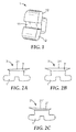
- Fig. 1 shows a physical bracket body 1.
- the bracket body 1 has an archwire slot 11 and, in the example, two wings 12, although in other examples the bracket body may have only one wing or three, four or more wings.
- the bracket body may further comprise one or more hooks (not shown).
- the wings 12 are configured for retaining an elastic tie (or rubber ring - not shown) and securing an archwire (also not shown) within the slot 11.
- the bracket body 1 in the example is pre-manufactured, for example cast, machined, or a combination thereof.
- the bracket body 1 is made of metal, for example, a cobalt-chrome alloy or a gold alloy.
- FIGS 2A, 2B and 2C show three customized orthodontic brackets 3, 3', 3" made up from generally identical bracket bodies 1 and three customized and therefore differently shaped bracket bases 2, 2' and 2".
- Each of the bracket bases 2, 2' and 2" has a tooth facing side 21, 21', 21" that is shaped to conform to an outer shape of a portion of a patient's tooth.
- the bracket body 1 and the bracket base 2/2'/2" are joined - as explained in more detail further below - to form a customized or patient specific orthodontic bracket 3/3'/3".
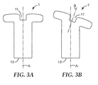
- Fig. 3 illustrates a library of differently shaped physical bracket bodies 1, 1'.
- a library may have a multiplicity of differently shaped physical bracket bodies rather than only two as shown by way of example only.
- the library particularly holds bracket bodies 1, 1' which extend along a longitudinal axis A but which on the other hand have archwire slots that are inclined at different angles relative to the respective longitudinal axis A.
- a first bracket body 1 has a first archwire slot 11 and a second bracket body 1' has a second archwire slot 11'.
- the first archwire slot 11 extends generally along the longitudinal axis A
- the second archwire slot 11' extends along a slot axis B being inclined with respect to the longitudinal axis A.
- the longitudinal axis may correspond to a center axis of a body in a dimension approximately between the archwire slot and the end of the body opposite thereof.
- the slot axis may correspond to a middle axis of the slot in a dimension between the slot opening and the opposite slot dead end.
- the axes A and B may be oriented along any angle relative to each other (including in directions out of the plane of the page in FIG. 3 ).
- the library may hold a plurality of bracket bodies each having a slot extending along a slot axis, wherein the individual slot axes are inclined with respect to the respective longitudinal axis A at different angels.
- the library may hold a series of bracket bodies having slot axes at inclination angles graded by about 5 degrees, for example a bracket body having a slot axis inclined by 5 degrees, a further bracket body having a slot axis inclined by 10 degrees and so forth.
- the bracket bodies 1, 1' of the library have a bracket base interface 13, 13'.
- the library may hold multiple bracket bodies having bracket base interfaces which are inclined at different angles, for example graded by angles of about 5 degrees.
- bracket body may be selected from the library as follows:
- a set-up model of the patient's dentition may be provided physically or in the form of a computer model.
- the set-up model typically represents the patient's teeth in the target position after the orthodontic treatment.
- a physical set-up model may be captured or scanned to provide a computer set-up model, further referred to as "virtual set-up model".
- the virtual set-up model may be used to define a path along which an archwire runs and to determine the archwire position relative to one, more than one, or each of the teeth in the patient's dentition.
- One or both of the virtual malocclusion model and the set-up model may be used to define a virtual bonding surface of the brackets.
- an area may be identified on the labial or lingual surface of individual teeth in the model.
- Such area is a representation of a physical area on a tooth on which a tooth facing side of the bracket may be bonded.
- the area is typically selected to be large enough to cover a sufficient area so that an orthodontist can place the bracket on the corresponding tooth in one definite position.
- the area further covers approximately 60-75 percent of the labial or lingual surface of a tooth to provide both good adhesion and to facilitate correct positioning.
- the bracket base may be designed, for example using Computer Aided Design (CAD) software to provide a virtual model of the bracket base. Further the bracket body may be selected based on the geometric relationship between the virtual bonding surface and the archwire position. For example if the virtual bonding surface is inclined with respect to a rectangular archwire a bracket body with an appropriately inclined bracket slot may be selected.
- CAD Computer Aided Design
- the design of the bracket base may be performed before or after selection of the bracket body. However the design of the bracket base is preferably also performed based on the geometric relationship between the virtual bonding surface and the archwire position.
- the library may further comprise bracket bodies having overlength. Such bracket bodies may be cut to a desired length to thereby form the bracket base interface at the shortened bracket body. Cutting may be performed to further provide the bracket base interface at a desired angle.
- Fig. 4 shows a bracket body 1 placed in a three-dimensional material build-up device 100 (not shown in detail).
- a three-dimensional material build-up device is also often referred to as "3D printer” in the technical field and in the example is a Selective Laser Melting (SLM) device.
- the bracket body 1 is placed at a determined reference position.
- Such a reference position preferably comprises information about a position of the bracket body 1 in a coordinate system of the device as well as an orientation of the bracket body 1 in that coordinate system.
- the bracket body 1 is embedded in a metal powder 102 with the bracket base interface 13 oriented toward the free surface of that powder 102.
- a thin layer of powder covers the bracket base interface 13 and a laser beam 101 is used to sinter the bracket base layerwise onto the bracket body 1.
- the positioning of the laser beam 101 is computer numerically controlled in accordance with the virtual model of the bracket base and in appropriate geometric relationship to the bracket body 1. As illustrated by the zig-zag line the bracket base interface 13 is roughened to maximize bond strength between the bracket base 2 and the bracket body.
- the skilled person will recognize alternative three-dimensional material build-up processes. For example a metal wire may be used to be melted off by the laser instead of using a powder bed.
- Fig. 5 shows a bracket body 1 and a bracket base 2 with a primer layer 13a arranged therebetween.
- primer layer 13a may maximize the quality of the sintering at the bracket base interface 13.
- the primer layer 13a may be made from an alloy having a high degree of compatibility and wetting with respect to both the bracket body 1 and the metal used in the SLM process.
- Fig. 6 shows a bracket body 1 and a bracket base 2 which are individually pre-manufactured and joined afterwards.
- the bracket base 2 may be manufactured using a three-dimensional build-up process.
- the bracket base 2 may have a bracket body interface 23 having the negative shape of the bracket base interface 13 of the bracket body 1.
- the bracket base 2 and the bracket body 1 can be mated in a predetermined and precise position with respect each other at the bracket body interface 23 and the bracket base interface 13, respectively.
Landscapes
- Health & Medical Sciences (AREA)
- Engineering & Computer Science (AREA)
- Manufacturing & Machinery (AREA)
- Animal Behavior & Ethology (AREA)
- Oral & Maxillofacial Surgery (AREA)
- Epidemiology (AREA)
- General Health & Medical Sciences (AREA)
- Public Health (AREA)
- Veterinary Medicine (AREA)
- Life Sciences & Earth Sciences (AREA)
- Dentistry (AREA)
- Chemical & Material Sciences (AREA)
- Materials Engineering (AREA)
- Physics & Mathematics (AREA)
- General Engineering & Computer Science (AREA)
- Plasma & Fusion (AREA)
- Composite Materials (AREA)
- Mechanical Engineering (AREA)
- Optics & Photonics (AREA)
- Dental Tools And Instruments Or Auxiliary Dental Instruments (AREA)
Priority Applications (9)
| Application Number | Priority Date | Filing Date | Title |
|---|---|---|---|
| EP14154796.8A EP2907476A1 (fr) | 2014-02-12 | 2014-02-12 | Procédé de fabrication de bagues orthodontiques personnalisées |
| KR1020167024370A KR20160119152A (ko) | 2014-02-12 | 2015-02-10 | 주문제작형 치과교정용 브래킷의 제조 방법 |
| MX2016010452A MX2016010452A (es) | 2014-02-12 | 2015-02-10 | Metodo para fabricar un corrector de ortodoncia a la medida. |
| EP15706110.2A EP3104806B1 (fr) | 2014-02-12 | 2015-02-10 | Procédé de fabrication de bagues orthodontiques personnalisées |
| US15/118,742 US10219876B2 (en) | 2014-02-12 | 2015-02-10 | Method of making a customized orthodontic bracket |
| PCT/US2015/015129 WO2015123170A1 (fr) | 2014-02-12 | 2015-02-10 | Procédé de fabrication d'un bracket orthodontique personnalisé |
| CN201580008292.6A CN105979907B (zh) | 2014-02-12 | 2015-02-10 | 制作定制正畸托槽的方法 |
| JP2016551140A JP6785159B2 (ja) | 2014-02-12 | 2015-02-10 | カスタマイズされた歯列矯正ブラケットを製造する方法 |
| BR112016018566A BR112016018566A2 (pt) | 2014-02-12 | 2015-02-10 | Método para fabricação de um bráquete ortodôntico personalizado |
Applications Claiming Priority (1)
| Application Number | Priority Date | Filing Date | Title |
|---|---|---|---|
| EP14154796.8A EP2907476A1 (fr) | 2014-02-12 | 2014-02-12 | Procédé de fabrication de bagues orthodontiques personnalisées |
Publications (1)
| Publication Number | Publication Date |
|---|---|
| EP2907476A1 true EP2907476A1 (fr) | 2015-08-19 |
Family
ID=50072992
Family Applications (2)
| Application Number | Title | Priority Date | Filing Date |
|---|---|---|---|
| EP14154796.8A Ceased EP2907476A1 (fr) | 2014-02-12 | 2014-02-12 | Procédé de fabrication de bagues orthodontiques personnalisées |
| EP15706110.2A Active EP3104806B1 (fr) | 2014-02-12 | 2015-02-10 | Procédé de fabrication de bagues orthodontiques personnalisées |
Family Applications After (1)
| Application Number | Title | Priority Date | Filing Date |
|---|---|---|---|
| EP15706110.2A Active EP3104806B1 (fr) | 2014-02-12 | 2015-02-10 | Procédé de fabrication de bagues orthodontiques personnalisées |
Country Status (8)
| Country | Link |
|---|---|
| US (1) | US10219876B2 (fr) |
| EP (2) | EP2907476A1 (fr) |
| JP (1) | JP6785159B2 (fr) |
| KR (1) | KR20160119152A (fr) |
| CN (1) | CN105979907B (fr) |
| BR (1) | BR112016018566A2 (fr) |
| MX (1) | MX2016010452A (fr) |
| WO (1) | WO2015123170A1 (fr) |
Cited By (1)
| Publication number | Priority date | Publication date | Assignee | Title |
|---|---|---|---|---|
| EP3831330A1 (fr) * | 2019-12-04 | 2021-06-09 | Oxilio Ltd | Systèmes et procédés pour générer une représentation 3d d'une bague orthodontique |
Families Citing this family (11)
| Publication number | Priority date | Publication date | Assignee | Title |
|---|---|---|---|---|
| US20160228214A1 (en) * | 2014-10-07 | 2016-08-11 | Orametrix, Inc. | Customized orthodontic interface attachment method and device |
| EP3547949B1 (fr) * | 2016-11-30 | 2023-11-29 | Dental Imaging Technologies Corporation | Procédé et système de retrait d'un appareil orthodontique d'un modèle de dentition virtuelle |
| CN110140086B (zh) | 2016-12-23 | 2023-05-23 | 3M创新有限公司 | 包括聚合物和可聚合组分的可打印组合物、制品和由其制备制品的方法 |
| EP3595572B1 (fr) * | 2017-03-15 | 2022-06-01 | 3M Innovative Properties Company | Appareil orthodontique amovible |
| US11317993B2 (en) * | 2018-02-09 | 2022-05-03 | Spartan Orthodontics Inc. | Orthodontic device for overbite correction |
| US11872101B2 (en) * | 2018-04-25 | 2024-01-16 | Lightforce Orthodontics, Inc. | Manufacture of patient-specific orthodontic brackets with improved base and retentive features |
| WO2019241253A1 (fr) | 2018-06-12 | 2019-12-19 | Lightforce Orthodontics, Inc. | Traitement et conception de céramique pour la fabrication directe d'accessoires d'aligneur transparent orthodontique lingual et labial personnalisés |
| US10278794B1 (en) | 2018-09-28 | 2019-05-07 | 3D Med Ag | Systems and methods for making orthodontic brackets |
| GB201904128D0 (en) * | 2019-03-26 | 2019-05-08 | Sst Tech Limited | Manufacturing method and components manufactured using the method |
| US10726949B1 (en) | 2019-12-05 | 2020-07-28 | Oxilio Ltd | Systems and methods for generating 3D-representation of tooth-specific platform for dental appliance |
| EP4183364A1 (fr) * | 2021-11-17 | 2023-05-24 | Orthodontic Research and Development, S.L. | Fabrication additive pour traitements orthodontiques |
Citations (3)
| Publication number | Priority date | Publication date | Assignee | Title |
|---|---|---|---|---|
| EP1464298A2 (fr) * | 2003-04-05 | 2004-10-06 | BEGO medical AG | Méthode de fabrication de prothèses destinées à être fixées sur des implants dentaires, ainsi que prothèse pour implant dentaire |
| FR2952803A1 (fr) * | 2009-11-25 | 2011-05-27 | H 32 | Procede de realisation d'un appareillage orthodontique individualise, et appareillage ainsi realise. |
| US20120015315A1 (en) | 2002-02-13 | 2012-01-19 | 3M Innovative Properties Company | Customized orthodontic bracket system |
Family Cites Families (14)
| Publication number | Priority date | Publication date | Assignee | Title |
|---|---|---|---|---|
| EP2266492A3 (fr) | 1999-12-29 | 2012-12-26 | Ormco Corporation | Procédé et appareil pour fabriquer un dispositif dentaire personnalisé |
| US6685468B1 (en) * | 2002-08-21 | 2004-02-03 | Tp Orthodontics, Inc. | Bondable orthodontic appliance with a polymer resin bonding base |
| KR100660646B1 (ko) * | 2005-02-01 | 2006-12-21 | 주식회사 에이치티 | 치열교정용 브라켓 및 그 부착방법 |
| FR2922753B1 (fr) * | 2007-10-31 | 2010-12-10 | Patrick Curiel | Procede de realisation d'un appareillage orthodontique individualise. |
| CN100586611C (zh) * | 2008-02-27 | 2010-02-03 | 华南理工大学 | 定制化舌侧正畸托槽的选区激光熔化直接制造方法 |
| US8813364B2 (en) * | 2009-12-18 | 2014-08-26 | 3M Innovative Properties Company | Methods for making layered dental appliances |
| US20130266906A1 (en) | 2010-06-07 | 2013-10-10 | The Regents Of The University Of California | Orthodontic systems |
| US9615897B2 (en) | 2010-09-10 | 2017-04-11 | Ormco Corporation | Self-ligating orthodontic bracket |
| DE102011003895A1 (de) | 2011-02-09 | 2012-08-09 | Hoang Viet-Ha Julius Vu | Kieferorthopädisches Bauteil mit einem Slot und zugehörige Bauteilhalteeinrichtung |
| DE102011003892A1 (de) | 2011-02-09 | 2012-08-09 | Hoang Viet-Ha Julius Vu | Verfahren zur Herstellung mindestens eines patientenspezifischen, modular aufgebauten Brackets und zugehöriges Bracket |
| DE102011003893A1 (de) | 2011-02-09 | 2012-08-09 | Hoang Viet-Ha Julius Vu | Verfahren zur Herstellung eines patientenspezifischen Pads und zugehöriges Pad |
| DE102011003894A1 (de) | 2011-02-09 | 2012-08-09 | Hoang Viet-Ha Julius Vu | Verfahren zur Herstellung eines patientenspezifischen Bracketbody und zugehöriger Bracketbody |
| EP2704539B1 (fr) * | 2012-09-04 | 2019-12-18 | Airbus Operations GmbH | Procédé de production d'un composant de structure d'avion comportant une peau extérieure pourvue de jauges de déformation résistives |
| EP2837356A1 (fr) * | 2013-08-14 | 2015-02-18 | 3M Innovative Properties Company | Attache orthodontique et son procédé de fabrication |
-
2014
- 2014-02-12 EP EP14154796.8A patent/EP2907476A1/fr not_active Ceased
-
2015
- 2015-02-10 EP EP15706110.2A patent/EP3104806B1/fr active Active
- 2015-02-10 MX MX2016010452A patent/MX2016010452A/es unknown
- 2015-02-10 KR KR1020167024370A patent/KR20160119152A/ko not_active Application Discontinuation
- 2015-02-10 BR BR112016018566A patent/BR112016018566A2/pt not_active Application Discontinuation
- 2015-02-10 WO PCT/US2015/015129 patent/WO2015123170A1/fr active Application Filing
- 2015-02-10 CN CN201580008292.6A patent/CN105979907B/zh not_active Expired - Fee Related
- 2015-02-10 US US15/118,742 patent/US10219876B2/en not_active Expired - Fee Related
- 2015-02-10 JP JP2016551140A patent/JP6785159B2/ja not_active Expired - Fee Related
Patent Citations (3)
| Publication number | Priority date | Publication date | Assignee | Title |
|---|---|---|---|---|
| US20120015315A1 (en) | 2002-02-13 | 2012-01-19 | 3M Innovative Properties Company | Customized orthodontic bracket system |
| EP1464298A2 (fr) * | 2003-04-05 | 2004-10-06 | BEGO medical AG | Méthode de fabrication de prothèses destinées à être fixées sur des implants dentaires, ainsi que prothèse pour implant dentaire |
| FR2952803A1 (fr) * | 2009-11-25 | 2011-05-27 | H 32 | Procede de realisation d'un appareillage orthodontique individualise, et appareillage ainsi realise. |
Cited By (2)
| Publication number | Priority date | Publication date | Assignee | Title |
|---|---|---|---|---|
| EP3831330A1 (fr) * | 2019-12-04 | 2021-06-09 | Oxilio Ltd | Systèmes et procédés pour générer une représentation 3d d'une bague orthodontique |
| US11273008B2 (en) | 2019-12-04 | 2022-03-15 | Oxilio Ltd | Systems and methods for generating 3D-representation of tooth-specific appliance |
Also Published As
| Publication number | Publication date |
|---|---|
| CN105979907B (zh) | 2018-08-07 |
| EP3104806A1 (fr) | 2016-12-21 |
| JP2017508510A (ja) | 2017-03-30 |
| KR20160119152A (ko) | 2016-10-12 |
| EP3104806B1 (fr) | 2019-03-27 |
| JP6785159B2 (ja) | 2020-11-18 |
| CN105979907A (zh) | 2016-09-28 |
| WO2015123170A1 (fr) | 2015-08-20 |
| MX2016010452A (es) | 2016-10-26 |
| US10219876B2 (en) | 2019-03-05 |
| BR112016018566A2 (pt) | 2017-08-08 |
| US20170049534A1 (en) | 2017-02-23 |
Similar Documents
| Publication | Publication Date | Title |
|---|---|---|
| EP3104806B1 (fr) | Procédé de fabrication de bagues orthodontiques personnalisées | |
| KR100647356B1 (ko) | 주문 생산형 치열 교정 기구의 모듈러 시스템 | |
| US10314673B2 (en) | System for producing a one-piece orthodontic jig and brackets | |
| US10028804B2 (en) | System for producing a one-piece orthodontic jig and attachments | |
| US20170281314A1 (en) | Method for prducing a positioning tray and the device therefor | |
| EP3076893B1 (fr) | Procédé pour fabriquer des attaches orthodontiques personnalisées | |
| CA2826326C (fr) | Procede de fabrication d'un corps de bague orthodontique specifique au patient et corps de bague ainsi obtenu | |
| JP7382312B2 (ja) | 歯科矯正ブラケット及び歯科矯正装置 | |
| EP3691564B1 (fr) | Appareil dentaire amovible comprenant des cavaliers | |
| RU2584650C2 (ru) | Способ изготовления индивидуального для пациента основания и соответствующее основание | |
| JP2014512859A (ja) | 少なくとも1つの患者固有でモジュール式に構成されているブラケットの作製方法およびこれに関連するブラケット | |
| US20190223984A1 (en) | Dental apparatus for bonding orthodontic appliance to dental arch and process thereof | |
| EP3937829A1 (fr) | Vis orthodontique ou orthopédique pour dentisterie et appareil orthodontique ou orthopédique pour dentisterie |
Legal Events
| Date | Code | Title | Description |
|---|---|---|---|
| PUAI | Public reference made under article 153(3) epc to a published international application that has entered the european phase |
Free format text: ORIGINAL CODE: 0009012 |
|
| AK | Designated contracting states |
Kind code of ref document: A1 Designated state(s): AL AT BE BG CH CY CZ DE DK EE ES FI FR GB GR HR HU IE IS IT LI LT LU LV MC MK MT NL NO PL PT RO RS SE SI SK SM TR |
|
| AX | Request for extension of the european patent |
Extension state: BA ME |
|
| STAA | Information on the status of an ep patent application or granted ep patent |
Free format text: STATUS: THE APPLICATION HAS BEEN REFUSED |
|
| 18R | Application refused |
Effective date: 20150928 |