EP2907192B1 - Antenna for unattended ground sensor - Google Patents
Antenna for unattended ground sensor Download PDFInfo
- Publication number
- EP2907192B1 EP2907192B1 EP13750124.3A EP13750124A EP2907192B1 EP 2907192 B1 EP2907192 B1 EP 2907192B1 EP 13750124 A EP13750124 A EP 13750124A EP 2907192 B1 EP2907192 B1 EP 2907192B1
- Authority
- EP
- European Patent Office
- Prior art keywords
- antenna
- conductor
- solid dielectric
- conducting pin
- sensor
- Prior art date
- Legal status (The legal status is an assumption and is not a legal conclusion. Google has not performed a legal analysis and makes no representation as to the accuracy of the status listed.)
- Active
Links
- 239000004020 conductor Substances 0.000 claims description 47
- 239000007787 solid Substances 0.000 claims description 34
- 125000006850 spacer group Chemical group 0.000 claims description 13
- 239000000463 material Substances 0.000 claims description 4
- 238000009434 installation Methods 0.000 claims description 2
- 239000000615 nonconductor Substances 0.000 claims description 2
- 230000001419 dependent effect Effects 0.000 claims 1
- 230000014759 maintenance of location Effects 0.000 description 8
- RYGMFSIKBFXOCR-UHFFFAOYSA-N Copper Chemical compound [Cu] RYGMFSIKBFXOCR-UHFFFAOYSA-N 0.000 description 3
- 230000005540 biological transmission Effects 0.000 description 3
- 239000010949 copper Substances 0.000 description 3
- 229910052802 copper Inorganic materials 0.000 description 3
- 238000002474 experimental method Methods 0.000 description 3
- 229910001369 Brass Inorganic materials 0.000 description 2
- 239000010951 brass Substances 0.000 description 2
- 238000001514 detection method Methods 0.000 description 2
- 238000003780 insertion Methods 0.000 description 2
- 230000037431 insertion Effects 0.000 description 2
- 238000000034 method Methods 0.000 description 2
- 230000010287 polarization Effects 0.000 description 2
- 229920001343 polytetrafluoroethylene Polymers 0.000 description 2
- 239000004810 polytetrafluoroethylene Substances 0.000 description 2
- 230000005855 radiation Effects 0.000 description 2
- 238000000926 separation method Methods 0.000 description 2
- -1 Polytetrafluoroethylene Polymers 0.000 description 1
- 230000000694 effects Effects 0.000 description 1
- 231100001261 hazardous Toxicity 0.000 description 1
- 229910000679 solder Inorganic materials 0.000 description 1
Images


Classifications
-
- H—ELECTRICITY
- H01—ELECTRIC ELEMENTS
- H01Q—ANTENNAS, i.e. RADIO AERIALS
- H01Q1/00—Details of, or arrangements associated with, antennas
- H01Q1/36—Structural form of radiating elements, e.g. cone, spiral, umbrella; Particular materials used therewith
-
- H—ELECTRICITY
- H01—ELECTRIC ELEMENTS
- H01Q—ANTENNAS, i.e. RADIO AERIALS
- H01Q1/00—Details of, or arrangements associated with, antennas
- H01Q1/04—Adaptation for subterranean or subaqueous use
-
- H—ELECTRICITY
- H01—ELECTRIC ELEMENTS
- H01Q—ANTENNAS, i.e. RADIO AERIALS
- H01Q1/00—Details of, or arrangements associated with, antennas
- H01Q1/12—Supports; Mounting means
- H01Q1/22—Supports; Mounting means by structural association with other equipment or articles
-
- H—ELECTRICITY
- H01—ELECTRIC ELEMENTS
- H01Q—ANTENNAS, i.e. RADIO AERIALS
- H01Q1/00—Details of, or arrangements associated with, antennas
- H01Q1/42—Housings not intimately mechanically associated with radiating elements, e.g. radome
-
- H—ELECTRICITY
- H01—ELECTRIC ELEMENTS
- H01Q—ANTENNAS, i.e. RADIO AERIALS
- H01Q9/00—Electrically-short antennas having dimensions not more than twice the operating wavelength and consisting of conductive active radiating elements
- H01Q9/04—Resonant antennas
- H01Q9/0407—Substantially flat resonant element parallel to ground plane, e.g. patch antenna
- H01Q9/0421—Substantially flat resonant element parallel to ground plane, e.g. patch antenna with a shorting wall or a shorting pin at one end of the element
-
- H—ELECTRICITY
- H01—ELECTRIC ELEMENTS
- H01Q—ANTENNAS, i.e. RADIO AERIALS
- H01Q9/00—Electrically-short antennas having dimensions not more than twice the operating wavelength and consisting of conductive active radiating elements
- H01Q9/04—Resonant antennas
- H01Q9/30—Resonant antennas with feed to end of elongated active element, e.g. unipole
- H01Q9/32—Vertical arrangement of element
- H01Q9/36—Vertical arrangement of element with top loading
-
- G—PHYSICS
- G01—MEASURING; TESTING
- G01V—GEOPHYSICS; GRAVITATIONAL MEASUREMENTS; DETECTING MASSES OR OBJECTS; TAGS
- G01V1/00—Seismology; Seismic or acoustic prospecting or detecting
- G01V1/16—Receiving elements for seismic signals; Arrangements or adaptations of receiving elements
-
- G—PHYSICS
- G01—MEASURING; TESTING
- G01V—GEOPHYSICS; GRAVITATIONAL MEASUREMENTS; DETECTING MASSES OR OBJECTS; TAGS
- G01V1/00—Seismology; Seismic or acoustic prospecting or detecting
- G01V1/16—Receiving elements for seismic signals; Arrangements or adaptations of receiving elements
- G01V1/162—Details
- G01V1/166—Arrangements for coupling receivers to the ground
-
- G—PHYSICS
- G08—SIGNALLING
- G08B—SIGNALLING OR CALLING SYSTEMS; ORDER TELEGRAPHS; ALARM SYSTEMS
- G08B13/00—Burglar, theft or intruder alarms
- G08B13/16—Actuation by interference with mechanical vibrations in air or other fluid
- G08B13/1654—Actuation by interference with mechanical vibrations in air or other fluid using passive vibration detection systems
- G08B13/1663—Actuation by interference with mechanical vibrations in air or other fluid using passive vibration detection systems using seismic sensing means
Landscapes
- Physics & Mathematics (AREA)
- Details Of Aerials (AREA)
- Support Of Aerials (AREA)
- Life Sciences & Earth Sciences (AREA)
- General Physics & Mathematics (AREA)
- Acoustics & Sound (AREA)
- Engineering & Computer Science (AREA)
- Environmental & Geological Engineering (AREA)
- Geology (AREA)
- Remote Sensing (AREA)
- General Life Sciences & Earth Sciences (AREA)
- Geophysics (AREA)
- Waveguide Aerials (AREA)
Description
- This invention relates to an antenna configured to be installed in an unattended ground sensor.
- Unattended ground sensor units are used as part of security systems for infrastructure and personnel protection. Typically a number of unattended ground sensor units are provided around the perimeter of a site to be protected or along another boundary. Each unattended ground sensor unit comprises at least one sensor for sensing a physical phenomenon in the region of the unit and often transmission means for transmitting signals away from the unit in dependence on the output of the sensor. Thus, for example, the sensor unit may include a seismic sensor for detecting vibrations in the ground which are indicative of a passing person, vehicle or other object. Similarly the sensor unit may include acoustic sensors, magnetometers, heat and light sensors and so on, each for a similar purpose of detecting the presence of a person or object or movement of a person or object in the region of the unit.
- Typically unattended ground sensors are connected together in a network and, for example, connected to a central control unit where the output of each of the sensor units can be monitored and determinations made regarding the presence or movement of people and/or objects in or around the site which is to be monitored.
- Unattended ground sensors typically have a whip antenna to allow them to communicate with one another and/or a central control unit. Whip antennas have been used because they are a simple design and can provide an omnidirectional radiation pattern. However, the present inventor has recognised that whip antennas may have certain drawbacks for unattended ground sensors. Firstly, whip antennas generally extend vertically from a sensor which means that they can be difficult to disguise or camouflage. Secondly, the whip antennas and/or external RF connector can be damaged, especially in the type of hazardous environment where unattended ground sensors may be deployed. Thirdly, whip antennas can be affected by wind, causing small movements of the ground sensor; these movements can be misinterpreted as a seismic event and may be the cause of false alarms/detections.
- It would be desirable to provide an antenna for an unattended ground sensor unit which is more covert, insofar it is relatively unobtrusive once installed, but yet is robust and easy to deploy. The present invention is aimed at providing unattended ground sensor units which address at least some of these issues.
- "A low-profile omnidirectional planar antenna with vertical polarization employing two inphase elements" by Junsuek Oh et al, GENERAL ASSEMBLY AND SCIENTIFIC SYMPOSIUM, 2011, IEEE, 13 August 2011 describes a technique for designing a lowprofile miniaturised omnidirectional planar antenna with vertical polarization. The antenna is provided with two short in-phase vertical elements separated by λ/2 in order to provide an omnidirectional radiation pattern.
JP2007274317 - The antenna may comprise one or more shorting pins connected to the first conductor and extending between the first and second conductors, wherein the one of more shorting pins are electrically connected to both the first and second conductors.
- In this way, a top-loaded antenna can be provided. This is advantageous because a top-loaded antenna is generally shorter than a whip antenna for a comparable application with a similar efficiency. This allows an unattended ground sensor that is more covert and can be more easily camouflaged. A top-loaded antenna can also be accommodated internally within an unattended ground sensor which means that the antenna is less vulnerable to deliberate or accidental damage. For example, a vehicle could be driven over an unattended ground sensor including such an antenna without causing damage. A top-loaded antenna is also less likely to be affected by wind, especially if the antenna can be located entirely within the ground sensor housing.
- The antenna conducting pin is preferably arranged so that electrical currents can be directed through it to the first conductor. The antenna conducting pin is preferably insulated from the second conductor, which is normally at a ground potential. It has been determined by experiment that the inclusion of one or more shorting pins can increase the antenna efficiency. Specifically, the shorting pins may help in matching the antenna to the driving circuit. Improved antenna efficiency may be determined by measuring the voltage standing wave ratio (VSWR).
- The antenna conducting pin may extend through a bore in the second conductor, and an electrical insulator may be provided between the second conductor and the antenna conducting pin.
- The antenna may comprise at least two shorting pins arranged on opposite sides of the antenna conducting pin. For example, the shorting pins may be diametrically opposite one another, either side of a tubular antenna conducting pin. This arrangement has been found to improve antenna efficiency for a given antenna volume.
- The one or more shorting pins may be made of a different material to the antenna conducting pin. In one embodiment the shorting pins are made of the same material as the first and second conducting surfaces. The shorting pins may be made of brass and the antenna conducting pin may be made of copper. It has been determined by experiment that this configuration can improve antenna efficiency for a given antenna volume.
- Preferably there is an antenna controller electrically connected to the conducting pin so that electrical currents can be directed through the conducting pin to the first conductor. The antenna controller may be provided on a circuit board and the circuit board may be attached to the second conductor and arranged on the opposite side to the first conductor. By attaching the circuit board to the underside of the second conductor it is possible to create a robust and compact antenna arrangement.
- The antenna may include a solid dielectric spacer arranged in the space between the first and second planar surfaces. Preferably the solid dielectric has a higher dielectric constant than air. This can allow the separation of the first and second planar surfaces to be reduced further, which is advantageous as it can reduce the physical size of the antenna. The solid dielectric may also improve the robustness of the antenna by resisting any mechanical forces that could otherwise bend or warp the first and second planar surfaces.
- The solid dielectric may be a material such as Polytetrafluoroethylene (PTFE).
- The solid dielectric preferably comprises a bore through which the conducting pin can extend. This arrangement can facilitate the assembly process so that the solid dielectric can be fitted onto the conducting pin.
- The solid dielectric spacer may comprise at least one bore to accommodate the or each shorting pin.
- The solid dielectric includes a keying feature that is engaged to resist its rotation. This may be especially important when there is more than one conducting pin because the solid dielectric would not be able to rotate without breaking the pins. By providing the keying feature the solid dielectric can be rotationally locked to prevent any damage to the conducting pins.
- The antenna includes a clamp for engaging the solid dielectric. Preferably the clamp can resist any movement of the solid dielectric in a vertical direction (i.e. in a direction that is substantially perpendicular to the first and second planar surfaces). The clamp may also be arranged to lock together all of the components of the antenna. In one arrangement the clamp may be built into the cap of an unattended ground sensor.
- The solid dielectric comprises a flange that is engaged by the clamp. The clamp also includes a keying feature that engages with the keying feature on the solid dielectric. Thus, the clamp can prevent vertical and rotational movement of the solid dielectric. It can be important to prevent the solid dielectric from rotating to prevent stress on the shorting pins which can be soldered to the first and second conductors.
- Preferably the frequency of operation is in the range of 800-1000MHz.
- Preferably still the antenna is designed to operate in the range of 825-950MHz. The antenna may be used at different frequencies in different regions of the world.
- In certain arrangements the frequency of operation could be below 825MHz.
- As the frequency reduces the size of the components in the antenna may need to increase in order to achieve the same efficiency. In a mobile/portable device this may mean that a clamp arrangement needs to secure a higher mass.
- The transmission range of the antenna may be designed to be at least twice the detection range. Thus, if two ground sensors are separated by the transmission range then any seismic activity between the sensors can be detected by at least one of them.
- According to another aspect of the present invention there is provided an unattended ground sensor comprising a housing for accommodating the antenna as described above. The unattended ground sensor is preferably arranged to be affixed to the ground so that any seismic vibrations can be detected. By enclosing the antenna within the housing the antenna can be protected. This can improve the reliability of the unattended ground sensor in comparison to a sensor with an external whip antenna. It may also be helpful in camouflaging the unattended ground sensor.
- Preferably the unattended ground sensor further comprises at least one sensor for sensing a physical phenomenon in the region of the unit and the antenna is arranged to transmit information regarding the sensed physical phenomenon. The unattended ground sensor unit may comprise a memory for storing data in dependence on the output of the sensor. The sensor unit may comprise a head portion and body portion with a threaded exterior surface. The head portion may comprise engagement portions for engaging with a tool for rotatingly driving the sensor unit during installation in the ground. Preferably the sensor is a seismic sensor. The separation between the cap and the first conductor can be optimised to minimise antenna detuning.
- Embodiments of the present invention will now be described, by way of example only, with reference to the accompanying drawings in which:
-
Figure 1 is a schematic side view of an unattended ground sensor unit in an embodiment of the invention; -
Figure 2 is a section on line A-A of the unattended ground sensor unit shown inFigure 1 ; -
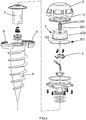
Figure 3 is an exploded view of the unattended ground sensor unit shown inFigure 1 ; -
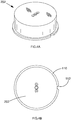
Figure 4A is a perspective view of a solid dielectric component for use in an antenna in an embodiment of the invention; -
Figure 4B is a top view of the solid dielectric component shown inFigure 4A ; -
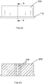
Figure 4C is a side view of the solid dielectric component shown inFigure 4A ; -
Figure 4D is a section on line A-A of the solid dielectric component shown inFigure 4C ; -
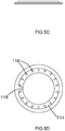
Figure 5A is a perspective view of a retention ring for use in an antenna in an embodiment of the invention; -
Figure 5B is a top view of the retention ring shown inFigure 5A ; -
Figure 5C is a side view of the retention ring shown inFigure 5A ; -
Figure 5D is a bottom view of the retention ring shown inFigure 5A ; and -
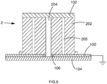
Figure 6 is a cross-sectional view of an antenna for assembly in an unattended ground sensor, in an embodiment of the invention. -
Figures 1-3 show an unattendedground sensor unit 30 for use as part of a security or surveillance system. The unattended ground sensor unit comprises abody portion 6 and ahead portion 5. Thebody portion 6 andhead portion 5 together form a housing within which other components of the sensor unit are disposed. In the present embodiment abattery 7 for powering the sensor unit is located in a compartment within thebody portion 6. Also provided within the ground sensor unit is a sensor 3, and anantenna 2. In the present embodiment the sensor 3 andantenna 2 are disposed in thehead portion 2 of the unit. This means that theantenna 2 is arranged to be above ground level when the unit is installed in the ground. A screw thread is provided on and around an external surface of thebody portion 6. Thus, if the sensor unit is rotated about the main axis whilst the sensor unit is inserted into the ground the thread will tend to draw the sensor unit into the surrounding ground at least up to a point where thehead portion 2 comes in contact with the surface of the ground. Thus when installed, or deployed, thebody portion 6 is located below ground level. - The
head portion 2 is provided with engaging recesses 26 (seeFigure 1 ) to aid in the act of rotating the sensor unit around the main axis for insertion of the sensor unit into the ground. In some cases a deployment tool may be provided for engaging with these recesses to aid in insertion of the unit. - As is apparent from
Figure 3 , theantenna 2 is accommodated mainly in thehead portion 5 of the unit. The antenna includes abase conductor 100 that is attached to a first side of a printedcircuit board 201. Antenna control circuitry is provided on a second side of the printedcircuit board 201 and the sensor 3 is also connected to the printed circuit board. Aretention ring 4 is provided to clamp the various components of theantenna 2 together. Locking rings 8, 9 are provided to clamp thehead portion 5 and thebody portion 6 together once all of the internal components have been assembled. In some arrangements a single locking ring may be provided. - Further detail of the
antenna 2 is apparent fromFigure 6 . Theantenna 2 comprises abase conductor 100 and atop conductor 102, both of which are circular plates, made of copper and arranged in a horizontal plane (with respect to the normal operating orientation of the unit). Anantenna rod 204, made of brass, is electrically connected to thetop conductor 102. A hole is provided in thebase conductor 100 and theantenna rod 204 extends through the hole to be connected to antenna control circuitry on a printedcircuit board 104 on the reverse side of thebase conductor 100. An insulatingring 106 is provided around theantenna rod 204 where it extends through thebase conductor 100 so that theantenna rod 204 is electrically insulated from thebase conductor 100. - The
base conductor 100 is connected to ground, and two shortingpins 205 are provided between thetop conductor 102 and thebase conductor 100. The shorting pins 205, made of copper, are provided on diametrically opposite sides of theantenna rod 204. - A
dielectric spacer 202 is provided between thebase conductor 100 and thetop conductor 102. Thedielectric spacer 202 includes bores to accommodate theantenna rod 204 and the shorting pins 205. - In operation, the antenna control circuitry is arranged to excite a current in the
antenna rod 102, and this current flows to thetop conductor 102. The shorting pins 205 carry the current to thebase conductor 100, where the current is earthed. It has been determined by experiment that this arrangement provides an improved antenna efficiency for the application of an unattended ground sensor. - Further detail of the
dielectric spacer 202 is shown inFigures 4A-D . Thedielectric spacer 202 is generally cylindrical withbores 108 to accommodate theantenna rod 204 and the shorting pins 205. Aflange 110 is provided at the bottom of thespacer 202, with respect to the normal operating orientation of theantenna 2, and theflange 110 includes a keying cut-out 112. Theflange 110 and the keying cut-out 112 are intended to be engaged by theretention ring 4, further details of which are apparent fromFigures 5A-D . - The
retention ring 4 is designed to fit over thedielectric spacer 202, and thering 4 includes asurface 114 withgripping teeth 116 for engaging theflange 110. A keyingengagement 118 is also provided for engaging the cut-out 112 in theflange 110 and resisting any rotational movement of thespacer 202. When theretention ring 4 is fitted in place any vertical or rotational movement of thespacer 202 can be resisted preventing damage to the solder connections between the rod and the conductors and the shorting pins and the conductors.
Claims (14)
- An antenna (2) for installation in an unattended ground sensor, the antenna comprising:a first conductor (102) having a first planar surface;a second conductor (100) having a second planar surface, wherein the second planar surface is substantially parallel to the first planar surface; an antenna conducting pin (204) connected to the first conductor and extending between the first and second conductors;a solid dielectric spacer (202) arranged in a space between the first and second planar surfaces; and a clamp (4) for engaging the solid dielectric and holding it in place, wherein the solid dielectric comprises a flange (110) that is engaged by the clamp (4), the flange of the solid dielectric includes a keying feature (112), and the clamp (4) includes a keying feature (118) that engages with the keying feature (112) on the flange of the solid dielectric to resist any rotation of the solid dielectric spacer (202).
- The antenna of claim 2 further comprising one or more shorting pins (205) connected to the first conductor and extending between the first and second conductors, wherein the one of more shorting pins are electrically connected to both the first and second conductors.
- The antenna of claim 2 wherein the antenna conducting pin (204) is electrically connected to the first conductor (102) and electrically insulated from the second conductor (100).
- The antenna of claim 3 wherein the antenna conducting pin (204) extends through a bore in the second conductor (100), and an electrical insulator (106) is provided between the second conductor (100) and the antenna conducting pin (204).
- The antenna of any of claims 2 to 4 wherein there are at least two shorting pins (205), arranged on opposite sides of the antenna conducting pin (204).
- The antenna of any of claims 2 to 5 wherein the one or more shorting pins (205) are made of a different material to the antenna conducting pin (204).
- The antenna of any of the preceding claims comprising an antenna controller electrically connected to the antenna conducting pin (204) so that electrical currents can be directed through the antenna conducting pin (204) to the first conductor (102).
- The antenna of claim 7 wherein the antenna controller is provided on a circuit board (201) and the circuit board attached to the opposite side of the second conductor (100) to the first conductor (102).
- The antenna of any of the preceding claims wherein the second conductor (100) is arranged at a fixed electrical potential.
- The antenna of any of the preceding claims wherein the solid dielectric (202) comprises a bore (108) through which the antenna conducting pin (204) can extend.
- The antenna of claim 2 or any one of claims 3 to 10 when dependent on claim 2 in which the solid dielectric spacer (202) comprises at least one bore (108) to accommodate the or each shorting pin (205).
- The antenna of any of the preceding claims wherein the frequency of operation is in the range of 800-1000MHz
- An unattended ground sensor (30) comprising a housing for accommodating the antenna of any of the preceding claims.
- The unattended ground sensor of claim 13 further comprising at least one sensor (3) for sensing a physical phenomenon in the region of the sensor, wherein the antenna is arranged to transmit information regarding the sensed physical phenomenon.
Applications Claiming Priority (2)
| Application Number | Priority Date | Filing Date | Title |
|---|---|---|---|
| GBGB1218158.2A GB201218158D0 (en) | 2012-10-10 | 2012-10-10 | Antenna for unattended ground sensor |
| PCT/GB2013/052149 WO2014057239A1 (en) | 2012-10-10 | 2013-08-12 | Antenna for unattended ground sensor |
Publications (2)
| Publication Number | Publication Date |
|---|---|
| EP2907192A1 EP2907192A1 (en) | 2015-08-19 |
| EP2907192B1 true EP2907192B1 (en) | 2018-01-31 |
Family
ID=47294570
Family Applications (1)
| Application Number | Title | Priority Date | Filing Date |
|---|---|---|---|
| EP13750124.3A Active EP2907192B1 (en) | 2012-10-10 | 2013-08-12 | Antenna for unattended ground sensor |
Country Status (8)
| Country | Link |
|---|---|
| US (1) | US9692111B2 (en) |
| EP (1) | EP2907192B1 (en) |
| JP (1) | JP6190885B2 (en) |
| KR (1) | KR102053891B1 (en) |
| GB (1) | GB201218158D0 (en) |
| MY (1) | MY171748A (en) |
| RU (1) | RU2637393C2 (en) |
| WO (1) | WO2014057239A1 (en) |
Families Citing this family (4)
| Publication number | Priority date | Publication date | Assignee | Title |
|---|---|---|---|---|
| EP3080642B1 (en) * | 2015-03-02 | 2021-06-16 | Total Se | System and method for coupling a seismic sensor to the ground |
| DE102016124981A1 (en) * | 2016-12-20 | 2018-06-21 | Endress+Hauser SE+Co. KG | Field device with antenna |
| EP3931905A1 (en) * | 2019-02-25 | 2022-01-05 | Husqvarna Ab | Antenna for soil sensors |
| CN112820074B (en) * | 2021-01-12 | 2023-01-10 | 焦昊 | Coal mine geological disaster early warning device |
Citations (1)
| Publication number | Priority date | Publication date | Assignee | Title |
|---|---|---|---|---|
| JP2007274317A (en) * | 2006-03-31 | 2007-10-18 | Furuno Electric Co Ltd | Patch antenna and receiver |
Family Cites Families (27)
| Publication number | Priority date | Publication date | Assignee | Title |
|---|---|---|---|---|
| US3930218A (en) * | 1974-01-16 | 1975-12-30 | Walker Hall Sears Inc | Geophone casings |
| JPH071866Y2 (en) * | 1988-09-30 | 1995-01-18 | 株式会社東芝 | Feed integrated SHF converter device |
| JPH05199032A (en) | 1991-09-11 | 1993-08-06 | Ngk Insulators Ltd | Plane antenna |
| JP2881102B2 (en) * | 1993-12-22 | 1999-04-12 | 松下電工株式会社 | Antenna unit |
| JP3206319B2 (en) * | 1994-07-29 | 2001-09-10 | ミツミ電機株式会社 | Antenna unit for navigation device |
| AU8256398A (en) * | 1997-06-13 | 1998-12-30 | Itron Inc. | Telemetry antenna system |
| JPH1166484A (en) * | 1997-08-08 | 1999-03-09 | Kubota Corp | Manhole cover antenna equipment and communication system |
| WO2001017064A1 (en) | 1999-08-27 | 2001-03-08 | Antennas America, Inc. | Compact planar inverted f antenna |
| US6300907B1 (en) | 2000-01-25 | 2001-10-09 | Badger Meter, Inc. | Antenna assembly for subsurface meter pits |
| US6819292B2 (en) | 2001-03-09 | 2004-11-16 | Arad Measuring Technologies Ltd | Meter register |
| JP3835291B2 (en) * | 2002-01-11 | 2006-10-18 | 日本電気株式会社 | Antenna element |
| US6788264B2 (en) * | 2002-06-17 | 2004-09-07 | Andrew Corporation | Low profile satellite antenna |
| US20040021606A1 (en) * | 2002-07-11 | 2004-02-05 | Alps Electric Co., Ltd. | Small plane antenna and composite antenna using the same |
| JP2004088198A (en) * | 2002-08-23 | 2004-03-18 | Matsushita Electric Ind Co Ltd | Monopole antenna system and communication system employing the same |
| US7050003B2 (en) * | 2003-04-04 | 2006-05-23 | General Motors Corporation | Low-profile antenna |
| JP2006126156A (en) * | 2004-11-01 | 2006-05-18 | Satoshi Nishizawa | Falling disaster warning device |
| US7365687B2 (en) | 2005-04-22 | 2008-04-29 | Elster Electricity, Llc | Antenna with disk radiator used in automatic meter reading (AMR) device |
| WO2007005138A2 (en) | 2005-05-27 | 2007-01-11 | Advanced Metering Data Systems, L.L.C. | Low profile helical planar radio antenna with plural conductors |
| DE102006038528B3 (en) * | 2006-08-17 | 2007-11-22 | Kathrein-Werke Kg | Tunable antenna e.g. patch antenna, for e.g. geostationary positioning, has electrically conductive structure galvanically or capacitively or serially connected with measuring surface or chassis by interconnecting electrical components |
| US7554460B2 (en) | 2006-09-25 | 2009-06-30 | Jeff Verkleeren | Utility meter antenna for ground mounted meter boxes |
| US20080137484A1 (en) | 2006-12-06 | 2008-06-12 | Gary Lee Scott | Seismic sensor housing, seismic sensor, and seismic acquisition system made therewith |
| US7498989B1 (en) * | 2007-04-26 | 2009-03-03 | Lockheed Martin Corporation | Stacked-disk antenna element with wings, and array thereof |
| TWI370580B (en) * | 2007-12-27 | 2012-08-11 | Wistron Neweb Corp | Patch antenna and method of making same |
| US8611191B2 (en) * | 2008-05-22 | 2013-12-17 | Fairfield Industries, Inc. | Land based unit for seismic data acquisition |
| US20110181476A1 (en) | 2010-01-25 | 2011-07-28 | Ari Raappana | Miniature patch antenna and methods |
| US8138968B1 (en) | 2010-01-26 | 2012-03-20 | Camgian Microsystems Corp. | Unattended ground sensor system and methods |
| EP2458407A1 (en) * | 2010-11-29 | 2012-05-30 | The Boeing Company | Unattended ground sensor and network |
-
2012
- 2012-10-10 GB GBGB1218158.2A patent/GB201218158D0/en not_active Ceased
-
2013
- 2013-08-12 RU RU2015113962A patent/RU2637393C2/en active
- 2013-08-12 MY MYPI2015000816A patent/MY171748A/en unknown
- 2013-08-12 WO PCT/GB2013/052149 patent/WO2014057239A1/en active Application Filing
- 2013-08-12 EP EP13750124.3A patent/EP2907192B1/en active Active
- 2013-08-12 JP JP2015536215A patent/JP6190885B2/en active Active
- 2013-08-12 KR KR1020157011894A patent/KR102053891B1/en active IP Right Grant
- 2013-08-12 US US14/432,801 patent/US9692111B2/en active Active
Patent Citations (1)
| Publication number | Priority date | Publication date | Assignee | Title |
|---|---|---|---|---|
| JP2007274317A (en) * | 2006-03-31 | 2007-10-18 | Furuno Electric Co Ltd | Patch antenna and receiver |
Also Published As
| Publication number | Publication date |
|---|---|
| RU2637393C2 (en) | 2017-12-04 |
| MY171748A (en) | 2019-10-27 |
| GB201218158D0 (en) | 2012-11-21 |
| KR20150065867A (en) | 2015-06-15 |
| JP6190885B2 (en) | 2017-08-30 |
| KR102053891B1 (en) | 2019-12-09 |
| RU2015113962A (en) | 2016-11-27 |
| US9692111B2 (en) | 2017-06-27 |
| JP2015537427A (en) | 2015-12-24 |
| EP2907192A1 (en) | 2015-08-19 |
| US20150270604A1 (en) | 2015-09-24 |
| WO2014057239A1 (en) | 2014-04-17 |
Similar Documents
| Publication | Publication Date | Title |
|---|---|---|
| EP2907192B1 (en) | Antenna for unattended ground sensor | |
| US8589703B2 (en) | Tamper respondent covering | |
| US7614556B2 (en) | Distributed RFID antenna array utilizing circular polarized helical antennas | |
| EP3077773B1 (en) | Consumption meter comprising a foldable printed circuit board assembly | |
| KR20130062360A (en) | Information acquiring device | |
| JP2020078064A (en) | Antenna device | |
| KR101126158B1 (en) | Anntena housing and anntena for direction finding application | |
| US20130099895A1 (en) | System and method for friend identification | |
| WO2019104284A1 (en) | Tamper-resistant electronics system and improved method of manufacturing therefor | |
| US8902065B2 (en) | Security alarm system device and component for securing outdoor appliances | |
| US20160162775A1 (en) | Tag device and system | |
| JP2006033047A (en) | Transmitter of tire state monitor | |
| WO2010144239A1 (en) | Methods and apparatus for a dual polarization antenna system | |
| JP2015537427A5 (en) | ||
| CN211878634U (en) | Lock sealing device | |
| CN217416710U (en) | Locking device and bag/pouch | |
| US9806407B2 (en) | Safety radio devices | |
| CA2945174C (en) | Apparatus and method for identifying physical security risks to power transmission structures | |
| US9509045B2 (en) | EMC shield apparatus | |
| KR102223094B1 (en) | Direction detecting antenna using horn antenna and radome attached antenna | |
| CN220288663U (en) | Remote sensing detection device based on GIS | |
| US11183048B2 (en) | Apparatus and method for identifying ballistic impact to power transmission assets | |
| KR102041827B1 (en) | Micro strip antenna and fuse including the same | |
| CN102007365B (en) | Radio device for a wireless network | |
| JPWO2020026481A1 (en) | Reader/writer device and RFID system |
Legal Events
| Date | Code | Title | Description |
|---|---|---|---|
| PUAI | Public reference made under article 153(3) epc to a published international application that has entered the european phase |
Free format text: ORIGINAL CODE: 0009012 |
|
| 17P | Request for examination filed |
Effective date: 20150319 |
|
| AK | Designated contracting states |
Kind code of ref document: A1 Designated state(s): AL AT BE BG CH CY CZ DE DK EE ES FI FR GB GR HR HU IE IS IT LI LT LU LV MC MK MT NL NO PL PT RO RS SE SI SK SM TR |
|
| AX | Request for extension of the european patent |
Extension state: BA ME |
|
| RIN1 | Information on inventor provided before grant (corrected) |
Inventor name: BEARPARK, PAUL JOSEPH |
|
| DAX | Request for extension of the european patent (deleted) | ||
| 111Z | Information provided on other rights and legal means of execution |
Free format text: AL AT BE BG CH CY CZ DE DK EE ES FI FR GB GR HR HU IE IS IT LT LU LV MC MK MT NL NO PL PT RO RS SE SI SK SM TR Effective date: 20161024 |
|
| 17Q | First examination report despatched |
Effective date: 20170131 |
|
| GRAP | Despatch of communication of intention to grant a patent |
Free format text: ORIGINAL CODE: EPIDOSNIGR1 |
|
| RAP1 | Party data changed (applicant data changed or rights of an application transferred) |
Owner name: DIGITAL BARRIERS SERVICES LTD. |
|
| INTG | Intention to grant announced |
Effective date: 20170808 |
|
| GRAS | Grant fee paid |
Free format text: ORIGINAL CODE: EPIDOSNIGR3 |
|
| GRAA | (expected) grant |
Free format text: ORIGINAL CODE: 0009210 |
|
| AK | Designated contracting states |
Kind code of ref document: B1 Designated state(s): AL AT BE BG CH CY CZ DE DK EE ES FI FR GB GR HR HU IE IS IT LI LT LU LV MC MK MT NL NO PL PT RO RS SE SI SK SM TR |
|
| REG | Reference to a national code |
Ref country code: GB Ref legal event code: FG4D Ref country code: CH Ref legal event code: EP |
|
| REG | Reference to a national code |
Ref country code: AT Ref legal event code: REF Ref document number: 968142 Country of ref document: AT Kind code of ref document: T Effective date: 20180215 |
|
| REG | Reference to a national code |
Ref country code: IE Ref legal event code: FG4D |
|
| REG | Reference to a national code |
Ref country code: DE Ref legal event code: R096 Ref document number: 602013032626 Country of ref document: DE |
|
| REG | Reference to a national code |
Ref country code: NL Ref legal event code: MP Effective date: 20180131 |
|
| REG | Reference to a national code |
Ref country code: LT Ref legal event code: MG4D |
|
| REG | Reference to a national code |
Ref country code: AT Ref legal event code: MK05 Ref document number: 968142 Country of ref document: AT Kind code of ref document: T Effective date: 20180131 |
|
| PG25 | Lapsed in a contracting state [announced via postgrant information from national office to epo] |
Ref country code: ES Free format text: LAPSE BECAUSE OF FAILURE TO SUBMIT A TRANSLATION OF THE DESCRIPTION OR TO PAY THE FEE WITHIN THE PRESCRIBED TIME-LIMIT Effective date: 20180131 Ref country code: FI Free format text: LAPSE BECAUSE OF FAILURE TO SUBMIT A TRANSLATION OF THE DESCRIPTION OR TO PAY THE FEE WITHIN THE PRESCRIBED TIME-LIMIT Effective date: 20180131 Ref country code: HR Free format text: LAPSE BECAUSE OF FAILURE TO SUBMIT A TRANSLATION OF THE DESCRIPTION OR TO PAY THE FEE WITHIN THE PRESCRIBED TIME-LIMIT Effective date: 20180131 Ref country code: NL Free format text: LAPSE BECAUSE OF FAILURE TO SUBMIT A TRANSLATION OF THE DESCRIPTION OR TO PAY THE FEE WITHIN THE PRESCRIBED TIME-LIMIT Effective date: 20180131 Ref country code: LT Free format text: LAPSE BECAUSE OF FAILURE TO SUBMIT A TRANSLATION OF THE DESCRIPTION OR TO PAY THE FEE WITHIN THE PRESCRIBED TIME-LIMIT Effective date: 20180131 Ref country code: NO Free format text: LAPSE BECAUSE OF FAILURE TO SUBMIT A TRANSLATION OF THE DESCRIPTION OR TO PAY THE FEE WITHIN THE PRESCRIBED TIME-LIMIT Effective date: 20180430 |
|
| REG | Reference to a national code |
Ref country code: FR Ref legal event code: PLFP Year of fee payment: 6 |
|
| PG25 | Lapsed in a contracting state [announced via postgrant information from national office to epo] |
Ref country code: BG Free format text: LAPSE BECAUSE OF FAILURE TO SUBMIT A TRANSLATION OF THE DESCRIPTION OR TO PAY THE FEE WITHIN THE PRESCRIBED TIME-LIMIT Effective date: 20180430 Ref country code: SE Free format text: LAPSE BECAUSE OF FAILURE TO SUBMIT A TRANSLATION OF THE DESCRIPTION OR TO PAY THE FEE WITHIN THE PRESCRIBED TIME-LIMIT Effective date: 20180131 Ref country code: LV Free format text: LAPSE BECAUSE OF FAILURE TO SUBMIT A TRANSLATION OF THE DESCRIPTION OR TO PAY THE FEE WITHIN THE PRESCRIBED TIME-LIMIT Effective date: 20180131 Ref country code: IS Free format text: LAPSE BECAUSE OF FAILURE TO SUBMIT A TRANSLATION OF THE DESCRIPTION OR TO PAY THE FEE WITHIN THE PRESCRIBED TIME-LIMIT Effective date: 20180531 Ref country code: GR Free format text: LAPSE BECAUSE OF FAILURE TO SUBMIT A TRANSLATION OF THE DESCRIPTION OR TO PAY THE FEE WITHIN THE PRESCRIBED TIME-LIMIT Effective date: 20180501 Ref country code: PL Free format text: LAPSE BECAUSE OF FAILURE TO SUBMIT A TRANSLATION OF THE DESCRIPTION OR TO PAY THE FEE WITHIN THE PRESCRIBED TIME-LIMIT Effective date: 20180131 Ref country code: RS Free format text: LAPSE BECAUSE OF FAILURE TO SUBMIT A TRANSLATION OF THE DESCRIPTION OR TO PAY THE FEE WITHIN THE PRESCRIBED TIME-LIMIT Effective date: 20180131 Ref country code: AT Free format text: LAPSE BECAUSE OF FAILURE TO SUBMIT A TRANSLATION OF THE DESCRIPTION OR TO PAY THE FEE WITHIN THE PRESCRIBED TIME-LIMIT Effective date: 20180131 |
|
| PG25 | Lapsed in a contracting state [announced via postgrant information from national office to epo] |
Ref country code: RO Free format text: LAPSE BECAUSE OF FAILURE TO SUBMIT A TRANSLATION OF THE DESCRIPTION OR TO PAY THE FEE WITHIN THE PRESCRIBED TIME-LIMIT Effective date: 20180131 Ref country code: IT Free format text: LAPSE BECAUSE OF FAILURE TO SUBMIT A TRANSLATION OF THE DESCRIPTION OR TO PAY THE FEE WITHIN THE PRESCRIBED TIME-LIMIT Effective date: 20180131 Ref country code: EE Free format text: LAPSE BECAUSE OF FAILURE TO SUBMIT A TRANSLATION OF THE DESCRIPTION OR TO PAY THE FEE WITHIN THE PRESCRIBED TIME-LIMIT Effective date: 20180131 Ref country code: AL Free format text: LAPSE BECAUSE OF FAILURE TO SUBMIT A TRANSLATION OF THE DESCRIPTION OR TO PAY THE FEE WITHIN THE PRESCRIBED TIME-LIMIT Effective date: 20180131 |
|
| REG | Reference to a national code |
Ref country code: DE Ref legal event code: R097 Ref document number: 602013032626 Country of ref document: DE |
|
| PG25 | Lapsed in a contracting state [announced via postgrant information from national office to epo] |
Ref country code: DK Free format text: LAPSE BECAUSE OF FAILURE TO SUBMIT A TRANSLATION OF THE DESCRIPTION OR TO PAY THE FEE WITHIN THE PRESCRIBED TIME-LIMIT Effective date: 20180131 Ref country code: SK Free format text: LAPSE BECAUSE OF FAILURE TO SUBMIT A TRANSLATION OF THE DESCRIPTION OR TO PAY THE FEE WITHIN THE PRESCRIBED TIME-LIMIT Effective date: 20180131 Ref country code: CZ Free format text: LAPSE BECAUSE OF FAILURE TO SUBMIT A TRANSLATION OF THE DESCRIPTION OR TO PAY THE FEE WITHIN THE PRESCRIBED TIME-LIMIT Effective date: 20180131 Ref country code: SM Free format text: LAPSE BECAUSE OF FAILURE TO SUBMIT A TRANSLATION OF THE DESCRIPTION OR TO PAY THE FEE WITHIN THE PRESCRIBED TIME-LIMIT Effective date: 20180131 |
|
| PLBE | No opposition filed within time limit |
Free format text: ORIGINAL CODE: 0009261 |
|
| STAA | Information on the status of an ep patent application or granted ep patent |
Free format text: STATUS: NO OPPOSITION FILED WITHIN TIME LIMIT |
|
| 26N | No opposition filed |
Effective date: 20181102 |
|
| PG25 | Lapsed in a contracting state [announced via postgrant information from national office to epo] |
Ref country code: SI Free format text: LAPSE BECAUSE OF FAILURE TO SUBMIT A TRANSLATION OF THE DESCRIPTION OR TO PAY THE FEE WITHIN THE PRESCRIBED TIME-LIMIT Effective date: 20180131 |
|
| PG25 | Lapsed in a contracting state [announced via postgrant information from national office to epo] |
Ref country code: MC Free format text: LAPSE BECAUSE OF FAILURE TO SUBMIT A TRANSLATION OF THE DESCRIPTION OR TO PAY THE FEE WITHIN THE PRESCRIBED TIME-LIMIT Effective date: 20180131 |
|
| REG | Reference to a national code |
Ref country code: CH Ref legal event code: PL |
|
| PG25 | Lapsed in a contracting state [announced via postgrant information from national office to epo] |
Ref country code: LU Free format text: LAPSE BECAUSE OF NON-PAYMENT OF DUE FEES Effective date: 20180812 Ref country code: LI Free format text: LAPSE BECAUSE OF NON-PAYMENT OF DUE FEES Effective date: 20180831 Ref country code: CH Free format text: LAPSE BECAUSE OF NON-PAYMENT OF DUE FEES Effective date: 20180831 |
|
| REG | Reference to a national code |
Ref country code: BE Ref legal event code: MM Effective date: 20180831 |
|
| REG | Reference to a national code |
Ref country code: IE Ref legal event code: MM4A |
|
| PG25 | Lapsed in a contracting state [announced via postgrant information from national office to epo] |
Ref country code: IE Free format text: LAPSE BECAUSE OF NON-PAYMENT OF DUE FEES Effective date: 20180812 |
|
| REG | Reference to a national code |
Ref country code: GB Ref legal event code: 732E Free format text: REGISTERED BETWEEN 20190718 AND 20190724 |
|
| PG25 | Lapsed in a contracting state [announced via postgrant information from national office to epo] |
Ref country code: BE Free format text: LAPSE BECAUSE OF NON-PAYMENT OF DUE FEES Effective date: 20180831 |
|
| PG25 | Lapsed in a contracting state [announced via postgrant information from national office to epo] |
Ref country code: MT Free format text: LAPSE BECAUSE OF NON-PAYMENT OF DUE FEES Effective date: 20180812 |
|
| PG25 | Lapsed in a contracting state [announced via postgrant information from national office to epo] |
Ref country code: TR Free format text: LAPSE BECAUSE OF FAILURE TO SUBMIT A TRANSLATION OF THE DESCRIPTION OR TO PAY THE FEE WITHIN THE PRESCRIBED TIME-LIMIT Effective date: 20180131 |
|
| PG25 | Lapsed in a contracting state [announced via postgrant information from national office to epo] |
Ref country code: PT Free format text: LAPSE BECAUSE OF FAILURE TO SUBMIT A TRANSLATION OF THE DESCRIPTION OR TO PAY THE FEE WITHIN THE PRESCRIBED TIME-LIMIT Effective date: 20180131 |
|
| PG25 | Lapsed in a contracting state [announced via postgrant information from national office to epo] |
Ref country code: CY Free format text: LAPSE BECAUSE OF FAILURE TO SUBMIT A TRANSLATION OF THE DESCRIPTION OR TO PAY THE FEE WITHIN THE PRESCRIBED TIME-LIMIT Effective date: 20180131 Ref country code: MK Free format text: LAPSE BECAUSE OF NON-PAYMENT OF DUE FEES Effective date: 20180131 Ref country code: HU Free format text: LAPSE BECAUSE OF FAILURE TO SUBMIT A TRANSLATION OF THE DESCRIPTION OR TO PAY THE FEE WITHIN THE PRESCRIBED TIME-LIMIT; INVALID AB INITIO Effective date: 20130812 |
|
| PGFP | Annual fee paid to national office [announced via postgrant information from national office to epo] |
Ref country code: GB Payment date: 20230831 Year of fee payment: 11 |
|
| PGFP | Annual fee paid to national office [announced via postgrant information from national office to epo] |
Ref country code: FR Payment date: 20230831 Year of fee payment: 11 Ref country code: DE Payment date: 20230920 Year of fee payment: 11 |