EP2907181B1 - Komposit aus porösem kohlenstoff und schwefel-haltigem aktivmaterial sowie verfahren für dessen herstellung - Google Patents
Komposit aus porösem kohlenstoff und schwefel-haltigem aktivmaterial sowie verfahren für dessen herstellung Download PDFInfo
- Publication number
- EP2907181B1 EP2907181B1 EP13773775.5A EP13773775A EP2907181B1 EP 2907181 B1 EP2907181 B1 EP 2907181B1 EP 13773775 A EP13773775 A EP 13773775A EP 2907181 B1 EP2907181 B1 EP 2907181B1
- Authority
- EP
- European Patent Office
- Prior art keywords
- carbon
- sulfur
- active material
- porous
- composite
- Prior art date
- Legal status (The legal status is an assumption and is not a legal conclusion. Google has not performed a legal analysis and makes no representation as to the accuracy of the status listed.)
- Not-in-force
Links
Images
Classifications
-
- H—ELECTRICITY
- H01—ELECTRIC ELEMENTS
- H01M—PROCESSES OR MEANS, e.g. BATTERIES, FOR THE DIRECT CONVERSION OF CHEMICAL ENERGY INTO ELECTRICAL ENERGY
- H01M4/00—Electrodes
- H01M4/02—Electrodes composed of, or comprising, active material
- H01M4/36—Selection of substances as active materials, active masses, active liquids
- H01M4/362—Composites
- H01M4/364—Composites as mixtures
-
- H—ELECTRICITY
- H01—ELECTRIC ELEMENTS
- H01M—PROCESSES OR MEANS, e.g. BATTERIES, FOR THE DIRECT CONVERSION OF CHEMICAL ENERGY INTO ELECTRICAL ENERGY
- H01M4/00—Electrodes
- H01M4/02—Electrodes composed of, or comprising, active material
- H01M4/36—Selection of substances as active materials, active masses, active liquids
- H01M4/362—Composites
-
- H—ELECTRICITY
- H01—ELECTRIC ELEMENTS
- H01M—PROCESSES OR MEANS, e.g. BATTERIES, FOR THE DIRECT CONVERSION OF CHEMICAL ENERGY INTO ELECTRICAL ENERGY
- H01M4/00—Electrodes
- H01M4/02—Electrodes composed of, or comprising, active material
- H01M4/04—Processes of manufacture in general
- H01M4/0471—Processes of manufacture in general involving thermal treatment, e.g. firing, sintering, backing particulate active material, thermal decomposition, pyrolysis
-
- H—ELECTRICITY
- H01—ELECTRIC ELEMENTS
- H01M—PROCESSES OR MEANS, e.g. BATTERIES, FOR THE DIRECT CONVERSION OF CHEMICAL ENERGY INTO ELECTRICAL ENERGY
- H01M4/00—Electrodes
- H01M4/02—Electrodes composed of, or comprising, active material
- H01M4/13—Electrodes for accumulators with non-aqueous electrolyte, e.g. for lithium-accumulators; Processes of manufacture thereof
- H01M4/139—Processes of manufacture
-
- H—ELECTRICITY
- H01—ELECTRIC ELEMENTS
- H01M—PROCESSES OR MEANS, e.g. BATTERIES, FOR THE DIRECT CONVERSION OF CHEMICAL ENERGY INTO ELECTRICAL ENERGY
- H01M4/00—Electrodes
- H01M4/02—Electrodes composed of, or comprising, active material
- H01M4/36—Selection of substances as active materials, active masses, active liquids
-
- H—ELECTRICITY
- H01—ELECTRIC ELEMENTS
- H01M—PROCESSES OR MEANS, e.g. BATTERIES, FOR THE DIRECT CONVERSION OF CHEMICAL ENERGY INTO ELECTRICAL ENERGY
- H01M4/00—Electrodes
- H01M4/02—Electrodes composed of, or comprising, active material
- H01M4/36—Selection of substances as active materials, active masses, active liquids
- H01M4/58—Selection of substances as active materials, active masses, active liquids of inorganic compounds other than oxides or hydroxides, e.g. sulfides, selenides, tellurides, halogenides or LiCoFy; of polyanionic structures, e.g. phosphates, silicates or borates
- H01M4/581—Chalcogenides or intercalation compounds thereof
- H01M4/5815—Sulfides
-
- H—ELECTRICITY
- H01—ELECTRIC ELEMENTS
- H01M—PROCESSES OR MEANS, e.g. BATTERIES, FOR THE DIRECT CONVERSION OF CHEMICAL ENERGY INTO ELECTRICAL ENERGY
- H01M4/00—Electrodes
- H01M4/02—Electrodes composed of, or comprising, active material
- H01M4/36—Selection of substances as active materials, active masses, active liquids
- H01M4/58—Selection of substances as active materials, active masses, active liquids of inorganic compounds other than oxides or hydroxides, e.g. sulfides, selenides, tellurides, halogenides or LiCoFy; of polyanionic structures, e.g. phosphates, silicates or borates
- H01M4/583—Carbonaceous material, e.g. graphite-intercalation compounds or CFx
-
- H—ELECTRICITY
- H01—ELECTRIC ELEMENTS
- H01M—PROCESSES OR MEANS, e.g. BATTERIES, FOR THE DIRECT CONVERSION OF CHEMICAL ENERGY INTO ELECTRICAL ENERGY
- H01M4/00—Electrodes
- H01M4/02—Electrodes composed of, or comprising, active material
- H01M4/62—Selection of inactive substances as ingredients for active masses, e.g. binders, fillers
- H01M4/624—Electric conductive fillers
- H01M4/625—Carbon or graphite
-
- H—ELECTRICITY
- H01—ELECTRIC ELEMENTS
- H01M—PROCESSES OR MEANS, e.g. BATTERIES, FOR THE DIRECT CONVERSION OF CHEMICAL ENERGY INTO ELECTRICAL ENERGY
- H01M10/00—Secondary cells; Manufacture thereof
- H01M10/05—Accumulators with non-aqueous electrolyte
- H01M10/052—Li-accumulators
-
- H—ELECTRICITY
- H01—ELECTRIC ELEMENTS
- H01M—PROCESSES OR MEANS, e.g. BATTERIES, FOR THE DIRECT CONVERSION OF CHEMICAL ENERGY INTO ELECTRICAL ENERGY
- H01M4/00—Electrodes
- H01M4/02—Electrodes composed of, or comprising, active material
- H01M2004/021—Physical characteristics, e.g. porosity, surface area
-
- Y—GENERAL TAGGING OF NEW TECHNOLOGICAL DEVELOPMENTS; GENERAL TAGGING OF CROSS-SECTIONAL TECHNOLOGIES SPANNING OVER SEVERAL SECTIONS OF THE IPC; TECHNICAL SUBJECTS COVERED BY FORMER USPC CROSS-REFERENCE ART COLLECTIONS [XRACs] AND DIGESTS
- Y02—TECHNOLOGIES OR APPLICATIONS FOR MITIGATION OR ADAPTATION AGAINST CLIMATE CHANGE
- Y02E—REDUCTION OF GREENHOUSE GAS [GHG] EMISSIONS, RELATED TO ENERGY GENERATION, TRANSMISSION OR DISTRIBUTION
- Y02E60/00—Enabling technologies; Technologies with a potential or indirect contribution to GHG emissions mitigation
- Y02E60/10—Energy storage using batteries
Definitions
- the present invention relates to a composite of porous carbon and sulfur-containing active material, with a porous carbon structure, which has an outer surface and via pore channels accessible from the outer surface and interconnected cavities bounded by inner walls. Furthermore, the invention relates to a process for the preparation of such a composite of porous carbon and sulfur-containing active material.
- accumulators or "secondary batteries”
- the basic requirement is a high gravimetric energy density.
- the electrode materials should be inexpensive, non-toxic, non-explosive and easy to process.
- lithium secondary batteries Widely used are lithium secondary batteries.
- the anode material carbon structures are used which can reversibly take up and release lithium ions without significantly changing its structural and electrical properties.
- the cathode of the lithium secondary batteries is mainly composed of complex oxide of lithium and a transition metal such as lithium cobalt oxide (LiCoO 2 ).
- the theoretical cell voltage is around 3.7 V and the high-efficiency energy density (around 90%) is in the range of 120 to 210 Wh / kg.
- the theoretical maximum capacity is limited to about 300 mAh / g.
- Lithium-sulfur secondary batteries are under development and are considered to be one of the promising next-generation secondary batteries.
- the cell consists of a positive electrode of sulfur and a negative electrode of lithium.
- the theoretical capacity is 1,650 mAh per g of sulfur (assuming that all the sulfur atoms are completely reduced to S2- upon discharge of an electrode), the rated voltage is 2.2 V / cell and potentially has one of the highest energy densities of all accumulators at all, namely around 2500 Wh / kg.
- the achievable in practice efficiency is well below.
- the component sulfur (or sulfur-containing organic compounds) involved in the reaction acts as an electrical insulator, so that the course of an electrochemical reaction requires continuous intimate contact with a highly electrically conductive component - such as carbon.
- liquid electrolytes - often polar organic solvents - are used. These serve not only as ion transport media between the anode and cathode, but also as an ion conductor within the sulfur-containing electrode.
- sulfide and polysulfide discharge products such as Li 2 S 2 or Li 2 S can be dissolved in the electrolyte and discharged from it. This is especially true when large reservoirs of the electrolyte are available.
- the sulfur components diffused away from the positive electrode are no longer available for the further electrochemical reaction, which reduces the charge capacity. It is also possible that discharge products fail irreversibly from the electrolyte solution, whereby the charge capacity also decreases.
- Sulfur melt is infiltrated into the nanopores of the carbon matrix.
- the pores are interconnected by nanochannels, which can limit the mobility of embedded sulfur as well as sulfur-lithium compounds that dissolve in the electrolyte during discharge. These remain in the immediate vicinity of the carbon matrix and thus in contact with the electrical conductor, so that it allows the reversal of the electrochemical reaction when charging the battery.
- Suitable starting components for the carbon matrix include aerogels, xerogels and molecular sieves.
- SBA-15 derived from: “ S anta B arbara A morphous type material” (University of California)
- SBA-15 a silica product with periodic and adjustable arrangement of mesopores and very high specific surface area.
- an ordered carbon structure is obtained in which parallel and hexagonal array extending 6.5 nm thick carbon nanotubes are separated by 3-4 nm wide channels.
- the carbon nanotubes are braided with each other by means of carbon microfibers which span the channels, so that a collapse of the structure is prevented.
- This carbon structure is infiltrated with molten sulfur, where the sulfur is drawn into the channels by capillary forces and, upon cooling, forms sulfur nanofibers with diameters around 3 nm in intimate contact with the carbon structure.
- the sulfur becomes liquid, so that it penetrates better into the micropores of the carbon particles, at the same time superfluous sulfur from the outer surfaces of the carbon particles to evaporate.
- the sulfur content decreases as a result of this thermal treatment of 69.8 wt .-% to 53.7 wt .-%.
- polysulfides which are soluble in the electrolyte occur in the sulfur electrode during the charging process, which hinders retention within the porous carbon electrode structure.
- the invention is therefore based on the object to provide a composite of a porous carbon structure and sulfur, which is characterized by high capacity and low capacity loss when used as an electrode material for a lithium-sulfur secondary battery.
- the invention has for its object to provide a method which allows a cost-effective production of such a composite powder.
- a dispersion is produced in which particulate solid is distributed as homogeneously as possible in an aqueous medium such as water, acid or alkali with any additives.
- the solid comprises powders of porous carbon and active material.
- the active material contains sulfur or a fusible sulfur compound.
- the dispersion is subjected to a hydrothermal treatment. This takes place under pressure and elevated temperature in a pressure-resistant container, such as an autoclave. Upon heating, part of the water evaporates and exerts pressure inside the container.
- Essential to the present invention is the presence of a liquid phase containing an independent sulfur phase in a liquid water phase at high temperature above 100 ° C and high pressure.
- the temperature in the hydrothermal treatment on the one hand high enough to melt sulfur or the sulfur compound.
- Sulfur occurs in several modifications. In thermodynamic equilibrium, the minimum melting temperature is 119.6 ° C (for pure ⁇ -sulfur with monoclinic crystal structure at a pressure of 0.018 mbar); in rhombohedral crystal structure ( ⁇ -sulfur), the melt can use at normal pressure kinetically even at a lower temperature; In the literature, the melting point for sulfur is often called temperature values around 115 ° C.
- thermodynamic equilibrium In thermodynamic equilibrium, this point is at a temperature of 374.12 ° C and at a pressure of 221.2 MPa.
- a dispersion of the aqueous medium and carbon-sulfur powder particles is obtained. These are separated by conventional methods, so that a composite powder of porous carbon and therein homogeneous and stored in a large amount of active material is obtained.
- the process according to the invention thus represents a cost-effective measure which enables a homogeneous infiltration of porous carbon with active material containing sulfur and which avoids the disadvantages of the known methods described above.
- the desired liquid phase containing an independent sulfur phase in a liquid water phase is preferably present in an amount sufficient to cover the amount of porous carbon.
- the pressure within the pressure vessel adjusts itself automatically depending on the predetermined temperature according to the water partial pressure.
- the weight ratio of aqueous medium and solid phase in the dispersion is between 0.5: 1 and 3: 1.
- the solids content results from the porous carbon and the active material.
- a proportion of the aqueous medium higher than 3: 1 there are increasingly segregation phenomena.
- a proportion of the aqueous medium of less than 0.5: 1 loses its wetting and liquefying effect, which hampers a homogeneous filling of the pores of the carbon structure.
- the duration of the hydrothermal treatment depends on the desired degree of loading of the porous carbon with the active material and it hangs from the viscosity of the liquid phase, the filling amount of active material and the particle size of the carbon powder. Typically, the duration of the hydrothermal treatment is at least 180 minutes.
- the capacity of the composite increases with the weight fraction of active material, but also the volume change associated with the active material during the discharge and charge process, as already explained above.
- the carbon matrix of the composite powder serves to provide a scaffold or sheath and buffer volume changes.
- a proportion by weight of 1 to 90%, preferably between 50 and 80%, has proved favorable for the active material.
- Isolating the composite after completion of the hydrothermal treatment preferably comprises a flotation step.
- the provision of the carbon powder comprises a template process in which a carbon skeleton is built up around a structure-directing template of porous SiO 2 solute and the template material is then removed.
- Such a template method for producing a porous carbon product for electrodes of secondary batteries is in itself from the DE 10 2010 005 954 A1 known.
- a porous SiO 2 template is produced from agglomerated or aggregated SiO 2 nanoparticles.
- the pores are infiltrated with a carbon precursor substance.
- the SiO 2 -templ is removed by etching.
- a porous carbon product with a hierarchical pore structure is obtained, which is optimally suitable for carrying out the process according to the invention.
- the template particles are prepared, for example, by grinding porous SiO 2 soot cores or breaking layers of SiO 2 soot, by pressing a powder from SiO 2 soot or granulation processes.
- the template is provided in the form of porous SiO 2 granules having nonspherical morphology obtained by thermally solidifying a SiO 2 soot layer formed by vapor deposition to a porous soot plate and thereafter crushing it into the porous granule particles.
- the soot deposited and thermally compacted soot plate can be comminuted with little effort to obtain granules having platelike or flake-like morphology. These are thus distinguished by a non-spherical morphology, which can be particularly homogeneously and quickly infiltrated with carbon, because the granules show a large surface-to-volume ratio, which simplifies and uniforms infiltration with a liquid substance.
- a mixture of template particles and particles of a fusible carbon precursor is heated so that precursor melt penetrates into the pores of the template particles and the precursor substance is carbonated prior to removal of the template material.
- the carbon precursor is heated in contact with the template and thereby softened or melted so that it can penetrate into the pores of the template.
- a solvent for the carbon precursor substance can be dispensed with.
- This "direct infiltration" of the liquefied precursor template is best accomplished when pre-formed powders of both the porous template material and the precursor substance are homogeneously mixed with each other and the homogeneous powder mixture is heated to melt the precursor particles. This melt can penetrate directly into the adjacent template particles.
- the homogeneous powder mixture ensures that always molten precursor substance is in intimate contact with the template particles, so that there is an even distribution and occupancy over the entire pore volume of the template material to be infiltrated.
- the high temperature during melting of the precursor substance contributes to the better wettability of the surfaces of the template, so that sets even with only a single infiltration already a high degree of filling of the pore volume.
- the inorganic template material is removed. This serves only as a mechanically and thermally stable framework for depositing and calcining the carbon precursor substance.
- the carbon product typically results in the platelet or flake-like morphology monolith in the template preparation methods described above.
- the composite powder produced therefrom is preferably in the form of porous carbon flakes of carbon layers with an average layer thickness in the range of 10 .mu.m to 500 .mu.m, preferably in the range of 20 .mu.m to 100 .mu.m, more preferably less than 50 .mu.m, which have a hierarchical pore structure.
- Layer thicknesses of less than 10 ⁇ m can lead to a low mechanical stability of the carbon flakes. Carbon flakes with a thickness of more than 500 microns are increasingly inhomogeneous over its thickness.
- the hierarchical pore structure arises as a result of the above-described production of an SiO 2 -Soot templat by vapor deposition, and is particularly well suited for the production of electrodes of rechargeable lithium-sulfur batteries.
- the hydrothermal treatment causes within the pores of the porous carbon structure a much stronger loading of active material than outside the pores. Only the portion of the active material stored within the pores is subject to the retention of the carbon structure. The deposited on the outer wall portion, however, can be easily removed from the electrolyte and is then lost to the electrochemical process. This is especially true for polysulfides, which are typically soluble in electrolytes.
- the proportion of the active material measured in atomic% at the surface within the pores of the carbon is at least a factor of 1.5, preferably at least a factor of 3 higher than that measured at the surface outside the pores of the carbon Share of the active material.
- the above-stated object is based on a composite of the aforementioned Genus according to the invention solved in that the atomic% measured proportion of the active material in the pore channels and the inner walls by at least a factor of 1.5 is higher than that on the outer surface, and that in the pore channels and the inner walls by means of EDX analysis in At least 1.5 times higher than the proportion of carbon determined by means of EDX analysis in atomic%.
- the composite according to the invention is obtained, for example, by the method according to the invention.
- the hydrothermal treatment in the presence of a liquid phase of aqueous medium and liquid sulfur leads to a pronounced and homogeneous loading of the pores and pore channels of the porous carbon structure with sulfur.
- the loading amount is significantly greater than can be achieved with known methods.
- the proportion of active material deposited on the outer surface of the carbon structure can easily be removed from the electrolyte and is then lost to the electrochemical process. Only the portion of the active material stored within the pores and the pore channels is subject to the retention of the carbon structure.
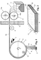
- FIG. 1 The apparatus shown is used to produce porous granules of Si0 2 , which are used in the process according to the invention as a hard template for the production of porous carbon.
- This device and the process for hard templating are described in DE 10 2011 014 875 B3 explained.
- the device comprises a drum 1 rotatable about its axis of rotation 2, which consists of a base made of stainless steel, which is covered with a thin layer of silicon carbide.
- the drum 1 has an outer diameter of 30 cm and a width of 50 cm.
- a layer 5 of SiO 2 -Soot is deposited and easily thermally densified to form a SiO 2 porous soot plate 5 a.
- Flammhydrolysebrenner 4 are used, four of which are arranged in a common row of burners 3 in the direction of the drum longitudinal axis 2 in a row.
- the burner row 3 is moved parallel to the axis of rotation 2 between two stationary inflection points back and forth.
- the flame hydrolysis burners 4 are fed as fuel gases oxygen and hydrogen and octamethylcyclotetrasiloxane (OMCTS) as a feedstock for the formation of SiO 2 particles.
- OCTS octamethylcyclotetrasiloxane
- the size of the SiO 2 primary particles produced in this process is in the nanometer range, with several primary particles coming together in the burner flame 6 and being in the form of more or less spherical aggregates having a BET specific surface area in the range of 25 m 2 / g, which is deposited on the drum Coat surface 1 a form a continuous, uniformly thick SiO 2 soot layer 5.
- the primary particles collect on their way to the deposition surface to nanoparticles together. Depending on the degree of interaction with the reaction zone on its way to the deposition surface, a different number of primary particles are combined, so that in principle results in a broad particle size distribution of the nanoparticles in the range of about 5 nm to about 200 nm.
- the nanoparticles are connected to each other via so-called sintering necks. Larger voids or pores are formed between the individual nanoparticles, forming a system of interconnected macropores in the soot layer and in sections of the nanoparticles.
- a certain thermal solidification of the soot layer is desired, so that a porous, coherent framework is formed in which spherical nanoparticles are aggregated or agglomerated into larger units and connected to one another via so-called "sintering necks".
- the rotational speed of the drum 1 and the deposition rate of the flame hydrolysis burners 4 are tuned so that a SiO 2 -Sootschic 5 with a width of about 40 cm and a thickness of about 45 microns results (the soot layer is in FIG. 1 for reasons of representation exaggerated thick drawn).
- the burners 4 at the same time bring about a certain pre-sintering of the soot layer 5 to a soot plate 5a by producing an average temperature of about 1200 ° C. on the surface of the topmost soot layer.
- the pre-sintering is supported by a tubular infrared radiator 14, which is formed within the hollow drum Drum 1 is arranged in the lower left quadrant, and heated the lateral surface of the drum 1 shortly after the application of the soot layer 5 from the inside.
- the thus obtained porous, slightly presintered soot plate 5a has an average specific gravity of about 22% (based on the density of quartz glass at 2.21 g / m 3 ).
- the soot plate 5a After a little more than half a turn of the drum, the soot plate 5a reaches the area of action of a blower 7, by means of which a gas flow directed against the underside of the soot plate 5a is generated, so that the soot plate 5a lifts off the drum jacket surface 1a.
- the soot plate 5a is then fed via a support roller 8 to a breaking tool 9, which consists of two counter-rotating rollers 10a, 10b, between which a gap with the thickness of the soot plate 5a is provided, and whose surfaces are provided with longitudinal profiles.
- the soot plate 5 a passing through the gap is divided by the longitudinal profiles of the rollers 10, 10 a into approximately equal sized fragments (granulate particles 13) which are collected in a collecting container 11.
- a partition wall 12 is provided, which is provided with an opening for the passage of the soot plate 5a and which serves to shield the Sootabscheidereaes of the effects of the crushing process.
- the granule particles 13 obtained by the process have a platelike or flake-like morphology and a thickness which corresponds approximately to the thickness of the soot plate 5a, ie about 45 ⁇ m.
- the granulate particles 13 are approximately the same size, so that sets a narrow particle size distribution.
- such a porous template is coated with soot structure with sulfur-containing active material, wherein the inner surfaces of the pores and cavities are coated with the active material, so that the predetermined in the template pore structure and particle distribution is more or less transferred to this coating.
- FIG. 2 schematically shows such a non-spherical, plate-like SiO 2 granules 13 according to the invention.
- the granulate particle 13 has a more or less planar upper side 23 and a lower side 21 running parallel thereto as well as lateral fracture surfaces 22, each with open pores.
- the thickness dimension is indicated by “c” and the two lateral dimensions by “a” and “b”.
- the structure ratio "A”, ie the ratio of the largest structure width (a) or (b) and thickness (c) of the granule particles 13 is about 10 in the exemplary embodiment.
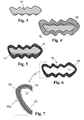
- porous granule particles thus produced serve as a hard template for the production of porous, flaky carbon powder, as shown in FIGS. 3 to 6 is shown schematically and will be explained in more detail below.
- the nonspherical platelet-shaped template particles 13 are composed of a multiplicity of spherical aggregates of SiO 2 primary particles which are connected to one another and thus form a "soot framework".
- a single such primary particle aggregate 16 is in FIG. 3 schematically shown, which thus shows a section of a "soot scaffold".
- the granules 16 are homogeneously mixed with finely ground mesophase pitch powder in a volume ratio of 1: 1 (pitch: granules) by means of a mixer. - The mixing time is about 5 min.
- the particle mixture is then heated to a temperature of 300 ° C.
- the low-viscosity pitch envelops the small SiO 2 primary particle aggregate 16 and penetrates into the pores and infiltrates them.
- the volume ratio of pitch and primary particle aggregate is chosen such that the pitch fills the pores so far that after an infiltration period of 30 minutes, hardly any appreciable free pore volume remains.
- FIG. 4 schematically shows the thus obtained composite of primary particle aggregate 16, surrounded by a pitch layer 15th
- the temperature is raised to 700 ° C under nitrogen and the pitch of the composite layer is reduced to carbon (carbonized).
- the original layer of pitch shrinks and then forms a graphite-like Carbon layer 19 with a slightly smaller thickness like FIG. 5 schematically shows.
- the carbon layer 19 has a low porosity and is on average about 50 nm thick. In the context, it should be noted that the representation of Figures 3 to 6 is not to scale.
- the SiO 2 of the primary particle aggregates 16 is then removed by placing the composite mass in a bath of 2 molar NaOH solution. Since the template particles consist of net-like nanoparticles, the NaOH solution can penetrate within the network structure until the entire template material is removed.
- FIG. 6 schematically shows the porous carbon structure 18 obtained after etching away the SiO 2 primary particle aggregate 16.
- the carbon structure 18 consists of a thin, graphite-like carbon layer 19 which forms the wall of a cavity 17, which was originally occupied by an SiO 2 nanoparticle agglomerate of a primary particle aggregate 16 -.
- the carbon structure 18 extends in all spatial directions and represents approximately a negative image of the mass distribution of the original SiO 2 primary particle aggregates 16. It has a hierarchical pore structure. It is important that the cavity 17 is not closed, but fluidly connected to other meso and macropores. It provides a free pore volume as well as further surface area over which an active material fixed to or in the carbon structure 18 is accessible to an electrolyte.
- the resulting composite structure 18 is further comminuted as needed. Carbon flakes are obtained in which a finely ragged surface of larger cavities is channel-like traversed.
- the manufacturing process is the subject of DE 10 2011 013 075 A1 ,
- the carbon fibrils of porous carbon with hierarchical pore structure thus produced are particularly suitable for the production of electrode layers of the sulfur electrode (cathode) of a rechargeable lithium-sulfur battery.
- the carbon flakes are infiltrated by means of a hydrothermal process with sulfur.
- the final temperature of the hydrothermal treatment is chosen so that it is sufficient to melt the sulfur, but is below the critical point of water. It forms a liquid phase containing sulfur melt and subcritical water and just covers the amount of carbon flakes. The liquid phase penetrates the pores of the carbon flakes under high pressure, so that they are loaded with sulfur.
- the solubility of sulfur in the aqueous phase is increased and the water exhibits an additional wetting effect by reducing the repulsion between the hydrophilic carbon surface and the hydrophobic sulfur melt.
- the risk of clogging of the narrow pore channels, which interconnect larger cavities (pores) formed in the porous carbon structure, is thus reduced.
- the initial amount of sulfur is chosen so that it is absorbed as completely as possible in the pores of the carbon structure, so that the proportion of Residual sulfur is as low as possible after the hydrothermal treatment.
- the floating sulfur is removed by flotation, and the residual solid content containing the carbon-sulfur composite is filtered off.
- FIG. 7 schematically shows.
- the walls of the carbon structure 19 are largely covered by a layer 20 of sulfur, including the inner walls of the cavities 17th
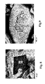
- FIG. 8 shows a scanning electron micrograph of a composite produced by melt infiltration of carbon and sulfur. Areas of carbon "K” are recognizable by the dark gray or black color. Surfaces of sulfur "S” are brightly colored. From this it is immediately apparent that the carbon regions and sulfur regions are strictly separated from each other, and there is no intimate connection. A large part of the sulfur S is deposited on the outside of the carbon particle K and does not infiltrate into the cavities.
- FIG. 9 a section of a composite prepared according to the invention.
- Sulfur S is homogeneously distributed in the carbon matrix.
- the dimensions of the composite powder correspond approximately to those of the raw material component (A).
- local element concentrations on the powder particles were determined by EDX analysis.
- a thin surface layer of a composite powder particle was sputtered by focused Ga ion beam.
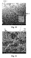
- FIG. 10 shows the corresponding gate of the composite powder particle.
- the original, non-sputtered surface of the particle is seen in the upper left corner of the image as a substantially white area. In this area the EDX analysis EDX1 was made.
- FIG. 11 shows the in FIG. 10 marked area in greater magnification. From this, several larger cavities 17 and a multiplicity of fine pore channels 17a can be seen.
- FIG. 11 shows plastically the tortuosity of the carbon structure, which causes a high retention capacity for the active material. In this area the EDX analysis EDX2 was made.
- Table 1 shows the result of the EDX1 analysis for the outer surface of the composite particle: ⁇ b> Table 1 ⁇ / b> element Wt .-% Atom-% C 74.08 89.68 S 5.21 9:55 ga 1.67 12:35 Ag 3.19 12:43 Total 100.00 100.00
- Table 2 shows the result of the EDX2 analysis for the inner walls in the area of the cavities 17 and pore channels 17a: ⁇ b> Table 2 ⁇ / b> element Wt .-% Atom-% C 22.76 45.07 S 71.35 52.93 ga 5.89 2:01 Total 100.00 100.00
- the comparison shows that the sulfur content in the region of the inner wall of the composite powder particles is more than 3 times higher than on the outside thereof.
- Table 2 also shows that the sulfur content on the inner wall of the cavities 17 and pore channels 17a is more than 3 times higher than the carbon content, which indicates an almost complete and dense coverage of the carbon walls.
Landscapes
- Chemical & Material Sciences (AREA)
- Chemical Kinetics & Catalysis (AREA)
- Electrochemistry (AREA)
- General Chemical & Material Sciences (AREA)
- Inorganic Chemistry (AREA)
- Engineering & Computer Science (AREA)
- Manufacturing & Machinery (AREA)
- Composite Materials (AREA)
- Materials Engineering (AREA)
- Battery Electrode And Active Subsutance (AREA)
- Carbon And Carbon Compounds (AREA)
Description
- Die vorliegende Erfindung betrifft ein Komposit aus porösem Kohlenstoff und Schwefel-haltigem Aktivmaterial, mit einer porösen Kohlenstoffstruktur, die eine Außenoberfläche und über Porenkanäle von der Außenoberfläche aus zugängliche und miteinander verbundene Kavitäten aufweist, die von Innenwandungen begrenzt sind. Weiterhin betrifft die Erfindung ein Verfahren für die Herstellung eines derartigen Komposits aus porösem Kohlenstoff und Schwefel-haltigem Aktivmaterial. Im Zuge der Entwicklung mobiler Energiespeicher steigt die Nachfrage nach wiederaufladbaren Batterien ("Akkumulatoren" oder "Sekundärbatterien"). Grundlegende Anforderung ist dabei eine hohe gravimetrische Energiedichte. Insbesondere für kommerzielle Anwendungen sollen die Elektrodenmaterialien preiswert, nicht toxisch, nicht explosiv und leicht zu verarbeiten sein.
- Weit verbreitet sind Lithium-Sekundärbatterien. Bei diesen sind eine Kathode (positive Elektrode) und eine Anode (negative Elektrode) aus einem Material vorgesehen, das zur Einlagerung und Auslagerung (Interkalation und Deinterkalation) von Lithiumionen geeignet ist, und das an einen Elektrolyten angrenzt, der die Bewegung der Lithiumionen zulässt. Als Anodenmaterial sind Kohlenstoffstrukturen im Einsatz, die Lithiumionen reversibel aufnehmen und abgeben können, ohne dass sich seine strukturellen und elektrischen Eigenschaften wesentlich ändern. Die Kathode der Lithium-Sekundärbatterien besteht hauptsächlich aus komplexem Oxid von Lithium und einem Übergangsmetall, wie etwa Lithiumcobaltoxid (LiCoO2) Die theoretische Zellspannung liegt um 3,7 V und die Energiedichte bei hohem Wirkungsgrad (um 90%) je nach Typ im Bereich von 120 bis 210 Wh/kg. Die theoretische maximale Kapazität ist auf etwa 300 mAh/g beschränkt. Lithium-Schwefel-Sekundärbatterien sind in der Entwicklung und gelten als eine der viel versprechenden Sekundärbatterien der nächsten Generation. In Ihrer ein-fachsten Konfiguration besteht die Zelle aus einer positiven Elektrode aus Schwefel und einer negativen Elektrode aus Lithium. Die theoretische Kapazität beträgt 1.650 mAh pro g Schwefel (unter der Annahme, dass alle Schwefelatome bei der Entladung einer Elektrode vollständig zu S2- reduziert werden), die Nennspannung liegt bei 2,2 V/Zelle und sie hat potenziell eine der höchsten Energiedichten aller Akkumulatoren überhaupt, nämlich um 2500 Wh/kg. Der in der Praxis bisher erzielbare Wirkungsgrad liegt jedoch deutlich darunter.
- Die an der Reaktion beteiligte Komponente Schwefel (oder schwefelhaltige organische Verbindungen) wirkt als elektrischer Isolator, so dass der Ablauf einer elektrochemischen Reaktion einen andauernden innigen Kontakt mit einer elektrisch gut leitfähigen Komponente - wie etwa Kohlenstoff - erfordert.
- Um die ionische Leitung der schwefelhaltigen Elektrode zu gewährleisten, werden flüssige Elektrolyte - häufig polare organische Lösungsmittel - eingesetzt. Diese dienen nicht nur als Ionentransportmedien zwischen Anode und Kathode, sondern auch als Ionenleiter innerhalb der schwefelhaltigen Elektrode. Dadurch ergibt sich einerseits die Problematik, dass die Elektrodenstruktur einen ungehinderten Zutritt des Elektrolyten ermöglichen soll. Zum anderen können sich Sulfid- und Polysulfid-Entladeprodukte wie Li2S2 oder Li2S in dem Elektrolyten lösen und von diesem ausgetragen werden. Dies gilt insbesondere dann, wenn große Reservoirs des Elektrolyten zur Verfügung stehen. Die von der Positivelektrode wegdiffundierten Schwefelkomponenten sind für die weitere elektrochemische Reaktion nicht mehr verfügbar, wodurch die Ladekapazität sinkt. Es ist auch möglich, dass Entladungsprodukte irreversibel aus der Elektrolytlösung ausfallen, wodurch die Ladekapazität ebenfalls sinkt.
- Zur Verringerung dieser nachteiligen Effekte wird in der
US 2009/0311604 A1 vorgeschlagen, das Wegdiffundieren der Schwefelbeladung aus der Kathode zu minimieren, indem als Gerüstmaterial für die Kathode eine poröse Kohlenstoffmatrix mit Nanoporen bereitgestellt wird, in denen die Schwefelbeladung absorbiert ist. Die Nanoporosität kann zwischen 10 und 99 % des Elektrodenmaterials ausmachen, wobei die Schwefelbeladung das Porenvolumen nicht vollständig ausfüllt, um ein Teilvolumen für den Zu- und Abfluss des flüssigen Elektrolyten freizulassen. - In die Nanoporen der Kohlenstoffmatrix wird Schwefelschmelze einfiltriert. Die Poren sind über Nanokanäle miteinander verbunden, welche die Mobilität des eingelagerten Schwefels sowie von Schwefel-Lithiumverbindungen, die sich beim Entladen in dem Elektrolyten lösen, begrenzen können. Diese verbleiben dadurch in unmittelbarer Nähe der Kohlenstoffmatrix und damit in Kontakt zum elektrischen Leiter, so dass über diesen die Umkehrung der elektrochemischen Reaktion beim Aufladen des Akkumulators ermöglicht wird. Als geeignete Ausgangskomponenten für die Kohlenstoffmatrix werden Aerogele, Xerogele und Molekularsiebe genannt.
- Eine Weiterentwicklung dieser Methode ist aus einer Publikation von Xiulei Ji, Kyu Tae Lee, Linda F. Nazar "A highly ordered nanostructured carbon-sulphur cathode for lithium-sulphur batteries" in Nature Materials 8, 500 - 506 (2009) bekannt. Dabei wird als Kohlenstoffmatrix ein unter der Bezeichnung "CMK-3" bekanntes, mesoporenhaltiges Kohlenstofferzeugnis eingesetzt, das eine geordnete Porenstruktur mit einheitlicher Porengröße und großem Porenvolumen aufweist. Dieses Kohlenstofferzeugnis wird mittels eines so genannten "Harttemplatverfahrens" erzeugt. Als Harttemplat wird "SBA-15" (abgeleitet von: "Santa Barbara Amorphous type material" (University of California)) eingesetzt, ein Siliziumdioxid-Erzeugnis mit periodischer und einstellbarer Anordnung von Mesoporen und sehr hoher spezifischer Oberfläche. Auf diese Weise wird eine geordnete Kohlenstoffstruktur erhalten, bei der parallel und in hexagonaler Anordnung verlaufende 6,5 nm dicke Kohlenstoff-Nanoröhrchen über 3-4 nm weite Kanäle voneinander getrennt sind. Die Kohlenstoff-Nanoröhrchen sind mittels Kohlenstoff-Mikrofasern, die die Kanäle überspannen, miteinander verstrebt, so dass ein Kollabieren der Struktur verhindert wird. Diese Kohlenstoffstruktur wird mit schmelzflüssigem Schwefel infiltriert, wobei der Schwefel durch Kapillarkräfte in die Kanäle eingezogen wird und nach dem Abkühlen Schwefel-Nanofasern mit Durchmessern um 3 nm bildet, die in innigem Kontakt mit der Kohlenstoffstruktur stehen.
- Ein ähnliches Verfahren zur Herstellung von Kohlenstoff-Schwefel-Kompositpulvers ist auch beschrieben im Paper "Porous carbon-sulfur composite cathode for lithium/sulfur cells" von Mumin Rao et al., veröfffentlicht am 12.01.2012 in: Electrochemistry Communications 17 (2012), Seiten 1-5. Dabei wird eine wasserlösliche schwefelhaltige Verbindung in Wasser gelöst und die Lösung mit Kohlenstoffpulver versetzt. Durch tropfenweises Titrieren in Ameisensäure wird ein Präzipitat erzeugt, das Kohlenstoffpartikel in Verbindung mit ausgefällten Schwefel-Nanopartikeln enthält. Dieser Feststoff wird gereinigt und getrocknet. Anschließend wird er 12 h lang auf 160 °C unter einem Ar-Gasstrom erhitzt. Dadurch wird der Schwefel flüssig, so dass er besser in die Mikroporen der Kohlenstoffpartikel eindringt, wobei gleichzeitig überflüssiger Schwefel von den Außenoberflächen der Kohlenstoffpartikel abdampfen soll. Der Schwefelanteil vermindert sich infolge dieser thermischen Behandlung von 69,8 Gew.-% auf 53,7 Gew.-%.
- Mittels Templatverfahren erzeugte, poröse Kohlenstoffstrukturen in ungeordneter und in geordneter Form sowie Verfahren für deren Herstellung sind auch beschrieben in der
DE 10 2011 013 075 beziehungsweise im Paper "Ordered Mesoporous Carbons" von Ryong Ryoo et al., veröffentlicht in Adv. Mater. 2001, 13 (9), S. 677-681 Weiterhin offenbartUS2011/0052998 ein Verfahren für die Herstellung eines Komposits aus porösem Kohlenstoff und Schwefel als Aktivmaterial. - Das Verfahren ist aufwändig und teuer. Darüber hinaus zeigt es sich, dass die Schmelzinfiltration von Schwefel in eine Matrix von porösem Kohlenstoff stark von der Oberflächenpolarität des verwendeten Kohlenstoffs abhängt und dass abstoßende Wechselwirkungen zwischen dem eher hydrophilen Kohlenstoff und der hydrophoben Schwefelschmelze die Infiltration behindern.
- Erschwerend trägt die Eigenschaft von schmelzflüssigem Schwefel bei, zu Polymerisation zu neigen. Polymerisate können die engen Porenkanäle und damit die Zugänge zu den Poren leicht verstopfen und damit zu belegungsfreiem Totvolumen innerhalb der Poren führen.
- Demzufolge wird mittels der bekannten Methoden eine Kohlenstoffstruktur mit inhomogener Schwefelbeladung erhalten, bei der die Konzentration des Schwefels auf den von außen leicht zugänglichen freien Oberflächen wesentlich höher ist, als auf den Oberflächen an der Innenwandung der Poren.
- Um eine hohe Ladekapazität der Schwefelelektrode zu erreichen, ist daher nicht nur das Bereitstellen einer Kohlenstoffstruktur mit optimaler, das heißt möglichst hierarchischer Porenverteilung erforderlich, sondern auch eine optimale Verteilung des Schwefels in den Poren.
- Außerdem treten in der Schwefel-Elektrode beim Aufladevorgang Polysulfide auf, die im Elektrolyten löslich sind, was die Rückhaltung innerhalb der porösen Kohlenstoff-Elektrodenstruktur erschwert.
- Der Erfindung liegt daher die Aufgabe zugrunde, ein Komposit aus einer porösen Kohlenstoffstruktur und Schwefel anzugeben, das sich beim Einsatz als Elektrodenmaterial für eine Lithium-Schwefel-Sekundärbatterie durch hohe Kapazität und einen geringen Kapazitätsverlust auszeichnet.
- Außerdem liegt der Erfindung die Aufgabe zugrunde, ein Verfahren anzugeben, das eine kostengünstige Herstellung eines derartigen Kompositpulvers ermöglicht.
- Diese Aufgabe wird erfindungsgemäß durch ein Verfahren gelöst, das folgende Verfahrensschritte umfasst:
- (a) Bereitstellen von Pulver aus porösem Kohlenstoff,
- (b) Herstellen einer Dispersion aus dem Kohlenstoff-Pulver, dem Schwefelhaltigen Aktivmaterial und einem wässrigen Medium,
- (c) Hydrothermale Behandlung der Dispersion bei einer Temperatur, die zum Aufschmelzen von Schwefel ausreicht, unter Bildung einer Flüssigphase, die Schwefelschmelze und Wasser enthält, und Infiltrieren von Poren des porösen Kohlenstoffs mit der Flüssigphase,
- (d) Entfernen des Wassers und Isolieren des Komposits.
- Es wird eine Dispersion erzeugt, bei der in einem wässrigen Medium, wie Wasser, Säure oder Lauge mit etwaigen Zusatzstoffen, partikelförmiger Feststoff möglichst homogen verteilt ist. Der Feststoff umfasst Pulver aus porösem Kohlenstoff und Aktivmaterial. Das Aktivmaterial enthält Schwefel oder eine schmelzbare Schwefelverbindung. Die Dispersion wird einer hydrothermalen Behandlung unterzogen. Diese erfolgt unter Druck und erhöhter Temperatur in einem druckfesten Behälter, wie etwa einem Autoklaven. Beim Erhitzen verdampft ein Teil des Wassers und übt einen Druck innerhalb des Behälters aus.
- Für die vorliegende Erfindung wesentlich ist das Vorliegen einer Flüssigphase, die eine unabhängige Schwefelphase in einer flüssigen Wasserphase bei hoher Temperatur oberhalb von 100 °C und hohem Druck enthält.
- Daher ist die Temperatur bei der hydrothermalen Behandlung einerseits hoch genug, um Schwefel oder die Schwefelverbindung aufzuschmelzen. Schwefel kommt in mehreren Modifikationen vor. Im thermodynamischen Gleichgewicht liegt die minimale Schmelztemperatur bei 119,6 °C (für reinen β-Schwefel mit monokliner Kristallstruktur bei einem Druck von 0,018 mbar); in rhomboedrischer Kristallstruktur (α-Schwefel) kann die Schmelze bei Normaldruck kinetisch bedingt auch bereits bei niedrigerer Temperatur einsetzen; in der Literatur werden für den Schmelzpunkt für Schwefel häufig Temperaturwerte um 115 °C genannt.
- Damit Wasser in flüssiger Form in der Flüssigphase verbleiben kann, liegt die Temperatur bei der hydrothermalen Behandlung andererseits unterhalb des sogenannten "kritischen Punktes". Im thermodynamischen Gleichgewicht liegt dieser Punkt bei einer Temperatur von 374,12 °C und bei einem Druck von 221,2 MPa.
- Diese Ortung der Eckpunkte von Temperatur und Druck der hydrothermalen Behandlung ergibt sich bei rein thermodynamischer Betrachtung. Bei Berücksichtigung kinetischer Aspekte können sich davon abweichende Grenzwerte für Temperatur und Druck ergeben.
- Durch Erhitzen von Wasser unter Druck auf Temperaturen oberhalb von 100 °C ändern sich dessen Eigenschaften. Unter hydrothermalen Bedingungen entfaltet das Wassermolekül eine höhere Nukleophilie, was die sonst in der Wasserchemie bekannten Anlagerungs- und Hydratisierungsreaktionen verändert. So hat es sich gezeigt, dass durch die hydrothermale Verfahrensführung das unterkritische flüssige Wasser als Netzmittel dient, indem es die Abstoßung zwischen der hydrophilen Kohlenstoffoberfläche und der hydrophoben Schwefelschmelze verringert. Darüber hinaus wird die Löslichkeit von Schwefel in der wässrigen Phase wesentlich erhöht, was darauf zurückgeführt werden kann, dass neben cyclo-Oktaschwefel auch Polysulfide entstehen.
- Diese Effekte können das Eindringen der Flüssigphase in die Poren der porösen Kohlenstoffstruktur erleichtern und das Auftreten von Verstopfungen vermindern, die etwa durch Schwefel-Polymerisat verursacht werden können. Es ergibt sich jedenfalls im Vergleich zu der aus dem Stand der Technik üblichen Schmelzinfiltration des Schwefels eine merklich homogenere Verteilung des Schwefel-haltigen Aktivmaterials in den Poren der Kohlenstoff-Partikel.
- Nach Abschluss der hydrothermalen Behandlung wird eine Dispersion aus dem wässrigen Medium, und Kohlenstoff-Schwefel-Pulverteilchen erhalten. Diese werden anhand üblicher Methoden separiert, so dass ein Kompositpulver aus porösem Kohlenstoff und darin homogen und in großer Menge eingelagertem Aktivmaterial erhalten wird.
- Das erfindungsgemäße Verfahren stellt somit eine kostengünstige Maßnahme dar, die ein homogenes Infiltrieren von porösem Kohlenstoff mit Schwefel enthaltendem Aktivmaterial ermöglicht und das die oben beschriebenen Nachteile der bekannten Methoden vermeidet.
- Bei der hydrothermalen Behandlung liegt die gewünschte Flüssigphase, die eine unabhängige Schwefelphase in einer flüssigen Wasserphase enthält, vorzugsweise in einer Menge vor, die ausreicht, die Menge an porösem Kohlenstoff zu bedecken.
- So wird eine gleichmäßige Beladung der gesamten Menge an porösem Kohlenstoff gewährleistet. Der Druck innerhalb des Druckbehälters stellt sich dabei in Abhängigkeit von der vorgegebenen Temperatur entsprechend dem Wasser-Partialdruck automatisch ein.
- Im Hinblick darauf hat sich auch bewährt, wenn das Gewichtsverhältnis von wässrigem Medium und Feststoffphase in der Dispersion zwischen 0,5:1 und 3:1 liegt.
- Der Feststoffanteil ergibt sich dabei aus dem porösen Kohlenstoff und dem Aktivmaterial. Bei einem Anteil des wässrigen Mediums höher als 3:1 kommt es zunehmend zu Entmischungserscheinungen. Bei einem Anteil des wässrigen Mediums von weniger als 0,5:1 verliert sich dessen benetzende und verflüssigende Wirkung, was ein homogenes Befüllen der Poren der Kohlenstoffstruktur erschwert.
- Die Dauer der hydrothermalen Behandlung richtet sich nach dem gewünschten Grad der Beladung des porösen Kohlenstoffs mit dem Aktivmaterial und sie hängt von der Viskosität der Flüssigphase, der Füllmenge an Aktivmaterial und der Teilchengröße des Kohlenstoff-Pulvers ab. Typischerweise beträgt die Dauer der hydrothermalen Behandlung mindestens 180 min.
- Theoretisch nimmt die Kapazität des Komposits mit dem Gewichtsanteil an Aktivmaterial zu, aber auch die dem Aktivmaterial verbundene Volumenänderung beim Entlade- und Ladevorgang, wie oben bereits erläutert. Die Kohlenstoffmatrix des Kompositpulvers dient zur Schaffung eines Gerüstes oder einer Umhüllung und zur Abpufferung von Volumenänderungen. Im Fall des erfindungsgemäßen Komposits hat sich ein Gewichtsanteil von 1 bis 90 %, vorzugsweise zwischen 50 und 80 % für das Aktivmaterial als günstig erwiesen.
- Das Isolieren des Komposits nach Abschluss der hydrothermalen Behandlung umfasst bevorzugt einen Flotationsschritt.
- Nach Abschluss der hydrothermalen Behandlung wird eine Dispersion erhalten, bei der etwaiger Restschwefel aufschwimmt und so durch Flotation abgezogen werden kann. Das vergleichsweise schwerere Komposit sinkt hingegen nach unten ab.
- Bei einer besonders bevorzugten Verfahrensvariante umfasst das Bereitstellen des Kohlenstoff-Pulvers ein Templatverfahren, bei dem ein Kohlenstoffgerüst um ein strukturdirigierendes Templat aus porösem SiO2-Soot aufgebaut und das Templatmaterial daraufhin entfernt wird.
- Ein derartiges Templat-Verfahren zur Herstellung eines porösen Kohlenstofferzeugnisses für Elektroden von Sekundärbatterien ist an und für sich aus der
DE 10 2010 005 954 A1 bekannt. Dabei wird durch Hydrolyse oder Pyrolyse einer siliziumhaltigen Ausgangsverbindung mittels eines Sootabscheideprozesses zunächst ein poröses SiO2-Templ aus agglomerierten oder aggregierten SiO2-Nanopartikeln erzeugt. Die Poren werden mit einer Kohlenstoff-Vorläufersubstanz infiltriert. Nach dem Kalzinieren wird das SiO2-Templ durch Ätzen entfernt. Es wird ein poröses Kohlenstofferzeugnis mit hierarchischer Porenstruktur erhalten, das für die Durchführung des erfindungsgemäßen Verfahrens optimal geeignet ist. - Je feinteiliger die Templat-Partikel sind, umso schneller, effektiver und gleichmäßiger erfolgt die Infiltration mit Kohlenstoff bei ansonsten gleichen Prozessbedingungen. Die Templat-Partikel werden beispielsweise durch Aufmahlen poröser SiO2-Sootkörpe oder durch Brechen von Schichten aus SiO2-Soot, durch Pressen eines Pulvers aus SiO2-Soot oder Granulationsverfahren hergestellt. Vorzugsweise wird das Templat in Form poröser SiO2-Granulatteilchn mit nicht sphärischer Morphologie bereitgestellt, die erhalten werden, indem eine durch Gasphasenabscheidung erzeugte SiO2-Sootschicht thermisch zu einer porösen Sootplatte verfestigt und danach zu den porösen Granulatteilchen zerkleinert wird.
- Die durch Sootabscheidung erzeugte und thermisch verdichtete Sootplatte kann mit geringem Aufwand zerkleinert werden, wobei Granulatteilchen mit plättchenartiger oder flockenartigen Morphologie erhalten werden. Diese zeichnen sich somit durch eine nicht sphärische Morphologie aus, die besonders homogen und schnell mit Kohlenstoff infiltriert werden kann, denn die Granulatteilchen zeigen ein großes Verhältnis von Oberfläche zu Volumen, was die Infiltration mit einer flüssigen Substanz vereinfacht und vergleichmäßigt.
- Bei einer bevorzugten Methode zum Aufbau des Kohlenstoffgerüsts wird eine Mischung aus Templat-Partikeln und aus Partikeln einer schmelzbaren Vorläufersubstanz für Kohlenstoff erhitzt, so dass Vorläufersubstanz-Schmelze in die Poren der Templat-Partikel eindringt und die Vorläufersubstanz vor dem Entfernen des Templatmaterials carbonisiert wird.
- Dabei wird die Vorläufersubstanz für Kohlenstoff in Kontakt mit dem Templat erhitzt und dabei erweicht oder erschmolzen, so dass sie in die Poren des Templats eindringen kann. Auf ein Lösungsmittel für die Kohlenstoff-Vorläufersubstanz kann verzichtet werden. Diese "direkte Infiltration" des Templats mit verflüssigter Vorläufersubstanz gelingt am besten, wenn vorab erzeugte Pulver sowohl aus dem porösen Templatmaterial als auch von der Vorläufersubstanz bereitgestellt, diese Pulver homogen miteinander vermischt und die homogene Pulvermischung so weit erhitzt, dass die Partikel der Vorläufersubstanz schmelzen. Diese Schmelze kann in die benachbarten Templat-Partikel unmittelbar eindringen. Die homogene Pulvermischung gewährleistet, dass stets schmelzflüssige Vorläufersubstanz im innigen Kontakt mit den Templat-Partikeln steht, so dass sich eine gleichmäßige Verteilung und Belegung über das gesamte zu infiltrierende Poren-Volumen des Templatmaterials ergibt. Die hohe Temperatur beim Erschmelzen der Vorläufersubstanz trägt zur besseren Benetzbarkeit der Oberflächen des Templats bei, so dass sich ein auch bei nur einmaliger Infiltration bereits ein hoher Füllgrad des Porenvolumens einstellt. Nach dem Carbonisieren wird das anorganische Templatmaterial entfernt. Dieses dient lediglich als mechanisch und thermisch stabiles Gerüst zum Ablagern und Calzinieren der Kohlenstoff-Vorläufersubstanz.
- Das Kohlenstofferzeugnis fällt bei den oben beschriebenen Templat-Herstellungsmethoden in der Regel als Monolith mit plättchen- oder flockenartiger Morphologie an. Das daraus erzeugte Kompositpulver liegt vorzugsweise in Form poröser Kohlenstoffflocken aus Kohlenstoffschichten mit einer mittleren Schichtdicke im Bereich von 10 µm bis 500 µm, vorzugsweise im Bereich von 20 µm bis 100 µm, besonders bevorzugt von weniger als 50 µm vor, die eine hierarchische Porenstruktur aufweisen.
- Schichtdicken von weniger als 10 µm können zu einer geringen mechanischen Stabilität der Kohlenstoffflocken führen. Kohlenstoffflocken mit einer Dicke von mehr als 500 µm sind über ihre Dicke zunehmend inhomogener. Die hierarchische Porenstruktur stellt sich infolge der oben näher erläuterten Herstellung eines SiO2-Soot-Templats durch Gasphasenabscheidung ein, und eignet sich besonders gut für die Herstellung der Elektroden aufladbarer Lithium-Schwefel-Batterien.
- Die hydrothermale Behandlung bewirkt innerhalb der Poren der porösen Kohlenstoffstruktur eine deutlich stärkere Beladung mit Aktivmaterial als außerhalb der Poren. Nur der innerhalb der Poren gelagerte Anteil des Aktivmaterials unterliegt dem Rückhaltevermögen der Kohlenstoffstruktur. Der an der Außenwandung abgelagerte Anteil kann hingegen ohne weiteres vom Elektrolyten abtransportiert werden und ist dann für den elektrochemischen Prozess verloren. Dies gilt insbesondere für Polysulfide, die typischerweise in Elektrolyten löslich sind.
- Daher ist vorzugsweise vorgesehen, dass der in Atom-% an der Oberfläche innerhalb der Poren des Kohlenstoffs gemessene Anteil des Aktivmaterial ist mindestens um den Faktor 1,5, vorzugsweise mindestens um den Faktor 3 höher als der an der Oberfläche außerhalb der Poren des Kohlenstoffs gemessene Anteil des Aktivmaterials.
- Hinsichtlich des Kohlenstoff und Schwefel enthaltenden Komposits wird die oben angegebene Aufgabe ausgehend von einem Komposit der eingangs genannten Gattung erfindungsgemäß dadurch gelöst, dass der in Atom-% gemessene Anteil des Aktivmaterials in den Porenkanälen und den Innenwandungen um mindestens den Faktor 1,5 höher ist als der an der Außenoberfläche, und dass in den Porenkanälen und den Innenwandungen der mittels EDX-Analyse in Atom-% ermittelte Anteil des Aktivmaterials um mindestens den Faktor 1,5 höher ist als der mittels EDX-Analyse in Atom-% ermittelte Anteil an Kohlenstoff.
- Der erfindungsgemäße Komposit wird beispielsweise anhand des erfindungsgemäßen Verfahrens erhalten. Wie im Zusammenhang mit diesem Verfahren erläutert, führt die hydrothermale Behandlung unter Anwesenheit einer Flüssigphase von wässrigem Medium und flüssigem Schwefel zu einer ausgeprägten und homogenen Beladung der Poren und Porenkanäle der porösen Kohlenstoffstruktur mit Schwefel. Die Beladungsmenge ist deutlich größer als sie mit bekannten Methoden erreichbar ist. Nur dadurch gelingt es überhaupt, an der Innenwandung von Poren und Porenkanälen eine Belegung mit Aktivmaterial, insbesondere mit Schwefel, zu erreichen, die bei Ermittlung mittels EDX-Analyse um mindestens den Faktor 1,5, vorzugsweise mindestens den Faktor 3 größer ist als der Anteil an Kohlenstoff (in Atom-%) und die gleichzeitig um mindestens den Faktor 1,5, vorzugsweise mindestens den Faktor 3 größer ist als der Anteil an Aktivmaterial an den Außenoberfläche.
- Der an der Außenoberfläche der Kohlenstoffstruktur abgelagerte Anteil an Aktivmaterial kann ohne weiteres vom Elektrolyten abtransportiert werden und ist dann für den elektrochemischen Prozess verloren. Nur der innerhalb der Poren und der Porenkanäle gelagerte Anteil des Aktivmaterials unterliegt dem Rückhaltevermögen der Kohlenstoffstruktur.
- Nachfolgend wird die Erfindung anhand eines Ausführungsbeispiels und einer Zeichnung näher erläutert. Im Einzelnen zeigt
- Figur 1
- eine Vorrichtung zur Herstellung von SiO2-Granulatteilchen als Templatmaterial zur Herstellung von porösem Kohlenstoff in schematischer Darstellung,
- Figur 2
- ein plättchenartiges SiO2-Granulatteilchen in schematischer Darstellung,
- Figuren 3 bis 6
- Stufen der Herstellung eines porösen Kohlenstofferzeugnisses in schematischer Darstellung,
- Figur 7
- den Ausschnitt A des Kohlenstofferzeugnisses gemäß
Figur 6 in vergrößerter Darstellung nach dem Beladen mit Aktivmaterial, - Figur 8
- eine rasterelektronenmikroskopische Aufnahme eines gemäß der Erfindung hergestellten Komposits aus Kohlenstoff und Schwefel,
- Figur 9
- eine rasterelektronenmikroskopische Aufnahme eines durch SchmelzInfiltration hergestellten Komposits aus Kohlenstoff und Schwefel zum Vergleich,
- Figur 10
- eine rasterelektronenmikroskopische Aufnahme eines erfindungsgemäßen Komposits im Anschnitt nach dem Absputtern mittels eines fokussierten lonenstrahls (Focused Ion Beam), und
- Figur 11
- den in
Figur 10 markierten Ausschnitt in stärkerer Vergrößerung zwecks Erläuterung des Messortes für eine EDX-Analyse - Die in
Figur 1 dargestellte Vorrichtung dient zur Herstellung poröser Granulatteilchen aus Si02, die beim erfindungsgemäßen Verfahren als Harttemplat zur Herstellung von porösem Kohlenstoff eingesetzt werden. Diese Vorrichtung und das Verfahren zur Harttemplat-Herstellung sind in derDE 10 2011 014 875 B3 erläutert. - Die Vorrichtung umfasst eine um ihre Rotationsachse 2 rotierbare Trommel 1, die aus einem Grundkörper aus Edelstahl besteht, der mit einer dünnen Schicht aus Siliciumcarbid belegt ist. Die Trommel 1 hat einen Außendurchmesser von 30 cm und eine Breite von 50 cm. Auf der Mantelfläche 1a der Trommel 1 wird eine Schicht 5 aus SiO2-Soot abgeschieden und unmittelbar zu einer SiO2-porösen Sootplatte 5a leicht thermisch verdichtet.
- Für die Sootabscheidung werden Flammhydrolysebrenner 4 eingesetzt, von denen vier in einer gemeinsamen Brennerreihe 3 in Richtung der Trommel-Längsachse 2 hintereinander angeordnet sind. Die Brennerreihe 3 wird parallel zur Rotationsachse 2 zwischen zwei ortsfesten Wendepunkten hin- und her bewegt. Den Flammhydrolysebrennern 4 werden als Brenngase Sauerstoff und Wasserstoff sowie Octamethylcyclotetrasiloxan (OMCTS) als Einsatzmaterial für die Bildung von SiO2-Partikeln zugeführt. Die Größe der dabei erzeugten SiO2-Primärpartikel liegt im Nanometerbereich, wobei sich mehrere Primärpartikel in der Brennerflamme 6 zusammenlagern und in Form mehr oder weniger sphärischer Aggregate mit einer spezifischen Oberfläche nach BET im Bereich von 25 m2/g anfallen, die auf der Trommel-Mantelfläche 1 a eine durchgängige, gleichmäßig dicke SiO2-Sootschicht 5 bilden.
- Die Primärpartikel lagern sich auf ihrem Weg zur Ablagerungsfläche zu Nanoteilchen zusammen. Je nach Grad der Wechselwirkung mit der Reaktionszone auf ihrem Weg zur Ablagerungsfläche lagert sich eine unterschiedliche Anzahl von Primärpartikeln zusammen, so dass grundsätzlich eine breite Teilchengrößenverteilung der Nanoteilchen im Bereich von etwa 5 nm bis etwa 200 nm ergibt. Die Nanoteilchen sind über sogenannte Sinterhälse miteinander verbunden. Zwischen den einzelnen Nanoteilchen ergeben sich größere Hohlräume oder Poren, die in der Sootschicht und in Teilstücken derselben ein System miteinander verbundener Makroporen bilden. Eine gewisse thermische Verfestigung der Sootschicht ist erwünscht, so dass ein poröses, zusammenhängendes Gerüst gebildet wird, in dem sphärische Nanoteilchen zu größeren Einheiten aggregiert oder agglomeriert und über sogenannte "Sinterhälse" miteinander verbunden sind.
- Die Rotationsgeschwindigkeit der Trommel 1 und die Abscheiderate der Flammhydrolysebrenner 4 sind so abgestimmt, dass sich eine SiO2-Sootschic 5 mit einer Breite von etwa 40 cm und einer Dicke von etwa 45 µm ergibt (die Sootschicht ist in
Figur 1 aus Darstellungsgründen übertrieben dick eingezeichnet). Die Brenner 4 bewirken gleichzeitig ein gewisses Vorsintern der Sootschicht 5 zu einer Sootplatte 5a, indem sie auf der Oberfläche der obersten Sootlage eine mittlere Temperatur von etwa 1200°C erzeugt. Unterstützt wird das Vorsintern von einem rohrförmigen Infrarotstrahler 14, der innerhalb der als Hohltrommel ausgebildeten Trommel 1 im linken unteren Quadranten angeordnet ist, und der die Mantelfläche der Trommel 1 kurz nach dem Aufbringen der Sootschicht 5 von der Innenseite aus erhitzt. - Die so erhaltene poröse, leicht vorgesinterte Sootplatte 5a hat eine mittlere relative Dichte von etwa 22 % (bezogen auf die Dichte von Quarzglas mit 2,21 g/m3).
- Nach etwas mehr als einer halben Trommel-Umdrehung gelangt die Sootplatte 5a in den Einwirkungsbereich eines Gebläses 7, mittels dem ein gegen die Unterseite der Sootplatte 5a gerichteter Gasstrom erzeugt wird, so dass sich die Sootplatte 5a von der Trommel-Mantelfläche 1 a abhebt.
- Die Sootplatte 5a wird anschließend über eine Stützrolle 8 einem Brechwerkzeug 9 zugeführt, das aus zwei gegensinnig rotierenden Rollen 10a, 10b besteht, zwischen denen ein Spalt mit der Dicke der Sootplatte 5a vorgesehen ist, und deren Oberflächen mit Längsprofilen versehen sind.
- Die durch den Spalt hindurchlaufende Sootplatte 5a wird durch die Längsprofile der Rollen 10, 10a in ungefähr gleich große Bruchstücke (Granulatteilchen 13) zerteilt, die in einem Auffangbehälter 11 gesammelt werden.
- Zwischen der Trommel 1 und dem Brechwerkzeug 9 ist eine Trennwand 12 vorgesehen, die mit einer Öffnung zur Durchführung der Sootplatte 5a versehen ist und die zur Abschirmung des Sootabscheideprozesses von den Auswirkungen des Zerkleinerungsprozesses dient.
- Die nach dem Verfahren erhaltenen Granulatteilchen 13 haben eine plättchenartige oder flockenartige Morphologie und eine Dicke, die in etwa der Dicke der Sootplatte 5a entspricht, also etwa 45 µm. Infolge des beschriebenen Brechvorgangs sind auch die Granulatteilchen 13 in etwa gleich groß, so dass sich eine enge Korngrößenverteilung einstellt.
- Für die Herstellung des erfindungsgemäßen Komposits wird ein derartiges poröses Templat mit Sootstruktur mit schwefelhaltigem Aktivmaterial beschichtet, wobei die inneren Oberflächen der Poren und Hohlräume mit dem Aktivmaterial belegt werden, so dass die im Templat vorgegebene Porenstruktur und Teilchenverteilung mehr oder weniger auf diese Beschichtung überführt wird.
-
Figur 2 zeigt schematisch ein derartiges nicht sphärisches, plättchenartiges SiO2-Granulatteilchen 13 gemäß der Erfindung. Das Granulatteilchen 13 hat eine mehr oder weniger plane Oberseite 23 und eine parallel dazu verlaufende Unterseite 21 sowie seitliche Bruchflächen 22, jeweils mit offenen Poren. Die Dickenabmessung ist mit "c" bezeichnet und die beiden seitlichen Abmessungen mit "a" und "b". Das Strukturverhältnis "A", also das Verhältnis von größter Strukturbreite (a) oder (b) und Dicke (c) der Granulatteilchen 13 beträgt im Ausführungsbeispiel etwa 10. - Die so erzeugten porösen Granulatteilchen dienen als Harttemplat für die Herstellung von porösem, flockenförmigem Kohlenstoffpulver, wie dies in
Figuren 3 bis 6 schematisch dargestellt ist und im Folgenden näher erläutert wird. - Die nicht sphärischen, plättchenförmigen Templat-Partikel 13 setzen sich mikroskopisch betrachtet aus einer Vielzahl sphärischer Aggregate aus SiO2-Primärpartikeln zusammen, die miteinander verbunden sind und so ein "Soot-Gerüst" bilden. Ein einziges derartiges Primärpartikel-Aggregat 16 ist in
Figur 3 schematisch dargestellt, die also einen Ausschnitt aus einem "Soot-Gerüst" zeigt. Die Granulatteilchen 16 werden mit fein gemahlenem Pulver aus Mesophasenpech im Volumenverhältnis 1:1 (Pech : Granulatteilchen) mittels Mischer homogen miteinander vermischt. - Die Mischdauer beträgt etwa 5 min. - Die Partikelmischung wird anschließend auf eine Temperatur von 300°C erhitzt. Das niedrig viskose Pech umhüllt dabei die kleinen SiO2-Primärpartikel-Aggregat 16 und dringt in die Poren ein und infiltriert diese. Das Volumenverhältnis von Pech und Primärpartikel-Aggregat ist dabei so gewählt, dass das Pech die Poren soweit füllt, dass nach einer Infiltrationsdauer von 30 min kaum noch ein nennenswertes freies Porenvolumen übrig bleibt.
-
Figur 4 zeigt schematisch den so erhaltenen Verbund aus Primärpartikel-Aggregat 16, umhüllt von einer Pechschicht 15. - Nach der Infiltrationsdauer von 30 min wird die Temperatur auf 700 °C unter Stickstoff erhöht und das Pech der Kompositschicht zu Kohlenstoff reduziert (carbonisiert). Die ursprüngliche Pechschicht schrumpft dabei und bildet danach eine grafitähnliche Kohlenstoffschicht 19 mit etwas geringerer Dicke wie
Figur 5 schematisch zeigt. - Die Kohlenstoffschicht 19 hat eine geringe Porosität und sie ist im Mittel etwa 50 nm dick. In dem Zusammenhang ist anzumerken ist, dass die Darstellung der Figuren 3 bis 6 nicht maßstabsgetreu ist.
- Nach dem Abkühlen wird eine leicht poröse Kompositmasse aus nicht sphärischen porösen Primärpartikel-Aggregaten 16, erhalten, die überall mit einer Lage aus graphitisierbarem Kohlenstoff belegt sind.
- Das SiO2 der Primärpartikel-Aggregate 16 wird anschließend entfernt, indem die Kompositmasse in ein Bad aus 2-molarer NaOH-Lösung eingebracht wird. Da die Templat-Partikel aus netzartig miteinander verbundenen Nanopartikeln bestehen, kann die NaOH-Lösung innerhalb der Netzstruktur vordringen bis das gesamte Templatmaterial entfernt ist.
-
Figur 6 zeigt schematisch die nach dem Wegätzen des SiO2-Primärpartike Aggregats 16 erhaltene poröse Kohlenstoffstruktur 18. Durch das Entfernen des Templatmaterials bildet das Volumen, das vorher von sphärischen Nanoteilchen und deren Aggregaten/Agglomeraten belegt war Kavitäten 17, die über Porenkanäle - das sind die ehemaligen Sinterhälse - miteinander verbunden sind. - Die Kohlenstoffstruktur 18 besteht aus einer dünnen, grafitähnlichen Kohlenstoffschicht 19, welche die Wandung einer Kavität 17 bildet, die ursprünglichen von einem SiO2-Nanoteilchenagglomerat also von einem Primärpartikel-Aggregat 16 - besetzt war.
- Die Kohlenstoffstruktur 18 erstreckt sich in allen Raumrichtungen und stellt näherungsweise ein negatives Abbild der Massenverteilung der ursprünglichen SiO2-Primärpartikel-Aggregate 16 dar. Sie weist eine hierarchische Porenstruktur auf. Wichtig ist, dass die Kavität 17 nicht abgeschlossen, sondern mit anderen Meso- und Makroporen fluidisch verbunden ist. Sie stellt ein freies Porenvolumen sowie weitere Oberfläche zur Verfügung, über die ein an oder in der Kohlenstoffstruktur 18 fixiertes Aktivmaterial einem Elektrolyten zugänglich ist.
- Die so erhaltene Kompositstruktur 18 wird bei Bedarf weiter zerkleinert. Es werden Kohlenstoffflocken erhalten, bei denen eine feingliedrig zerklüftete Oberfläche von größeren Hohlräumen kanalartig durchzogen ist.
- Das Herstellungsverfahren ist Gegenstand der
DE 10 2011 013 075 A1 . - Die so erzeugten Kohlenstoffflocken aus porösem Kohlenstoff mit hierarchischer Porenstruktur eignen sich besonders gut für die Herstellung von Elektrodenschichten der Schwefelelektrode (Kathode) einer aufladbaren Lithium-Schwefel-Batterie. Hierzu werden die Kohlenstoffflocken anhand eines hydrothermalen Verfahrens mit Schwefel infiltriert.
- Als Ausgangskomponenten werden eingesetzt:
- (A) Poröse Kohlenstoffflocken mit seitlichen Abmessungen, die durch eine mittlere Dicke von 50 µm bei einem Strukturverhältnis von 5 gekennzeichnet sind. Diese haben eine Porosität, wie anhand
Figur 6 erläutert. - (B) Pulver aus reinem Schwefel in rhomboedrischer Modifikation mit einer Teilchengröße von weniger als 200 µm.
- (C) Deionisiertes Wasser mit einer Leitfähigkeit von weniger als 3 µS.
- Diese Komponenten werden in folgender Rezeptur eingesetzt:
Rezeptur 1: Kohlenstoffflocken: 200 g Schwefelpulver 160 g Wasser 150 g - Diese beiden Feststoff-Komponenten (A) und (B) werden im trockenen Zustand miteinander vermischt und mit deionisiertem Wasser homogen dispergiert; der Feststoffgehalt der Dispersion beträgt 70 Gew.-%. Sie wird in einen teflonbeschichteten Autoklaven eingebracht und darin folgender Prozedur unterzogen:
Prozedur 1: Aufheizrate 10 °C/min Endtemperatur 140 °C Haltedauer 360 min bei der Endtemperatur - Die Endtemperatur der hydrothermalen Behandlung ist dabei so gewählt, dass sie zum Aufschmelzen des Schwefels ausreicht, jedoch unterhalb des kritischen Punktes von Wasser liegt. Es bildet sich eine Flüssigphase, die Schwefelschmelze und unterkritisches Wasser enthält und die Menge an Kohlenstoffflocken gerade überdeckt. Die Flüssigphase penetriert die Poren der Kohlenstoffflocken unter hohem Druck, so dass diese mit Schwefel beladen werden.
- Unter den hydrothermalen Bedingungen wird die Löslichkeit von Schwefel in der wässrigen Phase erhöht und das Wasser entfaltet eine zusätzliche Wirkung als Netzmittel, indem es die Abstoßung zwischen der hydrophilen Kohlenstoffoberfläche und der hydrophoben Schwefelschmelze verringert. Die Gefahr von Verstopfungen der engen Porenkanäle, welche in der porösen Kohlenstoffstruktur angelegte größere Kavitäten (Poren) miteinander verbinden, wird so vermindert Die Ausgangsmenge an Schwefel ist so gewählt, dass dieser möglichst vollständig in den Poren der Kohlenstoffstruktur aufgenommen wird, so dass der Anteil an Restschwefel nach der hydrothermalen Behandlung möglichst gering ist.
- In der nach Abschluss der hydrothermalen Behandlung resultierenden Dispersion wird der aufschwimmende Schwefel durch Flotation entfernt und der restliche Feststoffanteil, der die Kohlenstoff-Schwefel-Komposit enthält, wird abfiltriert.
- Es wird ein Kompositpulver 18a aus porösem Kohlenstoff und Schwefel gewonnen, der in den Kavitäten 17 homogen und in großer Menge eingelagert ist, wie dies
Figur 7 schematisch zeigt. Die Wandungen der Kohlenstoffstruktur 19 sind zum großen Teil von einer Schicht 20 aus Schwefel bedeckt, auch die Innenwandungen der Kavitäten 17. - Dieser Grad an Bedeckung führt im Vergleich zu der aus dem Stand der Technik üblichen Schmelzinfiltration des Schwefels zu einer merklich homogeneren Verteilung des Schwefels in den Poren der Kompositpulver 18a.
- Durch die Einlagerung des Schwefels in den Kavitäten 17 werden die bei der Entladung der Batterie gebildeten und freigesetzten Schwefelverbindungen physikalisch gebunden, wodurch verhindert wird, dass sie sich im Elektrolyten gleichmäßig verteilen und dadurch für die elektrochemische Reaktion nicht mehr zur Verfügung stehen.
-
Figur 8 zeigt eine rasterelektronenmikroskopische Aufnahme eines durch Schmelzinfiltration hergestellten Komposits aus Kohlenstoff und Schwefel. Flächen aus Kohlenstoff "K" sind an der dunkelgrauen oder schwarzen Färbung erkennbar. Flächen aus Schwefel "S" sind hell eingefärbt. Daraus ist unmittelbar ersichtlich, dass die Kohlenstoffbereiche und Schwefelbereiche streng voneinander separiert sind, und es nicht zu einer innigen Verbindung kommt. Ein großer Teil des Schwefels S ist auf der Außenseite des Kohlenstoffpartikels K abgeschieden wird und nicht in die Kavitäten infiltriert. - Im Vergleich dazu zeigt die rasterelektronenmikroskopische Aufnahme von
Figur 9 einen Ausschnitt eines gemäß der Erfindung hergestellten Komposits. Schwefel S ist in der Kohlenstoffmatrix homogen verteilt. - Die Abmessungen des Kompositpulvers entsprechen etwa denjenigen der Rohstoffkomponente (A). Zur weiteren Charakterisierung wurden lokale Elementkonzentrationen auf den Pulverteilchen mittels EDX-Analyse ermittelt. Zu diesem Zweck wurde eine dünne Oberflächenschicht eines Kompositpulver-Teilchens mittels fokussierten Ga-Ionenstrahls abgesputtert.
-
Figur 10 zeigt den entsprechenden Anschnitt des Kompositpulver-Teilchens. Die ursprüngliche, nicht abgesputterte Oberfläche des Teilchens ist in der linken oberen Ecke der Abbildung als im Wesentlichen weißer Flächenbereich erkennbar. In diesem Flächenbereich wurde die EDX-Analyse EDX1 vorgenommen. -
Figur 11 zeigt den inFigur 10 markierten Bereich in stärkerer Vergrößerung. Daraus sind mehrere größere Kavitäten 17 und eine Vielzahl feiner Porenkanäle 17a zu erkennen.Figur 11 zeigt plastisch die Tortuosität der Kohlenstoffstruktur, die ein hohes Rückhaltevermögen für das Aktivmaterial bewirkt. In diesem Flächenbereich wurde die EDX-Analyse EDX2 vorgenommen. - Tabelle 1 zeigt das Ergebnis der EDX1-Analyse für die Außen-Oberfläche des Kompositteilchens:
Tabelle 1 Element Gew.-% Atom-% C 74.08 89.68 S 21.05 9.55 Ga 1.67 0.35 Ag 3.19 0.43 Total 100.00 100.00 - Tabelle 2 zeigt das Ergebnis der EDX2-Analyse für die Innenwandungen im Bereich der Kavitäten 17 und Porenkanäle 17a:
Tabelle 2 Element Gew.-% Atom-% C 22.76 45.07 S 71.35 52.93 Ga 5.89 2.01 Total 100.00 100.00 - In den Tabellen 1 und 2 stehen:
- C
- für den Anteil an Kohlenstoff,
- S
- für den Anteil an Schwefel,
- Ga
- für den Anteil an Gallium, der sich als Verunreinigung aufgrund des vorherigen Absputterns mit dem Ga-Ionenstrahl ergibt, und
- Ag
- für den Anteil an Silber, das in der Leitpaste zum Fixieren des Kompositteilchens enthalten ist
- Der Vergleich zeigt, dass der Schwefelgehalt im Bereich der Innenwandung des Kompositpulverteilchen um mehr als das 3-fache höher ist als auf deren Außenseite.
- Aus Tabelle 2 ergibt sich darüber hinaus, dass an der Innenwandung der Kavitäten 17 und Porenkanäle 17a der Schwefelgehalt um mehr als das 3-fache höher ist als der Kohlenstoffgehalt, was auf eine fast vollständige und dichte Belegung der Kohlenstoffwandungen hindeutet.
Claims (14)
- Verfahren für die Herstellung eines Komposits aus porösem Kohlenstoff und Schwefel-haltigem Aktivmaterial, umfassend folgende Verfahrensschritte:(a) Bereitstellen von Pulver aus porösem Kohlenstoff,(b) Herstellen einer Dispersion aus dem Kohlenstoff-Pulver, dem Schwefel-haltigen Aktivmaterial und einem wässrigen Medium,(c) Hydrothermale Behandlung der Dispersion bei einer Temperatur, die zum Aufschmelzen von Schwefel ausreicht, unter Bildung einer Flüssigphase, die Schwefelschmelze und Wasser enthält, und Infiltrieren von Poren des porösen Kohlenstoffs mit der Flüssigphase,(d) Entfernen des Wassers und Isolieren des Komposits.
- Verfahren nach Anspruch 1, dadurch gekennzeichnet, dass die Flüssigphase, in eine Menge vorliegt, die ausreicht, die Menge an porösem Kohlenstoff vollständig zu bedecken.
- Verfahren nach Anspruch 1 oder 2, dadurch gekennzeichnet, dass das Gewichtsverhältnis von wässrigem Medium und Feststoffphase in der Dispersion zwischen 0,5:1 und 3:1 liegt.
- Verfahren nach einem der vorhergehenden Ansprüche, dadurch gekennzeichnet, dass die Dauer der hydrothermalen Behandlung mindestens 180 min beträgt
- Verfahren nach einem der vorhergehenden Ansprüche, dadurch gekennzeichnet, dass auf das Schwefel-haltige Aktivmaterial im Kompositpulver ein Gewichtsanteil von 1 bis 90 %, vorzugsweise zwischen 50 und 80 % entfällt..
- Verfahren nach einem der vorhergehenden Ansprüche, dadurch gekennzeichnet, dass das Entfernen des Wassers und Isolieren des Komposits einen Flotationsschritt umfasst.
- Verfahren nach einem der vorhergehenden Ansprüche, dadurch gekennzeichnet, dass das Bereitstellen des Kohlenstoff-Pulvers ein Templatverfahren umfasst, bei dem ein Kohlenstoffgerüst um ein strukturdirigierendes Templat aus porösem SiO2-Soot aufgebaut und das Templatmaterial daraufhin entfernt wird.
- Verfahren nach Anspruch 7, dadurch gekennzeichnet, dass das Templat in Form poröser SiO2-Granulatteilchen mit nicht sphärische Morphologie bereitgestellt wird, die erhalten werden, indem eine durch Gasphasenabscheidung erzeugte SiO2-Sootschicht thermisch zu einer porösen Sootplatte verfestigt und danach zu den porösen Granulatteilchen zerkleinert wird.
- Verfahren nach Anspruch 7 oder 8, dadurch gekennzeichnet, dass zum Aufbau des Kohlenstoffgerüsts eine Mischung aus Templat-Partikeln und aus Partikeln einer schmelzbaren Vorläufersubstanz für Kohlenstoff erhitzt wird, so dass Vorläufersubstanz-Schmelze in die Poren der Templat-Partikel eindringt und die Vorläufersubstanz vor dem Entfernen des Templatmaterials carbonisiert wird.
- Verfahren nach einem der vorhergehenden Ansprüche, dadurch gekennzeichnet, dass Kompositpulver in Form poröser Kohlenstoffflocken aus Kohlenstoffschichten mit einer mittleren Schichtdicke im Bereich von 10 µm bis 500 µm, vorzugsweise im Bereich von 20 µm bis 100 µm, besonders bevorzugt von weniger als 50 µm, vorliegt und eine hierarchische Porenstruktur aufweist.
- Verfahren nach einem der vorhergehenden Ansprüche, dadurch gekennzeichnet, dass der in Atom-% an der Oberfläche innerhalb der Poren des Kohlenstoffs gemessene Anteil des Aktivmaterial mindestens um den Faktor 1,5, vorzugsweise mindestens um den Faktor 3 höher ist als der an der Oberfläche außerhalb der Poren des Kohlenstoffs gemessene Anteil des Aktivmaterials.
- Komposit aus porösem Kohlenstoff und Schwefel-haltigem Aktivmaterial, erhältlich nach einem Verfahren gemäß den Ansprüchen 1 bis 11, mit einer porösen Kohlenstoffstruktur, die eine Außenoberfläche und über Porenkanäle von der Außenoberfläche aus zugängliche und miteinander verbundene Kavitäten aufweist, die von Innenwandungen begrenzt sind, dadurch gekennzeichnet, dass der in Atom-% gemessene Anteil des Aktivmaterials in den Porenkanälen und den Innenwandungen um mindestens den Faktor 1,5 höher ist als der an der Außenoberfläche, und dass in den Porenkanälen und den Innenwandungen der mittels EDX-Analyse in Atom-% ermittelte Anteil des Aktivmaterials um mindestens den Faktor 1,5 höher ist als der mittels EDX-Analyse in Atom-% ermittelte Anteil an Kohlenstoff.
- Komposit nach Anspruch 12, dadurch gekennzeichnet, dass der in Atom-% gemessene Anteil des Aktivmaterials in den Porenkanälen und den Innenwandungen um mindestens den Faktor 3 höher ist als der an der Außenoberfläche.
- Komposit nach Anspruch 12 oder 13, dadurch gekennzeichnet, dass in den Porenkanälen und den Innenwandungen der mittels EDX-Analyse in Atom-% ermittelte Anteil des Aktivmaterials um mindestens den Faktor 3 höher ist als der mittels EDX-Analyse in Atom-% ermittelte Anteil an Kohlenstoff.
Applications Claiming Priority (2)
| Application Number | Priority Date | Filing Date | Title |
|---|---|---|---|
| DE102012109720.8A DE102012109720A1 (de) | 2012-10-11 | 2012-10-11 | Komposit aus porösem Kohlenstoff und Schwefel-haltigem Aktivmaterial sowie Verfahren für dessen Herstellung |
| PCT/EP2013/070902 WO2014056884A1 (de) | 2012-10-11 | 2013-10-08 | Komposit aus porösem kohlenstoff und schwefel-haltigem aktivmaterial sowie verfahren für dessen herstellung |
Publications (2)
| Publication Number | Publication Date |
|---|---|
| EP2907181A1 EP2907181A1 (de) | 2015-08-19 |
| EP2907181B1 true EP2907181B1 (de) | 2016-11-30 |
Family
ID=49304989
Family Applications (1)
| Application Number | Title | Priority Date | Filing Date |
|---|---|---|---|
| EP13773775.5A Not-in-force EP2907181B1 (de) | 2012-10-11 | 2013-10-08 | Komposit aus porösem kohlenstoff und schwefel-haltigem aktivmaterial sowie verfahren für dessen herstellung |
Country Status (5)
| Country | Link |
|---|---|
| US (2) | US20150303454A1 (de) |
| EP (1) | EP2907181B1 (de) |
| CN (1) | CN104685672B (de) |
| DE (1) | DE102012109720A1 (de) |
| WO (1) | WO2014056884A1 (de) |
Families Citing this family (9)
| Publication number | Priority date | Publication date | Assignee | Title |
|---|---|---|---|---|
| DE102012109720A1 (de) | 2012-10-11 | 2014-04-30 | Heraeus Quarzglas Gmbh & Co. Kg | Komposit aus porösem Kohlenstoff und Schwefel-haltigem Aktivmaterial sowie Verfahren für dessen Herstellung |
| US10164247B2 (en) * | 2014-11-13 | 2018-12-25 | Gs Yuasa International Ltd. | Sulfur-carbon composite, nonaqueous electrolyte battery including electrode containing sulfur-carbon composite, and method for producing sulfur-carbon composite |
| KR101811500B1 (ko) * | 2015-12-17 | 2017-12-22 | 오씨아이 주식회사 | 황-탄소 복합체 및 이의 제조방법 |
| WO2020150220A1 (en) * | 2019-01-14 | 2020-07-23 | Drexel University | Synthesis of gamma monoclinic sulfur and sulfur batteries containing monoclinic sulfur |
| CN112201785B (zh) * | 2019-07-08 | 2021-12-07 | 中国科学院上海硅酸盐研究所 | 一种亲锂-亲硫位共掺杂二维层状石墨化多孔碳材料及其制备方法和应用 |
| CN112490413B (zh) * | 2019-09-11 | 2022-12-23 | 肇庆市华师大光电产业研究院 | 一种碳纳米管硫正极材料的制备方法及其在钠硫电池中的应用 |
| US11342546B2 (en) * | 2020-03-05 | 2022-05-24 | NOHMs Technologies, Inc. | Method of infusing sulfur and resulting composition |
| CN114583144B (zh) * | 2022-03-07 | 2023-07-14 | 西安理工大学 | 一种微细网络结构的硫碳正极材料的机械热合成方法 |
| US12580193B2 (en) * | 2022-11-25 | 2026-03-17 | Lg Energy Solution, Ltd. | Method for preparing porous carbon material, and sulfur-carbon composite and lithium-sulfur battery including the same |
Family Cites Families (11)
| Publication number | Priority date | Publication date | Assignee | Title |
|---|---|---|---|---|
| US8173302B2 (en) | 2008-06-11 | 2012-05-08 | Toyota Motor Engineering & Manufacturing North America, Inc. | Sulfur-carbon material |
| WO2011028804A2 (en) * | 2009-09-02 | 2011-03-10 | Ut-Battelle, Llc | Sulfur-carbon nanocomposites and their application as cathode materials in lithium-sulfur batteries |
| DE102010005954B4 (de) | 2010-01-27 | 2020-11-19 | Heraeus Quarzglas Gmbh & Co. Kg | Poröses Kohlenstofferzeugnis |
| CN101986443A (zh) * | 2010-05-25 | 2011-03-16 | 耿世达 | 一种锂硫电池正极材料及其制备方法 |
| KR102123918B1 (ko) * | 2010-11-09 | 2020-06-17 | 코넬 유니버시티 | 황 함유 나노다공성 재료들, 나노입자들, 방법들 및 응용들 |
| DE102011013075B4 (de) | 2011-03-04 | 2019-03-28 | Heraeus Quarzglas Gmbh & Co. Kg | Verfahren zur Herstellung eines porösen Kohlenstofferzeugnisses |
| DE102011014875B3 (de) | 2011-03-23 | 2012-04-19 | Heraeus Quarzglas Gmbh & Co. Kg | Verfahren für die Herstellung poröser Granulatteilchen aus anorganischem Werkstoff sowie deren Verwendung |
| DE102011016468B3 (de) | 2011-04-08 | 2012-02-23 | Heraeus Quarzglas Gmbh & Co. Kg | Poröses Kohlenstofferzeugnis mit Schichtverbundstrucktur, Verfahren für seine Herstellung und Verwendung desselben |
| US8932764B2 (en) * | 2012-02-28 | 2015-01-13 | Sila Nanotechnologies, Inc. | Core-shell composites for sulfur-based cathodes in metal-ion batteries |
| US10374221B2 (en) * | 2012-08-24 | 2019-08-06 | Sila Nanotechnologies, Inc. | Scaffolding matrix with internal nanoparticles |
| DE102012109720A1 (de) | 2012-10-11 | 2014-04-30 | Heraeus Quarzglas Gmbh & Co. Kg | Komposit aus porösem Kohlenstoff und Schwefel-haltigem Aktivmaterial sowie Verfahren für dessen Herstellung |
-
2012
- 2012-10-11 DE DE102012109720.8A patent/DE102012109720A1/de not_active Withdrawn
-
2013
- 2013-10-08 CN CN201380052484.8A patent/CN104685672B/zh not_active Expired - Fee Related
- 2013-10-08 US US14/435,430 patent/US20150303454A1/en not_active Abandoned
- 2013-10-08 EP EP13773775.5A patent/EP2907181B1/de not_active Not-in-force
- 2013-10-08 WO PCT/EP2013/070902 patent/WO2014056884A1/de not_active Ceased
-
2017
- 2017-05-23 US US15/602,952 patent/US10340512B2/en active Active
Also Published As
| Publication number | Publication date |
|---|---|
| US20150303454A1 (en) | 2015-10-22 |
| WO2014056884A1 (de) | 2014-04-17 |
| EP2907181A1 (de) | 2015-08-19 |
| CN104685672B (zh) | 2018-04-27 |
| US20170263924A1 (en) | 2017-09-14 |
| US10340512B2 (en) | 2019-07-02 |
| CN104685672A (zh) | 2015-06-03 |
| DE102012109720A1 (de) | 2014-04-30 |
Similar Documents
| Publication | Publication Date | Title |
|---|---|---|
| WO2014056884A1 (de) | Komposit aus porösem kohlenstoff und schwefel-haltigem aktivmaterial sowie verfahren für dessen herstellung | |
| DE102011016468B3 (de) | Poröses Kohlenstofferzeugnis mit Schichtverbundstrucktur, Verfahren für seine Herstellung und Verwendung desselben | |
| EP2899158B1 (de) | Poröse kohlenstoffteilchen mit kern-hülle-struktur sowie verfahren zur herstellung derselben | |
| EP3417500B1 (de) | Kern-schale-kompositpartikel | |
| EP3417499B1 (de) | Verfahren zur herstellung von si-c-kompositpartikeln | |
| EP3424098B1 (de) | Herstellung von si/c-kompositpartikeln | |
| WO2013189803A2 (de) | Verfahren für die herstellung von kompositpulver, sowie für einen unter einsatz des kompositpulvers erzeugten porösen verbundwerkstoff für elektrochemische elektroden | |
| DE69926045T2 (de) | Kohlenstoffhaltiges Material für Elektrode und nicht-wässerige Sekundärbatterie unter Verwendung dieses Materials | |
| DE102018115009A1 (de) | Ionisch leitende verstärkte glaskeramikseparatoren/festelektrolyte | |
| DE102009056756B4 (de) | Material für Batterie-Elektroden, dieses enthaltende Batterie-Elektroden sowie Batterien mit diesen Elektroden und Verfahren zu deren Herstellung | |
| DE102013106114B4 (de) | Lithium-Ionen-Zelle für eine Sekundärbatterie | |
| EP2678891A1 (de) | Elektrodenmaterial mit hoher kapazität | |
| DE102010001631A1 (de) | Verfahren zur Herstellung einer Kathodenstruktur für Li-Batterien mit gerichteten, zyklenfesten Strukturen | |
| DE112022007416T5 (de) | Mikron-silizium-kohlenstoff-verbundmaterial mit kern-mantel-struktur und ein verfahren zu seiner herstellung, sowie eine elektrode und eine batterie | |
| WO2012084764A1 (de) | Verfahren zur herstellung von pulverförmigen polymer-kohlenstoffnanoröhren-gemischen | |
| EP2342773A1 (de) | Trennschicht zur trennung von anode und kathode in lithium-ionen-akkumulatoren oder -batterien | |
| WO2013053679A2 (de) | Verfahren zur herstellung einer kompositstruktur aus porösem kohlenstoff und elektrochemischem aktivmaterial | |
| EP3316347B1 (de) | Sekundärbatterie und verfahren zum herstellen einer solchen | |
| CN114583144B (zh) | 一种微细网络结构的硫碳正极材料的机械热合成方法 | |
| WO2015091004A2 (de) | Verfahren zur herstellung wenigstens einer energiespeicherkomponente für einen elektrischen energiespeicher |
Legal Events
| Date | Code | Title | Description |
|---|---|---|---|
| PUAI | Public reference made under article 153(3) epc to a published international application that has entered the european phase |
Free format text: ORIGINAL CODE: 0009012 |
|
| 17P | Request for examination filed |
Effective date: 20150423 |
|
| AK | Designated contracting states |
Kind code of ref document: A1 Designated state(s): AL AT BE BG CH CY CZ DE DK EE ES FI FR GB GR HR HU IE IS IT LI LT LU LV MC MK MT NL NO PL PT RO RS SE SI SK SM TR |
|
| AX | Request for extension of the european patent |
Extension state: BA ME |
|
| DAX | Request for extension of the european patent (deleted) | ||
| REG | Reference to a national code |
Ref country code: DE Ref legal event code: R079 Ref document number: 502013005601 Country of ref document: DE Free format text: PREVIOUS MAIN CLASS: H01M0004136000 Ipc: H01M0004360000 |
|
| GRAP | Despatch of communication of intention to grant a patent |
Free format text: ORIGINAL CODE: EPIDOSNIGR1 |
|
| RIC1 | Information provided on ipc code assigned before grant |
Ipc: H01M 4/04 20060101ALI20160517BHEP Ipc: H01M 4/36 20060101AFI20160517BHEP Ipc: H01M 4/58 20060101ALI20160517BHEP Ipc: H01M 10/052 20100101ALN20160517BHEP Ipc: H01M 4/62 20060101ALI20160517BHEP |
|
| INTG | Intention to grant announced |
Effective date: 20160616 |
|
| GRAS | Grant fee paid |
Free format text: ORIGINAL CODE: EPIDOSNIGR3 |
|
| GRAA | (expected) grant |
Free format text: ORIGINAL CODE: 0009210 |
|
| AK | Designated contracting states |
Kind code of ref document: B1 Designated state(s): AL AT BE BG CH CY CZ DE DK EE ES FI FR GB GR HR HU IE IS IT LI LT LU LV MC MK MT NL NO PL PT RO RS SE SI SK SM TR |
|
| REG | Reference to a national code |
Ref country code: CH Ref legal event code: EP Ref country code: GB Ref legal event code: FG4D Free format text: NOT ENGLISH |
|
| REG | Reference to a national code |
Ref country code: AT Ref legal event code: REF Ref document number: 850572 Country of ref document: AT Kind code of ref document: T Effective date: 20161215 |
|
| REG | Reference to a national code |
Ref country code: IE Ref legal event code: FG4D Free format text: LANGUAGE OF EP DOCUMENT: GERMAN |
|
| REG | Reference to a national code |
Ref country code: DE Ref legal event code: R096 Ref document number: 502013005601 Country of ref document: DE |
|
| PG25 | Lapsed in a contracting state [announced via postgrant information from national office to epo] |
Ref country code: LV Free format text: LAPSE BECAUSE OF FAILURE TO SUBMIT A TRANSLATION OF THE DESCRIPTION OR TO PAY THE FEE WITHIN THE PRESCRIBED TIME-LIMIT Effective date: 20161130 |
|
| REG | Reference to a national code |
Ref country code: LT Ref legal event code: MG4D |
|
| REG | Reference to a national code |
Ref country code: NL Ref legal event code: MP Effective date: 20161130 |
|
| PG25 | Lapsed in a contracting state [announced via postgrant information from national office to epo] |
Ref country code: SE Free format text: LAPSE BECAUSE OF FAILURE TO SUBMIT A TRANSLATION OF THE DESCRIPTION OR TO PAY THE FEE WITHIN THE PRESCRIBED TIME-LIMIT Effective date: 20161130 Ref country code: LT Free format text: LAPSE BECAUSE OF FAILURE TO SUBMIT A TRANSLATION OF THE DESCRIPTION OR TO PAY THE FEE WITHIN THE PRESCRIBED TIME-LIMIT Effective date: 20161130 Ref country code: GR Free format text: LAPSE BECAUSE OF FAILURE TO SUBMIT A TRANSLATION OF THE DESCRIPTION OR TO PAY THE FEE WITHIN THE PRESCRIBED TIME-LIMIT Effective date: 20170301 Ref country code: NO Free format text: LAPSE BECAUSE OF FAILURE TO SUBMIT A TRANSLATION OF THE DESCRIPTION OR TO PAY THE FEE WITHIN THE PRESCRIBED TIME-LIMIT Effective date: 20170228 |
|
| PG25 | Lapsed in a contracting state [announced via postgrant information from national office to epo] |
Ref country code: FI Free format text: LAPSE BECAUSE OF FAILURE TO SUBMIT A TRANSLATION OF THE DESCRIPTION OR TO PAY THE FEE WITHIN THE PRESCRIBED TIME-LIMIT Effective date: 20161130 Ref country code: RS Free format text: LAPSE BECAUSE OF FAILURE TO SUBMIT A TRANSLATION OF THE DESCRIPTION OR TO PAY THE FEE WITHIN THE PRESCRIBED TIME-LIMIT Effective date: 20161130 Ref country code: PL Free format text: LAPSE BECAUSE OF FAILURE TO SUBMIT A TRANSLATION OF THE DESCRIPTION OR TO PAY THE FEE WITHIN THE PRESCRIBED TIME-LIMIT Effective date: 20161130 Ref country code: HR Free format text: LAPSE BECAUSE OF FAILURE TO SUBMIT A TRANSLATION OF THE DESCRIPTION OR TO PAY THE FEE WITHIN THE PRESCRIBED TIME-LIMIT Effective date: 20161130 Ref country code: PT Free format text: LAPSE BECAUSE OF FAILURE TO SUBMIT A TRANSLATION OF THE DESCRIPTION OR TO PAY THE FEE WITHIN THE PRESCRIBED TIME-LIMIT Effective date: 20170330 Ref country code: ES Free format text: LAPSE BECAUSE OF FAILURE TO SUBMIT A TRANSLATION OF THE DESCRIPTION OR TO PAY THE FEE WITHIN THE PRESCRIBED TIME-LIMIT Effective date: 20161130 |
|
| PG25 | Lapsed in a contracting state [announced via postgrant information from national office to epo] |
Ref country code: NL Free format text: LAPSE BECAUSE OF FAILURE TO SUBMIT A TRANSLATION OF THE DESCRIPTION OR TO PAY THE FEE WITHIN THE PRESCRIBED TIME-LIMIT Effective date: 20161130 |
|
| PG25 | Lapsed in a contracting state [announced via postgrant information from national office to epo] |
Ref country code: SK Free format text: LAPSE BECAUSE OF FAILURE TO SUBMIT A TRANSLATION OF THE DESCRIPTION OR TO PAY THE FEE WITHIN THE PRESCRIBED TIME-LIMIT Effective date: 20161130 Ref country code: RO Free format text: LAPSE BECAUSE OF FAILURE TO SUBMIT A TRANSLATION OF THE DESCRIPTION OR TO PAY THE FEE WITHIN THE PRESCRIBED TIME-LIMIT Effective date: 20161130 Ref country code: DK Free format text: LAPSE BECAUSE OF FAILURE TO SUBMIT A TRANSLATION OF THE DESCRIPTION OR TO PAY THE FEE WITHIN THE PRESCRIBED TIME-LIMIT Effective date: 20161130 Ref country code: EE Free format text: LAPSE BECAUSE OF FAILURE TO SUBMIT A TRANSLATION OF THE DESCRIPTION OR TO PAY THE FEE WITHIN THE PRESCRIBED TIME-LIMIT Effective date: 20161130 Ref country code: CZ Free format text: LAPSE BECAUSE OF FAILURE TO SUBMIT A TRANSLATION OF THE DESCRIPTION OR TO PAY THE FEE WITHIN THE PRESCRIBED TIME-LIMIT Effective date: 20161130 |
|
| PG25 | Lapsed in a contracting state [announced via postgrant information from national office to epo] |
Ref country code: IT Free format text: LAPSE BECAUSE OF FAILURE TO SUBMIT A TRANSLATION OF THE DESCRIPTION OR TO PAY THE FEE WITHIN THE PRESCRIBED TIME-LIMIT Effective date: 20161130 Ref country code: BG Free format text: LAPSE BECAUSE OF FAILURE TO SUBMIT A TRANSLATION OF THE DESCRIPTION OR TO PAY THE FEE WITHIN THE PRESCRIBED TIME-LIMIT Effective date: 20170228 Ref country code: SM Free format text: LAPSE BECAUSE OF FAILURE TO SUBMIT A TRANSLATION OF THE DESCRIPTION OR TO PAY THE FEE WITHIN THE PRESCRIBED TIME-LIMIT Effective date: 20161130 |
|
| REG | Reference to a national code |
Ref country code: DE Ref legal event code: R097 Ref document number: 502013005601 Country of ref document: DE |
|
| PLBE | No opposition filed within time limit |
Free format text: ORIGINAL CODE: 0009261 |
|
| STAA | Information on the status of an ep patent application or granted ep patent |
Free format text: STATUS: NO OPPOSITION FILED WITHIN TIME LIMIT |
|
| 26N | No opposition filed |
Effective date: 20170831 |
|
| PG25 | Lapsed in a contracting state [announced via postgrant information from national office to epo] |
Ref country code: SI Free format text: LAPSE BECAUSE OF FAILURE TO SUBMIT A TRANSLATION OF THE DESCRIPTION OR TO PAY THE FEE WITHIN THE PRESCRIBED TIME-LIMIT Effective date: 20161130 |
|
| PG25 | Lapsed in a contracting state [announced via postgrant information from national office to epo] |
Ref country code: MC Free format text: LAPSE BECAUSE OF FAILURE TO SUBMIT A TRANSLATION OF THE DESCRIPTION OR TO PAY THE FEE WITHIN THE PRESCRIBED TIME-LIMIT Effective date: 20161130 |
|
| REG | Reference to a national code |
Ref country code: CH Ref legal event code: PL |
|
| REG | Reference to a national code |
Ref country code: IE Ref legal event code: MM4A |
|
| REG | Reference to a national code |
Ref country code: FR Ref legal event code: ST Effective date: 20180629 |
|
| PG25 | Lapsed in a contracting state [announced via postgrant information from national office to epo] |
Ref country code: CH Free format text: LAPSE BECAUSE OF NON-PAYMENT OF DUE FEES Effective date: 20171031 Ref country code: LU Free format text: LAPSE BECAUSE OF NON-PAYMENT OF DUE FEES Effective date: 20171008 Ref country code: LI Free format text: LAPSE BECAUSE OF NON-PAYMENT OF DUE FEES Effective date: 20171031 |
|
| REG | Reference to a national code |
Ref country code: BE Ref legal event code: MM Effective date: 20171031 |
|
| PG25 | Lapsed in a contracting state [announced via postgrant information from national office to epo] |
Ref country code: FR Free format text: LAPSE BECAUSE OF NON-PAYMENT OF DUE FEES Effective date: 20171031 Ref country code: BE Free format text: LAPSE BECAUSE OF NON-PAYMENT OF DUE FEES Effective date: 20171031 |
|
| PG25 | Lapsed in a contracting state [announced via postgrant information from national office to epo] |
Ref country code: MT Free format text: LAPSE BECAUSE OF FAILURE TO SUBMIT A TRANSLATION OF THE DESCRIPTION OR TO PAY THE FEE WITHIN THE PRESCRIBED TIME-LIMIT Effective date: 20161130 |
|
| PG25 | Lapsed in a contracting state [announced via postgrant information from national office to epo] |
Ref country code: IE Free format text: LAPSE BECAUSE OF NON-PAYMENT OF DUE FEES Effective date: 20171008 |
|
| PG25 | Lapsed in a contracting state [announced via postgrant information from national office to epo] |
Ref country code: HU Free format text: LAPSE BECAUSE OF FAILURE TO SUBMIT A TRANSLATION OF THE DESCRIPTION OR TO PAY THE FEE WITHIN THE PRESCRIBED TIME-LIMIT; INVALID AB INITIO Effective date: 20131008 |
|
| PG25 | Lapsed in a contracting state [announced via postgrant information from national office to epo] |
Ref country code: CY Free format text: LAPSE BECAUSE OF FAILURE TO SUBMIT A TRANSLATION OF THE DESCRIPTION OR TO PAY THE FEE WITHIN THE PRESCRIBED TIME-LIMIT Effective date: 20161130 |
|
| PG25 | Lapsed in a contracting state [announced via postgrant information from national office to epo] |
Ref country code: MK Free format text: LAPSE BECAUSE OF FAILURE TO SUBMIT A TRANSLATION OF THE DESCRIPTION OR TO PAY THE FEE WITHIN THE PRESCRIBED TIME-LIMIT Effective date: 20161130 |
|
| REG | Reference to a national code |
Ref country code: AT Ref legal event code: MM01 Ref document number: 850572 Country of ref document: AT Kind code of ref document: T Effective date: 20181008 |
|
| PG25 | Lapsed in a contracting state [announced via postgrant information from national office to epo] |
Ref country code: AT Free format text: LAPSE BECAUSE OF NON-PAYMENT OF DUE FEES Effective date: 20181008 |
|
| PG25 | Lapsed in a contracting state [announced via postgrant information from national office to epo] |
Ref country code: TR Free format text: LAPSE BECAUSE OF FAILURE TO SUBMIT A TRANSLATION OF THE DESCRIPTION OR TO PAY THE FEE WITHIN THE PRESCRIBED TIME-LIMIT Effective date: 20161130 |
|
| PG25 | Lapsed in a contracting state [announced via postgrant information from national office to epo] |
Ref country code: AL Free format text: LAPSE BECAUSE OF FAILURE TO SUBMIT A TRANSLATION OF THE DESCRIPTION OR TO PAY THE FEE WITHIN THE PRESCRIBED TIME-LIMIT Effective date: 20161130 Ref country code: IS Free format text: LAPSE BECAUSE OF FAILURE TO SUBMIT A TRANSLATION OF THE DESCRIPTION OR TO PAY THE FEE WITHIN THE PRESCRIBED TIME-LIMIT Effective date: 20170330 |
|
| P01 | Opt-out of the competence of the unified patent court (upc) registered |
Effective date: 20230527 |
|
| PGFP | Annual fee paid to national office [announced via postgrant information from national office to epo] |
Ref country code: GB Payment date: 20231020 Year of fee payment: 11 |
|
| PGFP | Annual fee paid to national office [announced via postgrant information from national office to epo] |
Ref country code: DE Payment date: 20231020 Year of fee payment: 11 |
|
| REG | Reference to a national code |
Ref country code: DE Ref legal event code: R082 Ref document number: 502013005601 Country of ref document: DE Representative=s name: BRAND, NORMEN, DR. RER. NAT., DE |
|
| REG | Reference to a national code |
Ref country code: DE Ref legal event code: R119 Ref document number: 502013005601 Country of ref document: DE |
|
| GBPC | Gb: european patent ceased through non-payment of renewal fee |
Effective date: 20241008 |
|
| PG25 | Lapsed in a contracting state [announced via postgrant information from national office to epo] |
Ref country code: DE Free format text: LAPSE BECAUSE OF NON-PAYMENT OF DUE FEES Effective date: 20250501 |
|
| PG25 | Lapsed in a contracting state [announced via postgrant information from national office to epo] |
Ref country code: GB Free format text: LAPSE BECAUSE OF NON-PAYMENT OF DUE FEES Effective date: 20241008 |