EP2906755B1 - Device and method for dispersing oil on water - Google Patents
Device and method for dispersing oil on water Download PDFInfo
- Publication number
- EP2906755B1 EP2906755B1 EP13844664.6A EP13844664A EP2906755B1 EP 2906755 B1 EP2906755 B1 EP 2906755B1 EP 13844664 A EP13844664 A EP 13844664A EP 2906755 B1 EP2906755 B1 EP 2906755B1
- Authority
- EP
- European Patent Office
- Prior art keywords
- water
- vessel
- oil
- high pressure
- nozzles
- Prior art date
- Legal status (The legal status is an assumption and is not a legal conclusion. Google has not performed a legal analysis and makes no representation as to the accuracy of the status listed.)
- Active
Links
- XLYOFNOQVPJJNP-UHFFFAOYSA-N water Substances O XLYOFNOQVPJJNP-UHFFFAOYSA-N 0.000 title claims description 118
- 238000000034 method Methods 0.000 title claims description 22
- 238000011010 flushing procedure Methods 0.000 claims description 38
- 239000000126 substance Substances 0.000 claims description 33
- 239000000654 additive Substances 0.000 claims description 13
- 238000003860 storage Methods 0.000 claims description 7
- 230000033001 locomotion Effects 0.000 claims description 6
- 230000000996 additive effect Effects 0.000 claims description 5
- 238000002604 ultrasonography Methods 0.000 claims description 4
- 239000002245 particle Substances 0.000 claims description 3
- 239000013535 sea water Substances 0.000 claims description 3
- 241000894006 Bacteria Species 0.000 claims description 2
- 239000013505 freshwater Substances 0.000 claims description 2
- 235000015097 nutrients Nutrition 0.000 claims description 2
- 238000012360 testing method Methods 0.000 description 28
- 239000002270 dispersing agent Substances 0.000 description 16
- 239000006185 dispersion Substances 0.000 description 16
- 238000009826 distribution Methods 0.000 description 14
- 239000003305 oil spill Substances 0.000 description 14
- 238000002474 experimental method Methods 0.000 description 8
- VVQNEPGJFQJSBK-UHFFFAOYSA-N Methyl methacrylate Chemical compound COC(=O)C(C)=C VVQNEPGJFQJSBK-UHFFFAOYSA-N 0.000 description 7
- 229920005372 Plexiglas® Polymers 0.000 description 7
- 238000005507 spraying Methods 0.000 description 5
- 230000015572 biosynthetic process Effects 0.000 description 4
- 238000007865 diluting Methods 0.000 description 3
- 238000005516 engineering process Methods 0.000 description 3
- 238000013101 initial test Methods 0.000 description 3
- 238000005259 measurement Methods 0.000 description 3
- 238000001514 detection method Methods 0.000 description 2
- 230000007613 environmental effect Effects 0.000 description 2
- 238000007667 floating Methods 0.000 description 2
- 239000000203 mixture Substances 0.000 description 2
- 238000011160 research Methods 0.000 description 2
- 239000007921 spray Substances 0.000 description 2
- 241001116459 Sequoia Species 0.000 description 1
- 239000003570 air Substances 0.000 description 1
- 238000013459 approach Methods 0.000 description 1
- 230000004888 barrier function Effects 0.000 description 1
- 230000015556 catabolic process Effects 0.000 description 1
- 238000004140 cleaning Methods 0.000 description 1
- 238000013461 design Methods 0.000 description 1
- 230000001627 detrimental effect Effects 0.000 description 1
- 230000001083 documented effect Effects 0.000 description 1
- 230000000694 effects Effects 0.000 description 1
- 230000001804 emulsifying effect Effects 0.000 description 1
- 239000003344 environmental pollutant Substances 0.000 description 1
- 239000012530 fluid Substances 0.000 description 1
- 238000011065 in-situ storage Methods 0.000 description 1
- 239000004615 ingredient Substances 0.000 description 1
- 239000007788 liquid Substances 0.000 description 1
- 239000000463 material Substances 0.000 description 1
- 239000003924 oil dispersant Substances 0.000 description 1
- 239000004533 oil dispersion Substances 0.000 description 1
- 230000000149 penetrating effect Effects 0.000 description 1
- 231100000719 pollutant Toxicity 0.000 description 1
- 230000001105 regulatory effect Effects 0.000 description 1
- 238000010008 shearing Methods 0.000 description 1
- 239000002904 solvent Substances 0.000 description 1
- 238000011144 upstream manufacturing Methods 0.000 description 1
- 239000010913 used oil Substances 0.000 description 1
- 239000002699 waste material Substances 0.000 description 1
Images


Classifications
-
- E—FIXED CONSTRUCTIONS
- E02—HYDRAULIC ENGINEERING; FOUNDATIONS; SOIL SHIFTING
- E02B—HYDRAULIC ENGINEERING
- E02B15/00—Cleaning or keeping clear the surface of open water; Apparatus therefor
- E02B15/04—Devices for cleaning or keeping clear the surface of open water from oil or like floating materials by separating or removing these materials
- E02B15/041—Devices for distributing materials, e.g. absorbed or magnetic particles over a surface of open water to remove the oil, with or without means for picking up the treated oil
-
- B—PERFORMING OPERATIONS; TRANSPORTING
- B05—SPRAYING OR ATOMISING IN GENERAL; APPLYING FLUENT MATERIALS TO SURFACES, IN GENERAL
- B05B—SPRAYING APPARATUS; ATOMISING APPARATUS; NOZZLES
- B05B13/00—Machines or plants for applying liquids or other fluent materials to surfaces of objects or other work by spraying, not covered by groups B05B1/00 - B05B11/00
- B05B13/005—Machines or plants for applying liquids or other fluent materials to surfaces of objects or other work by spraying, not covered by groups B05B1/00 - B05B11/00 mounted on vehicles or designed to apply a liquid on a very large surface, e.g. on the road, on the surface of large containers
-
- B—PERFORMING OPERATIONS; TRANSPORTING
- B01—PHYSICAL OR CHEMICAL PROCESSES OR APPARATUS IN GENERAL
- B01F—MIXING, e.g. DISSOLVING, EMULSIFYING OR DISPERSING
- B01F23/00—Mixing according to the phases to be mixed, e.g. dispersing or emulsifying
- B01F23/40—Mixing liquids with liquids; Emulsifying
- B01F23/41—Emulsifying
-
- B—PERFORMING OPERATIONS; TRANSPORTING
- B01—PHYSICAL OR CHEMICAL PROCESSES OR APPARATUS IN GENERAL
- B01F—MIXING, e.g. DISSOLVING, EMULSIFYING OR DISPERSING
- B01F23/00—Mixing according to the phases to be mixed, e.g. dispersing or emulsifying
- B01F23/40—Mixing liquids with liquids; Emulsifying
- B01F23/45—Mixing liquids with liquids; Emulsifying using flow mixing
- B01F23/451—Mixing liquids with liquids; Emulsifying using flow mixing by injecting one liquid into another
-
- B—PERFORMING OPERATIONS; TRANSPORTING
- B01—PHYSICAL OR CHEMICAL PROCESSES OR APPARATUS IN GENERAL
- B01F—MIXING, e.g. DISSOLVING, EMULSIFYING OR DISPERSING
- B01F25/00—Flow mixers; Mixers for falling materials, e.g. solid particles
- B01F25/20—Jet mixers, i.e. mixers using high-speed fluid streams
-
- B—PERFORMING OPERATIONS; TRANSPORTING
- B05—SPRAYING OR ATOMISING IN GENERAL; APPLYING FLUENT MATERIALS TO SURFACES, IN GENERAL
- B05B—SPRAYING APPARATUS; ATOMISING APPARATUS; NOZZLES
- B05B1/00—Nozzles, spray heads or other outlets, with or without auxiliary devices such as valves, heating means
- B05B1/02—Nozzles, spray heads or other outlets, with or without auxiliary devices such as valves, heating means designed to produce a jet, spray, or other discharge of particular shape or nature, e.g. in single drops, or having an outlet of particular shape
-
- B—PERFORMING OPERATIONS; TRANSPORTING
- B05—SPRAYING OR ATOMISING IN GENERAL; APPLYING FLUENT MATERIALS TO SURFACES, IN GENERAL
- B05B—SPRAYING APPARATUS; ATOMISING APPARATUS; NOZZLES
- B05B1/00—Nozzles, spray heads or other outlets, with or without auxiliary devices such as valves, heating means
- B05B1/12—Nozzles, spray heads or other outlets, with or without auxiliary devices such as valves, heating means capable of producing different kinds of discharge, e.g. either jet or spray
-
- B—PERFORMING OPERATIONS; TRANSPORTING
- B05—SPRAYING OR ATOMISING IN GENERAL; APPLYING FLUENT MATERIALS TO SURFACES, IN GENERAL
- B05B—SPRAYING APPARATUS; ATOMISING APPARATUS; NOZZLES
- B05B1/00—Nozzles, spray heads or other outlets, with or without auxiliary devices such as valves, heating means
- B05B1/14—Nozzles, spray heads or other outlets, with or without auxiliary devices such as valves, heating means with multiple outlet openings; with strainers in or outside the outlet opening
- B05B1/20—Arrangements of several outlets along elongated bodies, e.g. perforated pipes or troughs, e.g. spray booms; Outlet elements therefor
-
- B—PERFORMING OPERATIONS; TRANSPORTING
- B05—SPRAYING OR ATOMISING IN GENERAL; APPLYING FLUENT MATERIALS TO SURFACES, IN GENERAL
- B05B—SPRAYING APPARATUS; ATOMISING APPARATUS; NOZZLES
- B05B13/00—Machines or plants for applying liquids or other fluent materials to surfaces of objects or other work by spraying, not covered by groups B05B1/00 - B05B11/00
- B05B13/02—Means for supporting work; Arrangement or mounting of spray heads; Adaptation or arrangement of means for feeding work
- B05B13/0278—Arrangement or mounting of spray heads
-
- C—CHEMISTRY; METALLURGY
- C09—DYES; PAINTS; POLISHES; NATURAL RESINS; ADHESIVES; COMPOSITIONS NOT OTHERWISE PROVIDED FOR; APPLICATIONS OF MATERIALS NOT OTHERWISE PROVIDED FOR
- C09K—MATERIALS FOR MISCELLANEOUS APPLICATIONS, NOT PROVIDED FOR ELSEWHERE
- C09K23/00—Use of substances as emulsifying, wetting, dispersing, or foam-producing agents
- C09K23/003—Organic compounds containing only carbon and hydrogen
-
- E—FIXED CONSTRUCTIONS
- E02—HYDRAULIC ENGINEERING; FOUNDATIONS; SOIL SHIFTING
- E02B—HYDRAULIC ENGINEERING
- E02B15/00—Cleaning or keeping clear the surface of open water; Apparatus therefor
- E02B15/04—Devices for cleaning or keeping clear the surface of open water from oil or like floating materials by separating or removing these materials
-
- B—PERFORMING OPERATIONS; TRANSPORTING
- B01—PHYSICAL OR CHEMICAL PROCESSES OR APPARATUS IN GENERAL
- B01F—MIXING, e.g. DISSOLVING, EMULSIFYING OR DISPERSING
- B01F2101/00—Mixing characterised by the nature of the mixed materials or by the application field
- B01F2101/305—Treatment of water, waste water or sewage
-
- B—PERFORMING OPERATIONS; TRANSPORTING
- B01—PHYSICAL OR CHEMICAL PROCESSES OR APPARATUS IN GENERAL
- B01F—MIXING, e.g. DISSOLVING, EMULSIFYING OR DISPERSING
- B01F23/00—Mixing according to the phases to be mixed, e.g. dispersing or emulsifying
- B01F23/40—Mixing liquids with liquids; Emulsifying
- B01F23/41—Emulsifying
- B01F23/414—Emulsifying characterised by the internal structure of the emulsion
- B01F23/4145—Emulsions of oils, e.g. fuel, and water
-
- B—PERFORMING OPERATIONS; TRANSPORTING
- B05—SPRAYING OR ATOMISING IN GENERAL; APPLYING FLUENT MATERIALS TO SURFACES, IN GENERAL
- B05B—SPRAYING APPARATUS; ATOMISING APPARATUS; NOZZLES
- B05B15/00—Details of spraying plant or spraying apparatus not otherwise provided for; Accessories
- B05B15/50—Arrangements for cleaning; Arrangements for preventing deposits, drying-out or blockage; Arrangements for detecting improper discharge caused by the presence of foreign matter
-
- Y—GENERAL TAGGING OF NEW TECHNOLOGICAL DEVELOPMENTS; GENERAL TAGGING OF CROSS-SECTIONAL TECHNOLOGIES SPANNING OVER SEVERAL SECTIONS OF THE IPC; TECHNICAL SUBJECTS COVERED BY FORMER USPC CROSS-REFERENCE ART COLLECTIONS [XRACs] AND DIGESTS
- Y02—TECHNOLOGIES OR APPLICATIONS FOR MITIGATION OR ADAPTATION AGAINST CLIMATE CHANGE
- Y02A—TECHNOLOGIES FOR ADAPTATION TO CLIMATE CHANGE
- Y02A20/00—Water conservation; Efficient water supply; Efficient water use
- Y02A20/20—Controlling water pollution; Waste water treatment
- Y02A20/204—Keeping clear the surface of open water from oil spills
Description
- The present invention relates to a vessel and method for dispersing oil on water.
- More particularly, the present invention relates to the chemical-free dispersion of oil on water.
- Oil spill in connection with discharges from the oil industry, shipping industry, etc. is a severe environmental problem which may lead to catastrophic consequences. Recent examples of oil spills are the blowout of BP's well in the Gulf of Mexico and the spill from the ship Full City outside of Langesund.
- The alternatives presently available for handling such spill, preferably offshore, are the following: 1. mechanical collection of oil on water, 2. in-situ burning of oil on water and 3. chemical dispersion of oil on water.
- The choice between these three techniques is based in part on national as well as local legislation and on a number of practical, environmental, and legislative considerations for each individual spill incident. The selection of preferred countermeasures is often dictated by what is feasible and acceptable under the prevailing conditions.
- The chemical dispersion of oil on water is a commonly used oil spill control method. The method involves spraying "dispersant(s)" onto the oil slick floating on the surface, which is thereby dispersed into microscopic (micron-sized) droplets. These droplets are distributed in the water column either by way of natural turbulence (waves and current) or by using the propulsion system of a ship. Subsequently, naturally occurring currents and turbulence in the water will help diluting the oil slick so as to render it less damaging or even harmless to the environment. In this regard, it should be noted that during the spill in the Gulf of Mexico, several thousands metric tons of chemicals were applied to the oil slick, and accordingly the use of chemical dispersion of oil on water is controversial as the application of chemicals on oil slicks adds additional pollutants to the sea.
- The use of chemicals is limited by the availability of chemicals, the effectiveness of the chemical, and the actual grade of the oil, as well as the application technology available. In spite of these considerations, chemical dispersion is a commonly used technique and is regarded as the dominating and most important technique in connection with most oil spill catastrophes all over the world.
- The following disadvantages and limitations with the use of chemical dispersion should be mentioned:
- The dispersant contains ingredients that are detrimental to the environment. Relatively large amounts of dispersant are used in a contingency operation. The dispersant must be transported to the application site, which is often a limiting factor in the carrying out of the operation.
- It should also be noted that methods and arrangements for minimizing the use of dispersants exist. In this regard reference is made to the publication
US 4228668 A , in which oil and water is homogenized through the use of ultrasound energy to minimize the use of dispersants. The oil is mixed into the water body and in this manner the damages is to be significantly reduced. -
GB 2038651 A -
FR 2694737 -
US 3532622 A discloses and claims the use of chemical dispersants in order to form an oil-in-water dispersion. The spray nozzles are disposed at a significant distance from the water surface at which spilled oil is to be treated. High pressure nozzles, instead of fan pumps, are used for emulsifying the oil to small droplets and the gradation of the jet directly in proportion to the concentration of oil is accomplished through a constant laterally oscillating angular movement of the jets. -
WO-A-81/02693 - An object of the present invention is to provide a new and efficient solution for handling oil spill on water, preferably offshore.
- A second object is that the solution is to be environmentally friendly and hence not discharge environmentally harmful substances into the surrounding water body, i.e. the present solution shall be free of chemicals.
- A third object is that the solution for handling oil spill on water, i.e. oil slicks, shall be simple and cost-efficient. The arrangement needed for handling the oil spill is to be simple and inexpensive to produce and also have low operating costs in use. Operation of the device shall be simple and efficient with respect to handling of large volumes of oil spill.
- A fourth object is that the device shall have a flexible configuration so that it can be used on many different vessels, i.e. both on specially designed vessels and on conventional vessels.
- The objects of the present invention are achieved by a vessel for dispersing oil on water, according to claim 1. Preferred embodiments of the vessel are set forth in more detail in
claims 2 through 13. - The objects of the present invention are further achieved by a method of dispersing oil on water, according to claim 14. In the following, an embodiment of the present invention will be explained with reference to the attached drawings, in which:
-
Fig. 1 schematically shows a device for dispersing oil on water mounted in a front part of a vessel, -
Fig. 2 shows a more detailed view of the dispersing device during operation, -
Fig. 3 shows the vessel with the device in operation for handling an oil spill on water, -
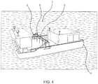
Fig. 4 shows the vessel with the device in a non-operative position, in a transport configuration, for example, -
Fig. 5 schematically shows initial tests in a plexiglass tube, -
Fig. 6 shows the droplet size distribution in the plexiglass tube experiment before, during and after a high pressure flushing treatment, -
Fig. 7 shows a droplet cloud formed during treatment of the oil by a high pressure jet in the plexiglass tube experiment, -
Fig. 8 schematically shows a meso-scale flume, with test data indicated in the square, -
Fig. 9a shows the experiment setup in the meso-scale flume, in a side view, with application at an angle of 90 degrees from a height of 50 cm, -
Fig. 9b shows a front view ofFig. 9a , -
Fig. 10a shows the experiment setup in the meso-scale flume, in a side view, with application at an angle of 45 degrees from a height of 25 cm, -
Fig. 10b shows a front view ofFig. 10a , -
Fig. 11 a shows the experiment setup in the meso-scale flume, in a side view, with application at an angle of 90 degrees from surface level (zero height),Fig. 11b shows a front view ofFig. 11a , and -
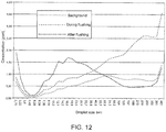
Fig. 12 shows the droplet size distribution before, during and after the treatment of oil by nozzles positioned at the water surface in the flume testing tank. - Referring to the drawings, an embodiment of the invention in the form of a device 1 and method for dispersing
oil 20 on water will be explained. The device 1 includes arig structure 2 for being mounted preferably in a front part of avessel 15.Rig structure 2 further includes a fronttransverse structure 5. Preferably, the fronttransverse structure 5 spans the entire width of the vessel.Fig. 3 shows an embodiment of the fronttransverse structure 5 having an extent that exceeds the width of the vessel so that it will cover an area wider than the width of the ship. In this connection, it is also noted that in other embodiments, thetransverse structure 5 may have an extent smaller than the width of the vessel. Thetransverse structure 5 is further provided with a number ofnozzles 7 for flushing withhigh pressure water 11 supplied from ahigh pressure facility 10 located on thevessel 15. In this connection, it should be noted that the number ofnozzles 7 may vary depending the configuration of the nozzle(s) and area of application, for example. - Preferably,
high pressure facility 10 will use water from the surrounding water body, which may be seawater or freshwater depending on the location at which the vessel operates.High pressure facility 10 further uses a pressure generator whereby water is provided at ultra-high pressure tonozzles 7. - In the present case,
rig structure 2 is shown moveably mounted to the vessel whereby the distance from the water surface ofnozzles 7 is adjustable. The direction ofnozzles 7 and the pressure of the high pressure water are also adjustable so that dispersed oil droplets within a preferred or optimum micron-size range of, preferably, 5-40 µm are obtained. - It is noted that
rig structure 5 could also be provided with pneumatic and ultrasound arrangements that further increases the oil dispersion efficiency. - Referring to
Fig. 1 ,rig structure 2 is further connected to anadditive storage tank 35. As shown in the figure, the additives are carried directly fromstorage tank 35 intohigh pressure water 11 fornozzles 7. It should be noted, however, that the additives could be carried directly fromstorage tank 35 to suitable additive nozzles provided on the fronttransverse structure 5. A combination of directly supplying the additives into high pressure water for the nozzles and supplying to separate additive nozzles provided on thetransverse structure 5 is also contemplated. In order to achieve a mechanical impact, particles must be carried directly from a storage tank into the water flow to the nozzles. In principle, other additives could be sprayed from separate nozzles without involving thehigh pressure water 11 fornozzles 7. The additives or materials can be particles, bacteria, nutrients, etc. - In the case of handling oil spill on water, the vessel will be prepared for operation in that
rig structure 2 andnozzles 7 as well as the pressure of the high pressure water are adjusted and regulated and optimized so as to obtain dispersed oil droplets of the desired micron-range size. -
Fig. 3 shows thevessel 15 with the device 1 during in for dispersingoil 20 on water (an oil slick). By means of device 1, the oil is dispersed into oil droplets within a micron-size range at the front of the vessel. The oil droplets will be further mixed into the water body by the forward movement of the vessel. The result thereof is that the oil slick is broken into micron-size droplets, after which natural currents and turbulence in the water body further help diluting the oil cloud so that it becomes less damaging or even harmless to the environment. -
Fig. 4 shows thevessel 15 with the device 1 in a non-operative configuration during transport to the operation site or to shore, for example. - It is noted that the principle of using high pressure water flushing for dispersing oil is novel and that it leads to a surprising effect in that an oil slick is broken into micron-sized droplets without any use of chemical dispersants.
- The dispersion of oil on water using a device according to the present invention is hence very efficient and may replace large parts of the current chemical dispersion means.
- Conventionally, the treatment of oil spill on water has been carried out by way of chemical dispersion. The formation of droplets smaller than 70 microns has been used as a criterion for successful dispersion treatment. In connection with the present application, extensive testing has been carried out in order to determine whether treatment of surface oil by way of high pressure spraying is efficiently able to produce droplets meeting the above criterion. The test was carried out in Sintefs meso-scale flume.
- The oil was treated using different techniques:
- Flushing onto the oil from a height above the water at an angle of 90 degrees.
- Flushing onto the oil from a height above the water at an angle of 45 degrees.
- Flushing directly into the water at the water surface.
- Conventionally, dispersant has been used in oil spill incidents (catastrophes) in order to improve the breakdown of the oil into small droplets. The smaller droplets will assist in removing the thick oil slick by diluting and dispersing it. Experience from field testing has indicated that the mechanical handling of oil may provide for sufficient shearing of the oil to disperse it from the sea surface.
- The use of chemical dispersion of oil on water is restricted by local regulations, the availability of chemicals, the efficacy of chemicals on the oil grade in question, as well as the application technology available. The present methodology provides for a chemical-free solution for dispersing oil on water by using an ultra-high pressure water jet solution applicable for small, medium, and large oil and chemical spills. The use of chemical dispersing agents is presently one of the main countermeasures against oil spill. Today, no non-chemical method exists that is applicable for dispersing oil on water.
- Some important facts regarding the use of chemical dispersing agents;
- The use of chemical dispersion of oil and water is controversial.
- The use of chemicals is limited by their availability.
- Large amounts of dispersant may be applied in an oil spill emergency operation.
- The cost of the chemical dispersant is another problem, with a cost per litre of more than NOK 30.
- During the accident in the Gulf of Mexico about 7000 metric tons of chemicals were applied to the oil slick.
- The efficacy of chemicals on the oil grade in question as well as the available application technology is a limiting factor.
- A limited research has been conducted in order to evaluate the feasibility of using high pressure nozzles as a means of dispersing oil from the sea surface. Initial testing was performed in a small plexiglass tank to document the ability of the nozzles to produce droplets of a desired size. A series of large scale tests was carried out in order to study the efficacy of different oil treatment techniques involving high pressure flushing.
- In all tests, the droplet size distribution was monitored using the
instrument LISST 100X (Sequoia Scientific). The instrument uses laser diffraction in the determination of the size distribution. The droplet sizes are classified as concentrations within 32 size bins from 2.5 to 500 microns. - The oil used is a lightly evaporated asphaltenic north sea oil.
- Flushing was effected by flushing nozzles (Washjet HSS 1/4MEG 2506 from Spraying Systems Company), which created a fan-shaped flushing jet with an angle of 29 degrees. Pressurized water was supplied by a
Kärcher HD 10/25 high pressure cleaner. The pressure was controlled by a needle valve and measured by a manometer located just before the nozzle(s). - Initial testing was carried out in a small plexiglass tank (diameter = 40 cm, height = 100 cm) in order to document the ability of the nozzles to produce droplets of the desirable size. An oil layer of 1 mm was contained within a plexiglass tube having a diameter of 10 cm. Flushing was conducted through a nozzle at about 15 bar on the inside of the tube. The small droplets formed escaped below the tube and into the testing tank. The measurement system for
LISST 100X was positioned right under the tube, in order to document the size distribution of the droplets formed. In this regard, reference is made toFig. 5 . - Even though the oil was confined within the plexiglass tube, the oil was pushed around on the surface by the flushing treatment. This rendered difficult the quantitative dispersion of the oil, and most of the oil still remained on the surface after the test. Enough droplets were formed to document that the energy of the system was sufficient to produce droplet sizes within the definition of dispersed oil (approximately 70 microns). The resulting droplet size distribution is shown in
Fig. 6 . - The result shows a binominal droplet distribution during the flushing treatment. The large droplets with a peak value above the detection limit of the instrument (> 500 microns) are most likely a combination of entrained air bubbles and oil droplets that have not been effectively processed in the high pressure flushing treatment. As the flushing is started, the larger droplets are precipitated and leave only a smaller of the two distributions in the water column. The droplets left in the water after the treatment exhibit a wide droplet size distribution with a peak value of approximately 75 microns. The distribution documented was visually evaluated to be dispersed oil, cf.
Fig. 7 . - Three larger tests were carried out in order to study the efficiency of different oil treatment techniques.
- 1) Application at an angle of 90 degrees from a height of 50 cm
- 2) Application at an angle of 45 degrees from a height of 25 cm
- 3) Application at an angle of 90 degrees at water surface level
- All tests were performed in Sintefs meso-scale flume. A schematic drawing of the flume is shown in
Fig. 8 . - The flume basin has a width of 0.5 meters and a depth of 1 meter and the overall length of the flume is about 10 meters. The total volume of the tank is 4.8 cubic meters of sea water. Two fans disposed in a covered wind tunnel control the wind velocity. A wave generator is used for generating waves of a controlled wave energy input. The tests were carried out in front of the wave generator and droplet size measurements were taken just inside the first tank of the test tank. The testing region is indicated by the square in the figure.
- Two flushing nozzles were mounted side by side at a
distance 50 cm above the water surface in the test tank. At this height the nozzles produced a continuous flushing line across the width of the tank. The three experiments are described separately below. - The nozzle pair was positioned 50 cm above water level and worked perpendicularly to the axis. Water was supplied at a pressure of up to 20 bars. In this regard, reference is made to
Figs. 9a and 9b . - An amount of air was entrained into the water as the jet hit the surface. A surface current was carried up by the jet itself, and as a result of resurfacing of the air bubbles. The current generated was stronger than the wind/wave induced currents in the test tank and the oil was not able to passively pass through the water jet. Attempts were made to capture the oil between the two barriers and to move the nozzles through the oil spill. This was a more successful approach, but a portion of the oil was still pushed away by the surface current induced. Due to the high energy in the water surrounding the jet, large droplets were also mixed into the water, but were immediately carried to the surface on exit from the turbulent area during the flushing. When a high concentration of small droplets is formed, a light brown cloud is assumed to form in the water. The formation of a droplet could not be observed visually in this experiment.
LISST 100X was not able to detect elevated droplet concentrations that could be discerned from the background noise in the test tank. - The nozzle pair was positioned 25 cm over water level and worked at an angle of 45 degrees to the surface. At half the angle and half the height, the flushing still produced a continuous flushing line spanning the width of the test tank. The angle was changed in order to address the problem of counteracting currents. The jet worked more in the direction of the wind/wave induced currents and the air bubbles surfaced further away from the jet. Also, at the 45 degrees angle, the flushing treatment (jets) was observed to "bounce off" the surface instead of penetrating it. This means that part of the energy was converted to a horizontal and upward movement. The flushing pressure was limited to 16 bar in order to reduce the amount of water flushed back into the air. In this regard, reference is made to
Fig. 10a and Fig. 10b . - Some turbulence still formed in front of the water jet. This turbulence prevented the oil from passing through when no wind or wave action was applied. As the wind and the wave generators were turned on, the oil moved slowly into the jet. Some of the oil was immediately converted to a brownish cloud when it passed through the jet. Most of the oil, however, passed through the jet as spots on surface oil or as large droplets.
LISST 100X was not able to detect elevated droplet concentrations that could be discerned from the background noise in the test tank. - In order to minimize the air entrainment and to maximize the energy transferred into the water, the system was positioned at the water surface so as to flush down into the water at an angle of 90 degrees. The reduced height also allowed the use of a higher pressure so the system was operated at 35 bars. In this regard, reference is made to
Fig. 11 a andFig. 11 b. - The nozzle system was arranged at the water surface and oil flow, therefore, was prevented by the application system itself. Consequently, oil was concentrated upstream of the nozzles. After the high pressure flushing was activated, parts of spots were pulled into the two jets. Only small amounts of oil were observed to pass through the system without being "treated" by the high pressure jet. The formation of light brown clouds could be observed immediately when the oil entered into the system. This observation could also be documented by
measurements using LISST 100X, cf.Fig. 12 . - During the treatment with high pressure flushing the droplet size distribution has a peak above the detection limit of
LISST 100X. This is assumed to be mainly due to the air bubbles entrained in the water. After the flushing was stopped, the large droplets were precipitated and a distribution having a maximum diameter of 20 microns was left in the water. -
LISST 100X does not discern between oil droplets and water bubbles. Therefore, a water sample was obtained subsequent to the flushing treatment in order to document that the concentrations measured were actually oil. The samples were extracted and analyzed for total oil in a spectrometer. The concentration was found to be 38ppm. The net concentration measured byLISST 100X was 29ppm (sum of the concentration within all the reported size bins). This indicates that most droplets registered by LISST are oil droplets. - A limited number of treatment methods for treating surface oil by way of high pressure flushing were tested in the channel test tank.
- Flushing directly into the water at a pressure of 35 bars resulted in the best documented effect. Only small amount s of oil were observed to be make it through the system without being treated by the jet. Droplets formed following the flushing treatment were measured to have a mean volume distribution of 20 microns. As mentioned earlier, a typically used criterion for the success of a dispersion operation (treatment with chemicals) is the formation of droplets having an average droplet diameter of less than 70 microns.
- Flushing from a distance above the water surface resulted in the entrainment of an amount of air bubbles in the water. The air bubbles that returned to the surface together with the energy from the flushing induced an outwelling current that helped pushing the oil away from the flushing line. This problem was partially addressed by applying the flushing treatment at an angle. Application at an angle made it easier to have the oil enter into the flushing line. The angle of 45 degrees, however, made the flushing treatment "bounce off' of the water surface and a portion of the downward acting force from the jet was lost. The meso-scale flume turned out to be under-dimensioned for this type of testing. Both tests involving application from a height had to be carried out at a limited pressure, in order to avoid damaging equipment in the testing tank.
- The experiments led to the following key conclusions;
- It is possible to efficiently disperse oil by using a high pressure water jet system.
- The final configuration of the system can be further developed.
- It is necessary to study the impact of different types of oil and weather conditions, but it is assumed that such factors will be of less importance here than with the alternative technique using chemical dispersants.
- The system may be incorporated into different oil spill control systems (small/large scale, small/large vessels).
- Based on the studies conducted we have found that the prerequisites for the proper operation of chemical-free high pressure water jet systems are the following;
- 1) It is necessary that the system delivers an ultrahigh pressure water jet, preferably above 30-40 bars per nozzle. This places strict requirements on the high pressure water supply system as well as to the design of the nozzles as well as the internal configuration of the individual nozzles.
- 2) It is necessary that the water fan from each nozzle is concentrated in order to reduce the amount of air pulled down together with the water jet.
- 3) It is necessary that the nozzle outlet is located near the water surface. 0-20 cm would be desirable, but the distance can be increased if the water pressure is increased and/or the concentration of water jets is increased (narrow fan). The closer to the surface the water fan is, the wider it can be, and it has been found that it is possible to tune the combination of surface distance and water fan (jet) width.
- 4) In order to be able to cover a large surface area the nozzle should be arranged in a stand that allows a certain width of water to be covered as the vessel carrying the system moves through the oil slick on the surface.
The public opinion (various interest groups) is often opposed to the use of chemicals, so that the method is disputed.
Claims (14)
- A vessel (15) for dispersing oil (20) on water, comprising:a rig structure (2) mounted on the vessel (15), preferably in a front part thereof, the rig structure (2) including a front transverse structure (5) provided with nozzles (7) for flushing with high pressure water (11) supplied from a high pressure facility (10) located on the vessel (15),characterized in that the direction and distance of the nozzles (7) to the water surface as well as the pressure of the high pressure water (11) are adjustable, the number of nozzles (7) being chosen so that a large number of high pressure, narrow jet nozzles are used for larger distances from the water surface, and a smaller number of wider-jet nozzles are used for smaller distances from the water surface, whereby dispersed oil droplets within a micron-size range are obtained, and the oil droplets are mixed into a body of water by the forward motion of the vessel (15).
- The vessel (15) of any of the preceding claims,
characterized in that the rig structure (5) is further provided with pneumatic and ultrasound arrangements. - The vessel (15) of any of the preceding claims,
characterized in that flushing is carried out at a preferred pressure of 35 bar per nozzle (7). - The vessel (15) of any of the preceding claims,
characterized in that the high pressure facility (10) uses water from a surrounding body of water. - The vessel (15) of any of the preceding claims,
characterized in that the body of water is seawater. - The vessel (15) of any of the preceding claims,
characterized in that the body of water is freshwater. - The vessel (15) of any of the preceding claims,
characterized in that the high pressure facility (10) uses a pressure generator whereby the water is provided at ultrahigh pressure to the at least one nozzle (7). - The vessel (15) of any of the preceding claims,
characterized in that the rig structure (2) is rigidly mounted with fixed positions relative to the vessel. - The vessel (15) of claim 1,
characterized in that the rig structure (2) is moveably mounted to the vessel (15). - The vessel (15) of any of the preceding claims,
characterized in that the rig structure (2) is further connected to an additive storage tank (35). - The vessel (15) of claim 10,
characterized in that the additives are provided directly from the storage tank (35) into the high pressure water (11) for the nozzle(s) (7). - The vessel (15) of claim 10,
characterized in that the additives are provided directly from the storage tank (35) to separate additive nozzles provided on the front transverse structure (5). - The vessel (15) of claims 10, 11, or 12,
characterized in that the additives are at least one of the following: particles, bacteria, nutrients, and chemicals. - A method of dispersing oil (20) on water, comprising:a rig structure (2) mounted preferably in a front part of a vessel (15), the rig structure (2) including a front transverse structure (5) provided with nozzles (7) for flushing with high pressure water (11) supplied from a high pressure facility (10) located on the vessel (15), characterized in that the direction and distance of the nozzles (7) to the water surface as well as the pressure of the high pressure water (11) is adjusted, the number of nozzles (7) being selected so that a large number of high pressure, narrow jet nozzles are used for larger distances from the water surface and a smaller number of wider-jet nozzles are used for small-ler distances from the water surface, whereby dispersed oil droplets within a micron-size range are obtained, and the oil droplets are mixed into a body of water by the forward motion of the vessel.
Priority Applications (1)
| Application Number | Priority Date | Filing Date | Title |
|---|---|---|---|
| PL13844664T PL2906755T3 (en) | 2012-10-10 | 2013-10-07 | Device and method for dispersing oil on water |
Applications Claiming Priority (2)
| Application Number | Priority Date | Filing Date | Title |
|---|---|---|---|
| NO20121147A NO337117B1 (en) | 2012-10-10 | 2012-10-10 | Apparatus and method for dispersing oil on water |
| PCT/NO2013/050168 WO2014058324A1 (en) | 2012-10-10 | 2013-10-07 | Device and method for dispersing oil on water |
Publications (3)
| Publication Number | Publication Date |
|---|---|
| EP2906755A1 EP2906755A1 (en) | 2015-08-19 |
| EP2906755A4 EP2906755A4 (en) | 2016-06-15 |
| EP2906755B1 true EP2906755B1 (en) | 2017-10-04 |
Family
ID=50477675
Family Applications (1)
| Application Number | Title | Priority Date | Filing Date |
|---|---|---|---|
| EP13844664.6A Active EP2906755B1 (en) | 2012-10-10 | 2013-10-07 | Device and method for dispersing oil on water |
Country Status (12)
| Country | Link |
|---|---|
| US (2) | US20150275451A1 (en) |
| EP (1) | EP2906755B1 (en) |
| AU (1) | AU2013330511B2 (en) |
| BR (1) | BR112015007711B1 (en) |
| CA (1) | CA2886347C (en) |
| DK (1) | DK2906755T3 (en) |
| ES (1) | ES2654662T3 (en) |
| MX (1) | MX356180B (en) |
| NO (1) | NO337117B1 (en) |
| PL (1) | PL2906755T3 (en) |
| PT (1) | PT2906755T (en) |
| WO (1) | WO2014058324A1 (en) |
Families Citing this family (8)
| Publication number | Priority date | Publication date | Assignee | Title |
|---|---|---|---|---|
| CN106149651B (en) * | 2016-08-30 | 2023-12-19 | 武汉大学深圳研究院 | Marine petroleum leakage emergency treatment system and method |
| US10563384B2 (en) * | 2017-05-12 | 2020-02-18 | Norman Faiola | Quick clean faucet |
| DE102017117552B4 (en) * | 2017-08-02 | 2023-06-29 | Karl-Heinz ELMER | Watercraft and compressed air distribution device |
| AU2019312376A1 (en) * | 2018-07-27 | 2021-02-18 | Advanced Drainage Systems, Inc. | End caps for stormwater chambers and methods of making same |
| US11051505B2 (en) * | 2018-10-12 | 2021-07-06 | Deere & Company | Multi-fluid spray system and method for agricultural product application |
| US10842143B2 (en) * | 2018-10-12 | 2020-11-24 | Deere & Company | Multi-fluid spray system and method for agricultural product application |
| WO2020117066A1 (en) * | 2018-12-03 | 2020-06-11 | Sintef Tto As | Device and method for dispersing oil on water |
| GB2579106B (en) * | 2019-04-03 | 2021-12-29 | Kohler Mira Ltd | Spray head |
Family Cites Families (17)
| Publication number | Priority date | Publication date | Assignee | Title |
|---|---|---|---|---|
| US1202051A (en) * | 1915-01-04 | 1916-10-24 | Gerald R Cushman | Spraying-nozzle. |
| US3532622A (en) * | 1969-10-24 | 1970-10-06 | Ara Chem Inc | Oil slick dispersion method |
| US3762169A (en) * | 1972-08-23 | 1973-10-02 | Us Navy | Floating water jet for oil slick control |
| US4033869A (en) * | 1974-06-05 | 1977-07-05 | Marine Construction & Design Co. | Oil spill confining and directing apparatus and method using water spray booms |
| US4222868A (en) * | 1976-12-07 | 1980-09-16 | Arthur Kuris | Ultrasonic oil spill removal |
| US4182679A (en) * | 1978-06-20 | 1980-01-08 | Ralph Watts | Oil skimmer |
| US4425240A (en) * | 1980-03-18 | 1984-01-10 | Johnson Michael G | Plunging water jets for oil spill containment and recovery |
| DE3162731D1 (en) * | 1980-03-20 | 1984-04-26 | Delavan Ltd | Method of and apparatus for combatting water-borne pollution |
| GB2160190B (en) * | 1984-06-04 | 1988-06-22 | Marine Safety Services Limited | Apparatus for spraying dispersant onto an oil spill |
| FR2694737B1 (en) * | 1992-08-11 | 1994-10-28 | Eaux Cie Gle | Cleaner ship. |
| US5490940A (en) * | 1994-04-08 | 1996-02-13 | Exxon Production Research Company | Method for forming mineral solids-oil floccules |
| JP3295389B2 (en) * | 1999-01-12 | 2002-06-24 | エヌエスエンジニアリング株式会社 | Method and apparatus for restoring function of pavement surface material having water passage function |
| AU2001261115A1 (en) * | 2000-05-02 | 2001-11-12 | American Marine, Inc. | Contaminant slick dispersal apparatus and methods |
| US6533195B2 (en) * | 2000-05-25 | 2003-03-18 | Glas-Craft, Inc. | Variable angle airless nozzle and dispensing method |
| CN2772629Y (en) * | 2005-01-31 | 2006-04-19 | 深圳市龙善环保科技实业有限公司 | High-efficient spray tube of oil spilling dispersing agent |
| WO2010126426A1 (en) * | 2009-04-30 | 2010-11-04 | Orc Ab | Method and device for applying a dispersant or other substances to a water surface |
| NO335095B1 (en) * | 2012-10-25 | 2014-09-15 | Sinvent As | Multi-use tools for combating oil spills, preferably at sea |
-
2012
- 2012-10-10 NO NO20121147A patent/NO337117B1/en unknown
-
2013
- 2013-10-07 PL PL13844664T patent/PL2906755T3/en unknown
- 2013-10-07 WO PCT/NO2013/050168 patent/WO2014058324A1/en active Application Filing
- 2013-10-07 MX MX2015004495A patent/MX356180B/en active IP Right Grant
- 2013-10-07 PT PT138446646T patent/PT2906755T/en unknown
- 2013-10-07 ES ES13844664.6T patent/ES2654662T3/en active Active
- 2013-10-07 AU AU2013330511A patent/AU2013330511B2/en active Active
- 2013-10-07 CA CA2886347A patent/CA2886347C/en active Active
- 2013-10-07 BR BR112015007711-0A patent/BR112015007711B1/en active IP Right Grant
- 2013-10-07 DK DK13844664.6T patent/DK2906755T3/en active
- 2013-10-07 EP EP13844664.6A patent/EP2906755B1/en active Active
- 2013-10-07 US US14/433,206 patent/US20150275451A1/en not_active Abandoned
-
2017
- 2017-05-24 US US15/603,920 patent/US20180002881A1/en not_active Abandoned
Non-Patent Citations (1)
| Title |
|---|
| None * |
Also Published As
| Publication number | Publication date |
|---|---|
| EP2906755A4 (en) | 2016-06-15 |
| PT2906755T (en) | 2018-01-08 |
| BR112015007711A2 (en) | 2017-07-04 |
| US20150275451A1 (en) | 2015-10-01 |
| PL2906755T3 (en) | 2018-03-30 |
| NO20121147A1 (en) | 2014-04-11 |
| EP2906755A1 (en) | 2015-08-19 |
| CA2886347C (en) | 2018-08-21 |
| CA2886347A1 (en) | 2014-04-17 |
| MX356180B (en) | 2018-05-17 |
| US20180002881A1 (en) | 2018-01-04 |
| WO2014058324A9 (en) | 2015-06-18 |
| AU2013330511A2 (en) | 2015-06-04 |
| BR112015007711A8 (en) | 2018-11-06 |
| BR112015007711B1 (en) | 2021-09-21 |
| AU2013330511B2 (en) | 2017-06-08 |
| NO337117B1 (en) | 2016-01-25 |
| MX2015004495A (en) | 2016-03-31 |
| WO2014058324A1 (en) | 2014-04-17 |
| ES2654662T3 (en) | 2018-02-14 |
| DK2906755T3 (en) | 2018-01-08 |
| AU2013330511A1 (en) | 2015-04-16 |
Similar Documents
| Publication | Publication Date | Title |
|---|---|---|
| EP2906755B1 (en) | Device and method for dispersing oil on water | |
| JP4632782B2 (en) | Water treatment system and method | |
| Li et al. | Effects of temperature and wave conditions on chemical dispersion efficacy of heavy fuel oil in an experimental flow-through wave tank | |
| US10683626B2 (en) | Device and method for dispersing oil on water | |
| Belore et al. | Large-scale cold water dispersant effectiveness experiments with Alaskan crude oils and Corexit 9500 and 9527 dispersants | |
| CN102770341B (en) | For the method and apparatus of water treatment | |
| US3561601A (en) | Oil slick dispersion apparatus | |
| KR20150024071A (en) | Exhaust gas desulfurization apparatus for marine diesel engines | |
| Li et al. | Oil droplet size distribution as a function of energy dissipation rate in an experimental wave tank | |
| WO2020117066A1 (en) | Device and method for dispersing oil on water | |
| US20120018386A1 (en) | Deepwater oil recovery process | |
| Kato | Utilization of Cavitation for Environmental Protection-Killing Planktons and Dispersing Spilled Oil | |
| CN101712373A (en) | Intelligent anti-pirate infrared-detection cleansing solution sprayer | |
| US20150336822A1 (en) | Nozzle mixing methods for ship ballast tanks | |
| JP2009061376A (en) | Oil spill recovery treatment apparatus | |
| US9598830B2 (en) | Method and system for oil release management | |
| Kato et al. | Dispersion of spilled oil by a cavitating jet at sea | |
| Sommerville et al. | Orimulsion® | |
| Motolenich-Salas et al. | Vessel dispersant application in oil spill response: Research review | |
| Tsocalis et al. | A survey of classical and new response methods for marine oil spill cleanup | |
| Merlin et al. | Optimization of dispersant application, especially by ship | |
| KR102064100B1 (en) | Apparatus and method for merging processing ballaster water and exhausting emission of vessel | |
| EP0658515A2 (en) | Process for removing the oil pollution from liquids, particularly from water | |
| Bridge et al. | Enhancement of oilmineral-aggregate formation to mitigate oil spills in offshore oil and gas activities | |
| McClimans et al. | A short review of the state-of-the-art of pneumatic oil barriers and bubble flotation at sea |
Legal Events
| Date | Code | Title | Description |
|---|---|---|---|
| PUAI | Public reference made under article 153(3) epc to a published international application that has entered the european phase |
Free format text: ORIGINAL CODE: 0009012 |
|
| 17P | Request for examination filed |
Effective date: 20150325 |
|
| AK | Designated contracting states |
Kind code of ref document: A1 Designated state(s): AL AT BE BG CH CY CZ DE DK EE ES FI FR GB GR HR HU IE IS IT LI LT LU LV MC MK MT NL NO PL PT RO RS SE SI SK SM TR |
|
| AX | Request for extension of the european patent |
Extension state: BA ME |
|
| DAX | Request for extension of the european patent (deleted) | ||
| RA4 | Supplementary search report drawn up and despatched (corrected) |
Effective date: 20160517 |
|
| RIC1 | Information provided on ipc code assigned before grant |
Ipc: B01F 3/08 20060101ALI20160510BHEP Ipc: E02B 15/04 20060101AFI20160510BHEP |
|
| GRAP | Despatch of communication of intention to grant a patent |
Free format text: ORIGINAL CODE: EPIDOSNIGR1 |
|
| INTG | Intention to grant announced |
Effective date: 20170511 |
|
| GRAS | Grant fee paid |
Free format text: ORIGINAL CODE: EPIDOSNIGR3 |
|
| GRAA | (expected) grant |
Free format text: ORIGINAL CODE: 0009210 |
|
| AK | Designated contracting states |
Kind code of ref document: B1 Designated state(s): AL AT BE BG CH CY CZ DE DK EE ES FI FR GB GR HR HU IE IS IT LI LT LU LV MC MK MT NL NO PL PT RO RS SE SI SK SM TR |
|
| REG | Reference to a national code |
Ref country code: GB Ref legal event code: FG4D |
|
| REG | Reference to a national code |
Ref country code: CH Ref legal event code: EP |
|
| REG | Reference to a national code |
Ref country code: AT Ref legal event code: REF Ref document number: 934169 Country of ref document: AT Kind code of ref document: T Effective date: 20171015 |
|
| REG | Reference to a national code |
Ref country code: IE Ref legal event code: FG4D |
|
| REG | Reference to a national code |
Ref country code: DE Ref legal event code: R096 Ref document number: 602013027640 Country of ref document: DE |
|
| REG | Reference to a national code |
Ref country code: FR Ref legal event code: PLFP Year of fee payment: 5 |
|
| REG | Reference to a national code |
Ref country code: DK Ref legal event code: T3 Effective date: 20180105 Ref country code: PT Ref legal event code: SC4A Ref document number: 2906755 Country of ref document: PT Date of ref document: 20180108 Kind code of ref document: T Free format text: AVAILABILITY OF NATIONAL TRANSLATION Effective date: 20171229 |
|
| REG | Reference to a national code |
Ref country code: NL Ref legal event code: FP |
|
| REG | Reference to a national code |
Ref country code: SE Ref legal event code: TRGR |
|
| REG | Reference to a national code |
Ref country code: ES Ref legal event code: FG2A Ref document number: 2654662 Country of ref document: ES Kind code of ref document: T3 Effective date: 20180214 |
|
| REG | Reference to a national code |
Ref country code: LT Ref legal event code: MG4D |
|
| REG | Reference to a national code |
Ref country code: AT Ref legal event code: MK05 Ref document number: 934169 Country of ref document: AT Kind code of ref document: T Effective date: 20171004 |
|
| PG25 | Lapsed in a contracting state [announced via postgrant information from national office to epo] |
Ref country code: LT Free format text: LAPSE BECAUSE OF FAILURE TO SUBMIT A TRANSLATION OF THE DESCRIPTION OR TO PAY THE FEE WITHIN THE PRESCRIBED TIME-LIMIT Effective date: 20171004 Ref country code: NO Free format text: LAPSE BECAUSE OF FAILURE TO SUBMIT A TRANSLATION OF THE DESCRIPTION OR TO PAY THE FEE WITHIN THE PRESCRIBED TIME-LIMIT Effective date: 20180104 |
|
| PG25 | Lapsed in a contracting state [announced via postgrant information from national office to epo] |
Ref country code: RS Free format text: LAPSE BECAUSE OF FAILURE TO SUBMIT A TRANSLATION OF THE DESCRIPTION OR TO PAY THE FEE WITHIN THE PRESCRIBED TIME-LIMIT Effective date: 20171004 Ref country code: LV Free format text: LAPSE BECAUSE OF FAILURE TO SUBMIT A TRANSLATION OF THE DESCRIPTION OR TO PAY THE FEE WITHIN THE PRESCRIBED TIME-LIMIT Effective date: 20171004 Ref country code: HR Free format text: LAPSE BECAUSE OF FAILURE TO SUBMIT A TRANSLATION OF THE DESCRIPTION OR TO PAY THE FEE WITHIN THE PRESCRIBED TIME-LIMIT Effective date: 20171004 Ref country code: AT Free format text: LAPSE BECAUSE OF FAILURE TO SUBMIT A TRANSLATION OF THE DESCRIPTION OR TO PAY THE FEE WITHIN THE PRESCRIBED TIME-LIMIT Effective date: 20171004 Ref country code: IS Free format text: LAPSE BECAUSE OF FAILURE TO SUBMIT A TRANSLATION OF THE DESCRIPTION OR TO PAY THE FEE WITHIN THE PRESCRIBED TIME-LIMIT Effective date: 20180204 |
|
| REG | Reference to a national code |
Ref country code: CH Ref legal event code: PL |
|
| REG | Reference to a national code |
Ref country code: GR Ref legal event code: EP Ref document number: 20170403620 Country of ref document: GR Effective date: 20180518 |
|
| REG | Reference to a national code |
Ref country code: DE Ref legal event code: R097 Ref document number: 602013027640 Country of ref document: DE |
|
| REG | Reference to a national code |
Ref country code: IE Ref legal event code: MM4A |
|
| PG25 | Lapsed in a contracting state [announced via postgrant information from national office to epo] |
Ref country code: LI Free format text: LAPSE BECAUSE OF NON-PAYMENT OF DUE FEES Effective date: 20171031 Ref country code: CH Free format text: LAPSE BECAUSE OF NON-PAYMENT OF DUE FEES Effective date: 20171031 Ref country code: EE Free format text: LAPSE BECAUSE OF FAILURE TO SUBMIT A TRANSLATION OF THE DESCRIPTION OR TO PAY THE FEE WITHIN THE PRESCRIBED TIME-LIMIT Effective date: 20171004 Ref country code: MC Free format text: LAPSE BECAUSE OF FAILURE TO SUBMIT A TRANSLATION OF THE DESCRIPTION OR TO PAY THE FEE WITHIN THE PRESCRIBED TIME-LIMIT Effective date: 20171004 Ref country code: LU Free format text: LAPSE BECAUSE OF NON-PAYMENT OF DUE FEES Effective date: 20171007 Ref country code: SK Free format text: LAPSE BECAUSE OF FAILURE TO SUBMIT A TRANSLATION OF THE DESCRIPTION OR TO PAY THE FEE WITHIN THE PRESCRIBED TIME-LIMIT Effective date: 20171004 Ref country code: CZ Free format text: LAPSE BECAUSE OF FAILURE TO SUBMIT A TRANSLATION OF THE DESCRIPTION OR TO PAY THE FEE WITHIN THE PRESCRIBED TIME-LIMIT Effective date: 20171004 |
|
| PLBE | No opposition filed within time limit |
Free format text: ORIGINAL CODE: 0009261 |
|
| STAA | Information on the status of an ep patent application or granted ep patent |
Free format text: STATUS: NO OPPOSITION FILED WITHIN TIME LIMIT |
|
| REG | Reference to a national code |
Ref country code: BE Ref legal event code: MM Effective date: 20171031 |
|
| PG25 | Lapsed in a contracting state [announced via postgrant information from national office to epo] |
Ref country code: IT Free format text: LAPSE BECAUSE OF FAILURE TO SUBMIT A TRANSLATION OF THE DESCRIPTION OR TO PAY THE FEE WITHIN THE PRESCRIBED TIME-LIMIT Effective date: 20171004 Ref country code: RO Free format text: LAPSE BECAUSE OF FAILURE TO SUBMIT A TRANSLATION OF THE DESCRIPTION OR TO PAY THE FEE WITHIN THE PRESCRIBED TIME-LIMIT Effective date: 20171004 Ref country code: SM Free format text: LAPSE BECAUSE OF FAILURE TO SUBMIT A TRANSLATION OF THE DESCRIPTION OR TO PAY THE FEE WITHIN THE PRESCRIBED TIME-LIMIT Effective date: 20171004 Ref country code: BE Free format text: LAPSE BECAUSE OF NON-PAYMENT OF DUE FEES Effective date: 20171031 |
|
| 26N | No opposition filed |
Effective date: 20180705 |
|
| PG25 | Lapsed in a contracting state [announced via postgrant information from national office to epo] |
Ref country code: MT Free format text: LAPSE BECAUSE OF NON-PAYMENT OF DUE FEES Effective date: 20171007 |
|
| REG | Reference to a national code |
Ref country code: FR Ref legal event code: PLFP Year of fee payment: 6 |
|
| PG25 | Lapsed in a contracting state [announced via postgrant information from national office to epo] |
Ref country code: IE Free format text: LAPSE BECAUSE OF NON-PAYMENT OF DUE FEES Effective date: 20171007 |
|
| PG25 | Lapsed in a contracting state [announced via postgrant information from national office to epo] |
Ref country code: SI Free format text: LAPSE BECAUSE OF FAILURE TO SUBMIT A TRANSLATION OF THE DESCRIPTION OR TO PAY THE FEE WITHIN THE PRESCRIBED TIME-LIMIT Effective date: 20171004 |
|
| PG25 | Lapsed in a contracting state [announced via postgrant information from national office to epo] |
Ref country code: HU Free format text: LAPSE BECAUSE OF FAILURE TO SUBMIT A TRANSLATION OF THE DESCRIPTION OR TO PAY THE FEE WITHIN THE PRESCRIBED TIME-LIMIT; INVALID AB INITIO Effective date: 20131007 |
|
| PG25 | Lapsed in a contracting state [announced via postgrant information from national office to epo] |
Ref country code: CY Free format text: LAPSE BECAUSE OF FAILURE TO SUBMIT A TRANSLATION OF THE DESCRIPTION OR TO PAY THE FEE WITHIN THE PRESCRIBED TIME-LIMIT Effective date: 20171004 |
|
| PG25 | Lapsed in a contracting state [announced via postgrant information from national office to epo] |
Ref country code: MK Free format text: LAPSE BECAUSE OF FAILURE TO SUBMIT A TRANSLATION OF THE DESCRIPTION OR TO PAY THE FEE WITHIN THE PRESCRIBED TIME-LIMIT Effective date: 20171004 |
|
| PG25 | Lapsed in a contracting state [announced via postgrant information from national office to epo] |
Ref country code: AL Free format text: LAPSE BECAUSE OF FAILURE TO SUBMIT A TRANSLATION OF THE DESCRIPTION OR TO PAY THE FEE WITHIN THE PRESCRIBED TIME-LIMIT Effective date: 20171004 |
|
| PGFP | Annual fee paid to national office [announced via postgrant information from national office to epo] |
Ref country code: PL Payment date: 20210916 Year of fee payment: 9 Ref country code: TR Payment date: 20210916 Year of fee payment: 9 |
|
| PGFP | Annual fee paid to national office [announced via postgrant information from national office to epo] |
Ref country code: PT Payment date: 20210923 Year of fee payment: 9 |
|
| P01 | Opt-out of the competence of the unified patent court (upc) registered |
Effective date: 20230525 |
|
| PG25 | Lapsed in a contracting state [announced via postgrant information from national office to epo] |
Ref country code: PT Free format text: LAPSE BECAUSE OF NON-PAYMENT OF DUE FEES Effective date: 20230410 |
|
| PG25 | Lapsed in a contracting state [announced via postgrant information from national office to epo] |
Ref country code: PL Free format text: LAPSE BECAUSE OF NON-PAYMENT OF DUE FEES Effective date: 20221007 |
|
| PGFP | Annual fee paid to national office [announced via postgrant information from national office to epo] |
Ref country code: NL Payment date: 20231019 Year of fee payment: 11 |
|
| PGFP | Annual fee paid to national office [announced via postgrant information from national office to epo] |
Ref country code: GB Payment date: 20231020 Year of fee payment: 11 Ref country code: GR Payment date: 20231020 Year of fee payment: 11 |
|
| PGFP | Annual fee paid to national office [announced via postgrant information from national office to epo] |
Ref country code: ES Payment date: 20231227 Year of fee payment: 11 |
|
| PGFP | Annual fee paid to national office [announced via postgrant information from national office to epo] |
Ref country code: SE Payment date: 20231019 Year of fee payment: 11 Ref country code: FR Payment date: 20231025 Year of fee payment: 11 Ref country code: FI Payment date: 20231020 Year of fee payment: 11 Ref country code: DK Payment date: 20231024 Year of fee payment: 11 Ref country code: DE Payment date: 20231020 Year of fee payment: 11 Ref country code: BG Payment date: 20231020 Year of fee payment: 11 |