EP2905452A2 - Asil B-compliant implementation of automotive safety-related functions by means of a high diagnosability, quality managed-compliant integrated circuit - Google Patents
Asil B-compliant implementation of automotive safety-related functions by means of a high diagnosability, quality managed-compliant integrated circuit Download PDFInfo
- Publication number
- EP2905452A2 EP2905452A2 EP14179201.0A EP14179201A EP2905452A2 EP 2905452 A2 EP2905452 A2 EP 2905452A2 EP 14179201 A EP14179201 A EP 14179201A EP 2905452 A2 EP2905452 A2 EP 2905452A2
- Authority
- EP
- European Patent Office
- Prior art keywords
- safety
- designed
- microcontroller
- automotive
- integrated circuit
- Prior art date
- Legal status (The legal status is an assumption and is not a legal conclusion. Google has not performed a legal analysis and makes no representation as to the accuracy of the status listed.)
- Granted
Links
- 238000002485 combustion reaction Methods 0.000 claims abstract description 19
- 238000003745 diagnosis Methods 0.000 claims abstract description 16
- 238000012544 monitoring process Methods 0.000 claims abstract description 9
- 238000012360 testing method Methods 0.000 claims description 27
- 230000001902 propagating effect Effects 0.000 claims description 5
- 238000006243 chemical reaction Methods 0.000 claims description 4
- 238000002955 isolation Methods 0.000 claims description 4
- 238000004891 communication Methods 0.000 claims description 2
- 230000001960 triggered effect Effects 0.000 claims 1
- 238000010586 diagram Methods 0.000 description 9
- 230000010354 integration Effects 0.000 description 2
- 238000000034 method Methods 0.000 description 2
- 230000000644 propagated effect Effects 0.000 description 2
- 238000011161 development Methods 0.000 description 1
- 230000000694 effects Effects 0.000 description 1
- 238000005516 engineering process Methods 0.000 description 1
- 238000004519 manufacturing process Methods 0.000 description 1
- 238000012986 modification Methods 0.000 description 1
- 230000004048 modification Effects 0.000 description 1
- 238000012502 risk assessment Methods 0.000 description 1
Images


Classifications
-
- F—MECHANICAL ENGINEERING; LIGHTING; HEATING; WEAPONS; BLASTING
- F02—COMBUSTION ENGINES; HOT-GAS OR COMBUSTION-PRODUCT ENGINE PLANTS
- F02D—CONTROLLING COMBUSTION ENGINES
- F02D29/00—Controlling engines, such controlling being peculiar to the devices driven thereby, the devices being other than parts or accessories essential to engine operation, e.g. controlling of engines by signals external thereto
- F02D29/02—Controlling engines, such controlling being peculiar to the devices driven thereby, the devices being other than parts or accessories essential to engine operation, e.g. controlling of engines by signals external thereto peculiar to engines driving vehicles; peculiar to engines driving variable pitch propellers
-
- B—PERFORMING OPERATIONS; TRANSPORTING
- B60—VEHICLES IN GENERAL
- B60W—CONJOINT CONTROL OF VEHICLE SUB-UNITS OF DIFFERENT TYPE OR DIFFERENT FUNCTION; CONTROL SYSTEMS SPECIALLY ADAPTED FOR HYBRID VEHICLES; ROAD VEHICLE DRIVE CONTROL SYSTEMS FOR PURPOSES NOT RELATED TO THE CONTROL OF A PARTICULAR SUB-UNIT
- B60W10/00—Conjoint control of vehicle sub-units of different type or different function
- B60W10/04—Conjoint control of vehicle sub-units of different type or different function including control of propulsion units
- B60W10/06—Conjoint control of vehicle sub-units of different type or different function including control of propulsion units including control of combustion engines
-
- B—PERFORMING OPERATIONS; TRANSPORTING
- B60—VEHICLES IN GENERAL
- B60W—CONJOINT CONTROL OF VEHICLE SUB-UNITS OF DIFFERENT TYPE OR DIFFERENT FUNCTION; CONTROL SYSTEMS SPECIALLY ADAPTED FOR HYBRID VEHICLES; ROAD VEHICLE DRIVE CONTROL SYSTEMS FOR PURPOSES NOT RELATED TO THE CONTROL OF A PARTICULAR SUB-UNIT
- B60W50/00—Details of control systems for road vehicle drive control not related to the control of a particular sub-unit, e.g. process diagnostic or vehicle driver interfaces
- B60W50/02—Ensuring safety in case of control system failures, e.g. by diagnosing, circumventing or fixing failures
-
- F—MECHANICAL ENGINEERING; LIGHTING; HEATING; WEAPONS; BLASTING
- F02—COMBUSTION ENGINES; HOT-GAS OR COMBUSTION-PRODUCT ENGINE PLANTS
- F02D—CONTROLLING COMBUSTION ENGINES
- F02D41/00—Electrical control of supply of combustible mixture or its constituents
- F02D41/22—Safety or indicating devices for abnormal conditions
-
- F—MECHANICAL ENGINEERING; LIGHTING; HEATING; WEAPONS; BLASTING
- F02—COMBUSTION ENGINES; HOT-GAS OR COMBUSTION-PRODUCT ENGINE PLANTS
- F02D—CONTROLLING COMBUSTION ENGINES
- F02D41/00—Electrical control of supply of combustible mixture or its constituents
- F02D41/24—Electrical control of supply of combustible mixture or its constituents characterised by the use of digital means
- F02D41/26—Electrical control of supply of combustible mixture or its constituents characterised by the use of digital means using computer, e.g. microprocessor
-
- G—PHYSICS
- G07—CHECKING-DEVICES
- G07C—TIME OR ATTENDANCE REGISTERS; REGISTERING OR INDICATING THE WORKING OF MACHINES; GENERATING RANDOM NUMBERS; VOTING OR LOTTERY APPARATUS; ARRANGEMENTS, SYSTEMS OR APPARATUS FOR CHECKING NOT PROVIDED FOR ELSEWHERE
- G07C5/00—Registering or indicating the working of vehicles
- G07C5/08—Registering or indicating performance data other than driving, working, idle, or waiting time, with or without registering driving, working, idle or waiting time
- G07C5/0808—Diagnosing performance data
-
- B—PERFORMING OPERATIONS; TRANSPORTING
- B60—VEHICLES IN GENERAL
- B60W—CONJOINT CONTROL OF VEHICLE SUB-UNITS OF DIFFERENT TYPE OR DIFFERENT FUNCTION; CONTROL SYSTEMS SPECIALLY ADAPTED FOR HYBRID VEHICLES; ROAD VEHICLE DRIVE CONTROL SYSTEMS FOR PURPOSES NOT RELATED TO THE CONTROL OF A PARTICULAR SUB-UNIT
- B60W50/00—Details of control systems for road vehicle drive control not related to the control of a particular sub-unit, e.g. process diagnostic or vehicle driver interfaces
- B60W50/02—Ensuring safety in case of control system failures, e.g. by diagnosing, circumventing or fixing failures
- B60W50/0205—Diagnosing or detecting failures; Failure detection models
- B60W2050/021—Means for detecting failure or malfunction
-
- B—PERFORMING OPERATIONS; TRANSPORTING
- B60—VEHICLES IN GENERAL
- B60W—CONJOINT CONTROL OF VEHICLE SUB-UNITS OF DIFFERENT TYPE OR DIFFERENT FUNCTION; CONTROL SYSTEMS SPECIALLY ADAPTED FOR HYBRID VEHICLES; ROAD VEHICLE DRIVE CONTROL SYSTEMS FOR PURPOSES NOT RELATED TO THE CONTROL OF A PARTICULAR SUB-UNIT
- B60W50/00—Details of control systems for road vehicle drive control not related to the control of a particular sub-unit, e.g. process diagnostic or vehicle driver interfaces
- B60W50/02—Ensuring safety in case of control system failures, e.g. by diagnosing, circumventing or fixing failures
- B60W50/029—Adapting to failures or work around with other constraints, e.g. circumvention by avoiding use of failed parts
- B60W2050/0292—Fail-safe or redundant systems, e.g. limp-home or backup systems
-
- B—PERFORMING OPERATIONS; TRANSPORTING
- B60—VEHICLES IN GENERAL
- B60W—CONJOINT CONTROL OF VEHICLE SUB-UNITS OF DIFFERENT TYPE OR DIFFERENT FUNCTION; CONTROL SYSTEMS SPECIALLY ADAPTED FOR HYBRID VEHICLES; ROAD VEHICLE DRIVE CONTROL SYSTEMS FOR PURPOSES NOT RELATED TO THE CONTROL OF A PARTICULAR SUB-UNIT
- B60W50/00—Details of control systems for road vehicle drive control not related to the control of a particular sub-unit, e.g. process diagnostic or vehicle driver interfaces
- B60W50/04—Monitoring the functioning of the control system
- B60W2050/041—Built in Test Equipment [BITE]
-
- G—PHYSICS
- G05—CONTROLLING; REGULATING
- G05B—CONTROL OR REGULATING SYSTEMS IN GENERAL; FUNCTIONAL ELEMENTS OF SUCH SYSTEMS; MONITORING OR TESTING ARRANGEMENTS FOR SUCH SYSTEMS OR ELEMENTS
- G05B2219/00—Program-control systems
- G05B2219/20—Pc systems
- G05B2219/24—Pc safety
- G05B2219/24021—Separate processor for monitoring system
-
- G—PHYSICS
- G05—CONTROLLING; REGULATING
- G05B—CONTROL OR REGULATING SYSTEMS IN GENERAL; FUNCTIONAL ELEMENTS OF SUCH SYSTEMS; MONITORING OR TESTING ARRANGEMENTS FOR SUCH SYSTEMS OR ELEMENTS
- G05B2219/00—Program-control systems
- G05B2219/20—Pc systems
- G05B2219/24—Pc safety
- G05B2219/24044—Second controller monitors diagnostics system of first controller
-
- G—PHYSICS
- G05—CONTROLLING; REGULATING
- G05B—CONTROL OR REGULATING SYSTEMS IN GENERAL; FUNCTIONAL ELEMENTS OF SUCH SYSTEMS; MONITORING OR TESTING ARRANGEMENTS FOR SUCH SYSTEMS OR ELEMENTS
- G05B2219/00—Program-control systems
- G05B2219/20—Pc systems
- G05B2219/24—Pc safety
- G05B2219/24199—Recover from fault, malfunction, go to safe state, correct and set new sequence
-
- G—PHYSICS
- G05—CONTROLLING; REGULATING
- G05B—CONTROL OR REGULATING SYSTEMS IN GENERAL; FUNCTIONAL ELEMENTS OF SUCH SYSTEMS; MONITORING OR TESTING ARRANGEMENTS FOR SUCH SYSTEMS OR ELEMENTS
- G05B2219/00—Program-control systems
- G05B2219/20—Pc systems
- G05B2219/26—Pc applications
- G05B2219/2637—Vehicle, car, auto, wheelchair
-
- G—PHYSICS
- G05—CONTROLLING; REGULATING
- G05B—CONTROL OR REGULATING SYSTEMS IN GENERAL; FUNCTIONAL ELEMENTS OF SUCH SYSTEMS; MONITORING OR TESTING ARRANGEMENTS FOR SUCH SYSTEMS OR ELEMENTS
- G05B2219/00—Program-control systems
- G05B2219/30—Nc systems
- G05B2219/33—Director till display
- G05B2219/33104—Tasks, functions are distributed over different cpu
-
- G—PHYSICS
- G05—CONTROLLING; REGULATING
- G05B—CONTROL OR REGULATING SYSTEMS IN GENERAL; FUNCTIONAL ELEMENTS OF SUCH SYSTEMS; MONITORING OR TESTING ARRANGEMENTS FOR SUCH SYSTEMS OR ELEMENTS
- G05B2219/00—Program-control systems
- G05B2219/30—Nc systems
- G05B2219/33—Director till display
- G05B2219/33273—DCS distributed, decentralised controlsystem, multiprocessor
Definitions
- the present invention relates to Automotive Safety Integrity Level B (ASIL B)-compliant implementation of automotive safety-related functions by means of a high diagnosability, Quality Managed (QM)-compliant integrated circuit.
- ASIL B Automotive Safety Integrity Level B
- QM Quality Managed
- Standard ISO 26262 provides the process and product requirements for lessening the effects of system and hardware failures. This standard deals with functional safety concepts applied to the automotive field, while pursuing the absence of unacceptable risks due to hazards caused by undesired behaviour of the systems.
- Standard ISO 26262 defines four Automotive Safety Integrity Levels (ASIL) while specifying risks and the needs for reducing risk.
- ASIL can take on four different values for safety-related functions, indicated with letters, from the lowest, indicated by the letter D, which is the most critical level in terms of safety integrity, up to the highest level, indicated by the letter A, which is the minimum safety integrity level.
- ASIL may also take on the value QM (Quality Managed), which however is assigned to non-safety-related functions.
- the object of the present invention is therefore to provide a solution which allows the above need to be met.
- an automotive internal combustion engine electronic control unit is provided, as defined in the appended claims.
- Figure 1 shows a principle block diagram which shows the way in which an automotive safety-related function, indicated by F, may be implemented in such a manner so as to be ASIL B compliant by means of an integrated circuit developed according to Quality Managed standards.
- U-Chip Umbrella-Chip
- ⁇ C microcontroller
- U-Chip in order to ensure that an F is implemented by the ECU with ASIL B, in addition to function F, U-Chip also performs a diagnosis function, indicated by DIAG, designed to detect failures that may jeopardize the proper performance of F. As it is performed by U-Chip, DIAG is obviously performed with the same QM ASIL with which F is performed.
- a monitoring function indicated by MON and designed to monitor the operability of DIAG and in particular to detect failures that may compromise the effectiveness of the diagnostic capability of DIAG, is instead performed by ⁇ C of ECU, which is instead designed to perform functions with an ASIL B and is exempt from any functional interferences resulting from failures in the performance of DIAG or F.
- FIG. 2 shows a block diagram of the functions F performed by U-Chip, which comprise:
- FIG. 3 instead shows a block diagram of how F and DIAG are implemented in U-Chip, in which:
- DIAG is managed by the following signals:
- MON is designed to re-perform a group of well-defined tests performed by DIAG in order to verify, on the one hand, the proper performance of F and on the other, the proper performance of DIAG.
- MON detects a test failure of F or a mismatch between a result of a test reported by DIAG and a result of a test reported by MON, then MON triggers a safe reaction, which could conveniently consist of de-energizing safety-related loads, as will be more apparent by the description in figure 4 .
- MON designed to monitor U-Chip, and in particular the operability of DIAG, but also other safe-related integrated circuits, as will be more apparent by the description in figure 4 .
- one of the elements that ensures the proper performance of the functional architecture of the invention is that ⁇ C of ECU be exempt from functional interferences resulting from failures in the performance of DIAG or F.
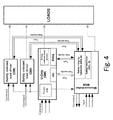
- Figure 4 shows a block diagram of a safety architecture of ECU which allows this propagation to be mitigated while protecting part of the safety-related loads.
- U-Chip is provided with its own embedded safety-related load drivers, through which it drives given safety-related loads, hereinafter indicated by G2, while ⁇ C is not provided with its own embedded safety-related load drivers, but controls external safety-related load drivers of ECU, through which it drives other safety-related loads, hereinafter indicated by G1.
- the external load drivers controlled by ⁇ C are provided with respective embedded Over/Under Voltage Monitors (O/U VM) designed to detect presence of an overvoltage propagating from ⁇ C towards the loads G1 and to responsively generate a de-energization command for the loads G1, thus causing the de-energizing thereof and protecting them from any damage due to overvoltage.
- O/U VM Over/Under Voltage Monitors
- the load drivers controlled by ⁇ C are powered by the power supplies of U-Chip, which are therefore shared by U-Chip, ⁇ C and the external load drivers controlled by ⁇ C.
Abstract
Description
- The present invention relates to Automotive Safety Integrity Level B (ASIL B)-compliant implementation of automotive safety-related functions by means of a high diagnosability, Quality Managed (QM)-compliant integrated circuit.
- As is known, safety is one of the main subjects in the automotive industry. The on-vehicle integration of electric and electronic systems requires development processes and safety content, and also the opportunity to provide proof that all reasonable safety goals have been met.
- New technologies based on functionalities distributed in various electronic control units typically developed by different suppliers increase the complexity, software content and mechatronic implementation and accordingly, the risks of system and hardware failures.
- Increasing the integration of electric and electronic apparatuses (including programmable devices, as well as electromechanical components) in automotive systems has led to the introduction of international standard ISO 26262, which is dealt with by functional safety standard IEC 61508 for electric/electronic systems in industry.
- Standard ISO 26262 provides the process and product requirements for lessening the effects of system and hardware failures. This standard deals with functional safety concepts applied to the automotive field, while pursuing the absence of unacceptable risks due to hazards caused by undesired behaviour of the systems.
- Standard ISO 26262 defines four Automotive Safety Integrity Levels (ASIL) while specifying risks and the needs for reducing risk. ASIL can take on four different values for safety-related functions, indicated with letters, from the lowest, indicated by the letter D, which is the most critical level in terms of safety integrity, up to the highest level, indicated by the letter A, which is the minimum safety integrity level. ASIL may also take on the value QM (Quality Managed), which however is assigned to non-safety-related functions.
- The hazard and risk assessment set forth by standard ISO 26262, and the reference document "Standardized E-Gas-Monitoring Concept for Engine Controls of Otto and Diesel Engines", version 5.0, published by the German Association of the Automotive Industry or VDA (Verband der Automobilindustrie), provide that the implementation of automotive safety-related functions involved in managing the supply of torque by an internal combustion engine have ASIL B.
- Designing, developing and manufacturing integrated circuits that implement ASIL B-compliant automotive safety-related functions require significant resources. It would therefore be appreciated to define a more affordable solution that allows the requirements set forth in the above-mentioned standard and in the above-mentioned document to be met by means of integrated circuits which, although they are designed, developed and manufactured with Quality Managed criteria, allow ASIL B safety-related functions to be implemented in accordance with to the provisions set forth in the above-mentioned standard and in the above-mentioned document.
- The object of the present invention is therefore to provide a solution which allows the above need to be met.
- According to the present invention, an automotive internal combustion engine electronic control unit is provided, as defined in the appended claims.
-
-
Figure 1 shows a principle block diagram which shows the way in which an automotive safety-related function, indicated by F, may be implemented in such a manner so as to be ASIL B compliant by means of the implementation thereof according to Quality Managed standards, in which a diagnosis function DIAG may be developed according to Quality Managed standards and in which a monitoring function MON may be developed according to standard ASIL B; the implementation of function F and of function DIAG is allocated to an integrated circuit U-Chip; the implementation of function MON is instead allocated to a microcontroller µC. -
Figure 2 shows a block diagram of the functions performed by an integrated circuit. -
Figure 3 shows a block diagram of a generic diagnostic function DIAG implemented in an integrated circuit U-Chip, according to that diagrammatically shown infigure 1 . -
Figure 4 shows a block diagram of a safety architecture of an automotive internal combustion engine electronic control unit. -
Figure 5 shows a block diagram of how an overvoltage may propagate within the automotive internal combustion engine electronic control unit infigure 4 . - The present invention will now be described in detail with reference to the accompanying figures to allow a skilled person to make and use it. Various modifications to the embodiments described will be immediately apparent to skilled persons and the generic principles described may be applied to other embodiments and applications without departing from the scope of protection of the present invention, as defined in the appended claims. Therefore, the present invention is not be considered limited to the embodiments described and illustrated, rather is to be given the broadest scope of protection conforming with the principles and characteristics herein described and claimed.
-
Figure 1 shows a principle block diagram which shows the way in which an automotive safety-related function, indicated by F, may be implemented in such a manner so as to be ASIL B compliant by means of an integrated circuit developed according to Quality Managed standards. - The integrated circuit, hereinafter indicated in short with U-Chip (Umbrella-Chip), dedicated, among other things, to performing F, is arranged in an automotive internal combustion engine electronic control unit, indicated by ECU, is an electronic component distinct from and communicating with the microcontroller, indicated by µC, of ECU, and is designed to perform Quality Managed-compliant functions, which, therefore, fail to reach the ASIL B required for the implementation of F.
- Whatever indicated below concerning F and shown in
figure 1 is valid and repeatable for each F performed by U-Chip wanted to be performed by the ECU in compliance with ASIL B requirements. - With reference to
figure 1 , in order to ensure that an F is implemented by the ECU with ASIL B, in addition to function F, U-Chip also performs a diagnosis function, indicated by DIAG, designed to detect failures that may jeopardize the proper performance of F. As it is performed by U-Chip, DIAG is obviously performed with the same QM ASIL with which F is performed. - A monitoring function, indicated by MON and designed to monitor the operability of DIAG and in particular to detect failures that may compromise the effectiveness of the diagnostic capability of DIAG, is instead performed by µC of ECU, which is instead designed to perform functions with an ASIL B and is exempt from any functional interferences resulting from failures in the performance of DIAG or F.
-
Figure 2 shows a block diagram of the functions F performed by U-Chip, which comprise: - intelligent functions comprising:
- smart crank management
- intelligent watchdog
- flying wheel interface
- wake-up and power enable logic
- power supplies comprising:
- ECU power supplies
- sensor power supplies
- communication interfaces comprising:
- MSC (Micro Second Channel) interface
- LIN (Local Interconnect Network) transceiver
- CAN (Controller Area Network) transceiver
- load driving channels.
-
Figure 3 instead shows a block diagram of how F and DIAG are implemented in U-Chip, in which: - TC is a Test Controller designed to enable and synchronize the performance of DIAG,
- CUT is a Circuit Under Test designed to implement function F that DIAG is to monitor,
- TPG is a Test Pattern Generator designed to test correct operation of CUT,
- ORA is an Output Response Analyzer designed to compare the test results, and in particular to compare the output of CUT with an expected output and provide an indication of test success or test failure,
- IIC is an Input Isolation Circuit designed to connect the input of CUT to TPG when DIAG must be performed,
- OIC is an Output Isolation Circuit designed to connect the output of CUT to ORA when DIAG must be performed.
- Generally, DIAG is managed by the following signals:
- MSC_BIST_ENABLE: signal from µC for test enabling
- MSC_BIST_TRIGGER: signal from µC that triggers the performance of DIAG
- MSC_BIST_END: signal from TC that indicates the end of the performance of DIAG to µC
- MSC_PASS_FAIL: result of the performance of DIAG
- MON is designed to re-perform a group of well-defined tests performed by DIAG in order to verify, on the one hand, the proper performance of F and on the other, the proper performance of DIAG.
- If MON detects a test failure of F or a mismatch between a result of a test reported by DIAG and a result of a test reported by MON, then MON triggers a safe reaction, which could conveniently consist of de-energizing safety-related loads, as will be more apparent by the description in
figure 4 . - Finally, not only is MON designed to monitor U-Chip, and in particular the operability of DIAG, but also other safe-related integrated circuits, as will be more apparent by the description in
figure 4 . - As indicated above, one of the elements that ensures the proper performance of the functional architecture of the invention is that µC of ECU be exempt from functional interferences resulting from failures in the performance of DIAG or F.
- A well-known cause which may compromise this absence of functional interference is the presence of an overvoltage propagating from U-Chip to µC which is designated to the performance of MON.
-
Figure 4 shows a block diagram of a safety architecture of ECU which allows this propagation to be mitigated while protecting part of the safety-related loads. - It is worth noting that U-Chip is provided with its own embedded safety-related load drivers, through which it drives given safety-related loads, hereinafter indicated by G2, while µC is not provided with its own embedded safety-related load drivers, but controls external safety-related load drivers of ECU, through which it drives other safety-related loads, hereinafter indicated by G1.
- The external load drivers controlled by µC are provided with respective embedded Over/Under Voltage Monitors (O/U VM) designed to detect presence of an overvoltage propagating from µC towards the loads G1 and to responsively generate a de-energization command for the loads G1, thus causing the de-energizing thereof and protecting them from any damage due to overvoltage.
- Furthermore, as is worth noting, the load drivers controlled by µC, like µC itself, are powered by the power supplies of U-Chip, which are therefore shared by U-Chip, µC and the external load drivers controlled by µC.
- For this reason, a possible overvoltage generated within U-Chip and propagating into µC may compromise the functionality of MON, obviously in addition to the loads G2 driven by U-Chip.
- As instead shown in
figure 5 , due to the implementation of external load drivers provided with embedded over/under voltage monitors, a possible overvoltage generated in U-Chip and propagated to µC and, therefrom to the loads G1, or generated directly in µC and propagated to the loads G1, is detected by the embedded over/under voltage monitors, which responsively trigger a safe reaction comprising the generation of a de-energization command for the loads G1, thus causing the de-energization thereof and protecting them from possible damage due to overvoltage.
Claims (11)
- An automotive internal combustion engine electronic control unit (ECU) required to perform safety-related functions (F) with a predetermined automotive safety integrity level (ASIL); wherein the automotive electronic control unit (ECU) comprises a microcontroller (µC) and an integrated circuit (U-Chip) distinct from and communicating with the microcontroller (µC); wherein the microcontroller (µC) is designed to perform one or more safety-related functions (F) with the same automotive safety integrity level as the one required to the automotive electronic control unit (ECU); wherein the integrated circuit (U-Chip) is designed to perform one or more safety-related functions (F) with an automotive safety integrity level lower than that of the microcontroller (µC); wherein the integrated circuit (U-Chip) is further designed to perform, for each performed safety-related function (F), a corresponding diagnosis function (DIAG) designed to detect failures in the performance of the safety-related function (F); and wherein the microcontroller (µC) is designed to perform, for each performed diagnosis function (DIAG), a corresponding monitoring function (MON) designed to monitor the performance of the corresponding diagnosis function (DIAG) by the integrated circuit (U-Chip) to detect failures that may compromise the diagnostic capability of the diagnosis function (DIAG).
- The automotive internal combustion engine electronic control unit according to claim 1, wherein the monitoring function (MON) is designed to re-perform tests performed by the diagnosis function (DIAG) to check proper performance of both the safety-related function (F) and the diagnosis function (DIAG); and wherein the monitoring function (MON) is further designed to trigger a safe reaction when either a test failure of the safety-related function (F) or a mismatch between a test result reported by the diagnosis function (DIAG) and a test result reported by the monitoring function (M) is detected.
- The automotive internal combustion engine electronic control unit according to claim 2, wherein the safe reaction triggered by the monitoring function (MON) comprises de-energizing automotive safety-related loads.
- The automotive internal combustion engine electronic control unit according to any one of the preceding claims, wherein the automotive safety integrity level of performance of safety-related functions (F) required to the automotive electronic control unit (ECU) is ASIL B, while the automotive safety integrity level of performance of safety-related functions (F) required to the integrated circuit (U-Chip) is ASIL QM (Quality Managed).
- The automotive internal combustion engine electronic control unit according to any one of the preceding claims, wherein the safety-related functions (F) comprise one or more of the following:• intelligent functions comprising:- smart crank management- intelligent watchdog- flying wheel interface- wake-up and power enable logic• power supplies comprising:- ECU power supplies- sensor power supplies• communication interfaces comprising:- MSC (Micro Second Channel) interface- LIN (Local Interconnect Network) transceiver- CAN (Controller Area Network) transceiver• load driving channels.
- The automotive internal combustion engine electronic control unit according to any one of the preceding claims, wherein the integrated circuit (U-Chip) comprises:• a Test Controller (TC) designed to enable and synchronize the performance of the diagnosis function (DIAG);- a Circuit Under Test, which implements the safety-related function (F) to be tested;- a Test Pattern Generator (TPG) designed to test correct operation of the Circuit Under Test (CUT);- an Output Response Analyzer (ORA) designed to compare an output of the Circuit Under Test (CUT) with an expected output and provide an indication of test success or test failure;- an Input Isolation Circuit (IIC) designed to connect an input of the Circuit Under Test (CUT) to the Test Pattern Generator (TPG) when the diagnosis function (DIAG) must be performed; and- an Output Isolation Circuit (OIC) designed to connect an output of the Circuit Under Test (CUT) to the Output Response Analyzer after the diagnosis function (DIAG) has been performed.
- The automotive internal combustion engine electronic control unit according to any one of the preceding claims, wherein the integrated circuit (U-Chip) further comprises embedded safety-related load drivers, through which the integrated circuit (U-Chip) drives safety-related loads (G2); wherein the microcontroller (µC) lacks embedded safety-related load drivers; wherein the automotive internal combustion engine electronic control unit (ECU) further comprises external safety-related load drivers separated from and controlled by the microcontroller (µC), through which the microcontroller (µC) drives different safety-related loads (G1); and wherein the external safety-related load drivers are provided with respective embedded Over/Under Voltage Monitors (O/U VM) designed to detect overvoltage propagating from the microcontroller (µC) towards the respective safety-related loads (G1) and to responsively generate a de-energization command for the associated safety-related loads (G1).
- The automotive internal combustion engine electronic control unit (ECU) according to any one of the preceding claims, wherein the integrated circuit (U-Chip) further comprises an electric power supply unit arranged to power the integrated circuit (U-Chip), the microcontroller (µC) and the external safety-related load drivers.
- An automotive internal combustion engine electronic control unit (ECU) comprising a microcontroller (µC); an integrated circuit (U-Chip) distinct from and communicating with the microcontroller (µC), and comprising embedded safety-related load drivers, through which the integrated circuit (U-Chip) drives safety-related loads (G2); and external safety-related load drivers separate from and controlled by the microcontroller (µC), through which the microcontroller (µC) drives different safety-related loads (G1); and wherein the external safety-related load drivers are provided with respective embedded Over/Under Voltage Monitors (O/U VM) designed to detect overvoltage propagating from the microcontroller (µC) towards the respective safety-related loads (G1) and to responsively generate a de-energization command for the associated safety-related loads (G1).
- The automotive internal combustion engine electronic control unit according to claim 9, wherein the integrated circuit (U-Chip) further comprises a power supply unit to power the integrated circuit (U-Chip), the microcontroller (µC) and the external safety-related load drivers.
- A motor vehicle comprising an automotive internal combustion engine electronic control unit according to any one of the preceding claims.
Applications Claiming Priority (1)
| Application Number | Priority Date | Filing Date | Title |
|---|---|---|---|
| IT000646A ITTO20130646A1 (en) | 2013-07-30 | 2013-07-30 | IMPLEMENTATION IN COMPLIANCE WITH ASIL B OF SAFETY-BASED AUTOLYTIC FUNCTIONS THROUGH AN INTEGRATED CIRCUIT WITH HIGH DIAGNOSTICABILITY DESIGNED ACCORDING TO QUALITY STANDARDS |
Publications (3)
| Publication Number | Publication Date |
|---|---|
| EP2905452A2 true EP2905452A2 (en) | 2015-08-12 |
| EP2905452A3 EP2905452A3 (en) | 2016-03-09 |
| EP2905452B1 EP2905452B1 (en) | 2020-06-10 |
Family
ID=49263376
Family Applications (1)
| Application Number | Title | Priority Date | Filing Date |
|---|---|---|---|
| EP14179201.0A Active EP2905452B1 (en) | 2013-07-30 | 2014-07-30 | Asil B-compliant implementation of automotive safety-related functions by means of a high diagnosability, quality managed-compliant integrated circuit |
Country Status (5)
| Country | Link |
|---|---|
| US (1) | US9677480B2 (en) |
| EP (1) | EP2905452B1 (en) |
| CN (1) | CN104340143B (en) |
| BR (1) | BR102014018752B1 (en) |
| IT (1) | ITTO20130646A1 (en) |
Families Citing this family (9)
| Publication number | Priority date | Publication date | Assignee | Title |
|---|---|---|---|---|
| FR3034882B1 (en) | 2015-04-07 | 2018-12-07 | Valeo Equipements Electriques Moteur | METHOD FOR IMPLEMENTING A FUNCTION OF A MOTOR VEHICLE CONFORMING TO ASIL STANDARD LEVELS, CORRESPONDING SYSTEM AND MOTOR VEHICLE COMPRISING SUCH A SYSTEM |
| DE102016105876A1 (en) | 2016-03-31 | 2017-10-05 | Connaught Electronics Ltd. | Electronic control unit for a vehicle with separate data connection, assistance system, vehicle and method |
| DE102016106814A1 (en) | 2016-04-13 | 2017-10-19 | Infineon Technologies Ag | Apparatus and method for monitoring a signal path and signal processing system |
| GB2559218A (en) * | 2017-08-22 | 2018-08-01 | Daimler Ag | A modular safety software architecture for electrified-powertrain control systems |
| US10482289B2 (en) * | 2017-08-24 | 2019-11-19 | Qualcomm Incorporated | Computing device to provide access control to a hardware resource |
| CN108279656B (en) * | 2018-03-27 | 2023-07-25 | 杭州泓创新能源有限公司 | Intelligent control device for vehicle driving |
| IT201900018362A1 (en) * | 2019-10-10 | 2021-04-10 | Texa Spa | METHOD AND CONTROL SYSTEM FOR AT LEAST TWO ELECTRIC TRACTION MOTORS OF A VEHICLE |
| EP3816741B1 (en) * | 2019-10-31 | 2023-11-29 | TTTech Auto AG | Safety monitor for advanced driver assistance systems |
| US11171481B1 (en) | 2020-11-23 | 2021-11-09 | Ford Global Technologies, Llc | Dual-supply automotive electrical system with protection of motion control components |
Family Cites Families (14)
| Publication number | Priority date | Publication date | Assignee | Title |
|---|---|---|---|---|
| DE19605606B4 (en) * | 1996-02-15 | 2005-01-27 | Robert Bosch Gmbh | Device for resetting a computing element |
| JPH11294252A (en) * | 1998-04-13 | 1999-10-26 | Denso Corp | Electronic control device |
| DE19902049C2 (en) * | 1999-01-20 | 2000-11-09 | Continental Ag | Level control system for a motor vehicle |
| JP3805648B2 (en) * | 2001-06-14 | 2006-08-02 | 三菱電機株式会社 | Engine intake air amount control device |
| US6523525B1 (en) * | 2002-06-11 | 2003-02-25 | Detroit Diesel Corporation | Engine control system and method of controlling an internal combustion engine having a mandatory engine warm-up period |
| CN1973415B (en) * | 2004-09-22 | 2010-06-23 | 丰田自动车株式会社 | Load driving circuit abnormality monitoring device and method |
| JP4420944B2 (en) * | 2007-07-27 | 2010-02-24 | 三菱電機株式会社 | In-vehicle engine controller |
| JP4924905B2 (en) * | 2008-08-08 | 2012-04-25 | 株式会社デンソー | Vehicle control device |
| JP4930524B2 (en) * | 2009-02-13 | 2012-05-16 | 株式会社デンソー | Vehicle control system |
| DE102010062476A1 (en) * | 2010-12-06 | 2012-06-06 | Robert Bosch Gmbh | Method and device for driving a motor vehicle drive train |
| US8432118B2 (en) * | 2011-05-02 | 2013-04-30 | Deere & Company | Inverter and a method for controlling an electric machine |
| DE102011084669B4 (en) * | 2011-05-27 | 2020-06-04 | Continental Teves Ag & Co. Ohg | Method for monitoring and controlling a pneumatic level control system of a chassis system |
| CN102642507B (en) * | 2011-10-15 | 2014-04-30 | 兰州吉利汽车工业有限公司 | Two-wire automotive electronic control system |
| CN102707710A (en) * | 2012-06-01 | 2012-10-03 | 浙江吉利汽车研究院有限公司杭州分公司 | Diagnosis function verification method and system for automobile electronic control unit |
-
2013
- 2013-07-30 IT IT000646A patent/ITTO20130646A1/en unknown
-
2014
- 2014-07-30 CN CN201410370756.5A patent/CN104340143B/en active Active
- 2014-07-30 EP EP14179201.0A patent/EP2905452B1/en active Active
- 2014-07-30 US US14/446,466 patent/US9677480B2/en active Active
- 2014-07-30 BR BR102014018752-9A patent/BR102014018752B1/en active IP Right Grant
Non-Patent Citations (1)
| Title |
|---|
| "Standardized E-Gas-Monitoring Concept for Engine Controls of Otto and Diesel Engines", GERMAN ASSOCIATION OF THE AUTOMOTIVE INDUSTRY |
Also Published As
| Publication number | Publication date |
|---|---|
| CN104340143A (en) | 2015-02-11 |
| BR102014018752A2 (en) | 2015-09-29 |
| EP2905452A3 (en) | 2016-03-09 |
| BR102014018752B1 (en) | 2022-03-03 |
| CN104340143B (en) | 2019-06-04 |
| EP2905452B1 (en) | 2020-06-10 |
| US9677480B2 (en) | 2017-06-13 |
| US20150057908A1 (en) | 2015-02-26 |
| ITTO20130646A1 (en) | 2015-01-31 |
Similar Documents
| Publication | Publication Date | Title |
|---|---|---|
| EP2905452B1 (en) | Asil B-compliant implementation of automotive safety-related functions by means of a high diagnosability, quality managed-compliant integrated circuit | |
| US8543286B2 (en) | Vehicle hardware integrity analysis systems and methods | |
| US9430884B2 (en) | Vehicle communication and cable tester system | |
| KR101418479B1 (en) | Fly-by-wire flight control system having an integrated ofp function using a flight type identity signal and method for controlling the same | |
| US7801963B2 (en) | Method for monitoring distributed software | |
| CN108146250B (en) | Automobile torque safety control method based on multi-core CPU | |
| JP6088642B2 (en) | Analog signal input circuit having a plurality of analog signal detection channels | |
| CN112630572B (en) | Vehicle load drive failure diagnosis method and device, storage medium, and electronic device | |
| EP2786162B1 (en) | Method of detecting a fault in connecting lines between a central unit and a plurality of electronic components which are independent of one another | |
| JP6267232B2 (en) | Load drive circuit | |
| CN110988441B (en) | DC bus voltage monitoring system and method | |
| CN102906415B (en) | For checking the device of fuel injector and corresponding method | |
| US11289893B2 (en) | Devices, systems and methods for avoiding fault propagation in safety systems | |
| US11243257B2 (en) | Control system for a battery system | |
| US10676100B2 (en) | Runtime verification of shutoff control line integrity in a hybrid vehicle system | |
| KR101887904B1 (en) | An Apparatus And A Method For Detecting Short Circuit Of A Controller | |
| US10047685B2 (en) | Output circuit for an engine control device, and monitoring method for such a circuit | |
| DE102013212149A1 (en) | Device and method for diagnosing a voltage converter | |
| CN112776605B (en) | Battery management system for comprehensively managing low-voltage and high-voltage batteries and communication method | |
| EP4145150B1 (en) | On-chip checker for on-chip safety area | |
| EP3496223B1 (en) | Control device | |
| KR101856065B1 (en) | Apparatus and method for testing on board diagnosis | |
| JP2017195654A (en) | Protection circuit self-diagnosis device and protection circuit diagnostic method | |
| US20190242945A1 (en) | Method for diagnosing a bias supply for an acquiring system comprising a matrix-array interface device | |
| CN117734718A (en) | Actuator redrive method, actuator redrive device, electronic device and computer storage medium |
Legal Events
| Date | Code | Title | Description |
|---|---|---|---|
| PUAI | Public reference made under article 153(3) epc to a published international application that has entered the european phase |
Free format text: ORIGINAL CODE: 0009012 |
|
| AK | Designated contracting states |
Kind code of ref document: A2 Designated state(s): AL AT BE BG CH CY CZ DE DK EE ES FI FR GB GR HR HU IE IS IT LI LT LU LV MC MK MT NL NO PL PT RO RS SE SI SK SM TR |
|
| AX | Request for extension of the european patent |
Extension state: BA ME |
|
| PUAL | Search report despatched |
Free format text: ORIGINAL CODE: 0009013 |
|
| AK | Designated contracting states |
Kind code of ref document: A3 Designated state(s): AL AT BE BG CH CY CZ DE DK EE ES FI FR GB GR HR HU IE IS IT LI LT LU LV MC MK MT NL NO PL PT RO RS SE SI SK SM TR |
|
| AX | Request for extension of the european patent |
Extension state: BA ME |
|
| RIC1 | Information provided on ipc code assigned before grant |
Ipc: B60W 50/029 20120101ALN20160203BHEP Ipc: F02D 41/22 20060101AFI20160203BHEP Ipc: F02D 29/02 20060101ALI20160203BHEP Ipc: B60W 50/04 20060101ALN20160203BHEP Ipc: G05B 19/042 20060101ALN20160203BHEP Ipc: F02D 41/26 20060101ALI20160203BHEP Ipc: G05B 23/02 20060101ALN20160203BHEP Ipc: B60W 50/02 20120101ALN20160203BHEP |
|
| 17P | Request for examination filed |
Effective date: 20160817 |
|
| STAA | Information on the status of an ep patent application or granted ep patent |
Free format text: STATUS: EXAMINATION IS IN PROGRESS |
|
| RIC1 | Information provided on ipc code assigned before grant |
Ipc: F02D 41/26 20060101ALI20190726BHEP Ipc: B60W 50/04 20060101ALN20190726BHEP Ipc: F02D 29/02 20060101ALI20190726BHEP Ipc: B60W 50/029 20120101ALN20190726BHEP Ipc: G05B 19/042 20060101ALN20190726BHEP Ipc: G07C 5/08 20060101ALI20190726BHEP Ipc: F02D 41/22 20060101AFI20190726BHEP Ipc: G05B 23/02 20060101ALN20190726BHEP Ipc: B60W 50/02 20120101ALN20190726BHEP |
|
| 17Q | First examination report despatched |
Effective date: 20190829 |
|
| GRAP | Despatch of communication of intention to grant a patent |
Free format text: ORIGINAL CODE: EPIDOSNIGR1 |
|
| STAA | Information on the status of an ep patent application or granted ep patent |
Free format text: STATUS: GRANT OF PATENT IS INTENDED |
|
| RIC1 | Information provided on ipc code assigned before grant |
Ipc: F02D 41/26 20060101ALI20200114BHEP Ipc: B60W 50/02 20120101ALN20200114BHEP Ipc: G05B 19/042 20060101ALN20200114BHEP Ipc: G07C 5/08 20060101ALI20200114BHEP Ipc: B60W 50/029 20120101ALN20200114BHEP Ipc: F02D 29/02 20060101ALI20200114BHEP Ipc: B60W 50/04 20060101ALN20200114BHEP Ipc: F02D 41/22 20060101AFI20200114BHEP Ipc: G05B 23/02 20060101ALN20200114BHEP |
|
| INTG | Intention to grant announced |
Effective date: 20200218 |
|
| GRAS | Grant fee paid |
Free format text: ORIGINAL CODE: EPIDOSNIGR3 |
|
| GRAA | (expected) grant |
Free format text: ORIGINAL CODE: 0009210 |
|
| STAA | Information on the status of an ep patent application or granted ep patent |
Free format text: STATUS: THE PATENT HAS BEEN GRANTED |
|
| AK | Designated contracting states |
Kind code of ref document: B1 Designated state(s): AL AT BE BG CH CY CZ DE DK EE ES FI FR GB GR HR HU IE IS IT LI LT LU LV MC MK MT NL NO PL PT RO RS SE SI SK SM TR |
|
| REG | Reference to a national code |
Ref country code: GB Ref legal event code: FG4D |
|
| REG | Reference to a national code |
Ref country code: AT Ref legal event code: REF Ref document number: 1279379 Country of ref document: AT Kind code of ref document: T Effective date: 20200615 Ref country code: CH Ref legal event code: EP |
|
| REG | Reference to a national code |
Ref country code: DE Ref legal event code: R096 Ref document number: 602014066432 Country of ref document: DE |
|
| REG | Reference to a national code |
Ref country code: IE Ref legal event code: FG4D |
|
| REG | Reference to a national code |
Ref country code: LT Ref legal event code: MG4D |
|
| PG25 | Lapsed in a contracting state [announced via postgrant information from national office to epo] |
Ref country code: LT Free format text: LAPSE BECAUSE OF FAILURE TO SUBMIT A TRANSLATION OF THE DESCRIPTION OR TO PAY THE FEE WITHIN THE PRESCRIBED TIME-LIMIT Effective date: 20200610 Ref country code: NO Free format text: LAPSE BECAUSE OF FAILURE TO SUBMIT A TRANSLATION OF THE DESCRIPTION OR TO PAY THE FEE WITHIN THE PRESCRIBED TIME-LIMIT Effective date: 20200910 Ref country code: GR Free format text: LAPSE BECAUSE OF FAILURE TO SUBMIT A TRANSLATION OF THE DESCRIPTION OR TO PAY THE FEE WITHIN THE PRESCRIBED TIME-LIMIT Effective date: 20200911 Ref country code: FI Free format text: LAPSE BECAUSE OF FAILURE TO SUBMIT A TRANSLATION OF THE DESCRIPTION OR TO PAY THE FEE WITHIN THE PRESCRIBED TIME-LIMIT Effective date: 20200610 Ref country code: SE Free format text: LAPSE BECAUSE OF FAILURE TO SUBMIT A TRANSLATION OF THE DESCRIPTION OR TO PAY THE FEE WITHIN THE PRESCRIBED TIME-LIMIT Effective date: 20200610 |
|
| REG | Reference to a national code |
Ref country code: NL Ref legal event code: MP Effective date: 20200610 |
|
| PG25 | Lapsed in a contracting state [announced via postgrant information from national office to epo] |
Ref country code: HR Free format text: LAPSE BECAUSE OF FAILURE TO SUBMIT A TRANSLATION OF THE DESCRIPTION OR TO PAY THE FEE WITHIN THE PRESCRIBED TIME-LIMIT Effective date: 20200610 Ref country code: RS Free format text: LAPSE BECAUSE OF FAILURE TO SUBMIT A TRANSLATION OF THE DESCRIPTION OR TO PAY THE FEE WITHIN THE PRESCRIBED TIME-LIMIT Effective date: 20200610 Ref country code: BG Free format text: LAPSE BECAUSE OF FAILURE TO SUBMIT A TRANSLATION OF THE DESCRIPTION OR TO PAY THE FEE WITHIN THE PRESCRIBED TIME-LIMIT Effective date: 20200910 Ref country code: LV Free format text: LAPSE BECAUSE OF FAILURE TO SUBMIT A TRANSLATION OF THE DESCRIPTION OR TO PAY THE FEE WITHIN THE PRESCRIBED TIME-LIMIT Effective date: 20200610 |
|
| REG | Reference to a national code |
Ref country code: AT Ref legal event code: MK05 Ref document number: 1279379 Country of ref document: AT Kind code of ref document: T Effective date: 20200610 |
|
| PG25 | Lapsed in a contracting state [announced via postgrant information from national office to epo] |
Ref country code: AL Free format text: LAPSE BECAUSE OF FAILURE TO SUBMIT A TRANSLATION OF THE DESCRIPTION OR TO PAY THE FEE WITHIN THE PRESCRIBED TIME-LIMIT Effective date: 20200610 Ref country code: NL Free format text: LAPSE BECAUSE OF FAILURE TO SUBMIT A TRANSLATION OF THE DESCRIPTION OR TO PAY THE FEE WITHIN THE PRESCRIBED TIME-LIMIT Effective date: 20200610 |
|
| PG25 | Lapsed in a contracting state [announced via postgrant information from national office to epo] |
Ref country code: ES Free format text: LAPSE BECAUSE OF FAILURE TO SUBMIT A TRANSLATION OF THE DESCRIPTION OR TO PAY THE FEE WITHIN THE PRESCRIBED TIME-LIMIT Effective date: 20200610 Ref country code: RO Free format text: LAPSE BECAUSE OF FAILURE TO SUBMIT A TRANSLATION OF THE DESCRIPTION OR TO PAY THE FEE WITHIN THE PRESCRIBED TIME-LIMIT Effective date: 20200610 Ref country code: CZ Free format text: LAPSE BECAUSE OF FAILURE TO SUBMIT A TRANSLATION OF THE DESCRIPTION OR TO PAY THE FEE WITHIN THE PRESCRIBED TIME-LIMIT Effective date: 20200610 Ref country code: PT Free format text: LAPSE BECAUSE OF FAILURE TO SUBMIT A TRANSLATION OF THE DESCRIPTION OR TO PAY THE FEE WITHIN THE PRESCRIBED TIME-LIMIT Effective date: 20201012 Ref country code: AT Free format text: LAPSE BECAUSE OF FAILURE TO SUBMIT A TRANSLATION OF THE DESCRIPTION OR TO PAY THE FEE WITHIN THE PRESCRIBED TIME-LIMIT Effective date: 20200610 Ref country code: EE Free format text: LAPSE BECAUSE OF FAILURE TO SUBMIT A TRANSLATION OF THE DESCRIPTION OR TO PAY THE FEE WITHIN THE PRESCRIBED TIME-LIMIT Effective date: 20200610 Ref country code: SM Free format text: LAPSE BECAUSE OF FAILURE TO SUBMIT A TRANSLATION OF THE DESCRIPTION OR TO PAY THE FEE WITHIN THE PRESCRIBED TIME-LIMIT Effective date: 20200610 |
|
| PG25 | Lapsed in a contracting state [announced via postgrant information from national office to epo] |
Ref country code: IS Free format text: LAPSE BECAUSE OF FAILURE TO SUBMIT A TRANSLATION OF THE DESCRIPTION OR TO PAY THE FEE WITHIN THE PRESCRIBED TIME-LIMIT Effective date: 20201010 Ref country code: SK Free format text: LAPSE BECAUSE OF FAILURE TO SUBMIT A TRANSLATION OF THE DESCRIPTION OR TO PAY THE FEE WITHIN THE PRESCRIBED TIME-LIMIT Effective date: 20200610 Ref country code: PL Free format text: LAPSE BECAUSE OF FAILURE TO SUBMIT A TRANSLATION OF THE DESCRIPTION OR TO PAY THE FEE WITHIN THE PRESCRIBED TIME-LIMIT Effective date: 20200610 |
|
| REG | Reference to a national code |
Ref country code: CH Ref legal event code: PL |
|
| REG | Reference to a national code |
Ref country code: DE Ref legal event code: R097 Ref document number: 602014066432 Country of ref document: DE |
|
| PG25 | Lapsed in a contracting state [announced via postgrant information from national office to epo] |
Ref country code: MC Free format text: LAPSE BECAUSE OF FAILURE TO SUBMIT A TRANSLATION OF THE DESCRIPTION OR TO PAY THE FEE WITHIN THE PRESCRIBED TIME-LIMIT Effective date: 20200610 |
|
| PLBE | No opposition filed within time limit |
Free format text: ORIGINAL CODE: 0009261 |
|
| STAA | Information on the status of an ep patent application or granted ep patent |
Free format text: STATUS: NO OPPOSITION FILED WITHIN TIME LIMIT |
|
| REG | Reference to a national code |
Ref country code: BE Ref legal event code: MM Effective date: 20200731 |
|
| PG25 | Lapsed in a contracting state [announced via postgrant information from national office to epo] |
Ref country code: LI Free format text: LAPSE BECAUSE OF NON-PAYMENT OF DUE FEES Effective date: 20200731 Ref country code: CH Free format text: LAPSE BECAUSE OF NON-PAYMENT OF DUE FEES Effective date: 20200731 Ref country code: DK Free format text: LAPSE BECAUSE OF FAILURE TO SUBMIT A TRANSLATION OF THE DESCRIPTION OR TO PAY THE FEE WITHIN THE PRESCRIBED TIME-LIMIT Effective date: 20200610 Ref country code: LU Free format text: LAPSE BECAUSE OF NON-PAYMENT OF DUE FEES Effective date: 20200730 |
|
| 26N | No opposition filed |
Effective date: 20210311 |
|
| GBPC | Gb: european patent ceased through non-payment of renewal fee |
Effective date: 20200910 |
|
| PG25 | Lapsed in a contracting state [announced via postgrant information from national office to epo] |
Ref country code: BE Free format text: LAPSE BECAUSE OF NON-PAYMENT OF DUE FEES Effective date: 20200731 Ref country code: SI Free format text: LAPSE BECAUSE OF FAILURE TO SUBMIT A TRANSLATION OF THE DESCRIPTION OR TO PAY THE FEE WITHIN THE PRESCRIBED TIME-LIMIT Effective date: 20200610 |
|
| PG25 | Lapsed in a contracting state [announced via postgrant information from national office to epo] |
Ref country code: GB Free format text: LAPSE BECAUSE OF NON-PAYMENT OF DUE FEES Effective date: 20200910 Ref country code: IE Free format text: LAPSE BECAUSE OF NON-PAYMENT OF DUE FEES Effective date: 20200730 |
|
| PG25 | Lapsed in a contracting state [announced via postgrant information from national office to epo] |
Ref country code: TR Free format text: LAPSE BECAUSE OF FAILURE TO SUBMIT A TRANSLATION OF THE DESCRIPTION OR TO PAY THE FEE WITHIN THE PRESCRIBED TIME-LIMIT Effective date: 20200610 Ref country code: MT Free format text: LAPSE BECAUSE OF FAILURE TO SUBMIT A TRANSLATION OF THE DESCRIPTION OR TO PAY THE FEE WITHIN THE PRESCRIBED TIME-LIMIT Effective date: 20200610 Ref country code: CY Free format text: LAPSE BECAUSE OF FAILURE TO SUBMIT A TRANSLATION OF THE DESCRIPTION OR TO PAY THE FEE WITHIN THE PRESCRIBED TIME-LIMIT Effective date: 20200610 |
|
| PG25 | Lapsed in a contracting state [announced via postgrant information from national office to epo] |
Ref country code: MK Free format text: LAPSE BECAUSE OF FAILURE TO SUBMIT A TRANSLATION OF THE DESCRIPTION OR TO PAY THE FEE WITHIN THE PRESCRIBED TIME-LIMIT Effective date: 20200610 |
|
| PGFP | Annual fee paid to national office [announced via postgrant information from national office to epo] |
Ref country code: IT Payment date: 20230620 Year of fee payment: 10 Ref country code: FR Payment date: 20230621 Year of fee payment: 10 |
|
| PGFP | Annual fee paid to national office [announced via postgrant information from national office to epo] |
Ref country code: DE Payment date: 20230620 Year of fee payment: 10 |