EP2905443B1 - Exhaust gas purification apparatus for an internal combustion engine - Google Patents
Exhaust gas purification apparatus for an internal combustion engine Download PDFInfo
- Publication number
- EP2905443B1 EP2905443B1 EP15154469.9A EP15154469A EP2905443B1 EP 2905443 B1 EP2905443 B1 EP 2905443B1 EP 15154469 A EP15154469 A EP 15154469A EP 2905443 B1 EP2905443 B1 EP 2905443B1
- Authority
- EP
- European Patent Office
- Prior art keywords
- reducing agent
- amount
- supply
- temperature
- case
- Prior art date
- Legal status (The legal status is an assumption and is not a legal conclusion. Google has not performed a legal analysis and makes no representation as to the accuracy of the status listed.)
- Not-in-force
Links
- 238000002485 combustion reaction Methods 0.000 title claims description 62
- 238000000746 purification Methods 0.000 title claims description 9
- 239000003638 chemical reducing agent Substances 0.000 claims description 346
- 239000003054 catalyst Substances 0.000 claims description 142
- 239000013618 particulate matter Substances 0.000 claims description 95
- QGZKDVFQNNGYKY-UHFFFAOYSA-N Ammonia Chemical compound N QGZKDVFQNNGYKY-UHFFFAOYSA-N 0.000 claims description 33
- 238000010531 catalytic reduction reaction Methods 0.000 claims description 18
- 229910021529 ammonia Inorganic materials 0.000 claims description 16
- 230000003247 decreasing effect Effects 0.000 claims description 10
- 238000011144 upstream manufacturing Methods 0.000 claims description 9
- 239000007789 gas Substances 0.000 description 50
- 238000006722 reduction reaction Methods 0.000 description 26
- 230000007423 decrease Effects 0.000 description 24
- 239000000446 fuel Substances 0.000 description 10
- 238000002474 experimental method Methods 0.000 description 9
- 238000004088 simulation Methods 0.000 description 9
- OKTJSMMVPCPJKN-UHFFFAOYSA-N Carbon Chemical compound [C] OKTJSMMVPCPJKN-UHFFFAOYSA-N 0.000 description 6
- 230000000694 effects Effects 0.000 description 6
- 238000002347 injection Methods 0.000 description 5
- 239000007924 injection Substances 0.000 description 5
- 239000002243 precursor Substances 0.000 description 4
- XSQUKJJJFZCRTK-UHFFFAOYSA-N Urea Chemical compound NC(N)=O XSQUKJJJFZCRTK-UHFFFAOYSA-N 0.000 description 3
- 239000004202 carbamide Substances 0.000 description 3
- 230000003647 oxidation Effects 0.000 description 3
- 238000007254 oxidation reaction Methods 0.000 description 3
- 238000009835 boiling Methods 0.000 description 2
- 238000010276 construction Methods 0.000 description 2
- 230000007812 deficiency Effects 0.000 description 2
- 238000005516 engineering process Methods 0.000 description 1
- 239000007788 liquid Substances 0.000 description 1
- 239000000463 material Substances 0.000 description 1
- 238000000034 method Methods 0.000 description 1
- 239000007787 solid Substances 0.000 description 1
Images


Classifications
-
- F—MECHANICAL ENGINEERING; LIGHTING; HEATING; WEAPONS; BLASTING
- F01—MACHINES OR ENGINES IN GENERAL; ENGINE PLANTS IN GENERAL; STEAM ENGINES
- F01N—GAS-FLOW SILENCERS OR EXHAUST APPARATUS FOR MACHINES OR ENGINES IN GENERAL; GAS-FLOW SILENCERS OR EXHAUST APPARATUS FOR INTERNAL COMBUSTION ENGINES
- F01N13/00—Exhaust or silencing apparatus characterised by constructional features ; Exhaust or silencing apparatus, or parts thereof, having pertinent characteristics not provided for in, or of interest apart from, groups F01N1/00 - F01N5/00, F01N9/00, F01N11/00
- F01N13/009—Exhaust or silencing apparatus characterised by constructional features ; Exhaust or silencing apparatus, or parts thereof, having pertinent characteristics not provided for in, or of interest apart from, groups F01N1/00 - F01N5/00, F01N9/00, F01N11/00 having two or more separate purifying devices arranged in series
- F01N13/0097—Exhaust or silencing apparatus characterised by constructional features ; Exhaust or silencing apparatus, or parts thereof, having pertinent characteristics not provided for in, or of interest apart from, groups F01N1/00 - F01N5/00, F01N9/00, F01N11/00 having two or more separate purifying devices arranged in series the purifying devices are arranged in a single housing
-
- F—MECHANICAL ENGINEERING; LIGHTING; HEATING; WEAPONS; BLASTING
- F01—MACHINES OR ENGINES IN GENERAL; ENGINE PLANTS IN GENERAL; STEAM ENGINES
- F01N—GAS-FLOW SILENCERS OR EXHAUST APPARATUS FOR MACHINES OR ENGINES IN GENERAL; GAS-FLOW SILENCERS OR EXHAUST APPARATUS FOR INTERNAL COMBUSTION ENGINES
- F01N3/00—Exhaust or silencing apparatus having means for purifying, rendering innocuous, or otherwise treating exhaust
- F01N3/08—Exhaust or silencing apparatus having means for purifying, rendering innocuous, or otherwise treating exhaust for rendering innocuous
- F01N3/10—Exhaust or silencing apparatus having means for purifying, rendering innocuous, or otherwise treating exhaust for rendering innocuous by thermal or catalytic conversion of noxious components of exhaust
- F01N3/18—Exhaust or silencing apparatus having means for purifying, rendering innocuous, or otherwise treating exhaust for rendering innocuous by thermal or catalytic conversion of noxious components of exhaust characterised by methods of operation; Control
- F01N3/20—Exhaust or silencing apparatus having means for purifying, rendering innocuous, or otherwise treating exhaust for rendering innocuous by thermal or catalytic conversion of noxious components of exhaust characterised by methods of operation; Control specially adapted for catalytic conversion ; Methods of operation or control of catalytic converters
- F01N3/2066—Selective catalytic reduction [SCR]
- F01N3/208—Control of selective catalytic reduction [SCR], e.g. dosing of reducing agent
-
- F—MECHANICAL ENGINEERING; LIGHTING; HEATING; WEAPONS; BLASTING
- F01—MACHINES OR ENGINES IN GENERAL; ENGINE PLANTS IN GENERAL; STEAM ENGINES
- F01N—GAS-FLOW SILENCERS OR EXHAUST APPARATUS FOR MACHINES OR ENGINES IN GENERAL; GAS-FLOW SILENCERS OR EXHAUST APPARATUS FOR INTERNAL COMBUSTION ENGINES
- F01N2250/00—Combinations of different methods of purification
- F01N2250/02—Combinations of different methods of purification filtering and catalytic conversion
-
- F—MECHANICAL ENGINEERING; LIGHTING; HEATING; WEAPONS; BLASTING
- F01—MACHINES OR ENGINES IN GENERAL; ENGINE PLANTS IN GENERAL; STEAM ENGINES
- F01N—GAS-FLOW SILENCERS OR EXHAUST APPARATUS FOR MACHINES OR ENGINES IN GENERAL; GAS-FLOW SILENCERS OR EXHAUST APPARATUS FOR INTERNAL COMBUSTION ENGINES
- F01N2560/00—Exhaust systems with means for detecting or measuring exhaust gas components or characteristics
- F01N2560/02—Exhaust systems with means for detecting or measuring exhaust gas components or characteristics the means being an exhaust gas sensor
- F01N2560/026—Exhaust systems with means for detecting or measuring exhaust gas components or characteristics the means being an exhaust gas sensor for measuring or detecting NOx
-
- F—MECHANICAL ENGINEERING; LIGHTING; HEATING; WEAPONS; BLASTING
- F01—MACHINES OR ENGINES IN GENERAL; ENGINE PLANTS IN GENERAL; STEAM ENGINES
- F01N—GAS-FLOW SILENCERS OR EXHAUST APPARATUS FOR MACHINES OR ENGINES IN GENERAL; GAS-FLOW SILENCERS OR EXHAUST APPARATUS FOR INTERNAL COMBUSTION ENGINES
- F01N2560/00—Exhaust systems with means for detecting or measuring exhaust gas components or characteristics
- F01N2560/06—Exhaust systems with means for detecting or measuring exhaust gas components or characteristics the means being a temperature sensor
-
- F—MECHANICAL ENGINEERING; LIGHTING; HEATING; WEAPONS; BLASTING
- F01—MACHINES OR ENGINES IN GENERAL; ENGINE PLANTS IN GENERAL; STEAM ENGINES
- F01N—GAS-FLOW SILENCERS OR EXHAUST APPARATUS FOR MACHINES OR ENGINES IN GENERAL; GAS-FLOW SILENCERS OR EXHAUST APPARATUS FOR INTERNAL COMBUSTION ENGINES
- F01N2560/00—Exhaust systems with means for detecting or measuring exhaust gas components or characteristics
- F01N2560/07—Exhaust systems with means for detecting or measuring exhaust gas components or characteristics the means being an exhaust gas flow rate or velocity meter or sensor, intake flow meters only when exclusively used to determine exhaust gas parameters
-
- F—MECHANICAL ENGINEERING; LIGHTING; HEATING; WEAPONS; BLASTING
- F01—MACHINES OR ENGINES IN GENERAL; ENGINE PLANTS IN GENERAL; STEAM ENGINES
- F01N—GAS-FLOW SILENCERS OR EXHAUST APPARATUS FOR MACHINES OR ENGINES IN GENERAL; GAS-FLOW SILENCERS OR EXHAUST APPARATUS FOR INTERNAL COMBUSTION ENGINES
- F01N2610/00—Adding substances to exhaust gases
- F01N2610/02—Adding substances to exhaust gases the substance being ammonia or urea
-
- F—MECHANICAL ENGINEERING; LIGHTING; HEATING; WEAPONS; BLASTING
- F01—MACHINES OR ENGINES IN GENERAL; ENGINE PLANTS IN GENERAL; STEAM ENGINES
- F01N—GAS-FLOW SILENCERS OR EXHAUST APPARATUS FOR MACHINES OR ENGINES IN GENERAL; GAS-FLOW SILENCERS OR EXHAUST APPARATUS FOR INTERNAL COMBUSTION ENGINES
- F01N2610/00—Adding substances to exhaust gases
- F01N2610/14—Arrangements for the supply of substances, e.g. conduits
- F01N2610/1453—Sprayers or atomisers; Arrangement thereof in the exhaust apparatus
- F01N2610/146—Control thereof, e.g. control of injectors or injection valves
-
- F—MECHANICAL ENGINEERING; LIGHTING; HEATING; WEAPONS; BLASTING
- F01—MACHINES OR ENGINES IN GENERAL; ENGINE PLANTS IN GENERAL; STEAM ENGINES
- F01N—GAS-FLOW SILENCERS OR EXHAUST APPARATUS FOR MACHINES OR ENGINES IN GENERAL; GAS-FLOW SILENCERS OR EXHAUST APPARATUS FOR INTERNAL COMBUSTION ENGINES
- F01N2610/00—Adding substances to exhaust gases
- F01N2610/14—Arrangements for the supply of substances, e.g. conduits
- F01N2610/1493—Purging the reducing agent out of the conduits or nozzle
-
- F—MECHANICAL ENGINEERING; LIGHTING; HEATING; WEAPONS; BLASTING
- F01—MACHINES OR ENGINES IN GENERAL; ENGINE PLANTS IN GENERAL; STEAM ENGINES
- F01N—GAS-FLOW SILENCERS OR EXHAUST APPARATUS FOR MACHINES OR ENGINES IN GENERAL; GAS-FLOW SILENCERS OR EXHAUST APPARATUS FOR INTERNAL COMBUSTION ENGINES
- F01N2900/00—Details of electrical control or of the monitoring of the exhaust gas treating apparatus
- F01N2900/06—Parameters used for exhaust control or diagnosing
- F01N2900/16—Parameters used for exhaust control or diagnosing said parameters being related to the exhaust apparatus, e.g. particulate filter or catalyst
- F01N2900/1602—Temperature of exhaust gas apparatus
-
- F—MECHANICAL ENGINEERING; LIGHTING; HEATING; WEAPONS; BLASTING
- F01—MACHINES OR ENGINES IN GENERAL; ENGINE PLANTS IN GENERAL; STEAM ENGINES
- F01N—GAS-FLOW SILENCERS OR EXHAUST APPARATUS FOR MACHINES OR ENGINES IN GENERAL; GAS-FLOW SILENCERS OR EXHAUST APPARATUS FOR INTERNAL COMBUSTION ENGINES
- F01N2900/00—Details of electrical control or of the monitoring of the exhaust gas treating apparatus
- F01N2900/06—Parameters used for exhaust control or diagnosing
- F01N2900/16—Parameters used for exhaust control or diagnosing said parameters being related to the exhaust apparatus, e.g. particulate filter or catalyst
- F01N2900/1626—Catalyst activation temperature
-
- F—MECHANICAL ENGINEERING; LIGHTING; HEATING; WEAPONS; BLASTING
- F01—MACHINES OR ENGINES IN GENERAL; ENGINE PLANTS IN GENERAL; STEAM ENGINES
- F01N—GAS-FLOW SILENCERS OR EXHAUST APPARATUS FOR MACHINES OR ENGINES IN GENERAL; GAS-FLOW SILENCERS OR EXHAUST APPARATUS FOR INTERNAL COMBUSTION ENGINES
- F01N2900/00—Details of electrical control or of the monitoring of the exhaust gas treating apparatus
- F01N2900/06—Parameters used for exhaust control or diagnosing
- F01N2900/18—Parameters used for exhaust control or diagnosing said parameters being related to the system for adding a substance into the exhaust
- F01N2900/1806—Properties of reducing agent or dosing system
- F01N2900/1821—Injector parameters
-
- Y—GENERAL TAGGING OF NEW TECHNOLOGICAL DEVELOPMENTS; GENERAL TAGGING OF CROSS-SECTIONAL TECHNOLOGIES SPANNING OVER SEVERAL SECTIONS OF THE IPC; TECHNICAL SUBJECTS COVERED BY FORMER USPC CROSS-REFERENCE ART COLLECTIONS [XRACs] AND DIGESTS
- Y02—TECHNOLOGIES OR APPLICATIONS FOR MITIGATION OR ADAPTATION AGAINST CLIMATE CHANGE
- Y02T—CLIMATE CHANGE MITIGATION TECHNOLOGIES RELATED TO TRANSPORTATION
- Y02T10/00—Road transport of goods or passengers
- Y02T10/10—Internal combustion engine [ICE] based vehicles
- Y02T10/12—Improving ICE efficiencies
Definitions
- the present invention relates to an exhaust gas purification apparatus for an internal combustion engine.
- an NOx selective catalytic reduction catalyst (hereinafter, also referred to as an SCR catalyst) is supported in a filter.
- the filter serves to trap particulate matter (hereinafter, also referred to as PM) in exhaust gas.
- the SCR catalyst serves to reduce NOx in the exhaust gas by using ammonia (NH 3 ) as a reducing agent.
- NH 3 ammonia
- a reducing agent addition valve which serves to supply ammonia or a precursor of ammonia (e.g., urea) into the exhaust gas.
- a filter is provided at the downstream side of the reducing agent addition valve (for example, refer to a first patent literature).
- the reducing agent addition valve is provided at the upstream side of the filter. In cases where the reducing agent addition valve is provided at the upstream side of the reducing agent addition valve, a relatively large amount of PM is contained in exhaust gas flowing around the reducing agent addition valve.
- the PM adhered to the reducing agent addition valve is removed by the injection force of the reducing agent, by increasing an amount of supply of the reducing agent per one time at the time of supplying the reducing agent from the reducing agent addition valve.
- an amount of reducing agent, which can be adsorbed to the SCR catalyst becomes low when the temperature of the SCR catalyst is high, and hence, when the amount of supply of the reducing agent per one time is made to increase, the reducing agent passing through the SCR catalyst will increase.
- the temperature of the SCR catalyst is low, the amount of reducing agent, which can be adsorbed by the SCR catalyst, is relatively large, but there is still a limitation in the amount of reducing agent able to be adsorbed.
- the present invention has been made in view of the problems as referred to above, and has for its object to reduce an amount of PM adhered to a reducing agent addition valve, while suppressing a decrease in the rate of NOx removal or reduction.
- the present invention resides in an exhaust gas purification apparatus for an internal combustion engine which is provided with:
- the NOx selective catalytic reduction catalyst may be supported by a filter.
- the SCR catalyst and the filter may be arranged at the downstream side of the supply device.
- the predetermined condition is satisfied in cases where there is a request for removing the particulate matter (PM) from the supply device.
- PM particulate matter
- the predetermined condition is satisfied in cases where the amount of PM adhered to the supply device or a value having a correlation with the amount of PM adhered to the supply device becomes equal to or more than a threshold value.
- the predetermined condition is satisfied when the PM adhered to the supply device exceeds an allowable range, for example.
- it may be assumed that the predetermined condition is satisfied at every predetermined period of time, for example.
- the PM adhered to the supply device can be removed by means of the reducing agent, by increasing the amount of supply of the reducing agent per one time.
- the larger the amount of supply of the reducing agent per one time the larger becomes the effect of removing the PM.
- the amount of supply of the reducing agent per one time may also be made larger, or by making longer the supply period of time of the reducing agent, the amount of supply of the reducing agent per one time may also be made larger.
- the amount of reducing agent, which can be adsorbed by the SCR catalyst becomes larger than in the case where the temperature of the SCR catalys is high. That is, the amount of the reducing agent which can be adsorbed by the SCR catalyst changes with the temperature of the SCR catalyst. Even the amount of reducing agent, which can be adsorbed by the SCR catalyst in the case where the temperature of the SCR catalyst is relatively low, may become unable to be adsorbed, in the case where the temperature of the SCR catalyst is relatively high.
- the amount of reducing agent, which can be adsorbed to the SCR catalyst is relatively large, so even if the amount of reducing agent to be supplied to the SCR catalyst is increased, the reducing agent can be caused to be adsorbed to the SCR catalyst.
- the amount of reducing agent which can be adsorbed by the SCR catalyst there is a limitation on the amount of reducing agent which can be adsorbed by the SCR catalyst.
- by making longer the interval of supply of the reducing agent it is possible to suppress the reducing agent from flowing out of the SCR catalyst.
- the reducing agent may run short. As a result of this, there is a fear that the removal or reduction rate of NOx may decrease or become low.
- the control device makes the interval of supply of the reducing agent to be supplied from the supply device longer in the case where the temperature of the SCR catalyst is less than the predetermined temperature, than in the case where it is equal to or higher than the predetermined temperature.
- the temperature of the SCR catalyst is less than the predetermined temperature, a large amount of reducing agent can be caused to be adsorbed to the SCR catalyst, so that the interval of supply of the reducing agent can be made relatively longer according to an increase in the amount of supply of the reducing agent.
- the predetermined temperature is a lower limit value of a temperature at which when the amount of supply of the reducing agent per one time and the interval of supply of the reducing agent are made large, there will be a fear that the rate of NOx reduction may decrease or become low. In this manner, it is possible to suppress a decrease in the amount of the reducing agent to be supplied from the supply device, while suppressing the rate of NOx reduction from being decreased.
- said control device makes the amount of NOx discharged from said internal combustion engine larger according to the increased amount of the reducing agent to be supplied per one time from said supply device, than in the case where said predetermined condition is not satisfied, or in the case where the temperature of said NOx selective catalytic reduction catalyst is less than the predetermined temperature.
- the amount of reducing agent to be supplied to the SCR catalyst is larger than the amount of reducing agent able to be adsorbed to the SCR catalyst, there is a fear that an excessive amount of the reducing agent may flow out from the SCR catalyst. Accordingly, when the amount of supply of the reducing agent per one time is made large in the case where the temperature of the SCR catalyst is equal to or higher than the predetermined temperature, there is a fear that an excessive amount of the reducing agent may flow out from the SCR catalyst.
- the amount of NOx discharged from the internal combustion engine is made to increase according to the increasing amount of supply of the reducing agent, the amount of consumption of the reducing agent in the SCR catalyst can be increased, thus making it possible to decrease the excessive amount of the reducing agent. As a result of this, it is possible to decrease the amount of reducing agent flowing out from the SCR catalyst.
- said control device can make the interval of supply of the reducing agent to be supplied from said supply device longer according to said increased amount of the reducing agent to be supplied per one time.
- the interval of supply of the reducing agent can be made long.
- the amount of supply of the reducing agent and the interval of supply of the reducing agent are made to change within a range in which the reducing agent is able to be adsorbed to the SCR catalyst, the rate of NOx reduction will not substantially change, as long as the same amount of the reducing agent as a whole is supplied. For this reason, even if the interval of supply of the reducing agent is increased in accordance with an increase in the amount of supply of the reducing agent per one time, it is possible to maintain the rate of NOx reduction as high as it is.
- said control device can make the interval of supply of the reducing agent constant irrespective of whether said predetermined condition is satisfied.
- the amount of reducing agent able to be adsorbed by the SCR catalyst is small, and hence, even if the amount of supply of the reducing agent is increased, the amount of reducing agent to be adsorbed to the SCR catalyst does not increase. For this reason, when the interval of supply of the reducing agent is made long at the time the amount of supply of the reducing agent is increased, a shortage of the reducing agent will be caused. In contrast to this, if the interval of supply of the reducing agent is not changed, even though the amount of supply of the reducing agent is increased, it is possible to suppress the reducing agent from running short. As a result of this, it is possible to suppress a decrease in the rate of NOx reduction.
- the present invention it is possible to decrease the amount of the PM adhered to the reducing agent addition valve, while suppressing the decrease in the rate of NOx reduction.
- an exhaust gas purification apparatus for an internal combustion engine according to the present invention is applied to a diesel engine for driving a vehicle.
- the internal combustion engine according to the present invention is not limited to a diesel engine, but may be a gasoline engine, etc.
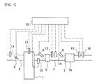
- Fig. 1 is a view showing the schematic construction of intake and exhaust systems of an internal combustion engine according to an embodiment.
- the internal combustion engine 1 is a diesel engine for driving a vehicle.
- An intake passage 2 and an exhaust passage 3 are connected to the internal combustion engine 1.
- the air flow meter 11 serves to detect an amount of intake air sucked into the internal combustion engine 1.
- the throttle valve 9 serves to adjust the amount of intake air sucked into the internal combustion engine 1.
- a first exhaust gas temperature sensor 12 In the exhaust passage 3, there are arranged a first exhaust gas temperature sensor 12, a fuel addition valve 4, a pre-stage catalyst 5, a first NOx sensor 13, a second exhaust gas temperature sensor 14, a reducing agent addition valve 6, an SCRF 7, a second NOx sensor 15, and a third exhaust gas temperature sensor 16, sequentially from the upstream side along the flow of the exhaust gas.
- the pre-stage catalyst 5 is an oxidation catalyst.
- the pre-stage catalyst 5 may be a catalyst other than the oxidation catalyst, as long as it has an oxidation function.
- the pre-stage catalyst 5 may be a three-way catalyst, for example.
- the fuel addition valve 4 adds fuel (HC) into the exhaust gas.
- the SCRF 7 is constructed such that an SCR catalyst 7a is supported by a wall flow type filter which serves to trap particulate matter (PM) in the exhaust gas.
- the SCR catalyst 7a adsorbs ammonia, and reduces the NOx in the exhaust gas by using the ammonia as a reducing agent.
- the SCRF 7 is used in this embodiment, but the filter and the SCR catalyst can also be arranged separately from each other. In cases where the filter and the SCR catalyst are arranged separately from each other, either one of which may be arranged at the upstream side of the other.
- the reducing agent addition valve 6 supplies ammonia into the exhaust gas so as to supply the ammonia as a reducing agent to the SCR catalyst 7a.
- a precursor of ammonia may be supplied, in place of ammonia.
- the precursor of ammonia there can be mentioned urea, for example.
- urea When urea is hydrolyzed by the heat of the exhaust gas, ammonia is generated.
- the ammonia or the precursor thereof may be supplied in any state of gas, liquid or solid. A part of the ammonia is adsorbed to the SCR catalyst 7a. Then, the NOx in the exhaust gas is reduced by means of the ammonia, which has been adsorbed by the SCR catalyst 7a and which acts as a reducing agent.
- the reducing agent addition valve 6 corresponds to a supply device in the present invention.
- the first exhaust gas temperature sensor 12, the second exhaust gas temperature sensor 14, and the third exhaust gas temperature sensor 16 are each a sensor for detecting the temperature of exhaust gas.
- the first exhaust gas temperature sensor 12 detects the temperature of the exhaust gas which flows out from the internal combustion engine 1 or detects the temperature of the exhaust gas which flows into the pre-stage catalyst 5.
- the second exhaust gas temperature sensor 14 detects the temperature of the exhaust gas which flows out from the pre-stage catalyst 5 or detects the temperature of the exhaust gas which flows into the SCRF 7.
- the third exhaust gas temperature sensor 16 detects the temperature of the exhaust gas which flows out from the SCR catalyst 7a.
- the first NOx sensor 13 and the second NOx sensor 15 are each a sensor for detecting the concentration of NOx in the exhaust gas.
- the first NOx sensor 13 detects the concentration of NOx in the exhaust gas flowing into the SCRF 7.
- the second NOx sensor 15 detects the concentration of NOx in the exhaust gas flowing out from the SCR catalyst 7a. All of these sensors are not necessarily required, but some of them can be provided as appropriate.
- a fuel injection valve 17 for directly injecting fuel into a corresponding cylinder.
- An electronic control unit (ECU) 10 is provided in combination with the internal combustion engine 1.
- the ECU 10 is electrically connected to a variety of kinds of sensors such as the air flow meter 11, the first exhaust gas temperature sensor 12, the first NOx sensor 13, the second exhaust gas temperature sensor 14, the second NOx sensor 15, the third exhaust gas temperature sensor 16, and so on. Then, output signals of these various kinds of sensors are inputted to the ECU 10. Further, the ECU 10 estimates the temperature of the pre-stage catalyst 5 based on the output value of the first exhaust gas temperature sensor 12, and the temperature of the SCRF 7 (i.e., the temperature of the SCR catalyst 7a) based on the output value of the second exhaust gas temperature sensor 14.
- the temperature of the pre-stage catalyst 5 can also be estimated based on the output value of the second exhaust gas temperature sensor 14.
- the temperature of the SCRF 7 can also be estimated based on the output value of the third exhaust gas temperature sensor 16.
- the rate of NOx reduction in the SCR catalyst 7a can also be calculated based on the output values of the first NOx sensor 13 and the second NOx sensor 15.
- the fuel addition valve 4, the reducing agent addition valve 6, the throttle valve 9 and the fuel injection valve 17 are electrically connected to the ECU 10. Then, these parts are controlled by means of the ECU 10.
- the ECU 10 corresponds to a control device in the present invention.
- the reducing agent addition valve 6 is arranged at the upstream side of the SCRF 7, so a large amount of PM is contained in the exhaust gas around the reducing agent addition valve 6.
- the amount of reducing agent to be injected per unit time from the reducing agent addition valve 6 can decrease.
- Fig. 2 is a view showing the relation between an instruction value of an amount of supply of the reducing agent, and an actual amount of supply of the reducing agent.
- the instruction value is an amount of supply of the reducing agent calculated by the ECU 10, and can be set as a target value of the amount of supply of the reducing agent.
- "AT NORMAL TIME” represents the case where PM has not adhered to the reducing agent addition valve 6, and "AT THE TIME OF ADHESION OF PM” represents the case where PM has adhered to the reducing agent addition valve 6.
- the amount of supply per unit time of the reducing agent decreases, so that the actual amount of supply of the reducing agent becomes smaller with respect to the instruction value of the amount of supply of the reducing agent. For this reason, there is a fear that the reducing agent may run short in the SCR catalyst 7a.
- Fig. 3 is a view when PM has adhered to the vicinity of a nozzle hole 6a in the reducing agent addition valve 6.
- PM adheres to the vicinity of the nozzle hole 6a it becomes difficult for the reducing agent to flow therethrough, so that the amount of reducing agent passing through the the nozzle hole 6a per unit time will decrease.
- the amount of PM discharge from the internal combustion engine 1 is large, or in cases where the amount of supply of the reducing agent from the reducing agent addition valve 6 is small, it becomes easy for PM to adhere to the reducing agent addition valve 6.
- the PM adhered to the reducing agent addition valve 6 can be removed.
- to make the amount of supply of the reducing agent large includes increasing the amount of supply of the reducing agent per unit time by making the pressure of the reducing agent higher, or increasing the amount of supply of the reducing agent by making the supply period of time of the reducing agent longer.
- the larger the amount of supply of the reducing agent per one time the larger becomes the effect of removing the PM from the reducing agent addition valve 6.
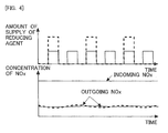
- Fig. 4 is a time chart showing changes over time of the amount of supply of the reducing agent and the concentration of NOx in cases where the temperature of the SCRF 7 is low (e.g., equal to or lower than 250 degrees C).
- a solid line indicates the case where the amount of supply of the reducing agent from the reducing agent addition valve 6 is not caused to increase, and a broken line shows the case where the amount of supply of the reducing agent from the reducing agent addition valve 6 is caused to increase.
- the solid line may also be the case where the ordinary supply of the reducing agent from the reducing agent addition valve 6 is carried out.
- the ordinary supply of the reducing agent is the supply of the reducing agent except when PM is removed from the reducing agent addition valve 6.
- the amount of supply of the reducing agent per one time at the time of the ordinary supply of the reducing agent and the interval of supply of the reducing agent at the time of the ordinary supply of the reducing agent are decided in such a manner that even in the case where the temperature of the SCR catalyst 7a is high, the reducing agent is adsorbed to the SCR catalyst 7a and the rate of NOx reduction falls within an allowable range. For this reason, at the time of the ordinary supply of the reducing agent, the amount of supply of the reducing agent per one time is relatively small, and the interval of supply of the reducing agent is relatively short.
- the reducing agent is adsorbed to the SCR catalyst 7a, even when the amount of supply of the reducing agent per one time and the interval of supply of the reducing agent are made twice with respect to the amount of the ordinary supply of the reducing agent. This is because the amount of supply of the reducing agent per one time and the interval of supply of the reducing agent at the time of the ordinary supply of the reducing agent are decided in such a manner that even in the case where the temperature of the SCR catalyst 7a is high, the reducing agent is adsorbed to the SCR catalyst 7a.
- the amount of supply of the reducing agent per one time is set to be relatively small, and the interval of supply of the reducing agent is set to be relatively short, so that even in the case where the temperature of the SCR catalyst 7a is high, the reducing agent can be adsorbed to the SCR catalyst 7a.
- the amount of supply of the reducing agent is small with respect to the amount of reducing agent able to be adsorbed, and hence, even if the amount of supply of the reducing agent is caused to increase, there is room for the reducing agent to be further adsorbed.
- Fig. 5 is a time chart showing changes over time of the amount of supply of the reducing agent and the concentration of NOx in cases where the temperature of the SCRF 7 is high (e.g., equal to or higher than 250 degrees C, in particular, equal to or higher than 400 degrees C).
- a solid line and a broken line are used with the same meaning as in Fig. 4 .
- the temperature of the SCR catalyst 7a is high, when the amount of supply of the reducing agent per one time and the interval of supply of the reducing agent are doubled, a part of the reducing agent flows out from the SCR catalyst 7a, without being adsorbed to the SCR catalyst 7a.
- the reducing agent runs short in the SCR catalyst 7a, so that the rate of NOx reduction becomes low. That is, in Fig. 5 , the outgoing NOx may increase.
- the rate of NOx reduction becomes high due to an oversupply of the reducing agent. Accordingly, in the case where the temperature of the SCR catalyst 7a is high, when the interval of supply of the reducing agent is made longer at the time of increasing the amount of supply of the reducing agent per one time in order to remove the PM from the reducing agent addition valve 6, there will be a fear that the rate of NOx reduction may become low.
- the amount of supply of the reducing agent per one time from the reducing agent addition valve 6 is made larger than that in the ordinary supply of the reducing agent, and the interval of supply of the reducing agent is made longer than that in the ordinary supply of the reducing agent.
- the amount of supply of the reducing agent per one time from the reducing agent addition valve 6 is made larger than that in the ordinary supply of the reducing agent, but the interval of supply of the reducing agent is made the same as that in the ordinary supply of the reducing agent. That is, in the case where the PM is removed from the reducing agent addition valve 6, the amount of supply of the reducing agent per one time is made to increase from that in the case where the PM is not removed from the reducing agent addition valve 6.
- the interval of supply of the reducing agent is made longer than that when the temperature of the SCR catalyst 7a is equal to or higher than the predetermined temperature.
- the interval of supply of the reducing agent is may also be set as a period of time from the end of the current supply of the reducing agent to the start of the next supply of the reducing agent, or may also set as a period of time from the start of the current supply of the reducing agent to the start of the next supply of the reducing agent.
- the amount of supply of the reducing agent per one time or the interval of supply of the reducing agent is set to be twice with respect to that in the ordinary supply of the reducing agent, but the amount of supply of the reducing agent can be made to increase arbitrarily, as long as it is within a range in which the reducing agent can be adsorbed to the SCR catalyst 7a when the temperature of the SCR catalyst 7a is low. In this case, it is only necessary to change the interval of supply of the reducing agent according to the amount of supply of the reducing agent so that the total amount of the amount of supply of the reducing agent in the predetermined period of time is not changed.
- Fig. 6 is a time chart showing changes over time of the temperature of the SCR catalyst 7a, the amount of PM adhered to the reducing agent addition valve 6 (i.e., the amount of adhesion of PM), and the amount of supply of the reducing agent, in cases where the temperature of the SCR catalyst 7a is less than a predetermined temperature T1.
- the predetermined temperature T1 is a lower limit value of a temperature at which when the amount of supply of the reducing agent per one time and the interval of supply of the reducing agent are made large, there will be a fear that the rate of NOx reduction may decrease or become low.
- a start threshold value Q1 in the amount of adhesion of the PM is an amount of adhesion of the PM at which the processing of removing the PM adhered to the reducing agent addition valve 6 is started.
- an end threshold value Q2 in the amount of adhesion of the PM is an amount of adhesion of the PM at which this processing is ended after the starting of the processing of removing the PM adhered to the reducing agent addition valve 6.
- Fig. 7 is a time chart showing changes over time of the temperature of the SCR catalyst 7a, the amount of PM adhered to the reducing agent addition valve 6 (i.e., the amount of adhesion of PM), the amount of supply of the reducing agent, and the amount of NOx discharge from the internal combustion engine 1, in the case where the temperature of the SCR catalyst 7a is equal to or higher than the predetermined temperature.
- the temperature of the SCRF 7 i.e., the temperature of the SCR catalyst 7a
- T1 the amount of supply of the reducing agent from the reducing agent addition valve 6 is made large, but the interval of supply of the reducing agent is made unchanged.
- the reducing agent when the amount of supply of the reducing agent per one time is made large, the reducing agent may become surplus in the SCR catalyst 7a, if the interval of supply of the reducing agent is not made long. This excessive amount of the reducing agent may flow out from the SCR catalyst 7a. Accordingly, in this embodiment, in the case where the temperature of the SCR catalyst 7a is equal to or higher than the predetermined temperature, when the amount of supply of the reducing agent per one time is made to increase, the amount of NOx discharge from the internal combustion engine 1 may be made to increase. In this case, the amount of NOx discharge is made to increase according to the excessive (surplus) amount of the reducing agent in the SCR catalyst 7a.
- the excessive amount of the reducing agent in the SCR catalyst 7a is caused to react with the NOx, thereby suppressing the reducing agent from flowing out from the SCR catalyst 7a.
- the amount of NOx discharge from the internal combustion engine 1 is decided so that the amount of reducing agent flowing out from the SCR catalyst 7a and the rate of NOx reduction in the SCR catalyst 7a fall within allowable ranges, respectively.
- Fig. 8 is a flow chart showing a flow for decreasing the amount of adhesion of the PM in the reducing agent addition valve 6 according to this embodiment. This flow is carried out by means of the ECU 10 at each predetermined time interval.
- an adhesion amount determination value Qd is calculated.
- the adhesion amount determination value Qd is a value which is in a correlation with the amount of adhesion of the PM in the reducing agent addition valve 6.
- the adhesion amount determination value Qd may also be the amount of adhesion of the PM itself.
- the adhesion amount determination value Qd is associated with the amount of PM discharge Msoot from the internal combustion engine 1 per unit time, the amount of intake air Ga sucked into the internal combustion engine 1 per unit time (i.e., this may also be the flow rate of the exhaust gas), and the temperature of the exhaust gas Tex in the internal combustion engine 1, and hence can be obtained from these values.
- an amount of change ⁇ Qd of the adhesion amount determination value Qd is a value per unit time.
- Fig. 9 is a view showing the relation between the amount of PM discharge Msoot from the internal combustion engine 1, and the amount of change ⁇ Qd of the adhesion amount determination value Qd.
- This relation can be obtained in advance through experiments, simulations, or the like.
- Fig. 10 is a view showing the relation between the amount of intake air Ga in the internal combustion engine 1 and the amount of change ⁇ Qd of the adhesion amount determination value Qd.
- Fig. 10 there is also shown the relation between the amount of intake air Ga in the internal combustion engine 1 and the amount of change ⁇ Qd of the adhesion amount determination value Qd, in the case where the amount of PM discharge Msoot from the internal combustion engine 1 has changed.
- the more the amount of intake air Ga the lower the concentration of PM in the exhaust gas becomes, so the more difficult it becomes for the PM to adhere to the reducing agent addition valve 6. That is, as shown in Fig.
- Fig. 11 is a view showing the relation between the temperature of exhaust gas Tex in the internal combustion engine 1, and the amount of change ⁇ Qd of the adhesion amount determination value Qd.
- the temperature of the exhaust gas Tex is high, a part of high boiling point components in the PM evaporates, so that it becomes difficult for the PM to adhere to the reducing agent addition valve 6.
- the temperature of the exhaust gas Tex is low, it becomes difficult for the high boiling point components in the PM to evaporate, so that it becomes easy for the PM to adhere to the reducing agent addition valve 6. That is, as shown in Fig. 11 , the higher the temperature of the exhaust gas Tex of the internal combustion engine 1 becomes, the smaller the amount of change ⁇ Qd of the adhesion amount determination value Qd becomes. This relation can be obtained in advance through experiments, simulations, or the like.
- the ECU 10 updates the adhesion amount determination value Qd by adding the amount of change ⁇ Qd to the adhesion amount determination value Qd which is calculated from the above relation.
- step S102 it is determined whether the adhesion amount determination value Qd is equal to or larger than the start threshold value Q1. In this step, it is determined whether it is necessary to remove the PM from the reducing agent addition valve 6. In cases where an affirmative determination is made in step S102, the flow or routine advances to step S103, whereas in cases where a negative determination is made, this routine is ended.
- the case in this embodiment where an affirmative determination is made in step S102 corresponds to "the case where a predetermined condition for decreasing the amount of the particulate matter adhered to the supply device is satisfied" in the present invention
- the case in this embodiment where a negative determination is made in step S102 corresponds to "the case where the predetermined condition is not satisfied” in the present invention.
- step S103 it is determined whether the temperature Tscr of the SCRF 7 is less than the predetermined temperature T1.
- the predetermined temperature T1 is the lower limit value of the temperature at which when the amount of supply of the reducing agent per one time and the interval of supply of the reducing agent are made large, there will be a fear that the rate of NOx reduction may decrease or become low.
- This predetermined temperature T1 is 250 degrees C, for example. That is, in this step, it is determined based on the temperature Tscr of the SCRF 7 whether the amount of supply of the reducing agent per one time can be made to increase, and the interval of supply of the reducing agent can be made long.
- the predetermined temperature T1 has been obtained in advance through experiments, simulations or the like.
- step S104 the amount of supply of the reducing agent Qad and the interval of supply of the reducing agent Fad at the time of removing the PM from the reducing agent addition valve 6 are calculated.
- the amount of supply of the reducing agent Qad is an amount of supply of the reducing agent per one time.
- the amount of supply of the reducing agent Qad is larger than an amount of supply of the reducing agent in the case where the supply of the reducing agent for removing the PM from the reducing agent addition valve 6 is not carried out (i.e., the amount of the ordinary supply of the reducing agent).
- the amount of supply of the reducing agent Qad is decided so that the effect of removing the PM falls within an allowable range. Moreover, the amount of supply of the reducing agent Qad calculated in step S104 is made larger than the amount of supply of the reducing agent decided in the ordinary supply of the reducing agent, and the interval of supply of the reducing agent Fad calculated in step S104 is made longer than the interval of supply of the reducing agent decided in the ordinary supply of the reducing agent.
- the lower the temperature of the SCR catalyst 7a the larger the amount of supply of the reducing agent Qad may be made, and the longer the interval of supply of the reducing agent Fad may also be made.
- the amount of supply of the reducing agent Qad and the interval of supply of the reducing agent Fad may be set in such a manner that the rate of NOx reduction does not change from the ordinary supply of the reducing agent. In that case, the total amount of the amount of supply of the reducing agent in the predetermined period of time becomes the same as the total amount of the amount of supply of the reducing agent in the case of assuming that the ordinary supply of the reducing agent has been carried out.
- the amount of supply of the reducing agent Qad and the interval of supply of the reducing agent Fad may be decided in such a manner that the reducing agent can be supplied without excess and deficiency with respect to the amount of NOx discharge from the internal combustion engine 1. These relations may have been decided in advance through experiments, simulations or the like.
- step S105 the adhesion amount determination value Qd is calculated.
- the amount of adhesion of the PM in the reducing agent addition valve 6 is decreased by the supply of the reducing agent.
- the adhesion amount determination value Qd after the amount of adhesion of the PM has been decreased is calculated. For this reason, in this step, first, the amount of change ⁇ Qd of the adhesion amount determination value Qd is calculated. This amount of change ⁇ Qd is a negative value.
- Fig. 12 is a view showing the relation between the amount of supply of the reducing agent Qad per one time, and the amount of change ⁇ Qd of the adhesion amount determination value Qd.
- the larger the amount of supply of the reducing agent Qad per one time the larger becomes the effect of removing the PM from the reducing agent addition valve 6. That is, the larger the amount of supply of the reducing agent Qad per one time, the smaller the amount of change ⁇ Qd of the adhesion amount determination value Qd becomes.
- the amount of change ⁇ Qd of the adhesion amount determination value Qd becomes a negative value.
- the adhesion amount determination value Qd decreases in a gradual manner. Then, the fact that the amount of change ⁇ Qd of the adhesion amount determination value Qd becomes a negative value means a decrease in the amount of adhesion of the PM. This relation can be obtained in advance through experiments, simulations, or the like.
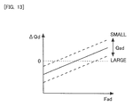
- Fig. 13 is a view showing the relation between the interval of supply of the reducing agent Fad, and the amount of change ⁇ Qd of the adhesion amount determination value Qd.
- Fig. 13 there is also shown the relation between the interval of supply of the reducing agent Fad and the amount of change ⁇ Qd of the adhesion amount determination value Qd, in the case where the amount of supply of the reducing agent Qad per one time has changed.
- the shorter the interval of supply of the reducing agent Fad the larger the effect of removing the PM becomes. That is, as shown in Fig. 13 , the shorter the interval of supply of the reducing agent becomes, the smaller the amount of change ⁇ Qd of the adhesion amount determination value Qd becomes.
- the amount of change ⁇ Qd of the adhesion amount determination value Qd becomes a negative value.
- This relation can be obtained in advance through experiments, simulations, or the like.
- the ECU 10 updates the adhesion amount determination value Qd by adding the amount of change ⁇ Qd to the adhesion amount determination value Qd which is calculated from the above relation.
- step S106 it is determined whether the adhesion amount determination value Qd is less than the end threshold value Q2. In this step, it is determined whether the removal of the PM from the reducing agent addition valve 6 has been completed.
- this step S106 instead of determining whether the adhesion amount determination value Qd is less than the end threshold value Q2, it may be determined whether the adhesion amount determination value Qd is equal to or smaller than the end threshold value Q2. In cases where an affirmative determination is made in step S106, this routine is ended, whereas in cases where a negative determination is made, the routine returns to step S105.
- step S107 the amount of supply of the reducing agent Qad per one time is calculated.
- the amount of supply of the reducing agent Qad per one time is set as a value in which the PM can be removed from the reducing agent addition valve 6.
- the amount of supply of the reducing agent Qad per one time may also be the same value as the amount of supply of the reducing agent Qad which is calculated in step S104.
- a target amount of NOx discharge Mnox is calculated.
- the target amount of NOx discharge Mnox is an amount of NOx which is made to discharge from the internal combustion engine 1 per unit time, at the time of removing the PM from the reducing agent addition valve 6.
- the target amount of NOx discharge Mnox is an amount of NOx which is removed or reduced by the amount of supply of the reducing agent Qad calculated in step S107. That is, by adjusting the amount of supply of the reducing agent to the amount of supply of the reducing agent Qad calculated in step S107 when the amount of NOx discharged from the internal combustion engine 1 becomes the target amount of NOx discharge Mnox, it is possible to supply the reducing agent without excess and deficiency with respect to the amount of NOx discharge.
- the relation between the amount of supply of the reducing agent Qad and the target amount of NOx discharge Mnox can be obtained in advance by experiments, simulations, or the like.
- step S109 the internal combustion engine 1 is controlled according to the target amount of NOx discharge Mnox.
- the amount of NOx discharge from the internal combustion engine 1 changes according to the degree of opening of the throttle valve 9.
- the amount of NOx discharge changes according to the degree of opening of the EGR valve, too.
- the amount of NOx discharge changes according to the degree of opening of the turbo valve, too. Accordingly, the amount of NOx discharge from the internal combustion engine 1 can be controlled by adjusting the degree of opening of the throttle valve 9, the degree of opening of the EGR valve, the degree of opening of the turbo valve, or the like.
- the amount of NOx discharge from the internal combustion engine 1 changes according to the operating state of the internal combustion engine 1 (e.g., the number of engine revolutions per unit time Ne, the amount of fuel injection Qf).
- the degree of opening of the throttle valve 9, etc. which becomes the target amount of NOx discharge Mnox, according to the operating state of the internal combustion engine 1, by means of experiments, simulations, or the like, it is possible to obtain, according to the operating state of the internal combustion engine 1 and the target amount of NOx discharge Mnox, the degree of opening of the throttle valve 9, etc., with which the amount of NOx discharge from the internal combustion engine 1 becomes the target amount of NOx discharge Mnox.
- a well-known technology can also be used for the control to adjust the amount of NOx discharge to the target amount of NOx discharge Mnox.
- step S110 the adhesion amount determination value Qd is calculated, similarly to step S105.
- step S111 it is determined whether the adhesion amount determination value Qd is less than the end threshold value Q2, similarly to step S106. In cases where an affirmative determination is made in step S111, the routine is ended, whereas in cases where a negative determination is made, the routine returns to step S110.
Description
- The present invention relates to an exhaust gas purification apparatus for an internal combustion engine.
- As an exhaust gas purification apparatus arranged in an exhaust passage of an internal combustion engine, there has been developed one in which an NOx selective catalytic reduction catalyst (hereinafter, also referred to as an SCR catalyst) is supported in a filter. The filter serves to trap particulate matter (hereinafter, also referred to as PM) in exhaust gas. The SCR catalyst serves to reduce NOx in the exhaust gas by using ammonia (NH3) as a reducing agent. In the following, such a filter supporting the SCR catalyst thereon is also referred to as an SCRF.
- At the upstream side of the SCRF, there is arranged a reducing agent addition valve which serves to supply ammonia or a precursor of ammonia (e.g., urea) into the exhaust gas. Here, in the past, a filter is provided at the downstream side of the reducing agent addition valve (for example, refer to a first patent literature). On the other hand, in the SCRF, the reducing agent addition valve is provided at the upstream side of the filter. In cases where the reducing agent addition valve is provided at the upstream side of the reducing agent addition valve, a relatively large amount of PM is contained in exhaust gas flowing around the reducing agent addition valve. When the PM in this exhaust gas adheres to the reducing agent addition valve, the opening area of a nozzle (injection) hole of the valve becomes narrow, so there is a fear that an amount of reducing agent per unit time to be supplied from the reducing agent addition valve may be decreased. For this reason, the amount of reducing agent in the SCR catalyst becomes short or insufficient, thus giving rise to a fear that the removal or reduction rate of NOx (hereinafter, also referred to as the rate of NOx removal or reduction) may become low. Here, note that the same can be said in the case of no provision of the filter, too.
- Here, it can be considered that the PM adhered to the reducing agent addition valve is removed by the injection force of the reducing agent, by increasing an amount of supply of the reducing agent per one time at the time of supplying the reducing agent from the reducing agent addition valve. However, an amount of reducing agent, which can be adsorbed to the SCR catalyst, becomes low when the temperature of the SCR catalyst is high, and hence, when the amount of supply of the reducing agent per one time is made to increase, the reducing agent passing through the SCR catalyst will increase. In addition, when the temperature of the SCR catalyst is low, the amount of reducing agent, which can be adsorbed by the SCR catalyst, is relatively large, but there is still a limitation in the amount of reducing agent able to be adsorbed. Moreover, when the PM adhered to the reducing agent addition valve is removed, there is a fear that if the amount of supply of the reducing agent is excessive, the reducing agent may flow out from the SCR catalyst. On the other hand, when the amount of supply of the reducing agent runs short, there is a fear that at the time of removing the PM adhered to the reducing agent addition valve, the rate of NOx reduction may decrease or become low.
- Some references of background art are Japanese Patent Laid-Open Publications Nos.
2011-190720 2012-036839 2013-170570 2013-144938 2009-275667 - The present invention has been made in view of the problems as referred to above, and has for its object to reduce an amount of PM adhered to a reducing agent addition valve, while suppressing a decrease in the rate of NOx removal or reduction.
- In order to solve the above-mentioned problems, the present invention resides in an exhaust gas purification apparatus for an internal combustion engine which is provided with:
- an NOx selective catalytic reduction catalyst that is arranged in an exhaust passage of the internal combustion engine and selectively reduces NOx in an exhaust gas by using ammonia as a reducing agent; and
- a supply device that supplies the reducing agent into the exhaust passage at a location upstream of said NOx selective catalytic reduction catalyst;
- The NOx selective catalytic reduction catalyst (SCR catalyst) may be supported by a filter. In addition, the SCR catalyst and the filter may be arranged at the downstream side of the supply device. The predetermined condition is satisfied in cases where there is a request for removing the particulate matter (PM) from the supply device. For example, in cases where the amount of PM adhered to the supply device or a value having a correlation with the amount of PM adhered to the supply device becomes equal to or more than a threshold value, it may be assumed that the predetermined condition is satisfied. In addition, when the PM adhered to the supply device exceeds an allowable range, for example, it may be assumed that the predetermined condition is satisfied. Moreover, it may be assumed that the predetermined condition is satisfied at every predetermined period of time, for example.
- In cases where the amount of PM adhered to the supply device has become large, the PM adhered to the supply device can be removed by means of the reducing agent, by increasing the amount of supply of the reducing agent per one time. Here, the larger the amount of supply of the reducing agent per one time, the larger becomes the effect of removing the PM. Note that by raising the pressure of the reducing agent, the amount of supply of the reducing agent per one time may also be made larger, or by making longer the supply period of time of the reducing agent, the amount of supply of the reducing agent per one time may also be made larger.
- Here, in the case where the temperature of the SCR catalyst is low, the amount of reducing agent, which can be adsorbed by the SCR catalyst, becomes larger than in the case where the temperature of the SCR catalys is high. That is, the amount of the reducing agent which can be adsorbed by the SCR catalyst changes with the temperature of the SCR catalyst. Even the amount of reducing agent, which can be adsorbed by the SCR catalyst in the case where the temperature of the SCR catalyst is relatively low, may become unable to be adsorbed, in the case where the temperature of the SCR catalyst is relatively high. In order to remove the PM from the supply device, it is effective to increase the amount of supply of the reducing agent per one time, but even if the amount of supply of the reducing agent is increased, there is a fear that when the temperature of the SCR catalyst is high, a part of the reducing agent may pass through the SCR catalyst, without being adsorbed to the SCR catalyst.
- That is, in the case where the temperature of the SCR catalyst is low, the amount of reducing agent, which can be adsorbed to the SCR catalyst, is relatively large, so even if the amount of reducing agent to be supplied to the SCR catalyst is increased, the reducing agent can be caused to be adsorbed to the SCR catalyst. However, there is a limitation on the amount of reducing agent which can be adsorbed by the SCR catalyst. On the other hand, by making longer the interval of supply of the reducing agent, it is possible to suppress the reducing agent from flowing out of the SCR catalyst. In addition, a sufficient amount of reducing agent has been able to be adsorbed to the SCR catalyst, so that even if the interval of supply of the reducing agent is made longer, a decrease in the NOx removal or reduction rate is suppressed. On the other hand, in the case where the temperature of the SCR catalyst is high, the amount of reducing agent, which can be adsorbed by the SCR catalyst, becomes small. For this reason, when the amount of supply of the reducing agent per one time is increased, the reducing agent may flow out of the SCR catalyst, with the SCR catalyst being unable to adsorb the reducing agent to a full or sufficient extent. Accordingly, if the interval of supply of the reducing agent is made long when the temperature of the SCR catalyst is high, such as when the temperature of the SCR catalyst is low, the reducing agent may run short. As a result of this, there is a fear that the removal or reduction rate of NOx may decrease or become low.
- Accordingly, the control device makes the interval of supply of the reducing agent to be supplied from the supply device longer in the case where the temperature of the SCR catalyst is less than the predetermined temperature, than in the case where it is equal to or higher than the predetermined temperature. In the case where the temperature of the SCR catalyst is less than the predetermined temperature, a large amount of reducing agent can be caused to be adsorbed to the SCR catalyst, so that the interval of supply of the reducing agent can be made relatively longer according to an increase in the amount of supply of the reducing agent. On the other hand, in the case where the temperature of the SCR catalyst is equal to or higher than the predetermined temperature, it is difficult to cause a large amount of reducing agent to be adsorbed to the SCR catalyst, so that the interval of supply of the reducing agent is made relatively short. As a result of this, it is possible to suppress the removal or reduction rate of NOx from decreasing or becoming low. The predetermined temperature is a lower limit value of a temperature at which when the amount of supply of the reducing agent per one time and the interval of supply of the reducing agent are made large, there will be a fear that the rate of NOx reduction may decrease or become low. In this manner, it is possible to suppress a decrease in the amount of the reducing agent to be supplied from the supply device, while suppressing the rate of NOx reduction from being decreased.
- In the case where said predetermined condition is satisfied, and in the case where the temperature of said NOx selective catalytic reduction catalyst is equal to or higher than the predetermined temperature, said control device makes the amount of NOx discharged from said internal combustion engine larger according to the increased amount of the reducing agent to be supplied per one time from said supply device, than in the case where said predetermined condition is not satisfied, or in the case where the temperature of said NOx selective catalytic reduction catalyst is less than the predetermined temperature.
- When the amount of reducing agent to be supplied to the SCR catalyst is larger than the amount of reducing agent able to be adsorbed to the SCR catalyst, there is a fear that an excessive amount of the reducing agent may flow out from the SCR catalyst. Accordingly, when the amount of supply of the reducing agent per one time is made large in the case where the temperature of the SCR catalyst is equal to or higher than the predetermined temperature, there is a fear that an excessive amount of the reducing agent may flow out from the SCR catalyst. On the other hand, when the amount of NOx discharged from the internal combustion engine is made to increase according to the increasing amount of supply of the reducing agent, the amount of consumption of the reducing agent in the SCR catalyst can be increased, thus making it possible to decrease the excessive amount of the reducing agent. As a result of this, it is possible to decrease the amount of reducing agent flowing out from the SCR catalyst.
- In the case where said predetermined condition is satisfied, and in the case where the temperature of said NOx selective catalytic reduction catalyst is less than the predetermined temperature, said control device can make the interval of supply of the reducing agent to be supplied from said supply device longer according to said increased amount of the reducing agent to be supplied per one time.
- If the reducing agent is adsorbed to the SCR catalyst even when the amount of supply of the reducing agent per one time has been increased, the interval of supply of the reducing agent can be made long. Here, even if the amount of supply of the reducing agent and the interval of supply of the reducing agent are made to change within a range in which the reducing agent is able to be adsorbed to the SCR catalyst, the rate of NOx reduction will not substantially change, as long as the same amount of the reducing agent as a whole is supplied. For this reason, even if the interval of supply of the reducing agent is increased in accordance with an increase in the amount of supply of the reducing agent per one time, it is possible to maintain the rate of NOx reduction as high as it is.
- In the case where the temperature of said NOx selective catalytic reduction catalyst is equal to or higher than the predetermined temperature, said control device can make the interval of supply of the reducing agent constant irrespective of whether said predetermined condition is satisfied.
- In the case where the temperature of the SCR catalyst is equal to or higher than the predetermined temperature, the amount of reducing agent able to be adsorbed by the SCR catalyst is small, and hence, even if the amount of supply of the reducing agent is increased, the amount of reducing agent to be adsorbed to the SCR catalyst does not increase. For this reason, when the interval of supply of the reducing agent is made long at the time the amount of supply of the reducing agent is increased, a shortage of the reducing agent will be caused. In contrast to this, if the interval of supply of the reducing agent is not changed, even though the amount of supply of the reducing agent is increased, it is possible to suppress the reducing agent from running short. As a result of this, it is possible to suppress a decrease in the rate of NOx reduction.
- According to the present invention, it is possible to decrease the amount of the PM adhered to the reducing agent addition valve, while suppressing the decrease in the rate of NOx reduction.
-
- [
Fig. 1 ] is a view showing the schematic construction of intake and exhaust systems of an internal combustion engine according to an embodiment of the present invention. - [
Fig. 2 ] is a view showing the relation between an instruction value of an amount of supply of a reducing agent, and an actual amount of supply of the reducing agent. - [
Fig. 3 ] is a view when PM has adhered to the vicinity of a nozzle hole in a reducing agent addition valve. - [
Fig. 4 ] is a time chart showing changes over time of the amount of supply of the reducing agent and the concentration of NOx in cases where the temperature of an SCRF is low (e.g., equal to or lower than 250 degrees C). - [
Fig. 5 ] is a time chart showing changes over time of the amount of supply of the reducing agent and the concentration of NOx in cases where the temperature of the SCRF is high (e.g., equal to or higher than 250 degrees C, in particular, equal to or higher than 400 degrees C). - [
Fig. 6 ] is a time chart showing changes over time of the temperature of an SCR catalyst, the amount of PM adhered to the reducing agent addition valve (i.e., the amount of adhesion of PM), and the amount of supply of the reducing agent, in cases where the temperature of the SCR catalyst is less than a predetermined temperature. - [
Fig. 7 ] is a time chart showing changes over time of the temperature of the SCR catalyst, the amount of PM adhered to the reducing agent addition valve (i.e., the amount of adhesion of PM), the amount of supply of the reducing agent, and the amount of NOx discharge from the internal combustion engine, in cases where the temperature of the SCR catalyst is equal to or higher than the predetermined temperature. - [
Fig. 8 ] is a flow chart showing a flow for decreasing the amount of adhesion of PM in the reducing agent addition valve according to the embodiment. - [
Fig. 9 ] is a view showing the relation between an amount of PM discharge Msoot from the internal combustion engine, and an amount of change Δ Qd of an adhesion amount determination value Qd. - [
Fig. 10 ] is a view showing the relation between an amount of intake air Ga in the internal combustion engine, and the amount of change Δ Qd of the adhesion amount determination value Qd. - [
Fig. 11 ] is a view showing the relation between the temperature of exhaust gas Tex in the internal combustion engine, and the amount of change Δ Qd of the adhesion amount determination value Qd. - [
Fig. 12 ] is a view showing the relation between the amount of supply of the reducing agent Qad, and the amount of change Δ Qd of the adhesion amount determination value Qd. - [
Fig. 13 ] is a view showing the relation between the interval of supply of the reducing agent Fad, and the amount of change Δ Qd of the adhesion amount determination value Qd. - Hereinafter, a mode for carrying out the present invention will be exemplarily described in detail based on an embodiment with reference to the attached drawings. However, the dimensions, materials, shapes, relative arrangements and so on of component parts described in the embodiment are not intended to limit the scope of the present invention to these alone in particular as long as there are no specific statements.
- Here, description will be made by taking as an example a case in which an exhaust gas purification apparatus for an internal combustion engine according to the present invention is applied to a diesel engine for driving a vehicle. However, it is to be noted that the internal combustion engine according to the present invention is not limited to a diesel engine, but may be a gasoline engine, etc.
-
Fig. 1 is a view showing the schematic construction of intake and exhaust systems of an internal combustion engine according to an embodiment. Theinternal combustion engine 1 is a diesel engine for driving a vehicle. Anintake passage 2 and anexhaust passage 3 are connected to theinternal combustion engine 1. In theintake passage 2, there are arranged an air flow meter 11 and athrottle valve 9 sequentially from an upstream side along a flow of exhaust gas. The air flow meter 11 serves to detect an amount of intake air sucked into theinternal combustion engine 1. Thethrottle valve 9 serves to adjust the amount of intake air sucked into theinternal combustion engine 1. - In the
exhaust passage 3, there are arranged a first exhaustgas temperature sensor 12, afuel addition valve 4, apre-stage catalyst 5, afirst NOx sensor 13, a second exhaustgas temperature sensor 14, a reducingagent addition valve 6, anSCRF 7, asecond NOx sensor 15, and a third exhaustgas temperature sensor 16, sequentially from the upstream side along the flow of the exhaust gas. - The
pre-stage catalyst 5 is an oxidation catalyst. However, thepre-stage catalyst 5 may be a catalyst other than the oxidation catalyst, as long as it has an oxidation function. Thepre-stage catalyst 5 may be a three-way catalyst, for example. In order to supply fuel to thepre-stage catalyst 5, thefuel addition valve 4 adds fuel (HC) into the exhaust gas. - The
SCRF 7 is constructed such that anSCR catalyst 7a is supported by a wall flow type filter which serves to trap particulate matter (PM) in the exhaust gas. TheSCR catalyst 7a adsorbs ammonia, and reduces the NOx in the exhaust gas by using the ammonia as a reducing agent. Here, note that theSCRF 7 is used in this embodiment, but the filter and the SCR catalyst can also be arranged separately from each other. In cases where the filter and the SCR catalyst are arranged separately from each other, either one of which may be arranged at the upstream side of the other. Moreover, in place of theSCRF 7, there may be provided anSCR catalyst 7a which does not have the function of the filter. - The reducing
agent addition valve 6 supplies ammonia into the exhaust gas so as to supply the ammonia as a reducing agent to theSCR catalyst 7a. Here, note that a precursor of ammonia may be supplied, in place of ammonia. As the precursor of ammonia, there can be mentioned urea, for example. When urea is hydrolyzed by the heat of the exhaust gas, ammonia is generated. The ammonia or the precursor thereof may be supplied in any state of gas, liquid or solid. A part of the ammonia is adsorbed to theSCR catalyst 7a. Then, the NOx in the exhaust gas is reduced by means of the ammonia, which has been adsorbed by theSCR catalyst 7a and which acts as a reducing agent. Here, note that in this embodiment, the reducingagent addition valve 6 corresponds to a supply device in the present invention. - The first exhaust
gas temperature sensor 12, the second exhaustgas temperature sensor 14, and the third exhaustgas temperature sensor 16 are each a sensor for detecting the temperature of exhaust gas. The first exhaustgas temperature sensor 12 detects the temperature of the exhaust gas which flows out from theinternal combustion engine 1 or detects the temperature of the exhaust gas which flows into thepre-stage catalyst 5. The second exhaustgas temperature sensor 14 detects the temperature of the exhaust gas which flows out from thepre-stage catalyst 5 or detects the temperature of the exhaust gas which flows into theSCRF 7. The third exhaustgas temperature sensor 16 detects the temperature of the exhaust gas which flows out from theSCR catalyst 7a. Thefirst NOx sensor 13 and thesecond NOx sensor 15 are each a sensor for detecting the concentration of NOx in the exhaust gas. Thefirst NOx sensor 13 detects the concentration of NOx in the exhaust gas flowing into theSCRF 7. Thesecond NOx sensor 15 detects the concentration of NOx in the exhaust gas flowing out from theSCR catalyst 7a. All of these sensors are not necessarily required, but some of them can be provided as appropriate. - On each of cylinders of the
internal combustion engine 1, there is mounted afuel injection valve 17 for directly injecting fuel into a corresponding cylinder. - An electronic control unit (ECU) 10 is provided in combination with the
internal combustion engine 1. TheECU 10 is electrically connected to a variety of kinds of sensors such as the air flow meter 11, the first exhaustgas temperature sensor 12, thefirst NOx sensor 13, the second exhaustgas temperature sensor 14, thesecond NOx sensor 15, the third exhaustgas temperature sensor 16, and so on. Then, output signals of these various kinds of sensors are inputted to theECU 10. Further, theECU 10 estimates the temperature of thepre-stage catalyst 5 based on the output value of the first exhaustgas temperature sensor 12, and the temperature of the SCRF 7 (i.e., the temperature of theSCR catalyst 7a) based on the output value of the second exhaustgas temperature sensor 14. Here, note that the temperature of thepre-stage catalyst 5 can also be estimated based on the output value of the second exhaustgas temperature sensor 14. Moreover, the temperature of theSCRF 7 can also be estimated based on the output value of the third exhaustgas temperature sensor 16. The rate of NOx reduction in theSCR catalyst 7a can also be calculated based on the output values of thefirst NOx sensor 13 and thesecond NOx sensor 15. - Further, the
fuel addition valve 4, the reducingagent addition valve 6, thethrottle valve 9 and thefuel injection valve 17 are electrically connected to theECU 10. Then, these parts are controlled by means of theECU 10. Here, note that in this embodiment, theECU 10 corresponds to a control device in the present invention. - Here, the reducing
agent addition valve 6 is arranged at the upstream side of theSCRF 7, so a large amount of PM is contained in the exhaust gas around the reducingagent addition valve 6. When the PM adheres to the vicinity of a nozzle hole in the reducingagent addition valve 6, the amount of reducing agent to be injected per unit time from the reducingagent addition valve 6 can decrease. Here, note that in the following, unless otherwise mentioned in particular, in the case where it is said that PM adheres to the reducingagent addition valve 6, it is assumed to include PM adhering to the vicinity of the nozzle hole in the reducingagent addition valve 6. -
Fig. 2 is a view showing the relation between an instruction value of an amount of supply of the reducing agent, and an actual amount of supply of the reducing agent. The instruction value is an amount of supply of the reducing agent calculated by theECU 10, and can be set as a target value of the amount of supply of the reducing agent. "AT NORMAL TIME" represents the case where PM has not adhered to the reducingagent addition valve 6, and "AT THE TIME OF ADHESION OF PM" represents the case where PM has adhered to the reducingagent addition valve 6. When PM adheres to the reducingagent addition valve 6, the amount of supply per unit time of the reducing agent decreases, so that the actual amount of supply of the reducing agent becomes smaller with respect to the instruction value of the amount of supply of the reducing agent. For this reason, there is a fear that the reducing agent may run short in theSCR catalyst 7a. -
Fig. 3 is a view when PM has adhered to the vicinity of anozzle hole 6a in the reducingagent addition valve 6. Thus, when PM adheres to the vicinity of thenozzle hole 6a, it becomes difficult for the reducing agent to flow therethrough, so that the amount of reducing agent passing through the thenozzle hole 6a per unit time will decrease. For example, in cases where the amount of PM discharge from theinternal combustion engine 1 is large, or in cases where the amount of supply of the reducing agent from the reducingagent addition valve 6 is small, it becomes easy for PM to adhere to the reducingagent addition valve 6. - Here, when the amount of supply of the reducing agent from the reducing
agent addition valve 6 is large, the PM adhered to the reducingagent addition valve 6 can be removed. Here, note that to make the amount of supply of the reducing agent large includes increasing the amount of supply of the reducing agent per unit time by making the pressure of the reducing agent higher, or increasing the amount of supply of the reducing agent by making the supply period of time of the reducing agent longer. Here, the larger the amount of supply of the reducing agent per one time, the larger becomes the effect of removing the PM from the reducingagent addition valve 6. - Accordingly, in this embodiment, the PM is removed from the reducing
agent addition valve 6 by increasing the amount of supply of the reducing agent from the reducingagent addition valve 6.Fig. 4 is a time chart showing changes over time of the amount of supply of the reducing agent and the concentration of NOx in cases where the temperature of theSCRF 7 is low (e.g., equal to or lower than 250 degrees C). A solid line indicates the case where the amount of supply of the reducing agent from the reducingagent addition valve 6 is not caused to increase, and a broken line shows the case where the amount of supply of the reducing agent from the reducingagent addition valve 6 is caused to increase. Here, note that the solid line may also be the case where the ordinary supply of the reducing agent from the reducingagent addition valve 6 is carried out. - The ordinary supply of the reducing agent is the supply of the reducing agent except when PM is removed from the reducing
agent addition valve 6. The amount of supply of the reducing agent per one time at the time of the ordinary supply of the reducing agent and the interval of supply of the reducing agent at the time of the ordinary supply of the reducing agent are decided in such a manner that even in the case where the temperature of theSCR catalyst 7a is high, the reducing agent is adsorbed to theSCR catalyst 7a and the rate of NOx reduction falls within an allowable range. For this reason, at the time of the ordinary supply of the reducing agent, the amount of supply of the reducing agent per one time is relatively small, and the interval of supply of the reducing agent is relatively short. - In
Fig. 4 , "INCOMING NOx" indicates the concentration of NOx in the exhaust gas flowing into theSCRF 7, and "OUTGOING NOx" indicates the concentration of NOx in the exhaust gas flowing out from theSCRF 7. InFig. 4 , in the case of the broken line, the amount of supply of the reducing agent per one time is twice, and the interval of supply of the reducing agent is also twice, as compared with the case of the solid line. For this reason, the total amount of the amount of supply of the reducing agent in the case of the solid line in which the supply of the reducing agent is carried out two times is the same as that in the case of the broken line in which the supply of the reducing agent is carried out one time, in the same period of time. In the case of the solid line, and in the case of the broken line, the amount of the outgoing NOx does not substantially change, so the rate of NOx reduction does not substantially change, either. - Here, in the case where the temperature of the
SCR catalyst 7a is low, the reducing agent is adsorbed to theSCR catalyst 7a, even when the amount of supply of the reducing agent per one time and the interval of supply of the reducing agent are made twice with respect to the amount of the ordinary supply of the reducing agent. This is because the amount of supply of the reducing agent per one time and the interval of supply of the reducing agent at the time of the ordinary supply of the reducing agent are decided in such a manner that even in the case where the temperature of theSCR catalyst 7a is high, the reducing agent is adsorbed to theSCR catalyst 7a. That is, in usual, the amount of supply of the reducing agent per one time is set to be relatively small, and the interval of supply of the reducing agent is set to be relatively short, so that even in the case where the temperature of theSCR catalyst 7a is high, the reducing agent can be adsorbed to theSCR catalyst 7a. In that case, in the case where the temperature of theSCR catalyst 7a is low, the amount of supply of the reducing agent is small with respect to the amount of reducing agent able to be adsorbed, and hence, even if the amount of supply of the reducing agent is caused to increase, there is room for the reducing agent to be further adsorbed. Accordingly, even if the amount of supply of the reducing agent per one time and the interval of supply of the reducing agent are caused to increase, it is possible to suppress the reducing agent from flowing out from theSCR catalyst 7a. In contrast to this, when the temperature of theSCR catalyst 7a becomes high, the amount of reducing agent able to be adsorbed decreases. -
Fig. 5 is a time chart showing changes over time of the amount of supply of the reducing agent and the concentration of NOx in cases where the temperature of theSCRF 7 is high (e.g., equal to or higher than 250 degrees C, in particular, equal to or higher than 400 degrees C). A solid line and a broken line are used with the same meaning as inFig. 4 . In the case where the temperature of theSCR catalyst 7a is high, when the amount of supply of the reducing agent per one time and the interval of supply of the reducing agent are doubled, a part of the reducing agent flows out from theSCR catalyst 7a, without being adsorbed to theSCR catalyst 7a. For this reason, the reducing agent runs short in theSCR catalyst 7a, so that the rate of NOx reduction becomes low. That is, inFig. 5 , the outgoing NOx may increase. In addition, at the time of supplying the reducing agent, and immediately after that, the rate of NOx reduction becomes high due to an oversupply of the reducing agent. Accordingly, in the case where the temperature of theSCR catalyst 7a is high, when the interval of supply of the reducing agent is made longer at the time of increasing the amount of supply of the reducing agent per one time in order to remove the PM from the reducingagent addition valve 6, there will be a fear that the rate of NOx reduction may become low. - Accordingly, in this embodiment, in cases where the PM is removed from the reducing
agent addition valve 6, when the temperature of the SCRF 7 (i.e., the temperature of theSCR catalyst 7a) is less than a predetermined temperature, the amount of supply of the reducing agent per one time from the reducingagent addition valve 6 is made larger than that in the ordinary supply of the reducing agent, and the interval of supply of the reducing agent is made longer than that in the ordinary supply of the reducing agent. On the other hand, when the temperature of the SCRF 7 (i.e., the temperature of theSCR catalyst 7a) is equal to or higher than the predetermined temperature, the amount of supply of the reducing agent per one time from the reducingagent addition valve 6 is made larger than that in the ordinary supply of the reducing agent, but the interval of supply of the reducing agent is made the same as that in the ordinary supply of the reducing agent. That is, in the case where the PM is removed from the reducingagent addition valve 6, the amount of supply of the reducing agent per one time is made to increase from that in the case where the PM is not removed from the reducingagent addition valve 6. Moreover, in the case where the PM is removed from the reducingagent addition valve 6, when the temperature of theSCRF 7 is less than the predetermined temperature, the interval of supply of the reducing agent is made longer than that when the temperature of theSCR catalyst 7a is equal to or higher than the predetermined temperature. The interval of supply of the reducing agent is may also be set as a period of time from the end of the current supply of the reducing agent to the start of the next supply of the reducing agent, or may also set as a period of time from the start of the current supply of the reducing agent to the start of the next supply of the reducing agent. Here, note that inFig. 4 andFig. 5 , the amount of supply of the reducing agent per one time or the interval of supply of the reducing agent is set to be twice with respect to that in the ordinary supply of the reducing agent, but the amount of supply of the reducing agent can be made to increase arbitrarily, as long as it is within a range in which the reducing agent can be adsorbed to theSCR catalyst 7a when the temperature of theSCR catalyst 7a is low. In this case, it is only necessary to change the interval of supply of the reducing agent according to the amount of supply of the reducing agent so that the total amount of the amount of supply of the reducing agent in the predetermined period of time is not changed. -
Fig. 6 is a time chart showing changes over time of the temperature of theSCR catalyst 7a, the amount of PM adhered to the reducing agent addition valve 6 (i.e., the amount of adhesion of PM), and the amount of supply of the reducing agent, in cases where the temperature of theSCR catalyst 7a is less than a predetermined temperature T1. The predetermined temperature T1 is a lower limit value of a temperature at which when the amount of supply of the reducing agent per one time and the interval of supply of the reducing agent are made large, there will be a fear that the rate of NOx reduction may decrease or become low. That is, when the temperature of theSCR catalyst 7a is less than the predetermined temperature T1, the amount of supply of the reducing agent per one time and the interval of supply of the reducing agent can be made large. A start threshold value Q1 in the amount of adhesion of the PM is an amount of adhesion of the PM at which the processing of removing the PM adhered to the reducingagent addition valve 6 is started. In addition, an end threshold value Q2 in the amount of adhesion of the PM is an amount of adhesion of the PM at which this processing is ended after the starting of the processing of removing the PM adhered to the reducingagent addition valve 6. That is, when the amount of adhesion of the PM increases to reach the start threshold value Q1 at a time point indicated at TA, the amount of supply of the reducing agent and the interval of supply of the reducing agent are made large, and thereafter, when the amount of adhesion of the PM decreases to reach the end threshold value Q2 at a time point indicated at TB, the amount of supply of the reducing agent and the interval of supply of the reducing agent are returned to the original values, respectively. -
Fig. 7 is a time chart showing changes over time of the temperature of theSCR catalyst 7a, the amount of PM adhered to the reducing agent addition valve 6 (i.e., the amount of adhesion of PM), the amount of supply of the reducing agent, and the amount of NOx discharge from theinternal combustion engine 1, in the case where the temperature of theSCR catalyst 7a is equal to or higher than the predetermined temperature. In the case where the temperature of the SCRF 7 (i.e., the temperature of theSCR catalyst 7a) is equal to or higher than the predetermined temperature T1, the amount of supply of the reducing agent from the reducingagent addition valve 6 is made large, but the interval of supply of the reducing agent is made unchanged. - Here, when the amount of supply of the reducing agent per one time is made large, the reducing agent may become surplus in the
SCR catalyst 7a, if the interval of supply of the reducing agent is not made long. This excessive amount of the reducing agent may flow out from theSCR catalyst 7a. Accordingly, in this embodiment, in the case where the temperature of theSCR catalyst 7a is equal to or higher than the predetermined temperature, when the amount of supply of the reducing agent per one time is made to increase, the amount of NOx discharge from theinternal combustion engine 1 may be made to increase. In this case, the amount of NOx discharge is made to increase according to the excessive (surplus) amount of the reducing agent in theSCR catalyst 7a. That is, by increasing the amount of NOx discharge from theinternal combustion engine 1, the excessive amount of the reducing agent in theSCR catalyst 7a is caused to react with the NOx, thereby suppressing the reducing agent from flowing out from theSCR catalyst 7a. Here, note that when the amount of NOx discharge from theinternal combustion engine 1 is too large or excessive, the rate of NOx reduction in theSCR catalyst 7a will become low, and hence, the amount of NOx discharge from theinternal combustion engine 1 is decided so that the amount of reducing agent flowing out from theSCR catalyst 7a and the rate of NOx reduction in theSCR catalyst 7a fall within allowable ranges, respectively. - In
Fig. 7 , when the amount of adhesion of the PM increases to reach the start threshold value Q1 at the time point indicated at TA, the amount of supply of the reducing agent per one time is increased and at the same time the amount of NOx discharge from theinternal combustion engine 1 is increased, and thereafter, when the amount of adhesion of the PM decreases to reach the end threshold value Q2 at the time point indicated at TB, the amount of supply of the reducing agent and the amount of NOx discharge from theinternal combustion engine 1 are returned to the original values, respectively. - In this manner, by increasing the amount of NOx discharge from the
internal combustion engine 1 according to the increase in the amount of supply of the reducing agent, it is possible to suppress the reducing agent from flowing out from theSCR catalyst 7a. This amount of NOx discharge reacts with the excessive amount of the reducing agent in theSCR catalyst 7a, so there is also substantially no decrease in the rate of NOx reduction. -
Fig. 8 is a flow chart showing a flow for decreasing the amount of adhesion of the PM in the reducingagent addition valve 6 according to this embodiment. This flow is carried out by means of theECU 10 at each predetermined time interval. - In step S101, an adhesion amount determination value Qd is calculated. The adhesion amount determination value Qd is a value which is in a correlation with the amount of adhesion of the PM in the reducing
agent addition valve 6. Here, note that the adhesion amount determination value Qd may also be the amount of adhesion of the PM itself. The adhesion amount determination value Qd is associated with the amount of PM discharge Msoot from theinternal combustion engine 1 per unit time, the amount of intake air Ga sucked into theinternal combustion engine 1 per unit time (i.e., this may also be the flow rate of the exhaust gas), and the temperature of the exhaust gas Tex in theinternal combustion engine 1, and hence can be obtained from these values. Here, it is assumed that an amount of change Δ Qd of the adhesion amount determination value Qd is a value per unit time. -
Fig. 9 is a view showing the relation between the amount of PM discharge Msoot from theinternal combustion engine 1, and the amount of change Δ Qd of the adhesion amount determination value Qd. The more the amount of PM discharge Msoot from theinternal combustion engine 1, the easier it becomes for the PM to adhere to the reducingagent addition valve 6. That is, as shown inFig. 9 , the more the amount of PM discharge Msoot from theinternal combustion engine 1, the larger the amount of change Δ Qd of the adhesion amount determination value Qd becomes. This relation can be obtained in advance through experiments, simulations, or the like. -
Fig. 10 is a view showing the relation between the amount of intake air Ga in theinternal combustion engine 1 and the amount of change Δ Qd of the adhesion amount determination value Qd. InFig. 10 , there is also shown the relation between the amount of intake air Ga in theinternal combustion engine 1 and the amount of change Δ Qd of the adhesion amount determination value Qd, in the case where the amount of PM discharge Msoot from theinternal combustion engine 1 has changed. The more the amount of intake air Ga, the lower the concentration of PM in the exhaust gas becomes, so the more difficult it becomes for the PM to adhere to the reducingagent addition valve 6. That is, as shown inFig. 10 , the more the amount of intake air Ga in theinternal combustion engine 1, the smaller the amount of change Δ Qd of the adhesion amount determination value Qd becomes. Further, the more the amount of PM discharge Msoot from theinternal combustion engine 1 becomes, the larger the amount of change Δ Qd of the adhesion amount determination value Qd becomes. This relation can be obtained in advance through experiments, simulations, or the like. -
Fig. 11 is a view showing the relation between the temperature of exhaust gas Tex in theinternal combustion engine 1, and the amount of change Δ Qd of the adhesion amount determination value Qd. Here, when the temperature of the exhaust gas Tex is high, a part of high boiling point components in the PM evaporates, so that it becomes difficult for the PM to adhere to the reducingagent addition valve 6. On the other hand, when the temperature of the exhaust gas Tex is low, it becomes difficult for the high boiling point components in the PM to evaporate, so that it becomes easy for the PM to adhere to the reducingagent addition valve 6. That is, as shown inFig. 11 , the higher the temperature of the exhaust gas Tex of theinternal combustion engine 1 becomes, the smaller the amount of change Δ Qd of the adhesion amount determination value Qd becomes. This relation can be obtained in advance through experiments, simulations, or the like. - The
ECU 10 updates the adhesion amount determination value Qd by adding the amount of change Δ Qd to the adhesion amount determination value Qd which is calculated from the above relation. - In step S102, it is determined whether the adhesion amount determination value Qd is equal to or larger than the start threshold value Q1. In this step, it is determined whether it is necessary to remove the PM from the reducing
agent addition valve 6. In cases where an affirmative determination is made in step S102, the flow or routine advances to step S103, whereas in cases where a negative determination is made, this routine is ended. Here, note that the case in this embodiment where an affirmative determination is made in step S102 corresponds to "the case where a predetermined condition for decreasing the amount of the particulate matter adhered to the supply device is satisfied" in the present invention, and the case in this embodiment where a negative determination is made in step S102 corresponds to "the case where the predetermined condition is not satisfied" in the present invention. - In step S103, it is determined whether the temperature Tscr of the
SCRF 7 is less than the predetermined temperature T1. As mentioned before, the predetermined temperature T1 is the lower limit value of the temperature at which when the amount of supply of the reducing agent per one time and the interval of supply of the reducing agent are made large, there will be a fear that the rate of NOx reduction may decrease or become low. This predetermined temperature T1 is 250 degrees C, for example. That is, in this step, it is determined based on the temperature Tscr of theSCRF 7 whether the amount of supply of the reducing agent per one time can be made to increase, and the interval of supply of the reducing agent can be made long. The predetermined temperature T1 has been obtained in advance through experiments, simulations or the like. - In cases where an affirmative determination is made in step S103, the routine advances to step S104. In step S104, the amount of supply of the reducing agent Qad and the interval of supply of the reducing agent Fad at the time of removing the PM from the reducing
agent addition valve 6 are calculated. The amount of supply of the reducing agent Qad is an amount of supply of the reducing agent per one time. The amount of supply of the reducing agent Qad is larger than an amount of supply of the reducing agent in the case where the supply of the reducing agent for removing the PM from the reducingagent addition valve 6 is not carried out (i.e., the amount of the ordinary supply of the reducing agent). The amount of supply of the reducing agent Qad is decided so that the effect of removing the PM falls within an allowable range. Moreover, the amount of supply of the reducing agent Qad calculated in step S104 is made larger than the amount of supply of the reducing agent decided in the ordinary supply of the reducing agent, and the interval of supply of the reducing agent Fad calculated in step S104 is made longer than the interval of supply of the reducing agent decided in the ordinary supply of the reducing agent. Here, note that the lower the temperature of theSCR catalyst 7a, the larger the amount of supply of the reducing agent Qad may be made, and the longer the interval of supply of the reducing agent Fad may also be made. In addition, the amount of supply of the reducing agent Qad and the interval of supply of the reducing agent Fad may be set in such a manner that the rate of NOx reduction does not change from the ordinary supply of the reducing agent. In that case, the total amount of the amount of supply of the reducing agent in the predetermined period of time becomes the same as the total amount of the amount of supply of the reducing agent in the case of assuming that the ordinary supply of the reducing agent has been carried out. Moreover, the amount of supply of the reducing agent Qad and the interval of supply of the reducing agent Fad may be decided in such a manner that the reducing agent can be supplied without excess and deficiency with respect to the amount of NOx discharge from theinternal combustion engine 1. These relations may have been decided in advance through experiments, simulations or the like. - In step S105, the adhesion amount determination value Qd is calculated. The amount of adhesion of the PM in the reducing
agent addition valve 6 is decreased by the supply of the reducing agent. In this step, the adhesion amount determination value Qd after the amount of adhesion of the PM has been decreased is calculated. For this reason, in this step, first, the amount of change Δ Qd of the adhesion amount determination value Qd is calculated. This amount of change Δ Qd is a negative value. -
Fig. 12 is a view showing the relation between the amount of supply of the reducing agent Qad per one time, and the amount of change Δ Qd of the adhesion amount determination value Qd. Here, the larger the amount of supply of the reducing agent Qad per one time, the larger becomes the effect of removing the PM from the reducingagent addition valve 6. That is, the larger the amount of supply of the reducing agent Qad per one time, the smaller the amount of change Δ Qd of the adhesion amount determination value Qd becomes. Then, when the amount of supply of the reducing agent Qad per one time increases to a certain extent, the amount of change Δ Qd of the adhesion amount determination value Qd becomes a negative value. That is, when the amount of supply of the reducing agent Qad increases or becomes large, the adhesion amount determination value Qd decreases in a gradual manner. Then, the fact that the amount of change Δ Qd of the adhesion amount determination value Qd becomes a negative value means a decrease in the amount of adhesion of the PM. This relation can be obtained in advance through experiments, simulations, or the like. -
Fig. 13 is a view showing the relation between the interval of supply of the reducing agent Fad, and the amount of change Δ Qd of the adhesion amount determination value Qd. InFig. 13 , there is also shown the relation between the interval of supply of the reducing agent Fad and the amount of change Δ Qd of the adhesion amount determination value Qd, in the case where the amount of supply of the reducing agent Qad per one time has changed. The shorter the interval of supply of the reducing agent Fad, the larger the effect of removing the PM becomes. That is, as shown inFig. 13 , the shorter the interval of supply of the reducing agent becomes, the smaller the amount of change Δ Qd of the adhesion amount determination value Qd becomes. Then, when the interval of supply of the reducing agent Fad becomes shorter to a certain extent, the amount of change Δ Qd of the adhesion amount determination value Qd becomes a negative value. This relation can be obtained in advance through experiments, simulations, or the like. TheECU 10 updates the adhesion amount determination value Qd by adding the amount of change Δ Qd to the adhesion amount determination value Qd which is calculated from the above relation. - In step S106, it is determined whether the adhesion amount determination value Qd is less than the end threshold value Q2. In this step, it is determined whether the removal of the PM from the reducing
agent addition valve 6 has been completed. Here, note that in this step S106, instead of determining whether the adhesion amount determination value Qd is less than the end threshold value Q2, it may be determined whether the adhesion amount determination value Qd is equal to or smaller than the end threshold value Q2. In cases where an affirmative determination is made in step S106, this routine is ended, whereas in cases where a negative determination is made, the routine returns to step S105. - On the other hand, in cases where a negative determination is made in step S103, the routine advances to step S107. In step S107, the amount of supply of the reducing agent Qad per one time is calculated. Here, note that the interval of supply of the reducing agent is not changed from the ordinary supply of the reducing agent. The amount of supply of the reducing agent Qad per one time is set as a value in which the PM can be removed from the reducing
agent addition valve 6. The amount of supply of the reducing agent Qad per one time may also be the same value as the amount of supply of the reducing agent Qad which is calculated in step S104. - In step S108, a target amount of NOx discharge Mnox is calculated. The target amount of NOx discharge Mnox is an amount of NOx which is made to discharge from the
internal combustion engine 1 per unit time, at the time of removing the PM from the reducingagent addition valve 6. The target amount of NOx discharge Mnox is an amount of NOx which is removed or reduced by the amount of supply of the reducing agent Qad calculated in step S107. That is, by adjusting the amount of supply of the reducing agent to the amount of supply of the reducing agent Qad calculated in step S107 when the amount of NOx discharged from theinternal combustion engine 1 becomes the target amount of NOx discharge Mnox, it is possible to supply the reducing agent without excess and deficiency with respect to the amount of NOx discharge. The relation between the amount of supply of the reducing agent Qad and the target amount of NOx discharge Mnox can be obtained in advance by experiments, simulations, or the like. - In step S109, the
internal combustion engine 1 is controlled according to the target amount of NOx discharge Mnox. The amount of NOx discharge from theinternal combustion engine 1 changes according to the degree of opening of thethrottle valve 9. In addition, in cases where provision is made for an EGR device, the amount of NOx discharge changes according to the degree of opening of the EGR valve, too. Moreover, in cases where provision is made for a turbocharger having a turbo valve, the amount of NOx discharge changes according to the degree of opening of the turbo valve, too. Accordingly, the amount of NOx discharge from theinternal combustion engine 1 can be controlled by adjusting the degree of opening of thethrottle valve 9, the degree of opening of the EGR valve, the degree of opening of the turbo valve, or the like. Here, note that the amount of NOx discharge from theinternal combustion engine 1 changes according to the operating state of the internal combustion engine 1 (e.g., the number of engine revolutions per unit time Ne, the amount of fuel injection Qf). By obtaining in advance the degree of opening of thethrottle valve 9, etc., which becomes the target amount of NOx discharge Mnox, according to the operating state of theinternal combustion engine 1, by means of experiments, simulations, or the like, it is possible to obtain, according to the operating state of theinternal combustion engine 1 and the target amount of NOx discharge Mnox, the degree of opening of thethrottle valve 9, etc., with which the amount of NOx discharge from theinternal combustion engine 1 becomes the target amount of NOx discharge Mnox. A well-known technology can also be used for the control to adjust the amount of NOx discharge to the target amount of NOx discharge Mnox. - In step S110, the adhesion amount determination value Qd is calculated, similarly to step S105.
- In step S111, it is determined whether the adhesion amount determination value Qd is less than the end threshold value Q2, similarly to step S106. In cases where an affirmative determination is made in step S111, the routine is ended, whereas in cases where a negative determination is made, the routine returns to step S110.
- As described above, according to this embodiment, it is possible to decrease the amount of the PM adhered to the reducing
agent addition valve 6, while suppressing the decrease of the NOx removal or reduction rate, by adjusting the amount of supply of the reducing agent and the interval of supply of the reducing agent according to the temperature of theSCRF 7, i.e., the temperature of theSCR catalyst 7a. -
- 1
- internal combustion engine
- 2
- intake passage
- 3
- exhaust passage
- 4
- fuel addition valve
- 5
- pre-stage catalyst
- 6
- reducing agent addition valve
- 7
- SCRF
- 7a
- SCR catalyst
- 9
- throttle valve
- 10
- ECU
- 11
- air flow meter
Claims (3)
- An exhaust gas purification apparatus for an internal combustion engine (1), comprising:an NOx selective catalytic reduction catalyst (7a) configured to be arranged in an exhaust passage (3) of the internal combustion engine (1) for selectively reducing NOx in an exhaust gas by using ammonia as a reducing agent; anda supply device (6) for supplying the reducing agent into the exhaust passage (3) at a location upstream of said NOx selective catalytic reduction catalyst (7a);and characterized by comprising also a control device (10) comprising control means adapted to perform a control in such a manner that an amount of the reducing agent supplied from said supply device per one time is made larger in the case where a predetermined condition for decreasing an amount of particulate matter adhered to said supply device (6) is satisfied, than in the case where the predetermined condition is not satisfied, and that in the case where said predetermined condition is satisfied, an interval of supply of the reducing agent from said supply device is made longer in the case where the temperature of said NOx selective catalytic reduction catalyst (7a) is less than a predetermined temperature, than in the case where the temperature of said NOx selective catalytic reduction catalyst (7a) is equal to or higher than the predetermined temperature, and in such a manner that in the case where said predetermined condition is satisfied, and in the case where the temperature of said NOx selective catalytic reduction catalyst (7a) is equal to or higher than the predetermined temperature, the amount of NOx discharged from said internal combustion engine (1) is made larger according to the increased amount of the reducing agent to be supplied per one time from said supply device, than in the case where said predetermined condition is not satisfied, or in the case where the temperature of said NOx selective catalytic reduction catalyst (7a) is less than the predetermined temperature.
- The exhaust gas purification apparatus for an internal combustion engine (1) as set forth in claim 1, wherein said control means are adapted to perform a control such that
in the case where said predetermined condition is satisfied, and in the case where the temperature of said NOx selective catalytic reduction catalyst (7a) is less than the predetermined temperature, the interval of supply of the reducing agent to be supplied from said supply device (6) is made longer according to said increased amount of the reducing agent to be supplied per one time. - The exhaust gas purification apparatus for an internal combustion engine (1) as set forth in claim 1, wherein said control means are adapted to perform a control such that
in the case where the temperature of said NOx selective catalytic reduction catalyst (7a) is equal to or higher than the predetermined temperature, said control device makes the interval of supply of the reducing agent constant, irrespective of whether said predetermined condition is satisfied.
Applications Claiming Priority (1)
| Application Number | Priority Date | Filing Date | Title |
|---|---|---|---|
| JP2014023174A JP5880593B2 (en) | 2014-02-10 | 2014-02-10 | Exhaust gas purification device for internal combustion engine |
Publications (2)
| Publication Number | Publication Date |
|---|---|
| EP2905443A1 EP2905443A1 (en) | 2015-08-12 |
| EP2905443B1 true EP2905443B1 (en) | 2016-11-23 |
Family
ID=52465256
Family Applications (1)
| Application Number | Title | Priority Date | Filing Date |
|---|---|---|---|
| EP15154469.9A Not-in-force EP2905443B1 (en) | 2014-02-10 | 2015-02-10 | Exhaust gas purification apparatus for an internal combustion engine |
Country Status (2)
| Country | Link |
|---|---|
| EP (1) | EP2905443B1 (en) |
| JP (1) | JP5880593B2 (en) |
Families Citing this family (3)
| Publication number | Priority date | Publication date | Assignee | Title |
|---|---|---|---|---|
| JP6430975B2 (en) * | 2016-02-19 | 2018-11-28 | ヤンマー株式会社 | Engine equipment |
| KR102011611B1 (en) * | 2016-02-19 | 2019-10-14 | 얀마 가부시키가이샤 | Engine gear |
| JP6477616B2 (en) * | 2016-06-30 | 2019-03-06 | トヨタ自動車株式会社 | Exhaust purification system cooling system |
Family Cites Families (10)
| Publication number | Priority date | Publication date | Assignee | Title |
|---|---|---|---|---|
| JP2005344682A (en) * | 2004-06-07 | 2005-12-15 | Toyota Motor Corp | Exhaust emission control device |
| JP2008038728A (en) * | 2006-08-04 | 2008-02-21 | Bosch Corp | Reducing agent supply device and control method of reducing agent supply device |
| JP2009275667A (en) * | 2008-05-16 | 2009-11-26 | Toyota Motor Corp | Emission control device of internal combustion engine |
| JP2009287416A (en) * | 2008-05-27 | 2009-12-10 | Denso Corp | Exhaust gas purification controller and exhaust gas purification system using the same |
| JP4598843B2 (en) * | 2008-06-03 | 2010-12-15 | 株式会社日本自動車部品総合研究所 | Exhaust gas purification device for internal combustion engine |
| JP5609175B2 (en) | 2010-03-12 | 2014-10-22 | いすゞ自動車株式会社 | Exhaust gas purification method and apparatus |
| JP2012036839A (en) | 2010-08-06 | 2012-02-23 | Mitsubishi Fuso Truck & Bus Corp | Exhaust emission control device |
| JP5787083B2 (en) * | 2011-11-14 | 2015-09-30 | トヨタ自動車株式会社 | Exhaust gas purification device for internal combustion engine |
| JP2013144938A (en) | 2012-01-13 | 2013-07-25 | Toyota Motor Corp | Exhaust emission control system of internal combustion engine |
| JP2013170570A (en) | 2012-02-23 | 2013-09-02 | Toyota Motor Corp | Abnormality detection system for exhaust emission control device |
-
2014
- 2014-02-10 JP JP2014023174A patent/JP5880593B2/en active Active
-
2015
- 2015-02-10 EP EP15154469.9A patent/EP2905443B1/en not_active Not-in-force
Also Published As
| Publication number | Publication date |
|---|---|
| EP2905443A1 (en) | 2015-08-12 |
| JP5880593B2 (en) | 2016-03-09 |
| JP2015148224A (en) | 2015-08-20 |
Similar Documents
| Publication | Publication Date | Title |
|---|---|---|
| EP2918805B1 (en) | Exhaust gas purification device for internal-combustion engine | |
| US8133444B2 (en) | Exhaust gas purification system for internal combustion engine | |
| EP2278144A1 (en) | NOx SENSOR ABNORMALITY DIAGNOSING APPARATUS AND ABNORMALITY DIAGNOSING METHOD | |
| EP2949894A1 (en) | Exhaust purification device for internal combustion engine | |
| EP2133524B1 (en) | Apparatus for purifying exhaust gas in internal combustion engine | |
| US8540953B2 (en) | Exhaust gas control apparatus and reductant dispensing method for internal combustion engine | |
| EP2479391B1 (en) | Exhaust gas purifying device and method for internal combustion engine | |
| EP2873823B1 (en) | Exhaust gas purification system for an internal combustion engine | |
| US8108154B2 (en) | NOx emission estimation systems and methods | |
| EP2940267B1 (en) | Exhaust gas purification apparatus for internal combustion engine | |
| EP2937534B1 (en) | System for purifying exhaust of internal combustion engine | |
| EP2940265A1 (en) | Exhaust purification system for internal combustion engine | |
| EP2905443B1 (en) | Exhaust gas purification apparatus for an internal combustion engine | |
| WO2013161032A1 (en) | System for determining abnormality in exhaust emission control device for internal combustion engine | |
| EP2284369A1 (en) | Apparatus for checking reducing agent feeder | |
| EP3342998B1 (en) | Exhaust gas purification apparatus for an internal combustion engine | |
| JP2016079852A (en) | Abnormality determination system of exhaust emission control device of internal combustion engine | |
| US9464554B2 (en) | Exhaust gas purification system for internal combustion engine | |
| US9228467B2 (en) | Urea injection controller for a motorized system | |
| EP2868884B1 (en) | Exhaust gas purification system for internal combustion engine | |
| JP6573225B2 (en) | Automatic engine stop control device | |
| EP2891776B1 (en) | Additive supply device for internal combustion engines | |
| JP2018031356A (en) | Exhaust emission control device for internal combustion engine | |
| Ramamurthy et al. | NO x emission estimation systems and methods |
Legal Events
| Date | Code | Title | Description |
|---|---|---|---|
| PUAI | Public reference made under article 153(3) epc to a published international application that has entered the european phase |
Free format text: ORIGINAL CODE: 0009012 |
|
| 17P | Request for examination filed |
Effective date: 20150210 |
|
| AK | Designated contracting states |
Kind code of ref document: A1 Designated state(s): AL AT BE BG CH CY CZ DE DK EE ES FI FR GB GR HR HU IE IS IT LI LT LU LV MC MK MT NL NO PL PT RO RS SE SI SK SM TR |
|
| AX | Request for extension of the european patent |
Extension state: BA ME |
|
| RIC1 | Information provided on ipc code assigned before grant |
Ipc: F01N 9/00 20060101ALI20160512BHEP Ipc: F01N 3/20 20060101AFI20160512BHEP Ipc: F01N 13/00 20100101ALI20160512BHEP |
|
| GRAP | Despatch of communication of intention to grant a patent |
Free format text: ORIGINAL CODE: EPIDOSNIGR1 |
|
| INTG | Intention to grant announced |
Effective date: 20160622 |
|
| GRAS | Grant fee paid |
Free format text: ORIGINAL CODE: EPIDOSNIGR3 |
|
| GRAA | (expected) grant |
Free format text: ORIGINAL CODE: 0009210 |
|
| AK | Designated contracting states |
Kind code of ref document: B1 Designated state(s): AL AT BE BG CH CY CZ DE DK EE ES FI FR GB GR HR HU IE IS IT LI LT LU LV MC MK MT NL NO PL PT RO RS SE SI SK SM TR |
|
| REG | Reference to a national code |
Ref country code: GB Ref legal event code: FG4D |
|
| REG | Reference to a national code |
Ref country code: CH Ref legal event code: EP |
|
| REG | Reference to a national code |
Ref country code: IE Ref legal event code: FG4D |
|
| REG | Reference to a national code |
Ref country code: AT Ref legal event code: REF Ref document number: 848128 Country of ref document: AT Kind code of ref document: T Effective date: 20161215 |
|
| REG | Reference to a national code |
Ref country code: DE Ref legal event code: R096 Ref document number: 602015000766 Country of ref document: DE Ref country code: FR Ref legal event code: PLFP Year of fee payment: 3 |
|
| PG25 | Lapsed in a contracting state [announced via postgrant information from national office to epo] |
Ref country code: LV Free format text: LAPSE BECAUSE OF FAILURE TO SUBMIT A TRANSLATION OF THE DESCRIPTION OR TO PAY THE FEE WITHIN THE PRESCRIBED TIME-LIMIT Effective date: 20161123 |
|
| REG | Reference to a national code |
Ref country code: LT Ref legal event code: MG4D |
|
| REG | Reference to a national code |
Ref country code: NL Ref legal event code: MP Effective date: 20161123 |
|
| REG | Reference to a national code |
Ref country code: AT Ref legal event code: MK05 Ref document number: 848128 Country of ref document: AT Kind code of ref document: T Effective date: 20161123 |
|
| PG25 | Lapsed in a contracting state [announced via postgrant information from national office to epo] |
Ref country code: GR Free format text: LAPSE BECAUSE OF FAILURE TO SUBMIT A TRANSLATION OF THE DESCRIPTION OR TO PAY THE FEE WITHIN THE PRESCRIBED TIME-LIMIT Effective date: 20170224 Ref country code: NL Free format text: LAPSE BECAUSE OF FAILURE TO SUBMIT A TRANSLATION OF THE DESCRIPTION OR TO PAY THE FEE WITHIN THE PRESCRIBED TIME-LIMIT Effective date: 20161123 Ref country code: NO Free format text: LAPSE BECAUSE OF FAILURE TO SUBMIT A TRANSLATION OF THE DESCRIPTION OR TO PAY THE FEE WITHIN THE PRESCRIBED TIME-LIMIT Effective date: 20170223 Ref country code: SE Free format text: LAPSE BECAUSE OF FAILURE TO SUBMIT A TRANSLATION OF THE DESCRIPTION OR TO PAY THE FEE WITHIN THE PRESCRIBED TIME-LIMIT Effective date: 20161123 Ref country code: LT Free format text: LAPSE BECAUSE OF FAILURE TO SUBMIT A TRANSLATION OF THE DESCRIPTION OR TO PAY THE FEE WITHIN THE PRESCRIBED TIME-LIMIT Effective date: 20161123 |
|
| PG25 | Lapsed in a contracting state [announced via postgrant information from national office to epo] |
Ref country code: BE Free format text: LAPSE BECAUSE OF NON-PAYMENT OF DUE FEES Effective date: 20170228 Ref country code: HR Free format text: LAPSE BECAUSE OF FAILURE TO SUBMIT A TRANSLATION OF THE DESCRIPTION OR TO PAY THE FEE WITHIN THE PRESCRIBED TIME-LIMIT Effective date: 20161123 Ref country code: AT Free format text: LAPSE BECAUSE OF FAILURE TO SUBMIT A TRANSLATION OF THE DESCRIPTION OR TO PAY THE FEE WITHIN THE PRESCRIBED TIME-LIMIT Effective date: 20161123 Ref country code: PL Free format text: LAPSE BECAUSE OF FAILURE TO SUBMIT A TRANSLATION OF THE DESCRIPTION OR TO PAY THE FEE WITHIN THE PRESCRIBED TIME-LIMIT Effective date: 20161123 Ref country code: RS Free format text: LAPSE BECAUSE OF FAILURE TO SUBMIT A TRANSLATION OF THE DESCRIPTION OR TO PAY THE FEE WITHIN THE PRESCRIBED TIME-LIMIT Effective date: 20161123 Ref country code: FI Free format text: LAPSE BECAUSE OF FAILURE TO SUBMIT A TRANSLATION OF THE DESCRIPTION OR TO PAY THE FEE WITHIN THE PRESCRIBED TIME-LIMIT Effective date: 20161123 Ref country code: ES Free format text: LAPSE BECAUSE OF FAILURE TO SUBMIT A TRANSLATION OF THE DESCRIPTION OR TO PAY THE FEE WITHIN THE PRESCRIBED TIME-LIMIT Effective date: 20161123 Ref country code: PT Free format text: LAPSE BECAUSE OF FAILURE TO SUBMIT A TRANSLATION OF THE DESCRIPTION OR TO PAY THE FEE WITHIN THE PRESCRIBED TIME-LIMIT Effective date: 20170323 |
|
| PG25 | Lapsed in a contracting state [announced via postgrant information from national office to epo] |
Ref country code: RO Free format text: LAPSE BECAUSE OF FAILURE TO SUBMIT A TRANSLATION OF THE DESCRIPTION OR TO PAY THE FEE WITHIN THE PRESCRIBED TIME-LIMIT Effective date: 20161123 Ref country code: SK Free format text: LAPSE BECAUSE OF FAILURE TO SUBMIT A TRANSLATION OF THE DESCRIPTION OR TO PAY THE FEE WITHIN THE PRESCRIBED TIME-LIMIT Effective date: 20161123 Ref country code: DK Free format text: LAPSE BECAUSE OF FAILURE TO SUBMIT A TRANSLATION OF THE DESCRIPTION OR TO PAY THE FEE WITHIN THE PRESCRIBED TIME-LIMIT Effective date: 20161123 Ref country code: EE Free format text: LAPSE BECAUSE OF FAILURE TO SUBMIT A TRANSLATION OF THE DESCRIPTION OR TO PAY THE FEE WITHIN THE PRESCRIBED TIME-LIMIT Effective date: 20161123 Ref country code: CZ Free format text: LAPSE BECAUSE OF FAILURE TO SUBMIT A TRANSLATION OF THE DESCRIPTION OR TO PAY THE FEE WITHIN THE PRESCRIBED TIME-LIMIT Effective date: 20161123 |
|
| REG | Reference to a national code |
Ref country code: DE Ref legal event code: R097 Ref document number: 602015000766 Country of ref document: DE |
|
| PG25 | Lapsed in a contracting state [announced via postgrant information from national office to epo] |
Ref country code: SM Free format text: LAPSE BECAUSE OF FAILURE TO SUBMIT A TRANSLATION OF THE DESCRIPTION OR TO PAY THE FEE WITHIN THE PRESCRIBED TIME-LIMIT Effective date: 20161123 Ref country code: BE Free format text: LAPSE BECAUSE OF FAILURE TO SUBMIT A TRANSLATION OF THE DESCRIPTION OR TO PAY THE FEE WITHIN THE PRESCRIBED TIME-LIMIT Effective date: 20161123 Ref country code: BG Free format text: LAPSE BECAUSE OF FAILURE TO SUBMIT A TRANSLATION OF THE DESCRIPTION OR TO PAY THE FEE WITHIN THE PRESCRIBED TIME-LIMIT Effective date: 20170223 |
|
| PG25 | Lapsed in a contracting state [announced via postgrant information from national office to epo] |
Ref country code: MC Free format text: LAPSE BECAUSE OF FAILURE TO SUBMIT A TRANSLATION OF THE DESCRIPTION OR TO PAY THE FEE WITHIN THE PRESCRIBED TIME-LIMIT Effective date: 20161123 |
|
| PLBE | No opposition filed within time limit |
Free format text: ORIGINAL CODE: 0009261 |
|
| STAA | Information on the status of an ep patent application or granted ep patent |
Free format text: STATUS: NO OPPOSITION FILED WITHIN TIME LIMIT |
|
| 26N | No opposition filed |
Effective date: 20170824 |
|
| REG | Reference to a national code |
Ref country code: DE Ref legal event code: R084 Ref document number: 602015000766 Country of ref document: DE |
|
| REG | Reference to a national code |
Ref country code: IE Ref legal event code: MM4A |
|
| PG25 | Lapsed in a contracting state [announced via postgrant information from national office to epo] |
Ref country code: SI Free format text: LAPSE BECAUSE OF FAILURE TO SUBMIT A TRANSLATION OF THE DESCRIPTION OR TO PAY THE FEE WITHIN THE PRESCRIBED TIME-LIMIT Effective date: 20161123 |
|
| REG | Reference to a national code |
Ref country code: GB Ref legal event code: 746 Effective date: 20171124 |
|
| PG25 | Lapsed in a contracting state [announced via postgrant information from national office to epo] |
Ref country code: LU Free format text: LAPSE BECAUSE OF NON-PAYMENT OF DUE FEES Effective date: 20170210 |
|
| REG | Reference to a national code |
Ref country code: FR Ref legal event code: PLFP Year of fee payment: 4 |
|
| PG25 | Lapsed in a contracting state [announced via postgrant information from national office to epo] |
Ref country code: IE Free format text: LAPSE BECAUSE OF NON-PAYMENT OF DUE FEES Effective date: 20170210 |
|
| REG | Reference to a national code |
Ref country code: CH Ref legal event code: PL |
|
| PG25 | Lapsed in a contracting state [announced via postgrant information from national office to epo] |
Ref country code: MT Free format text: LAPSE BECAUSE OF NON-PAYMENT OF DUE FEES Effective date: 20170210 |
|
| PG25 | Lapsed in a contracting state [announced via postgrant information from national office to epo] |
Ref country code: LI Free format text: LAPSE BECAUSE OF NON-PAYMENT OF DUE FEES Effective date: 20180228 Ref country code: CH Free format text: LAPSE BECAUSE OF NON-PAYMENT OF DUE FEES Effective date: 20180228 |
|
| PG25 | Lapsed in a contracting state [announced via postgrant information from national office to epo] |
Ref country code: HU Free format text: LAPSE BECAUSE OF FAILURE TO SUBMIT A TRANSLATION OF THE DESCRIPTION OR TO PAY THE FEE WITHIN THE PRESCRIBED TIME-LIMIT; INVALID AB INITIO Effective date: 20150210 |
|
| PG25 | Lapsed in a contracting state [announced via postgrant information from national office to epo] |
Ref country code: CY Free format text: LAPSE BECAUSE OF FAILURE TO SUBMIT A TRANSLATION OF THE DESCRIPTION OR TO PAY THE FEE WITHIN THE PRESCRIBED TIME-LIMIT Effective date: 20161123 |
|
| PG25 | Lapsed in a contracting state [announced via postgrant information from national office to epo] |
Ref country code: MK Free format text: LAPSE BECAUSE OF FAILURE TO SUBMIT A TRANSLATION OF THE DESCRIPTION OR TO PAY THE FEE WITHIN THE PRESCRIBED TIME-LIMIT Effective date: 20161123 |
|
| PG25 | Lapsed in a contracting state [announced via postgrant information from national office to epo] |
Ref country code: TR Free format text: LAPSE BECAUSE OF FAILURE TO SUBMIT A TRANSLATION OF THE DESCRIPTION OR TO PAY THE FEE WITHIN THE PRESCRIBED TIME-LIMIT Effective date: 20161123 |
|
| PG25 | Lapsed in a contracting state [announced via postgrant information from national office to epo] |
Ref country code: AL Free format text: LAPSE BECAUSE OF FAILURE TO SUBMIT A TRANSLATION OF THE DESCRIPTION OR TO PAY THE FEE WITHIN THE PRESCRIBED TIME-LIMIT Effective date: 20161123 Ref country code: IS Free format text: LAPSE BECAUSE OF FAILURE TO SUBMIT A TRANSLATION OF THE DESCRIPTION OR TO PAY THE FEE WITHIN THE PRESCRIBED TIME-LIMIT Effective date: 20170323 |
|
| PGFP | Annual fee paid to national office [announced via postgrant information from national office to epo] |
Ref country code: GB Payment date: 20211230 Year of fee payment: 8 |
|
| PGFP | Annual fee paid to national office [announced via postgrant information from national office to epo] |
Ref country code: DE Payment date: 20211230 Year of fee payment: 8 |
|
| PGFP | Annual fee paid to national office [announced via postgrant information from national office to epo] |
Ref country code: IT Payment date: 20220111 Year of fee payment: 8 Ref country code: FR Payment date: 20220118 Year of fee payment: 8 |
|
| P01 | Opt-out of the competence of the unified patent court (upc) registered |
Effective date: 20230427 |
|
| REG | Reference to a national code |
Ref country code: DE Ref legal event code: R119 Ref document number: 602015000766 Country of ref document: DE |
|
| GBPC | Gb: european patent ceased through non-payment of renewal fee |
Effective date: 20230210 |
|
| PG25 | Lapsed in a contracting state [announced via postgrant information from national office to epo] |
Ref country code: GB Free format text: LAPSE BECAUSE OF NON-PAYMENT OF DUE FEES Effective date: 20230210 |
|
| PG25 | Lapsed in a contracting state [announced via postgrant information from national office to epo] |
Ref country code: IT Free format text: LAPSE BECAUSE OF NON-PAYMENT OF DUE FEES Effective date: 20230210 Ref country code: GB Free format text: LAPSE BECAUSE OF NON-PAYMENT OF DUE FEES Effective date: 20230210 Ref country code: FR Free format text: LAPSE BECAUSE OF NON-PAYMENT OF DUE FEES Effective date: 20230228 Ref country code: DE Free format text: LAPSE BECAUSE OF NON-PAYMENT OF DUE FEES Effective date: 20230901 |