EP2905415B1 - Device and method for applying hooks or clips to the slats of venetian blinds with folded edges provided with abutment gaskets - Google Patents
Device and method for applying hooks or clips to the slats of venetian blinds with folded edges provided with abutment gaskets Download PDFInfo
- Publication number
- EP2905415B1 EP2905415B1 EP15153998.8A EP15153998A EP2905415B1 EP 2905415 B1 EP2905415 B1 EP 2905415B1 EP 15153998 A EP15153998 A EP 15153998A EP 2905415 B1 EP2905415 B1 EP 2905415B1
- Authority
- EP
- European Patent Office
- Prior art keywords
- slat
- matrix
- edge
- seat
- appendage
- Prior art date
- Legal status (The legal status is an assumption and is not a legal conclusion. Google has not performed a legal analysis and makes no representation as to the accuracy of the status listed.)
- Active
Links
Images


Classifications
-
- E—FIXED CONSTRUCTIONS
- E06—DOORS, WINDOWS, SHUTTERS, OR ROLLER BLINDS IN GENERAL; LADDERS
- E06B—FIXED OR MOVABLE CLOSURES FOR OPENINGS IN BUILDINGS, VEHICLES, FENCES OR LIKE ENCLOSURES IN GENERAL, e.g. DOORS, WINDOWS, BLINDS, GATES
- E06B9/00—Screening or protective devices for wall or similar openings, with or without operating or securing mechanisms; Closures of similar construction
- E06B9/24—Screens or other constructions affording protection against light, especially against sunshine; Similar screens for privacy or appearance; Slat blinds
- E06B9/26—Lamellar or like blinds, e.g. venetian blinds
- E06B9/266—Devices or accessories for making or mounting lamellar blinds or parts thereof
-
- E—FIXED CONSTRUCTIONS
- E06—DOORS, WINDOWS, SHUTTERS, OR ROLLER BLINDS IN GENERAL; LADDERS
- E06B—FIXED OR MOVABLE CLOSURES FOR OPENINGS IN BUILDINGS, VEHICLES, FENCES OR LIKE ENCLOSURES IN GENERAL, e.g. DOORS, WINDOWS, BLINDS, GATES
- E06B9/00—Screening or protective devices for wall or similar openings, with or without operating or securing mechanisms; Closures of similar construction
- E06B9/24—Screens or other constructions affording protection against light, especially against sunshine; Similar screens for privacy or appearance; Slat blinds
- E06B9/26—Lamellar or like blinds, e.g. venetian blinds
- E06B9/38—Other details
- E06B9/384—Details of interconnection or interaction of tapes and lamellae
Definitions
- This invention covers a device and method for applying hooks or clips to the slats of Venetian blinds with folded edges provided with abutment gaskets.
- Venetian blinds are constituted by a plurality of slats, arranged parallel to each other and maintained in position by string support structures. These structures are essentially of two types.
- a first type of structure is called "complete ladder", i.e., constituted by two parallel ribs (arranged in the direction of the height of the blinds) and a plurality of crosspieces that connect them to each other at regular distances.
- a slat is associated to each crosspiece, supported (if the crosspiece is single) or inserted (if the crosspiece is multiple).
- a second type of structure is called "separate ladders" or “semi-ladder”, i.e., constituted by two cords separated from each other and each provided with a plurality of string eyelets, distributed at regular distances along the single cord.
- the support cords are positioned in pairs on opposite sides of the slats, generally transversely aligned.
- the cords are associated to the slats at the eyelets using clips or hooks fastened on the side edges of the slats themselves.
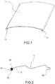
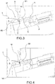
- the slats which may have any section such as C, Z or S-shaped, must have folded edges B (as shown in Figure 1 ) so as to constitute a reinforced zone capable of rigidly supporting a hook or clip.
- FIG. 2 shows a slat with folded edges provided with an abutment gasket S. More in detail, these abutment gaskets S are constituted by an elongated anchoring portion S1, which is inserted inside the folded edge of the slat, and a covering tongue S2, which extends from the anchoring portion S1 to cover the inside of the folded edge and protrude from the slat so as to be interposed between the slat and another slat in the contact zone.
- Devices for the automatic application of the hooks or clips on the folded edges of the slats. These devices are constituted by a central guide A along which the slat L slides, as shown in Figures 3 and 4 . Laterally to such a guide, a matrix M is positioned on each side to lock the folded edge of the slat. This matrix consists of two movable parts, which are coupled together to grip the edge of the slat in a locking seat D.
- a first part M1 of the matrix is arranged on the outside side of the slat and a carries a hook feeder A and a pusher element P.
- the pusher element P is guided to enter inside the locking seat D defined by the two parts of the matrix, carrying in front of itself a single hook to apply to the edge.
- the hooks are positioned placed in front of the head of the pusher element through a chute C connected to the feeder A.
- the second part M2 of the matrix is arranged on the inner side of the slat, below it, as shown in Figures 3 and 4 .
- the purpose of this invention is to totally or partially eliminate the drawbacks of the prior art cited above, by providing a device and a method for applying hooks or clips on slats of Venetian blinds with folded edges provided with abutment gaskets that allows the application of hooks or clips on slats provided with abutment gaskets, leaving the covering tongues of the gaskets completely free from the hooks.
- a further purpose of this invention is to make available a device for applying hooks or clips to the slats of Venetian blinds with folded edges provided with abutment gaskets that is both simple to manage and reliable.
- a further purpose of this invention is to make available a device for applying hooks or clips to the slats of Venetian blinds with folded edges provided with abutment gaskets that is both simple and inexpensive to manufacture.
- 1 indicates a device for applying hooks or clips to the slats of Venetian blinds with folded edges provided with abutment gaskets according to the invention.
- the device 1 allows the application of hooks or clips on slats with folded edges provided with abutment gaskets, leaving the covering tongues of the gaskets completely free from the hooks.
- the device 1 can be inserted into a unit for stacking slats on support semi-ladders for the production of Venetian blinds, and in particular, it can be inserted in the stacking unit covered by patent application No. PD2012A000061 in the name of the same applicant.
- the device 1 for the application of hooks or clips on slats of Venetian blinds comprises a guide (not shown in the attached drawings) which defines a track 2 along which a slat L is positioned.
- the slat L is made to slide to bring different portions of the edge in correspondence to the matrix 10.
- the guide is suitable to position the slat L so that it is placed in one of the two half-spaces 01 and 02 defined by a reference plane m and in such a way that the slat L has its longitudinal edges B1, B2 positioned on this reference plane m.
- the half-space occupied by the slat is indicated with 01 in the attached drawings.
- the above reference plane m is horizontal and the slat L is arranged above the plane, i.e., in the upper half-space 01.
- this reference plane is not horizontal.
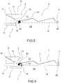
- the device 1 comprises at least a first matrix 10, which is arranged in the vicinity of the track 2 and defines a seat 13 destined to receive a portion of a longitudinal edge B1 of the slat L.
- This matrix 10 comprises at least one access aperture 14 to the seat 13. Through this aperture 14, hooks or clips G are made to enter into the seat 13 to be applied to the edge portion housed therein (as can be seen in the sequence of Figures 5 to 10 ).
- Said seat 13 is formed at the interface between a first portion 11 and a second portion 12 in which the first matrix 10 is divided.
- a first portion 11 of the matrix is provided with a projecting appendage 15 destined to skim the edge B of the slat.
- the first portion 11 is movable so as to move this projecting appendage 15 from a position outside the track 2 (see Figure 5 ) to a position inside the track (see Figure 6 ), so that this appendage 15 crosses the edge B1 of the slat L, remaining in the half-space 02 not occupied by the slat and tangent to the reference plane m (see sequence Figures 5 and 6 ).
- the appendage 15 with its movement from the outside position to the inside position, engages the covering tongue S2, moving the tongue away from the B1 and preventing it from being closed inside the seat 13.
- the device 1 allows distancing a covering tongue S2 of a possible abutment gasket from the edge of a slat before the edge B1 is closed inside the seat 13 for the application of a hook or clip G.
- the covering tongue S2 is moved away from the edge through the interposition of the appendage 15 and, therefore, the application of a hook or clip cannot involve the tongue.
- the appendage 15 of the first portion 11 of the matrix 10 defines, at least partly, the seat 13 in which the edge portion B is locked.
- the appendage 15 is positioned at the interface with the second portion 12 of the matrix.
- This costructional feature is advantageous in that it simplifies the structure of the first portion 11 of the matrix 10.
- the appendage 15 acts as both an interposition element between the edge B1 of the slat and the covering tongue S2, and a delimiting element of the seat 13.
- the first portion 11 of the matrix 10 is moveable in such a way that, once the appendage 10 has been brought into said position inside the track 2, the appendage 15 passes beyond the reference plane m and moves at least partially into the half-space 01 occupied by the slat L, inserting itself between the edge B of the slat and the covering tongue S2 (see sequence Figures 6 and 7 ).
- the appendage 15 (interposed between the edge B1 of the slat L and the tongue S2 of the gasket S) can be brought close to the edge, delimiting the seat 13.
- the device 1 comprises means (not shown in the attached figures) for moving the two portions 11,12 of the matrix between said open position and said closed position.
- movement means are suitable to separately move the two portions 11 and 12 of the matrix 10.
- these movement means may comprise carriages associated to the two portions of the matrix and related actuator means.
- the movement of the two portions 11 and 12 of the matrix 10 is controlled by a logic control unit (not shown in the attached figures) that controls the movement means according to a predefined movement logic of the two portions, and in particular of the first portion 11.
- a logic control unit (not shown in the attached figures) that controls the movement means according to a predefined movement logic of the two portions, and in particular of the first portion 11.
- the reference plane m is preferably horizontal and the slat L is arranged above the plane.
- the first portion 11 of the matrix i.e., the portion that carries the projecting appendage 15 moves and positions itself - at least in some operational phases - below the slat L, and, thus, "internally" to the slat (at least with the projecting appendage 15), while the second portion 12 is maintained “externally” to the slat.
- the first portion 11 of the matrix is always interacting with the inner surface of the folded edge of the slat.
- inner surface means the surface facing towards the centreline of the slat itself, in contrast with the “outer surface”, which is, instead, facing in the opposite direction.
- the application of the hooks or clips takes place in correspondence to the outer surface of the edge of the slat, since the hook or the clip must be placed on the outside edge in order to be associated to a supporting semi-ladder.
- On the inner surface of the edge - in the opposite position to the direction of application of the hook - the hook or the clip only grips to anchor itself firmly to the slat.
- the first portion 11 of the matrix 10 is provided with one or more cavities open on the seat 13, which are suitable to guide the closing of a hook or clip G against the edge portion B.
- the access aperture 14 to the seat 13 is, instead, formed in the second portion 12 of the matrix.
- the device 1 comprises:
- said first matrix 10 is positioned on a first side 2' of the track 2 along which a slat L is positioned.
- the device 1 comprises a second matrix (not shown) structurally and functionally identical to the first at least as described above.
- This second matrix is arranged on a second side 2" of the track opposite to the first side 2'.
- This second matrix allows the application of hooks or clips on an edge B2 of the slat opposite to that on which the first matrix 10 can operate.
- This invention covers a method for applying hooks or clips to the slats of Venetian blinds with folded edges provided with abutment gaskets.
- the method is applied on a device 1 according to this invention.
- the method comprises the following operational steps:
- the appendage 15 In the movement between the outside position and inside position, the appendage 15 is maintained in the half-space 02 not occupied by the slat and tangent to the reference plane m so as to skim the edge. Thanks to this movement, the projecting appendage 15 engages the covering tongue S2 of the gasket S distancing it from the edge (see sequence Figures 5 and 6 ).
- the cycle of steps can then be repeated by opening the seat 13 and sliding the slat along the track L so that a different edge portion is engaged in the matrix 10.
- the invention allows obtaining many advantages in part already described.
- the device and method for the application of hooks or clips on Venetian blind slats allows applying hooks or clips on slats provided with abutment gaskets, leaving the covering tongues of the gaskets completely free from the hooks.
- the covering tongues are distanced from the edges of the slats and maintained outside the matrix during the application of the hooks.
- the device for applying hooks or clips according to the invention is also both simple to manage and reliable.
- the temporary distancing of the tongues is performed by the matrix itself, without the need to provided elements dedicated to this operation. This has the advantage of simplifying construction and ensures greater operational reliability.
- the device 1 according to the invention is simple and inexpensive to manufacture. In fact, for the purposes of the invention, complex or costly technical solutions are not required.
Landscapes
- Engineering & Computer Science (AREA)
- Structural Engineering (AREA)
- Architecture (AREA)
- Civil Engineering (AREA)
- Blinds (AREA)
Priority Applications (2)
| Application Number | Priority Date | Filing Date | Title |
|---|---|---|---|
| PL15153998T PL2905415T3 (pl) | 2014-02-07 | 2015-02-05 | Urządzenie do zakładania haków lub zacisków i sposób zakładania haków lub zacisków na listwy żaluzji o listwach nastawnych z zawiniętymi brzegami wyposażone w uszczelki oporowe |
| SI201530402T SI2905415T1 (sl) | 2014-02-07 | 2015-02-05 | Naprava in način apliciranja kavljev ali sponk na letvice beneških žaluzij z zgibanimi robovi, opremljenimi z opornimi tesnili |
Applications Claiming Priority (1)
| Application Number | Priority Date | Filing Date | Title |
|---|---|---|---|
| ITPD20140020 | 2014-02-07 |
Publications (2)
| Publication Number | Publication Date |
|---|---|
| EP2905415A1 EP2905415A1 (en) | 2015-08-12 |
| EP2905415B1 true EP2905415B1 (en) | 2018-06-27 |
Family
ID=50487018
Family Applications (1)
| Application Number | Title | Priority Date | Filing Date |
|---|---|---|---|
| EP15153998.8A Active EP2905415B1 (en) | 2014-02-07 | 2015-02-05 | Device and method for applying hooks or clips to the slats of venetian blinds with folded edges provided with abutment gaskets |
Country Status (5)
| Country | Link |
|---|---|
| EP (1) | EP2905415B1 (pl) |
| ES (1) | ES2688898T3 (pl) |
| PL (1) | PL2905415T3 (pl) |
| PT (1) | PT2905415T (pl) |
| SI (1) | SI2905415T1 (pl) |
Family Cites Families (2)
| Publication number | Priority date | Publication date | Assignee | Title |
|---|---|---|---|---|
| CH658881A5 (de) * | 1983-03-24 | 1986-12-15 | Griesser Ag | Verfahren und einrichtung zur herstellung des panzers eines lamellenstores. |
| ITPD20120061A1 (it) | 2012-03-02 | 2013-09-03 | Dallan Spa | Unità di impilatura di lamelle su semiscalette di sostegno per la produzione di tende veneziane e metodo di applicazione combinata di ganci e di semiscalette ad una lamella |
-
2015
- 2015-02-05 PL PL15153998T patent/PL2905415T3/pl unknown
- 2015-02-05 SI SI201530402T patent/SI2905415T1/sl unknown
- 2015-02-05 PT PT15153998T patent/PT2905415T/pt unknown
- 2015-02-05 ES ES15153998.8T patent/ES2688898T3/es active Active
- 2015-02-05 EP EP15153998.8A patent/EP2905415B1/en active Active
Non-Patent Citations (1)
| Title |
|---|
| None * |
Also Published As
| Publication number | Publication date |
|---|---|
| EP2905415A1 (en) | 2015-08-12 |
| SI2905415T1 (sl) | 2018-11-30 |
| PT2905415T (pt) | 2018-10-24 |
| PL2905415T3 (pl) | 2018-12-31 |
| ES2688898T3 (es) | 2018-11-07 |
Similar Documents
| Publication | Publication Date | Title |
|---|---|---|
| JP5952970B2 (ja) | 引戸クローザーセット | |
| EP2820221B1 (en) | A retractable covering | |
| US7841376B2 (en) | Window covering safety device | |
| US20110186242A1 (en) | Safety Mechanism for a Window Covering | |
| BR102016018551B1 (pt) | Mecanismo de ajuste de inclinação e cobertura de janela compreendendo o mesmo | |
| NL2019359A (en) | Ladder tape and window blind with the same | |
| EP3237714B1 (en) | Sunshade apparatus and method of assembling a sunshade slat | |
| CA2643183A1 (en) | Cupboard forming a display cabinet with locking for at least one sliding pane | |
| EP2905415B1 (en) | Device and method for applying hooks or clips to the slats of venetian blinds with folded edges provided with abutment gaskets | |
| EP2653646B1 (en) | Stacking unit of slats on support half-ladders for the production of venetian blinds and combined application method of hooks and half-ladders to a slat | |
| EP2599947A2 (en) | Ladder tape for window covering and slat adjusting apparatus using the ladder tape | |
| US10557532B2 (en) | Movable latch housing apparatus | |
| EP2276129B1 (en) | Engageable stretch for cable trays | |
| RS53698B1 (sr) | Jedinica za slaganje lamela na nosećim lestvicama snabdevenim sa duplim poprečnim letvama za izradu venecijanera i postupak za postavljanje lestvica | |
| EP1956181B1 (en) | Blind and its assembling method | |
| ITPD20130354A1 (it) | Unità di impilatura di lamelle su una scaletta di sostegno con traversi doppi per la produzione di tende veneziane e metodo di fissaggio di lamelle su una scaletta con traversi doppi | |
| US20150252613A1 (en) | Fully Open Panel Arrangement with Multiple Guide Rails for Large Window/Door Opening | |
| US20160090778A1 (en) | Endless loop cord safety device | |
| US20240151101A1 (en) | Roman blind with shroud protection | |
| DE102009009983A1 (de) | Jalousieeinheit | |
| JP6082088B2 (ja) | 横型ブラインド | |
| AU2007362201B2 (en) | Attachment link for louvers | |
| JP5164908B2 (ja) | ブラインド | |
| EP3699389B1 (en) | Unit for and method of stacking slats on a support ladder for the production of venetian blinds | |
| CN104913588A (zh) | 用于冰箱的搁物架轨道系统 |
Legal Events
| Date | Code | Title | Description |
|---|---|---|---|
| PUAI | Public reference made under article 153(3) epc to a published international application that has entered the european phase |
Free format text: ORIGINAL CODE: 0009012 |
|
| AK | Designated contracting states |
Kind code of ref document: A1 Designated state(s): AL AT BE BG CH CY CZ DE DK EE ES FI FR GB GR HR HU IE IS IT LI LT LU LV MC MK MT NL NO PL PT RO RS SE SI SK SM TR |
|
| AX | Request for extension of the european patent |
Extension state: BA ME |
|
| 17P | Request for examination filed |
Effective date: 20151221 |
|
| RBV | Designated contracting states (corrected) |
Designated state(s): AL AT BE BG CH CY CZ DE DK EE ES FI FR GB GR HR HU IE IS IT LI LT LU LV MC MK MT NL NO PL PT RO RS SE SI SK SM TR |
|
| GRAP | Despatch of communication of intention to grant a patent |
Free format text: ORIGINAL CODE: EPIDOSNIGR1 |
|
| STAA | Information on the status of an ep patent application or granted ep patent |
Free format text: STATUS: GRANT OF PATENT IS INTENDED |
|
| INTG | Intention to grant announced |
Effective date: 20180130 |
|
| RIN1 | Information on inventor provided before grant (corrected) |
Inventor name: DALLAN, SERGIO |
|
| GRAS | Grant fee paid |
Free format text: ORIGINAL CODE: EPIDOSNIGR3 |
|
| GRAA | (expected) grant |
Free format text: ORIGINAL CODE: 0009210 |
|
| STAA | Information on the status of an ep patent application or granted ep patent |
Free format text: STATUS: THE PATENT HAS BEEN GRANTED |
|
| AK | Designated contracting states |
Kind code of ref document: B1 Designated state(s): AL AT BE BG CH CY CZ DE DK EE ES FI FR GB GR HR HU IE IS IT LI LT LU LV MC MK MT NL NO PL PT RO RS SE SI SK SM TR |
|
| REG | Reference to a national code |
Ref country code: GB Ref legal event code: FG4D |
|
| REG | Reference to a national code |
Ref country code: AT Ref legal event code: REF Ref document number: 1012518 Country of ref document: AT Kind code of ref document: T Effective date: 20180715 |
|
| REG | Reference to a national code |
Ref country code: IE Ref legal event code: FG4D |
|
| REG | Reference to a national code |
Ref country code: DE Ref legal event code: R096 Ref document number: 602015012629 Country of ref document: DE |
|
| REG | Reference to a national code |
Ref country code: CH Ref legal event code: NV Representative=s name: TR-IP CONSULTING LLC, CH |
|
| REG | Reference to a national code |
Ref country code: PT Ref legal event code: SC4A Ref document number: 2905415 Country of ref document: PT Date of ref document: 20181024 Kind code of ref document: T Free format text: AVAILABILITY OF NATIONAL TRANSLATION Effective date: 20180924 |
|
| PG25 | Lapsed in a contracting state [announced via postgrant information from national office to epo] |
Ref country code: LT Free format text: LAPSE BECAUSE OF FAILURE TO SUBMIT A TRANSLATION OF THE DESCRIPTION OR TO PAY THE FEE WITHIN THE PRESCRIBED TIME-LIMIT Effective date: 20180627 Ref country code: FI Free format text: LAPSE BECAUSE OF FAILURE TO SUBMIT A TRANSLATION OF THE DESCRIPTION OR TO PAY THE FEE WITHIN THE PRESCRIBED TIME-LIMIT Effective date: 20180627 Ref country code: BG Free format text: LAPSE BECAUSE OF FAILURE TO SUBMIT A TRANSLATION OF THE DESCRIPTION OR TO PAY THE FEE WITHIN THE PRESCRIBED TIME-LIMIT Effective date: 20180927 Ref country code: NO Free format text: LAPSE BECAUSE OF FAILURE TO SUBMIT A TRANSLATION OF THE DESCRIPTION OR TO PAY THE FEE WITHIN THE PRESCRIBED TIME-LIMIT Effective date: 20180927 Ref country code: SE Free format text: LAPSE BECAUSE OF FAILURE TO SUBMIT A TRANSLATION OF THE DESCRIPTION OR TO PAY THE FEE WITHIN THE PRESCRIBED TIME-LIMIT Effective date: 20180627 |
|
| REG | Reference to a national code |
Ref country code: NL Ref legal event code: MP Effective date: 20180627 |
|
| REG | Reference to a national code |
Ref country code: ES Ref legal event code: FG2A Ref document number: 2688898 Country of ref document: ES Kind code of ref document: T3 Effective date: 20181107 |
|
| REG | Reference to a national code |
Ref country code: LT Ref legal event code: MG4D |
|
| PG25 | Lapsed in a contracting state [announced via postgrant information from national office to epo] |
Ref country code: LV Free format text: LAPSE BECAUSE OF FAILURE TO SUBMIT A TRANSLATION OF THE DESCRIPTION OR TO PAY THE FEE WITHIN THE PRESCRIBED TIME-LIMIT Effective date: 20180627 Ref country code: GR Free format text: LAPSE BECAUSE OF FAILURE TO SUBMIT A TRANSLATION OF THE DESCRIPTION OR TO PAY THE FEE WITHIN THE PRESCRIBED TIME-LIMIT Effective date: 20180928 Ref country code: HR Free format text: LAPSE BECAUSE OF FAILURE TO SUBMIT A TRANSLATION OF THE DESCRIPTION OR TO PAY THE FEE WITHIN THE PRESCRIBED TIME-LIMIT Effective date: 20180627 Ref country code: RS Free format text: LAPSE BECAUSE OF FAILURE TO SUBMIT A TRANSLATION OF THE DESCRIPTION OR TO PAY THE FEE WITHIN THE PRESCRIBED TIME-LIMIT Effective date: 20180627 |
|
| PG25 | Lapsed in a contracting state [announced via postgrant information from national office to epo] |
Ref country code: NL Free format text: LAPSE BECAUSE OF FAILURE TO SUBMIT A TRANSLATION OF THE DESCRIPTION OR TO PAY THE FEE WITHIN THE PRESCRIBED TIME-LIMIT Effective date: 20180627 |
|
| PG25 | Lapsed in a contracting state [announced via postgrant information from national office to epo] |
Ref country code: SK Free format text: LAPSE BECAUSE OF FAILURE TO SUBMIT A TRANSLATION OF THE DESCRIPTION OR TO PAY THE FEE WITHIN THE PRESCRIBED TIME-LIMIT Effective date: 20180627 Ref country code: RO Free format text: LAPSE BECAUSE OF FAILURE TO SUBMIT A TRANSLATION OF THE DESCRIPTION OR TO PAY THE FEE WITHIN THE PRESCRIBED TIME-LIMIT Effective date: 20180627 Ref country code: EE Free format text: LAPSE BECAUSE OF FAILURE TO SUBMIT A TRANSLATION OF THE DESCRIPTION OR TO PAY THE FEE WITHIN THE PRESCRIBED TIME-LIMIT Effective date: 20180627 Ref country code: IS Free format text: LAPSE BECAUSE OF FAILURE TO SUBMIT A TRANSLATION OF THE DESCRIPTION OR TO PAY THE FEE WITHIN THE PRESCRIBED TIME-LIMIT Effective date: 20181027 |
|
| PG25 | Lapsed in a contracting state [announced via postgrant information from national office to epo] |
Ref country code: SM Free format text: LAPSE BECAUSE OF FAILURE TO SUBMIT A TRANSLATION OF THE DESCRIPTION OR TO PAY THE FEE WITHIN THE PRESCRIBED TIME-LIMIT Effective date: 20180627 |
|
| REG | Reference to a national code |
Ref country code: DE Ref legal event code: R097 Ref document number: 602015012629 Country of ref document: DE |
|
| PLBE | No opposition filed within time limit |
Free format text: ORIGINAL CODE: 0009261 |
|
| STAA | Information on the status of an ep patent application or granted ep patent |
Free format text: STATUS: NO OPPOSITION FILED WITHIN TIME LIMIT |
|
| PG25 | Lapsed in a contracting state [announced via postgrant information from national office to epo] |
Ref country code: DK Free format text: LAPSE BECAUSE OF FAILURE TO SUBMIT A TRANSLATION OF THE DESCRIPTION OR TO PAY THE FEE WITHIN THE PRESCRIBED TIME-LIMIT Effective date: 20180627 |
|
| 26N | No opposition filed |
Effective date: 20190328 |
|
| GBPC | Gb: european patent ceased through non-payment of renewal fee |
Effective date: 20190205 |
|
| PG25 | Lapsed in a contracting state [announced via postgrant information from national office to epo] |
Ref country code: LU Free format text: LAPSE BECAUSE OF NON-PAYMENT OF DUE FEES Effective date: 20190205 Ref country code: MC Free format text: LAPSE BECAUSE OF FAILURE TO SUBMIT A TRANSLATION OF THE DESCRIPTION OR TO PAY THE FEE WITHIN THE PRESCRIBED TIME-LIMIT Effective date: 20180627 |
|
| REG | Reference to a national code |
Ref country code: BE Ref legal event code: MM Effective date: 20190228 |
|
| REG | Reference to a national code |
Ref country code: IE Ref legal event code: MM4A |
|
| PG25 | Lapsed in a contracting state [announced via postgrant information from national office to epo] |
Ref country code: AL Free format text: LAPSE BECAUSE OF FAILURE TO SUBMIT A TRANSLATION OF THE DESCRIPTION OR TO PAY THE FEE WITHIN THE PRESCRIBED TIME-LIMIT Effective date: 20180627 |
|
| PG25 | Lapsed in a contracting state [announced via postgrant information from national office to epo] |
Ref country code: IE Free format text: LAPSE BECAUSE OF NON-PAYMENT OF DUE FEES Effective date: 20190205 Ref country code: GB Free format text: LAPSE BECAUSE OF NON-PAYMENT OF DUE FEES Effective date: 20190205 |
|
| REG | Reference to a national code |
Ref country code: CH Ref legal event code: PCAR Free format text: NEW ADDRESS: ROUTE DU COUTSET 18, 1485 NUVILLY (CH) |
|
| PG25 | Lapsed in a contracting state [announced via postgrant information from national office to epo] |
Ref country code: BE Free format text: LAPSE BECAUSE OF NON-PAYMENT OF DUE FEES Effective date: 20190228 |
|
| PG25 | Lapsed in a contracting state [announced via postgrant information from national office to epo] |
Ref country code: TR Free format text: LAPSE BECAUSE OF FAILURE TO SUBMIT A TRANSLATION OF THE DESCRIPTION OR TO PAY THE FEE WITHIN THE PRESCRIBED TIME-LIMIT Effective date: 20180627 |
|
| PG25 | Lapsed in a contracting state [announced via postgrant information from national office to epo] |
Ref country code: MT Free format text: LAPSE BECAUSE OF NON-PAYMENT OF DUE FEES Effective date: 20190205 |
|
| PG25 | Lapsed in a contracting state [announced via postgrant information from national office to epo] |
Ref country code: CY Free format text: LAPSE BECAUSE OF FAILURE TO SUBMIT A TRANSLATION OF THE DESCRIPTION OR TO PAY THE FEE WITHIN THE PRESCRIBED TIME-LIMIT Effective date: 20180627 |
|
| PG25 | Lapsed in a contracting state [announced via postgrant information from national office to epo] |
Ref country code: HU Free format text: LAPSE BECAUSE OF FAILURE TO SUBMIT A TRANSLATION OF THE DESCRIPTION OR TO PAY THE FEE WITHIN THE PRESCRIBED TIME-LIMIT; INVALID AB INITIO Effective date: 20150205 |
|
| REG | Reference to a national code |
Ref country code: AT Ref legal event code: UEP Ref document number: 1012518 Country of ref document: AT Kind code of ref document: T Effective date: 20180627 |
|
| PG25 | Lapsed in a contracting state [announced via postgrant information from national office to epo] |
Ref country code: MK Free format text: LAPSE BECAUSE OF FAILURE TO SUBMIT A TRANSLATION OF THE DESCRIPTION OR TO PAY THE FEE WITHIN THE PRESCRIBED TIME-LIMIT Effective date: 20180627 |
|
| P01 | Opt-out of the competence of the unified patent court (upc) registered |
Effective date: 20230526 |
|
| PGFP | Annual fee paid to national office [announced via postgrant information from national office to epo] |
Ref country code: PT Payment date: 20231221 Year of fee payment: 10 |
|
| PGFP | Annual fee paid to national office [announced via postgrant information from national office to epo] |
Ref country code: PL Payment date: 20231219 Year of fee payment: 10 |
|
| PGFP | Annual fee paid to national office [announced via postgrant information from national office to epo] |
Ref country code: ES Payment date: 20240301 Year of fee payment: 10 |
|
| PGFP | Annual fee paid to national office [announced via postgrant information from national office to epo] |
Ref country code: SI Payment date: 20240125 Year of fee payment: 10 |
|
| PGFP | Annual fee paid to national office [announced via postgrant information from national office to epo] |
Ref country code: FR Payment date: 20240227 Year of fee payment: 10 |
|
| PGFP | Annual fee paid to national office [announced via postgrant information from national office to epo] |
Ref country code: DE Payment date: 20250225 Year of fee payment: 11 |
|
| PGFP | Annual fee paid to national office [announced via postgrant information from national office to epo] |
Ref country code: CH Payment date: 20250301 Year of fee payment: 11 Ref country code: AT Payment date: 20250217 Year of fee payment: 11 |
|
| PGFP | Annual fee paid to national office [announced via postgrant information from national office to epo] |
Ref country code: IT Payment date: 20241114 Year of fee payment: 11 |
|
| PG25 | Lapsed in a contracting state [announced via postgrant information from national office to epo] |
Ref country code: PT Free format text: LAPSE BECAUSE OF NON-PAYMENT OF DUE FEES Effective date: 20250805 |
|
| REG | Reference to a national code |
Ref country code: CH Ref legal event code: R17 Free format text: ST27 STATUS EVENT CODE: U-0-0-R10-R17 (AS PROVIDED BY THE NATIONAL OFFICE) Effective date: 20251103 |
|
| PG25 | Lapsed in a contracting state [announced via postgrant information from national office to epo] |
Ref country code: FR Free format text: LAPSE BECAUSE OF NON-PAYMENT OF DUE FEES Effective date: 20250228 |
|
| PGFP | Annual fee paid to national office [announced via postgrant information from national office to epo] |
Ref country code: CZ Payment date: 20251222 Year of fee payment: 12 |