EP2905399A1 - Movable parking facility - Google Patents
Movable parking facility Download PDFInfo
- Publication number
- EP2905399A1 EP2905399A1 EP13830718.6A EP13830718A EP2905399A1 EP 2905399 A1 EP2905399 A1 EP 2905399A1 EP 13830718 A EP13830718 A EP 13830718A EP 2905399 A1 EP2905399 A1 EP 2905399A1
- Authority
- EP
- European Patent Office
- Prior art keywords
- power
- vehicle
- support portion
- vehicle support
- parking facility
- Prior art date
- Legal status (The legal status is an assumption and is not a legal conclusion. Google has not performed a legal analysis and makes no representation as to the accuracy of the status listed.)
- Granted
Links
Images



Classifications
-
- B—PERFORMING OPERATIONS; TRANSPORTING
- B60—VEHICLES IN GENERAL
- B60L—PROPULSION OF ELECTRICALLY-PROPELLED VEHICLES; SUPPLYING ELECTRIC POWER FOR AUXILIARY EQUIPMENT OF ELECTRICALLY-PROPELLED VEHICLES; ELECTRODYNAMIC BRAKE SYSTEMS FOR VEHICLES IN GENERAL; MAGNETIC SUSPENSION OR LEVITATION FOR VEHICLES; MONITORING OPERATING VARIABLES OF ELECTRICALLY-PROPELLED VEHICLES; ELECTRIC SAFETY DEVICES FOR ELECTRICALLY-PROPELLED VEHICLES
- B60L53/00—Methods of charging batteries, specially adapted for electric vehicles; Charging stations or on-board charging equipment therefor; Exchange of energy storage elements in electric vehicles
- B60L53/10—Methods of charging batteries, specially adapted for electric vehicles; Charging stations or on-board charging equipment therefor; Exchange of energy storage elements in electric vehicles characterised by the energy transfer between the charging station and the vehicle
- B60L53/12—Inductive energy transfer
-
- B—PERFORMING OPERATIONS; TRANSPORTING
- B60—VEHICLES IN GENERAL
- B60L—PROPULSION OF ELECTRICALLY-PROPELLED VEHICLES; SUPPLYING ELECTRIC POWER FOR AUXILIARY EQUIPMENT OF ELECTRICALLY-PROPELLED VEHICLES; ELECTRODYNAMIC BRAKE SYSTEMS FOR VEHICLES IN GENERAL; MAGNETIC SUSPENSION OR LEVITATION FOR VEHICLES; MONITORING OPERATING VARIABLES OF ELECTRICALLY-PROPELLED VEHICLES; ELECTRIC SAFETY DEVICES FOR ELECTRICALLY-PROPELLED VEHICLES
- B60L53/00—Methods of charging batteries, specially adapted for electric vehicles; Charging stations or on-board charging equipment therefor; Exchange of energy storage elements in electric vehicles
- B60L53/10—Methods of charging batteries, specially adapted for electric vehicles; Charging stations or on-board charging equipment therefor; Exchange of energy storage elements in electric vehicles characterised by the energy transfer between the charging station and the vehicle
- B60L53/12—Inductive energy transfer
- B60L53/122—Circuits or methods for driving the primary coil, e.g. supplying electric power to the coil
-
- B—PERFORMING OPERATIONS; TRANSPORTING
- B60—VEHICLES IN GENERAL
- B60L—PROPULSION OF ELECTRICALLY-PROPELLED VEHICLES; SUPPLYING ELECTRIC POWER FOR AUXILIARY EQUIPMENT OF ELECTRICALLY-PROPELLED VEHICLES; ELECTRODYNAMIC BRAKE SYSTEMS FOR VEHICLES IN GENERAL; MAGNETIC SUSPENSION OR LEVITATION FOR VEHICLES; MONITORING OPERATING VARIABLES OF ELECTRICALLY-PROPELLED VEHICLES; ELECTRIC SAFETY DEVICES FOR ELECTRICALLY-PROPELLED VEHICLES
- B60L53/00—Methods of charging batteries, specially adapted for electric vehicles; Charging stations or on-board charging equipment therefor; Exchange of energy storage elements in electric vehicles
- B60L53/10—Methods of charging batteries, specially adapted for electric vehicles; Charging stations or on-board charging equipment therefor; Exchange of energy storage elements in electric vehicles characterised by the energy transfer between the charging station and the vehicle
- B60L53/12—Inductive energy transfer
- B60L53/126—Methods for pairing a vehicle and a charging station, e.g. establishing a one-to-one relation between a wireless power transmitter and a wireless power receiver
-
- B—PERFORMING OPERATIONS; TRANSPORTING
- B60—VEHICLES IN GENERAL
- B60L—PROPULSION OF ELECTRICALLY-PROPELLED VEHICLES; SUPPLYING ELECTRIC POWER FOR AUXILIARY EQUIPMENT OF ELECTRICALLY-PROPELLED VEHICLES; ELECTRODYNAMIC BRAKE SYSTEMS FOR VEHICLES IN GENERAL; MAGNETIC SUSPENSION OR LEVITATION FOR VEHICLES; MONITORING OPERATING VARIABLES OF ELECTRICALLY-PROPELLED VEHICLES; ELECTRIC SAFETY DEVICES FOR ELECTRICALLY-PROPELLED VEHICLES
- B60L53/00—Methods of charging batteries, specially adapted for electric vehicles; Charging stations or on-board charging equipment therefor; Exchange of energy storage elements in electric vehicles
- B60L53/30—Constructional details of charging stations
- B60L53/305—Communication interfaces
-
- B—PERFORMING OPERATIONS; TRANSPORTING
- B60—VEHICLES IN GENERAL
- B60L—PROPULSION OF ELECTRICALLY-PROPELLED VEHICLES; SUPPLYING ELECTRIC POWER FOR AUXILIARY EQUIPMENT OF ELECTRICALLY-PROPELLED VEHICLES; ELECTRODYNAMIC BRAKE SYSTEMS FOR VEHICLES IN GENERAL; MAGNETIC SUSPENSION OR LEVITATION FOR VEHICLES; MONITORING OPERATING VARIABLES OF ELECTRICALLY-PROPELLED VEHICLES; ELECTRIC SAFETY DEVICES FOR ELECTRICALLY-PROPELLED VEHICLES
- B60L53/00—Methods of charging batteries, specially adapted for electric vehicles; Charging stations or on-board charging equipment therefor; Exchange of energy storage elements in electric vehicles
- B60L53/30—Constructional details of charging stations
- B60L53/35—Means for automatic or assisted adjustment of the relative position of charging devices and vehicles
- B60L53/36—Means for automatic or assisted adjustment of the relative position of charging devices and vehicles by positioning the vehicle
-
- B—PERFORMING OPERATIONS; TRANSPORTING
- B60—VEHICLES IN GENERAL
- B60L—PROPULSION OF ELECTRICALLY-PROPELLED VEHICLES; SUPPLYING ELECTRIC POWER FOR AUXILIARY EQUIPMENT OF ELECTRICALLY-PROPELLED VEHICLES; ELECTRODYNAMIC BRAKE SYSTEMS FOR VEHICLES IN GENERAL; MAGNETIC SUSPENSION OR LEVITATION FOR VEHICLES; MONITORING OPERATING VARIABLES OF ELECTRICALLY-PROPELLED VEHICLES; ELECTRIC SAFETY DEVICES FOR ELECTRICALLY-PROPELLED VEHICLES
- B60L53/00—Methods of charging batteries, specially adapted for electric vehicles; Charging stations or on-board charging equipment therefor; Exchange of energy storage elements in electric vehicles
- B60L53/30—Constructional details of charging stations
- B60L53/35—Means for automatic or assisted adjustment of the relative position of charging devices and vehicles
- B60L53/38—Means for automatic or assisted adjustment of the relative position of charging devices and vehicles specially adapted for charging by inductive energy transfer
-
- E—FIXED CONSTRUCTIONS
- E04—BUILDING
- E04H—BUILDINGS OR LIKE STRUCTURES FOR PARTICULAR PURPOSES; SWIMMING OR SPLASH BATHS OR POOLS; MASTS; FENCING; TENTS OR CANOPIES, IN GENERAL
- E04H6/00—Buildings for parking cars, rolling-stock, aircraft, vessels or like vehicles, e.g. garages
- E04H6/08—Garages for many vehicles
- E04H6/12—Garages for many vehicles with mechanical means for shifting or lifting vehicles
- E04H6/18—Garages for many vehicles with mechanical means for shifting or lifting vehicles with means for transport in vertical direction only or independently in vertical and horizontal directions
- E04H6/22—Garages for many vehicles with mechanical means for shifting or lifting vehicles with means for transport in vertical direction only or independently in vertical and horizontal directions characterised by use of movable platforms for horizontal transport, i.e. cars being permanently parked on palettes
-
- E—FIXED CONSTRUCTIONS
- E04—BUILDING
- E04H—BUILDINGS OR LIKE STRUCTURES FOR PARTICULAR PURPOSES; SWIMMING OR SPLASH BATHS OR POOLS; MASTS; FENCING; TENTS OR CANOPIES, IN GENERAL
- E04H6/00—Buildings for parking cars, rolling-stock, aircraft, vessels or like vehicles, e.g. garages
- E04H6/08—Garages for many vehicles
- E04H6/12—Garages for many vehicles with mechanical means for shifting or lifting vehicles
- E04H6/18—Garages for many vehicles with mechanical means for shifting or lifting vehicles with means for transport in vertical direction only or independently in vertical and horizontal directions
- E04H6/22—Garages for many vehicles with mechanical means for shifting or lifting vehicles with means for transport in vertical direction only or independently in vertical and horizontal directions characterised by use of movable platforms for horizontal transport, i.e. cars being permanently parked on palettes
- E04H6/225—Garages for many vehicles with mechanical means for shifting or lifting vehicles with means for transport in vertical direction only or independently in vertical and horizontal directions characterised by use of movable platforms for horizontal transport, i.e. cars being permanently parked on palettes without transverse movement of the parking palette after leaving the transfer means
-
- E—FIXED CONSTRUCTIONS
- E04—BUILDING
- E04H—BUILDINGS OR LIKE STRUCTURES FOR PARTICULAR PURPOSES; SWIMMING OR SPLASH BATHS OR POOLS; MASTS; FENCING; TENTS OR CANOPIES, IN GENERAL
- E04H6/00—Buildings for parking cars, rolling-stock, aircraft, vessels or like vehicles, e.g. garages
- E04H6/08—Garages for many vehicles
- E04H6/12—Garages for many vehicles with mechanical means for shifting or lifting vehicles
- E04H6/30—Garages for many vehicles with mechanical means for shifting or lifting vehicles with means for transport in horizontal direction only
- E04H6/34—Garages for many vehicles with mechanical means for shifting or lifting vehicles with means for transport in horizontal direction only characterised by use of movable platforms
-
- E—FIXED CONSTRUCTIONS
- E04—BUILDING
- E04H—BUILDINGS OR LIKE STRUCTURES FOR PARTICULAR PURPOSES; SWIMMING OR SPLASH BATHS OR POOLS; MASTS; FENCING; TENTS OR CANOPIES, IN GENERAL
- E04H6/00—Buildings for parking cars, rolling-stock, aircraft, vessels or like vehicles, e.g. garages
- E04H6/42—Devices or arrangements peculiar to garages, not covered elsewhere, e.g. securing devices, safety devices, monitoring and operating schemes; centering devices
-
- H—ELECTRICITY
- H02—GENERATION; CONVERSION OR DISTRIBUTION OF ELECTRIC POWER
- H02J—ELECTRIC POWER NETWORKS; CIRCUIT ARRANGEMENTS OR SYSTEMS FOR SUPPLYING OR DISTRIBUTING ELECTRIC POWER; SYSTEMS FOR STORING ELECTRIC ENERGY
- H02J50/00—Circuit arrangements or systems for wireless supply or distribution of electric power
- H02J50/10—Circuit arrangements or systems for wireless supply or distribution of electric power using inductive coupling
- H02J50/12—Circuit arrangements or systems for wireless supply or distribution of electric power using inductive coupling of the resonant type
-
- H—ELECTRICITY
- H02—GENERATION; CONVERSION OR DISTRIBUTION OF ELECTRIC POWER
- H02J—ELECTRIC POWER NETWORKS; CIRCUIT ARRANGEMENTS OR SYSTEMS FOR SUPPLYING OR DISTRIBUTING ELECTRIC POWER; SYSTEMS FOR STORING ELECTRIC ENERGY
- H02J50/00—Circuit arrangements or systems for wireless supply or distribution of electric power
- H02J50/40—Circuit arrangements or systems for wireless supply or distribution of electric power using two or more transmitting or receiving devices
- H02J50/402—Circuit arrangements or systems for wireless supply or distribution of electric power using two or more transmitting or receiving devices the two or more transmitting or the two or more receiving devices being integrated in the same unit, e.g. power mats with several coils or antennas with several sub-antennas
-
- H—ELECTRICITY
- H02—GENERATION; CONVERSION OR DISTRIBUTION OF ELECTRIC POWER
- H02J—ELECTRIC POWER NETWORKS; CIRCUIT ARRANGEMENTS OR SYSTEMS FOR SUPPLYING OR DISTRIBUTING ELECTRIC POWER; SYSTEMS FOR STORING ELECTRIC ENERGY
- H02J50/00—Circuit arrangements or systems for wireless supply or distribution of electric power
- H02J50/90—Circuit arrangements or systems for wireless supply or distribution of electric power involving detection or optimisation of position, e.g. alignment
-
- H—ELECTRICITY
- H02—GENERATION; CONVERSION OR DISTRIBUTION OF ELECTRIC POWER
- H02J—ELECTRIC POWER NETWORKS; CIRCUIT ARRANGEMENTS OR SYSTEMS FOR SUPPLYING OR DISTRIBUTING ELECTRIC POWER; SYSTEMS FOR STORING ELECTRIC ENERGY
- H02J7/00—Circuit arrangements for charging or discharging batteries or for supplying loads from batteries
- H02J7/70—Circuit arrangements for charging or discharging batteries or for supplying loads from batteries characterised by the mechanical construction
- H02J7/731—Circuit arrangements for charging or discharging batteries or for supplying loads from batteries characterised by the mechanical construction specially adapted for holding portable devices containing batteries
-
- H—ELECTRICITY
- H01—ELECTRIC ELEMENTS
- H01M—PROCESSES OR MEANS, e.g. BATTERIES, FOR THE DIRECT CONVERSION OF CHEMICAL ENERGY INTO ELECTRICAL ENERGY
- H01M10/00—Secondary cells; Manufacture thereof
- H01M10/42—Methods or arrangements for servicing or maintenance of secondary cells or secondary half-cells
- H01M10/46—Accumulators structurally combined with charging apparatus
-
- H—ELECTRICITY
- H02—GENERATION; CONVERSION OR DISTRIBUTION OF ELECTRIC POWER
- H02J—ELECTRIC POWER NETWORKS; CIRCUIT ARRANGEMENTS OR SYSTEMS FOR SUPPLYING OR DISTRIBUTING ELECTRIC POWER; SYSTEMS FOR STORING ELECTRIC ENERGY
- H02J2105/00—Networks for supplying or distributing electric power characterised by their spatial reach or by the load
- H02J2105/30—Networks for supplying or distributing electric power characterised by their spatial reach or by the load the load networks being external to vehicles, i.e. exchanging power with vehicles
- H02J2105/33—Networks for supplying or distributing electric power characterised by their spatial reach or by the load the load networks being external to vehicles, i.e. exchanging power with vehicles exchanging power with road vehicles
- H02J2105/37—Networks for supplying or distributing electric power characterised by their spatial reach or by the load the load networks being external to vehicles, i.e. exchanging power with vehicles exchanging power with road vehicles exchanging power with electric vehicles [EV] or with hybrid electric vehicles [HEV]
-
- H—ELECTRICITY
- H02—GENERATION; CONVERSION OR DISTRIBUTION OF ELECTRIC POWER
- H02J—ELECTRIC POWER NETWORKS; CIRCUIT ARRANGEMENTS OR SYSTEMS FOR SUPPLYING OR DISTRIBUTING ELECTRIC POWER; SYSTEMS FOR STORING ELECTRIC ENERGY
- H02J7/00—Circuit arrangements for charging or discharging batteries or for supplying loads from batteries
- H02J7/50—Circuit arrangements for charging or discharging batteries or for supplying loads from batteries acting upon multiple batteries simultaneously or sequentially
-
- Y—GENERAL TAGGING OF NEW TECHNOLOGICAL DEVELOPMENTS; GENERAL TAGGING OF CROSS-SECTIONAL TECHNOLOGIES SPANNING OVER SEVERAL SECTIONS OF THE IPC; TECHNICAL SUBJECTS COVERED BY FORMER USPC CROSS-REFERENCE ART COLLECTIONS [XRACs] AND DIGESTS
- Y02—TECHNOLOGIES OR APPLICATIONS FOR MITIGATION OR ADAPTATION AGAINST CLIMATE CHANGE
- Y02E—REDUCTION OF GREENHOUSE GAS [GHG] EMISSIONS, RELATED TO ENERGY GENERATION, TRANSMISSION OR DISTRIBUTION
- Y02E60/00—Enabling technologies; Technologies with a potential or indirect contribution to GHG emissions mitigation
- Y02E60/10—Energy storage using batteries
-
- Y—GENERAL TAGGING OF NEW TECHNOLOGICAL DEVELOPMENTS; GENERAL TAGGING OF CROSS-SECTIONAL TECHNOLOGIES SPANNING OVER SEVERAL SECTIONS OF THE IPC; TECHNICAL SUBJECTS COVERED BY FORMER USPC CROSS-REFERENCE ART COLLECTIONS [XRACs] AND DIGESTS
- Y02—TECHNOLOGIES OR APPLICATIONS FOR MITIGATION OR ADAPTATION AGAINST CLIMATE CHANGE
- Y02T—CLIMATE CHANGE MITIGATION TECHNOLOGIES RELATED TO TRANSPORTATION
- Y02T10/00—Road transport of goods or passengers
- Y02T10/60—Other road transportation technologies with climate change mitigation effect
- Y02T10/70—Energy storage systems for electromobility, e.g. batteries
-
- Y—GENERAL TAGGING OF NEW TECHNOLOGICAL DEVELOPMENTS; GENERAL TAGGING OF CROSS-SECTIONAL TECHNOLOGIES SPANNING OVER SEVERAL SECTIONS OF THE IPC; TECHNICAL SUBJECTS COVERED BY FORMER USPC CROSS-REFERENCE ART COLLECTIONS [XRACs] AND DIGESTS
- Y02—TECHNOLOGIES OR APPLICATIONS FOR MITIGATION OR ADAPTATION AGAINST CLIMATE CHANGE
- Y02T—CLIMATE CHANGE MITIGATION TECHNOLOGIES RELATED TO TRANSPORTATION
- Y02T10/00—Road transport of goods or passengers
- Y02T10/60—Other road transportation technologies with climate change mitigation effect
- Y02T10/7072—Electromobility specific charging systems or methods for batteries, ultracapacitors, supercapacitors or double-layer capacitors
-
- Y—GENERAL TAGGING OF NEW TECHNOLOGICAL DEVELOPMENTS; GENERAL TAGGING OF CROSS-SECTIONAL TECHNOLOGIES SPANNING OVER SEVERAL SECTIONS OF THE IPC; TECHNICAL SUBJECTS COVERED BY FORMER USPC CROSS-REFERENCE ART COLLECTIONS [XRACs] AND DIGESTS
- Y02—TECHNOLOGIES OR APPLICATIONS FOR MITIGATION OR ADAPTATION AGAINST CLIMATE CHANGE
- Y02T—CLIMATE CHANGE MITIGATION TECHNOLOGIES RELATED TO TRANSPORTATION
- Y02T90/00—Enabling technologies or technologies with a potential or indirect contribution to GHG emissions mitigation
- Y02T90/10—Technologies relating to charging of electric vehicles
- Y02T90/12—Electric charging stations
-
- Y—GENERAL TAGGING OF NEW TECHNOLOGICAL DEVELOPMENTS; GENERAL TAGGING OF CROSS-SECTIONAL TECHNOLOGIES SPANNING OVER SEVERAL SECTIONS OF THE IPC; TECHNICAL SUBJECTS COVERED BY FORMER USPC CROSS-REFERENCE ART COLLECTIONS [XRACs] AND DIGESTS
- Y02—TECHNOLOGIES OR APPLICATIONS FOR MITIGATION OR ADAPTATION AGAINST CLIMATE CHANGE
- Y02T—CLIMATE CHANGE MITIGATION TECHNOLOGIES RELATED TO TRANSPORTATION
- Y02T90/00—Enabling technologies or technologies with a potential or indirect contribution to GHG emissions mitigation
- Y02T90/10—Technologies relating to charging of electric vehicles
- Y02T90/14—Plug-in electric vehicles
-
- Y—GENERAL TAGGING OF NEW TECHNOLOGICAL DEVELOPMENTS; GENERAL TAGGING OF CROSS-SECTIONAL TECHNOLOGIES SPANNING OVER SEVERAL SECTIONS OF THE IPC; TECHNICAL SUBJECTS COVERED BY FORMER USPC CROSS-REFERENCE ART COLLECTIONS [XRACs] AND DIGESTS
- Y02—TECHNOLOGIES OR APPLICATIONS FOR MITIGATION OR ADAPTATION AGAINST CLIMATE CHANGE
- Y02T—CLIMATE CHANGE MITIGATION TECHNOLOGIES RELATED TO TRANSPORTATION
- Y02T90/00—Enabling technologies or technologies with a potential or indirect contribution to GHG emissions mitigation
- Y02T90/10—Technologies relating to charging of electric vehicles
- Y02T90/16—Information or communication technologies improving the operation of electric vehicles
Definitions
- the present invention relates to an automated parking facility.
- An electric vehicle is an example of a vehicle equipped with an electric motor instead of a combustion engine
- a hybrid vehicle is an example of a vehicle equipped with an electric motor together with a combustion engine.
- a rechargeable battery e.g., a secondary battery such as a lithium-ion battery or a nickel-hydrogen battery
- a rechargeable battery which supplies electric power used for driving the electric motor thereto, and is configured to charge the battery using electric power supplied from an external power unit.
- Patent Document 1 discloses a technology in which electric power is transmitted via a power-supplying cable which is attachable and removable for connecting to a vehicle, in an automated parking facility which stores the vehicle in a storage space using a movable pallet.
- Patent Document 2 a method is proposed in which a vehicle is supplied with electric power for charging a battery using a technology in which electric power is wirelessly from a power-transmitting coil to a power-receiving coil.
- the present invention is made in view of the above circumstances, and provides an automated parking facility having the following features:
- an automated parking facility conveying a vehicle to a storage space and storing the vehicle in the storage space
- the automated parking facility includes: a power-transmitting coil provided on a floor of the storage space, and performing wireless power transmission to a power-receiving coil provided on a bottom of the vehicle; a vehicle support portion allowing the vehicle to be mounted on the vehicle support portion; a movable portion supporting the vehicle support portion, configured to move together with the vehicle support portion to a position facing the power-transmitting coil in the storage space, and configured to stop at a position above the power-transmitting coil in the storage space; an adjustment device configured to adjust a position of the vehicle support portion in a horizontal direction with respect to the movable portion; and a controller controlling the adjustment device, and performing support portion positional adjustment in which the position of the vehicle support portion is adjusted with respect to the movable portion so that the power-receiving coil and the power-transmitting coil have a positional relationship suitable for the wireless power transmission.
- the automated parking facility further includes a positional adjustment area allowing the movable portion together with the vehicle support portion to move to the positional adjustment area.
- the adjustment device is provided in the positional adjustment area.
- the controller performs the support portion positional adjustment when the movable portion and the vehicle support portion with the vehicle being mounted are located at the positional adjustment area, before the movable portion and the vehicle support portion move to the storage space.
- the positional adjustment area is provided with a power-receiving coil detector detecting a position of the power-receiving coil.
- the controller performs the support portion positional adjustment based on a detection result of the power-receiving coil detector.
- the controller returns the position of the vehicle support portion in the horizontal direction with respect to the movable portion to an original state by controlling the adjustment device, when the movable portion and the vehicle support portion are located at the positional adjustment area, before the vehicle is mounted on the vehicle support portion.
- a second power-transmitting coil is provided on a floor of the positional adjustment area in order to perform wireless power transmission to the power-receiving coil.
- the controller performs the support portion positional adjustment based on a power-transmitting efficiency of the wireless power transmission between the power-receiving coil and the second power-transmitting coil when the movable portion and the vehicle support portion with the vehicle being mounted are located at the positional adjustment area.
- the controller returns the position of the vehicle support portion in the horizontal direction with respect to the movable portion to an original state by controlling the adjustment device, before the vehicle is mounted on the vehicle support portion and the movable portion.
- the controller performs the support portion positional adjustment based on a power-transmitting efficiency of the wireless power transmission between the power-receiving coil and the power-transmitting coil, when the movable portion and the vehicle support portion with the vehicle being mounted are located at the storage space.
- the adjustment device includes a screw unit including a female screw portion and a male screw portion screwed to the female screw portion; and a drive device driving the screw unit.
- the female screw portion is provided in one of the vehicle support portion and the movable portion
- the male screw portion is rotatably provided in the other of the vehicle support portion and the movable portion.
- each of the vehicle support portion and the movable portion includes a magnetic flux transparent portion allowing magnetic flux to penetrate through the magnetic flux transparent portion, wherein the magnetic flux is between the power-receiving coil and the power-transmitting coil during the wireless power transmission.
- size in the horizontal direction of the magnetic flux transparent portion of the vehicle support portion is set to be greater than size in the horizontal direction of the power-receiving coil.
- the present invention since electric power is wirelessly supplied to a vehicle, attachment and removal of a power-supplying cable to and from the vehicle is unnecessary for the power supplying. According to the present invention, the increase of the wiring of the pallet due to the arrangement of a power-supplying cable on the pallet can be prevented.
- the relative positional relationship between the vehicle support portion and the movable portion in the horizontal direction can be adjusted, and the position of the vehicle support portion disposed above the power-transmitting coil can be adjusted so that the power-receiving coil of the vehicle and the power-transmitting coil of the storage space face each other. Therefore, the wireless power transmission can be efficiently performed even if the vehicle stops on the vehicle support portion with a positional misalignment at the time of entering the automated parking facility.
- an automated parking facility P of this embodiment includes a vehicle storage rack 1, a pallet 2, a ball screw unit 3 (a screw unit, an adjustment device), a motor 4 (a drive device, an adjustment device), a power-receiving coil detector 5, a power-transmitting coil 6, a control device 7 (a controller), and an operation device 8.
- the automated parking facility P conveys a vehicle M to a storage space S and stores the vehicle M in the storage space S.
- the motor 4 corresponds to a drive device of the present invention.
- the ball screw unit 3 and the motor 4 correspond to an adjustment device of the present invention.
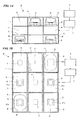
- the vehicle storage rack 1 contains a plurality of vehicle spaces (a total of twenty-seven spaces) arranged in three rows in the back-and-forth direction, in three columns in the right-and-left direction, and in three levels in the up-and-down direction.
- One space of the spaces is set as an entrance area E (e.g., the space positioned at upper-right in FIG. 1B ).
- Another space adjacent to the entrance area E is set as a positional adjustment area H.
- the other twenty-five spaces are set as storage spaces S.
- the entrance area E is a space provided with an entrance gate to the automated parking facility at which the vehicle M moving from the entrance gate stops.
- the positional adjustment area H is a space which is arranged to be adjacent to the entrance area E and is for performing positional adjustment (support portion positional adjustment) of the vehicle M which has moved into the automated parking facility and has been mounted on the pallet 2.
- the storage spaces S are spaces in which the vehicle M conveyed by the pallet 2 is stored.
- the pallets 2 are stored in parts of these spaces.
- the total number of the pallets 2 is set to be less than the total number of the vehicle spaces of the vehicle storage rack 1 in order that the pallets 2 are movable inside the automated parking facility P.
- the number of the spaces in the vehicle storage rack 1 is assumed to be twenty-seven for convenience of description, but the number of spaces may be greater than or less than twenty-seven, and the arrangement of spaces (the shape of the vehicle storage rack 1) may be a shape other than a cuboid.
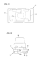
- the pallet 2 includes a vehicle support member 21 (vehicle support portion) on which the vehicle is mounted, and a restriction member 22 (movable portion) arranged under the vehicle support member 21.
- the vehicle support member 21 is a rectangular metal plate and is formed to be smaller than each space (each of the entrance area E, the positional adjustment area H and the storage spaces S) of the vehicle storage rack 1 in size. As described below, even when the relative position of the vehicle support member 21 to the restriction member 22 is moved to be maximum using the adjustment device (the ball screw unit 3 and the motor 4), the vehicle support member 21 can be kept to be inside each space because the vehicle support member 21 is formed to be smaller than each space in size.
- An opening 21a (magnetic flux transparent (transmissive) portion) is formed in the central region of the vehicle support member 21. As shown in FIGS. 2A through 2C , the opening 21a is provided in a position facing a power-receiving coil J provided on the bottom of the vehicle M, and is formed to be larger than the power-receiving coil J in size in the horizontal direction.
- the opening 21 a is provided in the vehicle support member 21 mainly in order not to block the magnetic field emitted from the power-transmitting coil 6. Even if the vehicle M is mounted on the pallet 2 with a positional misalignment, the magnetic field can always pass through the opening 21 a, and the wireless power transmission to the power-receiving coil J can be efficiently performed, because the opening 21a is formed to be larger than the power-receiving coil J in size.
- the opening 21a may be filled with a magnetic field transparent material such as a resin which does not block the magnetic field, for example, in order to increase the mechanical strength of the vehicle support member 21.
- a side of the pair of short edges of the vehicle support member 21 is provided with a female screw portion 31 (described below) of the ball screw unit 3 along each short edge.
- the restriction member 22 is a rectangular metal plate having a size which can be accommodated in each space (each of the entrance area E, the positional adjustment area H and the storage spaces S) of the vehicle storage rack 1, and is disposed being overlapped with the vehicle support member 21 under the vehicle support member 21.
- An opening 22a (magnetic flux transparent portion) is formed in the central region of the restriction member 22.
- the opening 22a is provided in a position facing the power-transmitting coil 6 provided on a floor s1 of the storage space S when the restriction member 22 is positioned inside the storage space S.
- the opening 22a is formed to be slightly larger than the power-transmitting coil 6 in size in the horizontal direction.
- a portion of the restriction member 22 facing the power-transmitting coil 6 has the magnetic field transmissibility. Since the opening 22a is formed to be slightly larger than the power-transmitting coil 6 in size, the magnetic field emitted by the power-transmitting coil 6 can pass through the opening 22a without being blocked by the restriction member 22 during the wireless power transmission, and the power supplying can be efficiently performed.
- the restriction member 22 in this embodiment supports the vehicle support member 21 from the lower side thereof.
- the present invention is not limited to this configuration, and the restriction member 22 may support the vehicle support member 21 from the upper side or from a lateral side thereof without interfering move of the vehicle M (during moving into or out of the automated parking facility).
- the restriction member 22 together with the vehicle support member 21 can move to a position facing the power-transmitting coil 6 in the storage space S.
- the opening 22a is provided in the restriction member 22 mainly in order not to block the magnetic field emitted from the power-transmitting coil 6.
- the opening 22a may be filled with a magnetic field transparent material such as a resin which does not block the magnetic field in order to increase the mechanical strength of the restriction member 22, similarly to the vehicle support member 21.
- a male screw portion 32 (described below) of the ball screw unit 3 is rotatably attached to a side of the pair of short edges of the restriction member 22 along each short edge via a bearing or the like (not shown). In FIGS. 2B and 2C , a structure used for attaching the male screw portion 32 to the restriction member 22 is omitted.
- the vehicle support member 21 and the restriction member 22 are connected to each other by screwing the male screw portion 32 to the female screw portion 31 of the ball screw unit 3.
- the vehicle support member 21 and the restriction member 22 move backward and forward in the horizontal direction, rightward and leftward in the horizontal direction, and upward and downward, driven by a pallet conveyance device (not shown) controlled by the control device 7, and stop at one of the spaces (the entrance area E, the positional adjustment area H and the storage spaces S) of the vehicle storage rack 1.
- the pallet conveyance device is connected only to the restriction member 22.
- the restriction member 22 is stopped (located) at a predetermined position above the power-transmitting coil 6 by contacting a wall or the like (a locating portion) of the storage space S.
- the pallet 2 is stopped (located) at a predetermined position inside each area by contacting a wall or the like (a locating portion) of each area.
- the locating portion of the storage space S or the like is not limited to the wall or the like, and may be a stopper or the like provided in the storage space S or the like.
- the locating of the restriction member 22 may be performed using a sensor such as a light sensor or a magnetic sensor.
- a sensor such as a light sensor or a magnetic sensor.
- a light emitter which emits light, or a reflector (a mirror, a silver-colored tape or the like) which reflects the light emitted from the light sensor back into the light sensor may be used together as a sensing target.
- a magnet or the like may be used together as a sensing target.
- the above sensor is provided in either the restriction member 22 or each space, namely, the storage spaces S, the entrance area E and the positional adjustment area H.
- the sensing target is provided in the other of the restriction member 22 and each space, namely, the storage spaces S, the entrance area E and the positional adjustment area H.
- a strip-shaped reflector is fixed on the surface of the restriction member 22, and a light sensor is arranged in the storage space S so as to have a positional relationship with the reflector, in which the light emitted from the light emitter is reflected by the reflector and is incident on the light sensor only when the restriction member 22 is located at a predetermined position in the area, and the light reflected by the reflector is not incident on the light sensor when the restriction member 22 is located at the other positions.
- the restriction member 22 can stop (be located) at a predetermined position above the power-transmitting coil 6 without contacting the wall or the like of the storage space S during the movement of the restriction member 22 to the storage space S.
- the ball screw unit 3 includes a screw having an appropriately narrow pitch.
- the rotation of the male screw portion 32 can be prevented even if a force is added to the ball screw unit 3 in the axial direction of the ball screw unit 3 (in the direction along the short edge of the pallet 2 in this embodiment).
- the vehicle M is mounted on the vehicle support member 21 as shown in the drawings.
- the vehicle M being a target to which the automated parking facility P supplies electric power, includes a hybrid vehicle driven by a combustion engine and by an electric motor, or an electric vehicle driven by an electric motor. That is, the target of power supply is a vehicle in which electric power that the power-receiving coil J wirelessly receives from the power-transmitting coil 6 is stored in a battery, and electric power stored in the battery feeds the driving electric motor. In contrast, the target of power supply does not cover a normal vehicle R not including a power-receiving circuit, a battery and the like, and driven only by a combustion engine.
- the power-receiving coil J is a helical coil having a predetermined coil diameter and is provided on the bottom of the vehicle M so that the coil axis is in the vertical direction. Both ends of the power-receiving coil J are connected to input terminals of a power-receiving circuit (not shown), and the power-receiving coil J is electromagnetically coupled to the power-transmitting coil 6 (described below) and wirelessly receives AC power.
- the power-receiving circuit includes a resonance capacitor, and the resonance capacitor together with the power-receiving coil J composes a power-receiving-side resonance circuit.
- the power-receiving circuit is a rectifier circuit which converts the AC power from the power-receiving coil J into DC power and which supplies the DC power to the battery.
- the capacitance of the resonance capacitor of the power-receiving circuit is set so that the resonance frequency of a power-supplying-side resonance circuit (described below) and the resonance frequency of the power-receiving-side resonance circuit are the same frequency.
- the ball screw unit 3 includes the female screw portion 31 and the bar-shaped male screw portion 32.
- Female screw grooves are formed in the female screw portion 31, and male screw grooves screwed to the female screw portion 31 are formed on the circumferential surface of the male screw portion 32.
- the female screw portion 31 is fixed to a side of the pair of short edges of the vehicle support member 21 along each short edge.
- the male screw portion 32 is rotatably provided on a side of the pair of short edges of the restriction member 22 via a bearing or the like (not shown) along each short edge.
- the male screw portion 32 is connected to the motor 4 via gears or the like (not shown), and rotates being driven by the motor 4. Since the female screw portion 31 fixed to the vehicle support member 21 cannot rotate, the vehicle support member 21, to which the female screw portion 31 is fixed, moves in the width direction thereof (the horizontal direction) with respect to the restriction member 22 in accordance with the rotation of the male screw portion 32. That is, the ball screw unit 3 adjusts the relative positional relationship between the vehicle support member 21 and the restriction member 22 in the width direction.
- the end surface of the male screw portion 32 and the end surface of a shaft face each other, and the both end surfaces are planar and formed of a material having a large friction coefficient, wherein the shaft is driven by the motor 4 via gears or the like (not shown).
- the end surface of the male screw portion 32 is pushed against the end surface of the shaft, and thereby the male screw portion 32 can be connected to the motor 4. Accordingly, the male screw portion 32 can rotate in synchronization with the rotation of the motor 4.
- the motor 4 is provided in the positional adjustment area H.
- the motor 4 is connected to the male screw portion 32 via gears or the like (not shown), and rotates based on motor drive signals input from the control device 7, thereby rotating the male screw portion 32.
- the rotary shaft of the motor 4 may be directly connected to the male screw portion 32 without gears or the like.
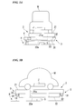
- the power-receiving coil detector 5 is provided in the positional adjustment area H (e.g., on a floor h1 thereof), and detects the position of the power-receiving coil J of the vehicle M mounted on the pallet 2.
- the power-receiving coil detector 5 is an imager which images the power-receiving coil J having a mark or the like which is provided in a predetermined position thereof, or is a light sensor which detects light of a light emitter such as an LED (light emitting diode) provided on the power-receiving coil J.
- the power-receiving coil detector 5 outputs, to the control device 7, detection data (detection result) showing the detection result of taken images or of light, or the like.
- the control device 7 determines the position (position in the horizontal direction) of the power-receiving coil J of the vehicle M on the pallet 2 based on the detection data input from the power-receiving coil detector 5. It is to be noted that the mark or the like may be provided in a position different from that of the power-receiving coil J (for example, in the vicinity of the power-receiving coil J of the vehicle M). In this case, the position of the power-receiving coil J is calculated using the detected position of the mark or the like.
- the power-transmitting coil 6 is a helical coil having a predetermined coil diameter.
- the power-transmitting coil 6 is provided on the floor s1 of the storage space S so as to have an attitude in which the coil axis of the power-transmitting coil 6 is in the up-and-down direction (the vertical direction) and so as to face the opening 22a of the restriction member 22 which has been conveyed into the storage space S.
- the power-transmitting coil 6 is arranged on the floor s1, and may be exposed or may be covered by a non-magnetic material such as plastic.
- the power-transmitting coil 6 has approximately the same coil diameter as that of the power-receiving coil J, and both ends of the power-transmitting coil 6 are connected to output terminals of a power-supplying circuit (not shown). High frequency AC power is supplied from the power-supplying circuit to the power-transmitting coil 6, and thereby the power-transmitting coil 6 generates a magnetic field.
- the vehicle M can be wirelessly supplied with electric power through the magnetic field.
- the power-supplying circuit includes a resonance capacitor and the resonance capacitor together with the power-transmitting coil 6 composes the power-supplying-side resonance circuit.
- the power-supplying circuit is an inverter which converts the input DC power into AC power (high frequency AC power) and which supplies the AC power to the power-transmitting coil 6.
- the control device 7 controls the entire automated parking facility P.
- the control device 7 is electrically connected to various objects to be controlled which include the power-supplying circuit (not shown) and to the operation device 8.
- the control device 7 comprehensively controls the various objects to be controlled based on, for example, control programs stored in non-volatile storages provided therein, and on operating instruction information input from the operation device 8.
- the operation device 8 is an input device into which a manager, who manages and operates the automated parking facility P, manually inputs operating instructions, and is, for example, an operation panel including hardware keys, or is a touch panel.
- the operating instructions manually input into the operation device 8 through the operation of the manager are sent as the operating instruction information, from the operation device 8 to the control device 7.
- the operation device 8 is provided with, for example, a manual operation button (storage instruction button) in order to instruct the automated parking facility to store the vehicle M positioned at the entrance area E.
- the control device 7 starts movement of the pallet 2 (the restriction member 22) in the entrance area E on which the vehicle M is mounted.
- control device 7 moves the pallet 2 to the positional adjustment area H, before moving the pallet 2 to the entrance area E (refer to FIG. 5A ).
- the control device 7 makes the motor 4 rotate the male screw portion 32 after the motor 4 and the male screw portion 32 are connected to each other, thereby returning the relative positional relationship in the width direction between the vehicle support member 21 and the restriction member 22 to the original state thereof (a state having no positional misalignment therebetween, for example, the center positions of the vehicle support member 21 and of the restriction member 22 in the width direction are the same in the horizontal direction) (refer to FIG. 5B ). It is to be noted that this step may be performed in an area other than the positional adjustment area H in a case where a drive device is provided in the pallet 2 in order to perform the relative positional adjustment between the vehicle support member 21 and the restriction member 22.
- control device 7 moves the pallet 2 to the entrance area E (refer to FIG. 5C ).
- the vehicle M In order to store the vehicle M in the automated parking facility P, for example, the vehicle M is operated by a driver thereof, and thereby is mounted on the pallet 2 in the entrance area E provided with the entrance gate (refer to FIG. 5D ).
- the manager presses the storage instruction button of the operation device 8 of the automated parking facility P, thereby outputting storage instructions to the control device 7.
- the manager presses a charging instruction button in addition to the storage instruction button, thereby outputting charging instructions to the control device 7.
- the control device 7 of the automated parking facility P moves, from the entrance area E to the positional adjustment area H, the pallet 2 on which the vehicle M is mounted (refer to FIG. 5E ). Subsequently, the control device 7 determines the position of the power-receiving coil J of the vehicle M on the pallet 2 based on the detection data input from the power-receiving coil detector 5 provided in the positional adjustment area H. The control device 7 makes the motor 4 rotate the male screw portion 32 based on the detection result by the power-receiving coil detector 5, that is, the positional information of the power-receiving coil J.
- the vehicle support member 21 with the vehicle M being mounted thereon moves in the width direction (the horizontal direction) with respect to the restriction member 22, and the position of the vehicle M is adjusted so that the power-receiving coil J faces the power-transmitting coil 6 in the storage space S (refer to FIG. 5F , support portion positional adjustment). That is, the positional misalignment between the power-receiving coil J and the power-transmitting coil 6 in the width direction of the pallet 2 is decreased.
- the control device 7 It is sufficient to perform the positional adjustment of the vehicle support member 21 with respect to the restriction member 22 using the control device 7 so that the power-receiving coil J and the power-transmitting coil 6 have a positional relationship suitable for the wireless power transmission when the vehicle M is conveyed to the storage space S.
- the control of the control device 7 is performed so that the positional misalignment in the horizontal direction between the power-receiving coil J and the power-transmitting coil 6 is less than a predetermined threshold value. This threshold value is determined based on the power transmission efficiency or the like in the wireless power transmission.
- the control device 7 moves, to the storage space S, the pallet 2 on which the vehicle M is mounted (refer to FIG. 5G ).
- the vehicle M is mounted on the pallet 2 in the entrance area E with deviation to the left in FIG. 5D with respect to the vehicle support member 21 and the restriction member 22.
- the vehicle M is positioned right above the restriction member 22 in FIG. 5F .
- the pallet 2 on which the vehicle M is mounted moves to the storage space S, and the restriction member 22 stops at the position right above the power-transmitting coil 6.
- the vehicle M is also located right above the power-transmitting coil 6. Therefore, the power-receiving coil J is arranged at the position right above the power-transmitting coil 6, that is, at the position in which the wireless power transmission is most efficient (refer to FIG. 5G ).
- the power-transmitting coil 6 and the power-receiving coil J are located at the centers (centers in the horizontal direction) of the storage space S and of the vehicle M, respectively.
- the power-transmitting coil 6 and the power-receiving coil J can be arranged so as to face each other, they may be provided in locations other than the centers.
- the restriction member 22 stops at the location right above the power-transmitting coil 6.
- the restriction member 22 may stop at a location other than the location right above the power-transmitting coil 6.
- the control device 7 of the automated parking facility P When the movement of the vehicle M to the storage space S is finished, the control device 7 of the automated parking facility P outputs control instructions to the power-supplying circuit, and starts supplying AC power to the power-transmitting coil 6.
- the vehicle M controls the power-receiving circuit while monitoring the charged state of the battery, and properly charges the battery. As a result of this charging process, when the charge of the battery is completed, the vehicle M outputs charging completion signals which indicate this state, through a wireless communication unit or the like (not shown).
- the control device 7 of the automated parking facility P receives the charging completion signals through another wireless communication unit or the like (not shown), the control device 7 outputs control signals to the power-supplying circuit, thereby completing supplying electric power to the power-transmitting coil 6.
- the wireless power transmission to the vehicle M is performed, the attachment and removal of a power-supplying cable to and from the vehicle M is unnecessary for the power supplying.
- the increase of the wiring of the pallet 2 due to the arrangement of a power-supplying cable on the pallet 2 can be prevented.
- the relative positional relationship between the vehicle support member 21 and the restriction member 22 in the width direction can be adjusted, and the position of the vehicle support member 21 disposed above the power-transmitting coil 6 is adjusted so that the power-receiving coil J of the vehicle M and the power-transmitting coil 6 of the storage space S face each other.
- the efficient wireless power transmission can be performed through the above adjustment, even if the vehicle M stops on the vehicle support member 21 with a positional misalignment at the time of entering the automated parking facility.
- the relative positional relationship between the vehicle support member 21 and the restriction member 22 in the width direction is returned to the original state thereof each time before the pallet 2 is moved to the entrance area E, and thereby, the positional misalignment between the vehicle support member 21 and the restriction member 22 can be prevented from significantly increasing.
Landscapes
- Engineering & Computer Science (AREA)
- Architecture (AREA)
- Power Engineering (AREA)
- Mechanical Engineering (AREA)
- Transportation (AREA)
- Civil Engineering (AREA)
- Structural Engineering (AREA)
- Computer Networks & Wireless Communication (AREA)
- Charge And Discharge Circuits For Batteries Or The Like (AREA)
- Electric Propulsion And Braking For Vehicles (AREA)
- Secondary Cells (AREA)
Abstract
Description
- The present invention relates to an automated parking facility.
- Priority is claimed on Japanese Patent Application No.
2012-185729, filed August 24, 2012 - In recent years, the use of vehicles equipped with an electric motor as a drive source instead of a combustion engine or together with the engine has increased in order to realize a low-carbon society. An electric vehicle (EV) is an example of a vehicle equipped with an electric motor instead of a combustion engine, and a hybrid vehicle (HV) is an example of a vehicle equipped with an electric motor together with a combustion engine. Such a vehicle includes a rechargeable battery (e.g., a secondary battery such as a lithium-ion battery or a nickel-hydrogen battery) which supplies electric power used for driving the electric motor thereto, and is configured to charge the battery using electric power supplied from an external power unit.
- Most electric vehicles and hybrid vehicles (to be precise, plug-in hybrid vehicles) currently in practical use receive electric power used for charging the battery via a power-supplying cable which is attachable and removable for connecting the power unit and the vehicle. For example,
Patent Document 1 discloses a technology in which electric power is transmitted via a power-supplying cable which is attachable and removable for connecting to a vehicle, in an automated parking facility which stores the vehicle in a storage space using a movable pallet. In contrast to such a technology, nowadays, as shown inPatent Document 2, a method is proposed in which a vehicle is supplied with electric power for charging a battery using a technology in which electric power is wirelessly from a power-transmitting coil to a power-receiving coil. -
- [Patent Document 1] Japanese Unexamined Patent Application, First Publication No.
H5-256038 - [Patent Document 2] Japanese Unexamined Patent Application, First Publication No.
2009-225551 - In the technology disclosed in
Patent Document 1, since the attachment and removal of the power-supplying cable is necessary in order to supply electric power to the vehicle, the attachment and removal operations of the power-supplying cable are realized by a complex automatic apparatus or relying on human-intervention during the power supplying. Additionally, in the technology disclosed inPatent Document 1, since it is necessary to provide the power-supplying cable in the pallet, the wiring in the pallet is increased, and the installation and maintenance of the automated parking facility may require much time and effort. In the technology disclosed inPatent Document 2, if the relative positional relationship between the power-transmitting coil and the power-receiving coil deviates from the appropriate range, efficient transmission of electric power is difficult. Therefore, in a case where the technology ofPatent Document 2 is applied to an automated parking facility, the wireless power transmission may not be efficiently performed due to variations in stop position of a vehicle on the pallet at the time of storing the vehicle. - The present invention is made in view of the above circumstances, and provides an automated parking facility having the following features:
- (1) The attachment and removal of a power-supplying cable to and from a vehicle is unnecessary during the power supplying.
- (2) The increase of the wiring in a pallet can be prevented.
- (3) The wireless power transmission can be efficiently performed even if variations in the stop position of a vehicle occur at the time of storing the vehicle.
- According to a first aspect of the present invention, an automated parking facility conveying a vehicle to a storage space and storing the vehicle in the storage space, the automated parking facility includes: a power-transmitting coil provided on a floor of the storage space, and performing wireless power transmission to a power-receiving coil provided on a bottom of the vehicle; a vehicle support portion allowing the vehicle to be mounted on the vehicle support portion; a movable portion supporting the vehicle support portion, configured to move together with the vehicle support portion to a position facing the power-transmitting coil in the storage space, and configured to stop at a position above the power-transmitting coil in the storage space; an adjustment device configured to adjust a position of the vehicle support portion in a horizontal direction with respect to the movable portion; and a controller controlling the adjustment device, and performing support portion positional adjustment in which the position of the vehicle support portion is adjusted with respect to the movable portion so that the power-receiving coil and the power-transmitting coil have a positional relationship suitable for the wireless power transmission.
- According to a second aspect of the present invention, in the first aspect, the automated parking facility further includes a positional adjustment area allowing the movable portion together with the vehicle support portion to move to the positional adjustment area. The adjustment device is provided in the positional adjustment area. In addition, the controller performs the support portion positional adjustment when the movable portion and the vehicle support portion with the vehicle being mounted are located at the positional adjustment area, before the movable portion and the vehicle support portion move to the storage space.
- According to a third aspect of the present invention, in the second aspect, the positional adjustment area is provided with a power-receiving coil detector detecting a position of the power-receiving coil. In addition, the controller performs the support portion positional adjustment based on a detection result of the power-receiving coil detector.
- According to a fourth aspect of the present invention, in the second aspect, the controller returns the position of the vehicle support portion in the horizontal direction with respect to the movable portion to an original state by controlling the adjustment device, when the movable portion and the vehicle support portion are located at the positional adjustment area, before the vehicle is mounted on the vehicle support portion.
- According to a fifth aspect of the present invention, in the second aspect, a second power-transmitting coil is provided on a floor of the positional adjustment area in order to perform wireless power transmission to the power-receiving coil. In addition, the controller performs the support portion positional adjustment based on a power-transmitting efficiency of the wireless power transmission between the power-receiving coil and the second power-transmitting coil when the movable portion and the vehicle support portion with the vehicle being mounted are located at the positional adjustment area.
- According to a sixth aspect of the present invention, in the first aspect, the controller returns the position of the vehicle support portion in the horizontal direction with respect to the movable portion to an original state by controlling the adjustment device, before the vehicle is mounted on the vehicle support portion and the movable portion.
- According to a seventh aspect of the present invention, in the first aspect, the controller performs the support portion positional adjustment based on a power-transmitting efficiency of the wireless power transmission between the power-receiving coil and the power-transmitting coil, when the movable portion and the vehicle support portion with the vehicle being mounted are located at the storage space.
- According to an eighth aspect of the present invention, in the first aspect, the adjustment device includes a screw unit including a female screw portion and a male screw portion screwed to the female screw portion; and a drive device driving the screw unit. In addition, the female screw portion is provided in one of the vehicle support portion and the movable portion, and the male screw portion is rotatably provided in the other of the vehicle support portion and the movable portion.
- According to a ninth aspect of the present invention, in the first aspect, each of the vehicle support portion and the movable portion includes a magnetic flux transparent portion allowing magnetic flux to penetrate through the magnetic flux transparent portion, wherein the magnetic flux is between the power-receiving coil and the power-transmitting coil during the wireless power transmission.
- According to a tenth aspect of the present invention, in the ninth aspect, size in the horizontal direction of the magnetic flux transparent portion of the vehicle support portion is set to be greater than size in the horizontal direction of the power-receiving coil.
- According to the present invention, since electric power is wirelessly supplied to a vehicle, attachment and removal of a power-supplying cable to and from the vehicle is unnecessary for the power supplying. According to the present invention, the increase of the wiring of the pallet due to the arrangement of a power-supplying cable on the pallet can be prevented. In addition, according to the present invention, the relative positional relationship between the vehicle support portion and the movable portion in the horizontal direction can be adjusted, and the position of the vehicle support portion disposed above the power-transmitting coil can be adjusted so that the power-receiving coil of the vehicle and the power-transmitting coil of the storage space face each other. Therefore, the wireless power transmission can be efficiently performed even if the vehicle stops on the vehicle support portion with a positional misalignment at the time of entering the automated parking facility.
-
-
FIG. 1A is a front view of an automated parking facility of an embodiment of the present invention. -
FIG. 1B is a top view of the automated parking facility. -
FIG. 2A is a plan view of a pallet of the embodiment of the present invention. -
FIG. 2B is a front view of the pallet and a ball screw unit of the embodiment of the present invention. -
FIG. 2C is a side view of the pallet and the ball screw unit. -
FIG. 3A is a front view showing a positional adjustment area of the embodiment of the present invention. -
FIG. 3B is a side view showing the positional adjustment area. -
FIG. 4A is a front view showing a storage space of the embodiment of the present invention. -
FIG. 4B is a side view of the storage space. -
FIG. 5A is a schematic view showing a first step of the operation of the automated parking facility. -
FIG. 5B is a schematic view showing a second step of the operation of the automated parking facility. -
FIG. 5C is a schematic view showing a third step of the operation of the automated parking facility. -
FIG. 5D is a schematic view showing a fourth step of the operation of the automated parking facility. -
FIG. 5E is a schematic view showing a fifth step of the operation of the automated parking facility. -
FIG. 5F is a schematic view showing a sixth step of the operation of the automated parking facility. -
FIG. 5G is a schematic view showing a seventh step of the operation of the automated parking facility. - Hereinafter, an embodiment of the present invention is described with reference to the drawings.
- As shown in
FIGS. 1A through 4B , an automated parking facility P of this embodiment includes avehicle storage rack 1, apallet 2, a ball screw unit 3 (a screw unit, an adjustment device), a motor 4 (a drive device, an adjustment device), a power-receivingcoil detector 5, a power-transmittingcoil 6, a control device 7 (a controller), and anoperation device 8. The automated parking facility P conveys a vehicle M to a storage space S and stores the vehicle M in the storage space S. Themotor 4 corresponds to a drive device of the present invention. Theball screw unit 3 and themotor 4 correspond to an adjustment device of the present invention. - As shown in
FIGS. 1A and 1B , thevehicle storage rack 1 contains a plurality of vehicle spaces (a total of twenty-seven spaces) arranged in three rows in the back-and-forth direction, in three columns in the right-and-left direction, and in three levels in the up-and-down direction. One space of the spaces is set as an entrance area E (e.g., the space positioned at upper-right inFIG. 1B ). Another space adjacent to the entrance area E is set as a positional adjustment area H. The other twenty-five spaces are set as storage spaces S. The entrance area E is a space provided with an entrance gate to the automated parking facility at which the vehicle M moving from the entrance gate stops. - The positional adjustment area H is a space which is arranged to be adjacent to the entrance area E and is for performing positional adjustment (support portion positional adjustment) of the vehicle M which has moved into the automated parking facility and has been mounted on the
pallet 2. The storage spaces S are spaces in which the vehicle M conveyed by thepallet 2 is stored. Thepallets 2 are stored in parts of these spaces. The total number of thepallets 2 is set to be less than the total number of the vehicle spaces of thevehicle storage rack 1 in order that thepallets 2 are movable inside the automated parking facility P. The number of the spaces in thevehicle storage rack 1 is assumed to be twenty-seven for convenience of description, but the number of spaces may be greater than or less than twenty-seven, and the arrangement of spaces (the shape of the vehicle storage rack 1) may be a shape other than a cuboid. - The
pallet 2 includes a vehicle support member 21 (vehicle support portion) on which the vehicle is mounted, and a restriction member 22 (movable portion) arranged under thevehicle support member 21. Thevehicle support member 21 is a rectangular metal plate and is formed to be smaller than each space (each of the entrance area E, the positional adjustment area H and the storage spaces S) of thevehicle storage rack 1 in size. As described below, even when the relative position of thevehicle support member 21 to therestriction member 22 is moved to be maximum using the adjustment device (theball screw unit 3 and the motor 4), thevehicle support member 21 can be kept to be inside each space because thevehicle support member 21 is formed to be smaller than each space in size. Anopening 21a (magnetic flux transparent (transmissive) portion) is formed in the central region of thevehicle support member 21. As shown inFIGS. 2A through 2C , theopening 21a is provided in a position facing a power-receiving coil J provided on the bottom of the vehicle M, and is formed to be larger than the power-receiving coil J in size in the horizontal direction. - The opening 21 a is provided in the
vehicle support member 21 mainly in order not to block the magnetic field emitted from the power-transmittingcoil 6. Even if the vehicle M is mounted on thepallet 2 with a positional misalignment, the magnetic field can always pass through the opening 21 a, and the wireless power transmission to the power-receiving coil J can be efficiently performed, because theopening 21a is formed to be larger than the power-receiving coil J in size. In thevehicle support member 21, theopening 21a may be filled with a magnetic field transparent material such as a resin which does not block the magnetic field, for example, in order to increase the mechanical strength of thevehicle support member 21. A side of the pair of short edges of thevehicle support member 21 is provided with a female screw portion 31 (described below) of theball screw unit 3 along each short edge. - The
restriction member 22 is a rectangular metal plate having a size which can be accommodated in each space (each of the entrance area E, the positional adjustment area H and the storage spaces S) of thevehicle storage rack 1, and is disposed being overlapped with thevehicle support member 21 under thevehicle support member 21. Anopening 22a (magnetic flux transparent portion) is formed in the central region of therestriction member 22. Theopening 22a is provided in a position facing the power-transmittingcoil 6 provided on a floor s1 of the storage space S when therestriction member 22 is positioned inside the storage space S. Theopening 22a is formed to be slightly larger than the power-transmittingcoil 6 in size in the horizontal direction. That is, a portion of therestriction member 22 facing the power-transmittingcoil 6 has the magnetic field transmissibility. Since theopening 22a is formed to be slightly larger than the power-transmittingcoil 6 in size, the magnetic field emitted by the power-transmittingcoil 6 can pass through theopening 22a without being blocked by therestriction member 22 during the wireless power transmission, and the power supplying can be efficiently performed. - The
restriction member 22 in this embodiment supports thevehicle support member 21 from the lower side thereof. However, the present invention is not limited to this configuration, and therestriction member 22 may support thevehicle support member 21 from the upper side or from a lateral side thereof without interfering move of the vehicle M (during moving into or out of the automated parking facility). Therestriction member 22 together with thevehicle support member 21 can move to a position facing the power-transmittingcoil 6 in the storage space S. - The
opening 22a is provided in therestriction member 22 mainly in order not to block the magnetic field emitted from the power-transmittingcoil 6. In therestriction member 22, theopening 22a may be filled with a magnetic field transparent material such as a resin which does not block the magnetic field in order to increase the mechanical strength of therestriction member 22, similarly to thevehicle support member 21. A male screw portion 32 (described below) of theball screw unit 3 is rotatably attached to a side of the pair of short edges of therestriction member 22 along each short edge via a bearing or the like (not shown). InFIGS. 2B and2C , a structure used for attaching themale screw portion 32 to therestriction member 22 is omitted. - The
vehicle support member 21 and therestriction member 22 are connected to each other by screwing themale screw portion 32 to thefemale screw portion 31 of theball screw unit 3. Thevehicle support member 21 and therestriction member 22 move backward and forward in the horizontal direction, rightward and leftward in the horizontal direction, and upward and downward, driven by a pallet conveyance device (not shown) controlled by thecontrol device 7, and stop at one of the spaces (the entrance area E, the positional adjustment area H and the storage spaces S) of thevehicle storage rack 1. In general, the pallet conveyance device is connected only to therestriction member 22. During the movement of therestriction member 22 to the storage space S, therestriction member 22 is stopped (located) at a predetermined position above the power-transmittingcoil 6 by contacting a wall or the like (a locating portion) of the storage space S. During the movement of therestriction member 22 to the entrance area E or to the positional adjustment area H, the pallet 2 (the restriction member 22) is stopped (located) at a predetermined position inside each area by contacting a wall or the like (a locating portion) of each area. The locating portion of the storage space S or the like is not limited to the wall or the like, and may be a stopper or the like provided in the storage space S or the like. The locating of therestriction member 22 may be performed using a sensor such as a light sensor or a magnetic sensor. In a case where the light sensor is employed, a light emitter which emits light, or a reflector (a mirror, a silver-colored tape or the like) which reflects the light emitted from the light sensor back into the light sensor may be used together as a sensing target. In a case where the magnetic sensor is employed, a magnet or the like may be used together as a sensing target. The above sensor is provided in either therestriction member 22 or each space, namely, the storage spaces S, the entrance area E and the positional adjustment area H. The sensing target is provided in the other of therestriction member 22 and each space, namely, the storage spaces S, the entrance area E and the positional adjustment area H. - In an example of employing a light sensor, a strip-shaped reflector is fixed on the surface of the
restriction member 22, and a light sensor is arranged in the storage space S so as to have a positional relationship with the reflector, in which the light emitted from the light emitter is reflected by the reflector and is incident on the light sensor only when therestriction member 22 is located at a predetermined position in the area, and the light reflected by the reflector is not incident on the light sensor when therestriction member 22 is located at the other positions. When the automated parking facility is configured so that the pallet conveyance device operates while the light sensor does not detect the light and so that the pallet conveyance device stops operating if the light sensor detects the light, therestriction member 22 can stop (be located) at a predetermined position above the power-transmittingcoil 6 without contacting the wall or the like of the storage space S during the movement of therestriction member 22 to the storage space S. - It is preferable that the
ball screw unit 3 includes a screw having an appropriately narrow pitch. In this configuration, when thepallet 2 moves backward and forward in the horizontal direction, rightward and leftward in the horizontal direction, and upward and downward, the rotation of themale screw portion 32 can be prevented even if a force is added to theball screw unit 3 in the axial direction of the ball screw unit 3 (in the direction along the short edge of thepallet 2 in this embodiment). Thus, it is possible to prevent the relative position between thevehicle support member 21 and therestriction member 22 from unexpectedly changing at the time other than the positional adjustment at the positional adjustment area H or the like. - The vehicle M is mounted on the
vehicle support member 21 as shown in the drawings. The vehicle M, being a target to which the automated parking facility P supplies electric power, includes a hybrid vehicle driven by a combustion engine and by an electric motor, or an electric vehicle driven by an electric motor. That is, the target of power supply is a vehicle in which electric power that the power-receiving coil J wirelessly receives from the power-transmittingcoil 6 is stored in a battery, and electric power stored in the battery feeds the driving electric motor. In contrast, the target of power supply does not cover a normal vehicle R not including a power-receiving circuit, a battery and the like, and driven only by a combustion engine. - The power-receiving coil J is a helical coil having a predetermined coil diameter and is provided on the bottom of the vehicle M so that the coil axis is in the vertical direction. Both ends of the power-receiving coil J are connected to input terminals of a power-receiving circuit (not shown), and the power-receiving coil J is electromagnetically coupled to the power-transmitting coil 6 (described below) and wirelessly receives AC power. The power-receiving circuit includes a resonance capacitor, and the resonance capacitor together with the power-receiving coil J composes a power-receiving-side resonance circuit. The power-receiving circuit is a rectifier circuit which converts the AC power from the power-receiving coil J into DC power and which supplies the DC power to the battery. The capacitance of the resonance capacitor of the power-receiving circuit is set so that the resonance frequency of a power-supplying-side resonance circuit (described below) and the resonance frequency of the power-receiving-side resonance circuit are the same frequency.
- As shown in
FIGS. 2B and2C , theball screw unit 3 includes thefemale screw portion 31 and the bar-shapedmale screw portion 32. Female screw grooves are formed in thefemale screw portion 31, and male screw grooves screwed to thefemale screw portion 31 are formed on the circumferential surface of themale screw portion 32. Thefemale screw portion 31 is fixed to a side of the pair of short edges of thevehicle support member 21 along each short edge. Themale screw portion 32 is rotatably provided on a side of the pair of short edges of therestriction member 22 via a bearing or the like (not shown) along each short edge. - In the
ball screw unit 3, when thevehicle support member 21 and therestriction member 22 have moved to the positional adjustment area H, themale screw portion 32 is connected to themotor 4 via gears or the like (not shown), and rotates being driven by themotor 4. Since thefemale screw portion 31 fixed to thevehicle support member 21 cannot rotate, thevehicle support member 21, to which thefemale screw portion 31 is fixed, moves in the width direction thereof (the horizontal direction) with respect to therestriction member 22 in accordance with the rotation of themale screw portion 32. That is, theball screw unit 3 adjusts the relative positional relationship between thevehicle support member 21 and therestriction member 22 in the width direction. When thevehicle support member 21 and therestriction member 22 are located other than the positional adjustment area H, the connection between themale screw portion 32 and themotor 4 is released, and thus thepallet 2 can move without being held by themotor 4. Specifically, for example, the end surface of themale screw portion 32 and the end surface of a shaft face each other, and the both end surfaces are planar and formed of a material having a large friction coefficient, wherein the shaft is driven by themotor 4 via gears or the like (not shown). In this case, when thevehicle support member 21 and therestriction member 22 have moved to the positional adjustment area H, the end surface of themale screw portion 32 is pushed against the end surface of the shaft, and thereby themale screw portion 32 can be connected to themotor 4. Accordingly, themale screw portion 32 can rotate in synchronization with the rotation of themotor 4. - As shown in
FIG. 3A , themotor 4 is provided in the positional adjustment area H. Themotor 4 is connected to themale screw portion 32 via gears or the like (not shown), and rotates based on motor drive signals input from thecontrol device 7, thereby rotating themale screw portion 32. - In a case where the
ball screw unit 3 has a large speed reduction ratio and themotor 4 can generate large torque, the rotary shaft of themotor 4 may be directly connected to themale screw portion 32 without gears or the like. - As shown in
FIGS. 3A and 3B , the power-receivingcoil detector 5 is provided in the positional adjustment area H (e.g., on a floor h1 thereof), and detects the position of the power-receiving coil J of the vehicle M mounted on thepallet 2. For example, the power-receivingcoil detector 5 is an imager which images the power-receiving coil J having a mark or the like which is provided in a predetermined position thereof, or is a light sensor which detects light of a light emitter such as an LED (light emitting diode) provided on the power-receiving coil J. The power-receivingcoil detector 5 outputs, to thecontrol device 7, detection data (detection result) showing the detection result of taken images or of light, or the like. Thecontrol device 7 determines the position (position in the horizontal direction) of the power-receiving coil J of the vehicle M on thepallet 2 based on the detection data input from the power-receivingcoil detector 5. It is to be noted that the mark or the like may be provided in a position different from that of the power-receiving coil J (for example, in the vicinity of the power-receiving coil J of the vehicle M). In this case, the position of the power-receiving coil J is calculated using the detected position of the mark or the like. - The power-transmitting
coil 6 is a helical coil having a predetermined coil diameter. The power-transmittingcoil 6 is provided on the floor s1 of the storage space S so as to have an attitude in which the coil axis of the power-transmittingcoil 6 is in the up-and-down direction (the vertical direction) and so as to face theopening 22a of therestriction member 22 which has been conveyed into the storage space S. The power-transmittingcoil 6 is arranged on the floor s1, and may be exposed or may be covered by a non-magnetic material such as plastic. The power-transmittingcoil 6 has approximately the same coil diameter as that of the power-receiving coil J, and both ends of the power-transmittingcoil 6 are connected to output terminals of a power-supplying circuit (not shown). High frequency AC power is supplied from the power-supplying circuit to the power-transmittingcoil 6, and thereby the power-transmittingcoil 6 generates a magnetic field. The vehicle M can be wirelessly supplied with electric power through the magnetic field. The power-supplying circuit includes a resonance capacitor and the resonance capacitor together with the power-transmittingcoil 6 composes the power-supplying-side resonance circuit. The power-supplying circuit is an inverter which converts the input DC power into AC power (high frequency AC power) and which supplies the AC power to the power-transmittingcoil 6. - The
control device 7 controls the entire automated parking facility P. Thecontrol device 7 is electrically connected to various objects to be controlled which include the power-supplying circuit (not shown) and to theoperation device 8. Thecontrol device 7 comprehensively controls the various objects to be controlled based on, for example, control programs stored in non-volatile storages provided therein, and on operating instruction information input from theoperation device 8. - The
operation device 8 is an input device into which a manager, who manages and operates the automated parking facility P, manually inputs operating instructions, and is, for example, an operation panel including hardware keys, or is a touch panel. The operating instructions manually input into theoperation device 8 through the operation of the manager are sent as the operating instruction information, from theoperation device 8 to thecontrol device 7. Theoperation device 8 is provided with, for example, a manual operation button (storage instruction button) in order to instruct the automated parking facility to store the vehicle M positioned at the entrance area E. When the manual operation button is pressed, thecontrol device 7 starts movement of the pallet 2 (the restriction member 22) in the entrance area E on which the vehicle M is mounted. - Next, the operation of the automated parking facility P having the above configuration is described in detail with reference to
FIGS. 5A through 5G . - In the automated parking facility P, the
control device 7 moves thepallet 2 to the positional adjustment area H, before moving thepallet 2 to the entrance area E (refer toFIG. 5A ). - Next, the
control device 7 makes themotor 4 rotate themale screw portion 32 after themotor 4 and themale screw portion 32 are connected to each other, thereby returning the relative positional relationship in the width direction between thevehicle support member 21 and therestriction member 22 to the original state thereof (a state having no positional misalignment therebetween, for example, the center positions of thevehicle support member 21 and of therestriction member 22 in the width direction are the same in the horizontal direction) (refer toFIG. 5B ). It is to be noted that this step may be performed in an area other than the positional adjustment area H in a case where a drive device is provided in thepallet 2 in order to perform the relative positional adjustment between thevehicle support member 21 and therestriction member 22. - Thereafter, the
control device 7 moves thepallet 2 to the entrance area E (refer toFIG. 5C ). - In order to store the vehicle M in the automated parking facility P, for example, the vehicle M is operated by a driver thereof, and thereby is mounted on the
pallet 2 in the entrance area E provided with the entrance gate (refer toFIG. 5D ). The manager presses the storage instruction button of theoperation device 8 of the automated parking facility P, thereby outputting storage instructions to thecontrol device 7. At the time of storing the vehicle M, if the manager receives the charging request for the battery of the vehicle M from the driver, the manager presses a charging instruction button in addition to the storage instruction button, thereby outputting charging instructions to thecontrol device 7. - When the storage instructions and the charging instructions are input from the
operation device 8 into thecontrol device 7, thecontrol device 7 of the automated parking facility P moves, from the entrance area E to the positional adjustment area H, thepallet 2 on which the vehicle M is mounted (refer toFIG. 5E ). Subsequently, thecontrol device 7 determines the position of the power-receiving coil J of the vehicle M on thepallet 2 based on the detection data input from the power-receivingcoil detector 5 provided in the positional adjustment area H. Thecontrol device 7 makes themotor 4 rotate themale screw portion 32 based on the detection result by the power-receivingcoil detector 5, that is, the positional information of the power-receiving coil J. Accordingly, thevehicle support member 21 with the vehicle M being mounted thereon moves in the width direction (the horizontal direction) with respect to therestriction member 22, and the position of the vehicle M is adjusted so that the power-receiving coil J faces the power-transmittingcoil 6 in the storage space S (refer toFIG. 5F , support portion positional adjustment). That is, the positional misalignment between the power-receiving coil J and the power-transmittingcoil 6 in the width direction of thepallet 2 is decreased. It is sufficient to perform the positional adjustment of thevehicle support member 21 with respect to therestriction member 22 using thecontrol device 7 so that the power-receiving coil J and the power-transmittingcoil 6 have a positional relationship suitable for the wireless power transmission when the vehicle M is conveyed to the storage space S. For example, the control of thecontrol device 7 is performed so that the positional misalignment in the horizontal direction between the power-receiving coil J and the power-transmittingcoil 6 is less than a predetermined threshold value. This threshold value is determined based on the power transmission efficiency or the like in the wireless power transmission. - With respect to a positional misalignment between the power-receiving coil J and the power-transmitting
coil 6 in the length direction of thepallet 2, it is sufficient for the driver to stop the vehicle M within the range of the positional misalignment in which no performance degradation occurs in the wireless power transmission when the vehicle M is mounted on thepallet 2 in the entrance area E. After the positional adjustment of the vehicle M is finished, thecontrol device 7 moves, to the storage space S, thepallet 2 on which the vehicle M is mounted (refer toFIG. 5G ). - In the example shown in
FIGS. 5A through 5G , the vehicle M is mounted on thepallet 2 in the entrance area E with deviation to the left inFIG. 5D with respect to thevehicle support member 21 and therestriction member 22. However, after the positional adjustment at the positional adjustment area H through the above-described steps, the vehicle M is positioned right above therestriction member 22 inFIG. 5F . Thereafter, thepallet 2 on which the vehicle M is mounted moves to the storage space S, and therestriction member 22 stops at the position right above the power-transmittingcoil 6. At this time, the vehicle M is also located right above the power-transmittingcoil 6. Therefore, the power-receiving coil J is arranged at the position right above the power-transmittingcoil 6, that is, at the position in which the wireless power transmission is most efficient (refer toFIG. 5G ). - In the above descriptions and drawings, a configuration is described in which the power-transmitting
coil 6 and the power-receiving coil J are located at the centers (centers in the horizontal direction) of the storage space S and of the vehicle M, respectively. However, if the power-transmittingcoil 6 and the power-receiving coil J can be arranged so as to face each other, they may be provided in locations other than the centers. Additionally, in this embodiment, therestriction member 22 stops at the location right above the power-transmittingcoil 6. However, if the power-transmittingcoil 6 and the power-receiving coil J can be arranged so as to face each other, therestriction member 22 may stop at a location other than the location right above the power-transmittingcoil 6. - When the movement of the vehicle M to the storage space S is finished, the
control device 7 of the automated parking facility P outputs control instructions to the power-supplying circuit, and starts supplying AC power to the power-transmittingcoil 6. The vehicle M controls the power-receiving circuit while monitoring the charged state of the battery, and properly charges the battery. As a result of this charging process, when the charge of the battery is completed, the vehicle M outputs charging completion signals which indicate this state, through a wireless communication unit or the like (not shown). When thecontrol device 7 of the automated parking facility P receives the charging completion signals through another wireless communication unit or the like (not shown), thecontrol device 7 outputs control signals to the power-supplying circuit, thereby completing supplying electric power to the power-transmittingcoil 6. - According to this embodiment, since the wireless power transmission to the vehicle M is performed, the attachment and removal of a power-supplying cable to and from the vehicle M is unnecessary for the power supplying. According to this embodiment, the increase of the wiring of the
pallet 2 due to the arrangement of a power-supplying cable on thepallet 2 can be prevented. According to this embodiment, the relative positional relationship between thevehicle support member 21 and therestriction member 22 in the width direction can be adjusted, and the position of thevehicle support member 21 disposed above the power-transmittingcoil 6 is adjusted so that the power-receiving coil J of the vehicle M and the power-transmittingcoil 6 of the storage space S face each other. Therefore, the efficient wireless power transmission can be performed through the above adjustment, even if the vehicle M stops on thevehicle support member 21 with a positional misalignment at the time of entering the automated parking facility. In addition, according to this embodiment, the relative positional relationship between thevehicle support member 21 and therestriction member 22 in the width direction is returned to the original state thereof each time before thepallet 2 is moved to the entrance area E, and thereby, the positional misalignment between thevehicle support member 21 and therestriction member 22 can be prevented from significantly increasing. - The shape, the combination or the like of each component shown in the above-described embodiment is an example, and additions, omissions, replacements, and other modifications of configurations can be adopted within the scope of and not departing from the gist of the present invention. The present invention is not limited to the above embodiment and is limited only by the scopes of the attached claims. For example, the following modifications are also included in the present invention.
- (1) In this embodiment, the
ball screw unit 3 and themotor 4 are used for an adjustment device, but the present invention is not limited to this configuration. For example, a conventional screw may be used instead of theball screw unit 3. In addition, a hydraulic cylinder, jack or the like may be used for the adjustment device instead of theball screw unit 3 and themotor 4, and thereby the relative positional relationship between thevehicle support member 21 and therestriction member 22 may be adjusted. In a case where the relative position therebetween can be adjusted by providing the hydraulic cylinder or the like in thevehicle support member 21 or in therestriction member 22, themotor 4 or the like used for a drive device need not be provided in the positional adjustment area H. Furthermore, as a drive device, a hydraulic motor, an air motor or the like may be used instead of themotor 4 being an electric motor. - (2) In this embodiment, in order to move the
vehicle support member 21 in the width direction with respect to therestriction member 22, thefemale screw portion 31 is fixed to a side of the pair of short edges of thevehicle support member 21, and themale screw portion 32 is attached to a side of the pair of short edges of therestriction member 22, but the present invention is not limited to this configuration. For example, in a case where thevehicle support member 21 is moved in the length direction thereof with respect to therestriction member 22, thefemale screw portion 31 may be fixed to a side of the pair of long edges of thevehicle support member 21, and themale screw portion 32 may be attached to a side of the pair of long edges of therestriction member 22.
If thefemale screw portion 31 and themale screw portion 32 are along the short edges or along the long edges of thevehicle support member 21 and of therestriction member 22, thefemale screw portion 31 and themale screw portion 32 may be provided closer to the centers than the side of thevehicle support member 21 and of therestriction member 22. In a case where thevehicle support member 21 and therestriction member 22 can moves parallel to each other by connecting them using a guide rail or the like, the ball screw unit 3 (adjustment device) may be provided only in one edge thereof. In this case, theball screw unit 3 is provided in a position avoiding the magnetic flux transparent portions of thevehicle support member 21 and of therestriction member 22.
In a case where thevehicle support member 21 is moved in both the length and width directions thereof with respect to therestriction member 22, an intermediate member is provided between thevehicle support member 21 and therestriction member 22, a female screw portion used for movement in the length direction is fixed to a side of a long edge of thevehicle support member 21, and a male screw portion used for movement in the length direction is fixed to a side of a long edge of the intermediate member. In addition, a female screw portion used for movement in the width direction is fixed to a side of a short edge of the intermediate member, and a male screw portion used for movement in the width direction is fixed to a side of a short edge of therestriction member 22. Accordingly, the relative positional relationship between thevehicle support member 21 and therestriction member 22 in the horizontal direction can be adjusted in both the length and width directions thereof. In this case, twomotors 4 are provided therein (two pairs of motors), one is used for movement in the length direction and the other for the movement in the width direction. A ball screw unit used for movement in the width direction may be provided between thevehicle support member 21 and the intermediate member, and a ball screw unit used for movement in the length direction may be provided between the intermediate member and therestriction member 22. A positional misalignment can be reduced in both the long-edge and short-edge directions, and thus, the driver can stop the vehicle M without caring a positional misalignment thereof when mounting the vehicle M on thepallet 2 in the entrance area E.
Thefemale screw portion 31 and themale screw portion 32 may be swapped in this embodiment. That is, thefemale screw portion 31 may be provided in therestriction member 22, and themale screw portion 32 may be provided in thevehicle support member 21.
In this embodiment, themotor 4 and themale screw portion 32 are disposed on the same axis in the positional adjustment area H. However, if a spur gear or a bevel gear is used which is provided in therestriction member 22 or the like, themotor 4 and themale screw portion 32 can be arranged so as not to be disposed on the same axis, or be arranged so that the axial directions thereof are different from each other. - (3) In this embodiment, an imager or a light sensor is used for the power-receiving
coil detector 5, but the present invention is not limited to this configuration. For example, a second power-transmitting coil is provided on the floor h1 of the positional adjustment area H, the second power-transmitting coil transmits electric power to the power-receiving coil J of the vehicle M, and the vehicle M calculates the received power value. The power-supplying circuit calculates the supplied power value of electric power supplied to the second power-transmitting coil. Thecontrol device 7 calculates the power transmission efficiency of the wireless power transmission using the received power value data received through a wireless communication or the like from the vehicle M and using the supplied power value data obtained from the power-supplying circuit, and may control the adjustment device based on the power transmission efficiency. In the control method by thecontrol device 7, for example, the positional adjustment is determined to be completed when the power transmission efficiency exceeds a predetermined threshold value.
The positional adjustment of thevehicle support member 21 with respect to therestriction member 22 may be performed in each storage space S, without providing the positional adjustment area H in the automated parking facility P. That is, it is possible to perform the positional adjustment using the power-transmittingcoil 6 and the power-receiving coil J before starting the power supplying to the battery of the vehicle M. The power-transmittingcoil 6 transmits electric power to the power-receiving coil J of the vehicle M, the vehicle M calculates the received power value, and the power-supplying circuit calculates the supplied power value of electric power supplied to the power-transmittingcoil 6. Thecontrol device 7 calculates the power transmission efficiency of the wireless power transmission using the received power value data obtained from the vehicle M and using the supplied power value data obtained from the power-supplying circuit, and may control the adjustment device based on the power transmission efficiency. The power transmission efficiency can be obtained by dividing the received power value by the supplied power value. In this case, it is necessary to provide themotor 4 or the like, as a drive device, in each storage space S, or it is necessary to provide, in thepallet 2, a drive device which drives theball screw unit 3. - (4) In this embodiment, the
vehicle support member 21 is a plate-shaped member, but the present invention is not limited to this configuration. For example, if the vehicle M can be mounted thereon, thevehicle support member 21 may be composed of rails on which tires or wheels of a vehicle are placed. If therestriction member 22 can stop at a predetermined position above the power-transmittingcoil 6, therestriction member 22 is not limited to a plate-shaped member. - (5) In this embodiment, the power-transmitting
coil 6 is provided in all the storage spaces S of thevehicle storage rack 1, and the power supplying can be performed at all the storage spaces S, but the present invention is not limited to this configuration. It is sufficient to provide the power-transmittingcoil 6 in part of the storage spaces S, and to selectively move the vehicle M, for which the driver has requested the charging, from the entrance area E to the storage space S provided with the power-transmittingcoil 6 for charging. A plurality of positional adjustment areas H may be provided therein. One space (area) may have both functions of the positional adjustment area H and of the storage space S provided with the power-transmittingcoil 6. - (6) In this embodiment, the
openings metal pallet 2 in order to improve the power transmission efficiency, but the present invention is not limited to this configuration. For example, if the pallet is formed of a resin material or the like having a high rigidity and low magnetic permeability, it is possible to improve the power transmission efficiency without providing any opening. - (7) In this embodiment, as a method to perform the wireless power transmission, the magnetic resonance method is employed, but the electromagnetic induction method may be employed.
- (8) The power-transmitting
coil 6 and the power-receiving coil J are not limited to helical coils. If the wireless power transmission can be perform between the power-transmittingcoil 6 and the power-receiving coil J, coils having other types or shapes such as a solenoid type may be employed. The types, shapes or sizes of both coils may be different from each other.
In this embodiment, if coils having different properties in the front-and-rear direction and in the right-and-left direction are used for the power-transmittingcoil 6 and the power-receiving coil J, it is possible to arrange them so that the efficiency of the wireless power transmission does not easily deteriorate even when the relative position between the power-transmittingcoil 6 and the power-receiving coil J is changed in the long-edge direction of the pallet 2 (in the back-and-forth of the vehicle M). Accordingly, the allowable range, within which the driver adjusts and stops the vehicle at the time of entrance, in the front-and-rear direction is increased, and thus the burden of the driver is decreased. - (9) A plurality of storage spaces S may include power-transmitting
coils 6 having different types, shape or sizes, and a plurality of vehicles M may include power-receiving coils J having different types, shape or sizes. In this case, the wireless power transmission may be performed only between a particular power-transmittingcoil 6 and a particular power-receiving coil J. For example, a configuration may be adopted in which the wireless power transmission can be performed between a power-transmitting coil 6a and a power-receiving coil Ja, between a power-transmitting coil 6b and a power-receiving coil Jb, or between a power-transmitting coil 6c and a power-receiving coil Jc, and in which the wireless power transmission cannot be performed in other combinations. -
- P
- automated parking facility
- 1
- vehicle storage rack
- 2
- pallet
- 3
- ball screw unit (screw unit, adjustment device)
- 4
- motor (drive device, adjustment device)
- 5
- power-receiving coil detector
- 6
- power-transmitting coil
- 7
- control device (controller)
- 8
- operation device
- 21
- vehicle support member (vehicle support portion)
- 22
- restriction member (movable portion)
- 21a
- opening (magnetic flux transparent portion)
- 22a
- opening (magnetic flux transparent portion)
- E
- entrance area
- H
- positional adjustment area
- S
- storage space
- M
- vehicle
- J
- power-receiving coil
- h1
- floor
- s1
- floor
Claims (10)
- An automated parking facility conveying a vehicle to a storage space and storing the vehicle in the storage space, the automated parking facility comprising:a power-transmitting coil provided on a floor of the storage space, and performing wireless power transmission to a power-receiving coil provided on a bottom of the vehicle;a vehicle support portion allowing the vehicle to be mounted on the vehicle support portion;a movable portion supporting the vehicle support portion, configured to move together with the vehicle support portion to a position facing the power-transmitting coil in the storage space, and configured to stop at a position above the power-transmitting coil in the storage space;an adjustment device configured to adjust a position of the vehicle support portion in a horizontal direction with respect to the movable portion; anda controller controlling the adjustment device, and performing support portion positional adjustment in which the position of the vehicle support portion is adjusted with respect to the movable portion so that the power-receiving coil and the power-transmitting coil have a positional relationship suitable for the wireless power transmission.
- The automated parking facility according to claim 1, further comprising:a positional adjustment area allowing the movable portion together with the vehicle support portion to move to the positional adjustment area,wherein the adjustment device is provided in the positional adjustment area, andthe controller performs the support portion positional adjustment when the movable portion and the vehicle support portion with the vehicle being mounted are located at the positional adjustment area, before the movable portion and the vehicle support portion move to the storage space.
- The automated parking facility according to claim 2, wherein the positional adjustment area is provided with a power-receiving coil detector detecting a position of the power-receiving coil, and
the controller performs the support portion positional adjustment based on a detection result of the power-receiving coil detector. - The automated parking facility according to claim 2, wherein the controller returns the position of the vehicle support portion in the horizontal direction with respect to the movable portion to an original state by controlling the adjustment device, when the movable portion and the vehicle support portion are located at the positional adjustment area, before the vehicle is mounted on the vehicle support portion.
- The automated parking facility according to claim 2, wherein a second power-transmitting coil is provided on a floor of the positional adjustment area in order to perform wireless power transmission to the power-receiving coil, and
the controller performs the support portion positional adjustment based on a power-transmitting efficiency of the wireless power transmission between the power-receiving coil and the second power-transmitting coil when the movable portion and the vehicle support portion with the vehicle being mounted are located at the positional adjustment area. - The automated parking facility according to claim 1, wherein the controller returns the position of the vehicle support portion in the horizontal direction with respect to the movable portion to an original state by controlling the adjustment device, before the vehicle is mounted on the vehicle support portion and the movable portion.
- The automated parking facility according to claim 1, wherein the controller performs the support portion positional adjustment based on a power-transmitting efficiency of the wireless power transmission between the power-receiving coil and the power-transmitting coil when the movable portion and the vehicle support portion with the vehicle being mounted are located at the storage space.
- The automated parking facility according to claim 1, wherein the adjustment device includes a screw unit including a female screw portion and a male screw portion screwed to the female screw portion; and a drive device driving the screw unit,
the female screw portion is provided in one of the vehicle support portion and the movable portion, and
the male screw portion is rotatably provided in the other of the vehicle support portion and the movable portion. - The automated parking facility according to claim 1, wherein each of the vehicle support portion and the movable portion includes a magnetic flux transparent portion allowing magnetic flux to penetrate through the magnetic flux transparent portion, the magnetic flux being between the power-receiving coil and the power-transmitting coil during the wireless power transmission.
- The automated parking facility according to claim 9, wherein size in the horizontal direction of the magnetic flux transparent portion of the vehicle support portion is set to be greater than size in the horizontal direction of the power-receiving coil.
Applications Claiming Priority (2)
| Application Number | Priority Date | Filing Date | Title |
|---|---|---|---|
| JP2012185729A JP6019929B2 (en) | 2012-08-24 | 2012-08-24 | Mobile parking facilities |
| PCT/JP2013/069298 WO2014030463A1 (en) | 2012-08-24 | 2013-07-16 | Movable parking facility |
Publications (3)
| Publication Number | Publication Date |
|---|---|
| EP2905399A1 true EP2905399A1 (en) | 2015-08-12 |
| EP2905399A4 EP2905399A4 (en) | 2016-06-22 |
| EP2905399B1 EP2905399B1 (en) | 2018-08-29 |
Family
ID=50149776
Family Applications (1)
| Application Number | Title | Priority Date | Filing Date |
|---|---|---|---|
| EP13830718.6A Not-in-force EP2905399B1 (en) | 2012-08-24 | 2013-07-16 | Automated parking facility |
Country Status (5)
| Country | Link |
|---|---|
| US (1) | US9752340B2 (en) |
| EP (1) | EP2905399B1 (en) |
| JP (1) | JP6019929B2 (en) |
| CN (1) | CN104583511B (en) |
| WO (1) | WO2014030463A1 (en) |
Cited By (2)
| Publication number | Priority date | Publication date | Assignee | Title |
|---|---|---|---|---|
| WO2018096985A1 (en) * | 2016-11-25 | 2018-05-31 | Honda Motor Co.,Ltd. | Managing system and program |
| EP3588720A1 (en) * | 2014-03-21 | 2020-01-01 | IHI Corporation | Wireless power transfer system |
Families Citing this family (29)
| Publication number | Priority date | Publication date | Assignee | Title |
|---|---|---|---|---|
| KR20060083513A (en) * | 2005-01-17 | 2006-07-21 | 엘에스전선 주식회사 | Communication cable having a sheath material composition having excellent electromagnetic shielding properties and a sheath formed therefrom |
| JP6280404B2 (en) * | 2014-03-18 | 2018-02-14 | Ihi運搬機械株式会社 | Non-contact power feeding system and vehicle power feeding device |
| JP6228720B2 (en) * | 2014-03-21 | 2017-11-08 | Ihi運搬機械株式会社 | Non-contact power feeding system and vehicle power feeding device |
| CN106103867B (en) | 2014-03-18 | 2018-11-09 | 株式会社Ihi | Contactless power supply system is with vehicle for electric installation |
| JP2016052195A (en) * | 2014-09-01 | 2016-04-11 | 日本電産サンキョー株式会社 | Power supply device |
| CN104878970A (en) * | 2015-06-10 | 2015-09-02 | 深圳怡丰机器人科技有限公司 | Car conveying robot provided with AGV (automatic guided vehicle) and adopting car carrying board exchange |
| CN105071511B (en) * | 2015-07-28 | 2017-10-13 | 王稀猛 | A kind of wireless charging system for electric automobile |
| US10418863B1 (en) | 2015-09-28 | 2019-09-17 | Apple Inc. | Charging system |
| US10336194B2 (en) * | 2015-11-13 | 2019-07-02 | Nio Usa, Inc. | Electric vehicle charging device alignment and method of use |
| US10059213B2 (en) | 2015-11-13 | 2018-08-28 | Nio Usa, Inc. | Charging devices within wheel portions |
| US10189363B2 (en) | 2015-11-13 | 2019-01-29 | Nio Usa, Inc. | Electric vehicle roadway charging system and method of use |
| US10093195B2 (en) | 2015-11-13 | 2018-10-09 | Nio Usa, Inc. | Integrated vehicle charging panel system and method of use |
| US12098571B2 (en) | 2016-08-31 | 2024-09-24 | Carvana, LLC | Vehicle vending machine |
| US10465408B2 (en) * | 2016-08-31 | 2019-11-05 | Carvana, LLC | Vehicle vending machine |
| CN106245963B (en) * | 2016-09-29 | 2019-07-16 | 新沂经济开发区建设发展有限公司 | A kind of stereo garage |
| CN106836894A (en) * | 2017-02-27 | 2017-06-13 | 云南腾联智能科技有限公司 | A kind of multi-storied garage automatic charging intelligence vehicle bearing pallet system |
| CN107499289B (en) * | 2017-07-31 | 2024-06-18 | 中车长江车辆有限公司 | Auxiliary parking device |
| US11296521B2 (en) * | 2017-10-20 | 2022-04-05 | Sew-Eurodrive Gmbh & Co. Kg | System for contactlessly transmitting electrical energy to a mobile part which can be moved on the floor of a system |
| DE102018008252A1 (en) * | 2017-11-03 | 2019-05-09 | Sew-Eurodrive Gmbh & Co Kg | System for the contactless transmission of electrical energy to a handset |
| CN108612377B (en) * | 2018-04-28 | 2020-05-12 | 北京航天自动控制研究所 | A high-precision vehicle-carrying board docking method |
| JP2020133380A (en) * | 2019-02-26 | 2020-08-31 | 三菱重工機械システム株式会社 | Parking facilities |
| CN110171317B (en) * | 2019-06-14 | 2021-08-10 | 西安特锐德领充新能源科技有限公司 | Automatic charging method and automatic charging system for vehicle |
| CN110912279A (en) * | 2019-11-19 | 2020-03-24 | 南京沃瑞新能源科技有限公司 | Wireless power supply device for electric automobile and power supply method thereof |
| CN111550099A (en) * | 2020-04-28 | 2020-08-18 | 芜湖彰鸿工程技术有限公司 | Automatic vehicle entering and exiting parking space control robot system and control method thereof |
| CN111593922A (en) * | 2020-04-28 | 2020-08-28 | 芜湖彰鸿工程技术有限公司 | Intelligent parking space entering and exiting robot control system for vehicle and control method thereof |
| CN112172563B (en) * | 2020-10-15 | 2021-11-23 | 东营科技职业学院 | Be used for new energy automobile charging wire positioner |
| JP7673457B2 (en) * | 2021-03-26 | 2025-05-09 | 株式会社Ihi | Power supply system for electric vehicle and power supply method for electric vehicle using power supply system |
| JP7537468B2 (en) * | 2022-04-28 | 2024-08-21 | トヨタ自動車株式会社 | Notification system, vehicle transport system, computer program, and notification method |
| JP2025106909A (en) * | 2024-01-05 | 2025-07-17 | 株式会社デンソー | Power transmission device, manufacturing method, and non-contact power supply system |
Family Cites Families (11)
| Publication number | Priority date | Publication date | Assignee | Title |
|---|---|---|---|---|
| JP2753770B2 (en) | 1991-03-12 | 1998-05-20 | 東急車輛製造株式会社 | Parking machine |
| DE69711963T2 (en) * | 1996-01-30 | 2002-11-28 | Sumitomo Wiring Systems, Ltd. | Connection system and method for an electrically powered vehicle |
| JP3586955B2 (en) * | 1996-02-02 | 2004-11-10 | 住友電装株式会社 | Electric vehicle charging system |
| JP2009225551A (en) | 2008-03-14 | 2009-10-01 | Bridgestone Corp | Electric power transmission system |
| JP4703716B2 (en) * | 2008-12-26 | 2011-06-15 | Ihi運搬機械株式会社 | Parking equipment |
| JP5559518B2 (en) * | 2009-10-30 | 2014-07-23 | 富士変速機株式会社 | Three-dimensional parking device and non-contact charging device for electric vehicle |
| DE102009047504A1 (en) * | 2009-12-04 | 2011-06-09 | WAP Wöhr Automatikparksysteme GmbH & Co KG | Method for operating a park and park |
| CN201953123U (en) * | 2010-12-09 | 2011-08-31 | 西安大昱光电科技有限公司 | Movable parking system |
| CN102535919A (en) * | 2010-12-09 | 2012-07-04 | 西安大昱光电科技有限公司 | Movable parking system |
| JP5720367B2 (en) * | 2011-03-30 | 2015-05-20 | 株式会社Ihi | Parking facilities |
| JP2013055803A (en) * | 2011-09-05 | 2013-03-21 | Denso Corp | Non-contact charger |
-
2012
- 2012-08-24 JP JP2012185729A patent/JP6019929B2/en not_active Expired - Fee Related
-
2013
- 2013-07-16 EP EP13830718.6A patent/EP2905399B1/en not_active Not-in-force
- 2013-07-16 CN CN201380043444.7A patent/CN104583511B/en not_active Expired - Fee Related
- 2013-07-16 WO PCT/JP2013/069298 patent/WO2014030463A1/en not_active Ceased
-
2015
- 2015-02-20 US US14/627,413 patent/US9752340B2/en not_active Expired - Fee Related
Cited By (5)
| Publication number | Priority date | Publication date | Assignee | Title |
|---|---|---|---|---|
| EP3588720A1 (en) * | 2014-03-21 | 2020-01-01 | IHI Corporation | Wireless power transfer system |
| WO2018096985A1 (en) * | 2016-11-25 | 2018-05-31 | Honda Motor Co.,Ltd. | Managing system and program |
| CN109937424A (en) * | 2016-11-25 | 2019-06-25 | 本田技研工业株式会社 | Management system and program |
| US10825342B2 (en) | 2016-11-25 | 2020-11-03 | Honda Motor Co., Ltd. | Managing system and program |
| CN109937424B (en) * | 2016-11-25 | 2022-10-11 | 本田技研工业株式会社 | Management system and management method |
Also Published As
| Publication number | Publication date |
|---|---|
| EP2905399B1 (en) | 2018-08-29 |
| CN104583511A (en) | 2015-04-29 |
| JP2014043698A (en) | 2014-03-13 |
| US20150167340A1 (en) | 2015-06-18 |
| US9752340B2 (en) | 2017-09-05 |
| WO2014030463A1 (en) | 2014-02-27 |
| EP2905399A4 (en) | 2016-06-22 |
| JP6019929B2 (en) | 2016-11-02 |
| CN104583511B (en) | 2016-12-14 |
Similar Documents
| Publication | Publication Date | Title |
|---|---|---|
| US9752340B2 (en) | Automated parking facility | |
| US9873346B2 (en) | Device and method of adjusting relative position between power-supplying coil and power-receiving coil | |
| JP6024106B2 (en) | Transfer device and mobile vehicle | |
| US9662993B2 (en) | Parking facility | |
| SG193642A1 (en) | Parking facility | |
| US9586494B2 (en) | Alignment method for a vehicle wireless charging structure | |
| US9994255B2 (en) | Vehicle guidance apparatus and vehicle guidance method | |
| US20140333261A1 (en) | Automated recharging system and method for an electric vehicle | |
| JP6516969B2 (en) | Program for feeding system, feeding apparatus, program for parking apparatus and parking apparatus | |
| US20120319644A1 (en) | Contactless charging system | |
| US9917620B2 (en) | Power-supplying device for vehicle | |
| JP5557618B2 (en) | Vehicle charging system | |
| JP5966407B2 (en) | Mobile vehicle and non-contact power transmission device | |
| JP2011050177A (en) | Automatic charging device for electric vehicle | |
| US20190070968A1 (en) | Vehicle charging system, parking lot system, and method for charging vehicle | |
| JP5308127B2 (en) | Power supply system | |
| US20160355093A1 (en) | Vehicle wireless charging structure | |
| CN105144538A (en) | Contactless power transmission device and moving vehicle | |
| JP5966332B2 (en) | Mobile vehicle and non-contact power transmission device | |
| JP5974460B2 (en) | Mobile vehicle and non-contact power transmission device | |
| JP2013169109A (en) | Mobile vehicle and non contact power transmission apparatus | |
| JP6355502B2 (en) | Power reception control device |
Legal Events
| Date | Code | Title | Description |
|---|---|---|---|
| PUAI | Public reference made under article 153(3) epc to a published international application that has entered the european phase |
Free format text: ORIGINAL CODE: 0009012 |
|
| 17P | Request for examination filed |
Effective date: 20150309 |
|
| AK | Designated contracting states |
Kind code of ref document: A1 Designated state(s): AL AT BE BG CH CY CZ DE DK EE ES FI FR GB GR HR HU IE IS IT LI LT LU LV MC MK MT NL NO PL PT RO RS SE SI SK SM TR |
|
| AX | Request for extension of the european patent |
Extension state: BA ME |
|
| DAX | Request for extension of the european patent (deleted) | ||
| RA4 | Supplementary search report drawn up and despatched (corrected) |
Effective date: 20160523 |
|
| RIC1 | Information provided on ipc code assigned before grant |
Ipc: B60L 11/18 20060101ALI20160517BHEP Ipc: B60M 7/00 20060101ALI20160517BHEP Ipc: E04H 6/42 20060101AFI20160517BHEP Ipc: E04H 6/18 20060101ALI20160517BHEP Ipc: H01M 10/46 20060101ALI20160517BHEP Ipc: H02J 7/00 20060101ALI20160517BHEP |
|
| GRAP | Despatch of communication of intention to grant a patent |
Free format text: ORIGINAL CODE: EPIDOSNIGR1 |
|
| STAA | Information on the status of an ep patent application or granted ep patent |
Free format text: STATUS: GRANT OF PATENT IS INTENDED |
|
| INTG | Intention to grant announced |
Effective date: 20180412 |
|
| RIN1 | Information on inventor provided before grant (corrected) |
Inventor name: NIIZUMA, MOTONAO |
|
| GRAS | Grant fee paid |
Free format text: ORIGINAL CODE: EPIDOSNIGR3 |
|
| GRAA | (expected) grant |
Free format text: ORIGINAL CODE: 0009210 |
|
| STAA | Information on the status of an ep patent application or granted ep patent |
Free format text: STATUS: THE PATENT HAS BEEN GRANTED |
|
| AK | Designated contracting states |
Kind code of ref document: B1 Designated state(s): AL AT BE BG CH CY CZ DE DK EE ES FI FR GB GR HR HU IE IS IT LI LT LU LV MC MK MT NL NO PL PT RO RS SE SI SK SM TR |
|
| REG | Reference to a national code |
Ref country code: GB Ref legal event code: FG4D |
|
| REG | Reference to a national code |
Ref country code: CH Ref legal event code: EP |
|
| REG | Reference to a national code |
Ref country code: AT Ref legal event code: REF Ref document number: 1035307 Country of ref document: AT Kind code of ref document: T Effective date: 20180915 |
|
| REG | Reference to a national code |
Ref country code: IE Ref legal event code: FG4D |
|
| REG | Reference to a national code |
Ref country code: DE Ref legal event code: R096 Ref document number: 602013042883 Country of ref document: DE |
|
| REG | Reference to a national code |
Ref country code: NL Ref legal event code: MP Effective date: 20180829 |
|
| REG | Reference to a national code |
Ref country code: LT Ref legal event code: MG4D |
|
| PG25 | Lapsed in a contracting state [announced via postgrant information from national office to epo] |
Ref country code: NO Free format text: LAPSE BECAUSE OF FAILURE TO SUBMIT A TRANSLATION OF THE DESCRIPTION OR TO PAY THE FEE WITHIN THE PRESCRIBED TIME-LIMIT Effective date: 20181129 Ref country code: NL Free format text: LAPSE BECAUSE OF FAILURE TO SUBMIT A TRANSLATION OF THE DESCRIPTION OR TO PAY THE FEE WITHIN THE PRESCRIBED TIME-LIMIT Effective date: 20180829 Ref country code: LT Free format text: LAPSE BECAUSE OF FAILURE TO SUBMIT A TRANSLATION OF THE DESCRIPTION OR TO PAY THE FEE WITHIN THE PRESCRIBED TIME-LIMIT Effective date: 20180829 Ref country code: BG Free format text: LAPSE BECAUSE OF FAILURE TO SUBMIT A TRANSLATION OF THE DESCRIPTION OR TO PAY THE FEE WITHIN THE PRESCRIBED TIME-LIMIT Effective date: 20181129 Ref country code: GR Free format text: LAPSE BECAUSE OF FAILURE TO SUBMIT A TRANSLATION OF THE DESCRIPTION OR TO PAY THE FEE WITHIN THE PRESCRIBED TIME-LIMIT Effective date: 20181130 Ref country code: IS Free format text: LAPSE BECAUSE OF FAILURE TO SUBMIT A TRANSLATION OF THE DESCRIPTION OR TO PAY THE FEE WITHIN THE PRESCRIBED TIME-LIMIT Effective date: 20181229 Ref country code: RS Free format text: LAPSE BECAUSE OF FAILURE TO SUBMIT A TRANSLATION OF THE DESCRIPTION OR TO PAY THE FEE WITHIN THE PRESCRIBED TIME-LIMIT Effective date: 20180829 Ref country code: SE Free format text: LAPSE BECAUSE OF FAILURE TO SUBMIT A TRANSLATION OF THE DESCRIPTION OR TO PAY THE FEE WITHIN THE PRESCRIBED TIME-LIMIT Effective date: 20180829 Ref country code: FI Free format text: LAPSE BECAUSE OF FAILURE TO SUBMIT A TRANSLATION OF THE DESCRIPTION OR TO PAY THE FEE WITHIN THE PRESCRIBED TIME-LIMIT Effective date: 20180829 |
|
| REG | Reference to a national code |
Ref country code: AT Ref legal event code: MK05 Ref document number: 1035307 Country of ref document: AT Kind code of ref document: T Effective date: 20180829 |
|
| PG25 | Lapsed in a contracting state [announced via postgrant information from national office to epo] |
Ref country code: AL Free format text: LAPSE BECAUSE OF FAILURE TO SUBMIT A TRANSLATION OF THE DESCRIPTION OR TO PAY THE FEE WITHIN THE PRESCRIBED TIME-LIMIT Effective date: 20180829 Ref country code: LV Free format text: LAPSE BECAUSE OF FAILURE TO SUBMIT A TRANSLATION OF THE DESCRIPTION OR TO PAY THE FEE WITHIN THE PRESCRIBED TIME-LIMIT Effective date: 20180829 Ref country code: HR Free format text: LAPSE BECAUSE OF FAILURE TO SUBMIT A TRANSLATION OF THE DESCRIPTION OR TO PAY THE FEE WITHIN THE PRESCRIBED TIME-LIMIT Effective date: 20180829 |
|
| PG25 | Lapsed in a contracting state [announced via postgrant information from national office to epo] |
Ref country code: PL Free format text: LAPSE BECAUSE OF FAILURE TO SUBMIT A TRANSLATION OF THE DESCRIPTION OR TO PAY THE FEE WITHIN THE PRESCRIBED TIME-LIMIT Effective date: 20180829 Ref country code: EE Free format text: LAPSE BECAUSE OF FAILURE TO SUBMIT A TRANSLATION OF THE DESCRIPTION OR TO PAY THE FEE WITHIN THE PRESCRIBED TIME-LIMIT Effective date: 20180829 Ref country code: AT Free format text: LAPSE BECAUSE OF FAILURE TO SUBMIT A TRANSLATION OF THE DESCRIPTION OR TO PAY THE FEE WITHIN THE PRESCRIBED TIME-LIMIT Effective date: 20180829 Ref country code: IT Free format text: LAPSE BECAUSE OF FAILURE TO SUBMIT A TRANSLATION OF THE DESCRIPTION OR TO PAY THE FEE WITHIN THE PRESCRIBED TIME-LIMIT Effective date: 20180829 Ref country code: RO Free format text: LAPSE BECAUSE OF FAILURE TO SUBMIT A TRANSLATION OF THE DESCRIPTION OR TO PAY THE FEE WITHIN THE PRESCRIBED TIME-LIMIT Effective date: 20180829 Ref country code: CZ Free format text: LAPSE BECAUSE OF FAILURE TO SUBMIT A TRANSLATION OF THE DESCRIPTION OR TO PAY THE FEE WITHIN THE PRESCRIBED TIME-LIMIT Effective date: 20180829 Ref country code: ES Free format text: LAPSE BECAUSE OF FAILURE TO SUBMIT A TRANSLATION OF THE DESCRIPTION OR TO PAY THE FEE WITHIN THE PRESCRIBED TIME-LIMIT Effective date: 20180829 |
|
| PG25 | Lapsed in a contracting state [announced via postgrant information from national office to epo] |
Ref country code: SK Free format text: LAPSE BECAUSE OF FAILURE TO SUBMIT A TRANSLATION OF THE DESCRIPTION OR TO PAY THE FEE WITHIN THE PRESCRIBED TIME-LIMIT Effective date: 20180829 Ref country code: SM Free format text: LAPSE BECAUSE OF FAILURE TO SUBMIT A TRANSLATION OF THE DESCRIPTION OR TO PAY THE FEE WITHIN THE PRESCRIBED TIME-LIMIT Effective date: 20180829 Ref country code: DK Free format text: LAPSE BECAUSE OF FAILURE TO SUBMIT A TRANSLATION OF THE DESCRIPTION OR TO PAY THE FEE WITHIN THE PRESCRIBED TIME-LIMIT Effective date: 20180829 |
|
| REG | Reference to a national code |
Ref country code: DE Ref legal event code: R097 Ref document number: 602013042883 Country of ref document: DE |
|
| PLBE | No opposition filed within time limit |
Free format text: ORIGINAL CODE: 0009261 |
|
| STAA | Information on the status of an ep patent application or granted ep patent |
Free format text: STATUS: NO OPPOSITION FILED WITHIN TIME LIMIT |
|
| 26N | No opposition filed |
Effective date: 20190531 |
|
| PG25 | Lapsed in a contracting state [announced via postgrant information from national office to epo] |
Ref country code: SI Free format text: LAPSE BECAUSE OF FAILURE TO SUBMIT A TRANSLATION OF THE DESCRIPTION OR TO PAY THE FEE WITHIN THE PRESCRIBED TIME-LIMIT Effective date: 20180829 |
|
| PG25 | Lapsed in a contracting state [announced via postgrant information from national office to epo] |
Ref country code: MC Free format text: LAPSE BECAUSE OF FAILURE TO SUBMIT A TRANSLATION OF THE DESCRIPTION OR TO PAY THE FEE WITHIN THE PRESCRIBED TIME-LIMIT Effective date: 20180829 |
|
| REG | Reference to a national code |
Ref country code: CH Ref legal event code: PL |
|
| GBPC | Gb: european patent ceased through non-payment of renewal fee |
Effective date: 20190716 |
|
| PG25 | Lapsed in a contracting state [announced via postgrant information from national office to epo] |
Ref country code: TR Free format text: LAPSE BECAUSE OF FAILURE TO SUBMIT A TRANSLATION OF THE DESCRIPTION OR TO PAY THE FEE WITHIN THE PRESCRIBED TIME-LIMIT Effective date: 20180829 |
|
| REG | Reference to a national code |
Ref country code: BE Ref legal event code: MM Effective date: 20190731 |
|
| PG25 | Lapsed in a contracting state [announced via postgrant information from national office to epo] |
Ref country code: GB Free format text: LAPSE BECAUSE OF NON-PAYMENT OF DUE FEES Effective date: 20190716 |
|
| PG25 | Lapsed in a contracting state [announced via postgrant information from national office to epo] |
Ref country code: CH Free format text: LAPSE BECAUSE OF NON-PAYMENT OF DUE FEES Effective date: 20190731 Ref country code: BE Free format text: LAPSE BECAUSE OF NON-PAYMENT OF DUE FEES Effective date: 20190731 Ref country code: LI Free format text: LAPSE BECAUSE OF NON-PAYMENT OF DUE FEES Effective date: 20190731 Ref country code: LU Free format text: LAPSE BECAUSE OF NON-PAYMENT OF DUE FEES Effective date: 20190716 |
|
| PG25 | Lapsed in a contracting state [announced via postgrant information from national office to epo] |
Ref country code: PT Free format text: LAPSE BECAUSE OF FAILURE TO SUBMIT A TRANSLATION OF THE DESCRIPTION OR TO PAY THE FEE WITHIN THE PRESCRIBED TIME-LIMIT Effective date: 20181229 Ref country code: FR Free format text: LAPSE BECAUSE OF NON-PAYMENT OF DUE FEES Effective date: 20190731 |
|
| PG25 | Lapsed in a contracting state [announced via postgrant information from national office to epo] |
Ref country code: IE Free format text: LAPSE BECAUSE OF NON-PAYMENT OF DUE FEES Effective date: 20190716 |
|
| PG25 | Lapsed in a contracting state [announced via postgrant information from national office to epo] |
Ref country code: CY Free format text: LAPSE BECAUSE OF FAILURE TO SUBMIT A TRANSLATION OF THE DESCRIPTION OR TO PAY THE FEE WITHIN THE PRESCRIBED TIME-LIMIT Effective date: 20180829 |
|
| PG25 | Lapsed in a contracting state [announced via postgrant information from national office to epo] |
Ref country code: MT Free format text: LAPSE BECAUSE OF FAILURE TO SUBMIT A TRANSLATION OF THE DESCRIPTION OR TO PAY THE FEE WITHIN THE PRESCRIBED TIME-LIMIT Effective date: 20180829 Ref country code: HU Free format text: LAPSE BECAUSE OF FAILURE TO SUBMIT A TRANSLATION OF THE DESCRIPTION OR TO PAY THE FEE WITHIN THE PRESCRIBED TIME-LIMIT; INVALID AB INITIO Effective date: 20130716 |
|
| PG25 | Lapsed in a contracting state [announced via postgrant information from national office to epo] |
Ref country code: MK Free format text: LAPSE BECAUSE OF FAILURE TO SUBMIT A TRANSLATION OF THE DESCRIPTION OR TO PAY THE FEE WITHIN THE PRESCRIBED TIME-LIMIT Effective date: 20180829 |
|
| PGFP | Annual fee paid to national office [announced via postgrant information from national office to epo] |
Ref country code: DE Payment date: 20230620 Year of fee payment: 11 |
|
| REG | Reference to a national code |
Ref country code: DE Ref legal event code: R119 Ref document number: 602013042883 Country of ref document: DE |
|
| PG25 | Lapsed in a contracting state [announced via postgrant information from national office to epo] |
Ref country code: DE Free format text: LAPSE BECAUSE OF NON-PAYMENT OF DUE FEES Effective date: 20250201 |