EP2905266A1 - Glass composition for high-reliability ceramic phoshpor plate and ceramic phosphor plate using the same - Google Patents
Glass composition for high-reliability ceramic phoshpor plate and ceramic phosphor plate using the same Download PDFInfo
- Publication number
- EP2905266A1 EP2905266A1 EP15154524.1A EP15154524A EP2905266A1 EP 2905266 A1 EP2905266 A1 EP 2905266A1 EP 15154524 A EP15154524 A EP 15154524A EP 2905266 A1 EP2905266 A1 EP 2905266A1
- Authority
- EP
- European Patent Office
- Prior art keywords
- phosphor
- ceramic
- mol
- glass composition
- phosphor plate
- Prior art date
- Legal status (The legal status is an assumption and is not a legal conclusion. Google has not performed a legal analysis and makes no representation as to the accuracy of the status listed.)
- Granted
Links
Images


Classifications
-
- C—CHEMISTRY; METALLURGY
- C03—GLASS; MINERAL OR SLAG WOOL
- C03C—CHEMICAL COMPOSITION OF GLASSES, GLAZES OR VITREOUS ENAMELS; SURFACE TREATMENT OF GLASS; SURFACE TREATMENT OF FIBRES OR FILAMENTS MADE FROM GLASS, MINERALS OR SLAGS; JOINING GLASS TO GLASS OR OTHER MATERIALS
- C03C3/00—Glass compositions
- C03C3/04—Glass compositions containing silica
- C03C3/062—Glass compositions containing silica with less than 40% silica by weight
- C03C3/064—Glass compositions containing silica with less than 40% silica by weight containing boron
- C03C3/066—Glass compositions containing silica with less than 40% silica by weight containing boron containing zinc
-
- C—CHEMISTRY; METALLURGY
- C03—GLASS; MINERAL OR SLAG WOOL
- C03C—CHEMICAL COMPOSITION OF GLASSES, GLAZES OR VITREOUS ENAMELS; SURFACE TREATMENT OF GLASS; SURFACE TREATMENT OF FIBRES OR FILAMENTS MADE FROM GLASS, MINERALS OR SLAGS; JOINING GLASS TO GLASS OR OTHER MATERIALS
- C03C14/00—Glass compositions containing a non-glass component, e.g. compositions containing fibres, filaments, whiskers, platelets, or the like, dispersed in a glass matrix
- C03C14/006—Glass compositions containing a non-glass component, e.g. compositions containing fibres, filaments, whiskers, platelets, or the like, dispersed in a glass matrix the non-glass component being in the form of microcrystallites, e.g. of optically or electrically active material
-
- C—CHEMISTRY; METALLURGY
- C09—DYES; PAINTS; POLISHES; NATURAL RESINS; ADHESIVES; COMPOSITIONS NOT OTHERWISE PROVIDED FOR; APPLICATIONS OF MATERIALS NOT OTHERWISE PROVIDED FOR
- C09K—MATERIALS FOR MISCELLANEOUS APPLICATIONS, NOT PROVIDED FOR ELSEWHERE
- C09K11/00—Luminescent materials, e.g. electroluminescent or chemiluminescent
- C09K11/02—Use of particular materials as binders, particle coatings or suspension media therefor
-
- C—CHEMISTRY; METALLURGY
- C09—DYES; PAINTS; POLISHES; NATURAL RESINS; ADHESIVES; COMPOSITIONS NOT OTHERWISE PROVIDED FOR; APPLICATIONS OF MATERIALS NOT OTHERWISE PROVIDED FOR
- C09K—MATERIALS FOR MISCELLANEOUS APPLICATIONS, NOT PROVIDED FOR ELSEWHERE
- C09K11/00—Luminescent materials, e.g. electroluminescent or chemiluminescent
- C09K11/08—Luminescent materials, e.g. electroluminescent or chemiluminescent containing inorganic luminescent materials
- C09K11/0883—Arsenides; Nitrides; Phosphides
-
- C—CHEMISTRY; METALLURGY
- C09—DYES; PAINTS; POLISHES; NATURAL RESINS; ADHESIVES; COMPOSITIONS NOT OTHERWISE PROVIDED FOR; APPLICATIONS OF MATERIALS NOT OTHERWISE PROVIDED FOR
- C09K—MATERIALS FOR MISCELLANEOUS APPLICATIONS, NOT PROVIDED FOR ELSEWHERE
- C09K11/00—Luminescent materials, e.g. electroluminescent or chemiluminescent
- C09K11/08—Luminescent materials, e.g. electroluminescent or chemiluminescent containing inorganic luminescent materials
- C09K11/77—Luminescent materials, e.g. electroluminescent or chemiluminescent containing inorganic luminescent materials containing rare earth metals
- C09K11/7706—Aluminates
-
- H—ELECTRICITY
- H01—ELECTRIC ELEMENTS
- H01S—DEVICES USING THE PROCESS OF LIGHT AMPLIFICATION BY STIMULATED EMISSION OF RADIATION [LASER] TO AMPLIFY OR GENERATE LIGHT; DEVICES USING STIMULATED EMISSION OF ELECTROMAGNETIC RADIATION IN WAVE RANGES OTHER THAN OPTICAL
- H01S5/00—Semiconductor lasers
- H01S5/10—Construction or shape of the optical resonator, e.g. extended or external cavity, coupled cavities, bent-guide, varying width, thickness or composition of the active region
- H01S5/18—Surface-emitting [SE] lasers, e.g. having both horizontal and vertical cavities
- H01S5/183—Surface-emitting [SE] lasers, e.g. having both horizontal and vertical cavities having only vertical cavities, e.g. vertical cavity surface-emitting lasers [VCSEL]
-
- H—ELECTRICITY
- H05—ELECTRIC TECHNIQUES NOT OTHERWISE PROVIDED FOR
- H05B—ELECTRIC HEATING; ELECTRIC LIGHT SOURCES NOT OTHERWISE PROVIDED FOR; CIRCUIT ARRANGEMENTS FOR ELECTRIC LIGHT SOURCES, IN GENERAL
- H05B33/00—Electroluminescent light sources
-
- H—ELECTRICITY
- H05—ELECTRIC TECHNIQUES NOT OTHERWISE PROVIDED FOR
- H05B—ELECTRIC HEATING; ELECTRIC LIGHT SOURCES NOT OTHERWISE PROVIDED FOR; CIRCUIT ARRANGEMENTS FOR ELECTRIC LIGHT SOURCES, IN GENERAL
- H05B33/00—Electroluminescent light sources
- H05B33/12—Light sources with substantially two-dimensional [2D] radiating surfaces
- H05B33/14—Light sources with substantially two-dimensional [2D] radiating surfaces characterised by the chemical or physical composition or the arrangement of the electroluminescent material, or by the simultaneous addition of the electroluminescent material in or onto the light source
-
- H—ELECTRICITY
- H10—SEMICONDUCTOR DEVICES; ELECTRIC SOLID-STATE DEVICES NOT OTHERWISE PROVIDED FOR
- H10H—INORGANIC LIGHT-EMITTING SEMICONDUCTOR DEVICES HAVING POTENTIAL BARRIERS
- H10H20/00—Individual inorganic light-emitting semiconductor devices having potential barriers, e.g. light-emitting diodes [LED]
- H10H20/80—Constructional details
- H10H20/85—Packages
- H10H20/851—Wavelength conversion means
- H10H20/8511—Wavelength conversion means characterised by their material, e.g. binder
-
- C—CHEMISTRY; METALLURGY
- C03—GLASS; MINERAL OR SLAG WOOL
- C03C—CHEMICAL COMPOSITION OF GLASSES, GLAZES OR VITREOUS ENAMELS; SURFACE TREATMENT OF GLASS; SURFACE TREATMENT OF FIBRES OR FILAMENTS MADE FROM GLASS, MINERALS OR SLAGS; JOINING GLASS TO GLASS OR OTHER MATERIALS
- C03C2214/00—Nature of the non-vitreous component
- C03C2214/16—Microcrystallites, e.g. of optically or electrically active material
-
- H—ELECTRICITY
- H10—SEMICONDUCTOR DEVICES; ELECTRIC SOLID-STATE DEVICES NOT OTHERWISE PROVIDED FOR
- H10H—INORGANIC LIGHT-EMITTING SEMICONDUCTOR DEVICES HAVING POTENTIAL BARRIERS
- H10H20/00—Individual inorganic light-emitting semiconductor devices having potential barriers, e.g. light-emitting diodes [LED]
- H10H20/80—Constructional details
- H10H20/85—Packages
- H10H20/851—Wavelength conversion means
- H10H20/8514—Wavelength conversion means characterised by their shape, e.g. plate or foil
Definitions
- Embodiments of the present invention relate to a glass composition for a ceramic phosphor plate and a ceramic phosphor plate manufacturing by using the glass composition.
- a white LED Light Emitting Diode
- the most commonly used method is a method of molding a blue LED element with a matrix made of resin with a yellow phosphor.
- blue light has strong energy, it may easily cause deterioration of the resin.
- the white LED having such a structure causes discoloration of the resin when being used for a long time, the color of light emitted from the white LED is changed.
- the molding is performed with resin, heat emission from the element may not be easily performed, so it is easy to increase a temperature. Due to this increase of the temperature, it is problematic in that the color of emitted light is changed to yellow.
- a phosphor plate in which a ceramic pellet is used as the matrix material of a phosphor has been applied.
- the phosphor used in such a phosphor plate is only limited to an oxide phosphor, in particular, a YAG (Yttrium Aluminum Garnet) phosphor.
- oxide phosphor in particular, a YAG (Yttrium Aluminum Garnet) phosphor.
- oxide phosphor Yttrium Aluminum Garnet
- a heat-resisting temperature is required to be 800 °C or more, and accordingly, the compositional condition of glass is not needed to become complicated.
- a red phosphor and a yellow phosphor should be mixed in an appropriate amount. To do so, there is a need to adjust the compositional condition of glass in order to reduce a sintering temperature because these phosphors are vulnerable to heat.
- FIG. 1 shows a mechanism that a whitening phenomenon is generated by the formation of a hydrate due to moisture and glass elements, in particular, Na.
- an aspect of embodiments of the present invention provides a glass composition for a ceramic phosphor plate, and a ceramic phosphor plate including the glass composition, the glass composition including: 75 to 85 mol% of an oxide mixture composed of SiO 2 , B 2 O 3 and ZnO; 10 to 15 mol% of at least one carbonate compound containing an alkali metal; and 1 to 5 mol% of Al 2 O 3 , wherein a content of the B 2 O 3 is less than 25 mol%.
- a glass composition for a ceramic phosphor plate may include: 75 to 85 mol% of an oxide mixture composed of SiO 2 , B 2 O 3 and ZnO; 10 to 15 mol% of at least one carbonate compound containing an alkali metal; and 1 to 5 mol% of Al 2 O 3 , wherein a content of the B 2 O 3 is less than 25 mol%.
- a ceramic phosphor plate including a matrix composed of a glass frit having an average particle diameter of 1 to 10 ⁇ m obtained by vitrification of the glass composition, and at least one phosphor.
- a lighting device may include the ceramic phosphor plate.
- a glass composition for a ceramic phosphor plate according to an embodiment of the present invention contains: an oxide mixture composed of SiO 2 , B 2 O 3 and ZnO; at least one carbonate compound including an alkali metal; and Al 2 O 3 .
- the oxide mixture composed of the SiO 2 , B 2 O 3 and ZnO is a material that forms the most basic structure when manufacturing glass via vitrification of the glass composition, and belongs to a network forming oxide or a mesh forming oxide among oxides forming the glass.
- the oxide mixture is the most basic component of the glass, and ternary glass may be produced with merely the composition.
- the oxide mixture may be contained in an amount of 75 to 85 mol% based on the total amount of the composition.
- the ZnO and SiO 2 may be mixed at a ratio of 1:1.5 to 1:1.35.
- the B 2 O 3 contained in the oxide mixture may be contained in an amount of less than 25 mol% based on the total amount of the composition.
- the increase in a content of B 2 O 3 may serve as a factor that has a large effect on whitening of the phosphor plate. More preferably, B 2 O 3 may be contained in an amount of less than 15 mol% based on the total amount of the composition. At this time, a ratio of the ZnO to B 2 O 3 may range from 0.35 to 0.75.
- the glass frit constituting a matrix of the phosphor plate should have a low glass transition temperature Tg for reducing a sintering temperature.
- an alkali metal may be contained in the glass composition.
- 10 to 15 mol% of at least one carbonate compound containing an alkali metal is contained in the glass composition.
- the alkali metal may refer to an element corresponding to group I on the periodic table such as K, Na, Li or the like.
- a compound such as K 2 CO 3 , Na 2 CO 3 , Li 2 CO 3 , a mixture thereof, or the like may be used as the carbonate compound.
- a compound resulting from mixing at least two compounds may be used as the carbonate compound.
- the glass composition may not be glassified, or optical properties of the phosphor plate may be deteriorated. Therefore, it is preferable that a total content of the alkali metal component does not exceed 15 mol%.
- the glass composition includes 1 to 5 mol% of Al 2 O 3 .
- the Al 2 O 3 may improve a crystallization property of the glass composition and may increase a chemical property. Furthermore, The Al 2 O 3 may function to prevent alkali exudation. However, since the Al 2 O 3 is a highly reactive component, it is preferable that a content of the Al 2 O 3 does not exceed 5 mol%.
- P 2 O 5 may be contained in an amount of 5 mol% or less in the glass composition.
- the P 2 O 5 functions to improve transmittance by promoting phase separation for minute and uniform phase slitting and vitrification.
- transmittance may be reduced.
- this problem may be improved by adding P 2 O 5 .
- the P 2 O 5 is a highly reactive component, when the P 2 O 5 is added in an excessive amount, there is a possibility of having an influence on reliability. Thus, it is preferable that the content of P 2 O 5 does not exceed 5 mol%.
- the ceramic phosphor plate according to another aspect of the present embodiment may include a matrix composed of a glass frit having an average particle diameter of 1 to 10 ⁇ m obtained by vitrification of the glass composition, and at least one phosphor.
- the glass frit is mixed with the glass composition including an oxide mixture composed of SiO 2 , B 2 O 3 and ZnO, at least one carbonate compound containing an alkali metal, and Al 2 O 3 for 40 to 50 hours using a ball mill, and then the mixture is put in a melting furnace.
- a melting process can be performed by adjusting a melting temperature according to each compositional condition of the glass composition. At this time, the melting temperature may be 1300 to 1600°C, and glass may be produced according to a conventional glass manufacturing process.
- the melting process is performed by selecting a temperature for enabling uniform dissolution of the materials contained in the glass composition. At this time, when the temperature is increased by more than 1600 °C, the amount of a volatile component may be increased.
- the melted material is put in a twin roll and is subjected quenching to prepare a glass cullet.
- the glass frit is prepared by pulverizing the glass cullet.
- the pulverizing method is divided into a dry pulverization method and a wet pulverization method.
- Examples of the dry pulverization method include methods using a ball mill, a vibration mill and the like. Al 2 O 3 or ZrO 2 is generally used in a ceramic ball used in the ball mill method. Since the vibration mill method uses a vibration movement, the vibration mill has a large impact generated when the vibration mill is caught on a pulverized material.
- the wet pulverization method is a method of performing pulverization by stirring the pulverized material in a fluid and a ball. The wet pulverization may enable fine pulverizing compared to the dry pulverization.
- a medium agitation mill and a bead mill are used.
- the bead mill is a pulverizer in which a ceramic bead having a diameter of 0.5 to 2.0 mm and high wear resistance is used.
- An organic solvent such as water or ethanol may be used as the liquid used in the wet pulverization.
- glass having high water resistance water is mainly used.
- an organic solvent may be used.
- the glass frit according to the present embodiment may have an average particle diameter of 1 to 10 ⁇ m, preferably, 2 to 7 ⁇ m.
- the glass frit has a small particle diameter, internal porosity of the glass frit after sintering is reduced so that it can be effective to improve optical properties.
- the particle diameter of the glass frit is more than 10 ⁇ m, various pores may be formed upon performing sintering by mixing the glass frit with a phosphor later.
- the particle diameter of the glass frit is less than 1 ⁇ m, the glass frit may not be sufficiently dispersed upon mixing with the phosphor. Thus, passivation of the phosphor may not be sufficiently performed.
- a milling time increase, since the degree of pollution is increased, it is difficult to maintain a whiteness index after sintering.
- the ceramic phosphor may be one phosphor of a yellow phosphor, a green phosphor and a red phosphor. According to circumstances, the ceramic phosphor may be at least two kinds of phosphors in which beams having different wavelengths are excited.
- An yttrium aluminum garnet (YAG)-based phosphor, a lutetium aluminum garnet (LuAG)-based phosphor, a nitride-based phosphor, a sulfide-based phosphor or a silicate-based phosphor may be used as the ceramic phosphor.
- the ceramic phosphor is mixed in an amount of 1 to 15 mol% with respect to the glass frit. At this time, according to each transmittance and color difference after sintering, the amount of the mixed phosphor may be slightly changed. Also, according to the change of a thickness, the content of the phosphor may be changed. When the thickness of the phosphor is increased, the amount of the phosphor may be reduced.
- the mixture of the glass frit and the ceramic phosphor is put into a SUS (Stainless Use Steel) mold and is subjected to uniaxial compression to have a plate or disc form. At this time, the compression is performed at 7 tons for 5 minutes.
- the mixture of the compressed inorganic phosphor-glass powder is subjected to firing in a state of being put in a firing furnace. A temperature and time for firing may be adjusted according to each glass transition temperature Tg of the inorganic phosphor and the glass powder.
- the ceramic photo-conversion member subjected to sintering may be further subjected to surface polishing in order to adjust a thickness and a surface roughness appropriate for properties required in the embodiment.
- the ceramic photo-conversion member is ground until the ceramic photo-conversion member has a thickness of 200 to 1000 ⁇ m and a surface roughness of 0.1 to 0.3 ⁇ m.
- FIG. 3 is a cross-sectional view illustrating a schematic structure of a lighting device according to an embodiment of the present invention
- a lighting device may include the ceramic phosphor plate 110.
- the ceramic phosphor plate 110 is provided to be separated from a light source 120.
- a separation distance between the ceramic phosphor plate and the light source may range from 10 to 20 mm.
- the separation distance may range from 12 to 18 mm.
- the separation distance is more than 20 mm, light extraction may not be sufficiently performed.
- the ceramic phosphor plate 110 may have thermal deformation caused by heat generated from the light source 120.
- the lighting device includes a housing 130 in which a width is gradually increased upwards from a bottom surface with the light source 120 as its center.
- An optical element for emitting light such as a solid light emitting element, may be applied as the light source 120. Any one selected from among an LED (Light Emitting Diode), an OLED (Organic Light Emitting Diode), an LD (Laser Diode), a laser, and a VCSEL (Vertical Cavity Surface Emitting Laser) may be applied as the solid light emitting element.
- the ceramic phosphor plate 110 is provided at an upper end portion of the housing to be separated from the light source 120.
- the ceramic phosphor plate 110 includes a matrix composed of a glass frit and a ceramic phosphor dispersed in the matrix.
- the inside of the housing 132 may be filled with a material having a higher refractive index than that of the ceramic photo-conversion member 110 or the same refractive index as that of the ceramic phosphor plate 110.
- an optical property may be measured with an integrating sphere having such a form.
- Light scattered by the interior of the integrating sphere is evenly distributed over all angles, and the integrating sphere enables the light to be distributed on a surface of the integrating sphere with the regular intensity of illumination by entirely collecting light reflected from the surface of a sample.
- a special paint, a PTFE (polytetrafluoroethylene) or the like may be used as a coating material for an internal wall of the integrating sphere.
- the interior of the integrating sphere should not be contaminated.
- spectral transmittance when a light transmitted without a sample is 100%, a ratio for completely blocking light using an opaque object such as an iron plate and the like is 0%.
- the optical property may be measured using the integrating sphere.
- the integrating sphere is prepared in a size in which the width WT of ranges from 55 to 60 mm, the width WB of a lower end portion ranges from 35 to 40 mm, and a height H ranges from 15 to 20 mm.
- the radiant flux of a blue LED corresponding to the light source 120 is measured.
- the ceramic phosphor plate 110 is mounted, and a luminous flux (lumens) is measured. After this, the value of the luminous divided by the value of the radiant flux may give the value of light efficiency.
- compositional conditions indicated in Table 1 weighing of the materials of oxides and a carbonate compound was performed, and thereafter, the materials were put in a ball mill and were then mixed for 48 hours.
- Mixed powder was put in a platinum crucible and was melted at a temperature of 1300 °C for 30 minutes, and thereafter, the melted material was injected into a twin roller and was subjected to quenching, thereby obtaining a glass cullet.
- the glass cullet was put into the ball mill again and was pulverized until the glass cullet has a particle diameter of less than 10 ⁇ m, thereby obtaining a glass frit.
- the compressed molded material was subjected to firing in a firing furnace at a temperature of 630°C for 30 minutes, and was then subjected to mirror-like surface processing so as to have a surface roughness of 0.2 ⁇ m, thereby obtaining each phosphor plate.
- FIG. 4 shows a photo resulting from capturing each surface of the phosphor plates after the test performed in the high temperature and humidity for 1000 hours for the phosphor plates produced in Examples 1 to 4
- FIG. 5 is a photo resulting from capturing a front surface (A) and a rear surface (B) of the phosphor plate after the test performed in the high temperature and humidity for 1000 hours for the phosphor plate produced in the comparative examples.
- a ceramic phosphor plate having high reliability can be implemented using a glass composition for the ceramic phosphor plate, including: 75 to 85 mol% of an oxide mixture composed of SiO2, B2O3 and ZnO; 10 to 15 mol% of at least one carbonate compound including an alkali metal; and 1 to 5 mol% of Al2O3, wherein a content of B2O3 is less than 25 mol%.
- a glass composition for the ceramic phosphor plate including: 75 to 85 mol% of an oxide mixture composed of SiO2, B2O3 and ZnO; 10 to 15 mol% of at least one carbonate compound including an alkali metal; and 1 to 5 mol% of Al2O3, wherein a content of B2O3 is less than 25 mol%.
Landscapes
- Chemical & Material Sciences (AREA)
- Engineering & Computer Science (AREA)
- Materials Engineering (AREA)
- Organic Chemistry (AREA)
- Life Sciences & Earth Sciences (AREA)
- Chemical Kinetics & Catalysis (AREA)
- General Chemical & Material Sciences (AREA)
- Geochemistry & Mineralogy (AREA)
- Inorganic Chemistry (AREA)
- Physics & Mathematics (AREA)
- Dispersion Chemistry (AREA)
- Ceramic Engineering (AREA)
- Crystallography & Structural Chemistry (AREA)
- Condensed Matter Physics & Semiconductors (AREA)
- General Physics & Mathematics (AREA)
- Electromagnetism (AREA)
- Optics & Photonics (AREA)
- Glass Compositions (AREA)
- Luminescent Compositions (AREA)
- Led Device Packages (AREA)
Abstract
Description
- Embodiments of the present invention relate to a glass composition for a ceramic phosphor plate and a ceramic phosphor plate manufacturing by using the glass composition.
- A white LED (Light Emitting Diode) is in the spotlight as a light source for white lighting having high efficiency and high reliability and has been already used as a small sized light source having small power consumption. Even though there are various methods of implementing a white LED, the most commonly used method is a method of molding a blue LED element with a matrix made of resin with a yellow phosphor. However, since blue light has strong energy, it may easily cause deterioration of the resin. Accordingly, since the white LED having such a structure causes discoloration of the resin when being used for a long time, the color of light emitted from the white LED is changed. Also, since the molding is performed with resin, heat emission from the element may not be easily performed, so it is easy to increase a temperature. Due to this increase of the temperature, it is problematic in that the color of emitted light is changed to yellow.
- In order to solve these problems, a phosphor plate in which a ceramic pellet is used as the matrix material of a phosphor has been applied. The phosphor used in such a phosphor plate is only limited to an oxide phosphor, in particular, a YAG (Yttrium Aluminum Garnet) phosphor. When merely the oxide phosphor is used, it is difficult to implement various color coordinates and color temperatures. Also, when merely a phosphor such as a YAG and the like is applied, a heat-resisting temperature is required to be 800 °C or more, and accordingly, the compositional condition of glass is not needed to become complicated. However, in order to implement various color temperatures, a red phosphor and a yellow phosphor should be mixed in an appropriate amount. To do so, there is a need to adjust the compositional condition of glass in order to reduce a sintering temperature because these phosphors are vulnerable to heat.
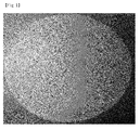
- However, when the phosphor plate is used for a long time, the transmittance of glass may be deteriorated and whitening in which a surface of the phosphor plate becomes hazy may be generated due to a compositional reaction of moisture and the glass in terms of properties of the materials (see
FIG. 1 ). With regard to the whitening, elements based on B, Na, and Li may have an influence on the whitening. However, in particular, it is known that a hydrate is easily formed by Na.FIG. 2 shows a mechanism that a whitening phenomenon is generated by the formation of a hydrate due to moisture and glass elements, in particular, Na. - The present invention has been made keeping in mind the above problems, an aspect of embodiments of the present invention provides a glass composition for a ceramic phosphor plate, and a ceramic phosphor plate including the glass composition, the glass composition including: 75 to 85 mol% of an oxide mixture composed of SiO2, B2O3 and ZnO; 10 to 15 mol% of at least one carbonate compound containing an alkali metal; and 1 to 5 mol% of Al2O3, wherein a content of the B2O3 is less than 25 mol%.
- According to an aspect of embodiments of the present invention, a glass composition for a ceramic phosphor plate may include: 75 to 85 mol% of an oxide mixture composed of SiO2, B2O3 and ZnO; 10 to 15 mol% of at least one carbonate compound containing an alkali metal; and 1 to 5 mol% of Al2O3, wherein a content of the B2O3 is less than 25 mol%.
- Also, according to another aspect of embodiments of the present invention, a ceramic phosphor plate, including a matrix composed of a glass frit having an average particle diameter of 1 to 10 µm obtained by vitrification of the glass composition, and at least one phosphor.
- Also, according to further aspect of embodiments of the present invention, a lighting device may include the ceramic phosphor plate.
- The accompanying drawings are included to provide a further understanding of the present invention, and are incorporated in and constitute a part of this specification. The drawings illustrate exemplary embodiments of the present invention and, together with the description, serve to explain principles of the present invention. In the drawings:
-
FIG. 1 is a photo resulting from capturing a surface of a conventional phosphor plate in which a whitening phenomenon is generated; -
FIG. 2 is a mimetic diagram illustrated for explaining a mechanism in which the conventional phosphor plate causes a whitening phenomenon; -
FIG. 3 is a cross-sectional view illustrating a schematic structure of a lighting device according to an embodiment of the present invention; -
FIG. 4 is a photo resulting from capturing each surface of phosphor plates produced in Examples 1 to 3 after performing a high temperature and humidity test for 1000 hours with regard to the phosphor plates; and -
FIG. 5 is a photo resulting from capturing a front surface (A) and a rear surface (B) of a phosphor plate produced in a comparative example after performing a high temperature and humidity test for 1000 hours with regard to the phosphor plates. - Hereinafter, the embodiments of the present invention that an ordinary person skilled in the art can implement will be described with reference to the accompanying drawings. The embodiments in the specification and the constructions shown in the drawings are provided as a preferred embodiment of the present invention, and it should be understood that there may be various equivalents and modifications which could substitute at the time of filing. In addition, when it comes to the operation principle of the preferred embodiments of the present invention, when the known functions or functions are seemed to make unclear the subject matters of the present invention, they will be omitted from the descriptions of the invention. The terms below are defined in consideration of the functions of the present invention, and the meaning of each term should be interpreted by judging the whole parts of the present specification, and the elements having the similar functions and operations of the drawings are given the same reference numerals. As used herein, the singular forms are intended to include the plural forms as well, unless the context clearly indicates otherwise.
- A glass composition for a ceramic phosphor plate according to an embodiment of the present invention contains: an oxide mixture composed of SiO2, B2O3 and ZnO; at least one carbonate compound including an alkali metal; and Al2O3.
- The oxide mixture composed of the SiO2, B2O3 and ZnO is a material that forms the most basic structure when manufacturing glass via vitrification of the glass composition, and belongs to a network forming oxide or a mesh forming oxide among oxides forming the glass. The oxide mixture is the most basic component of the glass, and ternary glass may be produced with merely the composition.
- The oxide mixture may be contained in an amount of 75 to 85 mol% based on the total amount of the composition. At this time, the ZnO and SiO2 may be mixed at a ratio of 1:1.5 to 1:1.35. The B2O3 contained in the oxide mixture may be contained in an amount of less than 25 mol% based on the total amount of the composition. Despite the fact that B2O3 is a basic material necessary for forming glass, in a case where the B2O3 is used upon manufacturing a phosphor plate for a lighting device, according to an increase in a content of B2O3, optical properties such as reliability, light transmittance and the like may be largely reduced. In particular, the increase in a content of B2O3 may serve as a factor that has a large effect on whitening of the phosphor plate. More preferably, B2O3 may be contained in an amount of less than 15 mol% based on the total amount of the composition. At this time, a ratio of the ZnO to B2O3 may range from 0.35 to 0.75.
- When the phosphor plate is manufactured, the glass frit constituting a matrix of the phosphor plate should have a low glass transition temperature Tg for reducing a sintering temperature. In order to reduce the glass transition temperature Tg, an alkali metal may be contained in the glass composition. In the present embodiment, 10 to 15 mol% of at least one carbonate compound containing an alkali metal is contained in the glass composition. The alkali metal may refer to an element corresponding to group I on the periodic table such as K, Na, Li or the like. A compound such as K2CO3, Na2CO3, Li2CO3, a mixture thereof, or the like may be used as the carbonate compound. A compound resulting from mixing at least two compounds may be used as the carbonate compound. However, when the amount of an alkali metal component in the glass composition is increased, the glass composition may not be glassified, or optical properties of the phosphor plate may be deteriorated. Therefore, it is preferable that a total content of the alkali metal component does not exceed 15 mol%.
- The glass composition includes 1 to 5 mol% of Al2O3. The Al2O3 may improve a crystallization property of the glass composition and may increase a chemical property. Furthermore, The Al2O3 may function to prevent alkali exudation. However, since the Al2O3 is a highly reactive component, it is preferable that a content of the Al2O3 does not exceed 5 mol%.
- As an additional component, P2O5 may be contained in an amount of 5 mol% or less in the glass composition. The P2O5 functions to improve transmittance by promoting phase separation for minute and uniform phase slitting and vitrification. When a content of the B2O3 is reduced, transmittance may be reduced. However, this problem may be improved by adding P2O5. However, since the P2O5 is a highly reactive component, when the P2O5 is added in an excessive amount, there is a possibility of having an influence on reliability. Thus, it is preferable that the content of P2O5 does not exceed 5 mol%.
- The ceramic phosphor plate according to another aspect of the present embodiment may include a matrix composed of a glass frit having an average particle diameter of 1 to 10 µm obtained by vitrification of the glass composition, and at least one phosphor.
- The glass frit is mixed with the glass composition including an oxide mixture composed of SiO2, B2O3 and ZnO, at least one carbonate compound containing an alkali metal, and Al2O3 for 40 to 50 hours using a ball mill, and then the mixture is put in a melting furnace. A melting process can be performed by adjusting a melting temperature according to each compositional condition of the glass composition. At this time, the melting temperature may be 1300 to 1600°C, and glass may be produced according to a conventional glass manufacturing process. The melting process is performed by selecting a temperature for enabling uniform dissolution of the materials contained in the glass composition. At this time, when the temperature is increased by more than 1600 °C, the amount of a volatile component may be increased. The melted material is put in a twin roll and is subjected quenching to prepare a glass cullet. The glass frit is prepared by pulverizing the glass cullet.
- The pulverizing method is divided into a dry pulverization method and a wet pulverization method. Examples of the dry pulverization method include methods using a ball mill, a vibration mill and the like. Al2O3 or ZrO2 is generally used in a ceramic ball used in the ball mill method. Since the vibration mill method uses a vibration movement, the vibration mill has a large impact generated when the vibration mill is caught on a pulverized material. The wet pulverization method is a method of performing pulverization by stirring the pulverized material in a fluid and a ball. The wet pulverization may enable fine pulverizing compared to the dry pulverization. In addition to the ball mill, a medium agitation mill and a bead mill are used. The bead mill is a pulverizer in which a ceramic bead having a diameter of 0.5 to 2.0 mm and high wear resistance is used. An organic solvent such as water or ethanol may be used as the liquid used in the wet pulverization. In the case of glass having high water resistance, water is mainly used. In a case where a change in components may be generated upon using water, an organic solvent may be used.
- The glass frit according to the present embodiment may have an average particle diameter of 1 to 10 µm, preferably, 2 to 7 µm. When the glass frit has a small particle diameter, internal porosity of the glass frit after sintering is reduced so that it can be effective to improve optical properties. In a case where the particle diameter of the glass frit is more than 10 µm, various pores may be formed upon performing sintering by mixing the glass frit with a phosphor later. On the contrary, when the particle diameter of the glass frit is less than 1 µm, the glass frit may not be sufficiently dispersed upon mixing with the phosphor. Thus, passivation of the phosphor may not be sufficiently performed. Furthermore, according to a milling time increase, since the degree of pollution is increased, it is difficult to maintain a whiteness index after sintering.
- According to a desired optical property, the color of lighting, an application field and the like, the ceramic phosphor may be one phosphor of a yellow phosphor, a green phosphor and a red phosphor. According to circumstances, the ceramic phosphor may be at least two kinds of phosphors in which beams having different wavelengths are excited. An yttrium aluminum garnet (YAG)-based phosphor, a lutetium aluminum garnet (LuAG)-based phosphor, a nitride-based phosphor, a sulfide-based phosphor or a silicate-based phosphor may be used as the ceramic phosphor.
- The ceramic phosphor is mixed in an amount of 1 to 15 mol% with respect to the glass frit. At this time, according to each transmittance and color difference after sintering, the amount of the mixed phosphor may be slightly changed. Also, according to the change of a thickness, the content of the phosphor may be changed. When the thickness of the phosphor is increased, the amount of the phosphor may be reduced.
- The mixture of the glass frit and the ceramic phosphor is put into a SUS (Stainless Use Steel) mold and is subjected to uniaxial compression to have a plate or disc form. At this time, the compression is performed at 7 tons for 5 minutes. The mixture of the compressed inorganic phosphor-glass powder is subjected to firing in a state of being put in a firing furnace. A temperature and time for firing may be adjusted according to each glass transition temperature Tg of the inorganic phosphor and the glass powder.
- The ceramic photo-conversion member subjected to sintering may be further subjected to surface polishing in order to adjust a thickness and a surface roughness appropriate for properties required in the embodiment. At this time, the ceramic photo-conversion member is ground until the ceramic photo-conversion member has a thickness of 200 to 1000 µm and a surface roughness of 0.1 to 0.3 µm.
-
FIG. 3 is a cross-sectional view illustrating a schematic structure of a lighting device according to an embodiment of the present invention, - Referring to
FIG. 3 , a lighting device according to the present embodiment of the invention may include theceramic phosphor plate 110. Theceramic phosphor plate 110 is provided to be separated from alight source 120. A separation distance between the ceramic phosphor plate and the light source may range from 10 to 20 mm. Preferably, the separation distance may range from 12 to 18 mm. When the separation distance is more than 20 mm, light extraction may not be sufficiently performed. On the contrary, when the separation distance is less than 10 mm, theceramic phosphor plate 110 may have thermal deformation caused by heat generated from thelight source 120. - The lighting device includes a
housing 130 in which a width is gradually increased upwards from a bottom surface with thelight source 120 as its center. An optical element for emitting light, such as a solid light emitting element, may be applied as thelight source 120. Any one selected from among an LED (Light Emitting Diode), an OLED (Organic Light Emitting Diode), an LD (Laser Diode), a laser, and a VCSEL (Vertical Cavity Surface Emitting Laser) may be applied as the solid light emitting element. Theceramic phosphor plate 110 is provided at an upper end portion of the housing to be separated from thelight source 120. As described above, theceramic phosphor plate 110 includes a matrix composed of a glass frit and a ceramic phosphor dispersed in the matrix. The inside of thehousing 132 may be filled with a material having a higher refractive index than that of the ceramic photo-conversion member 110 or the same refractive index as that of theceramic phosphor plate 110. - Also, an optical property may be measured with an integrating sphere having such a form. Light scattered by the interior of the integrating sphere is evenly distributed over all angles, and the integrating sphere enables the light to be distributed on a surface of the integrating sphere with the regular intensity of illumination by entirely collecting light reflected from the surface of a sample. A special paint, a PTFE (polytetrafluoroethylene) or the like may be used as a coating material for an internal wall of the integrating sphere. The interior of the integrating sphere should not be contaminated. In the case of spectral transmittance, when a light transmitted without a sample is 100%, a ratio for completely blocking light using an opaque object such as an iron plate and the like is 0%. When a transmission color has a large dispersion effect in a transmission material, the optical property may be measured using the integrating sphere.
- The integrating sphere is prepared in a size in which the width WT of ranges from 55 to 60 mm, the width WB of a lower end portion ranges from 35 to 40 mm, and a height H ranges from 15 to 20 mm. First, in a state where there is no
ceramic phosphor plate 110, the radiant flux of a blue LED corresponding to thelight source 120 is measured. Then, theceramic phosphor plate 110 is mounted, and a luminous flux (lumens) is measured. After this, the value of the luminous divided by the value of the radiant flux may give the value of light efficiency. - The present invention will be hereinafter described in greater detail based on examples. The examples have been disclosed for illustrative purposes and the present invention may, however, be embodied in different forms and should not be construed as limited to the examples set forth herein.
- According to compositional conditions indicated in Table 1, weighing of the materials of oxides and a carbonate compound was performed, and thereafter, the materials were put in a ball mill and were then mixed for 48 hours. Mixed powder was put in a platinum crucible and was melted at a temperature of 1300 °C for 30 minutes, and thereafter, the melted material was injected into a twin roller and was subjected to quenching, thereby obtaining a glass cullet. The glass cullet was put into the ball mill again and was pulverized until the glass cullet has a particle diameter of less than 10 µm, thereby obtaining a glass frit.
- 7 mol% of a LuAg phosphor in the range of 530 to 560 nm and 2 mol% of a nitride phosphor in the range of 630 to 690 nm were added to each glass frit produced in Production Examples 1 to 4 and were sufficiently mixed. The obtained mixture was put into a SUS mold (having a molded material thickness of 1000 µm) and was subjected to uniaxial compression at 5 tons for 5 minutes, thereby obtaining a compressed molded material. The compressed molded material was subjected to firing in a firing furnace at a temperature of 630°C for 30 minutes, and was then subjected to mirror-like surface processing so as to have a surface roughness of 0.2 µm, thereby obtaining each phosphor plate.
- The results of measuring transmittance of each phosphor plate are shown in Table 1.
[Table 1] Example 1 Example 2 Example 3 Example 4 ZnO 29 29 29 29 B2O3 21 18 15 15 P2O3 - - - 5 Al2O3 3 3 3 3 K2CO3 10 10 10 10 Na2CO3 3 4 5 3 K2O - - - - Li2CO3 - - - - SiO2 34 36 38 35 Transmittance (%) 46.4 47.6 42.3 51.4 Component Unit: mol%
- Each phosphor plate having compositional conditions as shown in Table 2 below were obtained by the same method as that of the production examples and the examples, and transmittance of each of the phosphor plates was measured.
[Table 2] Comparative Example 1 Comparative Example 2 Comparative Example 3 ZnO 37 37 37 B2O3 30 32 32 P2O3 - - - Al2O3 2 2 2 K2CO3 - - - Na2CO3 - - - K2O 9 9 9 Li2CO3 2 - 2 SiO2 20 - 18 Transmittance (%) 50.7 51.0 51.5 Component Unit: mol%
- Reliability of the phosphor plates of Examples 1, 3 and 4, and Comparative Examples 1 to 3 was verified at an atmosphere pressure of 2, a temperature of 121 °C, and a humidity of 100% (based on JEDEC (Joint Electron Device Engineering Council))
- In the case of the phosphor plates of the comparative examples, whitening was generated within 48 hours. In the case of the phosphor plates of the examples, whitening was generated within at least 96 hours. The results of the reliability test and the measurement of optical properties are shown in Tables 3 and 4.
[Table 3] Blue Example 1 Example 2 Before the Test After the Test Before the Test After the Test Radiant flux (W) 2.7 1.5 1.4 1.6 1.5 1.4 1.4 1.5 1.5 Luminous Flux (lumens) 96.3 477.3 474.0 466.8 455.5 456.2 457.6 453.2 450.7 Color Coordinate (Cx) 0.1526 0.4124 0.421 0.4144 0.4208 0.4281 0.4238 0.4236 0.4289 Color Coordinate (Cy) 0.0291 0.3924 0.3995 0.3926 0.3996 0.3991 0.396 0.3953 0.3997 Color Temperature (K) 0 3345.8 3246.9 3320.8 3252.4 3112.8 3164.7 3164.3 3103.1 Light Efficiency (lm/Wrad) 0 175.4 174.2 175.16 170.92 167.7 168.2 170.06 169.12 CRI (RA) 0 80 79.1 80.3 80 78.8 79.2 80 79.6 Reliability Test (Light Efficiency Δ3% Cx, Cy Δ0.006) shift ΔLight Efficiency: -0.01% ΔLight Efficiency: 1.00% ΔCx: -0.0009 ΔCx: -0.0003 ΔCy: -0.0011 ΔCy: -0.0001 Result PASS PASS [Table 4] Blue Example 4 Before the Test After the Test Radiant flux (W) 2.7 1.4 1.4 1.5 1.5 Luminous Flux (lumens) 96.3 45.3 455.0 445.8 447.8 Color Coordinate (Cx) 0.1526 0.423 0.415 0.4218 0.4155 Color Coordinate (Cy) 0.0291 0.3969 0.3835 0.3952 0.3849 Color Temperature (K) 0 3187.9 3229.4 3197.3 3231.7 Light Efficiency (lm/Wrad) 0 167.7 167.2 167.28 168.03 CRI (RA) 0 79.5 80.5 80.3 81.2 Reliability Test (Light EfficiencyΔ3 % Cx, Cy Δ0.006) shift ΔLight Efficiency: 0.12% ΔCx: -0.0004 ΔCy: -0.0001 - Each of the phosphor plates was left in a high temperature and humidity environment (85 °C and 85%) for 1000 hours pursuant to the requirements for reliability of an LED, and reliability and optical properties thereof were then measured. The results are shown in Tables 5 and 6.
- Also, each surface of the phosphor plates was observed and was illustrated in
FIGS. 4 and5 .FIG. 4 shows a photo resulting from capturing each surface of the phosphor plates after the test performed in the high temperature and humidity for 1000 hours for the phosphor plates produced in Examples 1 to 4, andFIG. 5 is a photo resulting from capturing a front surface (A) and a rear surface (B) of the phosphor plate after the test performed in the high temperature and humidity for 1000 hours for the phosphor plate produced in the comparative examples.[Table 5] 1 2 3 4 5 Before After Before After Before After Before After Before After Radiant flux (W) 1.59 1.5 1.55 1.45 1.45 1.45 1.58 1.44 1.62 1.47 Luminous Flux (lumens) 480.3 484.3 503.7 504.7 499.6 501.6 502.8 501.3 506.9 508.5 Color Coordinate (Cx) 0.4132 0.4153 0.4339 0.4363 0.4371 0.4396 0.434 0.436 0.4312 0.4338 Color Coordinate (Cy) 0.3889 0.3922 0.4267 0.4309 0.4275 0.4315 0.4266 0.4309 0.4236 0.4284 Color Temperature (K) 3314 3299 3226 3215 3178 3167 3223 3220 3249 3240 Light Efficiency (lm/Wrad) 175.0 175.7 183.6 183.1 182.1 182.0 183.2 181.9 184.7 184.5 CRI (RA) 80.5 79.9 76.4 75.3 76.3 75.1 76 75.2 76.6 75.8 Evaluation of reliability ΔCx 0.0021 0.0024 0.0025 0.002 0.0026 [Table 6] 6 7 8 9 10 Before After Before After Before After Before After Before After Radiant flux (W) 1.60 1.47 1.58 1.4 1.58 1.45 1.56 1.43 1.58 1.44 Luminous Flux (lumens) 506.7 509.1 471.1 467.4 471.2 475.4 470.2 471.2 494.9 495.5 Color Coordinate(Cx) 0.4282 0.4311 0.4238 0.4253 0.4293 0.4255 0.4227 0.4258 0.4385 0.4413 Color Coordinate(Cy) 0.4214 0.4263 0.3979 0.4033 0.403 0.4021 0.3981 0.4023 0.4251 0.4299 Color Temperature (K) 3285 3272 3181 3197 3122 3184 3204 3181 3136 3126 Light Efficiency (lm/Wrad) 184.7 184.7 171.7 169.6 171.7 172.5 171.4 171.0 180.4 179.8 CRI (RA) 76.9 75.7 80.3 79.1 78.9 79.3 79.7 79.3 76.8 76.2 Evaluation of reliability ΔCx 0.0029 0.0015 -0.0038 0.0031 0.0028 ΔCy 0.0049 0.0054 -0.0009 0.0042 0.0048 ΔEfficiency 0.04% -1.22% 0.45% -0.22% -0.31% Result PASS PASS PASS PASS PASS - As set forth above, according to some embodiment of the present invention, a ceramic phosphor plate having high reliability can be implemented using a glass composition for the ceramic phosphor plate, including: 75 to 85 mol% of an oxide mixture composed of SiO2, B2O3 and ZnO; 10 to 15 mol% of at least one carbonate compound including an alkali metal; and 1 to 5 mol% of Al2O3, wherein a content of B2O3 is less than 25 mol%. Thus, even though the ceramic phosphor plate is exposed in a high temperature and humidity environment, whitening of the ceramic phosphor plate can be prevented, and the ceramic phosphor plate can have high reliability and high optical properties.
- As previously described, in the detailed description of the invention, having described the detailed exemplary embodiments of the invention, it should be apparent that modifications and variations can be made by persons skilled without deviating from the spirit or scope of the invention. Therefore, it is to be understood that the foregoing is illustrative of the present invention and is not to be construed as limited to the specific embodiments disclosed, and that modifications to the disclosed embodiments, as well as other embodiments, are intended to be included within the scope of the appended claims and their equivalents.
Claims (15)
- A glass composition for a ceramic phosphor plate, comprising:75 to 85 mol% of an oxide mixture composed of SiO2, B2O3 and ZnO;10 to 15 mol% of at least one carbonate compound including an alkali metal; and1 to 5 mol% of Al2O3,
wherein a content of B2O3 is less than 25 mol%. - The glass composition of claim 1, wherein a ratio of the ZnO to B2O3 ranges from 0.35 to 0.75.
- The glass composition of claim 1 or 2, further comprising 5 mol% or less of an additional component.
- The glass composition of claim 3, wherein the additional component is P2O5.
- The glass composition of any one of claims 1 to 4, wherein the carbonate compound is at least one compound selected from the group consisting of K2CO3, Na2CO3, Li2CO3 and a mixture thereof.
- The glass composition of any one of claims 1 to 5, wherein the alkali metal is any one of K, Na, and Li.
- The glass composition of any one of claims 1 to 6, wherein a content of the B2O3 is less than 15 mol%.
- A ceramic phosphor plate, comprising:a matrix composed of a glass frit having an average particle diameter of 1 to 10 µm obtained by vitrification of a glass composition of any one of claims 1 to 7; andat least one phosphor.
- The ceramic phosphor plate of claim 8, wherein the phosphor is at least one phosphor selected from the group consisting of an yttrium aluminum garnet (YAG)-based phosphor, a lutetium aluminum garnet (LuAG)-based phosphor, a nitride-based phosphor, a sulfide-based phosphor, a silicate-based phosphor, and a mixture thereof.
- The ceramic phosphor plate of claim 8 or 9, wherein the phosphor is contained in an amount of 1 to 15 mol% in a mixture containing the glass frit and the phosphor.
- A lighting device, comprising:a ceramic phosphor plate of any one of claims 8 to 10.
- The lighting device of claim 11, further comprising:a light source emitting light, wherein the ceramic phosphor plate is disposed to be separated from the light source; anda housing in which the light source and the ceramic phosphor plate are accommodated.
- The lighting device of claim 11 or 12, wherein the housing has a structure in which a width of the housing is gradually increased upwards from a bottom portion at which the light source is disposed.
- The lighting device of claim 13, further comprising a filling material filled in the inside of the housing and having a higher refractive index than that of the ceramic phosphor plate.
- The lighting device of any one of claims 12 to 14, wherein a separation distance between the ceramic phosphor plate and the light source ranges from 10 to 20 mm.
Applications Claiming Priority (1)
| Application Number | Priority Date | Filing Date | Title |
|---|---|---|---|
| KR1020140014780A KR102201048B1 (en) | 2014-02-10 | 2014-02-10 | Glass composition for high-reliability ceramic phosphor plate and ceramic phosphor plate using the same |
Publications (2)
| Publication Number | Publication Date |
|---|---|
| EP2905266A1 true EP2905266A1 (en) | 2015-08-12 |
| EP2905266B1 EP2905266B1 (en) | 2019-12-18 |
Family
ID=52469641
Family Applications (1)
| Application Number | Title | Priority Date | Filing Date |
|---|---|---|---|
| EP15154524.1A Active EP2905266B1 (en) | 2014-02-10 | 2015-02-10 | Method for producing high-reliability ceramic phoshpor plate |
Country Status (4)
| Country | Link |
|---|---|
| US (1) | US9403713B2 (en) |
| EP (1) | EP2905266B1 (en) |
| KR (1) | KR102201048B1 (en) |
| CN (1) | CN104829129B (en) |
Cited By (2)
| Publication number | Priority date | Publication date | Assignee | Title |
|---|---|---|---|---|
| EP2942824A1 (en) * | 2014-01-29 | 2015-11-11 | LG Innotek Co., Ltd. | Glass composition for photo-conversion member and ceramic photo-conversion member using the same |
| EP3050857A1 (en) * | 2015-02-02 | 2016-08-03 | Ferro Corporation | Glass compositions and glass frit composites for use in optical applications |
Families Citing this family (6)
| Publication number | Priority date | Publication date | Assignee | Title |
|---|---|---|---|---|
| KR101964418B1 (en) * | 2012-07-02 | 2019-04-01 | 엘지이노텍 주식회사 | Phosphor composition and lighting device the same |
| KR102459950B1 (en) * | 2015-12-22 | 2022-10-27 | 엘지이노텍 주식회사 | Phosphor plate package |
| KR102149988B1 (en) * | 2018-09-07 | 2020-08-31 | 대주전자재료 주식회사 | Laminated body for preparing wavelength conversion member and preparation method of wavelength conversion member |
| KR102826140B1 (en) * | 2020-03-18 | 2025-06-27 | 덴카 주식회사 | Phosphor plates and luminescent devices |
| KR102697011B1 (en) * | 2024-04-30 | 2024-08-22 | (주)우석에이티 | Method for Manufacturing Ceramic Phosphor Plate for Light Conversion Medium and Ceramic Phosphor Plate Manufactured Therefrom |
| KR102742482B1 (en) | 2024-04-30 | 2024-12-17 | (주)우석에이티 | Alumina-Based Composition for Light Converting Medium and Ceramic Phosphor Plate Comprising the Same |
Citations (7)
| Publication number | Priority date | Publication date | Assignee | Title |
|---|---|---|---|---|
| US3461078A (en) * | 1966-11-22 | 1969-08-12 | Owens Illinois Inc | Crystalline luminescent ceramic materials |
| JP2001199737A (en) * | 1999-04-21 | 2001-07-24 | Mitsubishi Materials Corp | Glass composition and mixture thereof, and paste, green sheet, insulator, dielectric, thick film and FPD using the same |
| US20050113241A1 (en) * | 2003-11-06 | 2005-05-26 | Asahi Glass Company, Limited | Glass for forming barrier ribs, and plasma display panel |
| US20050231118A1 (en) * | 2003-07-18 | 2005-10-20 | Asahi Glass Company Limited | Non-lead glass, glass powder for covering electrodes and plasma display device |
| US20070078047A1 (en) * | 2005-10-05 | 2007-04-05 | Asahi Glass Company, Limited | Glass for covering electrodes and plasma display panel |
| JP2007217271A (en) * | 2006-01-17 | 2007-08-30 | Asahi Glass Co Ltd | Electrode coating glass and plasma display device |
| US20080081198A1 (en) * | 2004-12-21 | 2008-04-03 | Asahi Glass Company, Limited | Glass for covering electrode |
Family Cites Families (10)
| Publication number | Priority date | Publication date | Assignee | Title |
|---|---|---|---|---|
| JP3696725B2 (en) * | 1997-09-19 | 2005-09-21 | 日本山村硝子株式会社 | Glass composition for photosensitive glass paste |
| JP2005047732A (en) * | 2003-07-31 | 2005-02-24 | Minolta Co Ltd | Optical glass and optical element |
| WO2006120827A1 (en) * | 2005-05-11 | 2006-11-16 | Nippon Electric Glass Co., Ltd. | Fluorescent substance composite glass, fluorescent substance composite glass green sheet, and process for producing fluorescent substance composite glass |
| JP2007191702A (en) * | 2005-12-22 | 2007-08-02 | Nippon Electric Glass Co Ltd | Light emission color converting material |
| JP5483795B2 (en) * | 2006-04-11 | 2014-05-07 | 日本電気硝子株式会社 | Luminescent color conversion material and luminescent color conversion member |
| JP2007332009A (en) * | 2006-06-19 | 2007-12-27 | Noritake Co Ltd | Lead-free insulating glass composition and lead-free insulating glass paste |
| DE102008021438A1 (en) * | 2008-04-29 | 2009-12-31 | Schott Ag | Conversion material in particular for a, a semiconductor light source comprising white or colored light source, method for its preparation and this conversion material comprising light source |
| CN101643315B (en) * | 2009-08-10 | 2012-02-08 | 武汉理工大学 | Low-melting-point fluorescent glass for white light LED and preparation method thereof |
| JP2012158494A (en) * | 2011-01-31 | 2012-08-23 | Ohara Inc | Glass composition |
| JP6149309B2 (en) * | 2012-03-30 | 2017-06-21 | コーニング インコーポレイテッド | Bismuth borate glass sealant for LED phosphor |
-
2014
- 2014-02-10 KR KR1020140014780A patent/KR102201048B1/en active Active
-
2015
- 2015-02-10 CN CN201510070491.1A patent/CN104829129B/en active Active
- 2015-02-10 US US14/618,034 patent/US9403713B2/en active Active
- 2015-02-10 EP EP15154524.1A patent/EP2905266B1/en active Active
Patent Citations (7)
| Publication number | Priority date | Publication date | Assignee | Title |
|---|---|---|---|---|
| US3461078A (en) * | 1966-11-22 | 1969-08-12 | Owens Illinois Inc | Crystalline luminescent ceramic materials |
| JP2001199737A (en) * | 1999-04-21 | 2001-07-24 | Mitsubishi Materials Corp | Glass composition and mixture thereof, and paste, green sheet, insulator, dielectric, thick film and FPD using the same |
| US20050231118A1 (en) * | 2003-07-18 | 2005-10-20 | Asahi Glass Company Limited | Non-lead glass, glass powder for covering electrodes and plasma display device |
| US20050113241A1 (en) * | 2003-11-06 | 2005-05-26 | Asahi Glass Company, Limited | Glass for forming barrier ribs, and plasma display panel |
| US20080081198A1 (en) * | 2004-12-21 | 2008-04-03 | Asahi Glass Company, Limited | Glass for covering electrode |
| US20070078047A1 (en) * | 2005-10-05 | 2007-04-05 | Asahi Glass Company, Limited | Glass for covering electrodes and plasma display panel |
| JP2007217271A (en) * | 2006-01-17 | 2007-08-30 | Asahi Glass Co Ltd | Electrode coating glass and plasma display device |
Cited By (3)
| Publication number | Priority date | Publication date | Assignee | Title |
|---|---|---|---|---|
| EP2942824A1 (en) * | 2014-01-29 | 2015-11-11 | LG Innotek Co., Ltd. | Glass composition for photo-conversion member and ceramic photo-conversion member using the same |
| US9840663B2 (en) | 2014-01-29 | 2017-12-12 | Lg Innotek Co., Ltd | Glass composition for photo-conversion member and ceramic photo-conversion member using the same |
| EP3050857A1 (en) * | 2015-02-02 | 2016-08-03 | Ferro Corporation | Glass compositions and glass frit composites for use in optical applications |
Also Published As
| Publication number | Publication date |
|---|---|
| KR102201048B1 (en) | 2021-01-12 |
| US20150225281A1 (en) | 2015-08-13 |
| US9403713B2 (en) | 2016-08-02 |
| KR20150094812A (en) | 2015-08-20 |
| CN104829129B (en) | 2019-06-04 |
| CN104829129A (en) | 2015-08-12 |
| EP2905266B1 (en) | 2019-12-18 |
Similar Documents
| Publication | Publication Date | Title |
|---|---|---|
| EP2905266B1 (en) | Method for producing high-reliability ceramic phoshpor plate | |
| US9840663B2 (en) | Glass composition for photo-conversion member and ceramic photo-conversion member using the same | |
| JP5757238B2 (en) | Phosphor-dispersed glass and method for producing the same | |
| US20210230047A1 (en) | Wavelength conversion member, and light emitting device using same | |
| KR102588721B1 (en) | Wavelength conversion member, and light emitting device using same | |
| US20160152515A1 (en) | Phosphor-Dispersed Glass and Method for Producing Same | |
| KR20160098176A (en) | Wavelength-conversion member and light-emitting device | |
| KR101559279B1 (en) | A phosphor composition containing a glass frit | |
| KR102187046B1 (en) | Glass composition for photo-conversing medium and ceramic phosphor plate including the same | |
| KR102449767B1 (en) | Composition for Manufacturing Ceramic Fluorescent Plate, Ceramic Fluorescent Plate and Light Emitting Apparatus | |
| KR102318233B1 (en) | Composition for Manufacturing Ceramic Fluorescent Plate, Ceramic Fluorescent Plate and Light Emitting Apparatus | |
| KR102318228B1 (en) | Lighting device | |
| KR102787455B1 (en) | High Refractive Index Glass Frit Composition Including a Phosphor and Method for Manufacturing the Same | |
| KR20210055919A (en) | High Refractive Index Glass Frit Composition Including a Phosphor and a Ceramic Plate for Light Emission Including the Same | |
| KR102228380B1 (en) | Glass composition for ceramic photo-conversing part and ceramic photo-conversing part including the same | |
| KR102584893B1 (en) | Glass Frit Composition Including a Phosphor and Method for Manufacturing the Same | |
| KR102394051B1 (en) | Composition for Manufacturing Ceramic Fluorescent Plate, Ceramic Fluorescent Plate and Light Emitting Apparatus | |
| KR102187045B1 (en) | Glass composition for ceramic photo-conversion part and ceramic photo-conversion part using the same | |
| US11999648B2 (en) | Wavelength conversion member and light emitting device using same | |
| KR102291731B1 (en) | Wavelength converting ceramic medium |
Legal Events
| Date | Code | Title | Description |
|---|---|---|---|
| PUAI | Public reference made under article 153(3) epc to a published international application that has entered the european phase |
Free format text: ORIGINAL CODE: 0009012 |
|
| AK | Designated contracting states |
Kind code of ref document: A1 Designated state(s): AL AT BE BG CH CY CZ DE DK EE ES FI FR GB GR HR HU IE IS IT LI LT LU LV MC MK MT NL NO PL PT RO RS SE SI SK SM TR |
|
| AX | Request for extension of the european patent |
Extension state: BA ME |
|
| 17P | Request for examination filed |
Effective date: 20160129 |
|
| RBV | Designated contracting states (corrected) |
Designated state(s): AL AT BE BG CH CY CZ DE DK EE ES FI FR GB GR HR HU IE IS IT LI LT LU LV MC MK MT NL NO PL PT RO RS SE SI SK SM TR |
|
| RAP1 | Party data changed (applicant data changed or rights of an application transferred) |
Owner name: LG INNOTEK CO., LTD. Owner name: DAE JOO ELECTRONIC MATERIALS CO., LTD. |
|
| STAA | Information on the status of an ep patent application or granted ep patent |
Free format text: STATUS: EXAMINATION IS IN PROGRESS |
|
| 17Q | First examination report despatched |
Effective date: 20180108 |
|
| GRAP | Despatch of communication of intention to grant a patent |
Free format text: ORIGINAL CODE: EPIDOSNIGR1 |
|
| STAA | Information on the status of an ep patent application or granted ep patent |
Free format text: STATUS: GRANT OF PATENT IS INTENDED |
|
| INTG | Intention to grant announced |
Effective date: 20190719 |
|
| GRAS | Grant fee paid |
Free format text: ORIGINAL CODE: EPIDOSNIGR3 |
|
| GRAA | (expected) grant |
Free format text: ORIGINAL CODE: 0009210 |
|
| STAA | Information on the status of an ep patent application or granted ep patent |
Free format text: STATUS: THE PATENT HAS BEEN GRANTED |
|
| AK | Designated contracting states |
Kind code of ref document: B1 Designated state(s): AL AT BE BG CH CY CZ DE DK EE ES FI FR GB GR HR HU IE IS IT LI LT LU LV MC MK MT NL NO PL PT RO RS SE SI SK SM TR |
|
| REG | Reference to a national code |
Ref country code: CH Ref legal event code: EP |
|
| REG | Reference to a national code |
Ref country code: DE Ref legal event code: R096 Ref document number: 602015043702 Country of ref document: DE |
|
| REG | Reference to a national code |
Ref country code: IE Ref legal event code: FG4D |
|
| REG | Reference to a national code |
Ref country code: AT Ref legal event code: REF Ref document number: 1214424 Country of ref document: AT Kind code of ref document: T Effective date: 20200115 |
|
| REG | Reference to a national code |
Ref country code: NL Ref legal event code: MP Effective date: 20191218 |
|
| PG25 | Lapsed in a contracting state [announced via postgrant information from national office to epo] |
Ref country code: SE Free format text: LAPSE BECAUSE OF FAILURE TO SUBMIT A TRANSLATION OF THE DESCRIPTION OR TO PAY THE FEE WITHIN THE PRESCRIBED TIME-LIMIT Effective date: 20191218 Ref country code: LV Free format text: LAPSE BECAUSE OF FAILURE TO SUBMIT A TRANSLATION OF THE DESCRIPTION OR TO PAY THE FEE WITHIN THE PRESCRIBED TIME-LIMIT Effective date: 20191218 Ref country code: LT Free format text: LAPSE BECAUSE OF FAILURE TO SUBMIT A TRANSLATION OF THE DESCRIPTION OR TO PAY THE FEE WITHIN THE PRESCRIBED TIME-LIMIT Effective date: 20191218 Ref country code: GR Free format text: LAPSE BECAUSE OF FAILURE TO SUBMIT A TRANSLATION OF THE DESCRIPTION OR TO PAY THE FEE WITHIN THE PRESCRIBED TIME-LIMIT Effective date: 20200319 Ref country code: NO Free format text: LAPSE BECAUSE OF FAILURE TO SUBMIT A TRANSLATION OF THE DESCRIPTION OR TO PAY THE FEE WITHIN THE PRESCRIBED TIME-LIMIT Effective date: 20200318 Ref country code: BG Free format text: LAPSE BECAUSE OF FAILURE TO SUBMIT A TRANSLATION OF THE DESCRIPTION OR TO PAY THE FEE WITHIN THE PRESCRIBED TIME-LIMIT Effective date: 20200318 Ref country code: FI Free format text: LAPSE BECAUSE OF FAILURE TO SUBMIT A TRANSLATION OF THE DESCRIPTION OR TO PAY THE FEE WITHIN THE PRESCRIBED TIME-LIMIT Effective date: 20191218 |
|
| REG | Reference to a national code |
Ref country code: LT Ref legal event code: MG4D |
|
| PG25 | Lapsed in a contracting state [announced via postgrant information from national office to epo] |
Ref country code: HR Free format text: LAPSE BECAUSE OF FAILURE TO SUBMIT A TRANSLATION OF THE DESCRIPTION OR TO PAY THE FEE WITHIN THE PRESCRIBED TIME-LIMIT Effective date: 20191218 Ref country code: RS Free format text: LAPSE BECAUSE OF FAILURE TO SUBMIT A TRANSLATION OF THE DESCRIPTION OR TO PAY THE FEE WITHIN THE PRESCRIBED TIME-LIMIT Effective date: 20191218 |
|
| PG25 | Lapsed in a contracting state [announced via postgrant information from national office to epo] |
Ref country code: AL Free format text: LAPSE BECAUSE OF FAILURE TO SUBMIT A TRANSLATION OF THE DESCRIPTION OR TO PAY THE FEE WITHIN THE PRESCRIBED TIME-LIMIT Effective date: 20191218 |
|
| PG25 | Lapsed in a contracting state [announced via postgrant information from national office to epo] |
Ref country code: CZ Free format text: LAPSE BECAUSE OF FAILURE TO SUBMIT A TRANSLATION OF THE DESCRIPTION OR TO PAY THE FEE WITHIN THE PRESCRIBED TIME-LIMIT Effective date: 20191218 Ref country code: RO Free format text: LAPSE BECAUSE OF FAILURE TO SUBMIT A TRANSLATION OF THE DESCRIPTION OR TO PAY THE FEE WITHIN THE PRESCRIBED TIME-LIMIT Effective date: 20191218 Ref country code: PT Free format text: LAPSE BECAUSE OF FAILURE TO SUBMIT A TRANSLATION OF THE DESCRIPTION OR TO PAY THE FEE WITHIN THE PRESCRIBED TIME-LIMIT Effective date: 20200513 Ref country code: NL Free format text: LAPSE BECAUSE OF FAILURE TO SUBMIT A TRANSLATION OF THE DESCRIPTION OR TO PAY THE FEE WITHIN THE PRESCRIBED TIME-LIMIT Effective date: 20191218 Ref country code: EE Free format text: LAPSE BECAUSE OF FAILURE TO SUBMIT A TRANSLATION OF THE DESCRIPTION OR TO PAY THE FEE WITHIN THE PRESCRIBED TIME-LIMIT Effective date: 20191218 |
|
| PG25 | Lapsed in a contracting state [announced via postgrant information from national office to epo] |
Ref country code: IS Free format text: LAPSE BECAUSE OF FAILURE TO SUBMIT A TRANSLATION OF THE DESCRIPTION OR TO PAY THE FEE WITHIN THE PRESCRIBED TIME-LIMIT Effective date: 20200418 Ref country code: SK Free format text: LAPSE BECAUSE OF FAILURE TO SUBMIT A TRANSLATION OF THE DESCRIPTION OR TO PAY THE FEE WITHIN THE PRESCRIBED TIME-LIMIT Effective date: 20191218 Ref country code: SM Free format text: LAPSE BECAUSE OF FAILURE TO SUBMIT A TRANSLATION OF THE DESCRIPTION OR TO PAY THE FEE WITHIN THE PRESCRIBED TIME-LIMIT Effective date: 20191218 |
|
| REG | Reference to a national code |
Ref country code: DE Ref legal event code: R097 Ref document number: 602015043702 Country of ref document: DE |
|
| REG | Reference to a national code |
Ref country code: CH Ref legal event code: PL |
|
| REG | Reference to a national code |
Ref country code: AT Ref legal event code: MK05 Ref document number: 1214424 Country of ref document: AT Kind code of ref document: T Effective date: 20191218 |
|
| PLBE | No opposition filed within time limit |
Free format text: ORIGINAL CODE: 0009261 |
|
| STAA | Information on the status of an ep patent application or granted ep patent |
Free format text: STATUS: NO OPPOSITION FILED WITHIN TIME LIMIT |
|
| REG | Reference to a national code |
Ref country code: BE Ref legal event code: MM Effective date: 20200229 |
|
| PG25 | Lapsed in a contracting state [announced via postgrant information from national office to epo] |
Ref country code: LU Free format text: LAPSE BECAUSE OF NON-PAYMENT OF DUE FEES Effective date: 20200210 Ref country code: MC Free format text: LAPSE BECAUSE OF FAILURE TO SUBMIT A TRANSLATION OF THE DESCRIPTION OR TO PAY THE FEE WITHIN THE PRESCRIBED TIME-LIMIT Effective date: 20191218 Ref country code: ES Free format text: LAPSE BECAUSE OF FAILURE TO SUBMIT A TRANSLATION OF THE DESCRIPTION OR TO PAY THE FEE WITHIN THE PRESCRIBED TIME-LIMIT Effective date: 20191218 Ref country code: DK Free format text: LAPSE BECAUSE OF FAILURE TO SUBMIT A TRANSLATION OF THE DESCRIPTION OR TO PAY THE FEE WITHIN THE PRESCRIBED TIME-LIMIT Effective date: 20191218 |
|
| 26N | No opposition filed |
Effective date: 20200921 |
|
| PG25 | Lapsed in a contracting state [announced via postgrant information from national office to epo] |
Ref country code: SI Free format text: LAPSE BECAUSE OF FAILURE TO SUBMIT A TRANSLATION OF THE DESCRIPTION OR TO PAY THE FEE WITHIN THE PRESCRIBED TIME-LIMIT Effective date: 20191218 Ref country code: CH Free format text: LAPSE BECAUSE OF NON-PAYMENT OF DUE FEES Effective date: 20200229 Ref country code: AT Free format text: LAPSE BECAUSE OF FAILURE TO SUBMIT A TRANSLATION OF THE DESCRIPTION OR TO PAY THE FEE WITHIN THE PRESCRIBED TIME-LIMIT Effective date: 20191218 Ref country code: LI Free format text: LAPSE BECAUSE OF NON-PAYMENT OF DUE FEES Effective date: 20200229 |
|
| PG25 | Lapsed in a contracting state [announced via postgrant information from national office to epo] |
Ref country code: IE Free format text: LAPSE BECAUSE OF NON-PAYMENT OF DUE FEES Effective date: 20200210 Ref country code: FR Free format text: LAPSE BECAUSE OF NON-PAYMENT OF DUE FEES Effective date: 20200218 Ref country code: IT Free format text: LAPSE BECAUSE OF FAILURE TO SUBMIT A TRANSLATION OF THE DESCRIPTION OR TO PAY THE FEE WITHIN THE PRESCRIBED TIME-LIMIT Effective date: 20191218 |
|
| PG25 | Lapsed in a contracting state [announced via postgrant information from national office to epo] |
Ref country code: BE Free format text: LAPSE BECAUSE OF NON-PAYMENT OF DUE FEES Effective date: 20200229 Ref country code: PL Free format text: LAPSE BECAUSE OF FAILURE TO SUBMIT A TRANSLATION OF THE DESCRIPTION OR TO PAY THE FEE WITHIN THE PRESCRIBED TIME-LIMIT Effective date: 20191218 |
|
| PG25 | Lapsed in a contracting state [announced via postgrant information from national office to epo] |
Ref country code: TR Free format text: LAPSE BECAUSE OF FAILURE TO SUBMIT A TRANSLATION OF THE DESCRIPTION OR TO PAY THE FEE WITHIN THE PRESCRIBED TIME-LIMIT Effective date: 20191218 Ref country code: MT Free format text: LAPSE BECAUSE OF FAILURE TO SUBMIT A TRANSLATION OF THE DESCRIPTION OR TO PAY THE FEE WITHIN THE PRESCRIBED TIME-LIMIT Effective date: 20191218 Ref country code: CY Free format text: LAPSE BECAUSE OF FAILURE TO SUBMIT A TRANSLATION OF THE DESCRIPTION OR TO PAY THE FEE WITHIN THE PRESCRIBED TIME-LIMIT Effective date: 20191218 |
|
| PG25 | Lapsed in a contracting state [announced via postgrant information from national office to epo] |
Ref country code: MK Free format text: LAPSE BECAUSE OF FAILURE TO SUBMIT A TRANSLATION OF THE DESCRIPTION OR TO PAY THE FEE WITHIN THE PRESCRIBED TIME-LIMIT Effective date: 20191218 |
|
| PGFP | Annual fee paid to national office [announced via postgrant information from national office to epo] |
Ref country code: GB Payment date: 20251222 Year of fee payment: 12 |
|
| PGFP | Annual fee paid to national office [announced via postgrant information from national office to epo] |
Ref country code: DE Payment date: 20251222 Year of fee payment: 12 |