EP2905173A1 - Load control unit - Google Patents
Load control unit Download PDFInfo
- Publication number
- EP2905173A1 EP2905173A1 EP13843513.6A EP13843513A EP2905173A1 EP 2905173 A1 EP2905173 A1 EP 2905173A1 EP 13843513 A EP13843513 A EP 13843513A EP 2905173 A1 EP2905173 A1 EP 2905173A1
- Authority
- EP
- European Patent Office
- Prior art keywords
- controller
- seat
- control unit
- connector
- built
- Prior art date
- Legal status (The legal status is an assumption and is not a legal conclusion. Google has not performed a legal analysis and makes no representation as to the accuracy of the status listed.)
- Granted
Links
Images



Classifications
-
- B—PERFORMING OPERATIONS; TRANSPORTING
- B60—VEHICLES IN GENERAL
- B60R—VEHICLES, VEHICLE FITTINGS, OR VEHICLE PARTS, NOT OTHERWISE PROVIDED FOR
- B60R16/00—Electric or fluid circuits specially adapted for vehicles and not otherwise provided for; Arrangement of elements of electric or fluid circuits specially adapted for vehicles and not otherwise provided for
- B60R16/02—Electric or fluid circuits specially adapted for vehicles and not otherwise provided for; Arrangement of elements of electric or fluid circuits specially adapted for vehicles and not otherwise provided for electric constitutive elements
-
- B—PERFORMING OPERATIONS; TRANSPORTING
- B60—VEHICLES IN GENERAL
- B60Q—ARRANGEMENT OF SIGNALLING OR LIGHTING DEVICES, THE MOUNTING OR SUPPORTING THEREOF OR CIRCUITS THEREFOR, FOR VEHICLES IN GENERAL
- B60Q3/00—Arrangement of lighting devices for vehicle interiors; Lighting devices specially adapted for vehicle interiors
- B60Q3/20—Arrangement of lighting devices for vehicle interiors; Lighting devices specially adapted for vehicle interiors for lighting specific fittings of passenger or driving compartments; mounted on specific fittings of passenger or driving compartments
- B60Q3/233—Seats; Arm rests; Head rests
-
- B—PERFORMING OPERATIONS; TRANSPORTING
- B60—VEHICLES IN GENERAL
- B60Q—ARRANGEMENT OF SIGNALLING OR LIGHTING DEVICES, THE MOUNTING OR SUPPORTING THEREOF OR CIRCUITS THEREFOR, FOR VEHICLES IN GENERAL
- B60Q3/00—Arrangement of lighting devices for vehicle interiors; Lighting devices specially adapted for vehicle interiors
- B60Q3/70—Arrangement of lighting devices for vehicle interiors; Lighting devices specially adapted for vehicle interiors characterised by the purpose
- B60Q3/76—Arrangement of lighting devices for vehicle interiors; Lighting devices specially adapted for vehicle interiors characterised by the purpose for spotlighting, e.g. reading lamps
-
- B—PERFORMING OPERATIONS; TRANSPORTING
- B60—VEHICLES IN GENERAL
- B60Q—ARRANGEMENT OF SIGNALLING OR LIGHTING DEVICES, THE MOUNTING OR SUPPORTING THEREOF OR CIRCUITS THEREFOR, FOR VEHICLES IN GENERAL
- B60Q3/00—Arrangement of lighting devices for vehicle interiors; Lighting devices specially adapted for vehicle interiors
- B60Q3/80—Circuits; Control arrangements
-
- B—PERFORMING OPERATIONS; TRANSPORTING
- B60—VEHICLES IN GENERAL
- B60R—VEHICLES, VEHICLE FITTINGS, OR VEHICLE PARTS, NOT OTHERWISE PROVIDED FOR
- B60R22/00—Safety belts or body harnesses in vehicles
- B60R22/48—Control systems, alarms, or interlock systems, for the correct application of the belt or harness
-
- H—ELECTRICITY
- H01—ELECTRIC ELEMENTS
- H01R—ELECTRICALLY-CONDUCTIVE CONNECTIONS; STRUCTURAL ASSOCIATIONS OF A PLURALITY OF MUTUALLY-INSULATED ELECTRICAL CONNECTING ELEMENTS; COUPLING DEVICES; CURRENT COLLECTORS
- H01R13/00—Details of coupling devices of the kinds covered by groups H01R12/70 or H01R24/00 - H01R33/00
- H01R13/66—Structural association with built-in electrical component
- H01R13/665—Structural association with built-in electrical component with built-in electronic circuit
- H01R13/6658—Structural association with built-in electrical component with built-in electronic circuit on printed circuit board
-
- H—ELECTRICITY
- H05—ELECTRIC TECHNIQUES NOT OTHERWISE PROVIDED FOR
- H05B—ELECTRIC HEATING; ELECTRIC LIGHT SOURCES NOT OTHERWISE PROVIDED FOR; CIRCUIT ARRANGEMENTS FOR ELECTRIC LIGHT SOURCES, IN GENERAL
- H05B45/00—Circuit arrangements for operating light-emitting diodes [LED]
- H05B45/20—Controlling the colour of the light
-
- H—ELECTRICITY
- H05—ELECTRIC TECHNIQUES NOT OTHERWISE PROVIDED FOR
- H05B—ELECTRIC HEATING; ELECTRIC LIGHT SOURCES NOT OTHERWISE PROVIDED FOR; CIRCUIT ARRANGEMENTS FOR ELECTRIC LIGHT SOURCES, IN GENERAL
- H05B47/00—Circuit arrangements for operating light sources in general, i.e. where the type of light source is not relevant
- H05B47/10—Controlling the light source
- H05B47/175—Controlling the light source by remote control
- H05B47/18—Controlling the light source by remote control via data-bus transmission
-
- H—ELECTRICITY
- H05—ELECTRIC TECHNIQUES NOT OTHERWISE PROVIDED FOR
- H05B—ELECTRIC HEATING; ELECTRIC LIGHT SOURCES NOT OTHERWISE PROVIDED FOR; CIRCUIT ARRANGEMENTS FOR ELECTRIC LIGHT SOURCES, IN GENERAL
- H05B47/00—Circuit arrangements for operating light sources in general, i.e. where the type of light source is not relevant
- H05B47/10—Controlling the light source
- H05B47/175—Controlling the light source by remote control
- H05B47/198—Grouping of control procedures or address assignation to light sources
- H05B47/1985—Creation of lighting zones or scenes
-
- B—PERFORMING OPERATIONS; TRANSPORTING
- B60—VEHICLES IN GENERAL
- B60Q—ARRANGEMENT OF SIGNALLING OR LIGHTING DEVICES, THE MOUNTING OR SUPPORTING THEREOF OR CIRCUITS THEREFOR, FOR VEHICLES IN GENERAL
- B60Q2500/00—Special features or arrangements of vehicle interior lamps
- B60Q2500/30—Arrangements for illuminating different zones in the vehicle, e.g. front/rear, different seats
-
- B—PERFORMING OPERATIONS; TRANSPORTING
- B60—VEHICLES IN GENERAL
- B60R—VEHICLES, VEHICLE FITTINGS, OR VEHICLE PARTS, NOT OTHERWISE PROVIDED FOR
- B60R22/00—Safety belts or body harnesses in vehicles
- B60R22/48—Control systems, alarms, or interlock systems, for the correct application of the belt or harness
- B60R2022/4808—Sensing means arrangements therefor
- B60R2022/4816—Sensing means arrangements therefor for sensing locking of buckle
-
- B—PERFORMING OPERATIONS; TRANSPORTING
- B60—VEHICLES IN GENERAL
- B60R—VEHICLES, VEHICLE FITTINGS, OR VEHICLE PARTS, NOT OTHERWISE PROVIDED FOR
- B60R22/00—Safety belts or body harnesses in vehicles
- B60R22/48—Control systems, alarms, or interlock systems, for the correct application of the belt or harness
- B60R2022/4808—Sensing means arrangements therefor
- B60R2022/4858—Sensing means arrangements therefor for sensing pressure on seat
-
- B—PERFORMING OPERATIONS; TRANSPORTING
- B60—VEHICLES IN GENERAL
- B60R—VEHICLES, VEHICLE FITTINGS, OR VEHICLE PARTS, NOT OTHERWISE PROVIDED FOR
- B60R22/00—Safety belts or body harnesses in vehicles
- B60R22/48—Control systems, alarms, or interlock systems, for the correct application of the belt or harness
- B60R2022/4866—Displaying or indicating arrangements thereof
-
- H—ELECTRICITY
- H01—ELECTRIC ELEMENTS
- H01R—ELECTRICALLY-CONDUCTIVE CONNECTIONS; STRUCTURAL ASSOCIATIONS OF A PLURALITY OF MUTUALLY-INSULATED ELECTRICAL CONNECTING ELEMENTS; COUPLING DEVICES; CURRENT COLLECTORS
- H01R12/00—Structural associations of a plurality of mutually-insulated electrical connecting elements, specially adapted for printed circuits, e.g. printed circuit boards [PCB], flat or ribbon cables, or like generally planar structures, e.g. terminal strips, terminal blocks; Coupling devices specially adapted for printed circuits, flat or ribbon cables, or like generally planar structures; Terminals specially adapted for contact with, or insertion into, printed circuits, flat or ribbon cables, or like generally planar structures
- H01R12/70—Coupling devices
- H01R12/71—Coupling devices for rigid printing circuits or like structures
- H01R12/72—Coupling devices for rigid printing circuits or like structures coupling with the edge of the rigid printed circuits or like structures
- H01R12/722—Coupling devices for rigid printing circuits or like structures coupling with the edge of the rigid printed circuits or like structures coupling devices mounted on the edge of the printed circuits
- H01R12/724—Coupling devices for rigid printing circuits or like structures coupling with the edge of the rigid printed circuits or like structures coupling devices mounted on the edge of the printed circuits containing contact members forming a right angle
-
- H—ELECTRICITY
- H01—ELECTRIC ELEMENTS
- H01R—ELECTRICALLY-CONDUCTIVE CONNECTIONS; STRUCTURAL ASSOCIATIONS OF A PLURALITY OF MUTUALLY-INSULATED ELECTRICAL CONNECTING ELEMENTS; COUPLING DEVICES; CURRENT COLLECTORS
- H01R2201/00—Connectors or connections adapted for particular applications
- H01R2201/26—Connectors or connections adapted for particular applications for vehicles
Definitions
- the present invention relates to a load control unit that controls driving of electric loads through a controller.
- a controller is essential for the drive control of loads.
- a connector having a control unit built in to function a part of the controller is connected to a main control unit through a multiplex communication line, and the connector with the built-in control unit is connected to respective loads through wires for controlling the driving of the respective loads (see PTLs 1-5).
- the built-in control unit of the connector performs the drive control of loads, it is possible to reduce the burden of the main control unit because its role of directly performing the drive control of loads becomes unnecessary. Further, as it has only to connect a wire extending from each load to the connector with the built-in control unit, which is connected to the main control unit through the multiplex communication line, instead of directly connecting respective wires extending from the respective loads to the main control unit individually (in parallel), it is possible to reduce the number of wires to be routed, thereby realizing weight saving of the whole constitution.
- an object of the present invention is to provide a load control unit which is capable of reducing the number of wires as much as possible when constructing a unit where the drive of loads is controlled by a controller.
- a load control unit for controlling driving of a plurality of loads based on a control signal inputted from a main control unit into a controller, comprising: the loads implemented on a single substrate; and a connector with a built-in controller, which is mounted on the substrate and to which the respective loads are connected through a circuit pattern of the substrate electrically, the connector having the controller built in, wherein the controller is configured to control the driving of the respective loads based on the control signal which is transmitted from the main control unit and inputted to the controller through a multiplex communication line connected to a connector part of the connector with the built-in controller.
- the loads may be LED chips as light sources for illuminating an interior of a vehicle, and the controller may be configured to control lighting of the LED chips.
- the load control unit As the connector with the built-in controller is mounted on the single substrate implementing the plurality of loads so that the controller controls the driving of these loads, the wires connecting the controller and the loads with each other in parallel are made redundant and therefore, a circuit pattern on the substrate takes the place of these wires. Consequently, it is possible to reduce the number of wires as much as possible when constructing a unit where a controller controls driving of a plurality of loads based on a control signal transmitted from a main control unit.
- Fig. 1 is an explanatory view illustrating the arrangement of lighting modules to which a load control unit according to a first embodiment of the present invention is applied.
- map lamps 21, 23 respectively corresponding to a driver's seat 3 and an assistant driver's seat 5 are arranged at a frontal center of a roof liner 13 (see Fig. 5 ) in the vehicle. Further, the vehicle 1 is provided, on left and right sides of the roof liner 13, with reading lamps 25 to 31 corresponding to seats 7, 9 in the second line and a seat 11 in the third line (note: as for the seat 11 in the third line, the reading lamps are arranged so as to correspond to both ends of the "triple" seat). Then, a lighting module according to the first embodiment is applied to the reading lamps 25 to 31 and their lighting control system.
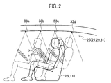
- respective reading lamps 25 to 31 have four light sources 33a to 33d arranged at intervals in the front-back direction so as to sharingly cover the slide ranges of respective seats 7, 9, 11 (namely, ranges of passengers seated thereon) in the front-back direction.
- each of the light sources 33a to 33d includes three LED chips of R, G, and B, and is adapted so as to allow the emission of optional light by adjusting respective brightness of the LED chips.
- double circles in Fig. 2 designate respective eye points P (ranges of moving line of sight) of passengers seated on the seats 7, 9, 11 at respective slide positions of the seats 7, 9, 11 and respective eye ranges L (ranges of moving eye points P due to the differences in passenger's body shape).
- the light sources 33a to 33d of respective reading lamps 25 to 31 are implemented on one circuit substrate 37 (board).
- a connector 35 with a built-in controller (connector with a built-in control unit) is mounted on the circuit substrate 37.
- the connector 35 with the built-in controller includes a female connector part 35 (connector part) with which a male connector 39a of a multiplex communication line 39 can be connected, and a controller 35b (control unit) which is composed of one-chip microcomputer, for example.
- Each of the map lamps 21, 23 includes light sources 33e, 33f each including three LED chips of R, G, and B to allow the emission of optional color.
- the light sources 33e, 33f of each of the map lamps 21, 23 are implemented on another circuit substrate 37.
- a connector 35 with a built-in controller is mounted on this circuit substrate 37, too.
- the light sources 33a to 33d or the light sources 33e, 33f, which are implemented in each circuit substrate 37, are connected to the controller 35b.
- the connection structure of the light sources 33a to 33d with the controller 35b will be described with the connector 35 with the built-in controller on the circuit substrate 37 on which the light sources 33a to 33d of the reading lamps 25 to 31 are implemented, as an example.
- the controller 35b is connected to circuit patterns 37a to 37d of the circuit substrate 37 (see Fig. 4(b) ) through L-shaped terminals 35c extending outwardly through a housing of the connector 35 with the built-in controller.
- the light sources 33a to 33d are connected to the circuit patterns 37a to 37d, respectively.
- the circuit patterns 37a to 37d may be composed by conductive patterns formed on the surface of the circuit substrate 37.
- the circuit substrate 37 composed of a metal-core substrate having a metal plate (core part) as an intermediate layer
- the circuit patterns 37a to 37d may be composed of the metal plate as the intermediate layer.
- a multiplex communication line 39 from a lighting ECU (Electronic Control Unit) 43 (a main control unit) is connected to the controller 35b through the connector part 35a and the male connector 39a.
- the controller 35b controls to turn the light sources 33a to 33d of respective reading lamps 25 to 31 and the light sources 33e, 33f of the map lamps 21, 23 on and off.
- the circuit substrates 37 are arranged on the roof liner 13 of the vehicle 1, and the multiplex communication lines 39 extending from the lighting ECU 43, each of which is connected to the connector 35 with the built-in controller on the circuit substrate 37, are routed inside pillars 15, 17 of the vehicle 1, respectively.
- wires inside the pillars 15, 17 are composed of the multiplex communication lines 39, the number of wires can be reduced in comparison with the arrangement where individual wires to be connected to the respective light sources 33a to 33d are routed inside the pillars 15, 17 and therefore, it is possible to use limited spaces inside the pillars 15, 17 in which many other wires are also routed, effectively.
- vehicle speed data of the vehicle 1 which has been measured by a vehicle speed sensor 47 and transmitted from an engine ECU 45 through an in-vehicle LAN 41, is inputted to the lighting ECU 43 with respect to each constant cycle.
- slide position data of the seats 7, 9, 11 in the front-back direction which has been detected by seat position sensors 51 a to 51 c and transmitted from a seat ECU 49 through the in-vehicle LAN 41, is inputted to the lighting ECU 43 with respect to each constant cycle.
- the slide position data of the seats 7, 9, 11 may be inputted whenever the lighting ECU 43 demands the data for the seat ECU49.
- Inputted from the seat ECU 49 to the lighting ECU 43 through the in-vehicle LAN 41 are seating-condition data about the seats 7, 9 in the second line and the seat 11 (for three passengers) in the third line, which have been detected by seating sensors 53a to 53e and seatbelt fitting-condition data about the seats 7, 9 in the second line and the seat 11 (for three passengers) in the third line, which have been detected by seat belt sensors 55a to 55e.
- Map lamp switches 21a, 23a for turning the map lamps 21, 23 on/off and reading lamp switches 25a to 31 a for turning the reading lamps 25 to 31 on/off are connected to the lighting ECU 43 through an interface (not illustrated).
- the lighting ECU 43 controls to turn the map lamps 21, 23 and the reading lamps 25 to 31 on/off, based on the inputs from the above-mentioned objects to be connected.
- the lighting ECU 43 controls to turn the light sources 33a to 33d of the respective reading lamps 25 to 31 on/off, based on the slide position data of the seats 7, 9, 11 in the front-back direction, which has detected by the seat position sensors 51a to 51c and transmitted from the seat ECU 49, and the ON/OFF states at the reading lamp switches 25a to 31a.
- the lighting ECU 43 includes CPU, RAM, ROM, hard-disc, and the others (all not illustrated). Then, referring to a table stored in the hard-disc and using the RAM as a work area according to the program stored in the ROM, the CPU executes the control of turning the light sources 33a to 33d of the respective reading lumps 25 to 31.
- the second light source 33b from front is turned on with 100% duty.
- the light source 33a in the first front line is turned on with 20% duty
- the rearmost light source 33d is turned off.
- the third light source 33c from front is turned on with 100% duty.
- the second light source 33b from front is turned on with 20% duty, the rearmost light source 33d from front with 50% duty, and the frontmost light source 33a is turned off.
- three LED chips of R, G, B forming the light sources 33a to 33d of the lighting lamps 25 to 31 and the connector 35 with the built-in controller are implemented on the same circuit substrate 37 to abolish the connecting between the controller 35b in the connector 35 with the built-in controller and the respective light sources 33a to 33d through signal lines.
- the controller 35b and the lighting ECU 43 are connected to each other through the multiplex communication line 39, and the multiplex communication lines 39 are routed inside the pillars 15, 17 of the vehicle 1.
- the number of wires can be reduced in comparison with the arrangement where individual wires to be connected to the respective light sources 33a to 33d are routed inside the pillars 15, 17, and therefore, it is possible to use limited spaces inside the pillars 15, 17 in which many other wires are also routed, effectively.
- the load control unit of the present invention is broadly applicable in controlling the driving of a plurality of loads besides the light sources for illumination, based on the control signal inputted to the controller.
- Fig. 7 is an explanatory view illustrating the arrangement of an in-vehicle lighting apparatus to which the load control unit according to a second embodiment of the present invention is applied.
- the vehicle 1 has seats 7, 9 in the second line and a seat 11 in the third line arranged behind a driver's seat 3 and an assistant driver's seat 5 (note: the seat 11 in the third line is one for three passengers).
- the driver's seat 3, the assistant driver's seat 5 and the respective seats 7, 9, 11 behind the former two seats are provided with seat belts 3a, 5a, 7a, 9a, and 11 a to 11c, respectively.
- each of the seat belts 3a, 5a, 7a, 9a, and 11a to 11c is formed by a common three-point seatbelt where a tongue is inserted into a buckle.
- a combination meter 44a in front of the driver's seat 3 and a warning-symbol projector 44b (projection device) on a ceiling part of the vehicle are connected to a meter ECU 43.
- This projector 44b projects, for example, substantially seatbelt-shaped warning symbols WS for prompting the passengers to wear the corresponding seat belts (each as illustrated in Fig. 9(a) ) on respective upper bodies of the passengers seated on the seats 7, 9, 11, as occasion demands.
- the projector 44b may be adapted so as to project, as occasion demands, a warning symbol WS for prompting wearing of the seatbelt on the back face of a backrest of the driver's seat 3 or the assistant driver's seat 7 or the back faces of backrests of the respective seats 7, 9, the back faces being positioned at the front of the passengers who are seated on the seats 7, 9, 11 while being not wearing the seat belts 7a, 9a and 11a to 11c, as illustrated in Fig. 9(b) .
- the vehicle speed data of the vehicle 1 measured by the vehicle speed sensor 47 and engine rotation data measured by an engine sensor 48 are inputted from an engine ECU 45 to the meter ECU 43 through the in-vehicle LAN 41, with respect to each constant cycle.
- the slide position data of the seats 7, 9, 11 in the second and third lines in the front-back direction which has been detected by the seat position sensors 51a to 51c and transmitted from the seat ECU 49 through the in-vehicle LAN 41, is inputted to the meter ECU 43 with respect to each constant cycle.
- the slide position data of the seats 7, 9, 11 may be inputted whenever the meter ECU 43 demands the data for the seat ECU49.
- map lamp switches 21 a, 23a for turning the map lamps 21, 23 on/off and the reading lamp switches 25a to 31 a for turning the reading lamps 25 to 31 on/off are connected to the meter ECU 43 through an interface (not illustrated).
- the meter ECU 43 projects the warning symbol WS for prompting seatbelt wearing (see Figs. 9(a) and 9(b) ) onto a spot where it is easy for the passenger seated on the rear seat to find the symbol, when any passenger seated on the rear seat (the seats 7, 9, or 11) does not wear the seat belt 7a, 9a, 11 a to 11c despite a situation where the seat belts 7a, 9a, and 11a to 11c should be worn.
- the meter ECU 43 includes CPU, RAM, ROM, hard-disc, and the others (all not illustrated). Then, according to the program stored in the ROM and using the RAM as a work area, the CPU executes the control of the projector 44b.
- the CPU judges whether or not the vehicle is in a situation that the seat belts 3a, 5a, 7a, 9a, 11a to 11c should be worn by the passengers (i.e. so-called "seatbelt wearing situation"). This judgment can be carried out by judging whether or not the vehicle speed of the vehicle 1 is 0 (zero) or judging whether or not the engine rotation is 0 (zero).
- step S1 If the vehicle is not in the seatbelt wearing situation (No at step S1), a succession of processes are ended. If the vehicle is in the seatbelt wearing situation (Yes at step S1), it is confirmed whether there is a passenger who does not ware the seat belt 7a, 9a, 11a to 11c on the rear seat (the seat 7, 9, or 11), based on the detection data of the seating sensors 53a to 53e or the seat belt sensors 55a to 55e from the seat ECU 49 (step S3).
- step S3 If there is no passenger who does not wear the seat belt 7a, 9a, 11a to 11c (No at step S3), the projection of the warning symbol WS by the projector 44b is ended (step S5) and thereafter, the succession of processes are ended.
- step S3 if there exists a passenger who does not wear the seat belt 7a, 9a, 11a to 11c (Yes at step S3), it is carried out to project the warning symbol WS illustrated in Fig. 9(a) or 9(b) on either the passenger or the back face of the backrest of a seat 3, 5, 7, 9 in front of the passenger by the projector 44b (step S7) and therefore, the succession of processes are ended.
- the vehicle 1 when the vehicle 1 is in a situation where the seat belts 3a, 5a, 7a, 9a, 11a to 11c should be worn (i.e. the seatbelt wearing situation) and if there is a passenger on the rear seat (the seat 7, 9, 11), who does not wear the seat belt 7a, 9a, 11a to 11c on the rear seat in spite of such a situation, then the warning symbol WS for prompting seatbelt wearing is projected on the upper part of the passenger or the back face of the backrest of a seat (the driver's seat 3, the assistant driver's seat 5, the seas 7, 9 in the second line) in front of the passenger, where it is easy for the passenger on the rear seat (the seat 7, 9, 11) to find the symbol.
- the warning symbol WS for prompting seatbelt wearing is projected on the upper part of the passenger or the back face of the backrest of a seat (the driver's seat 3, the assistant driver's seat 5, the seas 7, 9 in the second line) in front of the passenger, where it is easy
- the passenger who does not wear the related seat belt 7a, 9a, 11a to 11c will recognize that the outputted warning is being directed to oneself.
- the projection of the warning symbol WS may be ended after a given period has passed or once any condition other than the wearing of the seat belt 7a, 9a, 11 a to 11 c is established.
- the present invention is remarkably useful for constructing a load control unit that controls the drive of a plurality of loads based on control signals inputted to a controller.
Landscapes
- Engineering & Computer Science (AREA)
- Mechanical Engineering (AREA)
- Microelectronics & Electronic Packaging (AREA)
- Automation & Control Theory (AREA)
- Arrangements Of Lighting Devices For Vehicle Interiors, Mounting And Supporting Thereof, Circuits Therefore (AREA)
- Lighting Device Outwards From Vehicle And Optical Signal (AREA)
Abstract
Description
- The present invention relates to a load control unit that controls driving of electric loads through a controller.
- A controller is essential for the drive control of loads. In connection, there is a known constitution where a connector having a control unit built in to function a part of the controller is connected to a main control unit through a multiplex communication line, and the connector with the built-in control unit is connected to respective loads through wires for controlling the driving of the respective loads (see PTLs 1-5).
- According to such a conventional constitution, as the built-in control unit of the connector performs the drive control of loads, it is possible to reduce the burden of the main control unit because its role of directly performing the drive control of loads becomes unnecessary. Further, as it has only to connect a wire extending from each load to the connector with the built-in control unit, which is connected to the main control unit through the multiplex communication line, instead of directly connecting respective wires extending from the respective loads to the main control unit individually (in parallel), it is possible to reduce the number of wires to be routed, thereby realizing weight saving of the whole constitution.
-
- PTL 1:
JP 2012-133985 A - PTL 2:
JP 2003-327078 A - PTL 3:
JP 2008-254506 A - PTL 4:
JP 2010-064587 A - PTL 5:
JP 2011-105157 A - In the conventional constitution mentioned above, nevertheless, there still exist wires connecting between the connector and the respective loads individually (in parallel). Therefore, it is necessary to connect the wires extending from all loads with the connector with the built-in control unit, which could be factors for causing a part of the connector with the built-in control unit, into which the wires from the respective loads are inserted, to be increased in size.
- Under the above-mentioned situation, an object of the present invention is to provide a load control unit which is capable of reducing the number of wires as much as possible when constructing a unit where the drive of loads is controlled by a controller.
- In order to attain the above object, according to the first aspect of the present invention, there is provided a load control unit for controlling driving of a plurality of loads based on a control signal inputted from a main control unit into a controller, comprising: the loads implemented on a single substrate; and a connector with a built-in controller, which is mounted on the substrate and to which the respective loads are connected through a circuit pattern of the substrate electrically, the connector having the controller built in, wherein the controller is configured to control the driving of the respective loads based on the control signal which is transmitted from the main control unit and inputted to the controller through a multiplex communication line connected to a connector part of the connector with the built-in controller.
- The loads may be LED chips as light sources for illuminating an interior of a vehicle, and the controller may be configured to control lighting of the LED chips.
- With the load control unit according to the first aspect of the present invention, as the connector with the built-in controller is mounted on the single substrate implementing the plurality of loads so that the controller controls the driving of these loads, the wires connecting the controller and the loads with each other in parallel are made redundant and therefore, a circuit pattern on the substrate takes the place of these wires. Consequently, it is possible to reduce the number of wires as much as possible when constructing a unit where a controller controls driving of a plurality of loads based on a control signal transmitted from a main control unit.
-
-
Fig. 1 is an explanatory view illustrating an arrangement of an in-vehicle illuminating apparatus to which a load control unit according to a first embodiment is applied. -
Fig. 2 is an explanatory view illustrating a relative positional relationship between light sources and vehicle seats illustrated inFig. 1 . -
Fig. 3 is a block diagram illustrating a schematic constitution of a control system for map lamps and reading lamps illustrated inFig. 1 . -
Fig. 4(a) is an explanatory view of a connection relationship between a circuit substrate ofFig. 3 and a lighting ECU or the light sources with respect to a connector with a built-in controller mounted on the circuit substrate in lateral view, andFig. 4(b) is an explanatory view of the same connection relationship in top view. -
Fig. 5 is an explanatory view illustrating the wiring layout between the substrate for reading lamps ofFig. 3 and the lighting ECU. -
Figs. 6(a) and 6(b) are explanatory views illustrating one example of a relationship between a slide position of a seat in the front-back direction, which has been specified on a table stored in a hard-disc of the lighting ECU ofFig. 3 , and the lighting pattern of the light sources. -
Fig. 7 is an explanatory view illustrating an arrangement of an in-vehicle illuminating apparatus to which a load control unit according to a second embodiment is applied. -
Fig. 8 is a block diagram illustrating an electrical constitution for supporting the use of seat belts illustrated inFig. 7 . -
Figs. 9(a) and 9(b) are explanatory views illustrating projected images by a projector ofFig. 8 . -
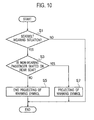
Fig. 10 is a flow chart illustrating the process of controlling the projective displaying of a warning symbol for promoting the use of rear seat belts, which is executed according to a program stored in ROM by a meter ECU ofFig. 8 . - Embodiments of the present invention will be described with reference to drawings, below.
-
Fig. 1 is an explanatory view illustrating the arrangement of lighting modules to which a load control unit according to a first embodiment of the present invention is applied. - In a vehicle 1, as illustrated in
Fig. 1 ,map lamps 21, 23 respectively corresponding to a driver'sseat 3 and an assistant driver'sseat 5 are arranged at a frontal center of a roof liner 13 (seeFig. 5 ) in the vehicle. Further, the vehicle 1 is provided, on left and right sides of theroof liner 13, withreading lamps 25 to 31 corresponding toseats seat 11 in the third line (note: as for theseat 11 in the third line, the reading lamps are arranged so as to correspond to both ends of the "triple" seat). Then, a lighting module according to the first embodiment is applied to thereading lamps 25 to 31 and their lighting control system. - As illustrated in the explanatory view of
Fig. 2 ,respective reading lamps 25 to 31 have fourlight sources 33a to 33d arranged at intervals in the front-back direction so as to sharingly cover the slide ranges ofrespective seats light sources 33a to 33d includes three LED chips of R, G, and B, and is adapted so as to allow the emission of optional light by adjusting respective brightness of the LED chips. - In connection, double circles in
Fig. 2 designate respective eye points P (ranges of moving line of sight) of passengers seated on theseats seats - Next, the schematic constitution of a control system of the
reading lamps 25 to 31 and themap lamps 21, 23 will be described with reference to a block diagram ofFig. 3 . In the first embodiment, thelight sources 33a to 33d ofrespective reading lamps 25 to 31 are implemented on one circuit substrate 37 (board). Aconnector 35 with a built-in controller (connector with a built-in control unit) is mounted on thecircuit substrate 37. Theconnector 35 with the built-in controller includes a female connector part 35 (connector part) with which amale connector 39a of amultiplex communication line 39 can be connected, and acontroller 35b (control unit) which is composed of one-chip microcomputer, for example. - Each of the
map lamps 21, 23 includeslight sources light sources map lamps 21, 23 are implemented on anothercircuit substrate 37. Aconnector 35 with a built-in controller is mounted on thiscircuit substrate 37, too. - The
light sources 33a to 33d or thelight sources circuit substrate 37, are connected to thecontroller 35b. - Here, the connection structure of the
light sources 33a to 33d with thecontroller 35b will be described with theconnector 35 with the built-in controller on thecircuit substrate 37 on which thelight sources 33a to 33d of thereading lamps 25 to 31 are implemented, as an example. As illustrated inFigs. 4(a) and 4(b) , thecontroller 35b is connected tocircuit patterns 37a to 37d of the circuit substrate 37 (seeFig. 4(b) ) through L-shaped terminals 35c extending outwardly through a housing of theconnector 35 with the built-in controller. Thelight sources 33a to 33d are connected to thecircuit patterns 37a to 37d, respectively. - Note, the
circuit patterns 37a to 37d may be composed by conductive patterns formed on the surface of thecircuit substrate 37. In case of thecircuit substrate 37 composed of a metal-core substrate having a metal plate (core part) as an intermediate layer, alternatively, thecircuit patterns 37a to 37d may be composed of the metal plate as the intermediate layer. - Further, a
multiplex communication line 39 from a lighting ECU (Electronic Control Unit) 43 (a main control unit) is connected to thecontroller 35b through theconnector part 35a and themale connector 39a. - Based on control signals inputted from the
lighting ECU 43 through themultiplex communication line 39, therefore, thecontroller 35b controls to turn thelight sources 33a to 33d ofrespective reading lamps 25 to 31 and thelight sources map lamps 21, 23 on and off. - As illustrated with the explanatory view of
Fig. 5 , thecircuit substrates 37 are arranged on theroof liner 13 of the vehicle 1, and themultiplex communication lines 39 extending from thelighting ECU 43, each of which is connected to theconnector 35 with the built-in controller on thecircuit substrate 37, are routed insidepillars - Since wires inside the
pillars multiplex communication lines 39, the number of wires can be reduced in comparison with the arrangement where individual wires to be connected to therespective light sources 33a to 33d are routed inside thepillars pillars - As illustrated in
Fig. 3 , vehicle speed data of the vehicle 1, which has been measured by avehicle speed sensor 47 and transmitted from anengine ECU 45 through an in-vehicle LAN 41, is inputted to thelighting ECU 43 with respect to each constant cycle. Also, slide position data of theseats seat position sensors 51 a to 51 c and transmitted from aseat ECU 49 through the in-vehicle LAN 41, is inputted to thelighting ECU 43 with respect to each constant cycle. The slide position data of theseats lighting ECU 43 demands the data for the seat ECU49. - Inputted from the
seat ECU 49 to thelighting ECU 43 through the in-vehicle LAN 41 are seating-condition data about theseats seating sensors 53a to 53e and seatbelt fitting-condition data about theseats seat belt sensors 55a to 55e. -
Map lamp switches map lamps 21, 23 on/off and readinglamp switches 25a to 31 a for turning thereading lamps 25 to 31 on/off are connected to thelighting ECU 43 through an interface (not illustrated). - Then, the
lighting ECU 43 controls to turn themap lamps 21, 23 and thereading lamps 25 to 31 on/off, based on the inputs from the above-mentioned objects to be connected. In the first embodiment, especially, thelighting ECU 43 controls to turn thelight sources 33a to 33d of therespective reading lamps 25 to 31 on/off, based on the slide position data of theseats seat position sensors 51a to 51c and transmitted from theseat ECU 49, and the ON/OFF states at thereading lamp switches 25a to 31a. - To this end, the
lighting ECU 43 includes CPU, RAM, ROM, hard-disc, and the others (all not illustrated). Then, referring to a table stored in the hard-disc and using the RAM as a work area according to the program stored in the ROM, the CPU executes the control of turning thelight sources 33a to 33d of the respective reading lumps 25 to 31. - In the table stored in the hard-disc, there are defined the slid positions of the
seats light sources 33a to 33d (including brightness = luminance) and their lights-out patterns. - For instance, as illustrated with the explanatory view of
Fig. 6(a) , in the lighting pattern when the seat 7 (9, 11) is in a substantially intermediate slide position in the front-back direction, the secondlight source 33b from front is turned on with 100% duty. Also, thelight source 33a in the first front line is turned on with 20% duty, the thirdlight source 33c from front with 50% duty, and the rearmostlight source 33d is turned off. - Additionally, as illustrated with the explanatory view of
Fig. 6(b) , in the lighting pattern when the seat 7 (9, 11) is in a substantially intermediate slide position in the front-back direction, the thirdlight source 33c from front is turned on with 100% duty. Also, the secondlight source 33b from front is turned on with 20% duty, the rearmostlight source 33d from front with 50% duty, and the frontmostlight source 33a is turned off. - As mentioned above, according to the first embodiment, three LED chips of R, G, B forming the
light sources 33a to 33d of thelighting lamps 25 to 31 and theconnector 35 with the built-in controller are implemented on thesame circuit substrate 37 to abolish the connecting between thecontroller 35b in theconnector 35 with the built-in controller and therespective light sources 33a to 33d through signal lines. Simultaneously, thecontroller 35b and thelighting ECU 43 are connected to each other through themultiplex communication line 39, and themultiplex communication lines 39 are routed inside thepillars - Consequently, the number of wires can be reduced in comparison with the arrangement where individual wires to be connected to the
respective light sources 33a to 33d are routed inside thepillars pillars - Although the first embodiment is directed to the application of the load control unit of the present invention to the lighting module for illuminating the interior of a vehicle, the load control unit of the present invention is broadly applicable in controlling the driving of a plurality of loads besides the light sources for illumination, based on the control signal inputted to the controller.
-
Fig. 7 is an explanatory view illustrating the arrangement of an in-vehicle lighting apparatus to which the load control unit according to a second embodiment of the present invention is applied. - As illustrated in
Fig. 7 , the vehicle 1 hasseats seat 11 in the third line arranged behind a driver'sseat 3 and an assistant driver's seat 5 (note: theseat 11 in the third line is one for three passengers). The driver'sseat 3, the assistant driver'sseat 5 and therespective seats seat belts seat belts - Next, the electrical constitution for supporting the wearing of the
seat belts seats seat 3 and the assistant driver'sseat 5 will be described with reference to a block diagram ofFig. 8 . - According to the second embodiment, as illustrated in
Fig. 8 , acombination meter 44a in front of the driver'sseat 3 and a warning-symbol projector 44b (projection device) on a ceiling part of the vehicle are connected to ameter ECU 43. Thisprojector 44b projects, for example, substantially seatbelt-shaped warning symbols WS for prompting the passengers to wear the corresponding seat belts (each as illustrated inFig. 9(a) ) on respective upper bodies of the passengers seated on theseats - In connection, the
projector 44b may be adapted so as to project, as occasion demands, a warning symbol WS for prompting wearing of the seatbelt on the back face of a backrest of the driver'sseat 3 or the assistant driver'sseat 7 or the back faces of backrests of therespective seats seats seat belts Fig. 9(b) . - In
Fig. 8 , the vehicle speed data of the vehicle 1 measured by thevehicle speed sensor 47 and engine rotation data measured by an engine sensor 48 are inputted from anengine ECU 45 to themeter ECU 43 through the in-vehicle LAN 41, with respect to each constant cycle. Also, the slide position data of theseats seat position sensors 51a to 51c and transmitted from theseat ECU 49 through the in-vehicle LAN 41, is inputted to themeter ECU 43 with respect to each constant cycle. The slide position data of theseats meter ECU 43 demands the data for the seat ECU49. - Further inputted from the
seat ECU 49 to themeter ECU 43 through the in-vehicle LAN 41 are the seating-condition data about theseats seating sensors 53a to 53e, and the seatbelt fitting-condition data about theseats seat belt sensors 55a to 55e. - Also, the map lamp switches 21 a, 23a for turning the
map lamps 21, 23 on/off and thereading lamp switches 25a to 31 a for turning the readinglamps 25 to 31 on/off are connected to themeter ECU 43 through an interface (not illustrated). - Based on the inputs from the above-mentioned objects to be connected, the
meter ECU 43 projects the warning symbol WS for prompting seatbelt wearing (seeFigs. 9(a) and 9(b) ) onto a spot where it is easy for the passenger seated on the rear seat to find the symbol, when any passenger seated on the rear seat (theseats seat belt seat belts - To this end, the
meter ECU 43 includes CPU, RAM, ROM, hard-disc, and the others (all not illustrated). Then, according to the program stored in the ROM and using the RAM as a work area, the CPU executes the control of theprojector 44b. - Next, the process of projective display control of the warning symbol WS for prompting seatbelt wearing against the passengers seated on the
seats meter ECU 43 of the second embodiment executes according to the program stored in the ROM, will be described with reference to a flow chart ofFig. 10 . The CPU executes the control of processes illustrated inFig. 10 with respect to each predetermined cycle repeatedly. - First, the CPU judges whether or not the vehicle is in a situation that the
seat belts - If the vehicle is not in the seatbelt wearing situation (No at step S1), a succession of processes are ended. If the vehicle is in the seatbelt wearing situation (Yes at step S1), it is confirmed whether there is a passenger who does not ware the
seat belt seat seating sensors 53a to 53e or theseat belt sensors 55a to 55e from the seat ECU 49 (step S3). - If there is no passenger who does not wear the
seat belt projector 44b is ended (step S5) and thereafter, the succession of processes are ended. On the other hand, if there exists a passenger who does not wear theseat belt Fig. 9(a) or 9(b) on either the passenger or the back face of the backrest of aseat projector 44b (step S7) and therefore, the succession of processes are ended. - As described above, according to the second embodiment, when the vehicle 1 is in a situation where the
seat belts seat seat belt seat 3, the assistant driver'sseat 5, theseas seat - For this reason, the passenger who does not wear the
related seat belt seat - In connection, the projection of the warning symbol WS may be ended after a given period has passed or once any condition other than the wearing of the
seat belt - The present invention is remarkably useful for constructing a load control unit that controls the drive of a plurality of loads based on control signals inputted to a controller.
Claims (2)
- A load control unit for controlling driving of a plurality of loads based on a control signal inputted from a main control unit into a controller, comprising:the loads implemented on a single substrate; anda connector with a built-in controller, which is mounted on the substrate and to which the respective loads are connected through a circuit pattern of the substrate electrically, the connector having the controller built in, whereinthe controller is configured to control the driving of the respective loads based on the control signal which is transmitted from the main control unit and inputted to the controller through a multiplex communication line connected to a connector part of the connector with the built-in controller.
- The load control unit according to claim 1, wherein
the loads are LED chips as light sources for illuminating an interior of a vehicle, and
the controller is configured to control lighting of the LED chips.
Applications Claiming Priority (4)
| Application Number | Priority Date | Filing Date | Title |
|---|---|---|---|
| JP2012222426A JP6080470B2 (en) | 2012-10-04 | 2012-10-04 | Load control unit |
| JP2012222424A JP6080469B2 (en) | 2012-10-04 | 2012-10-04 | Lighting module |
| JP2012222428A JP6039988B2 (en) | 2012-10-04 | 2012-10-04 | Rear seat belt belt support device |
| PCT/JP2013/076700 WO2014054637A1 (en) | 2012-10-04 | 2013-10-01 | Load control unit |
Publications (3)
| Publication Number | Publication Date |
|---|---|
| EP2905173A1 true EP2905173A1 (en) | 2015-08-12 |
| EP2905173A4 EP2905173A4 (en) | 2016-06-29 |
| EP2905173B1 EP2905173B1 (en) | 2021-08-25 |
Family
ID=50434963
Family Applications (1)
| Application Number | Title | Priority Date | Filing Date |
|---|---|---|---|
| EP13843513.6A Active EP2905173B1 (en) | 2012-10-04 | 2013-10-01 | Lighting system for illuminating the interior of a vehicle having sliding seats |
Country Status (4)
| Country | Link |
|---|---|
| US (1) | US9565743B2 (en) |
| EP (1) | EP2905173B1 (en) |
| CN (1) | CN104703841A (en) |
| WO (1) | WO2014054637A1 (en) |
Cited By (2)
| Publication number | Priority date | Publication date | Assignee | Title |
|---|---|---|---|---|
| WO2017062691A1 (en) * | 2015-10-06 | 2017-04-13 | Pacific Insight Electronics Corp. | Smart lighting system for a vehicle |
| WO2019166086A1 (en) * | 2018-02-28 | 2019-09-06 | Toyota Motor Europe | System and method for checking the rear seat belt status in a vehicle |
Families Citing this family (5)
| Publication number | Priority date | Publication date | Assignee | Title |
|---|---|---|---|---|
| JP6422921B2 (en) * | 2016-08-12 | 2018-11-14 | 矢崎総業株式会社 | In-vehicle device control system |
| US10416671B2 (en) | 2017-07-11 | 2019-09-17 | Waymo Llc | Methods and systems for vehicle occupancy confirmation |
| CN108322964B (en) * | 2018-04-03 | 2023-09-08 | 深圳茂硕电子科技有限公司 | LED driving power circuit |
| CN111347841B (en) * | 2020-03-23 | 2022-05-13 | 高斯贝尔数码科技股份有限公司 | Automobile disinfection lamp control system and method |
| US11739905B1 (en) * | 2022-06-21 | 2023-08-29 | Ford Global Technologies, Llc | Light assembly providing pillar lamp for motor vehicle |
Family Cites Families (33)
| Publication number | Priority date | Publication date | Assignee | Title |
|---|---|---|---|---|
| JPH05129051A (en) | 1991-10-31 | 1993-05-25 | Rohm Co Ltd | Ic's built-in connector |
| JPH0795658A (en) * | 1993-09-24 | 1995-04-07 | Nippondenso Co Ltd | Communication connector |
| JPH09290682A (en) | 1996-04-26 | 1997-11-11 | Harness Sogo Kijiyutsu Kenkyusho:Kk | Lamp control circuit for automobile |
| US5798575A (en) * | 1996-07-11 | 1998-08-25 | Donnelly Corporation | Vehicle mirror digital network and dynamically interactive mirror system |
| US6097283A (en) | 1998-04-01 | 2000-08-01 | Lear Automotive Dearborn, Inc. | Rear lamp module with trailer tow connector |
| JP2003063392A (en) | 2001-08-28 | 2003-03-05 | Fujikura Ltd | Passenger detection system |
| JP3881929B2 (en) | 2002-05-15 | 2007-02-14 | 矢崎総業株式会社 | Seat belt reminder method and seat belt reminder device |
| US8410945B2 (en) * | 2002-06-11 | 2013-04-02 | Intelligent Technologies International, Inc | Atmospheric monitoring |
| JP2004259582A (en) | 2003-02-26 | 2004-09-16 | Yazaki Corp | Lamp control circuit and lamp control method |
| JP4139261B2 (en) | 2003-04-09 | 2008-08-27 | 矢崎総業株式会社 | Front electrical system, electronic control unit and electrical connector for front electrical system |
| US7106005B2 (en) * | 2003-11-18 | 2006-09-12 | Nissan Motor Co., Ltd. | Vehicle room lamp control device and vehicle room lamp control method |
| JP2006062594A (en) * | 2004-08-30 | 2006-03-09 | Yazaki Corp | Car interior lamp control system |
| DE102004043197A1 (en) * | 2004-09-03 | 2006-03-09 | Lehmann, Erhard, Dipl.-Ing. (FH) | Control process for a lighting unit with many light modules has control units and central control transmitting a control data stream that can be changed individually |
| DE102004060890A1 (en) * | 2004-12-17 | 2006-06-29 | Patent-Treuhand-Gesellschaft für elektrische Glühlampen mbH | Motor vehicle headlight element |
| JP2007253807A (en) | 2006-03-23 | 2007-10-04 | Mitsubishi Electric Corp | Automatic display angle adjustment device |
| JP4487968B2 (en) * | 2006-04-07 | 2010-06-23 | 豊田合成株式会社 | In-vehicle LED lighting system |
| US7800483B2 (en) * | 2006-11-10 | 2010-09-21 | Federal-Mogul World Wide, Inc. | Transitional lighting system for vehicle interior |
| JP2008143457A (en) | 2006-12-13 | 2008-06-26 | Mazda Motor Corp | Vehicle seat belt control device |
| JP4930315B2 (en) | 2007-01-19 | 2012-05-16 | 株式会社デンソー | In-vehicle information display device and light irradiation device used therefor |
| US7540641B2 (en) * | 2007-02-08 | 2009-06-02 | Ford Global Technologies, Llc | Apparatus and method for dimming function to control LED intensity |
| JP5173229B2 (en) | 2007-04-02 | 2013-04-03 | トヨタ自動車株式会社 | Seat belt wearing system, seat belt wearing promotion method |
| US8400061B2 (en) * | 2007-07-17 | 2013-03-19 | I/O Controls Corporation | Control network for LED-based lighting system in a transit vehicle |
| JP5225744B2 (en) | 2008-05-08 | 2013-07-03 | 林テレンプ株式会社 | LIGHTING DEVICE FOR AUTOMOBILE, LIGHT GUIDE AND MANUFACTURING METHOD THEREOF |
| DE102008033733B4 (en) | 2008-07-17 | 2020-06-18 | Airbus Operations Gmbh | System and method for operating a variety of service positions |
| US20100052536A1 (en) * | 2008-09-04 | 2010-03-04 | Ford Global Technologies, Llc | Ambient led lighting system and method |
| JP2010064587A (en) | 2008-09-10 | 2010-03-25 | Mitsubishi Electric Corp | Display device and display system |
| US8604922B2 (en) * | 2009-06-25 | 2013-12-10 | Glen Harris | Programmable taillight illumination system |
| JP2011020538A (en) | 2009-07-15 | 2011-02-03 | Panasonic Corp | Seatback display angle control device |
| FR2949403B1 (en) | 2009-08-25 | 2011-08-05 | Peugeot Citroen Automobiles Sa | VIDEO PROJECTION DEVICE FOR VEHICLE AND CORRESPONDING CONTROL DEVICE |
| JP2011105157A (en) | 2009-11-18 | 2011-06-02 | Kojima Press Industry Co Ltd | Seat belt wearing warning device |
| EP2512920B1 (en) | 2009-12-15 | 2019-01-30 | Airbus Operations GmbH | Supply module for passenger transport vehicles |
| JP5705528B2 (en) | 2010-12-21 | 2015-04-22 | 矢崎総業株式会社 | Wire harness structure and lighting unit |
| JP2016055838A (en) | 2014-09-12 | 2016-04-21 | 矢崎総業株式会社 | Interior lighting device |
-
2013
- 2013-10-01 WO PCT/JP2013/076700 patent/WO2014054637A1/en not_active Ceased
- 2013-10-01 CN CN201380051614.6A patent/CN104703841A/en active Pending
- 2013-10-01 EP EP13843513.6A patent/EP2905173B1/en active Active
- 2013-10-01 US US14/432,761 patent/US9565743B2/en active Active
Cited By (3)
| Publication number | Priority date | Publication date | Assignee | Title |
|---|---|---|---|---|
| WO2017062691A1 (en) * | 2015-10-06 | 2017-04-13 | Pacific Insight Electronics Corp. | Smart lighting system for a vehicle |
| WO2019166086A1 (en) * | 2018-02-28 | 2019-09-06 | Toyota Motor Europe | System and method for checking the rear seat belt status in a vehicle |
| US11167722B2 (en) | 2018-02-28 | 2021-11-09 | Toyota Motor Europe | System and method for checking the rear seat belt status in a vehicle |
Also Published As
| Publication number | Publication date |
|---|---|
| US20150282280A1 (en) | 2015-10-01 |
| EP2905173A4 (en) | 2016-06-29 |
| CN104703841A (en) | 2015-06-10 |
| WO2014054637A1 (en) | 2014-04-10 |
| EP2905173B1 (en) | 2021-08-25 |
| US9565743B2 (en) | 2017-02-07 |
Similar Documents
| Publication | Publication Date | Title |
|---|---|---|
| US9565743B2 (en) | Load control unit | |
| EP2905175A1 (en) | Vehicle-interior illumination device | |
| JP5705528B2 (en) | Wire harness structure and lighting unit | |
| US10471912B2 (en) | In-vehicle equipment control system | |
| JP6389158B2 (en) | Wire harness for vehicles | |
| US10549718B2 (en) | Vehicle warning device | |
| US20190001891A1 (en) | Vehicle roof mounted system | |
| US20200130575A1 (en) | In-cabin lighting device | |
| US9789962B2 (en) | Passenger service module with integrated cabin lighting | |
| JP2014065381A (en) | Seat belt device | |
| JP4697198B2 (en) | Vehicle display device | |
| CN105828471B (en) | Illuminator in vehicle interior | |
| KR101834733B1 (en) | Camera system for a vehicle | |
| JP6080470B2 (en) | Load control unit | |
| CN107074151A (en) | Electronic circuit for blind spot monitoring display device | |
| JP6080469B2 (en) | Lighting module | |
| JP6523704B2 (en) | In-vehicle condition confirmation device | |
| CN205909135U (en) | Tail lamp and vehicle | |
| US20260138530A1 (en) | Vehicular lamp system, and configurating device and configurating method for vehicular lamp | |
| KR20160104989A (en) | Vehicle taillights | |
| JP2016155402A (en) | Demonstration operation device of vehicular electric component | |
| JP2010039268A (en) | Display device |
Legal Events
| Date | Code | Title | Description |
|---|---|---|---|
| PUAI | Public reference made under article 153(3) epc to a published international application that has entered the european phase |
Free format text: ORIGINAL CODE: 0009012 |
|
| 17P | Request for examination filed |
Effective date: 20150422 |
|
| AK | Designated contracting states |
Kind code of ref document: A1 Designated state(s): AL AT BE BG CH CY CZ DE DK EE ES FI FR GB GR HR HU IE IS IT LI LT LU LV MC MK MT NL NO PL PT RO RS SE SI SK SM TR |
|
| AX | Request for extension of the european patent |
Extension state: BA ME |
|
| DAX | Request for extension of the european patent (deleted) | ||
| RA4 | Supplementary search report drawn up and despatched (corrected) |
Effective date: 20160601 |
|
| RIC1 | Information provided on ipc code assigned before grant |
Ipc: H01R 12/72 20110101ALI20160525BHEP Ipc: H05B 33/08 20060101ALI20160525BHEP Ipc: H05B 37/02 20060101ALI20160525BHEP Ipc: H01R 13/66 20060101ALI20160525BHEP Ipc: F21V 23/00 20150101ALI20160525BHEP Ipc: B60R 22/48 20060101ALI20160525BHEP Ipc: F21V 23/06 20060101ALI20160525BHEP Ipc: B60Q 3/02 20060101AFI20160525BHEP Ipc: B60R 16/02 20060101ALI20160525BHEP |
|
| STAA | Information on the status of an ep patent application or granted ep patent |
Free format text: STATUS: EXAMINATION IS IN PROGRESS |
|
| 17Q | First examination report despatched |
Effective date: 20200220 |
|
| REG | Reference to a national code |
Ref country code: DE Ref legal event code: R079 Ref document number: 602013078993 Country of ref document: DE Free format text: PREVIOUS MAIN CLASS: B60Q0003020000 Ipc: B60R0016020000 |
|
| RIC1 | Information provided on ipc code assigned before grant |
Ipc: B60Q 3/233 20170101ALI20210128BHEP Ipc: F21V 23/06 20060101ALI20210128BHEP Ipc: H05B 33/08 20200101ALI20210128BHEP Ipc: H01R 13/66 20060101ALI20210128BHEP Ipc: H05B 45/20 20200101ALI20210128BHEP Ipc: H05B 47/18 20200101ALI20210128BHEP Ipc: B60Q 3/80 20170101ALI20210128BHEP Ipc: B60Q 3/76 20170101ALI20210128BHEP Ipc: H01R 12/72 20110101ALI20210128BHEP Ipc: F21V 23/00 20150101ALI20210128BHEP Ipc: B60R 16/02 20060101AFI20210128BHEP Ipc: B60R 22/48 20060101ALI20210128BHEP |
|
| GRAP | Despatch of communication of intention to grant a patent |
Free format text: ORIGINAL CODE: EPIDOSNIGR1 |
|
| STAA | Information on the status of an ep patent application or granted ep patent |
Free format text: STATUS: GRANT OF PATENT IS INTENDED |
|
| INTG | Intention to grant announced |
Effective date: 20210409 |
|
| GRAS | Grant fee paid |
Free format text: ORIGINAL CODE: EPIDOSNIGR3 |
|
| GRAA | (expected) grant |
Free format text: ORIGINAL CODE: 0009210 |
|
| STAA | Information on the status of an ep patent application or granted ep patent |
Free format text: STATUS: THE PATENT HAS BEEN GRANTED |
|
| AK | Designated contracting states |
Kind code of ref document: B1 Designated state(s): AL AT BE BG CH CY CZ DE DK EE ES FI FR GB GR HR HU IE IS IT LI LT LU LV MC MK MT NL NO PL PT RO RS SE SI SK SM TR |
|
| REG | Reference to a national code |
Ref country code: GB Ref legal event code: FG4D |
|
| REG | Reference to a national code |
Ref country code: CH Ref legal event code: EP |
|
| REG | Reference to a national code |
Ref country code: DE Ref legal event code: R096 Ref document number: 602013078993 Country of ref document: DE |
|
| REG | Reference to a national code |
Ref country code: IE Ref legal event code: FG4D Ref country code: AT Ref legal event code: REF Ref document number: 1423481 Country of ref document: AT Kind code of ref document: T Effective date: 20210915 |
|
| REG | Reference to a national code |
Ref country code: LT Ref legal event code: MG9D |
|
| REG | Reference to a national code |
Ref country code: NL Ref legal event code: MP Effective date: 20210825 |
|
| REG | Reference to a national code |
Ref country code: AT Ref legal event code: MK05 Ref document number: 1423481 Country of ref document: AT Kind code of ref document: T Effective date: 20210825 |
|
| PG25 | Lapsed in a contracting state [announced via postgrant information from national office to epo] |
Ref country code: HR Free format text: LAPSE BECAUSE OF FAILURE TO SUBMIT A TRANSLATION OF THE DESCRIPTION OR TO PAY THE FEE WITHIN THE PRESCRIBED TIME-LIMIT Effective date: 20210825 Ref country code: RS Free format text: LAPSE BECAUSE OF FAILURE TO SUBMIT A TRANSLATION OF THE DESCRIPTION OR TO PAY THE FEE WITHIN THE PRESCRIBED TIME-LIMIT Effective date: 20210825 Ref country code: SE Free format text: LAPSE BECAUSE OF FAILURE TO SUBMIT A TRANSLATION OF THE DESCRIPTION OR TO PAY THE FEE WITHIN THE PRESCRIBED TIME-LIMIT Effective date: 20210825 Ref country code: LT Free format text: LAPSE BECAUSE OF FAILURE TO SUBMIT A TRANSLATION OF THE DESCRIPTION OR TO PAY THE FEE WITHIN THE PRESCRIBED TIME-LIMIT Effective date: 20210825 Ref country code: BG Free format text: LAPSE BECAUSE OF FAILURE TO SUBMIT A TRANSLATION OF THE DESCRIPTION OR TO PAY THE FEE WITHIN THE PRESCRIBED TIME-LIMIT Effective date: 20211125 Ref country code: AT Free format text: LAPSE BECAUSE OF FAILURE TO SUBMIT A TRANSLATION OF THE DESCRIPTION OR TO PAY THE FEE WITHIN THE PRESCRIBED TIME-LIMIT Effective date: 20210825 Ref country code: PT Free format text: LAPSE BECAUSE OF FAILURE TO SUBMIT A TRANSLATION OF THE DESCRIPTION OR TO PAY THE FEE WITHIN THE PRESCRIBED TIME-LIMIT Effective date: 20211227 Ref country code: NO Free format text: LAPSE BECAUSE OF FAILURE TO SUBMIT A TRANSLATION OF THE DESCRIPTION OR TO PAY THE FEE WITHIN THE PRESCRIBED TIME-LIMIT Effective date: 20211125 Ref country code: ES Free format text: LAPSE BECAUSE OF FAILURE TO SUBMIT A TRANSLATION OF THE DESCRIPTION OR TO PAY THE FEE WITHIN THE PRESCRIBED TIME-LIMIT Effective date: 20210825 Ref country code: FI Free format text: LAPSE BECAUSE OF FAILURE TO SUBMIT A TRANSLATION OF THE DESCRIPTION OR TO PAY THE FEE WITHIN THE PRESCRIBED TIME-LIMIT Effective date: 20210825 |
|
| PG25 | Lapsed in a contracting state [announced via postgrant information from national office to epo] |
Ref country code: PL Free format text: LAPSE BECAUSE OF FAILURE TO SUBMIT A TRANSLATION OF THE DESCRIPTION OR TO PAY THE FEE WITHIN THE PRESCRIBED TIME-LIMIT Effective date: 20210825 Ref country code: LV Free format text: LAPSE BECAUSE OF FAILURE TO SUBMIT A TRANSLATION OF THE DESCRIPTION OR TO PAY THE FEE WITHIN THE PRESCRIBED TIME-LIMIT Effective date: 20210825 Ref country code: GR Free format text: LAPSE BECAUSE OF FAILURE TO SUBMIT A TRANSLATION OF THE DESCRIPTION OR TO PAY THE FEE WITHIN THE PRESCRIBED TIME-LIMIT Effective date: 20211126 |
|
| PG25 | Lapsed in a contracting state [announced via postgrant information from national office to epo] |
Ref country code: NL Free format text: LAPSE BECAUSE OF FAILURE TO SUBMIT A TRANSLATION OF THE DESCRIPTION OR TO PAY THE FEE WITHIN THE PRESCRIBED TIME-LIMIT Effective date: 20210825 |
|
| PG25 | Lapsed in a contracting state [announced via postgrant information from national office to epo] |
Ref country code: DK Free format text: LAPSE BECAUSE OF FAILURE TO SUBMIT A TRANSLATION OF THE DESCRIPTION OR TO PAY THE FEE WITHIN THE PRESCRIBED TIME-LIMIT Effective date: 20210825 |
|
| REG | Reference to a national code |
Ref country code: DE Ref legal event code: R097 Ref document number: 602013078993 Country of ref document: DE |
|
| PG25 | Lapsed in a contracting state [announced via postgrant information from national office to epo] |
Ref country code: SM Free format text: LAPSE BECAUSE OF FAILURE TO SUBMIT A TRANSLATION OF THE DESCRIPTION OR TO PAY THE FEE WITHIN THE PRESCRIBED TIME-LIMIT Effective date: 20210825 Ref country code: SK Free format text: LAPSE BECAUSE OF FAILURE TO SUBMIT A TRANSLATION OF THE DESCRIPTION OR TO PAY THE FEE WITHIN THE PRESCRIBED TIME-LIMIT Effective date: 20210825 Ref country code: RO Free format text: LAPSE BECAUSE OF FAILURE TO SUBMIT A TRANSLATION OF THE DESCRIPTION OR TO PAY THE FEE WITHIN THE PRESCRIBED TIME-LIMIT Effective date: 20210825 Ref country code: EE Free format text: LAPSE BECAUSE OF FAILURE TO SUBMIT A TRANSLATION OF THE DESCRIPTION OR TO PAY THE FEE WITHIN THE PRESCRIBED TIME-LIMIT Effective date: 20210825 Ref country code: CZ Free format text: LAPSE BECAUSE OF FAILURE TO SUBMIT A TRANSLATION OF THE DESCRIPTION OR TO PAY THE FEE WITHIN THE PRESCRIBED TIME-LIMIT Effective date: 20210825 Ref country code: AL Free format text: LAPSE BECAUSE OF FAILURE TO SUBMIT A TRANSLATION OF THE DESCRIPTION OR TO PAY THE FEE WITHIN THE PRESCRIBED TIME-LIMIT Effective date: 20210825 |
|
| REG | Reference to a national code |
Ref country code: CH Ref legal event code: PL |
|
| REG | Reference to a national code |
Ref country code: BE Ref legal event code: MM Effective date: 20211031 |
|
| PG25 | Lapsed in a contracting state [announced via postgrant information from national office to epo] |
Ref country code: MC Free format text: LAPSE BECAUSE OF FAILURE TO SUBMIT A TRANSLATION OF THE DESCRIPTION OR TO PAY THE FEE WITHIN THE PRESCRIBED TIME-LIMIT Effective date: 20210825 |
|
| PLBE | No opposition filed within time limit |
Free format text: ORIGINAL CODE: 0009261 |
|
| STAA | Information on the status of an ep patent application or granted ep patent |
Free format text: STATUS: NO OPPOSITION FILED WITHIN TIME LIMIT |
|
| GBPC | Gb: european patent ceased through non-payment of renewal fee |
Effective date: 20211125 |
|
| PG25 | Lapsed in a contracting state [announced via postgrant information from national office to epo] |
Ref country code: LU Free format text: LAPSE BECAUSE OF NON-PAYMENT OF DUE FEES Effective date: 20211001 Ref country code: BE Free format text: LAPSE BECAUSE OF NON-PAYMENT OF DUE FEES Effective date: 20211031 |
|
| 26N | No opposition filed |
Effective date: 20220527 |
|
| PG25 | Lapsed in a contracting state [announced via postgrant information from national office to epo] |
Ref country code: SI Free format text: LAPSE BECAUSE OF FAILURE TO SUBMIT A TRANSLATION OF THE DESCRIPTION OR TO PAY THE FEE WITHIN THE PRESCRIBED TIME-LIMIT Effective date: 20210825 Ref country code: LI Free format text: LAPSE BECAUSE OF NON-PAYMENT OF DUE FEES Effective date: 20211031 Ref country code: CH Free format text: LAPSE BECAUSE OF NON-PAYMENT OF DUE FEES Effective date: 20211031 |
|
| PG25 | Lapsed in a contracting state [announced via postgrant information from national office to epo] |
Ref country code: IE Free format text: LAPSE BECAUSE OF NON-PAYMENT OF DUE FEES Effective date: 20211001 Ref country code: GB Free format text: LAPSE BECAUSE OF NON-PAYMENT OF DUE FEES Effective date: 20211125 |
|
| PG25 | Lapsed in a contracting state [announced via postgrant information from national office to epo] |
Ref country code: HU Free format text: LAPSE BECAUSE OF FAILURE TO SUBMIT A TRANSLATION OF THE DESCRIPTION OR TO PAY THE FEE WITHIN THE PRESCRIBED TIME-LIMIT; INVALID AB INITIO Effective date: 20131001 |
|
| PG25 | Lapsed in a contracting state [announced via postgrant information from national office to epo] |
Ref country code: CY Free format text: LAPSE BECAUSE OF FAILURE TO SUBMIT A TRANSLATION OF THE DESCRIPTION OR TO PAY THE FEE WITHIN THE PRESCRIBED TIME-LIMIT Effective date: 20210825 |
|
| PG25 | Lapsed in a contracting state [announced via postgrant information from national office to epo] |
Ref country code: MK Free format text: LAPSE BECAUSE OF FAILURE TO SUBMIT A TRANSLATION OF THE DESCRIPTION OR TO PAY THE FEE WITHIN THE PRESCRIBED TIME-LIMIT Effective date: 20210825 |
|
| PG25 | Lapsed in a contracting state [announced via postgrant information from national office to epo] |
Ref country code: MT Free format text: LAPSE BECAUSE OF FAILURE TO SUBMIT A TRANSLATION OF THE DESCRIPTION OR TO PAY THE FEE WITHIN THE PRESCRIBED TIME-LIMIT Effective date: 20210825 |
|
| PGFP | Annual fee paid to national office [announced via postgrant information from national office to epo] |
Ref country code: IT Payment date: 20250922 Year of fee payment: 13 |
|
| PGFP | Annual fee paid to national office [announced via postgrant information from national office to epo] |
Ref country code: FR Payment date: 20250908 Year of fee payment: 13 |
|
| PG25 | Lapsed in a contracting state [announced via postgrant information from national office to epo] |
Ref country code: TR Free format text: LAPSE BECAUSE OF FAILURE TO SUBMIT A TRANSLATION OF THE DESCRIPTION OR TO PAY THE FEE WITHIN THE PRESCRIBED TIME-LIMIT Effective date: 20210825 |
|
| PGFP | Annual fee paid to national office [announced via postgrant information from national office to epo] |
Ref country code: DE Payment date: 20250902 Year of fee payment: 13 |