EP2905170A2 - Non-contact electric power transmission system for vehicle - Google Patents
Non-contact electric power transmission system for vehicle Download PDFInfo
- Publication number
- EP2905170A2 EP2905170A2 EP15151891.7A EP15151891A EP2905170A2 EP 2905170 A2 EP2905170 A2 EP 2905170A2 EP 15151891 A EP15151891 A EP 15151891A EP 2905170 A2 EP2905170 A2 EP 2905170A2
- Authority
- EP
- European Patent Office
- Prior art keywords
- electric power
- vehicle
- power transmission
- charging station
- signal
- Prior art date
- Legal status (The legal status is an assumption and is not a legal conclusion. Google has not performed a legal analysis and makes no representation as to the accuracy of the status listed.)
- Granted
Links
- 230000005540 biological transmission Effects 0.000 title claims abstract description 130
- 238000004891 communication Methods 0.000 description 16
- 238000010248 power generation Methods 0.000 description 8
- 238000000034 method Methods 0.000 description 5
- 239000003990 capacitor Substances 0.000 description 4
- 238000010586 diagram Methods 0.000 description 4
- 230000005484 gravity Effects 0.000 description 4
- 230000005672 electromagnetic field Effects 0.000 description 2
- HBBGRARXTFLTSG-UHFFFAOYSA-N Lithium ion Chemical compound [Li+] HBBGRARXTFLTSG-UHFFFAOYSA-N 0.000 description 1
- 238000001514 detection method Methods 0.000 description 1
- 238000009434 installation Methods 0.000 description 1
- 229910001416 lithium ion Inorganic materials 0.000 description 1
- 229910052987 metal hydride Inorganic materials 0.000 description 1
- 229910052759 nickel Inorganic materials 0.000 description 1
- PXHVJJICTQNCMI-UHFFFAOYSA-N nickel Substances [Ni] PXHVJJICTQNCMI-UHFFFAOYSA-N 0.000 description 1
- -1 nickel metal hydride Chemical class 0.000 description 1
- 230000001105 regulatory effect Effects 0.000 description 1
Images


Classifications
-
- B—PERFORMING OPERATIONS; TRANSPORTING
- B60—VEHICLES IN GENERAL
- B60L—PROPULSION OF ELECTRICALLY-PROPELLED VEHICLES; SUPPLYING ELECTRIC POWER FOR AUXILIARY EQUIPMENT OF ELECTRICALLY-PROPELLED VEHICLES; ELECTRODYNAMIC BRAKE SYSTEMS FOR VEHICLES IN GENERAL; MAGNETIC SUSPENSION OR LEVITATION FOR VEHICLES; MONITORING OPERATING VARIABLES OF ELECTRICALLY-PROPELLED VEHICLES; ELECTRIC SAFETY DEVICES FOR ELECTRICALLY-PROPELLED VEHICLES
- B60L53/00—Methods of charging batteries, specially adapted for electric vehicles; Charging stations or on-board charging equipment therefor; Exchange of energy storage elements in electric vehicles
- B60L53/30—Constructional details of charging stations
-
- B—PERFORMING OPERATIONS; TRANSPORTING
- B60—VEHICLES IN GENERAL
- B60L—PROPULSION OF ELECTRICALLY-PROPELLED VEHICLES; SUPPLYING ELECTRIC POWER FOR AUXILIARY EQUIPMENT OF ELECTRICALLY-PROPELLED VEHICLES; ELECTRODYNAMIC BRAKE SYSTEMS FOR VEHICLES IN GENERAL; MAGNETIC SUSPENSION OR LEVITATION FOR VEHICLES; MONITORING OPERATING VARIABLES OF ELECTRICALLY-PROPELLED VEHICLES; ELECTRIC SAFETY DEVICES FOR ELECTRICALLY-PROPELLED VEHICLES
- B60L53/00—Methods of charging batteries, specially adapted for electric vehicles; Charging stations or on-board charging equipment therefor; Exchange of energy storage elements in electric vehicles
- B60L53/10—Methods of charging batteries, specially adapted for electric vehicles; Charging stations or on-board charging equipment therefor; Exchange of energy storage elements in electric vehicles characterised by the energy transfer between the charging station and the vehicle
- B60L53/12—Inductive energy transfer
-
- B—PERFORMING OPERATIONS; TRANSPORTING
- B60—VEHICLES IN GENERAL
- B60L—PROPULSION OF ELECTRICALLY-PROPELLED VEHICLES; SUPPLYING ELECTRIC POWER FOR AUXILIARY EQUIPMENT OF ELECTRICALLY-PROPELLED VEHICLES; ELECTRODYNAMIC BRAKE SYSTEMS FOR VEHICLES IN GENERAL; MAGNETIC SUSPENSION OR LEVITATION FOR VEHICLES; MONITORING OPERATING VARIABLES OF ELECTRICALLY-PROPELLED VEHICLES; ELECTRIC SAFETY DEVICES FOR ELECTRICALLY-PROPELLED VEHICLES
- B60L53/00—Methods of charging batteries, specially adapted for electric vehicles; Charging stations or on-board charging equipment therefor; Exchange of energy storage elements in electric vehicles
- B60L53/10—Methods of charging batteries, specially adapted for electric vehicles; Charging stations or on-board charging equipment therefor; Exchange of energy storage elements in electric vehicles characterised by the energy transfer between the charging station and the vehicle
- B60L53/12—Inductive energy transfer
- B60L53/122—Circuits or methods for driving the primary coil, e.g. supplying electric power to the coil
-
- B—PERFORMING OPERATIONS; TRANSPORTING
- B60—VEHICLES IN GENERAL
- B60L—PROPULSION OF ELECTRICALLY-PROPELLED VEHICLES; SUPPLYING ELECTRIC POWER FOR AUXILIARY EQUIPMENT OF ELECTRICALLY-PROPELLED VEHICLES; ELECTRODYNAMIC BRAKE SYSTEMS FOR VEHICLES IN GENERAL; MAGNETIC SUSPENSION OR LEVITATION FOR VEHICLES; MONITORING OPERATING VARIABLES OF ELECTRICALLY-PROPELLED VEHICLES; ELECTRIC SAFETY DEVICES FOR ELECTRICALLY-PROPELLED VEHICLES
- B60L53/00—Methods of charging batteries, specially adapted for electric vehicles; Charging stations or on-board charging equipment therefor; Exchange of energy storage elements in electric vehicles
- B60L53/10—Methods of charging batteries, specially adapted for electric vehicles; Charging stations or on-board charging equipment therefor; Exchange of energy storage elements in electric vehicles characterised by the energy transfer between the charging station and the vehicle
- B60L53/12—Inductive energy transfer
- B60L53/126—Methods for pairing a vehicle and a charging station, e.g. establishing a one-to-one relation between a wireless power transmitter and a wireless power receiver
-
- B—PERFORMING OPERATIONS; TRANSPORTING
- B60—VEHICLES IN GENERAL
- B60L—PROPULSION OF ELECTRICALLY-PROPELLED VEHICLES; SUPPLYING ELECTRIC POWER FOR AUXILIARY EQUIPMENT OF ELECTRICALLY-PROPELLED VEHICLES; ELECTRODYNAMIC BRAKE SYSTEMS FOR VEHICLES IN GENERAL; MAGNETIC SUSPENSION OR LEVITATION FOR VEHICLES; MONITORING OPERATING VARIABLES OF ELECTRICALLY-PROPELLED VEHICLES; ELECTRIC SAFETY DEVICES FOR ELECTRICALLY-PROPELLED VEHICLES
- B60L53/00—Methods of charging batteries, specially adapted for electric vehicles; Charging stations or on-board charging equipment therefor; Exchange of energy storage elements in electric vehicles
- B60L53/30—Constructional details of charging stations
- B60L53/305—Communication interfaces
-
- B—PERFORMING OPERATIONS; TRANSPORTING
- B60—VEHICLES IN GENERAL
- B60L—PROPULSION OF ELECTRICALLY-PROPELLED VEHICLES; SUPPLYING ELECTRIC POWER FOR AUXILIARY EQUIPMENT OF ELECTRICALLY-PROPELLED VEHICLES; ELECTRODYNAMIC BRAKE SYSTEMS FOR VEHICLES IN GENERAL; MAGNETIC SUSPENSION OR LEVITATION FOR VEHICLES; MONITORING OPERATING VARIABLES OF ELECTRICALLY-PROPELLED VEHICLES; ELECTRIC SAFETY DEVICES FOR ELECTRICALLY-PROPELLED VEHICLES
- B60L53/00—Methods of charging batteries, specially adapted for electric vehicles; Charging stations or on-board charging equipment therefor; Exchange of energy storage elements in electric vehicles
- B60L53/30—Constructional details of charging stations
- B60L53/31—Charging columns specially adapted for electric vehicles
-
- B—PERFORMING OPERATIONS; TRANSPORTING
- B60—VEHICLES IN GENERAL
- B60L—PROPULSION OF ELECTRICALLY-PROPELLED VEHICLES; SUPPLYING ELECTRIC POWER FOR AUXILIARY EQUIPMENT OF ELECTRICALLY-PROPELLED VEHICLES; ELECTRODYNAMIC BRAKE SYSTEMS FOR VEHICLES IN GENERAL; MAGNETIC SUSPENSION OR LEVITATION FOR VEHICLES; MONITORING OPERATING VARIABLES OF ELECTRICALLY-PROPELLED VEHICLES; ELECTRIC SAFETY DEVICES FOR ELECTRICALLY-PROPELLED VEHICLES
- B60L53/00—Methods of charging batteries, specially adapted for electric vehicles; Charging stations or on-board charging equipment therefor; Exchange of energy storage elements in electric vehicles
- B60L53/30—Constructional details of charging stations
- B60L53/35—Means for automatic or assisted adjustment of the relative position of charging devices and vehicles
-
- B—PERFORMING OPERATIONS; TRANSPORTING
- B60—VEHICLES IN GENERAL
- B60L—PROPULSION OF ELECTRICALLY-PROPELLED VEHICLES; SUPPLYING ELECTRIC POWER FOR AUXILIARY EQUIPMENT OF ELECTRICALLY-PROPELLED VEHICLES; ELECTRODYNAMIC BRAKE SYSTEMS FOR VEHICLES IN GENERAL; MAGNETIC SUSPENSION OR LEVITATION FOR VEHICLES; MONITORING OPERATING VARIABLES OF ELECTRICALLY-PROPELLED VEHICLES; ELECTRIC SAFETY DEVICES FOR ELECTRICALLY-PROPELLED VEHICLES
- B60L53/00—Methods of charging batteries, specially adapted for electric vehicles; Charging stations or on-board charging equipment therefor; Exchange of energy storage elements in electric vehicles
- B60L53/30—Constructional details of charging stations
- B60L53/35—Means for automatic or assisted adjustment of the relative position of charging devices and vehicles
- B60L53/36—Means for automatic or assisted adjustment of the relative position of charging devices and vehicles by positioning the vehicle
-
- B—PERFORMING OPERATIONS; TRANSPORTING
- B60—VEHICLES IN GENERAL
- B60L—PROPULSION OF ELECTRICALLY-PROPELLED VEHICLES; SUPPLYING ELECTRIC POWER FOR AUXILIARY EQUIPMENT OF ELECTRICALLY-PROPELLED VEHICLES; ELECTRODYNAMIC BRAKE SYSTEMS FOR VEHICLES IN GENERAL; MAGNETIC SUSPENSION OR LEVITATION FOR VEHICLES; MONITORING OPERATING VARIABLES OF ELECTRICALLY-PROPELLED VEHICLES; ELECTRIC SAFETY DEVICES FOR ELECTRICALLY-PROPELLED VEHICLES
- B60L53/00—Methods of charging batteries, specially adapted for electric vehicles; Charging stations or on-board charging equipment therefor; Exchange of energy storage elements in electric vehicles
- B60L53/30—Constructional details of charging stations
- B60L53/35—Means for automatic or assisted adjustment of the relative position of charging devices and vehicles
- B60L53/38—Means for automatic or assisted adjustment of the relative position of charging devices and vehicles specially adapted for charging by inductive energy transfer
-
- B—PERFORMING OPERATIONS; TRANSPORTING
- B60—VEHICLES IN GENERAL
- B60L—PROPULSION OF ELECTRICALLY-PROPELLED VEHICLES; SUPPLYING ELECTRIC POWER FOR AUXILIARY EQUIPMENT OF ELECTRICALLY-PROPELLED VEHICLES; ELECTRODYNAMIC BRAKE SYSTEMS FOR VEHICLES IN GENERAL; MAGNETIC SUSPENSION OR LEVITATION FOR VEHICLES; MONITORING OPERATING VARIABLES OF ELECTRICALLY-PROPELLED VEHICLES; ELECTRIC SAFETY DEVICES FOR ELECTRICALLY-PROPELLED VEHICLES
- B60L53/00—Methods of charging batteries, specially adapted for electric vehicles; Charging stations or on-board charging equipment therefor; Exchange of energy storage elements in electric vehicles
- B60L53/30—Constructional details of charging stations
- B60L53/35—Means for automatic or assisted adjustment of the relative position of charging devices and vehicles
- B60L53/38—Means for automatic or assisted adjustment of the relative position of charging devices and vehicles specially adapted for charging by inductive energy transfer
- B60L53/39—Means for automatic or assisted adjustment of the relative position of charging devices and vehicles specially adapted for charging by inductive energy transfer with position-responsive activation of primary coils
-
- B—PERFORMING OPERATIONS; TRANSPORTING
- B60—VEHICLES IN GENERAL
- B60L—PROPULSION OF ELECTRICALLY-PROPELLED VEHICLES; SUPPLYING ELECTRIC POWER FOR AUXILIARY EQUIPMENT OF ELECTRICALLY-PROPELLED VEHICLES; ELECTRODYNAMIC BRAKE SYSTEMS FOR VEHICLES IN GENERAL; MAGNETIC SUSPENSION OR LEVITATION FOR VEHICLES; MONITORING OPERATING VARIABLES OF ELECTRICALLY-PROPELLED VEHICLES; ELECTRIC SAFETY DEVICES FOR ELECTRICALLY-PROPELLED VEHICLES
- B60L53/00—Methods of charging batteries, specially adapted for electric vehicles; Charging stations or on-board charging equipment therefor; Exchange of energy storage elements in electric vehicles
- B60L53/60—Monitoring or controlling charging stations
-
- B—PERFORMING OPERATIONS; TRANSPORTING
- B60—VEHICLES IN GENERAL
- B60L—PROPULSION OF ELECTRICALLY-PROPELLED VEHICLES; SUPPLYING ELECTRIC POWER FOR AUXILIARY EQUIPMENT OF ELECTRICALLY-PROPELLED VEHICLES; ELECTRODYNAMIC BRAKE SYSTEMS FOR VEHICLES IN GENERAL; MAGNETIC SUSPENSION OR LEVITATION FOR VEHICLES; MONITORING OPERATING VARIABLES OF ELECTRICALLY-PROPELLED VEHICLES; ELECTRIC SAFETY DEVICES FOR ELECTRICALLY-PROPELLED VEHICLES
- B60L53/00—Methods of charging batteries, specially adapted for electric vehicles; Charging stations or on-board charging equipment therefor; Exchange of energy storage elements in electric vehicles
- B60L53/60—Monitoring or controlling charging stations
- B60L53/65—Monitoring or controlling charging stations involving identification of vehicles or their battery types
-
- B—PERFORMING OPERATIONS; TRANSPORTING
- B60—VEHICLES IN GENERAL
- B60L—PROPULSION OF ELECTRICALLY-PROPELLED VEHICLES; SUPPLYING ELECTRIC POWER FOR AUXILIARY EQUIPMENT OF ELECTRICALLY-PROPELLED VEHICLES; ELECTRODYNAMIC BRAKE SYSTEMS FOR VEHICLES IN GENERAL; MAGNETIC SUSPENSION OR LEVITATION FOR VEHICLES; MONITORING OPERATING VARIABLES OF ELECTRICALLY-PROPELLED VEHICLES; ELECTRIC SAFETY DEVICES FOR ELECTRICALLY-PROPELLED VEHICLES
- B60L53/00—Methods of charging batteries, specially adapted for electric vehicles; Charging stations or on-board charging equipment therefor; Exchange of energy storage elements in electric vehicles
- B60L53/60—Monitoring or controlling charging stations
- B60L53/66—Data transfer between charging stations and vehicles
-
- B—PERFORMING OPERATIONS; TRANSPORTING
- B60—VEHICLES IN GENERAL
- B60L—PROPULSION OF ELECTRICALLY-PROPELLED VEHICLES; SUPPLYING ELECTRIC POWER FOR AUXILIARY EQUIPMENT OF ELECTRICALLY-PROPELLED VEHICLES; ELECTRODYNAMIC BRAKE SYSTEMS FOR VEHICLES IN GENERAL; MAGNETIC SUSPENSION OR LEVITATION FOR VEHICLES; MONITORING OPERATING VARIABLES OF ELECTRICALLY-PROPELLED VEHICLES; ELECTRIC SAFETY DEVICES FOR ELECTRICALLY-PROPELLED VEHICLES
- B60L53/00—Methods of charging batteries, specially adapted for electric vehicles; Charging stations or on-board charging equipment therefor; Exchange of energy storage elements in electric vehicles
- B60L53/60—Monitoring or controlling charging stations
- B60L53/68—Off-site monitoring or control, e.g. remote control
-
- B—PERFORMING OPERATIONS; TRANSPORTING
- B60—VEHICLES IN GENERAL
- B60L—PROPULSION OF ELECTRICALLY-PROPELLED VEHICLES; SUPPLYING ELECTRIC POWER FOR AUXILIARY EQUIPMENT OF ELECTRICALLY-PROPELLED VEHICLES; ELECTRODYNAMIC BRAKE SYSTEMS FOR VEHICLES IN GENERAL; MAGNETIC SUSPENSION OR LEVITATION FOR VEHICLES; MONITORING OPERATING VARIABLES OF ELECTRICALLY-PROPELLED VEHICLES; ELECTRIC SAFETY DEVICES FOR ELECTRICALLY-PROPELLED VEHICLES
- B60L2240/00—Control parameters of input or output; Target parameters
- B60L2240/10—Vehicle control parameters
- B60L2240/12—Speed
-
- B—PERFORMING OPERATIONS; TRANSPORTING
- B60—VEHICLES IN GENERAL
- B60L—PROPULSION OF ELECTRICALLY-PROPELLED VEHICLES; SUPPLYING ELECTRIC POWER FOR AUXILIARY EQUIPMENT OF ELECTRICALLY-PROPELLED VEHICLES; ELECTRODYNAMIC BRAKE SYSTEMS FOR VEHICLES IN GENERAL; MAGNETIC SUSPENSION OR LEVITATION FOR VEHICLES; MONITORING OPERATING VARIABLES OF ELECTRICALLY-PROPELLED VEHICLES; ELECTRIC SAFETY DEVICES FOR ELECTRICALLY-PROPELLED VEHICLES
- B60L2240/00—Control parameters of input or output; Target parameters
- B60L2240/10—Vehicle control parameters
- B60L2240/30—Parking brake position
-
- B—PERFORMING OPERATIONS; TRANSPORTING
- B60—VEHICLES IN GENERAL
- B60L—PROPULSION OF ELECTRICALLY-PROPELLED VEHICLES; SUPPLYING ELECTRIC POWER FOR AUXILIARY EQUIPMENT OF ELECTRICALLY-PROPELLED VEHICLES; ELECTRODYNAMIC BRAKE SYSTEMS FOR VEHICLES IN GENERAL; MAGNETIC SUSPENSION OR LEVITATION FOR VEHICLES; MONITORING OPERATING VARIABLES OF ELECTRICALLY-PROPELLED VEHICLES; ELECTRIC SAFETY DEVICES FOR ELECTRICALLY-PROPELLED VEHICLES
- B60L2260/00—Operating Modes
- B60L2260/20—Drive modes; Transition between modes
- B60L2260/26—Transition between different drive modes
-
- Y—GENERAL TAGGING OF NEW TECHNOLOGICAL DEVELOPMENTS; GENERAL TAGGING OF CROSS-SECTIONAL TECHNOLOGIES SPANNING OVER SEVERAL SECTIONS OF THE IPC; TECHNICAL SUBJECTS COVERED BY FORMER USPC CROSS-REFERENCE ART COLLECTIONS [XRACs] AND DIGESTS
- Y02—TECHNOLOGIES OR APPLICATIONS FOR MITIGATION OR ADAPTATION AGAINST CLIMATE CHANGE
- Y02T—CLIMATE CHANGE MITIGATION TECHNOLOGIES RELATED TO TRANSPORTATION
- Y02T10/00—Road transport of goods or passengers
- Y02T10/60—Other road transportation technologies with climate change mitigation effect
- Y02T10/70—Energy storage systems for electromobility, e.g. batteries
-
- Y—GENERAL TAGGING OF NEW TECHNOLOGICAL DEVELOPMENTS; GENERAL TAGGING OF CROSS-SECTIONAL TECHNOLOGIES SPANNING OVER SEVERAL SECTIONS OF THE IPC; TECHNICAL SUBJECTS COVERED BY FORMER USPC CROSS-REFERENCE ART COLLECTIONS [XRACs] AND DIGESTS
- Y02—TECHNOLOGIES OR APPLICATIONS FOR MITIGATION OR ADAPTATION AGAINST CLIMATE CHANGE
- Y02T—CLIMATE CHANGE MITIGATION TECHNOLOGIES RELATED TO TRANSPORTATION
- Y02T10/00—Road transport of goods or passengers
- Y02T10/60—Other road transportation technologies with climate change mitigation effect
- Y02T10/7072—Electromobility specific charging systems or methods for batteries, ultracapacitors, supercapacitors or double-layer capacitors
-
- Y—GENERAL TAGGING OF NEW TECHNOLOGICAL DEVELOPMENTS; GENERAL TAGGING OF CROSS-SECTIONAL TECHNOLOGIES SPANNING OVER SEVERAL SECTIONS OF THE IPC; TECHNICAL SUBJECTS COVERED BY FORMER USPC CROSS-REFERENCE ART COLLECTIONS [XRACs] AND DIGESTS
- Y02—TECHNOLOGIES OR APPLICATIONS FOR MITIGATION OR ADAPTATION AGAINST CLIMATE CHANGE
- Y02T—CLIMATE CHANGE MITIGATION TECHNOLOGIES RELATED TO TRANSPORTATION
- Y02T90/00—Enabling technologies or technologies with a potential or indirect contribution to GHG emissions mitigation
- Y02T90/10—Technologies relating to charging of electric vehicles
- Y02T90/12—Electric charging stations
-
- Y—GENERAL TAGGING OF NEW TECHNOLOGICAL DEVELOPMENTS; GENERAL TAGGING OF CROSS-SECTIONAL TECHNOLOGIES SPANNING OVER SEVERAL SECTIONS OF THE IPC; TECHNICAL SUBJECTS COVERED BY FORMER USPC CROSS-REFERENCE ART COLLECTIONS [XRACs] AND DIGESTS
- Y02—TECHNOLOGIES OR APPLICATIONS FOR MITIGATION OR ADAPTATION AGAINST CLIMATE CHANGE
- Y02T—CLIMATE CHANGE MITIGATION TECHNOLOGIES RELATED TO TRANSPORTATION
- Y02T90/00—Enabling technologies or technologies with a potential or indirect contribution to GHG emissions mitigation
- Y02T90/10—Technologies relating to charging of electric vehicles
- Y02T90/14—Plug-in electric vehicles
-
- Y—GENERAL TAGGING OF NEW TECHNOLOGICAL DEVELOPMENTS; GENERAL TAGGING OF CROSS-SECTIONAL TECHNOLOGIES SPANNING OVER SEVERAL SECTIONS OF THE IPC; TECHNICAL SUBJECTS COVERED BY FORMER USPC CROSS-REFERENCE ART COLLECTIONS [XRACs] AND DIGESTS
- Y02—TECHNOLOGIES OR APPLICATIONS FOR MITIGATION OR ADAPTATION AGAINST CLIMATE CHANGE
- Y02T—CLIMATE CHANGE MITIGATION TECHNOLOGIES RELATED TO TRANSPORTATION
- Y02T90/00—Enabling technologies or technologies with a potential or indirect contribution to GHG emissions mitigation
- Y02T90/10—Technologies relating to charging of electric vehicles
- Y02T90/16—Information or communication technologies improving the operation of electric vehicles
-
- Y—GENERAL TAGGING OF NEW TECHNOLOGICAL DEVELOPMENTS; GENERAL TAGGING OF CROSS-SECTIONAL TECHNOLOGIES SPANNING OVER SEVERAL SECTIONS OF THE IPC; TECHNICAL SUBJECTS COVERED BY FORMER USPC CROSS-REFERENCE ART COLLECTIONS [XRACs] AND DIGESTS
- Y02—TECHNOLOGIES OR APPLICATIONS FOR MITIGATION OR ADAPTATION AGAINST CLIMATE CHANGE
- Y02T—CLIMATE CHANGE MITIGATION TECHNOLOGIES RELATED TO TRANSPORTATION
- Y02T90/00—Enabling technologies or technologies with a potential or indirect contribution to GHG emissions mitigation
- Y02T90/10—Technologies relating to charging of electric vehicles
- Y02T90/16—Information or communication technologies improving the operation of electric vehicles
- Y02T90/167—Systems integrating technologies related to power network operation and communication or information technologies for supporting the interoperability of electric or hybrid vehicles, i.e. smartgrids as interface for battery charging of electric vehicles [EV] or hybrid vehicles [HEV]
-
- Y—GENERAL TAGGING OF NEW TECHNOLOGICAL DEVELOPMENTS; GENERAL TAGGING OF CROSS-SECTIONAL TECHNOLOGIES SPANNING OVER SEVERAL SECTIONS OF THE IPC; TECHNICAL SUBJECTS COVERED BY FORMER USPC CROSS-REFERENCE ART COLLECTIONS [XRACs] AND DIGESTS
- Y04—INFORMATION OR COMMUNICATION TECHNOLOGIES HAVING AN IMPACT ON OTHER TECHNOLOGY AREAS
- Y04S—SYSTEMS INTEGRATING TECHNOLOGIES RELATED TO POWER NETWORK OPERATION, COMMUNICATION OR INFORMATION TECHNOLOGIES FOR IMPROVING THE ELECTRICAL POWER GENERATION, TRANSMISSION, DISTRIBUTION, MANAGEMENT OR USAGE, i.e. SMART GRIDS
- Y04S30/00—Systems supporting specific end-user applications in the sector of transportation
- Y04S30/10—Systems supporting the interoperability of electric or hybrid vehicles
- Y04S30/12—Remote or cooperative charging
-
- Y—GENERAL TAGGING OF NEW TECHNOLOGICAL DEVELOPMENTS; GENERAL TAGGING OF CROSS-SECTIONAL TECHNOLOGIES SPANNING OVER SEVERAL SECTIONS OF THE IPC; TECHNICAL SUBJECTS COVERED BY FORMER USPC CROSS-REFERENCE ART COLLECTIONS [XRACs] AND DIGESTS
- Y04—INFORMATION OR COMMUNICATION TECHNOLOGIES HAVING AN IMPACT ON OTHER TECHNOLOGY AREAS
- Y04S—SYSTEMS INTEGRATING TECHNOLOGIES RELATED TO POWER NETWORK OPERATION, COMMUNICATION OR INFORMATION TECHNOLOGIES FOR IMPROVING THE ELECTRICAL POWER GENERATION, TRANSMISSION, DISTRIBUTION, MANAGEMENT OR USAGE, i.e. SMART GRIDS
- Y04S30/00—Systems supporting specific end-user applications in the sector of transportation
- Y04S30/10—Systems supporting the interoperability of electric or hybrid vehicles
- Y04S30/14—Details associated with the interoperability, e.g. vehicle recognition, authentication, identification or billing
Definitions
- the present invention relates to a non-contact electric power transmission system.
- Japanese Patent Laying-Open No. 2013-135572 discloses a system in which electric power is transmitted in a non-contact manner, between an electric power reception device mounted on a vehicle and an electric power transmission device provided in a charging station.
- positioning between a coil included in an electric power transmission device and a coil included in an electric power reception device and transmission of real electric power are carried out by transmitting various types of information between a charging station and a vehicle in transmission of electric power.
- an object of the present invention is to provide a non-contact electric power transmission system which can sense movement of a vehicle after charging and can guide another vehicle to a parking frame of a charging station with simplified means.
- the present invention is directed to a non-contact electric power transmission system in which electric power is transmitted between a vehicle and a charging station in a non-contact manner, the charging station including an electric power transmission device transmitting electric power in a non-contact manner.
- the vehicle includes an electric power reception device receiving electric power in a non-contact manner.
- the vehicle emits a first signal when the vehicle moves after reception of electric power from the electric power transmission device by the electric power reception device is completed and when a preparatory condition for the vehicle to move is satisfied after reception of electric power from the electric power transmission device by the electric power reception device is completed.
- the charging station emits a second signal notifying that a state allows charging when the charging station receives the first signal.
- Fig. 1 is an overall configuration diagram of a non-contact electric power transmission system representing one example of an embodiment of the present invention.
- a non-contact electric power transmission system in the present embodiment is constituted of a vehicle 10 on which an electric power reception device 120 configured to be able to receive electric power in a non-contact manner is mounted and a charging station 90 including electric power transmission devices 20A, 20B, and 20C transmitting electric power from the outside of the vehicle to an electric power reception portion 100.
- vehicle 10 and charging station 90 Details of a specific configuration of vehicle 10 and charging station 90 will further be described below.
- Vehicle 10 includes electric power reception device 120, a power storage device 300, a motive power generation apparatus 400, a communication device 510, a vehicle ECU 500, and a notification device 520.
- Electric power reception device 120 includes electric power reception portion 100, a filter circuit 150, and a rectification portion 200.
- Charging station 90 includes an external power supply 900, electric power transmission devices 20A, 20B, and 20C, a communication device 810, and a power supply ECU 800.
- Electric power transmission devices 20A, 20B, and 20C include power supply portions 600A, 600B, and 600C, filter circuits 610A, 610B, and 610C, and electric power transmission portions 700A, 700B, and 700C, respectively.
- electric power transmission devices 20A, 20B, and 20C are provided on or in the ground at parking frames A, B, and C, respectively, and electric power reception device 120 is arranged in a lower portion of a vehicle body.
- a location of arrangement of electric power reception device 120 is not limited as such.
- electric power reception device 120 may be provided in an upper portion of the vehicle body.
- Electric power reception portion 100 includes a secondary coil for receiving in a non-contact manner, (AC) electric power output from any of electric power transmission portions 700A, 700B, and 700C of electric power transmission devices 20A, 20B, and 20C.
- Electric power reception portion 100 outputs received electric power to rectification portion 200.
- Rectification portion 200 rectifies AC power received by electric power reception portion 100 and outputs the AC power to power storage device 300.
- Filter circuit 150 is provided between electric power reception portion 100 and rectification portion 200 and suppresses harmonic noise generated during electric power reception from any of electric power transmission portions 700A, 700B, and 700C.
- Filter circuit 150 is formed, for example, from an LC filter including an inductor and a capacitor.
- Power storage device 300 is a rechargeable DC power supply and it is implemented, for example, by such a secondary battery as a lithium ion battery or a nickel metal hydride battery.
- a voltage of power storage device 300 is, for example, around 200 V.
- Power storage device 300 stores not only electric power output form rectification portion 200 but also electric power generated by motive power generation apparatus 400. Then, power storage device 300 supplies the stored electric power to motive power generation apparatus 400.
- a large-capacity capacitor can also be adopted as power storage device 300.
- a DC-DC converter regulating an output voltage from rectification portion 200 may be provided between rectification portion 200 and power storage device 300.
- Motive power generation apparatus 400 generates driving force for running of vehicle 10 by using electric power stored in power storage device 300.
- motive power generation apparatus 400 includes, for example, an inverter receiving electric power from power storage device 300, a motor driven by the inverter, and drive wheels driven by the motor.
- Motive power generation apparatus 400 may include a generator for charging power storage device 300 and an engine which can drive the generator.
- Vehicle ECU 500 includes a central processing unit (CPU), a storage device, and an input/output buffer (none of which is shown), receives input of signals from various sensors and outputs control signals to each device, and controls each device in vehicle 10.
- vehicle ECU 500 controls running of vehicle 10 and charging of power storage device 300.
- Such control is not limited to processing by software and processing with dedicated hardware (electronic circuitry) can also be performed.
- a relay 210 is provided between rectification portion 200 and power storage device 300. Relay 210 is turned on by vehicle ECU 500 during charging of power storage device 300 by electric power transmission devices 20A, 20B, and 20C.
- a system main relay (SMR) 310 is provided between power storage device 300 and motive power generation apparatus 400. SMR 310 is turned on by vehicle ECU 500 when start-up of motive power generation apparatus 400 is requested.
- a relay 202 is provided between rectification portion 200 and relay 210.
- a voltage VR across opposing ends of a resistor 201 connected in series with relay 202 is detected by a voltage sensor 203, and sent to vehicle ECU 500.
- Vehicle ECU 500 communicates with communication device 810 of charging station 90 through communication device 510 during charging of power storage device 300 by electric power transmission devices 20A, 20B, and 20C and exchanges with power supply ECU 800, information on start/stop of charging or an electric power reception condition of vehicle 10.
- Fig. 2 is a diagram for illustrating positioning between electric power reception device 120 and electric power transmission device 20A with movement of vehicle 10.
- vehicle 10 or charging station 90 determines whether or not the secondary coil within electric power reception device 120 is positioned with respect to a primary coil within electric power transmission device 20A based on a not-shown car-mounted camera or on intensity of received electric power during test electric power transmission (transmission of weak electric power) by electric power transmission portion 700A, and a user is notified of a result through notification device 520.
- the user moves vehicle 10 such that positional relation between electric power reception device 120 and electric power transmission device 20A is good for electric power transmission and reception based on information obtained from notification device 520.
- the user does not necessarily have to operate a steering wheel or an accelerator, and vehicle 10 may automatically move for positioning while the user monitors such an operation on notification device 520.
- power supply portions 600A, 600B, and 600C receive electric power from external power supply 900 such as a commercial system power supply and generate AC power having a prescribed transmission frequency.
- Electric power transmission portions 700A, 700B, and 700C each include a primary coil for non-contact electric power transmission to electric power reception portion 100.
- Electric power transmission portions 700A, 700B, and 700C each receive AC power having a transmission frequency from power supply portions 600A, 600B, and 600C and transmit electric power to electric power reception portion 100 of vehicle 10 in a non-contact manner through electromagnetic field generated around electric power transmission portions 700A, 700B, and 700C.
- Filter circuits 610A, 610B, and 610C are provided between power supply portions 600A, 600B, and 600C and electric power transmission portions 700A, 700B, and 700C, respectively, and suppress harmonic noise generated from power supply portions 600A, 600B, and 600C.
- Filter circuits 610A, 610B, and 610C are each formed from an LC filter including an inductor and a capacitor.
- Power supply ECU 800 includes a CPU, a storage device, and an input/output buffer (none of which is shown), receives input of signals from various sensors and outputs control signals to each device, and controls each device in charging station 90.
- power supply ECU 800 controls switching of power supply portions 600A, 600B, and 600C such that power supply portions 600A, 600B, and 600C generate AC power having a transmission frequency.
- Such control is not limited to processing by software and processing with dedicated hardware (electronic circuitry) can also be performed.
- Power supply ECU 800 communicates with communication device 510 of vehicle 10 through communication device 810 during electric power transmission to vehicle 10, and exchanges with vehicle 10, information on start/stop of charging or an electric power reception condition of vehicle 10.
- AC power having a prescribed transmission frequency is supplied from power supply portions 600A, 600B, and 600C to electric power transmission portions 700A, 700B, and 700C through filter circuits 610A, 610B, and 610C.
- Each of electric power transmission portions 700A, 700B, and 700C and electric power reception portion 100 of vehicle 10 includes a coil and a capacitor, and is designed to resonate at the transmission frequency.
- a Q value representing resonance intensity of electric power transmission portions 700A, 700B, and 700C and electric power reception portion 100 is preferably 100 or higher.
- an insulating transformer may be provided between electric power transmission portions 700A, 700B, and 700C and power supply portions 600A, 600B, and 600C (for example, between electric power transmission portions 700A, 700B, and 700C and filter circuits 610A, 610B, and 610C).
- an insulating transformer may be provided between electric power reception portion 100 and rectification portion 200 (for example, between electric power reception portion 100 and filter circuit 150).
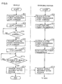
- Fig. 3 is a flowchart for illustrating overview of processing performed by vehicle 10 and charging station 90 in non-contact electric power transmission.
- Fig. 4 is a timing chart representing variation in transmission electric power and a received voltage which are varied during the course of the processing in Fig. 3 .
- step S510 when there is an empty parking frame, in step S510, power supply ECU 800 of charging station 90 broadcasts a message (emits a second signal) notifying that a situation allows charging through communication device 810, in order to guide vehicle 10 to the parking frame of charging station 90.
- Timing for charging station 90 to broadcast is, for example, at the time when it determines that no vehicle is stopped above at least one of electric power transmission devices 20A, 20B, and 20C of the plurality of electric power transmission devices 20A, 20B, and 20C and when a broadcast signal (the first signal) from a vehicle which will be described later is received.
- vehicle ECU 500 When vehicle ECU 500 receives the message notifying that the situation allows charging through communication device 510 in step S40, vehicle ECU 500 transmits a request for transmission of weak electric power for positioning through communication device 510.
- electric power transmission devices 20A, 20B, and 20C transmit in step S550, weak electric power for positioning with electric power reception device 120.
- step S50 vehicle 10 carries out positioning through automatic or manual movement of vehicle 10 (see a time point t1 in Fig. 4 ).
- vehicle ECU 500 renders relay 202 conductive and obtains magnitude of a received voltage VR which is produced across the opposing ends of resistor 201 and detected by voltage sensor 203. Since this voltage is lower than a voltage in full-scale electric power transmission, vehicle ECU 500 sets relay 210 to off so as not to be affected by power storage device 300 during detection.
- vehicle ECU 500 When magnitude of received voltage VR has exceeded a threshold value TH, vehicle ECU 500 notifies the user in step S60 of the fact that positioning has been successful through notification device 520. Thereafter, when the user gives a notification that the parking position is OK by pressing a parking switch within vehicle 10, the process proceeds to step S70 (see a time point t2 in Fig. 4 ).
- step S70 vehicle ECU 500 transmits a request for stopping transmission of weak electric power for positioning.
- step S560 power supply ECU 800 of charging station 90 receives the request for stopping transmission of weak electric power, and transmission of weak electric power for positioning by electric power transmission devices 20A, 20B, and 20C ends (see a time point t3 in Fig. 4 ).
- a voltage on a secondary side (received voltage VR) varies in accordance with a distance between the primary coils of electric power transmission devices 20A, 20B, and 20C and the secondary coil of electric power reception device 120. Then, relation of a difference in position in a horizontal direction between center of gravity O1 of the core of the primary coil and center of gravity 02 of the core of the secondary coil with received voltage VR is determined in advance, and received voltage VR corresponding to an allowable value for the difference in position in the horizontal direction between center of gravity O1 of the core of the primary coil and center of gravity 02 of the core of the secondary coil is set as threshold value TH.
- step S80 and step S580 vehicle ECU 500 and power supply ECU 800 perform pairing processing for determining with which of electric power transmission devices 20A, 20B, and 20C positioning has been achieved.
- Power supply ECU 800 differentiates a duration of on of transmission electric power for each electric power transmission device. Namely, electric power transmission device 20A turns on transmission electric power for a time period of TA, electric power transmission device 20B turns on transmission electric power for a time period of TB, and electric power transmission device 20C turns on transmission electric power for a time period of TC (see a time point t4 in Fig. 4 ).
- Vehicle ECU 500 notifies power supply ECU 800 of the duration of on of received electric power, through communication device 510.
- electric power reception device 120 receives transmission electric power from electric power transmission device 20A.
- Vehicle ECU 500 notifies power supply ECU 800 of the fact that the duration of on of received electric power is TA.
- power supply ECU 800 can know that positioning with respect to electric power transmission device 20A has been carried out.
- charging station 90 performs processing for full-scale electric power transmission from the electric power transmission device which has completed positioning (see a time point t6 in Fig. 4 ).
- electric power transmission device 20A performs processing for electric power transmission.
- vehicle 10 performs processing for full-scale electric power reception by electric power reception device 120 and power storage device 300 is charged with received electric power.
- Fig. 5 is a flowchart representing details of processing for full-scale electric power reception in step S90 in Fig. 4 and processing for full-scale electric power transmission in S590.
- step ST1 vehicle ECU 500 transmits an electric power transmission start command through communication device 510.
- step ST2 power supply ECU 800 receives the electric power transmission start command through communication device 810.
- step ST3 power supply ECU 800 has electric power transmission started.
- step ST4 vehicle ECU 500 has charging started.
- step ST5 when power storage device 300 is fully charged or charged to a prescribed amount, the process proceeds to step ST6.
- step ST6 and step ST7 vehicle ECU 500 transmits an electric power transmission stop command through communication device 510 and vehicle ECU 500 has charging stopped.
- step ST8 and ST9 power supply ECU 800 receives the electric power transmission stop command through communication device 810 and power supply ECU 800 has electric power transmission stopped.
- step ST10 when movement of vehicle 10 is sensed, the process proceeds to step ST11.
- a vehicle speed exceeds a prescribed speed
- a value obtained by summing vehicle speeds exceeds a prescribed value
- vehicle ECU 500 detects movement of vehicle 10.
- step ST11 vehicle ECU 500 transmits a vehicle movement notice message (emits the first signal) through communication device 510.
- power supply ECU 800 receives the vehicle movement notice message through communication device 810. Thereafter, the process returns to step S510, and when there is an empty parking frame as a result of movement of vehicle 10 after a parking full state, power supply ECU 800 broadcasts a message (emits the second signal) notifying that a situation allows charging, in order to guide another vehicle to the parking frame of charging station 90.
- vehicle 10 broadcasts (emits the second signal) in at least one case of when vehicle 10 moves from electric power transmission device 20A, 20B, or 20C after reception of electric power from any of electric power transmission devices 20A, 20B, and 20C is completed and when a preparatory condition for movement from electric power transmission device 20A, 20B, or 20C is satisfied after reception of electric power from electric power transmission device 20A, 20B, or 20C is completed as described above.
- the second signal is a signal for notifying that vehicle 10 can be charged, and when the charging station determines that vehicles 10 are stopped over all electric power transmission devices, it does not broadcast to the surroundings.
- the vehicle transmits a vehicle movement notice message to the charging station when the vehicle moves after end of charging, so that the charging station can sense movement of the vehicle away from the electric power transmission device and guide another vehicle to the charging station.
- step S80 and step S580 in Fig. 3 is not limited to the processing described above.
- power supply ECU 800 differs a cycle of switching between on and off of transmission electric power for each electric power transmission device. Namely, electric power transmission device 20A switches between on and off of transmission electric power every cycle ⁇ TA, electric power transmission device 20B switches between on and off of transmission electric power every cycle ⁇ TB, and electric power transmission device 20C switches between on and off of transmission electric power every cycle ⁇ TC.
- Vehicle ECU 500 notifies power supply ECU 800 of a cycle of switching between on and off of received electric power.
- vehicle ECU 500 notifies power supply ECU 800 of the fact that the cycle of switching between on and off of received electric power is set to ⁇ TA. Power supply ECU 800 thus knows that positioning with electric power transmission device 20A has been completed.
- a vehicle (10) emits a first signal when the vehicle (10) moves after reception of electric power from an electric power transmission device (20A, 20B, or 20C) by an electric power reception device (120) is completed and when a preparatory condition for the vehicle (10) to move is satisfied after reception of electric power from the electric power transmission device (20A, 20B, or 20C) by the electric power reception device (120) is completed.
- a charging station (90) receives the first signal, the charging station (90) emits a second signal notifying that a state allows charging.
Landscapes
- Engineering & Computer Science (AREA)
- Power Engineering (AREA)
- Transportation (AREA)
- Mechanical Engineering (AREA)
- Computer Networks & Wireless Communication (AREA)
- Charge And Discharge Circuits For Batteries Or The Like (AREA)
- Electric Propulsion And Braking For Vehicles (AREA)
Abstract
Description
- This nonprovisional application is based on Japanese Patent Application No.
2014-017140 - The present invention relates to a non-contact electric power transmission system.
- Japanese Patent Laying-Open No.
2013-135572 - In the system described in Japanese Patent Laying-Open No.
2013-135572 - Therefore, an object of the present invention is to provide a non-contact electric power transmission system which can sense movement of a vehicle after charging and can guide another vehicle to a parking frame of a charging station with simplified means.
- In order to solve the problem above, the present invention is directed to a non-contact electric power transmission system in which electric power is transmitted between a vehicle and a charging station in a non-contact manner, the charging station including an electric power transmission device transmitting electric power in a non-contact manner. The vehicle includes an electric power reception device receiving electric power in a non-contact manner. The vehicle emits a first signal when the vehicle moves after reception of electric power from the electric power transmission device by the electric power reception device is completed and when a preparatory condition for the vehicle to move is satisfied after reception of electric power from the electric power transmission device by the electric power reception device is completed. The charging station emits a second signal notifying that a state allows charging when the charging station receives the first signal.
- According to the present invention, with simplified means, movement of a vehicle away from an electric power transmission device after charging can be sensed and another vehicle can be guided to a charging station.
- The foregoing and other objects, features, aspects and advantages of the present invention will become more apparent from the following detailed description of the present invention when taken in conjunction with the accompanying drawings.
-
-
Fig. 1 is an overall configuration diagram of a non-contact electric power transmission system representing one example of an embodiment of the present invention. -
Fig. 2 is a diagram for illustrating parking of a vehicle at a parking frame within a charging station. -
Fig. 3 is a flowchart for illustrating overview of processing performed by a vehicle and a charging station in non-contact electric power transmission. -
Fig. 4 is a timing chart representing variation in transmission electric power and a received voltage which are varied during the course of the processing inFig. 3 . -
Fig. 5 is a flowchart representing details of processing for full-scale electric power reception in step S90 inFig. 4 and processing for full-scale electric power transmission in S590. - An embodiment of the present invention will be described hereinafter with reference to the drawings.
-
Fig. 1 is an overall configuration diagram of a non-contact electric power transmission system representing one example of an embodiment of the present invention. - Referring to
Fig. 1 , a non-contact electric power transmission system in the present embodiment is constituted of avehicle 10 on which an electricpower reception device 120 configured to be able to receive electric power in a non-contact manner is mounted and acharging station 90 including electricpower transmission devices power reception portion 100. - Details of a specific configuration of
vehicle 10 andcharging station 90 will further be described below. -
Vehicle 10 includes electricpower reception device 120, apower storage device 300, a motivepower generation apparatus 400, acommunication device 510, a vehicle ECU 500, and anotification device 520. Electricpower reception device 120 includes electricpower reception portion 100, afilter circuit 150, and arectification portion 200. -
Charging station 90 includes anexternal power supply 900, electricpower transmission devices communication device 810, and a power supply ECU 800. Electricpower transmission devices power supply portions filter circuits power transmission portions - For example, as shown in
Fig. 2 , electricpower transmission devices power reception device 120 is arranged in a lower portion of a vehicle body. A location of arrangement of electricpower reception device 120 is not limited as such. For example, when electricpower transmission devices vehicle 10, electricpower reception device 120 may be provided in an upper portion of the vehicle body. - Electric
power reception portion 100 includes a secondary coil for receiving in a non-contact manner, (AC) electric power output from any of electricpower transmission portions power transmission devices power reception portion 100 outputs received electric power torectification portion 200.Rectification portion 200 rectifies AC power received by electricpower reception portion 100 and outputs the AC power topower storage device 300.Filter circuit 150 is provided between electricpower reception portion 100 andrectification portion 200 and suppresses harmonic noise generated during electric power reception from any of electricpower transmission portions Filter circuit 150 is formed, for example, from an LC filter including an inductor and a capacitor. -
Power storage device 300 is a rechargeable DC power supply and it is implemented, for example, by such a secondary battery as a lithium ion battery or a nickel metal hydride battery. A voltage ofpower storage device 300 is, for example, around 200 V.Power storage device 300 stores not only electric power outputform rectification portion 200 but also electric power generated by motivepower generation apparatus 400. Then,power storage device 300 supplies the stored electric power to motivepower generation apparatus 400. A large-capacity capacitor can also be adopted aspower storage device 300. Though not particularly illustrated, a DC-DC converter regulating an output voltage fromrectification portion 200 may be provided betweenrectification portion 200 andpower storage device 300. - Motive
power generation apparatus 400 generates driving force for running ofvehicle 10 by using electric power stored inpower storage device 300. Though not particularly illustrated, motivepower generation apparatus 400 includes, for example, an inverter receiving electric power frompower storage device 300, a motor driven by the inverter, and drive wheels driven by the motor. Motivepower generation apparatus 400 may include a generator for chargingpower storage device 300 and an engine which can drive the generator. - Vehicle ECU 500 includes a central processing unit (CPU), a storage device, and an input/output buffer (none of which is shown), receives input of signals from various sensors and outputs control signals to each device, and controls each device in
vehicle 10. By way of example, vehicle ECU 500 controls running ofvehicle 10 and charging ofpower storage device 300. Such control is not limited to processing by software and processing with dedicated hardware (electronic circuitry) can also be performed. - A
relay 210 is provided betweenrectification portion 200 andpower storage device 300.Relay 210 is turned on by vehicle ECU 500 during charging ofpower storage device 300 by electricpower transmission devices power storage device 300 and motivepower generation apparatus 400. SMR 310 is turned on by vehicle ECU 500 when start-up of motivepower generation apparatus 400 is requested. - A
relay 202 is provided betweenrectification portion 200 andrelay 210. A voltage VR across opposing ends of aresistor 201 connected in series withrelay 202 is detected by avoltage sensor 203, and sent tovehicle ECU 500. - Vehicle ECU 500 communicates with
communication device 810 ofcharging station 90 throughcommunication device 510 during charging ofpower storage device 300 by electricpower transmission devices power supply ECU 800, information on start/stop of charging or an electric power reception condition ofvehicle 10. -
Fig. 2 is a diagram for illustrating positioning between electricpower reception device 120 and electricpower transmission device 20A with movement ofvehicle 10. Referring toFig. 2 ,vehicle 10 orcharging station 90 determines whether or not the secondary coil within electricpower reception device 120 is positioned with respect to a primary coil within electricpower transmission device 20A based on a not-shown car-mounted camera or on intensity of received electric power during test electric power transmission (transmission of weak electric power) by electricpower transmission portion 700A, and a user is notified of a result throughnotification device 520. The user movesvehicle 10 such that positional relation between electricpower reception device 120 and electricpower transmission device 20A is good for electric power transmission and reception based on information obtained fromnotification device 520. The user does not necessarily have to operate a steering wheel or an accelerator, andvehicle 10 may automatically move for positioning while the user monitors such an operation onnotification device 520. - Referring again to
Fig. 1 ,power supply portions external power supply 900 such as a commercial system power supply and generate AC power having a prescribed transmission frequency. - Electric
power transmission portions power reception portion 100. Electricpower transmission portions power supply portions power reception portion 100 ofvehicle 10 in a non-contact manner through electromagnetic field generated around electricpower transmission portions -
Filter circuits power supply portions power transmission portions power supply portions Filter circuits -
Power supply ECU 800 includes a CPU, a storage device, and an input/output buffer (none of which is shown), receives input of signals from various sensors and outputs control signals to each device, and controls each device in chargingstation 90. By way of example,power supply ECU 800 controls switching ofpower supply portions power supply portions -
Power supply ECU 800 communicates withcommunication device 510 ofvehicle 10 throughcommunication device 810 during electric power transmission tovehicle 10, and exchanges withvehicle 10, information on start/stop of charging or an electric power reception condition ofvehicle 10. - AC power having a prescribed transmission frequency is supplied from
power supply portions power transmission portions filter circuits power transmission portions power reception portion 100 ofvehicle 10 includes a coil and a capacitor, and is designed to resonate at the transmission frequency. A Q value representing resonance intensity of electricpower transmission portions power reception portion 100 is preferably 100 or higher. - When AC power is supplied from
power supply portions power transmission portions filter circuits power transmission portions power reception portion 100 through electromagnetic field formed between the primary coil included in any of electricpower transmission portions power reception portion 100. Then, energy (electric power) transferred to electricpower reception portion 100 is supplied topower storage device 300 throughfilter circuit 150 andrectification portion 200. - Though not particularly illustrated, in electric
power transmission devices power transmission portions power supply portions power transmission portions filter circuits vehicle 10 as well, an insulating transformer may be provided between electricpower reception portion 100 and rectification portion 200 (for example, between electricpower reception portion 100 and filter circuit 150). -
Fig. 3 is a flowchart for illustrating overview of processing performed byvehicle 10 and chargingstation 90 in non-contact electric power transmission.Fig. 4 is a timing chart representing variation in transmission electric power and a received voltage which are varied during the course of the processing inFig. 3 . - Referring to
Figs. 1 ,3 , and4 , when there is an empty parking frame, in step S510,power supply ECU 800 of chargingstation 90 broadcasts a message (emits a second signal) notifying that a situation allows charging throughcommunication device 810, in order to guidevehicle 10 to the parking frame of chargingstation 90. - Timing for charging
station 90 to broadcast (emit the second signal) is, for example, at the time when it determines that no vehicle is stopped above at least one of electricpower transmission devices power transmission devices - When
vehicle ECU 500 receives the message notifying that the situation allows charging throughcommunication device 510 in step S40,vehicle ECU 500 transmits a request for transmission of weak electric power for positioning throughcommunication device 510. - In charging
station 90, electricpower transmission devices power reception device 120. - In step S50,
vehicle 10 carries out positioning through automatic or manual movement of vehicle 10 (see a time point t1 inFig. 4 ). During positioning,vehicle ECU 500 rendersrelay 202 conductive and obtains magnitude of a received voltage VR which is produced across the opposing ends ofresistor 201 and detected byvoltage sensor 203. Since this voltage is lower than a voltage in full-scale electric power transmission,vehicle ECU 500 sets relay 210 to off so as not to be affected bypower storage device 300 during detection. - When magnitude of received voltage VR has exceeded a threshold value TH,
vehicle ECU 500 notifies the user in step S60 of the fact that positioning has been successful throughnotification device 520. Thereafter, when the user gives a notification that the parking position is OK by pressing a parking switch withinvehicle 10, the process proceeds to step S70 (see a time point t2 inFig. 4 ). - In step S70,
vehicle ECU 500 transmits a request for stopping transmission of weak electric power for positioning. In step S560,power supply ECU 800 of chargingstation 90 receives the request for stopping transmission of weak electric power, and transmission of weak electric power for positioning by electricpower transmission devices Fig. 4 ). - In contrast to a constant voltage on a primary side (an output voltage from electric
power transmission devices power transmission devices power reception device 120. Then, relation of a difference in position in a horizontal direction between center of gravity O1 of the core of the primary coil and center of gravity 02 of the core of the secondary coil with received voltage VR is determined in advance, and received voltage VR corresponding to an allowable value for the difference in position in the horizontal direction between center of gravity O1 of the core of the primary coil and center of gravity 02 of the core of the secondary coil is set as threshold value TH. - In step S80 and step S580,
vehicle ECU 500 andpower supply ECU 800 perform pairing processing for determining with which of electricpower transmission devices -
Power supply ECU 800 differentiates a duration of on of transmission electric power for each electric power transmission device. Namely, electricpower transmission device 20A turns on transmission electric power for a time period of TA, electricpower transmission device 20B turns on transmission electric power for a time period of TB, and electricpower transmission device 20C turns on transmission electric power for a time period of TC (see a time point t4 inFig. 4 ). -
Vehicle ECU 500 notifiespower supply ECU 800 of the duration of on of received electric power, throughcommunication device 510. In the example inFig. 4 , electricpower reception device 120 receives transmission electric power from electricpower transmission device 20A.Vehicle ECU 500 notifiespower supply ECU 800 of the fact that the duration of on of received electric power is TA. Thus,power supply ECU 800 can know that positioning with respect to electricpower transmission device 20A has been carried out. - In step S590, charging
station 90 performs processing for full-scale electric power transmission from the electric power transmission device which has completed positioning (see a time point t6 inFig. 4 ). In the example inFig. 4 , electricpower transmission device 20A performs processing for electric power transmission. In step S90,vehicle 10 performs processing for full-scale electric power reception by electricpower reception device 120 andpower storage device 300 is charged with received electric power. -
Fig. 5 is a flowchart representing details of processing for full-scale electric power reception in step S90 inFig. 4 and processing for full-scale electric power transmission in S590. - Referring to
Fig. 5 , in step ST1,vehicle ECU 500 transmits an electric power transmission start command throughcommunication device 510. In step ST2,power supply ECU 800 receives the electric power transmission start command throughcommunication device 810. - In step ST3,
power supply ECU 800 has electric power transmission started. In step ST4,vehicle ECU 500 has charging started. - In step ST5, when
power storage device 300 is fully charged or charged to a prescribed amount, the process proceeds to step ST6. - In step ST6 and step ST7,
vehicle ECU 500 transmits an electric power transmission stop command throughcommunication device 510 andvehicle ECU 500 has charging stopped. In steps ST8 and ST9,power supply ECU 800 receives the electric power transmission stop command throughcommunication device 810 andpower supply ECU 800 has electric power transmission stopped. - In step ST10, when movement of
vehicle 10 is sensed, the process proceeds to step ST11. Here, for example, when a vehicle speed exceeds a prescribed speed, when a value obtained by summing vehicle speeds exceeds a prescribed value, when a current position ofvehicle 10 obtained from a global positioning system (GPS) is distant from a position of parking frame A, B, or C by a prescribed distance or more (whenvehicle 10 moves from electricpower transmission device vehicle 10 to move is satisfied),vehicle ECU 500 detects movement ofvehicle 10. - In step ST11,
vehicle ECU 500 transmits a vehicle movement notice message (emits the first signal) throughcommunication device 510. In step ST12,power supply ECU 800 receives the vehicle movement notice message throughcommunication device 810. Thereafter, the process returns to step S510, and when there is an empty parking frame as a result of movement ofvehicle 10 after a parking full state,power supply ECU 800 broadcasts a message (emits the second signal) notifying that a situation allows charging, in order to guide another vehicle to the parking frame of chargingstation 90. - Thus, in the non-contact electric power transmission system according to the present embodiment,
vehicle 10 broadcasts (emits the second signal) in at least one case of whenvehicle 10 moves from electricpower transmission device power transmission devices power transmission device power transmission device vehicle 10 can be charged, and when the charging station determines thatvehicles 10 are stopped over all electric power transmission devices, it does not broadcast to the surroundings. Thus, when a parking lot is full, guide ofvehicle 10 to the charging station is prevented, and when there is free electricpower transmission device new vehicle 10 is guided to the charging station. - As above, according to the present embodiment, the vehicle transmits a vehicle movement notice message to the charging station when the vehicle moves after end of charging, so that the charging station can sense movement of the vehicle away from the electric power transmission device and guide another vehicle to the charging station.
- The pairing processing in step S80 and step S580 in
Fig. 3 is not limited to the processing described above. For example,power supply ECU 800 differs a cycle of switching between on and off of transmission electric power for each electric power transmission device. Namely, electricpower transmission device 20A switches between on and off of transmission electric power every cycle ΔTA, electricpower transmission device 20B switches between on and off of transmission electric power every cycle ΔTB, and electricpower transmission device 20C switches between on and off of transmission electric power every cycle ΔTC.Vehicle ECU 500 notifiespower supply ECU 800 of a cycle of switching between on and off of received electric power. For example, when electricpower reception device 120 receives transmission electric power from electricpower transmission device 20A,vehicle ECU 500 notifiespower supply ECU 800 of the fact that the cycle of switching between on and off of received electric power is set to ΔTA.Power supply ECU 800 thus knows that positioning with electricpower transmission device 20A has been completed. - Although the present invention has been described and illustrated in detail, it is clearly understood that the same is by way of illustration and example only and is not to be taken by way of limitation, the scope of the present invention being interpreted by the terms of the appended claims.
- A vehicle (10) emits a first signal when the vehicle (10) moves after reception of electric power from an electric power transmission device (20A, 20B, or 20C) by an electric power reception device (120) is completed and when a preparatory condition for the vehicle (10) to move is satisfied after reception of electric power from the electric power transmission device (20A, 20B, or 20C) by the electric power reception device (120) is completed. When a charging station (90) receives the first signal, the charging station (90) emits a second signal notifying that a state allows charging.
Claims (5)
- A non-contact electric power transmission system (10, 90) in which electric power is transmitted between a vehicle (10) and a charging station (90) in a non-contact manner,
said charging station including an electric power transmission device (20A, 20B, 20C) transmitting electric power in a non-contact manner,
said vehicle including an electric power reception device (120) receiving electric power in a non-contact manner,
said vehicle emitting a first signal when the vehicle moves after reception of electric power from said electric power transmission device by said electric power reception device is completed and when a preparatory condition for the vehicle to move is satisfied after reception of electric power from said electric power transmission device by said electric power reception device is completed, and
said charging station emitting a second signal notifying that a state allows charging when said charging station receives said first signal. - The non-contact electric power transmission system according to claim 1,
wherein
said vehicle emits said first signal when a speed of said vehicle exceeds a prescribed speed. - The non-contact electric power transmission system according to claim 1,
wherein
said vehicle emits said first signal when a value obtained by summing speeds of said vehicle exceeds a prescribed value. - The non-contact electric power transmission system according to claim 1,
wherein
said vehicle emits said first signal when a current position of said vehicle obtained from a GPS system is distant from a position of a parking frame of said charging station by a prescribed distance or more. - The non-contact electric power transmission system according to claim 1,
wherein
said vehicle emits said first signal when a shift position of said vehicle is changed from a parking position to a drive position.
Applications Claiming Priority (1)
| Application Number | Priority Date | Filing Date | Title |
|---|---|---|---|
| JP2014017140A JP5920371B2 (en) | 2014-01-31 | 2014-01-31 | Non-contact power transmission system |
Publications (3)
| Publication Number | Publication Date |
|---|---|
| EP2905170A2 true EP2905170A2 (en) | 2015-08-12 |
| EP2905170A3 EP2905170A3 (en) | 2016-01-20 |
| EP2905170B1 EP2905170B1 (en) | 2018-04-11 |
Family
ID=52358664
Family Applications (1)
| Application Number | Title | Priority Date | Filing Date |
|---|---|---|---|
| EP15151891.7A Not-in-force EP2905170B1 (en) | 2014-01-31 | 2015-01-21 | Non-contact electric power transmission system for vehicle |
Country Status (4)
| Country | Link |
|---|---|
| US (1) | US9834103B2 (en) |
| EP (1) | EP2905170B1 (en) |
| JP (1) | JP5920371B2 (en) |
| CN (1) | CN104821636B (en) |
Cited By (2)
| Publication number | Priority date | Publication date | Assignee | Title |
|---|---|---|---|---|
| WO2019052749A1 (en) * | 2017-09-13 | 2019-03-21 | Audi Ag | METHOD FOR OPERATING AN ELECTRIC CHARGING DEVICE AND RECOMMENDATION FOR AN ELECTRICALLY DRIVEN MOTOR VEHICLE AND ELECTRICAL CHARGING DEVICE AND MOTOR VEHICLE |
| EP3511194A1 (en) * | 2018-01-16 | 2019-07-17 | Bayerische Motoren Werke Aktiengesellschaft | A driving assist system and a method for positioning a vehicle over a charging station |
Families Citing this family (12)
| Publication number | Priority date | Publication date | Assignee | Title |
|---|---|---|---|---|
| JP6361132B2 (en) | 2013-12-24 | 2018-07-25 | トヨタ自動車株式会社 | Contactless power transfer system, charging station, and vehicle |
| EP3352328B1 (en) * | 2015-09-18 | 2020-12-02 | FUJI Corporation | Non-contact power supply device |
| DE102015117892A1 (en) * | 2015-10-21 | 2017-04-27 | Dr. Ing. H.C. F. Porsche Aktiengesellschaft | Method for charging or discharging a vehicle battery |
| CN106532973A (en) * | 2016-10-11 | 2017-03-22 | 中国科学院电工研究所 | Wireless charging positioning device for electric vehicle |
| WO2018076214A1 (en) * | 2016-10-26 | 2018-05-03 | 深圳市沃尔核材股份有限公司 | Alignment method for wireless charging coil, apparatus and system |
| CN109050297A (en) * | 2018-08-01 | 2018-12-21 | 西安理工大学 | Electric car shares charging unit and charging method automatically in garage under a kind of internet+mode |
| JP2020047117A (en) * | 2018-09-20 | 2020-03-26 | スミダコーポレーション株式会社 | Charging management device |
| CN111137153A (en) * | 2019-03-26 | 2020-05-12 | 青岛特来电新能源科技有限公司 | Charging system and electric vehicle |
| US12580407B2 (en) * | 2021-10-06 | 2026-03-17 | Geotab Inc. | Methods for controlling power distribution to vehicles |
| US20260061870A1 (en) * | 2022-08-16 | 2026-03-05 | Mahle International Gmbh | Charging system comprising induction charging devices |
| CN115848204B (en) * | 2022-11-16 | 2025-08-05 | 奇瑞新能源汽车股份有限公司 | Electric vehicle AC orderly charging control system and control method |
| DE102023120755A1 (en) * | 2023-08-04 | 2025-02-06 | Brusa Elektronik Ag | vehicle module for an inductive charging system |
Citations (1)
| Publication number | Priority date | Publication date | Assignee | Title |
|---|---|---|---|---|
| JP2013135572A (en) | 2011-12-27 | 2013-07-08 | Toyota Motor Corp | Non contact power reception device and non contact charging system |
Family Cites Families (24)
| Publication number | Priority date | Publication date | Assignee | Title |
|---|---|---|---|---|
| JP2005006461A (en) * | 2003-06-13 | 2005-01-06 | Panasonic Ev Energy Co Ltd | Method for controlling charging/discharging of secondary battery for automated guided vehicle |
| US7825543B2 (en) | 2005-07-12 | 2010-11-02 | Massachusetts Institute Of Technology | Wireless energy transfer |
| KR101118710B1 (en) | 2005-07-12 | 2012-03-13 | 메사추세츠 인스티튜트 오브 테크놀로지 | Wireless non-radiative energy transfer |
| JP4691000B2 (en) * | 2006-11-15 | 2011-06-01 | 三菱重工業株式会社 | Non-contact power feeding device for moving objects |
| JP4179379B2 (en) * | 2007-01-04 | 2008-11-12 | トヨタ自動車株式会社 | VEHICLE, ITS CONTROL METHOD, AND COMPUTER-READABLE RECORDING MEDIUM RECORDING PROGRAM FOR CAUSING COMPUTER TO EXECUTE VEHICLE CONTROL METHOD |
| KR101356409B1 (en) | 2007-03-27 | 2014-01-27 | 메사추세츠 인스티튜트 오브 테크놀로지 | Wireless energy transfer |
| JP2009276927A (en) * | 2008-05-13 | 2009-11-26 | Denso Corp | Empty parking space information transmitter and empty parking space guide system |
| JP5081783B2 (en) * | 2008-10-08 | 2012-11-28 | 本田技研工業株式会社 | Vehicle charging system |
| JP4905571B2 (en) | 2010-03-10 | 2012-03-28 | トヨタ自動車株式会社 | Vehicle parking assistance device and vehicle equipped with the same |
| JP5051257B2 (en) * | 2010-03-16 | 2012-10-17 | トヨタ自動車株式会社 | vehicle |
| JP5459024B2 (en) * | 2010-04-05 | 2014-04-02 | 株式会社豊田自動織機 | Control device, supply device control method and supply system |
| DE102010054470A1 (en) * | 2010-12-14 | 2012-06-14 | Conductix-Wampfler Ag | Device for inductive transmission of electrical energy |
| CN103228481B (en) * | 2011-06-20 | 2015-07-08 | 丰田自动车株式会社 | Non-contact receiving device, non-contact transmitting device, and non-contact transmitting/receiving system |
| EP2722216B1 (en) | 2011-06-20 | 2019-01-16 | Toyota Jidosha Kabushiki Kaisha | Non-contact power reception device, non-contact power transmission device, and non-contact power reception and transmission system |
| JP5772535B2 (en) | 2011-11-18 | 2015-09-02 | トヨタ自動車株式会社 | Power transmission system and vehicle |
| JP5668676B2 (en) | 2011-12-15 | 2015-02-12 | トヨタ自動車株式会社 | Power receiving device, vehicle including the same, power transmitting device, and power transmission system |
| JP2013132170A (en) | 2011-12-22 | 2013-07-04 | Toyota Motor Corp | Vehicle, non-contact power reception apparatus, non-contact transmission apparatus, non-contact feeding system, and non-contact power transmission method |
| JP5718830B2 (en) | 2012-01-16 | 2015-05-13 | トヨタ自動車株式会社 | vehicle |
| JP5825108B2 (en) | 2012-01-16 | 2015-12-02 | トヨタ自動車株式会社 | Power receiving device and power transmitting device |
| JP5810944B2 (en) | 2012-01-31 | 2015-11-11 | トヨタ自動車株式会社 | Vehicle and power transmission system |
| JP2013172502A (en) * | 2012-02-20 | 2013-09-02 | Sumitomo Electric Ind Ltd | Non-contact power receiving device, non-contact power transmission system, and non-contact power transmission method |
| JP2013225969A (en) * | 2012-04-20 | 2013-10-31 | Toyota Industries Corp | Non-contact charging management system and vehicle for the same |
| JP5747863B2 (en) * | 2012-05-11 | 2015-07-15 | トヨタ自動車株式会社 | Vehicle, power receiving device, power transmitting device, and non-contact power feeding system |
| WO2014012028A2 (en) * | 2012-07-12 | 2014-01-16 | Robert Bosch Gmbh | System and method of conversational assistance for automated tasks with integrated intelligence |
-
2014
- 2014-01-31 JP JP2014017140A patent/JP5920371B2/en not_active Expired - Fee Related
-
2015
- 2015-01-09 US US14/593,256 patent/US9834103B2/en not_active Expired - Fee Related
- 2015-01-21 EP EP15151891.7A patent/EP2905170B1/en not_active Not-in-force
- 2015-01-30 CN CN201510050265.7A patent/CN104821636B/en not_active Expired - Fee Related
Patent Citations (1)
| Publication number | Priority date | Publication date | Assignee | Title |
|---|---|---|---|---|
| JP2013135572A (en) | 2011-12-27 | 2013-07-08 | Toyota Motor Corp | Non contact power reception device and non contact charging system |
Cited By (3)
| Publication number | Priority date | Publication date | Assignee | Title |
|---|---|---|---|---|
| WO2019052749A1 (en) * | 2017-09-13 | 2019-03-21 | Audi Ag | METHOD FOR OPERATING AN ELECTRIC CHARGING DEVICE AND RECOMMENDATION FOR AN ELECTRICALLY DRIVEN MOTOR VEHICLE AND ELECTRICAL CHARGING DEVICE AND MOTOR VEHICLE |
| US11618333B2 (en) | 2017-09-13 | 2023-04-04 | Audi Ag | Method for operating an electrical charging device and driving recommendation for an electrically driveable motor vehicle and electric charging device and motor vehicle |
| EP3511194A1 (en) * | 2018-01-16 | 2019-07-17 | Bayerische Motoren Werke Aktiengesellschaft | A driving assist system and a method for positioning a vehicle over a charging station |
Also Published As
| Publication number | Publication date |
|---|---|
| JP2015144527A (en) | 2015-08-06 |
| US9834103B2 (en) | 2017-12-05 |
| JP5920371B2 (en) | 2016-05-18 |
| EP2905170B1 (en) | 2018-04-11 |
| US20150217650A1 (en) | 2015-08-06 |
| EP2905170A3 (en) | 2016-01-20 |
| CN104821636A (en) | 2015-08-05 |
| CN104821636B (en) | 2017-10-20 |
Similar Documents
| Publication | Publication Date | Title |
|---|---|---|
| EP2905170B1 (en) | Non-contact electric power transmission system for vehicle | |
| US10622827B2 (en) | Non-contact electric power transmission system, charging station, and vehicle | |
| JP6260262B2 (en) | Non-contact power transmission system and control method thereof | |
| US10899234B2 (en) | Non-contact electric power transmission system, charging station, and vehicle | |
| US9637015B2 (en) | Non-contact electric power transmission system and charging station | |
| US9623759B2 (en) | Non-contact electric power transmission system and charging station | |
| JP2015100246A (en) | Non-contact power transmission system, charging station and vehicle | |
| JP2018078793A (en) | Vehicle, power receiving device and power transmitting device |
Legal Events
| Date | Code | Title | Description |
|---|---|---|---|
| PUAI | Public reference made under article 153(3) epc to a published international application that has entered the european phase |
Free format text: ORIGINAL CODE: 0009012 |
|
| 17P | Request for examination filed |
Effective date: 20150121 |
|
| AK | Designated contracting states |
Kind code of ref document: A2 Designated state(s): AL AT BE BG CH CY CZ DE DK EE ES FI FR GB GR HR HU IE IS IT LI LT LU LV MC MK MT NL NO PL PT RO RS SE SI SK SM TR |
|
| AX | Request for extension of the european patent |
Extension state: BA ME |
|
| PUAL | Search report despatched |
Free format text: ORIGINAL CODE: 0009013 |
|
| AK | Designated contracting states |
Kind code of ref document: A3 Designated state(s): AL AT BE BG CH CY CZ DE DK EE ES FI FR GB GR HR HU IE IS IT LI LT LU LV MC MK MT NL NO PL PT RO RS SE SI SK SM TR |
|
| AX | Request for extension of the european patent |
Extension state: BA ME |
|
| RIC1 | Information provided on ipc code assigned before grant |
Ipc: B60L 11/18 20060101AFI20151211BHEP |
|
| STAA | Information on the status of an ep patent application or granted ep patent |
Free format text: STATUS: EXAMINATION IS IN PROGRESS |
|
| 17Q | First examination report despatched |
Effective date: 20170113 |
|
| GRAP | Despatch of communication of intention to grant a patent |
Free format text: ORIGINAL CODE: EPIDOSNIGR1 |
|
| STAA | Information on the status of an ep patent application or granted ep patent |
Free format text: STATUS: GRANT OF PATENT IS INTENDED |
|
| INTG | Intention to grant announced |
Effective date: 20171025 |
|
| GRAS | Grant fee paid |
Free format text: ORIGINAL CODE: EPIDOSNIGR3 |
|
| GRAA | (expected) grant |
Free format text: ORIGINAL CODE: 0009210 |
|
| STAA | Information on the status of an ep patent application or granted ep patent |
Free format text: STATUS: THE PATENT HAS BEEN GRANTED |
|
| AK | Designated contracting states |
Kind code of ref document: B1 Designated state(s): AL AT BE BG CH CY CZ DE DK EE ES FI FR GB GR HR HU IE IS IT LI LT LU LV MC MK MT NL NO PL PT RO RS SE SI SK SM TR |
|
| REG | Reference to a national code |
Ref country code: GB Ref legal event code: FG4D |
|
| REG | Reference to a national code |
Ref country code: CH Ref legal event code: EP |
|
| REG | Reference to a national code |
Ref country code: AT Ref legal event code: REF Ref document number: 987646 Country of ref document: AT Kind code of ref document: T Effective date: 20180415 |
|
| REG | Reference to a national code |
Ref country code: IE Ref legal event code: FG4D |
|
| REG | Reference to a national code |
Ref country code: DE Ref legal event code: R096 Ref document number: 602015009703 Country of ref document: DE |
|
| REG | Reference to a national code |
Ref country code: NL Ref legal event code: MP Effective date: 20180411 |
|
| REG | Reference to a national code |
Ref country code: LT Ref legal event code: MG4D |
|
| REG | Reference to a national code |
Ref country code: DE Ref legal event code: R084 Ref document number: 602015009703 Country of ref document: DE |
|
| PG25 | Lapsed in a contracting state [announced via postgrant information from national office to epo] |
Ref country code: NL Free format text: LAPSE BECAUSE OF FAILURE TO SUBMIT A TRANSLATION OF THE DESCRIPTION OR TO PAY THE FEE WITHIN THE PRESCRIBED TIME-LIMIT Effective date: 20180411 |
|
| REG | Reference to a national code |
Ref country code: GB Ref legal event code: 746 Effective date: 20180918 |
|
| PG25 | Lapsed in a contracting state [announced via postgrant information from national office to epo] |
Ref country code: NO Free format text: LAPSE BECAUSE OF FAILURE TO SUBMIT A TRANSLATION OF THE DESCRIPTION OR TO PAY THE FEE WITHIN THE PRESCRIBED TIME-LIMIT Effective date: 20180711 Ref country code: BG Free format text: LAPSE BECAUSE OF FAILURE TO SUBMIT A TRANSLATION OF THE DESCRIPTION OR TO PAY THE FEE WITHIN THE PRESCRIBED TIME-LIMIT Effective date: 20180711 Ref country code: AL Free format text: LAPSE BECAUSE OF FAILURE TO SUBMIT A TRANSLATION OF THE DESCRIPTION OR TO PAY THE FEE WITHIN THE PRESCRIBED TIME-LIMIT Effective date: 20180411 Ref country code: FI Free format text: LAPSE BECAUSE OF FAILURE TO SUBMIT A TRANSLATION OF THE DESCRIPTION OR TO PAY THE FEE WITHIN THE PRESCRIBED TIME-LIMIT Effective date: 20180411 Ref country code: SE Free format text: LAPSE BECAUSE OF FAILURE TO SUBMIT A TRANSLATION OF THE DESCRIPTION OR TO PAY THE FEE WITHIN THE PRESCRIBED TIME-LIMIT Effective date: 20180411 Ref country code: ES Free format text: LAPSE BECAUSE OF FAILURE TO SUBMIT A TRANSLATION OF THE DESCRIPTION OR TO PAY THE FEE WITHIN THE PRESCRIBED TIME-LIMIT Effective date: 20180411 Ref country code: PL Free format text: LAPSE BECAUSE OF FAILURE TO SUBMIT A TRANSLATION OF THE DESCRIPTION OR TO PAY THE FEE WITHIN THE PRESCRIBED TIME-LIMIT Effective date: 20180411 Ref country code: LT Free format text: LAPSE BECAUSE OF FAILURE TO SUBMIT A TRANSLATION OF THE DESCRIPTION OR TO PAY THE FEE WITHIN THE PRESCRIBED TIME-LIMIT Effective date: 20180411 |
|
| PG25 | Lapsed in a contracting state [announced via postgrant information from national office to epo] |
Ref country code: LV Free format text: LAPSE BECAUSE OF FAILURE TO SUBMIT A TRANSLATION OF THE DESCRIPTION OR TO PAY THE FEE WITHIN THE PRESCRIBED TIME-LIMIT Effective date: 20180411 Ref country code: HR Free format text: LAPSE BECAUSE OF FAILURE TO SUBMIT A TRANSLATION OF THE DESCRIPTION OR TO PAY THE FEE WITHIN THE PRESCRIBED TIME-LIMIT Effective date: 20180411 Ref country code: GR Free format text: LAPSE BECAUSE OF FAILURE TO SUBMIT A TRANSLATION OF THE DESCRIPTION OR TO PAY THE FEE WITHIN THE PRESCRIBED TIME-LIMIT Effective date: 20180712 Ref country code: RS Free format text: LAPSE BECAUSE OF FAILURE TO SUBMIT A TRANSLATION OF THE DESCRIPTION OR TO PAY THE FEE WITHIN THE PRESCRIBED TIME-LIMIT Effective date: 20180411 |
|
| REG | Reference to a national code |
Ref country code: AT Ref legal event code: MK05 Ref document number: 987646 Country of ref document: AT Kind code of ref document: T Effective date: 20180411 |
|
| PG25 | Lapsed in a contracting state [announced via postgrant information from national office to epo] |
Ref country code: PT Free format text: LAPSE BECAUSE OF FAILURE TO SUBMIT A TRANSLATION OF THE DESCRIPTION OR TO PAY THE FEE WITHIN THE PRESCRIBED TIME-LIMIT Effective date: 20180813 |
|
| REG | Reference to a national code |
Ref country code: DE Ref legal event code: R097 Ref document number: 602015009703 Country of ref document: DE |
|
| REG | Reference to a national code |
Ref country code: DE Ref legal event code: R079 Ref document number: 602015009703 Country of ref document: DE Free format text: PREVIOUS MAIN CLASS: B60L0011180000 Ipc: B60L0050500000 |
|
| PG25 | Lapsed in a contracting state [announced via postgrant information from national office to epo] |
Ref country code: EE Free format text: LAPSE BECAUSE OF FAILURE TO SUBMIT A TRANSLATION OF THE DESCRIPTION OR TO PAY THE FEE WITHIN THE PRESCRIBED TIME-LIMIT Effective date: 20180411 Ref country code: DK Free format text: LAPSE BECAUSE OF FAILURE TO SUBMIT A TRANSLATION OF THE DESCRIPTION OR TO PAY THE FEE WITHIN THE PRESCRIBED TIME-LIMIT Effective date: 20180411 Ref country code: RO Free format text: LAPSE BECAUSE OF FAILURE TO SUBMIT A TRANSLATION OF THE DESCRIPTION OR TO PAY THE FEE WITHIN THE PRESCRIBED TIME-LIMIT Effective date: 20180411 Ref country code: AT Free format text: LAPSE BECAUSE OF FAILURE TO SUBMIT A TRANSLATION OF THE DESCRIPTION OR TO PAY THE FEE WITHIN THE PRESCRIBED TIME-LIMIT Effective date: 20180411 Ref country code: CZ Free format text: LAPSE BECAUSE OF FAILURE TO SUBMIT A TRANSLATION OF THE DESCRIPTION OR TO PAY THE FEE WITHIN THE PRESCRIBED TIME-LIMIT Effective date: 20180411 Ref country code: SK Free format text: LAPSE BECAUSE OF FAILURE TO SUBMIT A TRANSLATION OF THE DESCRIPTION OR TO PAY THE FEE WITHIN THE PRESCRIBED TIME-LIMIT Effective date: 20180411 |
|
| PLBE | No opposition filed within time limit |
Free format text: ORIGINAL CODE: 0009261 |
|
| STAA | Information on the status of an ep patent application or granted ep patent |
Free format text: STATUS: NO OPPOSITION FILED WITHIN TIME LIMIT |
|
| PG25 | Lapsed in a contracting state [announced via postgrant information from national office to epo] |
Ref country code: SM Free format text: LAPSE BECAUSE OF FAILURE TO SUBMIT A TRANSLATION OF THE DESCRIPTION OR TO PAY THE FEE WITHIN THE PRESCRIBED TIME-LIMIT Effective date: 20180411 Ref country code: IT Free format text: LAPSE BECAUSE OF FAILURE TO SUBMIT A TRANSLATION OF THE DESCRIPTION OR TO PAY THE FEE WITHIN THE PRESCRIBED TIME-LIMIT Effective date: 20180411 |
|
| 26N | No opposition filed |
Effective date: 20190114 |
|
| PG25 | Lapsed in a contracting state [announced via postgrant information from national office to epo] |
Ref country code: SI Free format text: LAPSE BECAUSE OF FAILURE TO SUBMIT A TRANSLATION OF THE DESCRIPTION OR TO PAY THE FEE WITHIN THE PRESCRIBED TIME-LIMIT Effective date: 20180411 |
|
| PG25 | Lapsed in a contracting state [announced via postgrant information from national office to epo] |
Ref country code: MC Free format text: LAPSE BECAUSE OF FAILURE TO SUBMIT A TRANSLATION OF THE DESCRIPTION OR TO PAY THE FEE WITHIN THE PRESCRIBED TIME-LIMIT Effective date: 20180411 |
|
| REG | Reference to a national code |
Ref country code: CH Ref legal event code: PL |
|
| PG25 | Lapsed in a contracting state [announced via postgrant information from national office to epo] |
Ref country code: LU Free format text: LAPSE BECAUSE OF NON-PAYMENT OF DUE FEES Effective date: 20190121 |
|
| REG | Reference to a national code |
Ref country code: BE Ref legal event code: MM Effective date: 20190131 |
|
| REG | Reference to a national code |
Ref country code: IE Ref legal event code: MM4A |
|
| PG25 | Lapsed in a contracting state [announced via postgrant information from national office to epo] |
Ref country code: BE Free format text: LAPSE BECAUSE OF NON-PAYMENT OF DUE FEES Effective date: 20190131 |
|
| PG25 | Lapsed in a contracting state [announced via postgrant information from national office to epo] |
Ref country code: LI Free format text: LAPSE BECAUSE OF NON-PAYMENT OF DUE FEES Effective date: 20190131 Ref country code: CH Free format text: LAPSE BECAUSE OF NON-PAYMENT OF DUE FEES Effective date: 20190131 |
|
| PG25 | Lapsed in a contracting state [announced via postgrant information from national office to epo] |
Ref country code: IE Free format text: LAPSE BECAUSE OF NON-PAYMENT OF DUE FEES Effective date: 20190121 |
|
| PG25 | Lapsed in a contracting state [announced via postgrant information from national office to epo] |
Ref country code: TR Free format text: LAPSE BECAUSE OF FAILURE TO SUBMIT A TRANSLATION OF THE DESCRIPTION OR TO PAY THE FEE WITHIN THE PRESCRIBED TIME-LIMIT Effective date: 20180411 |
|
| PG25 | Lapsed in a contracting state [announced via postgrant information from national office to epo] |
Ref country code: MT Free format text: LAPSE BECAUSE OF NON-PAYMENT OF DUE FEES Effective date: 20190121 |
|
| PG25 | Lapsed in a contracting state [announced via postgrant information from national office to epo] |
Ref country code: CY Free format text: LAPSE BECAUSE OF FAILURE TO SUBMIT A TRANSLATION OF THE DESCRIPTION OR TO PAY THE FEE WITHIN THE PRESCRIBED TIME-LIMIT Effective date: 20180411 |
|
| PG25 | Lapsed in a contracting state [announced via postgrant information from national office to epo] |
Ref country code: IS Free format text: LAPSE BECAUSE OF FAILURE TO SUBMIT A TRANSLATION OF THE DESCRIPTION OR TO PAY THE FEE WITHIN THE PRESCRIBED TIME-LIMIT Effective date: 20180811 |
|
| PG25 | Lapsed in a contracting state [announced via postgrant information from national office to epo] |
Ref country code: HU Free format text: LAPSE BECAUSE OF FAILURE TO SUBMIT A TRANSLATION OF THE DESCRIPTION OR TO PAY THE FEE WITHIN THE PRESCRIBED TIME-LIMIT; INVALID AB INITIO Effective date: 20150121 |
|
| PGFP | Annual fee paid to national office [announced via postgrant information from national office to epo] |
Ref country code: GB Payment date: 20211206 Year of fee payment: 8 Ref country code: FR Payment date: 20211217 Year of fee payment: 8 |
|
| PGFP | Annual fee paid to national office [announced via postgrant information from national office to epo] |
Ref country code: DE Payment date: 20211130 Year of fee payment: 8 |
|
| PG25 | Lapsed in a contracting state [announced via postgrant information from national office to epo] |
Ref country code: MK Free format text: LAPSE BECAUSE OF FAILURE TO SUBMIT A TRANSLATION OF THE DESCRIPTION OR TO PAY THE FEE WITHIN THE PRESCRIBED TIME-LIMIT Effective date: 20180411 |
|
| REG | Reference to a national code |
Ref country code: DE Ref legal event code: R119 Ref document number: 602015009703 Country of ref document: DE |
|
| GBPC | Gb: european patent ceased through non-payment of renewal fee |
Effective date: 20230121 |
|
| PG25 | Lapsed in a contracting state [announced via postgrant information from national office to epo] |
Ref country code: GB Free format text: LAPSE BECAUSE OF NON-PAYMENT OF DUE FEES Effective date: 20230121 Ref country code: DE Free format text: LAPSE BECAUSE OF NON-PAYMENT OF DUE FEES Effective date: 20230801 |
|
| PG25 | Lapsed in a contracting state [announced via postgrant information from national office to epo] |
Ref country code: FR Free format text: LAPSE BECAUSE OF NON-PAYMENT OF DUE FEES Effective date: 20230131 |