EP2905165A1 - Motor fault detection device for electric automobile - Google Patents
Motor fault detection device for electric automobile Download PDFInfo
- Publication number
- EP2905165A1 EP2905165A1 EP13844458.3A EP13844458A EP2905165A1 EP 2905165 A1 EP2905165 A1 EP 2905165A1 EP 13844458 A EP13844458 A EP 13844458A EP 2905165 A1 EP2905165 A1 EP 2905165A1
- Authority
- EP
- European Patent Office
- Prior art keywords
- electric motor
- abnormality
- vehicle
- motor unit
- electric
- Prior art date
- Legal status (The legal status is an assumption and is not a legal conclusion. Google has not performed a legal analysis and makes no representation as to the accuracy of the status listed.)
- Withdrawn
Links
- 238000001514 detection method Methods 0.000 title claims abstract description 35
- 230000005856 abnormality Effects 0.000 claims abstract description 121
- 239000003638 chemical reducing agent Substances 0.000 claims description 4
- 238000010586 diagram Methods 0.000 description 8
- 101150069538 ROT1 gene Proteins 0.000 description 4
- 238000000034 method Methods 0.000 description 4
- 230000002441 reversible effect Effects 0.000 description 4
- 230000002159 abnormal effect Effects 0.000 description 3
- 230000007423 decrease Effects 0.000 description 2
- 230000003247 decreasing effect Effects 0.000 description 2
- 230000000694 effects Effects 0.000 description 2
- 238000009499 grossing Methods 0.000 description 2
- 238000012986 modification Methods 0.000 description 2
- 230000004048 modification Effects 0.000 description 2
- 230000001172 regenerating effect Effects 0.000 description 2
- 238000005070 sampling Methods 0.000 description 2
- 230000001360 synchronised effect Effects 0.000 description 2
- 239000003990 capacitor Substances 0.000 description 1
- 238000010276 construction Methods 0.000 description 1
- 230000007257 malfunction Effects 0.000 description 1
- 239000004065 semiconductor Substances 0.000 description 1
- 238000004088 simulation Methods 0.000 description 1
Images




Classifications
-
- B—PERFORMING OPERATIONS; TRANSPORTING
- B60—VEHICLES IN GENERAL
- B60L—PROPULSION OF ELECTRICALLY-PROPELLED VEHICLES; SUPPLYING ELECTRIC POWER FOR AUXILIARY EQUIPMENT OF ELECTRICALLY-PROPELLED VEHICLES; ELECTRODYNAMIC BRAKE SYSTEMS FOR VEHICLES IN GENERAL; MAGNETIC SUSPENSION OR LEVITATION FOR VEHICLES; MONITORING OPERATING VARIABLES OF ELECTRICALLY-PROPELLED VEHICLES; ELECTRIC SAFETY DEVICES FOR ELECTRICALLY-PROPELLED VEHICLES
- B60L3/00—Electric devices on electrically-propelled vehicles for safety purposes; Monitoring operating variables, e.g. speed, deceleration or energy consumption
- B60L3/0023—Detecting, eliminating, remedying or compensating for drive train abnormalities, e.g. failures within the drive train
- B60L3/0061—Detecting, eliminating, remedying or compensating for drive train abnormalities, e.g. failures within the drive train relating to electrical machines
-
- B—PERFORMING OPERATIONS; TRANSPORTING
- B60—VEHICLES IN GENERAL
- B60L—PROPULSION OF ELECTRICALLY-PROPELLED VEHICLES; SUPPLYING ELECTRIC POWER FOR AUXILIARY EQUIPMENT OF ELECTRICALLY-PROPELLED VEHICLES; ELECTRODYNAMIC BRAKE SYSTEMS FOR VEHICLES IN GENERAL; MAGNETIC SUSPENSION OR LEVITATION FOR VEHICLES; MONITORING OPERATING VARIABLES OF ELECTRICALLY-PROPELLED VEHICLES; ELECTRIC SAFETY DEVICES FOR ELECTRICALLY-PROPELLED VEHICLES
- B60L15/00—Methods, circuits, or devices for controlling the traction-motor speed of electrically-propelled vehicles
- B60L15/007—Physical arrangements or structures of drive train converters specially adapted for the propulsion motors of electric vehicles
-
- B—PERFORMING OPERATIONS; TRANSPORTING
- B60—VEHICLES IN GENERAL
- B60L—PROPULSION OF ELECTRICALLY-PROPELLED VEHICLES; SUPPLYING ELECTRIC POWER FOR AUXILIARY EQUIPMENT OF ELECTRICALLY-PROPELLED VEHICLES; ELECTRODYNAMIC BRAKE SYSTEMS FOR VEHICLES IN GENERAL; MAGNETIC SUSPENSION OR LEVITATION FOR VEHICLES; MONITORING OPERATING VARIABLES OF ELECTRICALLY-PROPELLED VEHICLES; ELECTRIC SAFETY DEVICES FOR ELECTRICALLY-PROPELLED VEHICLES
- B60L15/00—Methods, circuits, or devices for controlling the traction-motor speed of electrically-propelled vehicles
- B60L15/20—Methods, circuits, or devices for controlling the traction-motor speed of electrically-propelled vehicles for control of the vehicle or its driving motor to achieve a desired performance, e.g. speed, torque, programmed variation of speed
- B60L15/2036—Electric differentials, e.g. for supporting steering vehicles
-
- B—PERFORMING OPERATIONS; TRANSPORTING
- B60—VEHICLES IN GENERAL
- B60L—PROPULSION OF ELECTRICALLY-PROPELLED VEHICLES; SUPPLYING ELECTRIC POWER FOR AUXILIARY EQUIPMENT OF ELECTRICALLY-PROPELLED VEHICLES; ELECTRODYNAMIC BRAKE SYSTEMS FOR VEHICLES IN GENERAL; MAGNETIC SUSPENSION OR LEVITATION FOR VEHICLES; MONITORING OPERATING VARIABLES OF ELECTRICALLY-PROPELLED VEHICLES; ELECTRIC SAFETY DEVICES FOR ELECTRICALLY-PROPELLED VEHICLES
- B60L3/00—Electric devices on electrically-propelled vehicles for safety purposes; Monitoring operating variables, e.g. speed, deceleration or energy consumption
- B60L3/04—Cutting off the power supply under fault conditions
-
- B—PERFORMING OPERATIONS; TRANSPORTING
- B60—VEHICLES IN GENERAL
- B60L—PROPULSION OF ELECTRICALLY-PROPELLED VEHICLES; SUPPLYING ELECTRIC POWER FOR AUXILIARY EQUIPMENT OF ELECTRICALLY-PROPELLED VEHICLES; ELECTRODYNAMIC BRAKE SYSTEMS FOR VEHICLES IN GENERAL; MAGNETIC SUSPENSION OR LEVITATION FOR VEHICLES; MONITORING OPERATING VARIABLES OF ELECTRICALLY-PROPELLED VEHICLES; ELECTRIC SAFETY DEVICES FOR ELECTRICALLY-PROPELLED VEHICLES
- B60L3/00—Electric devices on electrically-propelled vehicles for safety purposes; Monitoring operating variables, e.g. speed, deceleration or energy consumption
- B60L3/12—Recording operating variables ; Monitoring of operating variables
-
- B—PERFORMING OPERATIONS; TRANSPORTING
- B60—VEHICLES IN GENERAL
- B60L—PROPULSION OF ELECTRICALLY-PROPELLED VEHICLES; SUPPLYING ELECTRIC POWER FOR AUXILIARY EQUIPMENT OF ELECTRICALLY-PROPELLED VEHICLES; ELECTRODYNAMIC BRAKE SYSTEMS FOR VEHICLES IN GENERAL; MAGNETIC SUSPENSION OR LEVITATION FOR VEHICLES; MONITORING OPERATING VARIABLES OF ELECTRICALLY-PROPELLED VEHICLES; ELECTRIC SAFETY DEVICES FOR ELECTRICALLY-PROPELLED VEHICLES
- B60L50/00—Electric propulsion with power supplied within the vehicle
- B60L50/50—Electric propulsion with power supplied within the vehicle using propulsion power supplied by batteries or fuel cells
- B60L50/51—Electric propulsion with power supplied within the vehicle using propulsion power supplied by batteries or fuel cells characterised by AC-motors
-
- B—PERFORMING OPERATIONS; TRANSPORTING
- B60—VEHICLES IN GENERAL
- B60L—PROPULSION OF ELECTRICALLY-PROPELLED VEHICLES; SUPPLYING ELECTRIC POWER FOR AUXILIARY EQUIPMENT OF ELECTRICALLY-PROPELLED VEHICLES; ELECTRODYNAMIC BRAKE SYSTEMS FOR VEHICLES IN GENERAL; MAGNETIC SUSPENSION OR LEVITATION FOR VEHICLES; MONITORING OPERATING VARIABLES OF ELECTRICALLY-PROPELLED VEHICLES; ELECTRIC SAFETY DEVICES FOR ELECTRICALLY-PROPELLED VEHICLES
- B60L2220/00—Electrical machine types; Structures or applications thereof
- B60L2220/40—Electrical machine applications
- B60L2220/44—Wheel Hub motors, i.e. integrated in the wheel hub
-
- B—PERFORMING OPERATIONS; TRANSPORTING
- B60—VEHICLES IN GENERAL
- B60L—PROPULSION OF ELECTRICALLY-PROPELLED VEHICLES; SUPPLYING ELECTRIC POWER FOR AUXILIARY EQUIPMENT OF ELECTRICALLY-PROPELLED VEHICLES; ELECTRODYNAMIC BRAKE SYSTEMS FOR VEHICLES IN GENERAL; MAGNETIC SUSPENSION OR LEVITATION FOR VEHICLES; MONITORING OPERATING VARIABLES OF ELECTRICALLY-PROPELLED VEHICLES; ELECTRIC SAFETY DEVICES FOR ELECTRICALLY-PROPELLED VEHICLES
- B60L2240/00—Control parameters of input or output; Target parameters
- B60L2240/10—Vehicle control parameters
- B60L2240/12—Speed
-
- B—PERFORMING OPERATIONS; TRANSPORTING
- B60—VEHICLES IN GENERAL
- B60L—PROPULSION OF ELECTRICALLY-PROPELLED VEHICLES; SUPPLYING ELECTRIC POWER FOR AUXILIARY EQUIPMENT OF ELECTRICALLY-PROPELLED VEHICLES; ELECTRODYNAMIC BRAKE SYSTEMS FOR VEHICLES IN GENERAL; MAGNETIC SUSPENSION OR LEVITATION FOR VEHICLES; MONITORING OPERATING VARIABLES OF ELECTRICALLY-PROPELLED VEHICLES; ELECTRIC SAFETY DEVICES FOR ELECTRICALLY-PROPELLED VEHICLES
- B60L2240/00—Control parameters of input or output; Target parameters
- B60L2240/10—Vehicle control parameters
- B60L2240/24—Steering angle
-
- B—PERFORMING OPERATIONS; TRANSPORTING
- B60—VEHICLES IN GENERAL
- B60L—PROPULSION OF ELECTRICALLY-PROPELLED VEHICLES; SUPPLYING ELECTRIC POWER FOR AUXILIARY EQUIPMENT OF ELECTRICALLY-PROPELLED VEHICLES; ELECTRODYNAMIC BRAKE SYSTEMS FOR VEHICLES IN GENERAL; MAGNETIC SUSPENSION OR LEVITATION FOR VEHICLES; MONITORING OPERATING VARIABLES OF ELECTRICALLY-PROPELLED VEHICLES; ELECTRIC SAFETY DEVICES FOR ELECTRICALLY-PROPELLED VEHICLES
- B60L2240/00—Control parameters of input or output; Target parameters
- B60L2240/40—Drive Train control parameters
- B60L2240/42—Drive Train control parameters related to electric machines
- B60L2240/421—Speed
-
- B—PERFORMING OPERATIONS; TRANSPORTING
- B60—VEHICLES IN GENERAL
- B60L—PROPULSION OF ELECTRICALLY-PROPELLED VEHICLES; SUPPLYING ELECTRIC POWER FOR AUXILIARY EQUIPMENT OF ELECTRICALLY-PROPELLED VEHICLES; ELECTRODYNAMIC BRAKE SYSTEMS FOR VEHICLES IN GENERAL; MAGNETIC SUSPENSION OR LEVITATION FOR VEHICLES; MONITORING OPERATING VARIABLES OF ELECTRICALLY-PROPELLED VEHICLES; ELECTRIC SAFETY DEVICES FOR ELECTRICALLY-PROPELLED VEHICLES
- B60L2260/00—Operating Modes
- B60L2260/20—Drive modes; Transition between modes
- B60L2260/28—Four wheel or all wheel drive
-
- Y—GENERAL TAGGING OF NEW TECHNOLOGICAL DEVELOPMENTS; GENERAL TAGGING OF CROSS-SECTIONAL TECHNOLOGIES SPANNING OVER SEVERAL SECTIONS OF THE IPC; TECHNICAL SUBJECTS COVERED BY FORMER USPC CROSS-REFERENCE ART COLLECTIONS [XRACs] AND DIGESTS
- Y02—TECHNOLOGIES OR APPLICATIONS FOR MITIGATION OR ADAPTATION AGAINST CLIMATE CHANGE
- Y02T—CLIMATE CHANGE MITIGATION TECHNOLOGIES RELATED TO TRANSPORTATION
- Y02T10/00—Road transport of goods or passengers
- Y02T10/60—Other road transportation technologies with climate change mitigation effect
- Y02T10/64—Electric machine technologies in electromobility
-
- Y—GENERAL TAGGING OF NEW TECHNOLOGICAL DEVELOPMENTS; GENERAL TAGGING OF CROSS-SECTIONAL TECHNOLOGIES SPANNING OVER SEVERAL SECTIONS OF THE IPC; TECHNICAL SUBJECTS COVERED BY FORMER USPC CROSS-REFERENCE ART COLLECTIONS [XRACs] AND DIGESTS
- Y02—TECHNOLOGIES OR APPLICATIONS FOR MITIGATION OR ADAPTATION AGAINST CLIMATE CHANGE
- Y02T—CLIMATE CHANGE MITIGATION TECHNOLOGIES RELATED TO TRANSPORTATION
- Y02T10/00—Road transport of goods or passengers
- Y02T10/60—Other road transportation technologies with climate change mitigation effect
- Y02T10/70—Energy storage systems for electromobility, e.g. batteries
-
- Y—GENERAL TAGGING OF NEW TECHNOLOGICAL DEVELOPMENTS; GENERAL TAGGING OF CROSS-SECTIONAL TECHNOLOGIES SPANNING OVER SEVERAL SECTIONS OF THE IPC; TECHNICAL SUBJECTS COVERED BY FORMER USPC CROSS-REFERENCE ART COLLECTIONS [XRACs] AND DIGESTS
- Y02—TECHNOLOGIES OR APPLICATIONS FOR MITIGATION OR ADAPTATION AGAINST CLIMATE CHANGE
- Y02T—CLIMATE CHANGE MITIGATION TECHNOLOGIES RELATED TO TRANSPORTATION
- Y02T10/00—Road transport of goods or passengers
- Y02T10/60—Other road transportation technologies with climate change mitigation effect
- Y02T10/72—Electric energy management in electromobility
Definitions
- the present invention relates to a motor abnormality detection apparatus for an electric vehicle, and relates to a technique capable of accurately detecting an abnormality of a drive device.
- a control method and apparatus for an electric vehicle have been proposed which allow the vehicle to continue to travel, when an abnormality such as malfunction in a drive device or an electric motor unit in an in-wheel motor drive system for the electric vehicle occurs, by another electric motor unit (Patent Documents 1 and 2).
- Patent Documents 1 and 2 In an electric vehicle which includes a drive device independently driving at least left and right wheels and including an electric motor unit, when an abnormality of either one of the drive devices is occurs, a detector for detecting the abnormality of the drive device is meaningful. The detector will be described in the following 1 to 3.
- the above-described detector for detecting an abnormality of the drive device has the following problems.
- An object of the present invention is to provide a motor abnormality detection apparatus for an electric vehicle which is able to accurately detect an abnormality of electric motor units in the electric vehicle and allows the cost to be reduced as compared to the conventional art.
- a motor abnormality detection apparatus for an electric vehicle is a motor abnormality detection apparatus having a drive device 8 including an electric motor unit 6.
- the motor abnormality detection apparatus is configured to detect an abnormality of the electric motor unit 6.
- the electric motor unit 6 includes electric motor units 6, 6 which independently drive at least left and right wheels 2, 2, respectively.
- the motor abnormality detection apparatus includes: a steering angle sensor 15b configured to sense a steering angle of the vehicle; rotation angle sensors 36 configured to sense rotation angles of the respective electric motor units 6; a vehicle speed sensor 9 configured to sense a vehicle speed; a control map 10a configured to store a relationship among a value associated with a difference between rotation angles of the left and right electric motor units 6, 6 that operate normally, that is, the motor units in a normal state, a steering angle, and a vehicle speed; and an abnormality determiner 11 configured to determine the abnormality of the electric motor unit 6, when a difference between rotation angles of the left and right electric motor units 6, 6 which are sensed by the rotation angle sensors 36 deviates from a value associated with the difference between the rotation angles which is retrieved from the control map 10a based on the steering angle and the vehicle speed sensed by the steering angle sensor 15b and the vehicle speed sensor 9, respectively.
- the steering angle sensor 15b senses the steering angle of the vehicle.
- the rotation angle sensors 36 sense the respective rotation angle of the electric motor units 6.
- the vehicle speed sensor 9 senses the vehicle speed.
- the control map 10a the relationship among the value associated with the difference between the rotation angles of the left and right electric motor units 6, 6 that operate normally, a steering angle, and a vehicle speed is stored. During a right or left turn, a difference between rotations of the inner and outer wheels corresponding to the steering angle occurs, and thus a steering angle is also taken into consideration in the control map 10a.
- a rotation angle which takes into consideration a difference between rotations of the inner and outer wheels corresponding to the steering angle is set, so that it is possible to accurately perform a determination as to an abnormality of the electric motor unit 6 even during non-straight traveling of the vehicle.
- the abnormality determiner 11 determines that the electric motor unit 6 is normal, when the difference between the actual rotation angles sensed by the rotation angle sensors 36 falls within the value associated with the difference between the rotation angles which is retrieved from the control map 10a based on the actual steering angle and the actual vehicle speed sensed by the steering angle sensor 15b and the vehicle speed sensor 9, respectively. On the other hand, the abnormality determiner 11 determines an abnormality of the electric motor units 6, when the difference between the actual rotation angles deviates from the value associated with the difference between the rotation angles which is retrieved from the control map 10a. In this case, even when a voltage of a battery 19 drops, it is possible to accurately detect an abnormality of the electric motor units 6.
- an abnormality of the electric motor units 6 it is possible to detect an abnormality of the electric motor units 6 without using an expensive torque sensor or the like, and thus the cost can be reduced as compared to the conventional art.
- an abnormality of the electric motor unit 6 for example, driver's attention is drawn to the abnormality of the electric motor unit 6, so that the driver can take necessary measures against the electric motor unit 6 early.
- the control map 10a may store, at intervals of a vehicle speed or in increments of a vehicle speed, a threshold of the difference between a rotation angle of the electric motor unit 6 operating normally that drives either one wheel 2 of the left and right wheels 2, 2 and a rotation angle of the electric motor unit 6 operating normally that drives the other wheel 2.
- the value associated with the difference between the rotation angles is defined as a threshold of the difference between the rotation angles of the left and right electric motor units 6, 6 that operate normally.
- the abnormality determiner 11 may determine the abnormality of either one or both of the electric motor units 6, when the difference between the rotation angle of the electric motor unit 6 that drives the either one wheel 2 of the left and right wheels 2, 2 and the rotation angle of the electric motor unit 6 that drives the other wheel 2 deviates from the threshold which is stored in the control map 10a.
- the abnormality determiner 11 may further compare differences between the vehicle speed sensed by the vehicle speed sensor 9 and respective rotation speeds of the electric motor units 6, 6 of the left and right wheels 2, 2 which are obtained on the basis of the rotation angles sensed by the rotation angle sensors 36, and may determine the abnormality of one of the electric motor units 6 that has the rotation speed with a greater difference from the vehicle speed.
- the abnormality determiner 11 may determine the abnormality of the electric motor unit 6 not only during forward traveling of the vehicle but also during backward traveling of the vehicle. It is possible to determine the abnormality of the electric motor unit 6 during forward traveling of the vehicle as well as during backward traveling of the vehicle, and thus in addition to the effect that the abnormality of the electric motor unit 6 can be detected early, the versatility as a motor abnormality detection apparatus increases.
- the electric motor unit 6 may drive either of or both front wheels and rear wheels 3, 2 of the vehicle.
- the electric motor unit 6 may be partially or entirely disposed within the wheel 2, and the drive device 8 may form an in-wheel motor drive system which includes the electric motor unit 6, a wheel bearing unit 4, and a reducer unit 7.
- FIG. 1 is a block diagram of a schematic configuration showing an electric vehicle equipped with the motor abnormality detection apparatus according to the embodiment, in a plan view.
- the electric vehicle is a four-wheel vehicle that includes a vehicle body 1 with left and right rear wheels 2 and left and right front wheels 3, with the rear wheels 2 being drive wheels and the front wheels 3 being driven wheels.
- the front wheels 3 are steered wheels.
- the electric vehicle of this example includes drive devices 8, 8 which drive the respective left and right wheels 2, 2, which are the drive wheels, by independent electric motor units 6, 6, respectively.
- each electric motor unit 6 is transmitted via a reducer unit 7 and a wheel bearing unit 4 to the wheel 2.
- the electric motor unit 6 of each drive device 8 is partly or entirely disposed within the wheel 2, and each drive device 8 forms an in-wheel motor drive system which includes the electric motor unit 6, the reducer unit 7, and the wheel bearing unit 4.
- Each of the wheels 2, 3 is equipped with a brake which is not shown.
- the vehicle body 1 is equipped with a motor drive system 20 which includes an ECU 21 and a plurality of inverter units 22.
- the ECU 21 is primary control means configured to perform general integrated control of the vehicle and send a command to each inverter unit 22.
- Each inverter unit 22 is configured to perform control of each traction electric motor unit 6 according to a command from the ECU 21.
- the ECU 21 includes a computer, programs that may be executed by the computer, and various electronic circuits.
- a common computer or electrical circuitries on a common board may form light current systems for the ECU 21 and the inverter units 22.
- the ECU 21 includes a torque allocator 48.
- the torque allocator 48 is configured to generate an accelerating/decelerating command in the form of a torque value, which will influence the electric motor units 6, 6 of the left and right wheels, based on a signal indicating accelerator position outputted from an accelerator manipulation unit 16, a decelerating command outputted from a brake manipulation unit 17, and a cornering command outputted from a steering device 15, and to send the accelerating/decelerating command to the inverter units 22.
- the torque allocator 48 is configured to, in response to a decelerating command outputted from the brake manipulation unit 17, generate a braking torque command allocated to regenerative braking of the electric motor unit 6 and a braking torque command allocated to the operation of the brakes which are not shown.
- a braking torque command allocated to regenerative braking is reflected in a torque command value that serves as the aforementioned accelerating/decelerating command that is supplied to the respective traction electric motor units 6, 6.
- the accelerator manipulation unit 16 includes an accelerator pedal and a sensor configured to sense the depression of the accelerator pedal.
- the brake manipulation unit 17 includes a brake pedal and a sensor configured to sense the depression of the brake pedal.
- the steering device 15 includes a steering wheel 15a and a steering angle sensor 15b configured to sense a steering angle which is a rotation angle of the steering wheel 15a.
- a battery 19 is mounted on the vehicle body 1 and is used for driving the electric motor units 6 and as a power source for an entire electrical system of the vehicle.
- each inverter unit 22 includes: a power circuitry 28 provided for each electric motor unit 6; and a motor control circuitry 29 configured to control the power circuitry 28.
- a common motor control circuitry 29 may be provided for different power circuitries 28.
- Independent motor control circuitries 29 may be provided for respective different power circuitries 28.
- the motor control circuitry 29 is configured to send various information related to the in-wheel motor drive system held by the motor control circuitry 29, such as a variety of detected values or various control values, to the ECU 21.
- the power circuitry 28 includes an inverter 31 and a PWM driver 32 configured to drive the inverter 31.
- the inverter 31 is configured to convert a DC power from the battery 19 into a three-phase AC power used to drive the electric motor unit 6.
- each electric motor unit 6 includes a three-phase synchronous motor such as an IPM (Interior Permanent Magnet) synchronous motor.
- the inverter 31 includes a plurality of driving elements 31a and is configured to produce driving voltage pulses for the corresponding three phases (U phase, V phase, and W phase) of the electric motor unit 6.
- a semiconductor switching element is used as each driving element 31a.
- a motor drive controller 37 is configured to perform pulse width modulation based on a received current command to generate ON/OFF commands to the PWM driver 32, and the PWM driver 32 drives the driving elements 31a.
- the PWM driver 32 which serves as a light current circuit segment in the power circuitry 28, and the motor control circuitry 29 form a computation segment 33 which serves as a light current circuit segment in the inverter unit 22.
- the computation segment 33 includes a computer, programs that may be executed by the computer, and electronic circuits.
- a smoothing segment 34 which includes a smoothing capacitor, is also provided in the inverter unit 22 so as to be interposed in parallel between the battery 19 and the inverter 31.
- Each electric motor unit 6 includes a rotation angle sensor 36 configured to sense a rotation angle of a motor rotor.
- the motor drive controller 37 of the motor control circuitry 29 is configured to control timings at which respective phase alternating currents are supplied to coils of the stator.
- the electric vehicle is equipped with the motor abnormality detection apparatus configured to detect an abnormality of the electric motor units 6.
- the motor abnormality detection apparatus includes the steering angle sensor 15b, the rotation angle sensor 36, a vehicle speed sensor 9 configured to sense a vehicle speed, a storage unit 10, abnormality determiner 11, and abnormality notifier 12.
- the abnormality determiner 11 and the abnormality notifier 12 are provided in the motor control circuitry 29 configured as described above.
- the storage unit 10 is provided in a storage area in the ECU 21.
- the storage unit 10 includes a control map 10a (described later) which stores a relationship among a value associated with a difference in rotation angle, a steering angle, and a vehicle speed (a travel speed of the vehicle).
- the map 10a can be updated.
- the control map may be provided in a storage area in the motor control circuitry 29.
- the abnormality determiner 11 is configured to determine an abnormality of the electric motor units 6, when the difference between the rotation angles of the left and right electric motor units 6, 6 which are sensed by the rotation angle sensors 36, that is, the difference between AD values of left and right rotation angle sensor signals deviates from a value associated with the difference between the rotation angles which is retrieved from the control map 10a based on the steering angle and the vehicle speed sensed by the steering angle sensor 15b and the vehicle speed sensor 9, respectively.
- the word "AD value” refers to a value obtained by converting an analog value of the rotation angle sensor signal to a digital value.
- the abnormality determiner 11 determines an abnormality of the electric motor units 6 not only during forward traveling of the vehicle but also during backward traveling of the vehicle.
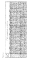
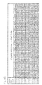
- Figs. 4A and 4B show an example of the control map.
- Fig. 4A is a diagram showing thresholds of the differences between the AD values of rotation angle sensor signals for the left and right electric motor units that operate normally with respect to steering angles for left turns or left cornering caused by operating the steering wheel in a counterclockwise direction as seen from a driver. The thresholds are set in accordance with vehicle speeds. In this example, values associated with the differences between the rotation angles are defined as thresholds of the differences between the rotation angles of the left and right electric motor units 6, 6 that operate normally.
- Fig. 4B is a diagram showing thresholds of the difference between the AD values of rotation angle sensor signals for the left and right electric motor units that operate normally with respect to steering angles for right turns or right cornering. The thresholds are set in accordance with vehicle speeds.
- a threshold which is a value obtained by subtracting the AD value of a rotation angle sensor signal obtained from the right-side electric motor unit that operates normally from the AD value of a rotation angle sensor signal obtained from the left-side electric motor unit that operates normally is represented as Data_ij in Figs. 4A and 4B .
- the thresholds are set in accordance with corresponding steering angles and a vehicle speeds.
- the thresholds are defined as appropriate, for example, by a test with an actual vehicle, simulation, or the like.
- vehicle speeds are set in 10 km/h increments
- steering angles are set in 0.5 ⁇ radian increments, but the present invention is not limited to this example.
- the abnormality determiner 11 shown in Fig. 2 determines an abnormality of either one or both of the electric motor units 6, when the difference between the AD value of a rotation angle sensor signal from the electric motor unit 6 that drives one of the wheels 2 and the AD value of a rotation angle sensor signal from the electric motor unit 6 that drives the other wheel 2 deviates from Data_ij stored in the control map 10a as a value in a normal state.
- the abnormality determiner 11 further compares the differences between the vehicle speed sensed by the vehicle speed sensor 9 and respective rotation speeds (described later) of the electric motor units 6, 6 of the pair of left and right wheels 2, 2 which are obtained on the basis of the rotation angles sensed by the respective rotation angle sensors 36, and determines an abnormality of one of the electric motor units 6 that has the rotation speed with a greater difference from the vehicle speed.
- the abnormality notifier 12 notifies the ECU 21 of the abnormality of the electric motor unit 6.
- Fig. 5 is a graph showing a change of the rotation angle of the electric motor unit in the motor abnormality detection apparatus during traveling (forward traveling) of the vehicle in a drive range.
- An analog signal from an electrical angle 360° of the rotation angle sensor 36 provided in the electric motor unit 6 is converted to an n-bit digital value, so that the electrical angle 360° is represented by an AD value of a rotation angle sensor signal.
- a rotation angle sensor 36 with a shaft angle multiplier of 4X when the motor rotor of the electric motor unit 6 makes one rotation (a mechanical angle of 360°), four sawtooth waves are outputted as a signal of the rotation angle sensor 36.
- One sawtooth wave represents a mechanical angle of 90°.
- the rotation speed or the number of revolutions (rpm) of the electric motor unit 6 can be calculated from an amount of change in the signal of the rotation angle sensor 36 during a given sampling time period. Specifically, when the rotation angle sensor 36 with a shaft angle multiplier of 4X is employed, a value obtained by dividing "60" by the sampling time period during which a rotation angle sensor signal is obtained is multiplied by the amount of change in the signal of the rotation angle sensor 36, and then the value then is divided by a value obtained by multiplying the upper limit by 4, whereby the rotation speed of the electric motor unit 6 can be calculated.
- Fig. 6 is a graph showing changes of the rotation angle of the electric motor unit in the motor abnormality detection apparatus with respect to different rotation speeds during traveling of the vehicle in the drive range.
- Fig. 6 represents changes of the AD values of the rotation angle sensor signals with respect to the rotation speeds, rot1, rot2 and rot3, wherein rot2 > rot1> rot3 is satisfied, when the rotation direction of the electric motor unit is the counterclockwise (CCW) direction as seen from the output shaft side.
- CCW counterclockwise
- Fig. 7 is a graph showing a change of the rotation angle of the electric motor unit in the motor abnormality detection apparatus during traveling (backward traveling) of the vehicle in a reverse range.
- Fig. 7 indicates a change of the AD value of the rotation angle sensor signal when the motor rotor of the electric motor unit rotates in a clockwise (CW) direction as seen from the output shaft side of the electric motor unit.
- the value of the rotation angle sensor decreases from an upper limit to 0, returns to the upper limit when reaching 0, and decreases again from the upper limit to 0, which is repeated.
- Fig. 8 is a graph showing changes of the rotation angle of the electric motor unit in the motor abnormality detection apparatus with respect to different rotation speeds during traveling of the vehicle in the reverse range.
- Fig. 8 represents changes of the AD values of the rotation angle sensor signals with respect to the rotation speeds, rot1, rot2, and rot3, wherein rot2 > rot1> rot3 is satisfied, when the rotation direction of the electric motor unit is the clockwise (CW) direction as seen from the output shaft side of the electric motor unit.
- the steering angle sensor 15b senses the steering angle of the vehicle
- the rotation angle sensors 36 sense the respective rotation angles of the electric motor units 6,
- the vehicle speed sensor 9 senses the vehicle speed.
- the abnormality determiner 11 determines an abnormality of either one or both of the electric motor units 6, when the difference between the AD value of the rotation angle sensor signal from the electric motor unit 6 that drives one wheel 2 and the AD value of the rotation angle sensor signal from the electric motor unit 6 that drives the other wheel 2 deviates from Data_ij stored in the control map 10a as a value in a normal state.
- the abnormality determiner 11 Upon determination of an abnormality of the electric motor units 6, the abnormality determiner 11 further compares the differences between the vehicle speed sensed by the vehicle speed sensor 9 and respective rotation speeds of the electric motor units 6, 6 of the pair of left and right wheels 2, 2 which are obtained on the basis of the rotation angles sensed by the rotation angle sensors 36, and determines the abnormality of one of the electric motor units 6 that has the rotation speed with a greater difference from the vehicle speed.
- the abnormality determiner 11 can accurately detect an abnormality of the electric motor units 6 regardless of the vehicle speed.
- rotation angles each of which takes into consideration a difference between rotations of the inner and outer wheels corresponding to the steering angle are set, so that it is possible to accurately perform a determination as to an abnormality of the electric motor units 6 even during non-straight traveling of the vehicle. Even when the voltage of the battery 19 drops, it is possible to accurately detect an abnormality of the electric motor units 6.
- the abnormality notifier 12 notifies the ECU 21 of an abnormality of the electric motor unit 6, and an abnormality display 13 of the ECU 21 sends notice of the abnormality of the electric motor unit 6 to a display device 14, thereby allowing driver's attention to be drawn to the abnormality.
- the driver can take necessary measures against the abnormality of the electric motor unit 6 early.
- the motor abnormality detection apparatus may be applied to a front-wheel drive electric vehicle which includes left and right front wheels as drive wheels and left and right rear wheels as driven wheels. Furthermore, the motor abnormality detection apparatus may be applied to a four-wheel drive electric vehicle which includes left and right front and rear wheels 3, 2 as drive wheels as in a second embodiment shown in Fig. 9 .
Landscapes
- Engineering & Computer Science (AREA)
- Power Engineering (AREA)
- Transportation (AREA)
- Mechanical Engineering (AREA)
- Life Sciences & Earth Sciences (AREA)
- Sustainable Development (AREA)
- Sustainable Energy (AREA)
- Electric Propulsion And Braking For Vehicles (AREA)
- Arrangement Or Mounting Of Propulsion Units For Vehicles (AREA)
Abstract
A motor abnormality detection apparatus for an electric vehicle is provided which is able to accurately detect an abnormality of electric motors and allows the cost to be reduced. The apparatus includes: a steering angle sensor (15b) sensing a steering angle of the vehicle; rotation angle sensors (36) sensing rotation angles of the respective motors (6); a vehicle speed sensor (9); a control map (10a) storing a relationship among a difference between rotation angles of the left and right motors (6, 6) operating normally, a steering angle, and a vehicle speed; and an abnormality determiner (11) determining the abnormality of the motor (6), when a difference between rotation angles of the sensed left and right motors (6, 6) deviates from the difference between the rotation angles retrieved from the map (10a) based on the sensed steering angle and the sensed vehicle speed.
Description
- This application is based on and claims Convention priority to Japanese patent application No.
2012-221070, filed October 3, 2012 - The present invention relates to a motor abnormality detection apparatus for an electric vehicle, and relates to a technique capable of accurately detecting an abnormality of a drive device.
- A control method and apparatus for an electric vehicle have been proposed which allow the vehicle to continue to travel, when an abnormality such as malfunction in a drive device or an electric motor unit in an in-wheel motor drive system for the electric vehicle occurs, by another electric motor unit (
Patent Documents 1 and 2). In an electric vehicle which includes a drive device independently driving at least left and right wheels and including an electric motor unit, when an abnormality of either one of the drive devices is occurs, a detector for detecting the abnormality of the drive device is meaningful. The detector will be described in the following 1 to 3. - 1. A torque command for a driving motor unit and a driving current supplied to the driving motor unit are compared. When the driving current indicates that it is abnormal with respect to the torque command, it is determined that an abnormality of the drive device has occurred.
- 2. A wheel speed of a wheel driven by the drive device and a vehicle speed or a wheel speed of another wheel that is laterally symmetric thereto are compared. When the wheel speed indicates that it is abnormal, it is determined that an abnormality of the drive device has occurred.
- 3. The drive device includes a torque sensor which senses driving torque at the driving motor unit. When output torque of the driving motor unit sensed by the torque sensor indicates that it is abnormal with respect to the torque command for the driving motor unit, it is determined that an abnormality of the drive motor unit has occurred.
- There is a method in which, when an abnormality of the electric motor is determined, steering assist torque is generated in a direction in which yaw moment generated with the abnormality of the electric motor unit is cancelled. In addition, for example, there is also a method in which yaw moment generated in the vehicle is reduced by decreasing a driving force of a driving motor unit on the same axle at the side laterally opposite to a side determined to have the abnormality, and a slip ratio of the tire is reduced by decreasing a driving force at the laterally opposite side, thereby ensuring a sufficient lateral frictional force generated in the tire.
-
- [Patent Document 1] JP Laid-open Patent Publication No.
2010-166740 - [Patent Document 2]
JP Laid-open Patent Publication No. 2006-333603 - The above-described detector for detecting an abnormality of the drive device has the following problems.
- 1. In order to detect an abnormality of the driving electric motor unit, the drive device needs a torque sensor which senses driving torque of the driving motor unit, and thus becomes expensive. In addition, due to a voltage drop of a battery, execution of control of a weak magnetic field in a high speed range, or the like, the torque command and the torque of the motor unit sensed by the torque sensor do not necessarily fall within a normal error range. Thus, an abnormality of the driving motor unit may be erroneously detected.
- 2. It is necessary to include a wheel speed sensor which allows the wheel speed of the wheel and the vehicle speed or the wheel speed of another wheel that is laterally symmetric thereto to be compared. This leads to an increase in the cost.
- An object of the present invention is to provide a motor abnormality detection apparatus for an electric vehicle which is able to accurately detect an abnormality of electric motor units in the electric vehicle and allows the cost to be reduced as compared to the conventional art. The general aspects of the present invention will now be described using the reference signs in the figures showing embodiments.
- A motor abnormality detection apparatus for an electric vehicle according to the present invention is a motor abnormality detection apparatus having a
drive device 8 including anelectric motor unit 6. The motor abnormality detection apparatus is configured to detect an abnormality of theelectric motor unit 6. Theelectric motor unit 6 includeselectric motor units right wheels steering angle sensor 15b configured to sense a steering angle of the vehicle;rotation angle sensors 36 configured to sense rotation angles of the respectiveelectric motor units 6; avehicle speed sensor 9 configured to sense a vehicle speed; acontrol map 10a configured to store a relationship among a value associated with a difference between rotation angles of the left and rightelectric motor units electric motor unit 6, when a difference between rotation angles of the left and rightelectric motor units rotation angle sensors 36 deviates from a value associated with the difference between the rotation angles which is retrieved from thecontrol map 10a based on the steering angle and the vehicle speed sensed by thesteering angle sensor 15b and thevehicle speed sensor 9, respectively. - According to this configuration, during traveling of the electric vehicle, the
steering angle sensor 15b senses the steering angle of the vehicle. Therotation angle sensors 36 sense the respective rotation angle of theelectric motor units 6. Thevehicle speed sensor 9 senses the vehicle speed. In thecontrol map 10a, the relationship among the value associated with the difference between the rotation angles of the left and rightelectric motor units control map 10a. In other words, in thecontrol map 10a, a rotation angle which takes into consideration a difference between rotations of the inner and outer wheels corresponding to the steering angle is set, so that it is possible to accurately perform a determination as to an abnormality of theelectric motor unit 6 even during non-straight traveling of the vehicle. - The abnormality determiner 11 determines that the
electric motor unit 6 is normal, when the difference between the actual rotation angles sensed by therotation angle sensors 36 falls within the value associated with the difference between the rotation angles which is retrieved from thecontrol map 10a based on the actual steering angle and the actual vehicle speed sensed by thesteering angle sensor 15b and thevehicle speed sensor 9, respectively. On the other hand, the abnormality determiner 11 determines an abnormality of theelectric motor units 6, when the difference between the actual rotation angles deviates from the value associated with the difference between the rotation angles which is retrieved from thecontrol map 10a. In this case, even when a voltage of abattery 19 drops, it is possible to accurately detect an abnormality of theelectric motor units 6. In addition, it is possible to detect an abnormality of theelectric motor units 6 without using an expensive torque sensor or the like, and thus the cost can be reduced as compared to the conventional art. When an abnormality of theelectric motor unit 6 is determined, for example, driver's attention is drawn to the abnormality of theelectric motor unit 6, so that the driver can take necessary measures against theelectric motor unit 6 early. - The
control map 10a may store, at intervals of a vehicle speed or in increments of a vehicle speed, a threshold of the difference between a rotation angle of theelectric motor unit 6 operating normally that drives either onewheel 2 of the left andright wheels electric motor unit 6 operating normally that drives theother wheel 2. In this example, the value associated with the difference between the rotation angles is defined as a threshold of the difference between the rotation angles of the left and rightelectric motor units electric motor units 6 regardless of the vehicle speed. - The abnormality determiner 11 may determine the abnormality of either one or both of the
electric motor units 6, when the difference between the rotation angle of theelectric motor unit 6 that drives the either onewheel 2 of the left andright wheels electric motor unit 6 that drives theother wheel 2 deviates from the threshold which is stored in thecontrol map 10a. - Upon determination of the abnormality of the
electric motor unit 6, the abnormality determiner 11 may further compare differences between the vehicle speed sensed by thevehicle speed sensor 9 and respective rotation speeds of theelectric motor units right wheels rotation angle sensors 36, and may determine the abnormality of one of theelectric motor units 6 that has the rotation speed with a greater difference from the vehicle speed. By identifying theelectric motor unit 6 determined to have the abnormality as described above, it is possible to continue to use theelectric motor unit 6 operating normally, and it is possible to repair or replace only theelectric motor unit 6 having the abnormality. Thus, man-hours for the repair or the replacement can be reduced. - The abnormality determiner 11 may determine the abnormality of the
electric motor unit 6 not only during forward traveling of the vehicle but also during backward traveling of the vehicle. It is possible to determine the abnormality of theelectric motor unit 6 during forward traveling of the vehicle as well as during backward traveling of the vehicle, and thus in addition to the effect that the abnormality of theelectric motor unit 6 can be detected early, the versatility as a motor abnormality detection apparatus increases. - The
electric motor unit 6 may drive either of or both front wheels andrear wheels electric motor unit 6 may be partially or entirely disposed within thewheel 2, and thedrive device 8 may form an in-wheel motor drive system which includes theelectric motor unit 6, awheel bearing unit 4, and areducer unit 7. - Any combination of at least two constructions, disclosed in the appended claims and/or the specification and/or the accompanying drawings should be construed as included within the scope of the present invention. In particular, any combination of two or more of the appended claims should be equally construed as included within the scope of the present invention.
- In any event, the present invention will become more clearly understood from the following description of preferred embodiments thereof, when taken in conjunction with the accompanying drawings. However, the embodiments and the drawings are given only for the purpose of illustration and explanation, and are not to be taken as limiting the scope of the present invention in any way whatsoever, which scope is to be determined by the appended claims. In the accompanying drawings, like reference numerals are used to denote like parts throughout the several views, and:
-
Fig. 1 is a block diagram of a schematic configuration showing an electric vehicle according to a first embodiment of the present invention in a plan view; -
Fig. 2 is a block diagram of a control system showing a motor abnormality detection apparatus of the electric vehicle; -
Fig. 3 is a circuit diagram of an inverter unit of the electric vehicle; -
Fig. 4A is a diagram showing an example of a control map of the motor abnormality detection apparatus; -
Fig. 4B is a diagram showing another example of the control map of the motor abnormality detection apparatus; -
Fig. 5 is a graph showing a change of a rotation angle of an electric motor unit in the motor abnormality detection apparatus during traveling of the vehicle in a drive range; -
Fig. 6 is a graph showing changes of the rotation angle of the electric motor unit in the motor abnormality detection apparatus with respect to different rotation speeds during traveling of the vehicle in the drive range; -
Fig. 7 is a graph showing a change of the rotation angle of the electric motor unit in the motor abnormality detection apparatus during traveling of the vehicle in a reverse range; -
Fig. 8 is a graph showing changes of the rotation angle of the electric motor unit in the motor abnormality detection apparatus with respect to different rotation speeds during traveling of the vehicle in the reverse range; and -
Fig. 9 is a plan view showing a schematic configuration of electric motor units of an electric vehicle according to a second embodiment of the present invention. - A motor abnormality detection apparatus for an electric vehicle according to a first embodiment of the present invention will be described with reference to
Figs. 1 to 8 .Fig. 1 is a block diagram of a schematic configuration showing an electric vehicle equipped with the motor abnormality detection apparatus according to the embodiment, in a plan view. The electric vehicle is a four-wheel vehicle that includes avehicle body 1 with left and rightrear wheels 2 and left and rightfront wheels 3, with therear wheels 2 being drive wheels and thefront wheels 3 being driven wheels. Thefront wheels 3 are steered wheels. The electric vehicle of this example includesdrive devices right wheels electric motor units electric motor unit 6 is transmitted via areducer unit 7 and awheel bearing unit 4 to thewheel 2. Theelectric motor unit 6 of eachdrive device 8 is partly or entirely disposed within thewheel 2, and eachdrive device 8 forms an in-wheel motor drive system which includes theelectric motor unit 6, thereducer unit 7, and thewheel bearing unit 4. Each of thewheels - A control system will be described. As shown in
Fig. 1 , thevehicle body 1 is equipped with amotor drive system 20 which includes anECU 21 and a plurality ofinverter units 22. TheECU 21 is primary control means configured to perform general integrated control of the vehicle and send a command to eachinverter unit 22. Eachinverter unit 22 is configured to perform control of each tractionelectric motor unit 6 according to a command from theECU 21. TheECU 21 includes a computer, programs that may be executed by the computer, and various electronic circuits. A common computer or electrical circuitries on a common board may form light current systems for theECU 21 and theinverter units 22. - The
ECU 21 includes atorque allocator 48. Thetorque allocator 48 is configured to generate an accelerating/decelerating command in the form of a torque value, which will influence theelectric motor units accelerator manipulation unit 16, a decelerating command outputted from abrake manipulation unit 17, and a cornering command outputted from asteering device 15, and to send the accelerating/decelerating command to theinverter units 22. Thetorque allocator 48 is configured to, in response to a decelerating command outputted from thebrake manipulation unit 17, generate a braking torque command allocated to regenerative braking of theelectric motor unit 6 and a braking torque command allocated to the operation of the brakes which are not shown. Such a braking torque command allocated to regenerative braking is reflected in a torque command value that serves as the aforementioned accelerating/decelerating command that is supplied to the respective tractionelectric motor units - The
accelerator manipulation unit 16 includes an accelerator pedal and a sensor configured to sense the depression of the accelerator pedal. Thebrake manipulation unit 17 includes a brake pedal and a sensor configured to sense the depression of the brake pedal. Thesteering device 15 includes asteering wheel 15a and asteering angle sensor 15b configured to sense a steering angle which is a rotation angle of thesteering wheel 15a. Abattery 19 is mounted on thevehicle body 1 and is used for driving theelectric motor units 6 and as a power source for an entire electrical system of the vehicle. - As shown in
Fig. 2 , eachinverter unit 22 includes: apower circuitry 28 provided for eachelectric motor unit 6; and amotor control circuitry 29 configured to control thepower circuitry 28. A commonmotor control circuitry 29 may be provided fordifferent power circuitries 28. Independentmotor control circuitries 29 may be provided for respectivedifferent power circuitries 28. Themotor control circuitry 29 is configured to send various information related to the in-wheel motor drive system held by themotor control circuitry 29, such as a variety of detected values or various control values, to theECU 21. Thepower circuitry 28 includes aninverter 31 and aPWM driver 32 configured to drive theinverter 31. Theinverter 31 is configured to convert a DC power from thebattery 19 into a three-phase AC power used to drive theelectric motor unit 6. - As shown in
Fig. 3 , eachelectric motor unit 6 includes a three-phase synchronous motor such as an IPM (Interior Permanent Magnet) synchronous motor. Theinverter 31 includes a plurality of drivingelements 31a and is configured to produce driving voltage pulses for the corresponding three phases (U phase, V phase, and W phase) of theelectric motor unit 6. As each drivingelement 31a, a semiconductor switching element is used. Amotor drive controller 37 is configured to perform pulse width modulation based on a received current command to generate ON/OFF commands to thePWM driver 32, and thePWM driver 32 drives the drivingelements 31a. - The
PWM driver 32, which serves as a light current circuit segment in thepower circuitry 28, and themotor control circuitry 29 form acomputation segment 33 which serves as a light current circuit segment in theinverter unit 22. Thecomputation segment 33 includes a computer, programs that may be executed by the computer, and electronic circuits. In addition, for example, a smoothingsegment 34, which includes a smoothing capacitor, is also provided in theinverter unit 22 so as to be interposed in parallel between thebattery 19 and theinverter 31. - Each
electric motor unit 6 includes arotation angle sensor 36 configured to sense a rotation angle of a motor rotor. In order to maximize the efficiency of theelectric motor unit 6, on the basis of a relative rotation angle between a motor stator and the motor rotor which is sensed by therotation angle sensor 36, themotor drive controller 37 of themotor control circuitry 29 is configured to control timings at which respective phase alternating currents are supplied to coils of the stator. - As shown in
Fig. 2 , the electric vehicle is equipped with the motor abnormality detection apparatus configured to detect an abnormality of theelectric motor units 6. The motor abnormality detection apparatus includes thesteering angle sensor 15b, therotation angle sensor 36, avehicle speed sensor 9 configured to sense a vehicle speed, astorage unit 10,abnormality determiner 11, andabnormality notifier 12. Theabnormality determiner 11 and theabnormality notifier 12 are provided in themotor control circuitry 29 configured as described above. Thestorage unit 10 is provided in a storage area in theECU 21. Thestorage unit 10 includes acontrol map 10a (described later) which stores a relationship among a value associated with a difference in rotation angle, a steering angle, and a vehicle speed (a travel speed of the vehicle). Themap 10a can be updated. Alternatively, the control map may be provided in a storage area in themotor control circuitry 29. - The
abnormality determiner 11 is configured to determine an abnormality of theelectric motor units 6, when the difference between the rotation angles of the left and rightelectric motor units rotation angle sensors 36, that is, the difference between AD values of left and right rotation angle sensor signals deviates from a value associated with the difference between the rotation angles which is retrieved from thecontrol map 10a based on the steering angle and the vehicle speed sensed by thesteering angle sensor 15b and thevehicle speed sensor 9, respectively. The word "AD value" refers to a value obtained by converting an analog value of the rotation angle sensor signal to a digital value. Theabnormality determiner 11 determines an abnormality of theelectric motor units 6 not only during forward traveling of the vehicle but also during backward traveling of the vehicle. -
Figs. 4A and4B show an example of the control map.Fig. 4A is a diagram showing thresholds of the differences between the AD values of rotation angle sensor signals for the left and right electric motor units that operate normally with respect to steering angles for left turns or left cornering caused by operating the steering wheel in a counterclockwise direction as seen from a driver. The thresholds are set in accordance with vehicle speeds. In this example, values associated with the differences between the rotation angles are defined as thresholds of the differences between the rotation angles of the left and rightelectric motor units Fig. 4B is a diagram showing thresholds of the difference between the AD values of rotation angle sensor signals for the left and right electric motor units that operate normally with respect to steering angles for right turns or right cornering. The thresholds are set in accordance with vehicle speeds. - A threshold which is a value obtained by subtracting the AD value of a rotation angle sensor signal obtained from the right-side electric motor unit that operates normally from the AD value of a rotation angle sensor signal obtained from the left-side electric motor unit that operates normally is represented as Data_ij in
Figs. 4A and4B . The thresholds are set in accordance with corresponding steering angles and a vehicle speeds. The thresholds are defined as appropriate, for example, by a test with an actual vehicle, simulation, or the like. InFigs. 4A and4B , vehicle speeds are set in 10 km/h increments, and steering angles are set in 0.5π radian increments, but the present invention is not limited to this example. - The
abnormality determiner 11 shown inFig. 2 determines an abnormality of either one or both of theelectric motor units 6, when the difference between the AD value of a rotation angle sensor signal from theelectric motor unit 6 that drives one of thewheels 2 and the AD value of a rotation angle sensor signal from theelectric motor unit 6 that drives theother wheel 2 deviates from Data_ij stored in thecontrol map 10a as a value in a normal state. Next, upon determination of an abnormality of theelectric motor units 6, theabnormality determiner 11 further compares the differences between the vehicle speed sensed by thevehicle speed sensor 9 and respective rotation speeds (described later) of theelectric motor units right wheels rotation angle sensors 36, and determines an abnormality of one of theelectric motor units 6 that has the rotation speed with a greater difference from the vehicle speed. When theabnormality determiner 11 determines an abnormality of theelectric motor unit 6, theabnormality notifier 12 notifies theECU 21 of the abnormality of theelectric motor unit 6. -
Fig. 5 is a graph showing a change of the rotation angle of the electric motor unit in the motor abnormality detection apparatus during traveling (forward traveling) of the vehicle in a drive range. A description will be given also with reference toFig. 2 . An analog signal from an electrical angle 360° of therotation angle sensor 36 provided in theelectric motor unit 6 is converted to an n-bit digital value, so that the electrical angle 360° is represented by an AD value of a rotation angle sensor signal. For example, in the case where arotation angle sensor 36 with a shaft angle multiplier of 4X is used, when the motor rotor of theelectric motor unit 6 makes one rotation (a mechanical angle of 360°), four sawtooth waves are outputted as a signal of therotation angle sensor 36. One sawtooth wave represents a mechanical angle of 90°. When the motor rotor of theelectric motor unit 6 is rotated in a counterclockwise (CCW) direction as seen from the output shaft side of theelectric motor unit 6, the value of therotation angle sensor 36 increases from 0 to an upper limit, returns to 0 when reaching the upper limit, and increases again from 0 to the upper limit, which is repeated. - The rotation speed or the number of revolutions (rpm) of the
electric motor unit 6 can be calculated from an amount of change in the signal of therotation angle sensor 36 during a given sampling time period. Specifically, when therotation angle sensor 36 with a shaft angle multiplier of 4X is employed, a value obtained by dividing "60" by the sampling time period during which a rotation angle sensor signal is obtained is multiplied by the amount of change in the signal of therotation angle sensor 36, and then the value then is divided by a value obtained by multiplying the upper limit by 4, whereby the rotation speed of theelectric motor unit 6 can be calculated. -
Fig. 6 is a graph showing changes of the rotation angle of the electric motor unit in the motor abnormality detection apparatus with respect to different rotation speeds during traveling of the vehicle in the drive range.Fig. 6 represents changes of the AD values of the rotation angle sensor signals with respect to the rotation speeds, rot1, rot2 and rot3, wherein rot2 > rot1> rot3 is satisfied, when the rotation direction of the electric motor unit is the counterclockwise (CCW) direction as seen from the output shaft side. The higher the rotation speed of the electric motor unit is, the larger the number of sawtooth waves outputted from the rotation angle sensor within a given time period is. -
Fig. 7 is a graph showing a change of the rotation angle of the electric motor unit in the motor abnormality detection apparatus during traveling (backward traveling) of the vehicle in a reverse range.Fig. 7 indicates a change of the AD value of the rotation angle sensor signal when the motor rotor of the electric motor unit rotates in a clockwise (CW) direction as seen from the output shaft side of the electric motor unit. The value of the rotation angle sensor decreases from an upper limit to 0, returns to the upper limit when reaching 0, and decreases again from the upper limit to 0, which is repeated. -
Fig. 8 is a graph showing changes of the rotation angle of the electric motor unit in the motor abnormality detection apparatus with respect to different rotation speeds during traveling of the vehicle in the reverse range.Fig. 8 represents changes of the AD values of the rotation angle sensor signals with respect to the rotation speeds, rot1, rot2, and rot3, wherein rot2 > rot1> rot3 is satisfied, when the rotation direction of the electric motor unit is the clockwise (CW) direction as seen from the output shaft side of the electric motor unit. - Advantageous effects will be described. During traveling of the electric vehicle, as shown in
Fig. 2 , thesteering angle sensor 15b senses the steering angle of the vehicle, therotation angle sensors 36 sense the respective rotation angles of theelectric motor units 6, and thevehicle speed sensor 9 senses the vehicle speed. Theabnormality determiner 11 determines an abnormality of either one or both of theelectric motor units 6, when the difference between the AD value of the rotation angle sensor signal from theelectric motor unit 6 that drives onewheel 2 and the AD value of the rotation angle sensor signal from theelectric motor unit 6 that drives theother wheel 2 deviates from Data_ij stored in thecontrol map 10a as a value in a normal state. - Upon determination of an abnormality of the
electric motor units 6, theabnormality determiner 11 further compares the differences between the vehicle speed sensed by thevehicle speed sensor 9 and respective rotation speeds of theelectric motor units right wheels rotation angle sensors 36, and determines the abnormality of one of theelectric motor units 6 that has the rotation speed with a greater difference from the vehicle speed. By identifying theelectric motor unit 6 determined to have the abnormality as described above, it is possible to continue to use theelectric motor unit 6 operating normally, and it is possible to repair or replace only theelectric motor unit 6 having the abnormality. Thus, man-hours for the repair or the replacement can be reduced. - By setting the thresholds (Data_ij) of the differences between the left and right rotation angles at short vehicle speed intervals in the
control map 10a, theabnormality determiner 11 can accurately detect an abnormality of theelectric motor units 6 regardless of the vehicle speed. In thecontrol map 10a, rotation angles each of which takes into consideration a difference between rotations of the inner and outer wheels corresponding to the steering angle are set, so that it is possible to accurately perform a determination as to an abnormality of theelectric motor units 6 even during non-straight traveling of the vehicle. Even when the voltage of thebattery 19 drops, it is possible to accurately detect an abnormality of theelectric motor units 6. In addition, it is possible to detect an abnormality of theelectric motor units 6 without using an expensive torque sensor or the like, and thus the cost can be reduced as compared to the conventional art. Moreover, theabnormality notifier 12 notifies theECU 21 of an abnormality of theelectric motor unit 6, and anabnormality display 13 of theECU 21 sends notice of the abnormality of theelectric motor unit 6 to adisplay device 14, thereby allowing driver's attention to be drawn to the abnormality. Thus, the driver can take necessary measures against the abnormality of theelectric motor unit 6 early. - In the above embodiment, the rear-wheel drive electric vehicle has been described, but the motor abnormality detection apparatus may be applied to a front-wheel drive electric vehicle which includes left and right front wheels as drive wheels and left and right rear wheels as driven wheels. Furthermore, the motor abnormality detection apparatus may be applied to a four-wheel drive electric vehicle which includes left and right front and
rear wheels Fig. 9 . - Although the preferred embodiments and application embodiments have been described with reference to the accompanying drawings as presented above, those skilled in the art will readily conceive numerous changes and modifications within the framework of obviousness upon the reading of the specification herein presented of the present invention. Accordingly, such changes and modifications are to be construed as included in the scope of the present invention as delivered from the claims annexed hereto.
-
- 2,3
- wheel
- 6
- electric motor unit
- 8
- drive device
- 9
- vehicle speed sensor
- 10a
- control map
- 11
- abnormality determiner
- 15b
- steering angle sensor
- 36
- rotation angle sensor
Claims (7)
- A motor abnormality detection apparatus for an electric vehicle comprising a drive device including an electric motor unit, the motor abnormality detection apparatus being configured to detect an abnormality of the electric motor unit, the electric motor unit comprising electric motor units which independently drive at least left and right wheels, respectively, the motor abnormality detection apparatus comprising:a steering angle sensor configured to sense a steering angle of the vehicle;rotation angle sensors configured to sense rotation angles of the respective electric motor units;a vehicle speed sensor configured to sense a vehicle speed;a control map configured to store a relationship among a value associated with a difference between rotation angles of the left and right electric motor units that operate normally, a steering angle, and a vehicle speed; andan abnormality determiner configured to determine the abnormality of the electric motor unit, when a difference between rotation angles of the left and right electric motor units which are sensed by the respective rotation angle sensors deviates from the value associated with the difference between the rotation angles which is retrieved from the control map based on the steering angle and the vehicle speed sensed by the steering angle sensor and the vehicle speed sensor, respectively.
- The motor abnormality detection apparatus for the electric vehicle as claimed in claim 1, wherein the control map stores, at intervals of a vehicle speed, a threshold of the difference between a rotation angle of the electric motor unit operating normally that drives either one wheel of the left and right wheels and a rotation angle of the electric motor unit operating normally that drives the other wheel.
- The motor abnormality detection apparatus for the electric vehicle as claimed in claim 2, wherein the abnormality determiner determines the abnormality of either one or both of the electric motor units, when the difference between the rotation angle of the electric motor unit that drives the either one wheel of the left and right wheels and the rotation angle of the electric motor unit that drives the other wheel deviates from the threshold stored in the control map.
- The motor abnormality detection apparatus for the electric vehicle as claimed in claim 2 or 3, wherein upon determination of the abnormality of the electric motor unit, the abnormality determiner further compares differences between the vehicle speed sensed by the vehicle speed sensor and respective rotation speeds of the electric motor units of the left and right wheels which are obtained on the basis of the rotation angles sensed by the rotation angle sensors, and determines the abnormality of one of the electric motor units that has the rotation speed with a greater difference from the vehicle speed.
- The motor abnormality detection apparatus for the electric vehicle as claimed in any one of claims 1 to 4, wherein the abnormality determiner determines the abnormality of the electric motor unit not only during forward traveling of the vehicle but also during backward traveling of the vehicle.
- The motor abnormality detection apparatus for the electric vehicle as claimed in any one of claims 1 to 5, wherein the electric motor unit drives either of or both front wheels and rear wheels of the vehicle.
- The motor abnormality detection apparatus for the electric vehicle as claimed in any one of claims 1 to 6, wherein the electric motor unit is partially or entirely disposed within the wheel, and the drive device forms an in-wheel motor drive system which includes the electric motor unit, a wheel bearing unit, and a reducer unit.
Applications Claiming Priority (2)
| Application Number | Priority Date | Filing Date | Title |
|---|---|---|---|
| JP2012221070A JP2014075868A (en) | 2012-10-03 | 2012-10-03 | Motor abnormality detection device of electric vehicle |
| PCT/JP2013/075653 WO2014054454A1 (en) | 2012-10-03 | 2013-09-24 | Motor fault detection device for electric automobile |
Publications (1)
| Publication Number | Publication Date |
|---|---|
| EP2905165A1 true EP2905165A1 (en) | 2015-08-12 |
Family
ID=50434783
Family Applications (1)
| Application Number | Title | Priority Date | Filing Date |
|---|---|---|---|
| EP13844458.3A Withdrawn EP2905165A1 (en) | 2012-10-03 | 2013-09-24 | Motor fault detection device for electric automobile |
Country Status (6)
| Country | Link |
|---|---|
| US (1) | US20150202963A1 (en) |
| EP (1) | EP2905165A1 (en) |
| JP (1) | JP2014075868A (en) |
| CN (1) | CN104684752A (en) |
| IN (1) | IN2015DN02689A (en) |
| WO (1) | WO2014054454A1 (en) |
Cited By (1)
| Publication number | Priority date | Publication date | Assignee | Title |
|---|---|---|---|---|
| US12054376B2 (en) | 2019-10-10 | 2024-08-06 | Mitsubishi Logisnext Europe Oy | Control of drive of a lift truck |
Families Citing this family (12)
| Publication number | Priority date | Publication date | Assignee | Title |
|---|---|---|---|---|
| US10439538B2 (en) * | 2016-04-29 | 2019-10-08 | Deere & Company | Method and system for estimating a rotor position with a notch filter |
| JP2018098868A (en) * | 2016-12-12 | 2018-06-21 | Ntn株式会社 | Vehicle control device |
| JP6457589B2 (en) * | 2017-06-23 | 2019-01-23 | ファナック株式会社 | Abnormality diagnosis apparatus and abnormality diagnosis method |
| JP6380628B1 (en) * | 2017-07-31 | 2018-08-29 | 株式会社安川電機 | Power conversion apparatus, server, and data generation method |
| CN111491821B (en) * | 2017-12-18 | 2023-07-21 | Ntn株式会社 | Drive control devices for motor vehicles |
| CN110062410B (en) * | 2019-03-28 | 2021-09-28 | 东南大学 | Cell interruption detection positioning method based on self-adaptive resonance theory |
| KR102791576B1 (en) * | 2020-08-24 | 2025-04-04 | 현대자동차주식회사 | Driving stabilization method for wheel motor driven vehicle |
| JP7447831B2 (en) * | 2021-01-18 | 2024-03-12 | 株式会社デンソー | Vehicle control device, program, control method |
| KR20220121284A (en) | 2021-02-24 | 2022-09-01 | 현대자동차주식회사 | Vehicle drivetrain hardware damage diagnosis device and method |
| US20240124000A1 (en) * | 2022-10-18 | 2024-04-18 | Robert Bosch Gmbh | Detection and compensation of wheel speed sensor failure |
| KR102762991B1 (en) * | 2022-11-18 | 2025-02-05 | 주식회사 현대케피코 | Method for Control Dual In-wheel Motor type Electric Two-wheeled Vehicle |
| US12522083B1 (en) * | 2024-08-27 | 2026-01-13 | GM Global Technology Operations LLC | Emulating handling characteristics with an electric vehicle |
Family Cites Families (15)
| Publication number | Priority date | Publication date | Assignee | Title |
|---|---|---|---|---|
| JP2005168184A (en) * | 2003-12-03 | 2005-06-23 | Toyota Motor Corp | Motor performance degradation determination device for motor-driven vehicle |
| JP4776981B2 (en) * | 2005-05-25 | 2011-09-21 | 株式会社クリーンクラフト | Electric vehicle drive control device |
| DE102005025287A1 (en) * | 2005-06-02 | 2006-12-07 | Continental Teves Ag & Co. Ohg | Driving condition adapted, based on steering intervention driving dynamics control |
| DE602006016865D1 (en) * | 2005-12-27 | 2010-10-21 | Honda Motor Co Ltd | VEHICLE CONTROL DEVICE |
| EP2026458A1 (en) * | 2006-05-31 | 2009-02-18 | NSK Ltd. | Electric power steering device |
| JP2008068777A (en) * | 2006-09-15 | 2008-03-27 | Toyota Motor Corp | Electric power steering device |
| JP5088530B2 (en) * | 2006-11-17 | 2012-12-05 | 株式会社ジェイテクト | Vehicle steering system |
| JP4495739B2 (en) * | 2007-02-16 | 2010-07-07 | 本田技研工業株式会社 | Steering system |
| JP2009006923A (en) * | 2007-06-29 | 2009-01-15 | Toyota Motor Corp | Vehicle steering device |
| JP2010166740A (en) | 2009-01-17 | 2010-07-29 | Nissan Motor Co Ltd | Control device for electric vehicle |
| US8423257B2 (en) * | 2010-03-17 | 2013-04-16 | Honda Motor Co., Ltd. | System for and method of maintaining a driver intended path |
| JP5527081B2 (en) * | 2010-07-23 | 2014-06-18 | 日産自動車株式会社 | Driving force estimation device for electric vehicle |
| JP5703618B2 (en) * | 2010-07-23 | 2015-04-22 | 日産自動車株式会社 | Torque abnormality determination device for electric vehicle |
| CN103298686B (en) * | 2011-01-07 | 2016-02-17 | 本田技研工业株式会社 | Electric power-assisted steering apparatus |
| KR101285464B1 (en) * | 2011-06-28 | 2013-07-12 | 주식회사 만도 | Steering angle sensor fail dection system |
-
2012
- 2012-10-03 JP JP2012221070A patent/JP2014075868A/en active Pending
-
2013
- 2013-09-24 CN CN201380051789.7A patent/CN104684752A/en active Pending
- 2013-09-24 WO PCT/JP2013/075653 patent/WO2014054454A1/en not_active Ceased
- 2013-09-24 EP EP13844458.3A patent/EP2905165A1/en not_active Withdrawn
-
2015
- 2015-03-31 US US14/674,340 patent/US20150202963A1/en not_active Abandoned
- 2015-04-01 IN IN2689DEN2015 patent/IN2015DN02689A/en unknown
Non-Patent Citations (1)
| Title |
|---|
| See references of WO2014054454A1 * |
Cited By (1)
| Publication number | Priority date | Publication date | Assignee | Title |
|---|---|---|---|---|
| US12054376B2 (en) | 2019-10-10 | 2024-08-06 | Mitsubishi Logisnext Europe Oy | Control of drive of a lift truck |
Also Published As
| Publication number | Publication date |
|---|---|
| IN2015DN02689A (en) | 2015-09-04 |
| US20150202963A1 (en) | 2015-07-23 |
| CN104684752A (en) | 2015-06-03 |
| WO2014054454A1 (en) | 2014-04-10 |
| JP2014075868A (en) | 2014-04-24 |
Similar Documents
| Publication | Publication Date | Title |
|---|---|---|
| EP2905165A1 (en) | Motor fault detection device for electric automobile | |
| EP2728736B1 (en) | Motor drive device | |
| CN103415992B (en) | Electric automobile | |
| US9114711B2 (en) | Electric vehicle | |
| CN103442931B (en) | Motor drive | |
| EP2679433B1 (en) | Electric automobile | |
| JP5832868B2 (en) | Electric car | |
| EP2783906A1 (en) | Electric vehicle control device | |
| JP5702237B2 (en) | Motor drive device | |
| WO2012121197A1 (en) | Electric vehicle | |
| US9692345B2 (en) | Motor drive device | |
| US12479314B2 (en) | Vehicle | |
| CN103947100A (en) | Motor control device for electric automobile | |
| CN109327166B (en) | System and method for operating a motor with a single motor position signal | |
| EP3010140A1 (en) | Electric-vehicle control device | |
| US12522238B2 (en) | Vehicle and method of controlling the same | |
| JP2013017352A (en) | Motor drive device | |
| JP5785004B2 (en) | Motor drive device | |
| CN103404023A (en) | Electric automobile | |
| JP2002136171A (en) | Control method for main shaft motor of hybrid car and the hybrid car | |
| JP6087399B2 (en) | Motor drive device | |
| JP5985724B2 (en) | Electric car | |
| JP2019118190A (en) | Abnormality diagnosis device for inverter, inverter device and electric vehicle with the inverter device mounted thereon |
Legal Events
| Date | Code | Title | Description |
|---|---|---|---|
| PUAI | Public reference made under article 153(3) epc to a published international application that has entered the european phase |
Free format text: ORIGINAL CODE: 0009012 |
|
| 17P | Request for examination filed |
Effective date: 20150327 |
|
| AK | Designated contracting states |
Kind code of ref document: A1 Designated state(s): AL AT BE BG CH CY CZ DE DK EE ES FI FR GB GR HR HU IE IS IT LI LT LU LV MC MK MT NL NO PL PT RO RS SE SI SK SM TR |
|
| AX | Request for extension of the european patent |
Extension state: BA ME |
|
| DAX | Request for extension of the european patent (deleted) | ||
| STAA | Information on the status of an ep patent application or granted ep patent |
Free format text: STATUS: THE APPLICATION IS DEEMED TO BE WITHDRAWN |
|
| 18D | Application deemed to be withdrawn |
Effective date: 20160401 |