EP2905037B1 - Dispositifs pour l'application d'un traitement par pression négative sur des plaies d'incision fermées - Google Patents
Dispositifs pour l'application d'un traitement par pression négative sur des plaies d'incision fermées Download PDFInfo
- Publication number
- EP2905037B1 EP2905037B1 EP14188893.3A EP14188893A EP2905037B1 EP 2905037 B1 EP2905037 B1 EP 2905037B1 EP 14188893 A EP14188893 A EP 14188893A EP 2905037 B1 EP2905037 B1 EP 2905037B1
- Authority
- EP
- European Patent Office
- Prior art keywords
- collection chamber
- sealant layer
- flexible sealant
- wound
- sealant structure
- Prior art date
- Legal status (The legal status is an assumption and is not a legal conclusion. Google has not performed a legal analysis and makes no representation as to the accuracy of the status listed.)
- Active
Links
- 238000009581 negative-pressure wound therapy Methods 0.000 title description 2
- 239000000565 sealant Substances 0.000 claims description 240
- 206010052428 Wound Diseases 0.000 claims description 131
- 208000027418 Wounds and injury Diseases 0.000 claims description 129
- 208000014674 injury Diseases 0.000 claims description 105
- 230000008733 trauma Effects 0.000 claims description 105
- 230000002829 reductive effect Effects 0.000 claims description 51
- 238000004891 communication Methods 0.000 claims description 42
- 230000000670 limiting effect Effects 0.000 claims description 25
- 239000000853 adhesive Substances 0.000 claims description 18
- 230000001070 adhesive effect Effects 0.000 claims description 18
- 230000007704 transition Effects 0.000 claims description 4
- 239000010410 layer Substances 0.000 description 274
- 210000003491 skin Anatomy 0.000 description 131
- 238000002560 therapeutic procedure Methods 0.000 description 52
- 239000012530 fluid Substances 0.000 description 43
- 210000001519 tissue Anatomy 0.000 description 29
- 208000002847 Surgical Wound Diseases 0.000 description 28
- 239000000463 material Substances 0.000 description 27
- 239000011241 protective layer Substances 0.000 description 25
- 230000035882 stress Effects 0.000 description 25
- 238000000034 method Methods 0.000 description 22
- 230000007246 mechanism Effects 0.000 description 19
- 238000007789 sealing Methods 0.000 description 12
- 230000009977 dual effect Effects 0.000 description 11
- 230000035876 healing Effects 0.000 description 11
- 239000003795 chemical substances by application Substances 0.000 description 10
- 230000008602 contraction Effects 0.000 description 9
- 230000000295 complement effect Effects 0.000 description 8
- 230000033001 locomotion Effects 0.000 description 8
- 230000006835 compression Effects 0.000 description 7
- 238000007906 compression Methods 0.000 description 7
- 239000006260 foam Substances 0.000 description 7
- 238000000926 separation method Methods 0.000 description 7
- 206010048038 Wound infection Diseases 0.000 description 6
- 230000008878 coupling Effects 0.000 description 6
- 238000010168 coupling process Methods 0.000 description 6
- 238000005859 coupling reaction Methods 0.000 description 6
- 238000005520 cutting process Methods 0.000 description 6
- 210000000416 exudates and transudate Anatomy 0.000 description 6
- 230000001105 regulatory effect Effects 0.000 description 6
- 239000003242 anti bacterial agent Substances 0.000 description 5
- 229940088710 antibiotic agent Drugs 0.000 description 5
- 239000004599 antimicrobial Substances 0.000 description 5
- 238000006073 displacement reaction Methods 0.000 description 5
- 230000002745 absorbent Effects 0.000 description 4
- 239000002250 absorbent Substances 0.000 description 4
- 238000009826 distribution Methods 0.000 description 4
- 230000004044 response Effects 0.000 description 4
- 230000000007 visual effect Effects 0.000 description 4
- 239000011324 bead Substances 0.000 description 3
- 230000015572 biosynthetic process Effects 0.000 description 3
- 239000011248 coating agent Substances 0.000 description 3
- 238000000576 coating method Methods 0.000 description 3
- 229940124447 delivery agent Drugs 0.000 description 3
- 230000000694 effects Effects 0.000 description 3
- 239000003292 glue Substances 0.000 description 3
- 239000000416 hydrocolloid Substances 0.000 description 3
- 208000015181 infectious disease Diseases 0.000 description 3
- 230000036961 partial effect Effects 0.000 description 3
- 230000009467 reduction Effects 0.000 description 3
- 230000037390 scarring Effects 0.000 description 3
- 238000004513 sizing Methods 0.000 description 3
- 230000003068 static effect Effects 0.000 description 3
- 230000029663 wound healing Effects 0.000 description 3
- 241000894006 Bacteria Species 0.000 description 2
- GHXZTYHSJHQHIJ-UHFFFAOYSA-N Chlorhexidine Chemical compound C=1C=C(Cl)C=CC=1NC(N)=NC(N)=NCCCCCCN=C(N)N=C(N)NC1=CC=C(Cl)C=C1 GHXZTYHSJHQHIJ-UHFFFAOYSA-N 0.000 description 2
- 208000034693 Laceration Diseases 0.000 description 2
- 206010030113 Oedema Diseases 0.000 description 2
- 230000003213 activating effect Effects 0.000 description 2
- 230000008859 change Effects 0.000 description 2
- 229960003260 chlorhexidine Drugs 0.000 description 2
- 238000013461 design Methods 0.000 description 2
- 239000003814 drug Substances 0.000 description 2
- 230000002500 effect on skin Effects 0.000 description 2
- 239000013013 elastic material Substances 0.000 description 2
- 230000005484 gravity Effects 0.000 description 2
- 239000011159 matrix material Substances 0.000 description 2
- 230000002093 peripheral effect Effects 0.000 description 2
- 239000004033 plastic Substances 0.000 description 2
- 229940124597 therapeutic agent Drugs 0.000 description 2
- 229910001316 Ag alloy Inorganic materials 0.000 description 1
- 229920000742 Cotton Polymers 0.000 description 1
- 206010051425 Enterocutaneous fistula Diseases 0.000 description 1
- JOYRKODLDBILNP-UHFFFAOYSA-N Ethyl urethane Chemical compound CCOC(N)=O JOYRKODLDBILNP-UHFFFAOYSA-N 0.000 description 1
- 206010061218 Inflammation Diseases 0.000 description 1
- 208000008081 Intestinal Fistula Diseases 0.000 description 1
- 206010033799 Paralysis Diseases 0.000 description 1
- 241000405070 Percophidae Species 0.000 description 1
- 206010036410 Postoperative wound infection Diseases 0.000 description 1
- 239000004820 Pressure-sensitive adhesive Substances 0.000 description 1
- BQCADISMDOOEFD-UHFFFAOYSA-N Silver Chemical compound [Ag] BQCADISMDOOEFD-UHFFFAOYSA-N 0.000 description 1
- 208000031650 Surgical Wound Infection Diseases 0.000 description 1
- 206010048031 Wound dehiscence Diseases 0.000 description 1
- 238000012084 abdominal surgery Methods 0.000 description 1
- 230000009471 action Effects 0.000 description 1
- 239000012790 adhesive layer Substances 0.000 description 1
- 239000002260 anti-inflammatory agent Substances 0.000 description 1
- 229940121363 anti-inflammatory agent Drugs 0.000 description 1
- 239000012298 atmosphere Substances 0.000 description 1
- QVGXLLKOCUKJST-UHFFFAOYSA-N atomic oxygen Chemical compound [O] QVGXLLKOCUKJST-UHFFFAOYSA-N 0.000 description 1
- 230000003190 augmentative effect Effects 0.000 description 1
- 230000001580 bacterial effect Effects 0.000 description 1
- 238000005452 bending Methods 0.000 description 1
- 230000008901 benefit Effects 0.000 description 1
- 230000003115 biocidal effect Effects 0.000 description 1
- 239000000560 biocompatible material Substances 0.000 description 1
- 239000003124 biologic agent Substances 0.000 description 1
- 230000017531 blood circulation Effects 0.000 description 1
- 230000012292 cell migration Effects 0.000 description 1
- 210000002808 connective tissue Anatomy 0.000 description 1
- 239000002537 cosmetic Substances 0.000 description 1
- 230000023753 dehiscence Effects 0.000 description 1
- 230000003111 delayed effect Effects 0.000 description 1
- 239000013536 elastomeric material Substances 0.000 description 1
- 230000003898 enterocutaneous fistula Effects 0.000 description 1
- 230000006355 external stress Effects 0.000 description 1
- 239000003102 growth factor Substances 0.000 description 1
- 238000003306 harvesting Methods 0.000 description 1
- 210000002865 immune cell Anatomy 0.000 description 1
- 230000036737 immune function Effects 0.000 description 1
- 230000028993 immune response Effects 0.000 description 1
- 230000037189 immune system physiology Effects 0.000 description 1
- 238000007373 indentation Methods 0.000 description 1
- 230000008595 infiltration Effects 0.000 description 1
- 238000001764 infiltration Methods 0.000 description 1
- 230000004054 inflammatory process Effects 0.000 description 1
- 230000003993 interaction Effects 0.000 description 1
- PNDPGZBMCMUPRI-UHFFFAOYSA-N iodine Chemical compound II PNDPGZBMCMUPRI-UHFFFAOYSA-N 0.000 description 1
- 230000002262 irrigation Effects 0.000 description 1
- 238000003973 irrigation Methods 0.000 description 1
- 238000002350 laparotomy Methods 0.000 description 1
- 238000002803 maceration Methods 0.000 description 1
- 238000004519 manufacturing process Methods 0.000 description 1
- 230000000116 mitigating effect Effects 0.000 description 1
- 210000003205 muscle Anatomy 0.000 description 1
- 230000007935 neutral effect Effects 0.000 description 1
- 235000015097 nutrients Nutrition 0.000 description 1
- 229910052760 oxygen Inorganic materials 0.000 description 1
- 239000001301 oxygen Substances 0.000 description 1
- 238000004806 packaging method and process Methods 0.000 description 1
- 238000012856 packing Methods 0.000 description 1
- 206010033675 panniculitis Diseases 0.000 description 1
- 239000013618 particulate matter Substances 0.000 description 1
- 230000000149 penetrating effect Effects 0.000 description 1
- 230000035515 penetration Effects 0.000 description 1
- 230000010412 perfusion Effects 0.000 description 1
- 239000002831 pharmacologic agent Substances 0.000 description 1
- 230000000144 pharmacologic effect Effects 0.000 description 1
- 230000019612 pigmentation Effects 0.000 description 1
- 229920001195 polyisoprene Polymers 0.000 description 1
- 229920001296 polysiloxane Polymers 0.000 description 1
- 239000011148 porous material Substances 0.000 description 1
- 230000002980 postoperative effect Effects 0.000 description 1
- 230000008569 process Effects 0.000 description 1
- 230000002035 prolonged effect Effects 0.000 description 1
- 230000000069 prophylactic effect Effects 0.000 description 1
- 238000011471 prostatectomy Methods 0.000 description 1
- 230000002787 reinforcement Effects 0.000 description 1
- 230000011218 segmentation Effects 0.000 description 1
- 229920002379 silicone rubber Polymers 0.000 description 1
- 239000004945 silicone rubber Substances 0.000 description 1
- 229910052709 silver Inorganic materials 0.000 description 1
- 239000004332 silver Substances 0.000 description 1
- 239000002356 single layer Substances 0.000 description 1
- 230000036558 skin tension Effects 0.000 description 1
- 210000000434 stratum corneum Anatomy 0.000 description 1
- 238000007920 subcutaneous administration Methods 0.000 description 1
- 210000004304 subcutaneous tissue Anatomy 0.000 description 1
- 238000001356 surgical procedure Methods 0.000 description 1
- 229920001169 thermoplastic Polymers 0.000 description 1
- 239000004416 thermosoftening plastic Substances 0.000 description 1
- 239000003053 toxin Substances 0.000 description 1
- 231100000765 toxin Toxicity 0.000 description 1
- 230000001052 transient effect Effects 0.000 description 1
- 239000012780 transparent material Substances 0.000 description 1
- 230000000472 traumatic effect Effects 0.000 description 1
- 210000003462 vein Anatomy 0.000 description 1
- 238000012800 visualization Methods 0.000 description 1
- XLYOFNOQVPJJNP-UHFFFAOYSA-N water Chemical compound O XLYOFNOQVPJJNP-UHFFFAOYSA-N 0.000 description 1
Images


Classifications
-
- A—HUMAN NECESSITIES
- A61—MEDICAL OR VETERINARY SCIENCE; HYGIENE
- A61M—DEVICES FOR INTRODUCING MEDIA INTO, OR ONTO, THE BODY; DEVICES FOR TRANSDUCING BODY MEDIA OR FOR TAKING MEDIA FROM THE BODY; DEVICES FOR PRODUCING OR ENDING SLEEP OR STUPOR
- A61M27/00—Drainage appliance for wounds or the like, i.e. wound drains, implanted drains
-
- A—HUMAN NECESSITIES
- A61—MEDICAL OR VETERINARY SCIENCE; HYGIENE
- A61M—DEVICES FOR INTRODUCING MEDIA INTO, OR ONTO, THE BODY; DEVICES FOR TRANSDUCING BODY MEDIA OR FOR TAKING MEDIA FROM THE BODY; DEVICES FOR PRODUCING OR ENDING SLEEP OR STUPOR
- A61M1/00—Suction or pumping devices for medical purposes; Devices for carrying-off, for treatment of, or for carrying-over, body-liquids; Drainage systems
- A61M1/88—Draining devices having means for processing the drained fluid, e.g. an absorber
- A61M1/882—Draining devices provided with means for releasing antimicrobial or gelation agents in the drained fluid
-
- A—HUMAN NECESSITIES
- A61—MEDICAL OR VETERINARY SCIENCE; HYGIENE
- A61M—DEVICES FOR INTRODUCING MEDIA INTO, OR ONTO, THE BODY; DEVICES FOR TRANSDUCING BODY MEDIA OR FOR TAKING MEDIA FROM THE BODY; DEVICES FOR PRODUCING OR ENDING SLEEP OR STUPOR
- A61M1/00—Suction or pumping devices for medical purposes; Devices for carrying-off, for treatment of, or for carrying-over, body-liquids; Drainage systems
- A61M1/90—Negative pressure wound therapy devices, i.e. devices for applying suction to a wound to promote healing, e.g. including a vacuum dressing
- A61M1/91—Suction aspects of the dressing
- A61M1/916—Suction aspects of the dressing specially adapted for deep wounds
-
- A—HUMAN NECESSITIES
- A61—MEDICAL OR VETERINARY SCIENCE; HYGIENE
- A61M—DEVICES FOR INTRODUCING MEDIA INTO, OR ONTO, THE BODY; DEVICES FOR TRANSDUCING BODY MEDIA OR FOR TAKING MEDIA FROM THE BODY; DEVICES FOR PRODUCING OR ENDING SLEEP OR STUPOR
- A61M1/00—Suction or pumping devices for medical purposes; Devices for carrying-off, for treatment of, or for carrying-over, body-liquids; Drainage systems
- A61M1/90—Negative pressure wound therapy devices, i.e. devices for applying suction to a wound to promote healing, e.g. including a vacuum dressing
- A61M1/96—Suction control thereof
- A61M1/962—Suction control thereof having pumping means on the suction site, e.g. miniature pump on dressing or dressing capable of exerting suction
-
- A—HUMAN NECESSITIES
- A61—MEDICAL OR VETERINARY SCIENCE; HYGIENE
- A61F—FILTERS IMPLANTABLE INTO BLOOD VESSELS; PROSTHESES; DEVICES PROVIDING PATENCY TO, OR PREVENTING COLLAPSING OF, TUBULAR STRUCTURES OF THE BODY, e.g. STENTS; ORTHOPAEDIC, NURSING OR CONTRACEPTIVE DEVICES; FOMENTATION; TREATMENT OR PROTECTION OF EYES OR EARS; BANDAGES, DRESSINGS OR ABSORBENT PADS; FIRST-AID KITS
- A61F13/00—Bandages or dressings; Absorbent pads
- A61F2013/00361—Plasters
- A61F2013/00365—Plasters use
- A61F2013/00536—Plasters use for draining or irrigating wounds
-
- A—HUMAN NECESSITIES
- A61—MEDICAL OR VETERINARY SCIENCE; HYGIENE
- A61M—DEVICES FOR INTRODUCING MEDIA INTO, OR ONTO, THE BODY; DEVICES FOR TRANSDUCING BODY MEDIA OR FOR TAKING MEDIA FROM THE BODY; DEVICES FOR PRODUCING OR ENDING SLEEP OR STUPOR
- A61M1/00—Suction or pumping devices for medical purposes; Devices for carrying-off, for treatment of, or for carrying-over, body-liquids; Drainage systems
- A61M1/80—Suction pumps
- A61M1/804—Suction pumps using Laval or Venturi jet pumps
Definitions
- US 2005/0209574 discloses a wound packing having a corrugated element.
- the device for treating a surgically closed incision.
- the device comprises a sealant layer and a collection chamber.
- the sealant layer may be adapted and configured to create a seal around a surgically closed area of skin trauma, thereby forming a sealed enclosure or space.
- the collection chamber may be adapted and configured to distribute pressure changes throughout at least a portion of the sealed enclosure or space created by the sealant layer.
- the device further comprises a suction source.
- the suction source may be in fluid communication with the sealed enclosure.
- the suction source may be adapted and configured to reduce the level of pressure located inside of the sealed enclosure.
- the device may comprise a contact layer.
- the contact layer may be adapted and configured to be in communication with the collection chamber of the device.
- the contact layer has a conduit or opening that permits fluid communication with the collection chamber.
- the device may comprise a protective layer.
- the protective layer may be used to affix the contact layer to the surgically closed area of skin trauma.
- the protective layer may be further adapted and configured to protect the skin adjacent to the surgically closed area of skin trauma.
- a closed incision therapy device comprising a collection chamber.
- the collection chamber may be in a pre-evacuated state before the collection chamber is used with the device.
- the collection chamber is deformable or bendable by the user or healthcare provider.
- the collection chamber comprises a flexible tube. The flexible tube may be configured to deform or bend in response to changes in the surface topology of the surgically closed area of skin trauma.
- the collection chamber comprises a flexible tube with discrete collection members for collecting exudate or other suitable material.
- the flexible tube comprises a single discrete collection member, but in other embodiments, the flexible tube comprises two or more discrete collection members. At least one of the discrete collection chambers may be in communication with the flexible tubing.
- the discrete collection members may be in fluid communication with the flexible tubing.
- the discrete collection members may be in communication with other discrete collection members and may be separated by a segment of flexible tubing. In some embodiments, two or more of the discrete collection members may be in fluid communication with each other.
- the flexible tubing and the discrete collection members are adapted and configured to be integrated with the sealant layer, while in other embodiments, the discrete collection members but not the flexible tubing are adapted and configured to be integrated with the sealant layer.
- the collection chamber may comprise a series of openings. In such an embodiment, the series of openings are adapted and configured to provide fluid communication between the collection chamber and the surgically closed area of skin trauma.
- the collection chamber comprises a support integrated into the walls of the collection chamber.
- the support structure may be adapted and configured to allow the user to shape the collection chamber into a particular configuration.
- the support structure may further maintain or resist changes to the shape of the particular configuration, or at least until a new configuration is desired by the user.
- the collection chamber preferably comprises a one-way flow valve.
- the one way flow valve is adapted and configured to facilitate the emptying of the collection chamber.
- the one-way flow valve may be further adapted and configured to facilitate the re-creation of a reduced level of pressure inside the collection chamber and/or to restore the collection chamber to its original pre-evacuated state.
- the collection chamber may be a dual chamber collection chamber.
- the dual chamber collection chamber may comprise a first chamber and a second chamber, where the first and second chamber are in communication with each other.
- the second chamber may further comprise an actuating and/or regulating mechanism.
- the actuating and/or regulating mechanism may be a non-powered or passive actuating mechanism.
- the second chamber is adapted and configured to expand a volume of air located in a joint volume of space shared between the sealed enclosure and the dual chamber collection chamber.
- the dual chamber collection chamber comprises a reciprocating mechanism.
- the device may further comprise a contact layer.
- the contact layer may serve as a vehicle for the delivery of one or more agents that augment the healing process.
- the agents may include a pharmacological or biological agent.
- the contact layer is a porous dressing interface.
- a wound treatment device may be adapted and configured to conform to the length of the surgically closed area of skin trauma. In other embodiments, the wound treatment device may be cut to size. In some examples, the collection chamber of the wound treatment device is adapted and configured to conform to the length of the surgically closed area of skin trauma. In other examples, the contact layer and/or the sealant layer may be configured to conform to the length of the surgically closed area of skin trauma. In some embodiments, the sealant layer may be configured to be semi-rigid. In such an embodiment, the sealant layer may be configured to provide tensile support and/or mechanical support to the surgically closed area of skin trauma. In such an embodiment, the sealant layer may be adapted to alleviate mechanical tension, such as to shield the area of skin trauma from external or externally induced stresses or tension.
- the device may further comprise absorbent beads or other absorbent structures. In some embodiments the device may further comprise antimicrobial agents. In some embodiments, the device is configured to be emptied and further configured to be re-evacuated. In some embodiments, the device is configured to deliver reduced pressure between about 0.001 to about 1 atmosphere. In some embodiments the level of atmospheric pressure underneath the sealant layer may be reduced to about 0.001 atm or higher, but in other embodiments to about 0.005 atm, about 0.01 atm, about 0.05 atm, about 0.1 atm, about 0.2 atm, about 0.5 atm, about 0.7 atm, or about 0.9 atm.
- the atmospheric pressure underneath the sealant layer is reduced to less than about 0.8 atm, about 0.7 atm, about 0.6 atm, about 0.4 atm, about 0.3 atm, about 0.2 atm, about 0.1 atm, about 0.07 atm, about 0.03 atm, about 0.007 atm, or even to less than about 0.003 atm.
- the suction source has a fixed external profile independent of its internal pressure level. That is, the external profile is independent of the volume of the collection structure wherein the volume is the region that the reduced pressure is created.
- the suction source may be integrally formed with the collection structure.
- the collection structure may be a collection tube comprising a first end and a second end, and the plurality of passageways may be longitudinally spaced between the first and the second end of the collection tube.
- the collection structure may be a flexible collection structure.
- a method of applying reduced pressure therapy to a surgically closed area of skin trauma comprising (a) sizing a collection chamber, a protective layer and a sealant layer to a size of the surgically closed area of skin trauma, (b) forming a seal around said the surgically closed area of skin trauma, (c) activating said collection chamber to deliver reduced pressure to the surgically closed area of skin trauma, and (d) removing the device after at least some re-epithelialization of the surgically closed area of skin trauma.
- the method further provides a collection chamber wherein the reduced pressure is distributed through the surgically closed area of skin trauma.
- a method for treating a surgically closed area of skin trauma using a reduced pressure therapy device comprising the steps of (a) cutting a flexible protective layer to the shape of an area of skin trauma, (b) attaching the cut protective layer to an area of intact skin surrounding the area of skin trauma, (c) cutting a flexible adhesive dressing with an integrated layer of foam to a desired size, said flexible adhesive dressing integrated with said layer of foam in fluid communication with a flexible tubing, (d) placing the dressing over said surgically closed area of skin trauma to form a sealed enclosure, (e) configuring the tubing with an end piece, (f) charging the device, (g) recharging the device as necessary to remove exudates and to restore reduced pressure inside said enclosure, and (h) removing the device after at least some wound re-epithelialization.
- the method for treating a surgically closed area of skin trauma includes trauma selected from a cut, puncture wound, surgical incision, and any combination thereof.
- Infections of surgical incisions and other wounds may result from bacterial growth that occurs in small pockets of fluid collections that may form within the subcutaneous and/or subcutaneous tissues. These small fluid collections lack blood flow and thus may provide inadequate immune function or antibiotic penetration to prevent or treat infection. Once contaminated with bacteria, there can be unfettered growth in these areas. Thus, by reducing the formation of these fluid collections, the risk of a wound infection may be reduced. Although some closure techniques utilize dermal or deep sutures to reduce the formation of these fluid pockets, these sutures may also act as foreign bodies that may increase the risk of wound infection. Furthermore, improper suturing technique may still leave significant dead space under the skin that allows for fluid to collect and eventually become contaminated by bacteria. In addition to wound infection, wound healing may inhibited by excessive tension on the wound.
- Excessive tension may result from sutures or other wound closure devices that exert focal forces on portions of the incision or wound, and may also lead to increased scarring. Tension across a wound may also for other reasons, such as during post-closure movement, the force of gravity, etc.
- a moist wound healing environment may promote more rapid re-epithelialization of wounds by facilitating cell migration toward the wound center, in contrast to current gauze dressings that create a dry wound environment.
- surgical and other wounds undergo of immune cell infiltration, inflammation and subsequent edema.
- the immune response may be an integral process of wound healing, but the ensuing edema may also be an impediment to healing.
- proper healing requires oxygen and nutrients which require adequate perfusion to the incision site which may be impeded by some of the immunological processes.
- a negative or reduced pressure wound therapy system may be used to treat of areas of skin trauma that have been surgically closed, or other types of elongate lacerations or wounds.
- the negative pressure wound therapy system may comprise a sealant layer and a collection chamber.
- the sealant layer may be designed such that it can form a seal around a surgically closed area of skin trauma, such as the surgical incision, and form a sealed enclosure or space.
- the sealant layer may comprise a single piece or body, while in other examples, the sealant layer may comprise multiple pieces that may be applied together to form an enclosed space or area.
- the sealant layer may also comprise a single layer of material, or multiple layers of materials.
- the seal may be sufficiently air tight so that the pressure in the sealed enclosure or space may be reduced and maintained at a reduced level.
- the negative pressure therapy system may also comprise a collection chamber that is configured to distribute the reduced pressure applied to the surgically closed incision site along the length of the incision or wound.
- the negative pressure therapy system may also be used to treat a surgical incision left open to heal by secondary intention, or by delayed primary closure (i.e. third intention).
- the system may comprise a collection chamber in continuity to a surgical incision that is sealed in a closed system as created by a sealant layer.
- the collection chamber when activated, may generate a negative pressure at the surgical incision site to promote healing, remove exudate, and/or reduce infection rates, for example.
- the system provided herein may have an elongate configuration and may be sized or configured to conform to the length of the surgical incision.
- the collection chamber may be integrally formed or pre-attached to a sealant layer, or the collection chamber and the sealant layer may be configured to permit the collection chamber to be positioned under the sealant layer.
- the system further comprises a suction apparatus.
- the suction apparatus When the suction apparatus is used with the system, the suction apparatus may be configured to be in communication with the sealed enclosure or space.
- the suction apparatus together with the sealant layer and collection chamber, may form a closed system for treating a surgical incision or other type of wound.
- the suction apparatus when engaged, may be used to reduce the level of pressure located inside the sealed enclosure by forcefully expanding the volume of air located within the sealed enclosure.
- the suction source may be a closed or open system.
- the suction apparatus may be a syringe, a powered pump, a Venturi system, a forced expansion device, constant force spring device, or a static negative pressure device, or any suitable active or passive suction source.
- the suction source may be integrally formed with the collection chamber.
- the suction source is connected to the collection chamber through the use of an extension tube.
- the system further comprises a contact layer.
- the contact layer may be configured to permit fluid communication with the collection chamber.
- the contact layer may be placed in contact with the surface of the surgically closed area of skin trauma.
- the contact layer may only be in contact with the surgically closed area of skin trauma and may not be in contact with the area surrounding the site of trauma.
- the contact layer may be in contact with both the area of skin trauma and the area surrounding the area of skin trauma. The contact layer may facilitate the continuity of fluid communication between the collection chamber and the surgical area of skin trauma.
- the contact layer may comprise a porous material or other structure comprising air spaces, including, but not limited to, foam, a stacked mesh matrix, gauze, cotton, a sponge, or any known suitable material in the art.
- the contact layer may serve as a delivery vehicle for delivery agents.
- the delivery agents may include, but are not limited to, growth factors, antibiotics, antimicrobial agents, or any suitable delivery agent.
- the agents used to improve healing are integrated with the contact layer.
- the agents used are integrated or located with the collection chamber.
- the system further comprises a protective layer.
- a protective layer may be used to surround the surgical area of skin trauma.
- the protective layer may be attached or adhered to the area of skin surround the area of skin trauma.
- a pressure sensitive adhesive on the underside of the protective layer may provide the attachment or adherence properties to the skin.
- a protective layer may also be used to form a seal in combination with a sealant layer. The seal is airtight, or may be semi-permeable or impermeable to water vapor.
- the protective layer may be sized to the surgical area of skin trauma such that it fits around the area of skin trauma.
- the protective layer may be cut to size, but in other embodiments, the protective layer may comprise perforations or other pre-defined separation structures to facilitate the sizing.
- the protective layer may have a thin central peel-away strip or layer that may be removed after the protective layer has been placed around the area of skin trauma. In such embodiments, a wider contact layer may be placed over the protective layer.
- the protective layer may be used to affix the contact layer to the surgical area of skin trauma, and may protect the underlying skin or tissue from trauma associated with removal of the contact layer to access the surgical site.
- the protective layer can be any known material suitable for protecting the skin surrounding the skin trauma from maceration.
- the protective layer may comprise any of a variety of foam and/or hydrocolloid materials, including Duoderm® wound care products.
- the collection chamber of the static negative pressure therapy system may be configured to distribute the pressure levels applied to the incision site over the length of the surgically closed area of trauma.
- the collection chamber may be in a pre-evacuated state prior to being placed on the surgically closed incision area of skin trauma.
- the collection chamber once in communication with the area of skin trauma, can then be activated to apply reduced pressure to the area of skin trauma.
- the collection chamber comprises a tubular structure.
- the tubular structure may comprise a rigid tube, for example, a moldable or flexible tube.
- the tube may comprise a deformable or elastic support that permit the tube to be bent or shaped into a particular configuration while also allowing the tube to holding or biasing the tube in that configuration.
- the support structure may comprise a wire mesh cage or frame surrounding the tube, coupled to the inner lumen of the tube, or otherwise supporting the tube.
- the tube has a wire support structure integrally within the walls of the tube.
- the support structure may also comprise a moldable plastic material, or the tubing itself may comprise a moldable plastic including. Moldable materials include, but are not limited to, thermoplastics, elastomeric materials, or any suitable moldable material.
- the collection chamber may be configured for single use only, while in other embodiments, the collection chamber may be emptied and re-evacuated during use.
- the collection chamber is a flexible tube which comprises one or more corrugated sections.
- the corrugated tubing section may be flexible and can conform to the surface topology of the surgically closed area of skin trauma.
- the corrugated tubing sections may allow the flexible tubing to conform to the two-dimensional or three-dimension configuration of the wound or incision and allows the tubing to passively adjust in response to changes in the wound configuration as the patient moves or as the wound heals.
- the flexible tube may comprise entirely of corrugated tubing, while in other embodiments, the flexible tubing is corrugated tubing sections with discrete collection members or non-corrugated sections located therebetween.
- the non-corrugated sections may be rigid, or may be semi-rigid or flexible but with less flexibility than the corrugated sections. Some embodiments may comprise at least one non-corrugated section located within the tubing, while other embodiments may comprise two or more non-corrugated sections located along the tubing.
- the tubular segments may be connected by corrugated tubes that provide fluid communication along a length of the tubing and/or provide flexibility to the tubing such that the entire collection chamber structure, the rigid non-corrugated sections and the flexible corrugated tubing sections overall permit conformation to the skin or surgical site as it moves. Sometimes, flexible tubing may mitigate the discomfort to the patient or reduce the localized pressure points from the treatment system.
- both the flexible tubing segments and the rigid collection sections may be embedded into the sealant layer, coupled to the sealant layer, or integrally formed with the sealant layer. In some embodiments, only the discrete collection members are coupled or embedded into the sealant layer, while the flexible tubing segments are not.
- Some embodiments of the system comprise a collection chamber and a sealant layer, where the sealant layer and the collection chamber are in fluid communication with an area of skin trauma.
- Fluid communication may be provided by a series of openings in the sealant layer and the collection chamber which provide fluid communication between the area of skin trauma and the collection chamber.
- the openings may be located longitudinally oriented along a length of the collection chamber, with corresponding openings of the sealant layer aligned with the openings in the collection chamber. Fluid, or any other suitable matter, may then be drawn up from the surgically closed area of skin trauma into the collection chamber.
- the fluid may passes first through the contact layer, and then through the holes connecting the sealant layer and collection chamber.
- the series of openings located throughout the collection chamber may allow for the distribution of pressure to the area of skin trauma and reduce or prevent areas of localized pressure or fluid build-up that may be greater in some areas and less in other areas.
- the collection chamber further comprises a one-way flow valve.
- the one-way flow valve may be used to assist in the emptying of the collection chamber.
- the one-way flow valve may also be used to re-create the reduced pressure, or pre-evacuated, level of pressure inside the collection chamber.
- the one-way flow valve may be used to facilitate both empting of the collection chamber and re-evacuation of the collection chamber.
- the one-way flow valve may serves to facilitate the re-evacuation of the collection chamber by facilitating the attachment of a suction source to the collection chamber through the valve and allowing the suction source to remove air molecules from the collection chamber.
- the suction source may also be used to remove exudate or air from the collection chamber through the use of the one-way flow valve.
- a first one-way flow valve is used to empty the collection chamber and a second one-way flow valve is used to re-evacuate the collection chamber.
- the one-way flow valve may be integrated with the collection chamber.
- the one-way flow valve is attached to a removable plug used to occlude one end of the collection chamber.
- a plurality of one-way valves may be provided, with one or more valves located in or associated with the series of openings to reduce backflow of air or material out of the collection chamber or the sealant layer and back into the area of skin trauma.
- the one-way valves may have any of a variety of configurations, including duckbill or flap valves.
- a segmented collection device or other multi-cavity device may be used in place of a single chamber collection chamber in some embodiments.
- a segmented collection chamber may comprise a first chamber and a second chamber which may or may not be in fluid communication with each other.
- the first chamber is in direct communication with the sealant layer whereas the second chamber is in communication with the first chamber.
- one or more of the segments or chambers may be a source of suction.
- the suction source may comprise a non-powered or passive actuating and regulating mechanism, including but not limited to a spring mechanism such as a constant force spring.
- the system may also be sized or configured to conform to the length of the surgically closed incision.
- the collection chamber conforms to the length of the closed incision area of skin trauma by being stretched to the length of the wound.
- the collection can be made from a hydrocolloid material. Such a material allows the collection chamber to be stretched to a new desired length and remain at that length after the stress causing the change in length has been removed.
- the system may be made from a hydrocolloid or any suitable material.
- the system may be shortened to the length of the closed incision.
- the system can be cut to the length of the closed area of skin trauma.
- the system includes a series of collection chambers lined up in parallel or serially with each other.
- one or more collection chambers may be removed from the series of collection chambers to accommodate the width of the closed incision area of skin trauma.
- one or more collection chambers may be replaced upon filling or clogging.
- the contact layer may be adjusted to conform to the length of the surgically closed area of skin trauma.
- the contact layer may be lengthened or shortened based upon the length of the closed incision or wound.
- the contact layer may be cut to the length of the closed incision.
- the collection chamber, the contact layer, and/or the sealant layer may be adjusted to conform to the length of the surgically closed incision.
- only the collection chamber is adjusted to conform to the length of the incision before the system is placed on the patient, while in other embodiments, only the contact layer or the sealant layer is adjusted to conform to the length of the surgical incision before the system is placed on the patient.
- the collection chamber, the contact layer, and the sealant layer may each be individually adjusted to conform to the length of the incision or wound before being placed on the patient.
- the collection chamber, the contact layer, and the sealant layer are integrated together, such that the system is adjusted to conform to the length of the surgically closed incision or wound as a unit.
- the system provided for herein further includes absorbent beads.
- the absorbent beads are located in the incision or wound, and/or the collection chamber.
- the system may comprise antimicrobial agents.
- Antimicrobial agents include, but are not limited to, silver, iodine, chlorhexidine or any other suitable antimicrobial agent.
- the atmospheric pressure underneath the sealant layer may be reduced to about 0.8 atm or less, but in other embodiments, may be reduced to less than about 0.7 atm, 0.6 atm, about 0.4 atm, about 0.3 atm, about 0.2 atm, about 0.1 atm, about 0.07 atm, about 0.03 atm, about 0.007 atm, or to about 0.003 atm or less.
- the contact layer, the sealant layer and/or the collection chamber may be made from transparent materials.
- the transparency of the materials may facilitate more accurate placement of the system over the surgical incision or wound by the clinician to more accurately place the system, and/or may permit visualization of the incision or wound with breaking the seal.
- a method for applying a reduced pressure therapy system to a surgically closed area of skin trauma comprises (a) sizing a collection chamber, a protective layer and a sealant layer to a surgically closed area of skin trauma; (b) forming a seal around the surgically closed area of skin trauma; (c) activating the collection chamber to deliver reduced pressure evenly distributed to the surgically closed area of skin trauma; and (d) removing the system after re-epithelialization of the surgically closed area of skin trauma.
- Wound re-epithelialization occurs between 2 days and 5 days after the skin trauma has been surgically closed. In some embodiments wound re-epithelialization occurs 3 days after closure.
- wound re-epithelialization occurs 4 days after closure. In some embodiments wound re-epithelialization occurs 5 days after closure. In some embodiments, wound re-epithelialization occurs earlier than 5 days after wound closure. In some embodiments, wound re-epithelialization occurs earlier than 4 days after wound closure. In some embodiments, wound re-epithelialization occurs earlier than 3 days following wound closure.
- a method for treating an area of skin trauma using a reduced pressure therapy system comprising: (a) cutting a protective layer to the shape of an area of skin trauma; (b) attaching the cut protective layer to an area of intact skin surrounding the area of skin trauma; (c) cutting a flexible adhesive dressing with an integrated layer of foam to a desired size, said flexible adhesive dressing integrated with said layer of foam in fluid communication with a flexible tubing; (d) placing the dressing over said surgically closed area of skin trauma to form a sealed enclosure; (e) configuring the tubing with an end piece; (f) charging the device; (g) recharging the device as necessary to remove exudates and to restore reduced pressure inside said enclosure; and (h) removing the device after wound re-epithelialization.
- the skin trauma is selected from a cut, puncture wound, surgically created incision, or any other wound which is suitable for being closed surgically.
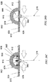
- Figs. 1A and 1B illustrate one embodiment static negative pressure device 100.
- the device 100 comprises a sealant layer 110 (also sometimes referred to herein as a sealant structure) and a collection chamber 120 (also sometimes referred to herein as a collection structure) configured to distribute pressure along a surgical area of tissue trauma, such as the length of a surgical incision.
- the device is described herein the context of the tissue being skin, although it should be appreciated that the device can be used with biological tissue other than skin.
- the negative pressure therapy device may include a contact layer 130.
- the contact layer 130 provides fluid communication between the collection chamber 120 and the area of skin trauma.
- the contact layer 130 may comprise a foam, mesh, gauze, sponge, particulate matter, a stacked mesh matrix, or any other suitable porous biocompatible material, for example.
- the contact layer 130 may be put into contact with the surface of the surgically closed area of skin trauma.
- the contact layer 130 may be configured to maintain continuity of the air/fluid spaces through the surgical site, which may reduce the occurrence of isolated fluid or air pockets in the enclosed space formed by the surgical area and the sealant layer 110.
- the contact layer may be within the borders the skin trauma surface and not contact, overlap or cover the surrounding tissue area adjacent to the skin trauma.
- the contact layer may be placed in contact with the adjacent tissue surrounding the skin trauma, in addition to the region of skin trauma itself. As shown in Fig.
- the contact layer 130, the sealant layer 110, and the collection chamber 120 may be coupled or integrated together.
- a pre-coupled or integrated design may permit the device 100 to be placed in contact with the skin trauma surface in one step.
- the contact layer is placed in contact with the skin trauma surface. Once positioned, the contact layer is then covered by the sealant layer with an integrated collection chamber to form a sealed enclosure or space.
- the sealant layer may be affixed to the area of skin surrounding the trauma area by any suitable materials or mechanisms known to one skilled in the art, including but not limited to, tape, glue, or a suitable biocompatible adhesive product.
- the collection chamber may be sized to the length of the surgically closed area of skin trauma by cutting the collection chamber or by detaching or one or more portions of the collection chamber.
- the collection chamber may have one or more pre-defined separation zones with reduced thickness to facilitate length reductions.
- a suction apparatus can then be attached or otherwise used to close the cut or separated end of the collection chamber.
- Fig. 1A shows the device 100 with a collection chamber 120 in which a suction apparatus 140 comprises with a constant force spring mechanism 142 has been integrated with the collection chamber 120. When the constant force spring mechanism 142 of the suction apparatus 140 is engaged, the slidable seal or reciprocating mechanism 144 may be drawn back to create and maintain a constant level of pressure inside the sealed enclosure.
- the device 100 has been sized to the length of a wound by cutting one end 122 of the collection chamber 120.
- Fig 1A further depicts the non-suction apparatus end 122 being occluded by an end plug 124.
- the device is further sealed in Fig. 1A using an end sealant structure 126.
- the non-suction apparatus end 122 and/or the end plug 124 may be configured to detachable or non-detachable.
- a glue may be used to irreversibly attach the end plug to the apparatus end 122.
- the length of the collection chamber may be adjusted based upon the length of the surgical incision or wound.
- the length of the surgical incision or wound may be generally linear or may be non-linear.
- the length of the collection chamber is about the length of the surgical wound, while in other examples, the collection chamber length may be about +10%, about +20%, about +30% or more, about -10%, about -20%, or about - 30% or less than the length of the surgical wound.
- surgical wounds with non-elongate configuration may also be treated.
- branching or stellate surgical wounds may be treated, using one or more devices.
- the surgical wound or incision may be characterized as the affected length of a partially dehisced surgical wound.
- the sealant layer and/or contact layer may be configured to seal or cover the dehisced segment, or the entire wound or incision. Exemplary methods for treating non-elongate wounds are described later below.
- the collection chamber per centimeter length may have a volume in the range of about 100 mm 3 to about 10,000 mm 3 or more, sometimes about 500 mm 3 to about 7,000 mm 3 , and other times about 1,000 mm 3 to about 5,000 mm 3 .
- the collection chamber 120 may be in fluid communication with the skin trauma site through the contact layer 130 of the device 100.
- the collection chamber 120 and the sealant layer 110 are integrally formed.
- the collection chamber 120 may comprise a plurality of openings 150 that may align or correspond to a plurality of openings150' in the sealant layer 110 to provide fluid communication between the skin trauma and collection chamber 120 through the contact layer 130 and the sealant layer 110.
- the series of openings 150 and 150' may permit distribution of the pressure changes applied to the area of skin trauma across the length or region of the skin trauma.
- the spacing, size or shape of the openings 150 and 150' along the collection chamber 120 and/or the sealant layer 110 may be uniform or non-uniform.
- the collection chamber 120 and the sealant layer 110 may comprise separate structures that are configured for coupling.
- the adjacent surface of the collection chamber 150 and/or the sealant layer 110 may comprise an adhesive or slip-resistant surface.
- the collection chamber openings 150 and/or openings in the sealant layer 120 may form complementary interfit to facilitate alignment.
- the collection chamber openings 150 and/or the sealant layer openings 150' may protrude into the opening in the corresponding structure.
- the collection chamber openings 150 and the sealant layer openings 150' may comprise complementary sealable snapfit.
- a collection chamber may also be configured to at least partially rotate in addition to bending.
- different sizes or configurations of openings may be provided around the circumference of the collection chamber and may be selected for use by rotation.
- the unused opening may be sealed by applying a sealant layer over the unused openings.
- the openings may be presealed and the selected seals may be utilized by removing the pre-attached seal(s) from them.
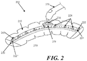
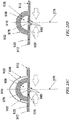
- Fig. 2 shows another embodiment of a negative pressure therapy device 200 in which the device 200 is configured to be re-evacuated or recharged.
- the device 200 comprises an integrated contact layer 230, sealant layer 210 and collection chamber 220.
- the contact layer 230 may be placed in contact with the surface of the skin trauma and a seal may be formed between the skin surrounding the skin trauma using the sealant layer 210.
- the collection chamber 220 may be integrated with the sealant layer 210 and is in fluid communication with the contact layer and the enclosed surgical site through a series of openings 250 in the collection chamber 220 and the contact layer 230, but in other examples, the collection chamber and the sealant layer may be separated components that may be attached using adhesive or mechanical mechanisms.
- the alignment of the collection chamber openings and the sealant layer openings may be facilitated by configuring either the collection chamber openings and/or the sealant layer openings with complementary interfit designs.
- the base sealant layer may lack pre-formed openings, but the collection chamber openings may comprise sharpened or penetrating structures to permit formation of sealant layer openings when the two components are coupled together.
- the collection chamber 220 may be in a pre-evacuated state wherein a level of reduced pressure is already present inside.
- the collection chamber 220 can be at atmospheric pressure when placed on the patient, and a reduced level of pressure can be created in the collection chamber using an external evacuator device 270, such as a durable medical equipment evacuator.
- the external evacuator device 270 may be positioned in an opening 276 of an evacuator fitting 278 on the collection chamber 220.
- the evacuator fitting 276 is in fluid communication with the collection chamber 220.
- the evacuator fitting 276 may be configured as a one-way flow valve that allows air molecules or other materials to be removed from the collection chamber 220 while resisting entry of air molecules or other materials into the collection chamber.
- the collection chamber 220 comprises flexion regions 228 with ribbing, but in other examples, a substantial length of the collection chamber comprises a flexible material.
- Fig. 2 also depicts a collection chamber 220 with one end 222 occluded with an end plug 224.
- the other end 222' of the collection chamber may be fitted with a one-way flow valve 260.
- the device 200 may comprise a separate one-way flow valve 260 for facilitating the emptying of the collection chamber 220 when the collection chamber 220 is filled with exudate or other matter.
- the collection chamber can then be re-evacuated using an external evacuator 270 introduced through the opening 276 of the evacuator fitting 278.
- the one-way flow valve 260 and the means for evacuating the collection chamber 220 are the same structure.
- the one-way flow valve and the means for evacuating the collection chamber are two different structures, as shown in Fig. 2.
- Fig. 2 also shows a device 200 with a moldable collection chamber 220.
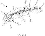
- the negative pressure therapy device 300 may comprise a multi-chamber collection system 370, comprising a first chamber 372 and a second chamber 373.
- the multiple chambers may be connected, or may be separate.
- the first and second chambers 372 and 373 may be in fluid communication with each other at an interconnecting opening 374.
- the first chamber 373 of the dual chamber collection chamber 370 has a series of openings 350 that configured to provide fluid communication with the contact layer 330 of the device 300.
- the second chamber 372 of the dual chamber collection chamber 370 can be fitted with a reciprocating mechanism for regulating pressure.
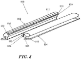
- a support 800 comprise two elongate support segments 802 and 804 which are configured to be generally joined along their longitudinal lengths at a coupling interface 806.
- a support 800 comprising separate longitudinal segments 802 and 804 may be used to separately attach each segment 802 and 804 to one edge of an incision or wound (e.g. by adhesives or suturing) and are then joined together to approximate the wound edges.
- separate joinable components may be easier to attach to the skin than a unibody support.
- the longitudinal segments 802 and 804 may be rigid, semi-rigid or flexible, and although the segments 802 and 804 are depicted as each contributing about 50% of the structure, e.g. generally symmetrically split except for possibly the coupling interface. In other examples, however, the longitudinal segments may be asymmetrically split.
- the coupling interface 806 depicted in Fig. 8 comprises a complementary set of grooves 808 and ridges 810 located along the longitudinal inner surface 812 of each segment 802 and 804, but any of a variety of coupling interfaces 806 may be used, including other snapfits.
- locking interfaces, mechanisms or structures may include but are not limited to resealable adhesive layers, slide locks, hinge clamps, clips, locking pins with lockable lumens, zippers, elastic binding bands, and the like.
- structures that may be used to contract the sealant layer into a unibody support may also be used to contract the sealant layer into a multi-segment support and/or to couple the segments of a multi-segment support together.
- Fig. 9A depicts one example of a negative pressure therapy system 900 comprising an elastic support 902 and an optional suction system 904.
- An optional contact layer 906 may be provided under the elastic support 902.
- the elastic support 902 is configured with one or more longitudinal conduits 908 or channels.
- the conduit or channel may be fully enclosed or may be at least partially open.
- the conduit 908 in Fig. 9 has a closed configuration with a plurality of apertures 910 to permit air or fluid communication with the underlying wound or incision.
- the lateral flaps 912 of the elastic support 904 may comprise an adhesive, which may be used to at least seal a portion of the conduit 908 and the external space, if any, between the incision or wound and the apertures 910.
- the lateral flaps 912 may extend to one or both ends of the support, but in the example, depicted in Fig. 9A , end seals 914 and/or 916 may be used to facilitate sealing about the ends 918 and 920 of the support 902.
- at least one of the end seals 916 may be provided with a connector 922 for attachment of the suction system 904, but in other embodiments, the connector may be located on the elastic support 902.
- a large sealant layer may be used to cover a larger portion if not all of the support, and with or without a protective layer.
- some embodiments of the elastic support may comprise segmented non-sealing lateral flaps which are configured to elastically bring wound edges together. The segmentation may facilitate the application of the elastic support in a sectional manner, but may or may not provide sealing ability, such that a sealant layer applied over the elastic support may be used to provide a sealed space about the support.
- the flaps 912 of the elastic support 902 may be elastically stretched or pulled away from each other and applied in its stretched state to the incision or wound such that each flap 912 is adhered to the skin surface 922 to a respective edge of the incision or wound.
- the support 902 may be sufficient stiff or rigid such that a substantial longitudinal length of the flaps 912 can be stretched, but in other configurations, a smaller portion of the flaps 912 may be pulled away, which may facilitate the application of the support to non-linear incisions or wound by permitting adherence or attachment of the support section-by-section.
- Fig. 9E depicts how two elastic supports 902 with flaps 912 may be positioned serially or in an end-to-end fashion to treat incisions or wounds having a longer length by covering the junction 958 with an accessory seal 960. As noted previously, although the ends of the supports 902 and their flaps 912 are depicted as touching at the junction region 958, in other examples, partial or full gaps may be provided between supports and/or their flaps.
- the elastic support may comprise any of a variety of configurations.
- the elastic support 902 may comprise an elastomeric member 926 which may augment the elastomeric properties, if any, of the flaps 912 and/or wall 928 of the conduit 908.
- the apertures 910 of the elastic support 902 may be provided directly in the elastomeric member 926, and in some configurations the apertures 910 may also deform in shape when force is applied to the flaps 912.
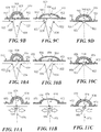
- Fig. 10A to 10C depicts another embodiment of an elastic support 950 with flaps 952, wherein the apertures 954 are provided in a non-elastic structure 956.
- the non-elastic structure 956 may have any of a variety of configurations, including rings or frames, and may form either a partial or a complete perimeter of the aperture 954.
- the non-elastic structures 956 may be separate for each aperture 954 or they may be interconnected.
- Fig. 11A to 11C depicts still another embodiment of an elastic support 970 with flaps 972 comprises an elastic material such that a specific elastomeric member is not used.
- the elastic support 970 comprise an open channel 974 that lacks discrete apertures and instead is generally open along the length of the channel 974 to the edges 922 and space 924 of the underlying incision or wound.
- the elastic support 970 may be applied to an incision 976 closed with sutures 978 or other type of incision closure such as staples.
- the sutures 978 may any type of suture and may be used with any of a variety of suture techniques, including running sutures and interrupted sutures. In some variations, although the sutures 978 may generally maintain the approximation of the wound edges 980, separation forces acting at the sutures 978 may generate focal regions of tissue tension.
- Application of the elastic support 970 to the incision may be used to apply additional contiguous force along a substantial length of the incision 976, which may or may not reduce the focal tissue tension and possibly improve incision healing.
- the devices described herein may also be used to treat non-elongate incisions or wounds.
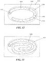
- Figs. 12 to 15 depict various examples of using an elongate negative pressure therapy system to treat non-elongate wounds.
- an elongate negative pressure therapy device 1000 and a sealant layer 1002 are positioned around the perimeter of wound 1004.
- the device 1000 may comprise apertures 1006, 1008 and 1010 of varying size.
- smaller apertures 1004 may be used at distances closer to the suction source or interface 1012, while larger apertures 1008 may be used at relatively farther distances.
- the size of the apertures may be uniform, but either the number and/or the spacing of the apertures may vary along the longitudinal length of the device.
- Fig. 13 depicts another example of a negative pressure therapy device 1020 arranged in a spiral orientation with respect to a wound 1022.
- the spiral orientation may augment the pressure or suction about the center of the wound 1022, compared to the device arranged depicted in Fig. 12 .
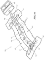
- Fig. 14 is still another example of a device 1030 comprising alternating rigid sections 1032 and flexion sections 1034 arranged in a back-and-forth or zig-zag orientation along a non-elongate wound 1036.
- the rigid sections 1032 may also rotate with respect to the flexion section 1034 or other articulation of the device.
- the device need not be fully located within the borders of the wound 1036, and although all of the device apertures 1038 are located within the wound borders, in other examples one or more apertures may be located outside the border of the wound.
- Such variations can include situations where the musculature and surrounding wound tissue has been paralyzed, e.g., through the use of botulinim toxin or the like.
- the devices shield the area of skin trauma from both endogenous and exogenous stress.
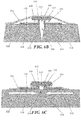
- the device may contract to a state wherein the distance 1705 has been reduced to substantially about zero and the limiting elements 1703 and 1704 are in direct physical contact with one another or otherwise restricting further contraction of the sealant layer 1702.
- the device does not necessarily contract to a state wherein the distance 1705 has been reduced to zero.
- the device 1700 may or may not be configured to have residual tension remaining in sealant layer 1702.
- further contraction may occur, but the interaction of the proximal limiting element 1703 and the distal limiting element 1704 may be configured to resist or prevent further contraction of sealant layer 1702, thereby limiting the compressive stress that the device applies on the closed incision.
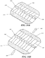
- Fig. 18A depicts another example of a device 1800, comprising a collection chamber 1801 and sealant layer 1802, and further comprising a carrier structure 1803 that can also serve as a delivery tool.
- the sealant layer 1802 may be maintained in a stretched state with residual tension by presence of the carrier structure 1803.
- the carrier structure 1803 may comprise a series of transverse elements or ribs 1804 which provide the carrier structure 1803 with transverse rigidity, which may allow the carrier structure 1803 to maintain the sealant layer 1802 in a stretched state.
- the transverse ribs 1804 are separated by spaces between successive transverse ribs 1804.
- the spaces permit the transverse ribs 1804 to move relative to one another, which allows the carrier structure 1803 to be flexible longitudinally and to conform to a curvilinear incision, as depicted in Fig. 18A , which shows the device in a state of longitudinal flexure.
- the carrier structure 1803 may be removed, which allows residual tension in sealant layer 1802 to act upon and apply compressive stress to the closed incision.
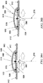
- the device may also be configured as depicted in Fig. 18B to be positioned in a relaxed state in which the sealant layer 1802 remains unstretched or minimally stretched while connected to the carrier structure 1803. With deformation of the carrier structure 1803 as shown in Fig. 18C , the sealant layer 1802 then attains a substantially stretched state prior to application of the closed incision site.
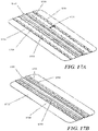
- Fig. 19 is a perspective inferior view of an embodiment wherein the device 1900 is configured to serve as a vehicle for delivery of agents.
- the device comprises a sealing surface 1901 which in turn comprises adhesive tabs 1902 that extend outwardly from the sealing surface 1901 with spaces between the tabs 1902 for increased flexibility.
- the device 1900 also comprises a collection chamber 1903 as well as delivery chambers 1904.
- the collection chamber 1903 comprises plurality of collection passageways 1905 and delivery chambers 1904, which comprise a plurality of delivery passageways 1906.
- the collection chamber 1903 may be connected to a reduced pressure source to apply reduced pressure to the closed incision.
- the delivery chambers 1904 are connected to a source of agents to be delivered and are not in direct fluid communication with collection chamber 1905.
- agents to be delivered may be directed into delivery chambers 1904 and through delivery passageways 1906 to the closed incision area.
- Reduced pressure may be applied through the collection chamber 1903 and communicated to the closed incision area through collection passageways 1905.
- agents to be delivered are introduced into the closed incision without being immediately removed by the reduced pressure source. This may be due to the distance between delivery passageways and collection passageways.
- the pre-stretching element enables pre-stretching of the device and maintains the device in a pre-stretched state prior to application of the device to the skin.
- the pre-stretching element may be removed from the device after application to the skin. Upon removal of the pre-stretching element, residual tension in the sealant layer is released. The residual tension in the sealant layer is transferred to the skin, and may cause the sealant layer to tend to contract along the direction of the residual tension. This may impart transverse compressive stresses on the closed incision, which may oppose the tendency of the opposing edges of the closed incision to pull apart.
- a central pre-stretching element 990 may be used to increase the space between the flaps 912 of the elastic support 902 of a reduced pressure therapy system (such as for the embodiment of the elastic support 902 shown in Figure 9 ).
- the pre-stretching element 990 can also be used as a delivery tool.
- the presence of the pre-stretching element 990 permits the elastic support 902 to be applied in a stretched state to an incision or wound such that each flap 912 is adhered to the skin surface 920 of a respective edge of the incision or wound.
- the elastic support is shown in a pre-stretched state where the pre-stretching element 990 is in an expanded state and maintains the elastomeric members 926 in a stretched configuration.
- the conduit walls 928 are also depicted in a stretched configuration in Figure 20A .
- Figures 20E-20F show an enlarged view of an exemplary embodiment of the pre-stretching element 990 in an expanded state.
- the pre-stretching element 990 in an unexpanded state is shown in Fig. 20G .
- the pre-stretching element includes a set of expansion rails 991 connected to a central bar 992 via hinging struts 992.
- the expansion rails 991 extend along a long axis of the pre-stretching element 992 with the hinging struts positioned transversely relative to the expansion rails 991 and in a hinged relationship with the expansion rails 991.
- the central bar 992 is coupled to a set of finger holes 993, 994.
- a user can achieve relative motion of the expansion rails and the central bar to transition the pre-stretching element 990 between the unexpanded and expanded states.
- Relative motion of the rails 991 to the central bar 992 occurs with motion of the finger holes 993 and 994 relative to one another.
- a latch tab 995 may be used to secure or lock the finger holes 993, 994 in a proximal position that causes the hinging struts 992 to separate the distance between the rails 991 as seen in Figs. 20E and 20F .
- the latch tab 995 may also be released to allow the pre-stretching element to return to the unexpanded state shown in Fig. 20G .
- the flaps 912 of the elastic support 902 of Figure 9 may be elastically stretched or pulled away from each other and applied in its stretched state to the incision or wound such that each flap 912 is adhered to the skin surface 920 to a respective edge of the incision or wound. Stretching of the flaps 912 and their elastomeric members 926 may be limited in extent by an inelastic member 996, as seen in Fig. 2 IB.
- the inelastic member 996 has a first end attached to one of the flaps 912 and a second end attached to another of the flaps 912 on an opposite side of the wound.
- the inelastic member 996 is positioned over the elastic support 902. That is, the inelastic member 996 is at least partially positioned on top of, but not necessarily in contact with, the elastic support 902 with respect to the orientation shown in Figures 21A-21D .
- the stretching or deformation force may be relieved, and the elasticity or bias in the support 902 and elastomeric members 926 may push the closed incision edges 980 toward each other.
- the elastic support 902 may be applied to an incision 976 closed with sutures 978 or other type of incision closure such as staples.
- the sutures 978 may any type of suture and may be used with any of a variety of suture techniques, including running sutures and interrupted sutures. In some variations, although the sutures 978 may generally maintain the approximation of the closed incision edges 980, separation forces acting along the wound closure may generate focal regions of tissue tension.
- Application of the elastic support 902 to the incision may be used to apply additional contiguous force along a substantial length of the incision 976, which can reduce the focal tissue tension and possibly improve incision healing.
- the inelastic member Once applied to the skin surface 920 as shown in Fig 21C , the inelastic member may then be removed as shown in Fig 21D if desired.
Claims (16)
- Système de traitement de plaies (900, 1600, 1800) comprenant :(a) une structure d'étanchéité flexible (902) comprenant une surface supérieure, une surface inférieure et un adhésif, la structure d'étanchéité flexible (902) étant conçue pour réaliser une étanchéité autour d'une zone de la lésion des tissus ;(b) un passage (908, 910, 974) pour exposer la zone de la lésion des tissus à une pression réduite ; etcaractérisé en ce que(c) au moins une portion du système (900) est configurée pour exercer une force sur les tissus afin de relâcher la tension sur la zone de la lésion des tissus, et le système (900) comprend en outre au moins un élément de contrôle de force orienté le long d'un axe de la structure d'étanchéité flexible (902), l'axe étant essentiellement orienté en direction transversale par rapport à une incision associée à la zone de la lésion des tissus, et l'élément de contrôle de force comprenant au moins un élément de limitation d'allongement, et l'élément de contrôle de force étant configuré pour offrir un contrôle sur un degré de force que le système (900) applique aux tissus en limitant le degré d'allongement qui peut être réalisé par au moins une portion de la structure d'étanchéité flexible (902).
- Système (900) selon la revendication 1, dans lequel ledit au moins un élément de limitation d'allongement est relié à la structure d'étanchéité flexible (902).
- Système (900) selon la revendication 2, dans lequel l'élément de limitation d'allongement peut passer d'un état initial qui permet un premier degré d'allongement de la structure d'étanchéité flexible (902) et un second état qui permet un second degré d'allongement de la structure d'étanchéité flexible (902).
- Système (900) selon la revendication 3, dans lequel l'élément de limitation d'allongement peut passer à des états intermédiaires entre le premier et le second état, les états intermédiaires permettant des degrés intermédiaires d'allongement entre le premier et le second degré.
- Système (1600) selon la revendication 2, dans lequel ledit au moins un élément de limitation d'allongement comprend au moins un élément oblong (1605) qui peut être allongé jusqu'à une longueur maximum le long de l'axe longitudinal de l'élément oblong (1605), l'élément oblong (1605) résistant à l'allongement de la structure d'étanchéité flexible (1602) au-delà d'une limite de distance.
- Système (1600) selon la revendication 1, dans lequel la structure d'étanchéité flexible (1602) comprend plusieurs pattes (1603) qui peuvent être saisies par un utilisateur pour appliquer une force à la structure d'étanchéité flexible (1602) afin d'allonger la structure d'étanchéité flexible (1602).
- Système (1800) selon la revendication 1, comprenant en outre une structure de support (1803) reliée de manière amovible à la structure d'étanchéité flexible (1802), la structure de support (1803) maintenant la structure d'étanchéité flexible (1802) dans un état allongé lorsque la structure de support (1803) est reliée à la structure d'étanchéité flexible (1802).
- Système (1800) selon la revendication 7, dans lequel la structure de support (1803) comprend une série de nervures (1804) qui rendent la structure d'étanchéité flexible (1802) essentiellement rigide lorsque la structure de support (1803) est reliée à la structure d'étanchéité flexible (1802).
- Système (1800) selon la revendication 7, dans lequel la structure de support (1803) peut être retirée de la structure d'étanchéité flexible (1802) et dans lequel le retrait de la structure de support (1803) permet à la structure d'étanchéité flexible (1802) de se contracter à partir de l'état sous contrainte.
- Système (1800) selon la revendication 1, comprenant en outre un outil d'administration relié à la structure d'étanchéité flexible (1802), l'outil d'administration comprenant plusieurs éléments transversaux (1804) conçus pour être orientés transversalement par rapport à un axe de la lésion des tissus quand le système (1800) est placé sur les tissus.
- Système (1800) selon la revendication 10, dans lequel les éléments transversaux (1804) sont conçus pour déplacer une première zone de la structure d'étanchéité flexible (1802) par rapport à une seconde zone de la structure d'étanchéité flexible (1802).
- Système (900) selon la revendication 1, dans lequel la portion du système (900) exerce une force sur le tissu lorsque le système (900) est placé initialement sur la peau.
- Système (900) selon la revendication 1, dans lequel ledit au moins un élément de limitation d'allongement comprend un élément inélastique (996) dont une première extrémité est fixée à une première zone de la structure d'étanchéité flexible (902) et une seconde extrémité est fixée à une seconde extrémité de la structure d'étanchéité flexible (902), dans lequel la première extrémité et la seconde extrémité sont configurées pour venir se disposer sur des côtés opposés de la lésion des tissus.
- Système selon la revendication 1, dans lequel la structure d'étanchéité flexible (902) est élastique.
- Système (900) selon la revendication 1, dans lequel le système (900) est configuré pour limiter un degré de force externe appliquée sur la peau, la force externe étant indépendante de la force exercée par la peau elle-même.
- Système (900) selon la revendication 1, comprenant en outre une structure collectrice reliée à la structure d'étanchéité flexible (902), la structure d'étanchéité flexible (902) et la structure collectrice formant conjointement un conduit (908) qui communique avec la zone de la lésion des tissus.
Priority Applications (1)
| Application Number | Priority Date | Filing Date | Title |
|---|---|---|---|
| EP17171386.0A EP3235525B1 (fr) | 2009-04-10 | 2010-04-09 | Dispositifs pour l'application d'un traitement par pression négative sur des plaies d'incision fermées |
Applications Claiming Priority (2)
| Application Number | Priority Date | Filing Date | Title |
|---|---|---|---|
| US16850709P | 2009-04-10 | 2009-04-10 | |
| EP10715015.3A EP2416816B1 (fr) | 2009-04-10 | 2010-04-09 | Procédés et dispositifs pour l'application d'un traitement par pression négative sur des plaies d'incision fermées |
Related Parent Applications (1)
| Application Number | Title | Priority Date | Filing Date |
|---|---|---|---|
| EP10715015.3A Division EP2416816B1 (fr) | 2009-04-10 | 2010-04-09 | Procédés et dispositifs pour l'application d'un traitement par pression négative sur des plaies d'incision fermées |
Related Child Applications (1)
| Application Number | Title | Priority Date | Filing Date |
|---|---|---|---|
| EP17171386.0A Division EP3235525B1 (fr) | 2009-04-10 | 2010-04-09 | Dispositifs pour l'application d'un traitement par pression négative sur des plaies d'incision fermées |
Publications (2)
| Publication Number | Publication Date |
|---|---|
| EP2905037A1 EP2905037A1 (fr) | 2015-08-12 |
| EP2905037B1 true EP2905037B1 (fr) | 2017-05-17 |
Family
ID=42501445
Family Applications (3)
| Application Number | Title | Priority Date | Filing Date |
|---|---|---|---|
| EP14188893.3A Active EP2905037B1 (fr) | 2009-04-10 | 2010-04-09 | Dispositifs pour l'application d'un traitement par pression négative sur des plaies d'incision fermées |
| EP10715015.3A Active EP2416816B1 (fr) | 2009-04-10 | 2010-04-09 | Procédés et dispositifs pour l'application d'un traitement par pression négative sur des plaies d'incision fermées |
| EP17171386.0A Active EP3235525B1 (fr) | 2009-04-10 | 2010-04-09 | Dispositifs pour l'application d'un traitement par pression négative sur des plaies d'incision fermées |
Family Applications After (2)
| Application Number | Title | Priority Date | Filing Date |
|---|---|---|---|
| EP10715015.3A Active EP2416816B1 (fr) | 2009-04-10 | 2010-04-09 | Procédés et dispositifs pour l'application d'un traitement par pression négative sur des plaies d'incision fermées |
| EP17171386.0A Active EP3235525B1 (fr) | 2009-04-10 | 2010-04-09 | Dispositifs pour l'application d'un traitement par pression négative sur des plaies d'incision fermées |
Country Status (7)
| Country | Link |
|---|---|
| US (3) | US8409159B2 (fr) |
| EP (3) | EP2905037B1 (fr) |
| JP (3) | JP5650199B2 (fr) |
| AU (1) | AU2010233221B2 (fr) |
| CA (1) | CA2757841C (fr) |
| DK (1) | DK2416816T3 (fr) |
| WO (1) | WO2010118316A1 (fr) |
Families Citing this family (71)
| Publication number | Priority date | Publication date | Assignee | Title |
|---|---|---|---|---|
| US9820888B2 (en) | 2006-09-26 | 2017-11-21 | Smith & Nephew, Inc. | Wound dressing |
| AU2008310622B2 (en) | 2007-10-11 | 2014-01-09 | Solventum Intellectual Properties Company | Closed incision negative pressure wound therapy device and methods of use |
| EP3360519B1 (fr) | 2007-11-21 | 2020-11-18 | Smith & Nephew plc | Pansement de plaie |
| GB0804654D0 (en) | 2008-03-13 | 2008-04-16 | Smith & Nephew | Vacuum closure device |
| US8444614B2 (en) | 2009-04-10 | 2013-05-21 | Spiracur, Inc. | Methods and devices for applying closed incision negative pressure wound therapy |
| US10792404B2 (en) * | 2009-04-10 | 2020-10-06 | Kci Licensing, Inc. | Methods and devices for applying closed incision negative pressure wound therapy |
| EP2905037B1 (fr) | 2009-04-10 | 2017-05-17 | KCI Licensing, Inc. | Dispositifs pour l'application d'un traitement par pression négative sur des plaies d'incision fermées |
| WO2011079132A1 (fr) * | 2009-12-23 | 2011-06-30 | C. R. Bard, Inc. | Système de collecte de fluide biologique |
| US9061095B2 (en) | 2010-04-27 | 2015-06-23 | Smith & Nephew Plc | Wound dressing and method of use |
| GB201015656D0 (en) | 2010-09-20 | 2010-10-27 | Smith & Nephew | Pressure control apparatus |
| CA140189S (en) | 2010-10-15 | 2011-11-07 | Smith & Nephew | Medical dressing |
| CA140188S (en) | 2010-10-15 | 2011-11-07 | Smith & Nephew | Medical dressing |
| US8986269B2 (en) * | 2010-11-11 | 2015-03-24 | Ulcerx Medical Inc. | Wound leakage vacuum collection device |
| JP6241877B2 (ja) | 2010-12-01 | 2017-12-06 | ダニエル・エデュアード・クライナー | 管腔内減圧療法に使用される器具 |
| US9421132B2 (en) | 2011-02-04 | 2016-08-23 | University Of Massachusetts | Negative pressure wound closure device |
| EP2670312B1 (fr) | 2011-02-04 | 2020-11-18 | University of Massachusetts | Dispositif de fermeture de plaie par pression négative |
| CN103533900B (zh) * | 2011-03-31 | 2016-12-28 | 佛尔蒙特·伊夫斯 | 调整力的组织间桥 |
| WO2012170744A2 (fr) * | 2011-06-07 | 2012-12-13 | Spiracur, Inc. | Solutions pour le pontage et la réduction de concentration de pression à des sites de plaie |
| CN103702710B (zh) * | 2011-07-19 | 2016-06-29 | 心脏防护医疗技术公司 | 在负压伤口治疗中的稳定器、包括稳定器的隔离片及伤口敷料、用于控制伤口敷料或隔离片的位置的方法、以及用于促进从伤口敷料或隔离片引流的方法 |
| WO2013059600A1 (fr) | 2011-10-20 | 2013-04-25 | Eaves Felmont | Revêtement amovible et emballage interactif |
| US9084845B2 (en) | 2011-11-02 | 2015-07-21 | Smith & Nephew Plc | Reduced pressure therapy apparatuses and methods of using same |
| CN104010665B (zh) | 2011-11-02 | 2016-10-19 | 史密夫及内修公开有限公司 | 减压治疗设备及其使用方法 |
| CN104244899B (zh) * | 2012-01-11 | 2018-04-13 | 赛诺龙医疗公司 | 大面积美体塑形的帖敷器 |
| AU2013234034B2 (en) | 2012-03-12 | 2017-03-30 | Smith & Nephew Plc | Reduced pressure apparatus and methods |
| EP2852419B1 (fr) | 2012-05-22 | 2019-11-20 | Smith & Nephew plc | Dispositif de fermeture de blessure |
| CN104661601B (zh) | 2012-05-22 | 2018-06-22 | 史密夫及内修公开有限公司 | 用于伤口治疗的设备和方法 |
| JP6285421B2 (ja) | 2012-05-24 | 2018-02-28 | スミス アンド ネフュー インコーポレイテッド | 陰圧により創傷を治療および閉鎖するデバイスおよび方法 |
| WO2013181686A1 (fr) * | 2012-06-03 | 2013-12-12 | Daniel Eduard Kleiner | Dispositif endoluminal de thérapie par le vide |
| MX369689B (es) | 2012-07-16 | 2019-11-19 | Smith & Nephew Inc | Dispositivo de cierre de herida de presión negativa. |
| US9968488B2 (en) | 2012-11-12 | 2018-05-15 | Kci Usa, Inc. | Externally-applied patient interface system and method |
| DE102012223399A1 (de) | 2012-12-17 | 2014-06-18 | Paul Hartmann Ag | Zuschneidbarer Wundverband |
| US20140191263A1 (en) | 2013-01-07 | 2014-07-10 | Sabic Innovative Plastics Ip B.V. | Compositions for an led reflector and articles thereof |
| CA2902776C (fr) | 2013-03-13 | 2023-03-07 | Smith & Nephew Inc. | Appareil de traitement des plaies et son utilisation |
| RU2015142877A (ru) | 2013-03-14 | 2017-04-18 | СМИТ ЭНД НЕФЬЮ ПиЭлСи | Сжимаемые наполнители раны и системы и способы их применения в лечении ран с применением отрицательного давления |
| EP2968871B8 (fr) * | 2013-03-15 | 2017-08-23 | KCI Licensing, Inc. | Pansements topiques à pression négative pour incisions chirurgicales, adjuvants chirurgicaux, hybrides et composites |
| US10660992B2 (en) | 2013-10-21 | 2020-05-26 | Smith & Nephew, Inc. | Negative pressure wound closure device |
| RU2016133735A (ru) | 2014-01-21 | 2018-02-28 | СМИТ ЭНД НЕФЬЮ ПиЭлСи | Сжимаемая повязка для лечения раны отрицательным давлением |
| CA2936873A1 (fr) * | 2014-02-11 | 2015-08-20 | Spiracur Inc. | Procedes et dispositifs pour l'application d'une therapie par pression negative sur une incision fermee |
| CN104117131B (zh) * | 2014-07-22 | 2016-05-11 | 翁跃勤 | 一种负压切口愈合器 |
| DK3288508T3 (da) | 2015-04-27 | 2020-03-09 | Smith & Nephew | Anordninger med reduceret tryk |
| EP4209201A1 (fr) | 2015-04-29 | 2023-07-12 | Smith & Nephew, Inc. | Dispositif de fermeture de plaie par pression négative |
| CN105147344B (zh) * | 2015-10-19 | 2018-12-21 | 张新平 | 皮肤伤口辅助愈合装置 |
| CN105147345B (zh) * | 2015-10-19 | 2019-12-13 | 张新平 | 皮肤伤口负压减张缝合装置 |
| US10575991B2 (en) * | 2015-12-15 | 2020-03-03 | University Of Massachusetts | Negative pressure wound closure devices and methods |
| US10814049B2 (en) | 2015-12-15 | 2020-10-27 | University Of Massachusetts | Negative pressure wound closure devices and methods |
| CN114053031A (zh) | 2016-03-07 | 2022-02-18 | 史密夫及内修公开有限公司 | 利用整合到伤口敷料中的负压源的伤口治疗设备和方法 |
| CN114469523A (zh) | 2016-04-26 | 2022-05-13 | 史密夫及内修公开有限公司 | 与具有流体侵入抑制部件的一体化负压源一起使用的伤口敷料和方法 |
| EP3452129B1 (fr) | 2016-05-03 | 2022-03-23 | Smith & Nephew plc | Activation et commande d'un dispositif de traitement des plaies par pression négative |
| CA3022587A1 (fr) | 2016-05-03 | 2017-11-09 | Smith & Nephew Plc | Systemes et procedes pour commander des sources de pression negative dans des systemes de traitement par pression negative |
| AU2017259906B2 (en) | 2016-05-03 | 2022-06-02 | Smith & Nephew Plc | Optimizing power transfer to negative pressure sources in negative pressure therapy systems |
| AU2017315129B2 (en) | 2016-08-25 | 2022-10-27 | Smith & Nephew Plc | Absorbent negative pressure wound therapy dressing |
| EP3519001A1 (fr) | 2016-09-30 | 2019-08-07 | Smith & Nephew PLC | Appareils et procédés de traitement de plaies par pression négative avec électronique intégrée |
| WO2018075879A1 (fr) | 2016-10-21 | 2018-04-26 | Emrge, Llc. | Ponts tissulaires à modulation de force, outils associés, kits et procédés |
| JP7361606B2 (ja) | 2017-03-08 | 2023-10-16 | スミス アンド ネフュー ピーエルシー | 障害状態の存在下での陰圧創傷療法装置の制御 |
| SG11201910129SA (en) | 2017-05-09 | 2019-11-28 | Smith & Nephew | Redundant controls for negative pressure wound therapy systems |
| CN111065424A (zh) | 2017-09-13 | 2020-04-24 | 史密夫及内修公开有限公司 | 具有集成电子器件的负压伤口治疗设备及方法 |
| GB201718070D0 (en) | 2017-11-01 | 2017-12-13 | Smith & Nephew | Negative pressure wound treatment apparatuses and methods with integrated electronics |
| US10888643B2 (en) * | 2017-10-07 | 2021-01-12 | Thomas Zink | Negative pressure interbody device, system, and method |
| USD862695S1 (en) | 2017-10-20 | 2019-10-08 | Emrge, Llc | Medical tool for use in applying medical article |
| USD876641S1 (en) | 2017-10-20 | 2020-02-25 | Emrge, Llc. | Medical article for treating a wound and/or scar tissue |
| EP3703632B1 (fr) | 2017-11-01 | 2024-04-03 | Smith & Nephew plc | Appareils et procédés de traitement de plaies par pression négative avec électronique intégrée |
| GB201718072D0 (en) | 2017-11-01 | 2017-12-13 | Smith & Nephew | Negative pressure wound treatment apparatuses and methods with integrated electronics |
| GB201718054D0 (en) | 2017-11-01 | 2017-12-13 | Smith & Nephew | Sterilization of integrated negative pressure wound treatment apparatuses and sterilization methods |
| US10624794B2 (en) | 2018-02-12 | 2020-04-21 | Healyx Labs, Inc. | Negative pressure wound therapy systems, devices, and methods |
| USD898925S1 (en) | 2018-09-13 | 2020-10-13 | Smith & Nephew Plc | Medical dressing |
| WO2020124038A1 (fr) | 2018-12-13 | 2020-06-18 | University Of Massachusetts | Dispositifs et méthodes de fermeture de plaie par pression négative |
| US11305052B2 (en) | 2019-04-07 | 2022-04-19 | Steven Simpson | Suction-based medical dressing and method of dermal irrigation |
| CN110226946B (zh) * | 2019-06-12 | 2022-05-17 | 杭州市第三人民医院 | 泌尿外科手术标本收集器 |
| CN117562739A (zh) * | 2019-06-20 | 2024-02-20 | 杨国煌 | 承载流体的敷贴 |
| EP4041095A4 (fr) | 2019-10-11 | 2023-11-08 | Brijjit Medical, Inc. | Dispositif médical d'application de force sur du tissu biologique, ou similaire |
| USD980434S1 (en) | 2021-01-14 | 2023-03-07 | Emrge, Llc | Medical article for treating a wound and/or scar tissue |
Family Cites Families (174)
| Publication number | Priority date | Publication date | Assignee | Title |
|---|---|---|---|---|
| US114750A (en) * | 1871-05-16 | Improvement in sticking or adhesive plasters | ||
| US676334A (en) * | 1900-02-08 | 1901-06-11 | George J Miller | Method of making electrodes for storage batteries, &c. |
| US2012755A (en) * | 1934-07-12 | 1935-08-27 | Muth Otto De | Surgical dressing |
| US2198666A (en) | 1936-09-30 | 1940-04-30 | Lakeland Foundation | Syringe |
| US2472116A (en) | 1945-10-18 | 1949-06-07 | Emma C Maynes | Syringe holder |
| US2531757A (en) * | 1947-02-05 | 1950-11-28 | Margaret S Whinery | Bandage |
| US2660342A (en) | 1949-04-01 | 1953-11-24 | Ruf Herman | Burette with variable capacity |
| US2863452A (en) | 1954-06-22 | 1958-12-09 | Ogle Edna | Syringe with adjustable aspirating means |
| US3334628A (en) | 1964-07-17 | 1967-08-08 | Orthopedic Equipment Company I | Vacuum indicating connection for surgical wound-closing apparatus |
| AT295031B (de) * | 1967-01-10 | 1971-12-27 | Radivoje Dr Vukojevic | Klebeband als Ersatz für eine Hautnaht |
| US3628325A (en) | 1968-07-02 | 1971-12-21 | Seiko Instr & Electronics | Self-winding watch |
| US3487836A (en) * | 1968-07-16 | 1970-01-06 | Benjamin W Niebel | Surgical strip stitch |
| CA873458A (en) | 1968-09-03 | 1971-06-15 | F. Ritsky Anthony | Self-aspirating syringe |
| US3680560A (en) | 1968-11-26 | 1972-08-01 | Voys Inc Le | Vacuum drainage collecting apparatus with disposable liner |
| US3779243A (en) | 1971-10-15 | 1973-12-18 | J Tussey | Contamination free surgical evacuator |
| BE792506A (fr) | 1971-12-09 | 1973-03-30 | Sherwood Medical Ind Inc | Dispositifs de drainage médical |
| US3841331A (en) | 1972-11-17 | 1974-10-15 | J Wilder | Suction-pump assembly for drawing body fluids |
| US3833030A (en) | 1973-03-05 | 1974-09-03 | E Flippo | Device for withdrawing or adding fluids to hypodermic syringes |
| US3809087A (en) | 1973-05-17 | 1974-05-07 | R Lewis | Closed wound suction apparatus having biased plate members |
| US3982546A (en) | 1975-02-28 | 1976-09-28 | Friend John H | Device for draining a body cavity |
| US4041934A (en) | 1976-02-02 | 1977-08-16 | Abbott Laboratories | Arterial blood sampling unit |
| US4080970A (en) | 1976-11-17 | 1978-03-28 | Miller Thomas J | Post-operative combination dressing and internal drain tube with external shield and tube connector |
| US4278089A (en) | 1978-11-09 | 1981-07-14 | Howmedica, Inc. | Wound drainage device |
| GB2047543B (en) | 1978-12-06 | 1983-04-20 | Svedman Paul | Device for treating tissues for example skin |
| US4266545A (en) | 1979-04-06 | 1981-05-12 | Moss James P | Portable suction device for collecting fluids from a closed wound |
| USD265423S (en) * | 1980-03-14 | 1982-07-13 | Consolidated Medical Equipment Inc. | I.V. Bandage |
| US4404924A (en) | 1980-09-05 | 1983-09-20 | Uresil Company | Body fluid suction device indicators |
| US4333458A (en) | 1981-02-09 | 1982-06-08 | Sterling Drug Inc. | Self-aspirating syringe with positively engaged locking collet |
| US4333456A (en) | 1981-02-09 | 1982-06-08 | Sterling Drug Inc. | Self-aspirating hypodermic syringe and self-aspirating assembly therefor |
| KR840004357A (ko) * | 1982-04-12 | 1984-10-15 | 콘라드 마리 쉬한 조세프 | 환부 봉합장치 |
| US4535772A (en) * | 1983-03-10 | 1985-08-20 | Kells Medical, Incorporated | Skin closure device |
| US4578060A (en) | 1983-07-20 | 1986-03-25 | Howmedica, Inc. | Wound drainage device |
| US4664128A (en) | 1983-12-16 | 1987-05-12 | Peter F. Lee, Inc | Single-hand controlled aspiration device |
| US4549554A (en) | 1984-01-03 | 1985-10-29 | Markham Charles W | Aspiration biopsy device |
| US5266476A (en) | 1985-06-18 | 1993-11-30 | Yeda Research & Development Co., Ltd. | Fibrous matrix for in vitro cell cultivation |
| JPS62197334U (fr) * | 1986-06-04 | 1987-12-15 | ||
| GB2195255B (en) | 1986-09-30 | 1991-05-01 | Vacutec Uk Limited | Apparatus for vacuum treatment of an epidermal surface |
| US4743232A (en) | 1986-10-06 | 1988-05-10 | The Clinipad Corporation | Package assembly for plastic film bandage |
| DK154747C (da) | 1986-10-17 | 1989-05-08 | Coloplast As | Bandage med en hudvenlig, vandabsorberende klaebeskive der paa den ene flade er fast forbundet med en ikke-klaebende daekfilm og paa den anden med et aftageligt beskyttelsesdaekke |
| US4929577A (en) * | 1987-03-11 | 1990-05-29 | Medi-Tech International Corporation | Transparent wound dressings in sheet form |
| US4758232A (en) | 1987-09-08 | 1988-07-19 | Chak Choi K | Suction syringe with an automatic locking means |
| US5116610A (en) | 1987-12-29 | 1992-05-26 | The Procter & Gamble Company | Compositions for treating hypercholesterolemia |
| US4882337A (en) | 1988-08-12 | 1989-11-21 | Pfizer Inc. | Tetrahydroisoquinoline antiarrhythmic agents |
| US5261893A (en) | 1989-04-03 | 1993-11-16 | Zamierowski David S | Fastening system and method |
| US5100396A (en) | 1989-04-03 | 1992-03-31 | Zamierowski David S | Fluidic connection system and method |
| US4969880A (en) | 1989-04-03 | 1990-11-13 | Zamierowski David S | Wound dressing and treatment method |
| US5527293A (en) | 1989-04-03 | 1996-06-18 | Kinetic Concepts, Inc. | Fastening system and method |
| IL93045A (en) | 1990-01-12 | 1995-01-24 | Rosenberg Lior | A particularly usable vacuum device for removing wound fluid |
| DE4018591C2 (de) * | 1990-06-09 | 1994-04-28 | Lohmann Gmbh & Co Kg | Pflaster zur Notfallbehandlung einer offenen Thoraxverletzung |
| US5116310A (en) | 1990-07-30 | 1992-05-26 | Helix Medical, Inc. | Multiple lumen wound drain with bypass openings |
| US5263922A (en) | 1991-08-26 | 1993-11-23 | Plasco, Inc. | Valved bandage |
| US5234462A (en) * | 1991-08-29 | 1993-08-10 | Tufts University | Method and kit for accelerating the closing of open skin wounds |
| US7198046B1 (en) | 1991-11-14 | 2007-04-03 | Wake Forest University Health Sciences | Wound treatment employing reduced pressure |
| US5636643A (en) * | 1991-11-14 | 1997-06-10 | Wake Forest University | Wound treatment employing reduced pressure |
| US5645081A (en) | 1991-11-14 | 1997-07-08 | Wake Forest University | Method of treating tissue damage and apparatus for same |
| US6468237B1 (en) | 1991-12-17 | 2002-10-22 | Kinetic Concepts, Inc. | Pneumatic pump, housing and methods for medical purposes |
| US5157808A (en) | 1992-02-18 | 1992-10-27 | Product Design & Development, Inc. | Coil spring counterbalance hardware assembly and connection method therefor |
| US5662714A (en) * | 1994-01-21 | 1997-09-02 | M.X.M. | Device for extending living tissues |
| US5395345A (en) | 1994-01-27 | 1995-03-07 | The Kendall Company | Aspirating syringe |
| US5549584A (en) * | 1994-02-14 | 1996-08-27 | The Kendall Company | Apparatus for removing fluid from a wound |
| US5701917A (en) | 1994-03-30 | 1997-12-30 | Khouri Biomedical Research, Inc. | Method and apparatus for promoting soft tissue enlargement and wound healing |
| ES2223977T3 (es) | 1994-08-22 | 2005-03-01 | Kci Licensing, Inc. | Recipiente. |
| US5711969A (en) | 1995-04-07 | 1998-01-27 | Purdue Research Foundation | Large area submucosal tissue graft constructs |
| US5704905A (en) | 1995-10-10 | 1998-01-06 | Jensen; Ole R. | Wound dressing having film-backed hydrocolloid-containing adhesive layer with linear depressions |
| GB2306107A (en) | 1995-10-14 | 1997-04-30 | Stephen Griffiths | Safety device |
| GB9523253D0 (en) | 1995-11-14 | 1996-01-17 | Mediscus Prod Ltd | Portable wound treatment apparatus |
| US5897516A (en) | 1996-09-27 | 1999-04-27 | Bristol-Myers Squibb Company | Method of treating a wound by monitoring the swelling of a hydrocolloid layer in a wound dressing |
| US6333093B1 (en) * | 1997-03-17 | 2001-12-25 | Westaim Biomedical Corp. | Anti-microbial coatings having indicator properties and wound dressings |
| DE19722075C1 (de) | 1997-05-27 | 1998-10-01 | Wilhelm Dr Med Fleischmann | Vorrichtung zur Applikation von Wirkstoffen an einer Wundoberfläche |
| NL1006457C2 (nl) * | 1997-07-03 | 1999-01-05 | Polymedics N V | Drainagesysteem toe te passen bij een open wond, hierbij gebruikt element voor het aanbrengen van een drainagebuis of -slang en werkwijze voor het toepassen van het drainagesysteem. |
| US6135116A (en) | 1997-07-28 | 2000-10-24 | Kci Licensing, Inc. | Therapeutic method for treating ulcers |
| US7273054B2 (en) | 1997-09-12 | 2007-09-25 | Kci Licensing, Inc. | Surgical drape and head for wound treatment |
| GB9719520D0 (en) | 1997-09-12 | 1997-11-19 | Kci Medical Ltd | Surgical drape and suction heads for wound treatment |
| US6071267A (en) | 1998-02-06 | 2000-06-06 | Kinetic Concepts, Inc. | Medical patient fluid management interface system and method |
| AU761192B2 (en) | 1998-06-10 | 2003-05-29 | Converge Medical, Inc. | Sutureless anastomosis systems |
| US6458109B1 (en) | 1998-08-07 | 2002-10-01 | Hill-Rom Services, Inc. | Wound treatment apparatus |
| GB9822341D0 (en) | 1998-10-13 | 1998-12-09 | Kci Medical Ltd | Negative pressure therapy using wall suction |
| US6825246B1 (en) | 1998-11-03 | 2004-11-30 | Bristol-Myers Squibb Company | Hydrocolloid adhesive compositions |
| US6767334B1 (en) | 1998-12-23 | 2004-07-27 | Kci Licensing, Inc. | Method and apparatus for wound treatment |
| DK1164986T3 (da) | 1999-04-02 | 2007-01-08 | Kci Licensing Inc | Vakuumstöttet lukkesystem med opvarmnings- og afkölingsforanstaltning |
| RU2247548C2 (ru) | 1999-04-02 | 2005-03-10 | Кей Си Ай ЛАЙСЕНСИНГ, Инк. | Вакуумная система для закрытия ран с обеспечением введения средства для заживления ран |
| US6856821B2 (en) | 2000-05-26 | 2005-02-15 | Kci Licensing, Inc. | System for combined transcutaneous blood gas monitoring and vacuum assisted wound closure |
| US6994702B1 (en) | 1999-04-06 | 2006-02-07 | Kci Licensing, Inc. | Vacuum assisted closure pad with adaptation for phototherapy |
| US6695823B1 (en) | 1999-04-09 | 2004-02-24 | Kci Licensing, Inc. | Wound therapy device |
| GB9909301D0 (en) | 1999-04-22 | 1999-06-16 | Kci Medical Ltd | Wound treatment apparatus employing reduced pressure |
| US6557704B1 (en) | 1999-09-08 | 2003-05-06 | Kci Licensing, Inc. | Arrangement for portable pumping unit |
| GB9926538D0 (en) | 1999-11-09 | 2000-01-12 | Kci Medical Ltd | Multi-lumen connector |
| NO995755L (no) * | 1999-11-24 | 2001-05-25 | Greger Loenne | Ramme og fremgangsmåte for suturering av et sår |
| US6764462B2 (en) | 2000-11-29 | 2004-07-20 | Hill-Rom Services Inc. | Wound treatment apparatus |
| HUP0500055A2 (hu) * | 1999-11-29 | 2005-07-28 | Hill-Rom Services, Inc. | Sebkezelő berendezés |
| US20010025166A1 (en) * | 2000-02-28 | 2001-09-27 | Campbell Jeanette P. | Abdominal wound dressing with straps and associated elastic strips |
| GB2359755A (en) | 2000-03-03 | 2001-09-05 | Mediplus Ltd | Apparatus for assisting wound healing |
| AU7984900A (en) | 2000-03-10 | 2001-09-24 | 3M Innovative Properties Co | Medical dressings with multiple adhesives and methods of manufacturing |
| GB0011202D0 (en) | 2000-05-09 | 2000-06-28 | Kci Licensing Inc | Abdominal wound dressing |
| US7361185B2 (en) | 2001-05-09 | 2008-04-22 | Canica Design, Inc. | Clinical and surgical system and method for moving and stretching plastic tissue |
| BR0110651A (pt) | 2000-05-10 | 2003-03-25 | Canica Design Inc | Sistema e método para movimentação e estiramento de tecido plástico |
| EP1294325B1 (fr) | 2000-05-22 | 2008-09-10 | Arthur C. Coffey | Pansement combine sis et vide |
| US6520982B1 (en) | 2000-06-08 | 2003-02-18 | Kci Licensing, Inc. | Localized liquid therapy and thermotherapy device |
| US7066182B1 (en) | 2000-09-27 | 2006-06-27 | 3M Innovative Properties Company | Conformable adhesive wound closures |
| US6855135B2 (en) * | 2000-11-29 | 2005-02-15 | Hill-Rom Services, Inc. | Vacuum therapy and cleansing dressing for wounds |
| US6685681B2 (en) | 2000-11-29 | 2004-02-03 | Hill-Rom Services, Inc. | Vacuum therapy and cleansing dressing for wounds |
| US7763769B2 (en) | 2001-02-16 | 2010-07-27 | Kci Licensing, Inc. | Biocompatible wound dressing |
| US7070584B2 (en) | 2001-02-20 | 2006-07-04 | Kci Licensing, Inc. | Biocompatible wound dressing |
| US7700819B2 (en) * | 2001-02-16 | 2010-04-20 | Kci Licensing, Inc. | Biocompatible wound dressing |
| WO2002083046A1 (fr) | 2001-04-16 | 2002-10-24 | Pamela Howard | Systeme de pansement pour blessure |
| US7645269B2 (en) | 2001-04-30 | 2010-01-12 | Kci Licensing, Inc. | Gradient wound treatment system and method |
| US7108683B2 (en) | 2001-04-30 | 2006-09-19 | Kci Licensing, Inc | Wound therapy and tissue management system and method with fluid differentiation |
| US20060064125A1 (en) | 2001-05-09 | 2006-03-23 | James Henderson | Button anchor system for moving tissue |
| US7004915B2 (en) | 2001-08-24 | 2006-02-28 | Kci Licensing, Inc. | Negative pressure assisted tissue treatment system |
| WO2003048700A2 (fr) * | 2001-12-07 | 2003-06-12 | Nils Aage Juul Eilersen | Cellule de pesage scellee |
| AU2002345277B2 (en) | 2002-07-10 | 2009-11-05 | Canica Design, Inc. | System and method for moving and stretching plastic tissue |
| US7461158B2 (en) | 2002-08-07 | 2008-12-02 | Intelliden, Inc. | System and method for controlling access rights to network resources |
| US7413571B2 (en) | 2002-08-21 | 2008-08-19 | Kci Licensing, Inc. | Flexible medical closure screen and method |
| US7410495B2 (en) | 2002-08-21 | 2008-08-12 | Kci Licensing, Inc. | Medical closure clip system and method |
| US7413570B2 (en) | 2002-08-21 | 2008-08-19 | Kci Licensing, Inc. | Medical closure screen installation systems and methods |
| US7381211B2 (en) | 2002-08-21 | 2008-06-03 | Kci Licensing, Inc. | Medical closure screen device and method |
| US7351250B2 (en) | 2002-08-21 | 2008-04-01 | Kci Licensing, Inc. | Circumferential medical closure device and method |
| US7520872B2 (en) | 2002-09-13 | 2009-04-21 | Neogen Technologies, Inc. | Closed wound drainage system |
| US6979324B2 (en) | 2002-09-13 | 2005-12-27 | Neogen Technologies, Inc. | Closed wound drainage system |
| US7976519B2 (en) | 2002-12-31 | 2011-07-12 | Kci Licensing, Inc. | Externally-applied patient interface system and method |
| US6951553B2 (en) | 2002-12-31 | 2005-10-04 | Kci Licensing, Inc | Tissue closure treatment system and method with externally-applied patient interface |
| US20040193187A1 (en) * | 2003-01-25 | 2004-09-30 | Boehringer John R. | Device and method for treating a wound |
| US7943810B2 (en) * | 2003-02-04 | 2011-05-17 | Buckman Robert F | Method and apparatus for hemostasis |
| CA2536357A1 (fr) | 2003-05-29 | 2004-12-23 | The Scripps Research Institute | Liberation ciblee sur des cellules exprimant la legumaine |
| US6986234B2 (en) | 2003-06-27 | 2006-01-17 | Forhealth Technologies, Inc. | System and method for bandoliering syringes |
| US20100210986A1 (en) | 2003-07-22 | 2010-08-19 | Sanders T Blane | Negative pressure wound treatment dressings and systems |
| US7942866B2 (en) | 2003-08-28 | 2011-05-17 | Boehringer Technologies, L.P. | Device for treating a wound |
| US7361184B2 (en) * | 2003-09-08 | 2008-04-22 | Joshi Ashok V | Device and method for wound therapy |
| US20050148921A1 (en) * | 2003-11-05 | 2005-07-07 | Thomas Hsu | Device to facilitate wound care |
| US7754937B2 (en) * | 2004-03-18 | 2010-07-13 | Boehringer Technologies, L.P. | Wound packing material for use with suction |
| US8062272B2 (en) * | 2004-05-21 | 2011-11-22 | Bluesky Medical Group Incorporated | Flexible reduced pressure treatment appliance |
| GB2415382A (en) * | 2004-06-21 | 2005-12-28 | Johnson & Johnson Medical Ltd | Wound dressings for vacuum therapy |
| US7455681B2 (en) * | 2004-09-13 | 2008-11-25 | Wound Care Technologies, Llc | Wound closure product |
| DE202004017052U1 (de) | 2004-11-02 | 2005-06-09 | Riesinger, Birgit | Vorrichtung zur Wundbehandlung unter Einsatz von Unterdruck |
| US7485112B2 (en) | 2004-11-08 | 2009-02-03 | Boehringer Technologies, L.P. | Tube attachment device for wound treatment |
| GB2423019A (en) * | 2005-02-09 | 2006-08-16 | Ind Ltd Ak | Wound dressing and wound treatment system including the wound dressing |
| GB2431351A (en) | 2005-03-16 | 2007-04-25 | Ind Ltd Ak | Wound dressing vacuum system and vacuum regulator |
| EP1879508B1 (fr) * | 2005-05-12 | 2014-07-30 | Canica Design Inc. | Systeme et procede de mise sous tension dynamique |
| US7662112B2 (en) | 2005-05-13 | 2010-02-16 | Kci Licensing, Inc. | Medical measuring device and method |
| US20060282028A1 (en) | 2005-06-10 | 2006-12-14 | Howard Pamela A | Wound Management System |
| US7857806B2 (en) | 2005-07-14 | 2010-12-28 | Boehringer Technologies, L.P. | Pump system for negative pressure wound therapy |
| US20070027414A1 (en) | 2005-07-28 | 2007-02-01 | Integra Lifesciences Corporation | Laminar construction negative pressure wound dressing including bioabsorbable material |
| US20070032755A1 (en) * | 2005-08-02 | 2007-02-08 | Medica-Rents Co., Ltd. | Method and apparatus for treating a wound |
| CN2851641Y (zh) | 2005-09-08 | 2006-12-27 | 邢立升 | 油井增压射流泵 |
| DE202005019670U1 (de) | 2005-12-14 | 2006-04-27 | Riesinger, Birgit | Wundbehandlungsvorrichtung mit elastisch verformbarem Unterdruckerzeugungselement |
| US7651484B2 (en) | 2006-02-06 | 2010-01-26 | Kci Licensing, Inc. | Systems and methods for improved connection to wound dressings in conjunction with reduced pressure wound treatment systems |
| KR101419730B1 (ko) | 2006-08-03 | 2014-07-15 | 더 보드 오브 트러스티스 오브 더 리랜드 스탠포드 쥬니어 유니버시티 | 반흔 및/또는 켈로이드의 치료 또는 예방을 위한 디바이스 및 붕대와 그것을 위한 방법 및 키트 |
| US20080063615A1 (en) | 2006-09-12 | 2008-03-13 | Macdonald John Gavin | Color changing skin sealant |
| CA2872297C (fr) | 2006-09-28 | 2016-10-11 | Smith & Nephew, Inc. | Systeme portatif pour therapie de blessures |
| CA2949638C (fr) | 2006-10-13 | 2019-01-08 | Kci Licensing, Inc. | Systeme d'application de pression reduite equipe d'une pompe a commande manuelle pour traiter des blessures peu severes |
| WO2008064502A1 (fr) * | 2006-11-30 | 2008-06-05 | Medela Holding Ag | Dispositif de traitement de plaie |
| BRPI0806210A2 (pt) * | 2007-02-09 | 2011-08-30 | Kci Licensing Inc | aparelho e método para a administração de pressão reduzida a um sìtio de tecido |
| EP3335680A1 (fr) | 2007-02-09 | 2018-06-20 | KCI Licensing, Inc. | Systeme d'interface permeable pour pression reduite topique |
| US10117977B2 (en) | 2007-03-14 | 2018-11-06 | The Board Of Trustees Of The Leland Stanford Junior University | Devices and methods for application of reduced pressure therapy |
| US8083712B2 (en) | 2007-03-20 | 2011-12-27 | Neogen Technologies, Inc. | Flat-hose assembly for wound drainage system |
| CN101801311A (zh) * | 2007-05-01 | 2010-08-11 | 布赖汉姆妇女医院有限公司 | 创伤愈合装置 |
| US8414538B2 (en) | 2007-05-30 | 2013-04-09 | Paul J. Lee | Single-handed syringe |
| AU2008309170B2 (en) * | 2007-06-08 | 2013-03-14 | Troikaa Pharmaceuticals Ltd. | A non-aqueous topical solution of diclofenac and process for preparing the same |
| US8592640B2 (en) | 2009-08-11 | 2013-11-26 | Neodyne Biosciences, Inc. | Devices and methods for dressing applicators |
| AU2008310622B2 (en) | 2007-10-11 | 2014-01-09 | Solventum Intellectual Properties Company | Closed incision negative pressure wound therapy device and methods of use |
| NZ585380A (en) * | 2007-10-23 | 2011-12-22 | Boehringer Technologies Lp | Thin film wound cover and suction assisted wound treatment system using the same |
| CN104069548B (zh) | 2008-02-14 | 2018-03-20 | 凯希特许有限公司 | 用于处理损伤组织的设备和方法 |
| GB0804654D0 (en) | 2008-03-13 | 2008-04-16 | Smith & Nephew | Vacuum closure device |
| CA2978001C (fr) | 2008-05-30 | 2020-06-30 | Kci Licensing, Inc. | Structures de pansement pour le traitement de blessures utilisant une pression reduite |
| US8187237B2 (en) | 2008-05-30 | 2012-05-29 | Kci Licensing, Inc | Reduced-pressure, linear wound closing bolsters and systems |
| US8158844B2 (en) | 2008-10-08 | 2012-04-17 | Kci Licensing, Inc. | Limited-access, reduced-pressure systems and methods |
| CA2742962C (fr) | 2008-11-07 | 2018-09-25 | Kci Licensing, Inc. | Pansement et systemes de traitement de plaies a pression reduite |
| US20100137775A1 (en) | 2008-11-25 | 2010-06-03 | Spiracur Inc. | Device for delivery of reduced pressure to body surfaces |
| US8721629B2 (en) * | 2008-12-02 | 2014-05-13 | Kci Licensing, Inc. | System and method for mechanical closure of wounds |
| WO2010080907A1 (fr) | 2009-01-07 | 2010-07-15 | Spiracur Inc. | Thérapie de pression réduite de la région sacrée |
| US8162907B2 (en) | 2009-01-20 | 2012-04-24 | Tyco Healthcare Group Lp | Method and apparatus for bridging from a dressing in negative pressure wound therapy |
| WO2010102146A1 (fr) | 2009-03-04 | 2010-09-10 | Spiracur Inc. | Dispositifs et procédés d'application de niveau alterné de pression réduite sur un tissu |
| EP2905037B1 (fr) | 2009-04-10 | 2017-05-17 | KCI Licensing, Inc. | Dispositifs pour l'application d'un traitement par pression négative sur des plaies d'incision fermées |
| US8444614B2 (en) | 2009-04-10 | 2013-05-21 | Spiracur, Inc. | Methods and devices for applying closed incision negative pressure wound therapy |
-
2010
- 2010-04-09 EP EP14188893.3A patent/EP2905037B1/fr active Active
- 2010-04-09 EP EP10715015.3A patent/EP2416816B1/fr active Active
- 2010-04-09 CA CA2757841A patent/CA2757841C/fr not_active Expired - Fee Related
- 2010-04-09 JP JP2012504887A patent/JP5650199B2/ja active Active
- 2010-04-09 US US12/757,654 patent/US8409159B2/en active Active
- 2010-04-09 EP EP17171386.0A patent/EP3235525B1/fr active Active
- 2010-04-09 DK DK10715015.3T patent/DK2416816T3/en active
- 2010-04-09 WO PCT/US2010/030536 patent/WO2010118316A1/fr active Application Filing
- 2010-04-09 AU AU2010233221A patent/AU2010233221B2/en not_active Ceased
- 2010-06-18 US US12/818,459 patent/US8366693B2/en active Active
-
2013
- 2013-02-27 US US13/779,280 patent/US9345822B2/en active Active
-
2014
- 2014-11-12 JP JP2014229973A patent/JP5902794B2/ja active Active
-
2016
- 2016-03-10 JP JP2016046709A patent/JP6336501B2/ja active Active
Also Published As
| Publication number | Publication date |
|---|---|
| CA2757841A1 (fr) | 2010-10-14 |
| DK2416816T3 (en) | 2014-12-01 |
| US8366693B2 (en) | 2013-02-05 |
| AU2010233221B2 (en) | 2014-09-04 |
| EP2905037A1 (fr) | 2015-08-12 |
| US8409159B2 (en) | 2013-04-02 |
| JP6336501B2 (ja) | 2018-06-06 |
| US20110015594A1 (en) | 2011-01-20 |
| EP2416816B1 (fr) | 2014-10-15 |
| JP2015062686A (ja) | 2015-04-09 |
| US9345822B2 (en) | 2016-05-24 |
| JP2012523291A (ja) | 2012-10-04 |
| JP5650199B2 (ja) | 2015-01-07 |
| JP2016135271A (ja) | 2016-07-28 |
| CA2757841C (fr) | 2018-06-12 |
| JP5902794B2 (ja) | 2016-04-13 |
| AU2010233221A1 (en) | 2011-11-03 |
| EP2416816A1 (fr) | 2012-02-15 |
| EP3235525A1 (fr) | 2017-10-25 |
| US20130172857A1 (en) | 2013-07-04 |
| EP3235525B1 (fr) | 2018-11-07 |
| WO2010118316A1 (fr) | 2010-10-14 |
| US20100262126A1 (en) | 2010-10-14 |
Similar Documents
| Publication | Publication Date | Title |
|---|---|---|
| EP2905037B1 (fr) | Dispositifs pour l'application d'un traitement par pression négative sur des plaies d'incision fermées | |
| US10792404B2 (en) | Methods and devices for applying closed incision negative pressure wound therapy | |
| US10918771B2 (en) | Methods and devices for applying closed incision negative pressure wound therapy | |
| CA2702338C (fr) | Dispositif de traitement de plaie par application d'une pression negative sur une incision fermee et procedes d'utilisation |
Legal Events
| Date | Code | Title | Description |
|---|---|---|---|
| PUAI | Public reference made under article 153(3) epc to a published international application that has entered the european phase |
Free format text: ORIGINAL CODE: 0009012 |
|
| AC | Divisional application: reference to earlier application |
Ref document number: 2416816 Country of ref document: EP Kind code of ref document: P |
|
| AK | Designated contracting states |
Kind code of ref document: A1 Designated state(s): AT BE BG CH CY CZ DE DK EE ES FI FR GB GR HR HU IE IS IT LI LT LU LV MC MK MT NL NO PL PT RO SE SI SK SM TR |
|
| 17P | Request for examination filed |
Effective date: 20160212 |
|
| RBV | Designated contracting states (corrected) |
Designated state(s): AT BE BG CH CY CZ DE DK EE ES FI FR GB GR HR HU IE IS IT LI LT LU LV MC MK MT NL NO PL PT RO SE SI SK SM TR |
|
| GRAP | Despatch of communication of intention to grant a patent |
Free format text: ORIGINAL CODE: EPIDOSNIGR1 |
|
| RIC1 | Information provided on ipc code assigned before grant |
Ipc: A61M 27/00 20060101ALI20161017BHEP Ipc: A61F 13/02 20060101ALI20161017BHEP Ipc: A61M 1/00 20060101AFI20161017BHEP Ipc: A61F 13/00 20060101ALN20161017BHEP |
|
| INTG | Intention to grant announced |
Effective date: 20161118 |
|
| RAP1 | Party data changed (applicant data changed or rights of an application transferred) |
Owner name: KCI LICENSING, INC. |
|
| RIC1 | Information provided on ipc code assigned before grant |
Ipc: A61M 27/00 20060101ALI20161108BHEP Ipc: A61M 1/00 20060101AFI20161108BHEP Ipc: A61F 13/00 20060101ALN20161108BHEP Ipc: A61F 13/02 20060101ALI20161108BHEP |
|
| RAP1 | Party data changed (applicant data changed or rights of an application transferred) |
Owner name: KCI LICENSING, INC. |
|
| RAP1 | Party data changed (applicant data changed or rights of an application transferred) |
Owner name: KCI LICENSING, INC. |
|
| GRAS | Grant fee paid |
Free format text: ORIGINAL CODE: EPIDOSNIGR3 |
|
| GRAA | (expected) grant |
Free format text: ORIGINAL CODE: 0009210 |
|
| AC | Divisional application: reference to earlier application |
Ref document number: 2416816 Country of ref document: EP Kind code of ref document: P |
|
| AK | Designated contracting states |
Kind code of ref document: B1 Designated state(s): AT BE BG CH CY CZ DE DK EE ES FI FR GB GR HR HU IE IS IT LI LT LU LV MC MK MT NL NO PL PT RO SE SI SK SM TR |
|
| REG | Reference to a national code |
Ref country code: GB Ref legal event code: FG4D |
|
| REG | Reference to a national code |
Ref country code: CH Ref legal event code: EP |
|
| REG | Reference to a national code |
Ref country code: IE Ref legal event code: FG4D |
|
| REG | Reference to a national code |
Ref country code: AT Ref legal event code: REF Ref document number: 893886 Country of ref document: AT Kind code of ref document: T Effective date: 20170615 |
|
| REG | Reference to a national code |
Ref country code: DE Ref legal event code: R096 Ref document number: 602010042508 Country of ref document: DE |
|
| RAP2 | Party data changed (patent owner data changed or rights of a patent transferred) |
Owner name: KCI LICENSING, INC. |
|
| REG | Reference to a national code |
Ref country code: NL Ref legal event code: MP Effective date: 20170517 |
|
| REG | Reference to a national code |
Ref country code: LT Ref legal event code: MG4D |
|
| REG | Reference to a national code |
Ref country code: AT Ref legal event code: MK05 Ref document number: 893886 Country of ref document: AT Kind code of ref document: T Effective date: 20170517 |
|
| PG25 | Lapsed in a contracting state [announced via postgrant information from national office to epo] |
Ref country code: LT Free format text: LAPSE BECAUSE OF FAILURE TO SUBMIT A TRANSLATION OF THE DESCRIPTION OR TO PAY THE FEE WITHIN THE PRESCRIBED TIME-LIMIT Effective date: 20170517 Ref country code: NO Free format text: LAPSE BECAUSE OF FAILURE TO SUBMIT A TRANSLATION OF THE DESCRIPTION OR TO PAY THE FEE WITHIN THE PRESCRIBED TIME-LIMIT Effective date: 20170817 Ref country code: HR Free format text: LAPSE BECAUSE OF FAILURE TO SUBMIT A TRANSLATION OF THE DESCRIPTION OR TO PAY THE FEE WITHIN THE PRESCRIBED TIME-LIMIT Effective date: 20170517 Ref country code: AT Free format text: LAPSE BECAUSE OF FAILURE TO SUBMIT A TRANSLATION OF THE DESCRIPTION OR TO PAY THE FEE WITHIN THE PRESCRIBED TIME-LIMIT Effective date: 20170517 Ref country code: GR Free format text: LAPSE BECAUSE OF FAILURE TO SUBMIT A TRANSLATION OF THE DESCRIPTION OR TO PAY THE FEE WITHIN THE PRESCRIBED TIME-LIMIT Effective date: 20170818 Ref country code: FI Free format text: LAPSE BECAUSE OF FAILURE TO SUBMIT A TRANSLATION OF THE DESCRIPTION OR TO PAY THE FEE WITHIN THE PRESCRIBED TIME-LIMIT Effective date: 20170517 Ref country code: ES Free format text: LAPSE BECAUSE OF FAILURE TO SUBMIT A TRANSLATION OF THE DESCRIPTION OR TO PAY THE FEE WITHIN THE PRESCRIBED TIME-LIMIT Effective date: 20170517 |
|
| PG25 | Lapsed in a contracting state [announced via postgrant information from national office to epo] |
Ref country code: SE Free format text: LAPSE BECAUSE OF FAILURE TO SUBMIT A TRANSLATION OF THE DESCRIPTION OR TO PAY THE FEE WITHIN THE PRESCRIBED TIME-LIMIT Effective date: 20170517 Ref country code: PL Free format text: LAPSE BECAUSE OF FAILURE TO SUBMIT A TRANSLATION OF THE DESCRIPTION OR TO PAY THE FEE WITHIN THE PRESCRIBED TIME-LIMIT Effective date: 20170517 Ref country code: LV Free format text: LAPSE BECAUSE OF FAILURE TO SUBMIT A TRANSLATION OF THE DESCRIPTION OR TO PAY THE FEE WITHIN THE PRESCRIBED TIME-LIMIT Effective date: 20170517 Ref country code: IS Free format text: LAPSE BECAUSE OF FAILURE TO SUBMIT A TRANSLATION OF THE DESCRIPTION OR TO PAY THE FEE WITHIN THE PRESCRIBED TIME-LIMIT Effective date: 20170917 Ref country code: NL Free format text: LAPSE BECAUSE OF FAILURE TO SUBMIT A TRANSLATION OF THE DESCRIPTION OR TO PAY THE FEE WITHIN THE PRESCRIBED TIME-LIMIT Effective date: 20170517 Ref country code: BG Free format text: LAPSE BECAUSE OF FAILURE TO SUBMIT A TRANSLATION OF THE DESCRIPTION OR TO PAY THE FEE WITHIN THE PRESCRIBED TIME-LIMIT Effective date: 20170817 |
|
| PG25 | Lapsed in a contracting state [announced via postgrant information from national office to epo] |
Ref country code: CZ Free format text: LAPSE BECAUSE OF FAILURE TO SUBMIT A TRANSLATION OF THE DESCRIPTION OR TO PAY THE FEE WITHIN THE PRESCRIBED TIME-LIMIT Effective date: 20170517 Ref country code: RO Free format text: LAPSE BECAUSE OF FAILURE TO SUBMIT A TRANSLATION OF THE DESCRIPTION OR TO PAY THE FEE WITHIN THE PRESCRIBED TIME-LIMIT Effective date: 20170517 Ref country code: DK Free format text: LAPSE BECAUSE OF FAILURE TO SUBMIT A TRANSLATION OF THE DESCRIPTION OR TO PAY THE FEE WITHIN THE PRESCRIBED TIME-LIMIT Effective date: 20170517 Ref country code: EE Free format text: LAPSE BECAUSE OF FAILURE TO SUBMIT A TRANSLATION OF THE DESCRIPTION OR TO PAY THE FEE WITHIN THE PRESCRIBED TIME-LIMIT Effective date: 20170517 Ref country code: SK Free format text: LAPSE BECAUSE OF FAILURE TO SUBMIT A TRANSLATION OF THE DESCRIPTION OR TO PAY THE FEE WITHIN THE PRESCRIBED TIME-LIMIT Effective date: 20170517 |
|
| REG | Reference to a national code |
Ref country code: DE Ref legal event code: R097 Ref document number: 602010042508 Country of ref document: DE |
|
| PG25 | Lapsed in a contracting state [announced via postgrant information from national office to epo] |
Ref country code: IT Free format text: LAPSE BECAUSE OF FAILURE TO SUBMIT A TRANSLATION OF THE DESCRIPTION OR TO PAY THE FEE WITHIN THE PRESCRIBED TIME-LIMIT Effective date: 20170517 Ref country code: SM Free format text: LAPSE BECAUSE OF FAILURE TO SUBMIT A TRANSLATION OF THE DESCRIPTION OR TO PAY THE FEE WITHIN THE PRESCRIBED TIME-LIMIT Effective date: 20170517 |
|
| PLBE | No opposition filed within time limit |
Free format text: ORIGINAL CODE: 0009261 |
|
| STAA | Information on the status of an ep patent application or granted ep patent |
Free format text: STATUS: NO OPPOSITION FILED WITHIN TIME LIMIT |
|
| 26N | No opposition filed |
Effective date: 20180220 |
|
| PG25 | Lapsed in a contracting state [announced via postgrant information from national office to epo] |
Ref country code: SI Free format text: LAPSE BECAUSE OF FAILURE TO SUBMIT A TRANSLATION OF THE DESCRIPTION OR TO PAY THE FEE WITHIN THE PRESCRIBED TIME-LIMIT Effective date: 20170517 |
|
| REG | Reference to a national code |
Ref country code: DE Ref legal event code: R082 Ref document number: 602010042508 Country of ref document: DE Representative=s name: SIMMONS & SIMMONS LLP, DE |
|
| PG25 | Lapsed in a contracting state [announced via postgrant information from national office to epo] |
Ref country code: MC Free format text: LAPSE BECAUSE OF FAILURE TO SUBMIT A TRANSLATION OF THE DESCRIPTION OR TO PAY THE FEE WITHIN THE PRESCRIBED TIME-LIMIT Effective date: 20170517 |
|
| REG | Reference to a national code |
Ref country code: CH Ref legal event code: PL |
|
| REG | Reference to a national code |
Ref country code: BE Ref legal event code: MM Effective date: 20180430 |
|
| REG | Reference to a national code |
Ref country code: IE Ref legal event code: MM4A |
|
| PG25 | Lapsed in a contracting state [announced via postgrant information from national office to epo] |
Ref country code: LU Free format text: LAPSE BECAUSE OF NON-PAYMENT OF DUE FEES Effective date: 20180409 |
|
| PG25 | Lapsed in a contracting state [announced via postgrant information from national office to epo] |
Ref country code: CH Free format text: LAPSE BECAUSE OF NON-PAYMENT OF DUE FEES Effective date: 20180430 Ref country code: BE Free format text: LAPSE BECAUSE OF NON-PAYMENT OF DUE FEES Effective date: 20180430 Ref country code: LI Free format text: LAPSE BECAUSE OF NON-PAYMENT OF DUE FEES Effective date: 20180430 |
|
| PG25 | Lapsed in a contracting state [announced via postgrant information from national office to epo] |
Ref country code: IE Free format text: LAPSE BECAUSE OF NON-PAYMENT OF DUE FEES Effective date: 20180409 Ref country code: FR Free format text: LAPSE BECAUSE OF NON-PAYMENT OF DUE FEES Effective date: 20180430 |
|
| PG25 | Lapsed in a contracting state [announced via postgrant information from national office to epo] |
Ref country code: MT Free format text: LAPSE BECAUSE OF NON-PAYMENT OF DUE FEES Effective date: 20180409 |
|
| PG25 | Lapsed in a contracting state [announced via postgrant information from national office to epo] |
Ref country code: TR Free format text: LAPSE BECAUSE OF FAILURE TO SUBMIT A TRANSLATION OF THE DESCRIPTION OR TO PAY THE FEE WITHIN THE PRESCRIBED TIME-LIMIT Effective date: 20170517 |
|
| PG25 | Lapsed in a contracting state [announced via postgrant information from national office to epo] |
Ref country code: PT Free format text: LAPSE BECAUSE OF FAILURE TO SUBMIT A TRANSLATION OF THE DESCRIPTION OR TO PAY THE FEE WITHIN THE PRESCRIBED TIME-LIMIT Effective date: 20170517 |
|
| PG25 | Lapsed in a contracting state [announced via postgrant information from national office to epo] |
Ref country code: HU Free format text: LAPSE BECAUSE OF FAILURE TO SUBMIT A TRANSLATION OF THE DESCRIPTION OR TO PAY THE FEE WITHIN THE PRESCRIBED TIME-LIMIT; INVALID AB INITIO Effective date: 20100409 Ref country code: MK Free format text: LAPSE BECAUSE OF NON-PAYMENT OF DUE FEES Effective date: 20170517 Ref country code: CY Free format text: LAPSE BECAUSE OF FAILURE TO SUBMIT A TRANSLATION OF THE DESCRIPTION OR TO PAY THE FEE WITHIN THE PRESCRIBED TIME-LIMIT Effective date: 20170517 |
|
| REG | Reference to a national code |
Ref country code: GB Ref legal event code: 732E Free format text: REGISTERED BETWEEN 20201203 AND 20201209 |
|
| REG | Reference to a national code |
Ref country code: DE Ref legal event code: R081 Ref document number: 602010042508 Country of ref document: DE Owner name: SOLVENTUM INTELLECTUAL PROPERTIES CO. (N.D.GES, US Free format text: FORMER OWNER: KCI LICENSING, INC., SAN ANTONIO, TEX., US Ref country code: DE Ref legal event code: R082 Ref document number: 602010042508 Country of ref document: DE Representative=s name: SIMMONS & SIMMONS LLP, DE Ref country code: DE Ref legal event code: R081 Ref document number: 602010042508 Country of ref document: DE Owner name: 3M INNOVATIVE PROPERTIES COMPANY, ST. PAUL, US Free format text: FORMER OWNER: KCI LICENSING, INC., SAN ANTONIO, TEX., US |
|
| PGFP | Annual fee paid to national office [announced via postgrant information from national office to epo] |
Ref country code: GB Payment date: 20230321 Year of fee payment: 14 |
|
| PGFP | Annual fee paid to national office [announced via postgrant information from national office to epo] |
Ref country code: DE Payment date: 20230321 Year of fee payment: 14 |
|
| REG | Reference to a national code |
Ref country code: GB Ref legal event code: 732E Free format text: REGISTERED BETWEEN 20240208 AND 20240214 |
|
| REG | Reference to a national code |
Ref country code: DE Ref legal event code: R081 Ref document number: 602010042508 Country of ref document: DE Owner name: SOLVENTUM INTELLECTUAL PROPERTIES CO. (N.D.GES, US Free format text: FORMER OWNER: 3M INNOVATIVE PROPERTIES COMPANY, ST. PAUL, MN, US |