EP2904885B1 - Housing with releasable locking element - Google Patents
Housing with releasable locking element Download PDFInfo
- Publication number
- EP2904885B1 EP2904885B1 EP13799674.0A EP13799674A EP2904885B1 EP 2904885 B1 EP2904885 B1 EP 2904885B1 EP 13799674 A EP13799674 A EP 13799674A EP 2904885 B1 EP2904885 B1 EP 2904885B1
- Authority
- EP
- European Patent Office
- Prior art keywords
- housing
- locking
- housing part
- engaging portions
- locking element
- Prior art date
- Legal status (The legal status is an assumption and is not a legal conclusion. Google has not performed a legal analysis and makes no representation as to the accuracy of the status listed.)
- Active
Links
Images


Classifications
-
- G—PHYSICS
- G06—COMPUTING OR CALCULATING; COUNTING
- G06F—ELECTRIC DIGITAL DATA PROCESSING
- G06F1/00—Details not covered by groups G06F3/00 - G06F13/00 and G06F21/00
- G06F1/16—Constructional details or arrangements
- G06F1/1601—Constructional details related to the housing of computer displays, e.g. of CRT monitors, of flat displays
-
- G—PHYSICS
- G06—COMPUTING OR CALCULATING; COUNTING
- G06F—ELECTRIC DIGITAL DATA PROCESSING
- G06F1/00—Details not covered by groups G06F3/00 - G06F13/00 and G06F21/00
- G06F1/16—Constructional details or arrangements
- G06F1/1613—Constructional details or arrangements for portable computers
- G06F1/1626—Constructional details or arrangements for portable computers with a single-body enclosure integrating a flat display, e.g. Personal Digital Assistants [PDAs]
-
- H—ELECTRICITY
- H05—ELECTRIC TECHNIQUES NOT OTHERWISE PROVIDED FOR
- H05K—PRINTED CIRCUITS; CASINGS OR CONSTRUCTIONAL DETAILS OF ELECTRIC APPARATUS; MANUFACTURE OF ASSEMBLAGES OF ELECTRICAL COMPONENTS
- H05K5/00—Casings, cabinets or drawers for electric apparatus
- H05K5/02—Details
- H05K5/0217—Mechanical details of casings
- H05K5/0221—Locks; Latches
-
- H—ELECTRICITY
- H05—ELECTRIC TECHNIQUES NOT OTHERWISE PROVIDED FOR
- H05K—PRINTED CIRCUITS; CASINGS OR CONSTRUCTIONAL DETAILS OF ELECTRIC APPARATUS; MANUFACTURE OF ASSEMBLAGES OF ELECTRICAL COMPONENTS
- H05K5/00—Casings, cabinets or drawers for electric apparatus
- H05K5/10—Casings, cabinets or drawers for electric apparatus comprising several parts forming a closed casing
- H05K5/15—Casings, cabinets or drawers for electric apparatus comprising several parts forming a closed casing assembled by resilient members
Definitions
- the present invention relates to a housing, especially a housing for a patient monitor, comprising at least two housing parts and at least one locking element being arranged movably on the at least one first housing part and comprising a plurality of first engaging portions interacting with second engaging portions on the at least one second housing part by moving the at least one locking element. Further, the inventions relates to a monitor device with such a housing.
- Common locking elements used for housings comprise one or more pairs of matching engaging portions wherein each one of the two engaging portions is arranged on one part of the housing. These matching engaging portions are arranged on these housing parts such that they can be brought into an engaged state with respect to each other when the housing parts are put together. This can be realized by a separate mechanism that has to be actuated for every locking mechanism individually, for example if the two engaging portions are realized by a screw and a hole, or may be realized by at least one of the engaging portions being biased such that the engaged state is achieved by one engaging portion latching into or behind the other.
- US 2010/0320221 A1 discloses a cover assembly having a base, a first cover, and a second cover engaged with the first cover.
- a shaft is used together with a torsion spring to connect the cover to the base.
- the cover includes second blocks engaging first blocks formed in the base.
- US 2010/0270050 discloses a housing for an electronic device with two body portions.
- a cover is connected to the main body of the housing by a connecting mechanism.
- the connecting mechanism includes two restricting grooves, two fastening assemblies, and one sliding control having an operating portion. Linear movement of the operating portion causes linear movement of engaging members engaging restricting grooves.
- WO 95/19594 pertains to a casing for electronic equipment.
- the casing comprises a locking mechanism for locking a cover to a base.
- the locking mechanism causes hooks on the cover to engage slots formed on the base.
- a housing is provided with
- a monitor device preferably a patient monitor, is provided, with
- the respective pairs of corresponding first and second engaging portions can be brought into the engaged state (or brought into the disengaged state) by just one actuation. Thereby, an evenly closed state can be achieved. Further, by providing the first and second engaging portions in the inside of the housing, that is to say on the inner walls of the at least one first and second housing parts, an opening for accessing every pair of first and second engaging portions is not necessary. If necessary at all, the locking element can be actuated via just one opening in the housing. Aside from this exemplary embodiment, other actuation methods that work through the housing without the need for a direct access are of course possible, like magnetic or electronically controlled actuation.
- a smooth and securely closed housing is provided. Aside from positive influence on the design of the whole housing, the absence of these openings and locking elements being seen from the outside provides a housing that is tight with respect to fluids, like water, cleaning agents or also gases. This is especially beneficial if the device undergoes regular cleaning processes which occur frequently in the medical field and the medical devices, such as monitor devices like patient monitors. Also, by actuating several engaging portions simultaneously and thereby providing the engaged or disengaged state with just one actuation, a fast assembly or disassembly of the housing is possible.
- the housing can be re-opened and closed again relatively easy and fast, for example in cases where maintenance and/or repairs shall be carried out. Also, this leads to a faster manufacturing process of the devices, e.g. the monitor devices, using such a housing which further leads to a reduction of the overall costs for manufacturing the respective devices.
- the at least one path leads to a rotational movement of the at least one locking element.
- a locking element is preferably arranged in the respective housing part movably around a rotational axis. Such an arrangement can be realized in a very compact way and does not need much space for the open and close procedure, i.e. the engagement and disengagement.
- the housing comprises a plurality of locking elements, preferably two to four locking elements, and more preferably four, three or two locking elements.
- a plurality of locking elements for example two locking elements
- the whole housing can be closed and securely locked by the actuation of just two locking elements instead of using ten screws, for example.
- the amounts of locking elements may preferably be chosen as two, three or four locking elements in order to achieve a housing that is sealed and closed in an optimal way for the desired purpose.
- the locking elements are arranged on opposing sides of the housing.
- the locking of the at least two housing parts on each other can be realized in an easy and even way.
- the distribution of the force acting via the locking mechanism on the two housing parts is also even.
- the at least one locking element comprises a handle for moving the at least one locking element along the at least one path.
- the provision of at least one handle aids in the actuation of the locking element.
- the locking element can be arranged in a place that is difficult to access and can still be easily actuated either by push and pull or via sliding movements of the handle.
- an actuation of the whole locking mechanism occurs at one place that might be easily accessible via the handle, wherein the locking itself occurs at several other positions by bringing the first and second engaging portions into the engaged state.
- These other positions may also be at places that are harder to access, meaning that these other positions may be chosen such that the locking is optimal without the need to consider the accessibility of these other positions.
- the housing further comprises
- Embodiments of a housing according to the present invention are shown throughout and described with the help of Figs. 1 to 10 and are designated in their entirety by the reference numerals 10 and 12.
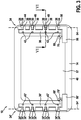
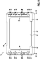
- housing 10 shown in Figs. 1 through 5 comprises a first housing part 14 and a second housing part 16.
- housing 10 is a housing for a patient monitor. Therefore, housing 10 further comprises an opening 18. This opening 18 may accommodate a display 20. Via this display 20 patient-relevant data, like but not limited to pulse, blood pressure, oxygen saturation of the blood, EKG- or EEG-data etc., may be displayed to the medical personal or a user in general. Accordingly, housing 10 may be used for a patient monitor device (now shown).
- first housing part 14 and second housing part 16 are held together via two locking mechanisms 24 and 24'.
- These locking mechanisms comprise basically the same elements, but are arranged on opposite sides.
- the explanations that follow for and in the context of locking mechanism 24 are correspondingly valid for the locking mechanism 24' shown in the respective figures.
- the same reference numerals are used for identical features only altered by an added prime (') after a reference numeral for clarity reasons.
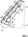
- the locking mechanism 24 comprises a locking element 26 which has in this embodiment four first engaging portions 28, 30, 32 and 34 arranged thereon.
- Locking element 26 is arranged on the first housing part 14.
- the locking element 26 is designed as a rigid element.
- an attaching element 36 is provided for arranging the locking element 26 on the first housing part 14 .
- the attaching element 36 comprises holders 38 for holding the locking element 26 between these holders 38 and a first inner wall 40 of first housing part 14.
- screws 42 are provided for attaching the attaching elements 36.
- other suitable attaching means may be used for attaching the attaching elements 36 to the first housing part 14, like but not limited to rivets, glue, latching mechanisms etc.
- the locking element 26 forms an integral part of the first housing part 14.
- second engaging portions 44, 46, 48 and 50 are arranged on an inner wall 52 of the second housing part 16, which will be explained in more detail later on.
- the locking element 26 is arranged rotatable on the first housing part 14. This rotation occurs along a rotating or pivot axis 54 as indicated in Fig. 3 . Via movement around this pivot axis 54 the locking element 26 undergoes a rotational movement along a predefined path.
- a handle 56 is provided on the locking element 26.
- the first housing part 14 also comprises an opening 57. Via this opening 57 the first housing part 14, and thereby the complete housing 10 may be attached to other devices, like a main unit (not shown) to which an exemplary patient monitor device belongs. Via this opening 57 the handle 56 may be easily accessible. However, other (small) openings may be provided in at least one of the sides of housing 10 in order to provide access to handle 56, especially in the absence of opening 57. Also, other ways of actuation may be used, like but not limited to magnetic or electronically controlled mechanisms, that do not need a direct access to handle 56.
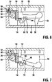
- Fig. 6 shows the locked or engaged state of the locking mechanism 24 wherein the first engaging portion 32 is in a releasable fit connection with the second engaging portion 48.
- first engaging portion 32 and second engaging portion 48 reference is only made to first engaging portion 32 and second engaging portion 48.
- all first engaging portions 28, 30, 32 and 34 are actuated and thereby brought in the releasable fit connection, i.e. in the engaged state, with the corresponding second engaging portions 44, 46, 48 and 50, respectively.
- first engaging portion 32 and second engaging portion 48 The releasable fit connection between first engaging portion 32 and second engaging portion 48 is realized by the first engaging portion 32 comprising a surface 58 and the second engaging portion 48 comprising a second surface 60. These surfaces 58 and 60 are preferably arranged parallel with respect to each other and get in direct contact such that the second housing part 16 is held strongly on the first housing part 14.
- a force acting on the engaging portions 32 and 48 as a result of any pull forces on the first and second housing parts 14 and 16 results in a force vector that is directed towards or goes through the pivot axis 54.
- the surfaces 58 and 60 are oriented in a way that an orthogonal vector of these surfaces 58 and 60 in the engaged state goes through or is directed towards the pivot axis 54 of the locking element 26.
- the last case can be regarded as identical to the afore-mentioned one, since a force acting on these engaging portions 32 and 48 could be represented by a vector that runs orthogonal to the surfaces 58 and 60 in the engaged state.
- the handle 56 has to be moved away from the second housing part 16, that is to say downwards with respect to the representation of Figs. 6 and 7 .
- This is illustrated in Fig. 6 by an arrow 62.
- a turning around pivot axis 54 occurs and the first engaging portion 32, as well as all the other first engaging portions 28, 30 and 34, moves out of the fit connection with the second engaging portion 48, or second engaging portions 44, 46 and 50.
- the first engaging portion 32 moves to the left or, with respect to the housing 10, inward.
- the end state of this disengagement is shown by the representation of Fig. 7 .
- the second housing part 16 can be easily removed from the first housing part 14.
- the handle 56 is moved towards the second housing part 16 or with respect to the representation of Figs. 6 and 7 upwards. This is indicated by an arrow 64. Thereby a rotation around pivot axis 54 occurs again such that the first engaging portions, like first engaging portion 32, are moved with respect to the housing 10 outwards or with respect to the representation of Fig. 7 to the right. Thereby, first engaging portion 32 gets (again) in a releasable fit connection with the second engaging portion 48.
- a holding mechanism 66 is further provided on the first housing part 14.
- the holding mechanism 66 is arranged on the attaching element 36.
- the holding mechanism 66 comprises a latching element 68, arranged on the attaching element 36, and a nose 70 arranged on handle 56.
- This latching element 68 is biased and can be bent such that the nose 70 may pass over this latching element 68.
- the latching element 68 bends towards the right with respect to the representation of Figs. 6 and 7 .
- this holding mechanism 66 further assists in the easy and fast opening and closing of the housing 10.
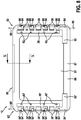
- FIGs. 8 and 9 show another exemplary embodiment of a housing according to the present invention, the housing 12. Therein, parts identical to housing 10 are designated by the same reference numerals and are not further explained in more detail.
- housing 12 comprises a first housing part 86 and a second housing part 96.
- First housing part 86 comprises a first inner wall 87
- second housing part 96 comprises a second inner wall 97.
- housing 12 comprises two types of locking mechanisms, locking mechanism 80 and locking mechanism 82. Whereas locking mechanism type 80 is brought into the locked or engaged state in the assembly process of joining the first housing part 86 and the second housing part 96, which will be explained later on in more detail, the second locking mechanism 82 is preferably actuated and brought into the locked or engaged state after the assembly of first housing part 86 and second housing part 96, similar to locking mechanism 24 of housing 10.
- housing 12 comprises two locking mechanisms 82 and 82'.
- those locking mechanisms 82 and 82' are comprised of the similar elements, such that the following explanations made for and in the context of locking mechanism 82 are correspondingly valid for the locking mechanism 82' shown in the respective figures.
- the same reference numerals are used for identical features only altered by an added prime (') after a reference numeral for clarity reasons.
- locking mechanism 24 locking mechanism 82 can be altered between an engaged and a disengaged state.
- the locking mechanism 82 comprises a locking element 84.
- Locking element 84 is arranged on the first housing part 86 of housing 12 via an attaching element 36 in this example. It goes without saying that even though the same attaching element 36 is used in housing 12 for attaching the locking element 84 on the first housing part 86 any other attaching element or attaching method may be used that is suitable for attaching the locking element 84 movably on this first housing part 86.
- the choice of the attaching element basically depends on the shape and design of the respective locking element 84.
- the locking element 84 is movable along a path that corresponds to the former pivot axis, i.e. longitudinally. In other words, the locking element 84 is able to undergo a translational movement. This is indicated by arrows 88 and 90 in Fig. 8 and also Fig. 9 .
- the locking element 84 comprises a handle 92. This handle 92 basically corresponds to handle 56 of locking element 26. Locking element 84 further comprises in this embodiment four first engaging portions 94.
- Second housing part 96 (not specifically shown in Figs. 8 and 9 ) comprises the second inner wall 97. On this inner wall 97 second engaging portions 98 are arranged.
- Fig. 8 shows the disengaged state of first engaging portions 94 and second engaging portions 98.
- first housing part 86 and second housing part 96 can easily be disassembled.
- Fig. 9 shows the engaged state.
- first engaging portions 94 lie with respect to the present representation above the second engaging portions 98. Thereby a fit connection of the engaging portions 94 and 98 is achieved and a disassembly of first housing part 86 and second housing part 96 is not possible.
- locking element 84 is moved in the direction of arrow 88. This can be done preferably by using handle 92. Thereby, first engaging portions 94 are moved correspondingly in this direction and engage with the corresponding second engaging portions 98.
- the disengaged state as shown in Fig. 8 is achieved again by movement of the locking element 84 in the direction of arrow 90. This is preferably done again by using handle 92. As a result, first engaging portions 94 and second engaging portions 98 get disengaged and a disassembly of housing 12 is possible.
- first engaging portions 94 and second engaging portions 98 may be for example identical to the shape of first engaging portions 28, 30, 32 and 34 and second engaging portions 44, 46, 48 and 50, respectively. However, any other suitable shape for these first and second engaging portions 94 and 98 may be chosen as long as a reliable locking of first and second housing part 86 and 96 is achieved.
- Fig. 10 shows a simple representation of the locking mechanism 80 as already mentioned in the context of Fig. 8 .
- This locking mechanism 80 comprises a tongue 100 forming a third engaging portion and a groove 102 forming a fourth engaging portion.
- the tongue 100 is arranged on the first inner wall 87 of the first housing part 86 whereas the groove 102 is arranged on the second inner wall 97 of the second housing part 96.
- the locking state of this locking mechanism 80 is achieved by joining first housing part 86 and second housing part 96 in a way, possibly in a slightly angled way such that tongue 100 enters groove 102.
- housing 12 is shown with another locking mechanism 80 aside from the actuatable locking mechanism 82 it goes without saying that also the embodiment of the locking mechanism shown for housing 10 in Figs. 1 through 7 may be equipped with a locking mechanism identical or similar to locking mechanism 80. Further, aside from this static locking mechanism 80, housings may be provided with another actuatable locking mechanism, like locking mechanisms 24 and 82, instead of locking mechanism 80 or even with an actuatable locking mechanism present on every possible side of the housing.
Landscapes
- Engineering & Computer Science (AREA)
- Theoretical Computer Science (AREA)
- General Engineering & Computer Science (AREA)
- Computer Hardware Design (AREA)
- Human Computer Interaction (AREA)
- Physics & Mathematics (AREA)
- General Physics & Mathematics (AREA)
- Microelectronics & Electronic Packaging (AREA)
- Casings For Electric Apparatus (AREA)
Applications Claiming Priority (2)
| Application Number | Priority Date | Filing Date | Title |
|---|---|---|---|
| US201261708725P | 2012-10-02 | 2012-10-02 | |
| PCT/IB2013/058414 WO2014053926A1 (en) | 2012-10-02 | 2013-09-10 | Housing with releasable locking element |
Publications (2)
| Publication Number | Publication Date |
|---|---|
| EP2904885A1 EP2904885A1 (en) | 2015-08-12 |
| EP2904885B1 true EP2904885B1 (en) | 2017-07-12 |
Family
ID=49713419
Family Applications (1)
| Application Number | Title | Priority Date | Filing Date |
|---|---|---|---|
| EP13799674.0A Active EP2904885B1 (en) | 2012-10-02 | 2013-09-10 | Housing with releasable locking element |
Country Status (6)
| Country | Link |
|---|---|
| US (1) | US9606575B2 (enExample) |
| EP (1) | EP2904885B1 (enExample) |
| JP (1) | JP6249535B2 (enExample) |
| CN (1) | CN104718805B (enExample) |
| BR (1) | BR112015007075A2 (enExample) |
| WO (1) | WO2014053926A1 (enExample) |
Families Citing this family (9)
| Publication number | Priority date | Publication date | Assignee | Title |
|---|---|---|---|---|
| JP6361623B2 (ja) * | 2015-10-05 | 2018-07-25 | 株式会社デンソー | 固定装置 |
| US9668371B1 (en) * | 2016-04-12 | 2017-05-30 | Dell Products L.P. | Systems and methods for securing panels to information handling system chassis |
| USD823264S1 (en) * | 2016-10-27 | 2018-07-17 | Universal Electronics Inc. | Remote control housing |
| USD825494S1 (en) * | 2016-10-27 | 2018-08-14 | Universal Electronics Inc. | Remote control housing |
| EP3648558A1 (en) | 2018-11-05 | 2020-05-06 | Koninklijke Philips N.V. | Housing with internal locking arrangement |
| JP6779342B1 (ja) * | 2019-06-07 | 2020-11-04 | レノボ・シンガポール・プライベート・リミテッド | 電子機器用筐体及び電子機器 |
| WO2023134870A1 (en) * | 2022-01-17 | 2023-07-20 | Huawei Technologies Co., Ltd. | Locking arrangement for smart device housing |
| JP7571165B2 (ja) * | 2023-01-13 | 2024-10-22 | レノボ・シンガポール・プライベート・リミテッド | 電子機器筐体及び電子機器 |
| EP4660745A1 (en) | 2024-06-05 | 2025-12-10 | Koninklijke Philips N.V. | Housing face panel arrangement and medical device |
Family Cites Families (16)
| Publication number | Priority date | Publication date | Assignee | Title |
|---|---|---|---|---|
| US4077515A (en) | 1976-10-06 | 1978-03-07 | Dell Shoberg | Medical slide case with hinged molded sections |
| JPS62296U (enExample) * | 1985-06-12 | 1987-01-06 | ||
| IT1267973B1 (it) * | 1994-01-13 | 1997-02-20 | Olivetti & Co Spa | Carrozzeria per apparecchiature elettroniche quali calcolatori personali e/o loro periferiche |
| JP3338739B2 (ja) * | 1995-05-12 | 2002-10-28 | アンリツ株式会社 | 電磁波シールドボックス |
| US6440076B1 (en) | 2000-11-09 | 2002-08-27 | Koninklijke Philips Electronics N.V. | Ultrasound transducer connector assembly |
| US7609512B2 (en) * | 2001-11-19 | 2009-10-27 | Otter Products, Llc | Protective enclosure for electronic device |
| US7924553B2 (en) * | 2005-03-09 | 2011-04-12 | Hewlett-Packard Development Company, L.P. | Computer device locking system |
| US7349199B2 (en) * | 2005-06-17 | 2008-03-25 | Hewlett-Packard Development Company, L.P. | Computer device display protector |
| CN2842533Y (zh) * | 2005-06-22 | 2006-11-29 | 鸿富锦精密工业(深圳)有限公司 | 电脑盖板锁固装置 |
| CN101873777B (zh) * | 2009-04-27 | 2014-11-05 | 鸿富锦精密工业(深圳)有限公司 | 机箱 |
| CN101932216A (zh) * | 2009-06-18 | 2010-12-29 | 鸿富锦精密工业(深圳)有限公司 | 门盖装置 |
| US8074390B2 (en) | 2009-07-06 | 2011-12-13 | Michele Trevison Rain | Display box |
| US8233272B2 (en) * | 2009-08-25 | 2012-07-31 | Mindray Ds Usa, Inc. | Display units for use in monitoring patients and related systems and methods |
| JP2011091078A (ja) * | 2009-10-20 | 2011-05-06 | Nec Corp | 筐体の連結構造 |
| WO2012063160A1 (en) | 2010-11-11 | 2012-05-18 | Koninklijke Philips Electronics N.V. | Carrying case with improved access for defibrillator and accessories |
| US9345153B2 (en) * | 2011-02-24 | 2016-05-17 | Nec Corporation | Electronic device |
-
2013
- 2013-09-10 US US14/432,493 patent/US9606575B2/en active Active
- 2013-09-10 EP EP13799674.0A patent/EP2904885B1/en active Active
- 2013-09-10 WO PCT/IB2013/058414 patent/WO2014053926A1/en not_active Ceased
- 2013-09-10 BR BR112015007075A patent/BR112015007075A2/pt not_active Application Discontinuation
- 2013-09-10 CN CN201380051901.7A patent/CN104718805B/zh active Active
- 2013-09-10 JP JP2015535126A patent/JP6249535B2/ja active Active
Non-Patent Citations (1)
| Title |
|---|
| None * |
Also Published As
| Publication number | Publication date |
|---|---|
| WO2014053926A1 (en) | 2014-04-10 |
| JP2015534276A (ja) | 2015-11-26 |
| CN104718805B (zh) | 2017-09-15 |
| EP2904885A1 (en) | 2015-08-12 |
| BR112015007075A2 (pt) | 2017-07-04 |
| US9606575B2 (en) | 2017-03-28 |
| CN104718805A (zh) | 2015-06-17 |
| JP6249535B2 (ja) | 2017-12-20 |
| US20150277487A1 (en) | 2015-10-01 |
Similar Documents
| Publication | Publication Date | Title |
|---|---|---|
| EP2904885B1 (en) | Housing with releasable locking element | |
| US20240366859A1 (en) | Self-compensating chucking device for infusion pump systems | |
| CN108138825A (zh) | 用于家具和家居用品的部件的具有广泛可及性的接合装置 | |
| EP4102013B1 (en) | Latch assembly | |
| US9363908B1 (en) | Latch device and server using the same | |
| JP6616139B2 (ja) | 医用ペリスタポンプ | |
| US20210244441A1 (en) | Seal cartridge latch design for trocar assemblies | |
| US10551070B2 (en) | Home appliance | |
| TWI708884B (zh) | 按拉式閂鎖裝置 | |
| TWI732257B (zh) | 推拉桿模組 | |
| US10265233B2 (en) | Incubator | |
| CA2512957C (en) | Common lock for dual-usage portable computer | |
| JP5444281B2 (ja) | ダイヤル錠ユニット | |
| KR101260682B1 (ko) | 다점 조임 방식 로킹 장치 | |
| JP7487190B2 (ja) | 内部ロック構成を備えた筐体 | |
| US10986747B2 (en) | Fixing assembly, casing assembly, and electronic device | |
| JP4573199B2 (ja) | ファスナーの引手装置 | |
| CN113991566B (zh) | 锁盖组件和盒子 | |
| TWI604118B (zh) | 撥號環及撥號鎖 | |
| TW201622523A (zh) | 閂鎖裝置及採用該閂鎖裝置的伺服器 | |
| RU2511561C1 (ru) | Запирающее устройство для двери | |
| TWM474787U (zh) | 用於驅動鎖閂裝置的推拉式操作裝置 |
Legal Events
| Date | Code | Title | Description |
|---|---|---|---|
| PUAI | Public reference made under article 153(3) epc to a published international application that has entered the european phase |
Free format text: ORIGINAL CODE: 0009012 |
|
| 17P | Request for examination filed |
Effective date: 20150504 |
|
| AK | Designated contracting states |
Kind code of ref document: A1 Designated state(s): AL AT BE BG CH CY CZ DE DK EE ES FI FR GB GR HR HU IE IS IT LI LT LU LV MC MK MT NL NO PL PT RO RS SE SI SK SM TR |
|
| AX | Request for extension of the european patent |
Extension state: BA ME |
|
| DAX | Request for extension of the european patent (deleted) | ||
| GRAP | Despatch of communication of intention to grant a patent |
Free format text: ORIGINAL CODE: EPIDOSNIGR1 |
|
| INTG | Intention to grant announced |
Effective date: 20170209 |
|
| GRAS | Grant fee paid |
Free format text: ORIGINAL CODE: EPIDOSNIGR3 |
|
| GRAA | (expected) grant |
Free format text: ORIGINAL CODE: 0009210 |
|
| AK | Designated contracting states |
Kind code of ref document: B1 Designated state(s): AL AT BE BG CH CY CZ DE DK EE ES FI FR GB GR HR HU IE IS IT LI LT LU LV MC MK MT NL NO PL PT RO RS SE SI SK SM TR |
|
| REG | Reference to a national code |
Ref country code: GB Ref legal event code: FG4D |
|
| REG | Reference to a national code |
Ref country code: CH Ref legal event code: EP |
|
| REG | Reference to a national code |
Ref country code: AT Ref legal event code: REF Ref document number: 909438 Country of ref document: AT Kind code of ref document: T Effective date: 20170715 |
|
| REG | Reference to a national code |
Ref country code: IE Ref legal event code: FG4D |
|
| REG | Reference to a national code |
Ref country code: DE Ref legal event code: R096 Ref document number: 602013023515 Country of ref document: DE |
|
| REG | Reference to a national code |
Ref country code: FR Ref legal event code: PLFP Year of fee payment: 5 |
|
| REG | Reference to a national code |
Ref country code: NL Ref legal event code: MP Effective date: 20170712 |
|
| REG | Reference to a national code |
Ref country code: LT Ref legal event code: MG4D |
|
| REG | Reference to a national code |
Ref country code: AT Ref legal event code: MK05 Ref document number: 909438 Country of ref document: AT Kind code of ref document: T Effective date: 20170712 |
|
| PG25 | Lapsed in a contracting state [announced via postgrant information from national office to epo] |
Ref country code: HR Free format text: LAPSE BECAUSE OF FAILURE TO SUBMIT A TRANSLATION OF THE DESCRIPTION OR TO PAY THE FEE WITHIN THE PRESCRIBED TIME-LIMIT Effective date: 20170712 Ref country code: LT Free format text: LAPSE BECAUSE OF FAILURE TO SUBMIT A TRANSLATION OF THE DESCRIPTION OR TO PAY THE FEE WITHIN THE PRESCRIBED TIME-LIMIT Effective date: 20170712 Ref country code: AT Free format text: LAPSE BECAUSE OF FAILURE TO SUBMIT A TRANSLATION OF THE DESCRIPTION OR TO PAY THE FEE WITHIN THE PRESCRIBED TIME-LIMIT Effective date: 20170712 Ref country code: FI Free format text: LAPSE BECAUSE OF FAILURE TO SUBMIT A TRANSLATION OF THE DESCRIPTION OR TO PAY THE FEE WITHIN THE PRESCRIBED TIME-LIMIT Effective date: 20170712 Ref country code: NL Free format text: LAPSE BECAUSE OF FAILURE TO SUBMIT A TRANSLATION OF THE DESCRIPTION OR TO PAY THE FEE WITHIN THE PRESCRIBED TIME-LIMIT Effective date: 20170712 Ref country code: SE Free format text: LAPSE BECAUSE OF FAILURE TO SUBMIT A TRANSLATION OF THE DESCRIPTION OR TO PAY THE FEE WITHIN THE PRESCRIBED TIME-LIMIT Effective date: 20170712 Ref country code: NO Free format text: LAPSE BECAUSE OF FAILURE TO SUBMIT A TRANSLATION OF THE DESCRIPTION OR TO PAY THE FEE WITHIN THE PRESCRIBED TIME-LIMIT Effective date: 20171012 |
|
| PG25 | Lapsed in a contracting state [announced via postgrant information from national office to epo] |
Ref country code: GR Free format text: LAPSE BECAUSE OF FAILURE TO SUBMIT A TRANSLATION OF THE DESCRIPTION OR TO PAY THE FEE WITHIN THE PRESCRIBED TIME-LIMIT Effective date: 20171013 Ref country code: RS Free format text: LAPSE BECAUSE OF FAILURE TO SUBMIT A TRANSLATION OF THE DESCRIPTION OR TO PAY THE FEE WITHIN THE PRESCRIBED TIME-LIMIT Effective date: 20170712 Ref country code: ES Free format text: LAPSE BECAUSE OF FAILURE TO SUBMIT A TRANSLATION OF THE DESCRIPTION OR TO PAY THE FEE WITHIN THE PRESCRIBED TIME-LIMIT Effective date: 20170712 Ref country code: LV Free format text: LAPSE BECAUSE OF FAILURE TO SUBMIT A TRANSLATION OF THE DESCRIPTION OR TO PAY THE FEE WITHIN THE PRESCRIBED TIME-LIMIT Effective date: 20170712 Ref country code: IS Free format text: LAPSE BECAUSE OF FAILURE TO SUBMIT A TRANSLATION OF THE DESCRIPTION OR TO PAY THE FEE WITHIN THE PRESCRIBED TIME-LIMIT Effective date: 20171112 Ref country code: PL Free format text: LAPSE BECAUSE OF FAILURE TO SUBMIT A TRANSLATION OF THE DESCRIPTION OR TO PAY THE FEE WITHIN THE PRESCRIBED TIME-LIMIT Effective date: 20170712 Ref country code: BG Free format text: LAPSE BECAUSE OF FAILURE TO SUBMIT A TRANSLATION OF THE DESCRIPTION OR TO PAY THE FEE WITHIN THE PRESCRIBED TIME-LIMIT Effective date: 20171012 |
|
| REG | Reference to a national code |
Ref country code: DE Ref legal event code: R097 Ref document number: 602013023515 Country of ref document: DE |
|
| PG25 | Lapsed in a contracting state [announced via postgrant information from national office to epo] |
Ref country code: RO Free format text: LAPSE BECAUSE OF FAILURE TO SUBMIT A TRANSLATION OF THE DESCRIPTION OR TO PAY THE FEE WITHIN THE PRESCRIBED TIME-LIMIT Effective date: 20170712 Ref country code: CZ Free format text: LAPSE BECAUSE OF FAILURE TO SUBMIT A TRANSLATION OF THE DESCRIPTION OR TO PAY THE FEE WITHIN THE PRESCRIBED TIME-LIMIT Effective date: 20170712 Ref country code: DK Free format text: LAPSE BECAUSE OF FAILURE TO SUBMIT A TRANSLATION OF THE DESCRIPTION OR TO PAY THE FEE WITHIN THE PRESCRIBED TIME-LIMIT Effective date: 20170712 |
|
| REG | Reference to a national code |
Ref country code: CH Ref legal event code: PL |
|
| PLBE | No opposition filed within time limit |
Free format text: ORIGINAL CODE: 0009261 |
|
| STAA | Information on the status of an ep patent application or granted ep patent |
Free format text: STATUS: NO OPPOSITION FILED WITHIN TIME LIMIT |
|
| PG25 | Lapsed in a contracting state [announced via postgrant information from national office to epo] |
Ref country code: IT Free format text: LAPSE BECAUSE OF FAILURE TO SUBMIT A TRANSLATION OF THE DESCRIPTION OR TO PAY THE FEE WITHIN THE PRESCRIBED TIME-LIMIT Effective date: 20170712 Ref country code: MC Free format text: LAPSE BECAUSE OF FAILURE TO SUBMIT A TRANSLATION OF THE DESCRIPTION OR TO PAY THE FEE WITHIN THE PRESCRIBED TIME-LIMIT Effective date: 20170712 Ref country code: EE Free format text: LAPSE BECAUSE OF FAILURE TO SUBMIT A TRANSLATION OF THE DESCRIPTION OR TO PAY THE FEE WITHIN THE PRESCRIBED TIME-LIMIT Effective date: 20170712 Ref country code: SK Free format text: LAPSE BECAUSE OF FAILURE TO SUBMIT A TRANSLATION OF THE DESCRIPTION OR TO PAY THE FEE WITHIN THE PRESCRIBED TIME-LIMIT Effective date: 20170712 Ref country code: SM Free format text: LAPSE BECAUSE OF FAILURE TO SUBMIT A TRANSLATION OF THE DESCRIPTION OR TO PAY THE FEE WITHIN THE PRESCRIBED TIME-LIMIT Effective date: 20170712 |
|
| 26N | No opposition filed |
Effective date: 20180413 |
|
| REG | Reference to a national code |
Ref country code: IE Ref legal event code: MM4A |
|
| REG | Reference to a national code |
Ref country code: BE Ref legal event code: MM Effective date: 20170930 |
|
| PG25 | Lapsed in a contracting state [announced via postgrant information from national office to epo] |
Ref country code: LU Free format text: LAPSE BECAUSE OF NON-PAYMENT OF DUE FEES Effective date: 20170910 |
|
| PG25 | Lapsed in a contracting state [announced via postgrant information from national office to epo] |
Ref country code: IE Free format text: LAPSE BECAUSE OF NON-PAYMENT OF DUE FEES Effective date: 20170910 Ref country code: LI Free format text: LAPSE BECAUSE OF NON-PAYMENT OF DUE FEES Effective date: 20170930 Ref country code: CH Free format text: LAPSE BECAUSE OF NON-PAYMENT OF DUE FEES Effective date: 20170930 |
|
| PG25 | Lapsed in a contracting state [announced via postgrant information from national office to epo] |
Ref country code: SI Free format text: LAPSE BECAUSE OF FAILURE TO SUBMIT A TRANSLATION OF THE DESCRIPTION OR TO PAY THE FEE WITHIN THE PRESCRIBED TIME-LIMIT Effective date: 20170712 Ref country code: BE Free format text: LAPSE BECAUSE OF NON-PAYMENT OF DUE FEES Effective date: 20170930 |
|
| REG | Reference to a national code |
Ref country code: FR Ref legal event code: PLFP Year of fee payment: 6 |
|
| PG25 | Lapsed in a contracting state [announced via postgrant information from national office to epo] |
Ref country code: MT Free format text: LAPSE BECAUSE OF NON-PAYMENT OF DUE FEES Effective date: 20170910 |
|
| PG25 | Lapsed in a contracting state [announced via postgrant information from national office to epo] |
Ref country code: HU Free format text: LAPSE BECAUSE OF FAILURE TO SUBMIT A TRANSLATION OF THE DESCRIPTION OR TO PAY THE FEE WITHIN THE PRESCRIBED TIME-LIMIT; INVALID AB INITIO Effective date: 20130910 |
|
| PG25 | Lapsed in a contracting state [announced via postgrant information from national office to epo] |
Ref country code: CY Free format text: LAPSE BECAUSE OF FAILURE TO SUBMIT A TRANSLATION OF THE DESCRIPTION OR TO PAY THE FEE WITHIN THE PRESCRIBED TIME-LIMIT Effective date: 20170712 |
|
| PG25 | Lapsed in a contracting state [announced via postgrant information from national office to epo] |
Ref country code: MK Free format text: LAPSE BECAUSE OF FAILURE TO SUBMIT A TRANSLATION OF THE DESCRIPTION OR TO PAY THE FEE WITHIN THE PRESCRIBED TIME-LIMIT Effective date: 20170712 |
|
| PG25 | Lapsed in a contracting state [announced via postgrant information from national office to epo] |
Ref country code: TR Free format text: LAPSE BECAUSE OF FAILURE TO SUBMIT A TRANSLATION OF THE DESCRIPTION OR TO PAY THE FEE WITHIN THE PRESCRIBED TIME-LIMIT Effective date: 20170712 |
|
| PG25 | Lapsed in a contracting state [announced via postgrant information from national office to epo] |
Ref country code: PT Free format text: LAPSE BECAUSE OF FAILURE TO SUBMIT A TRANSLATION OF THE DESCRIPTION OR TO PAY THE FEE WITHIN THE PRESCRIBED TIME-LIMIT Effective date: 20170712 |
|
| PG25 | Lapsed in a contracting state [announced via postgrant information from national office to epo] |
Ref country code: AL Free format text: LAPSE BECAUSE OF FAILURE TO SUBMIT A TRANSLATION OF THE DESCRIPTION OR TO PAY THE FEE WITHIN THE PRESCRIBED TIME-LIMIT Effective date: 20170712 |
|
| PGFP | Annual fee paid to national office [announced via postgrant information from national office to epo] |
Ref country code: DE Payment date: 20250926 Year of fee payment: 13 |
|
| PGFP | Annual fee paid to national office [announced via postgrant information from national office to epo] |
Ref country code: GB Payment date: 20250923 Year of fee payment: 13 |
|
| PGFP | Annual fee paid to national office [announced via postgrant information from national office to epo] |
Ref country code: FR Payment date: 20250925 Year of fee payment: 13 |