EP2904252B1 - Statische leitschaufel mit internen hohlen kanälen - Google Patents
Statische leitschaufel mit internen hohlen kanälen Download PDFInfo
- Publication number
- EP2904252B1 EP2904252B1 EP13843942.7A EP13843942A EP2904252B1 EP 2904252 B1 EP2904252 B1 EP 2904252B1 EP 13843942 A EP13843942 A EP 13843942A EP 2904252 B1 EP2904252 B1 EP 2904252B1
- Authority
- EP
- European Patent Office
- Prior art keywords
- static guide
- guide vane
- channels
- fan
- airfoil
- Prior art date
- Legal status (The legal status is an assumption and is not a legal conclusion. Google has not performed a legal analysis and makes no representation as to the accuracy of the status listed.)
- Active
Links
- 230000003068 static effect Effects 0.000 title claims description 22
- 239000000446 fuel Substances 0.000 description 5
- 239000000853 adhesive Substances 0.000 description 1
- 230000001070 adhesive effect Effects 0.000 description 1
- 238000002485 combustion reaction Methods 0.000 description 1
- 230000006835 compression Effects 0.000 description 1
- 238000007906 compression Methods 0.000 description 1
- 230000003247 decreasing effect Effects 0.000 description 1
- 238000012986 modification Methods 0.000 description 1
- 230000004048 modification Effects 0.000 description 1
Images

Classifications
-
- F—MECHANICAL ENGINEERING; LIGHTING; HEATING; WEAPONS; BLASTING
- F01—MACHINES OR ENGINES IN GENERAL; ENGINE PLANTS IN GENERAL; STEAM ENGINES
- F01D—NON-POSITIVE DISPLACEMENT MACHINES OR ENGINES, e.g. STEAM TURBINES
- F01D5/00—Blades; Blade-carrying members; Heating, heat-insulating, cooling or antivibration means on the blades or the members
- F01D5/12—Blades
- F01D5/14—Form or construction
- F01D5/147—Construction, i.e. structural features, e.g. of weight-saving hollow blades
-
- F—MECHANICAL ENGINEERING; LIGHTING; HEATING; WEAPONS; BLASTING
- F01—MACHINES OR ENGINES IN GENERAL; ENGINE PLANTS IN GENERAL; STEAM ENGINES
- F01D—NON-POSITIVE DISPLACEMENT MACHINES OR ENGINES, e.g. STEAM TURBINES
- F01D9/00—Stators
- F01D9/02—Nozzles; Nozzle boxes; Stator blades; Guide conduits, e.g. individual nozzles
-
- F—MECHANICAL ENGINEERING; LIGHTING; HEATING; WEAPONS; BLASTING
- F01—MACHINES OR ENGINES IN GENERAL; ENGINE PLANTS IN GENERAL; STEAM ENGINES
- F01D—NON-POSITIVE DISPLACEMENT MACHINES OR ENGINES, e.g. STEAM TURBINES
- F01D1/00—Non-positive-displacement machines or engines, e.g. steam turbines
- F01D1/02—Non-positive-displacement machines or engines, e.g. steam turbines with stationary working-fluid guiding means and bladed or like rotor, e.g. multi-bladed impulse steam turbines
-
- F—MECHANICAL ENGINEERING; LIGHTING; HEATING; WEAPONS; BLASTING
- F01—MACHINES OR ENGINES IN GENERAL; ENGINE PLANTS IN GENERAL; STEAM ENGINES
- F01D—NON-POSITIVE DISPLACEMENT MACHINES OR ENGINES, e.g. STEAM TURBINES
- F01D9/00—Stators
- F01D9/02—Nozzles; Nozzle boxes; Stator blades; Guide conduits, e.g. individual nozzles
- F01D9/04—Nozzles; Nozzle boxes; Stator blades; Guide conduits, e.g. individual nozzles forming ring or sector
- F01D9/041—Nozzles; Nozzle boxes; Stator blades; Guide conduits, e.g. individual nozzles forming ring or sector using blades
-
- F—MECHANICAL ENGINEERING; LIGHTING; HEATING; WEAPONS; BLASTING
- F05—INDEXING SCHEMES RELATING TO ENGINES OR PUMPS IN VARIOUS SUBCLASSES OF CLASSES F01-F04
- F05D—INDEXING SCHEME FOR ASPECTS RELATING TO NON-POSITIVE-DISPLACEMENT MACHINES OR ENGINES, GAS-TURBINES OR JET-PROPULSION PLANTS
- F05D2230/00—Manufacture
- F05D2230/20—Manufacture essentially without removing material
- F05D2230/23—Manufacture essentially without removing material by permanently joining parts together
-
- F—MECHANICAL ENGINEERING; LIGHTING; HEATING; WEAPONS; BLASTING
- F05—INDEXING SCHEMES RELATING TO ENGINES OR PUMPS IN VARIOUS SUBCLASSES OF CLASSES F01-F04
- F05D—INDEXING SCHEME FOR ASPECTS RELATING TO NON-POSITIVE-DISPLACEMENT MACHINES OR ENGINES, GAS-TURBINES OR JET-PROPULSION PLANTS
- F05D2240/00—Components
- F05D2240/10—Stators
- F05D2240/12—Fluid guiding means, e.g. vanes
-
- Y—GENERAL TAGGING OF NEW TECHNOLOGICAL DEVELOPMENTS; GENERAL TAGGING OF CROSS-SECTIONAL TECHNOLOGIES SPANNING OVER SEVERAL SECTIONS OF THE IPC; TECHNICAL SUBJECTS COVERED BY FORMER USPC CROSS-REFERENCE ART COLLECTIONS [XRACs] AND DIGESTS
- Y02—TECHNOLOGIES OR APPLICATIONS FOR MITIGATION OR ADAPTATION AGAINST CLIMATE CHANGE
- Y02T—CLIMATE CHANGE MITIGATION TECHNOLOGIES RELATED TO TRANSPORTATION
- Y02T50/00—Aeronautics or air transport
- Y02T50/60—Efficient propulsion technologies, e.g. for aircraft
Definitions
- This application relates to a static guide vane which is provided with hollow channels to reduce weight.
- Gas turbine engines typically include a fan delivering air into a compressor.
- the air is compressed and passed into a combustor section where it is mixed with fuel and ignited.
- Products of the combustion pass downstream over turbine rotors, driving them to rotate.
- the turbine rotors in turn, drive compressor and fan rotors.
- a low pressure turbine would drive a low pressure compressor and the fan as one spool. Thus, all three components rotated at a common speed. More recently, it has been proposed to include a gear reduction between the fan and the low pressure turbine. With the use of the gear reduction, the fan can rotate at a slower speed than the low pressure turbine or the low pressure compressor.
- the diameter of the fan could be increased.
- the fan typically also delivers air into a bypass duct where it becomes propulsion for an aircraft receiving the gas turbine engine. As the fan diameter has increased, so has the amount of bypass air.
- EP 1596036 discloses a prior art static guide vane in accordance with the precharacterising portion of claim 1.
- the ribs and portions of a recess between the channels and the trailing and leading edges together form a planar surface for supporting the cover.
- the channels extend for a greater width, with the width defined between the leading and trailing edges, as the channels approach the trailing edge.
- a feature ensures that the cover is an appropriate cover for the particular static guide vane.
- the invention also extends to a fan section as set forth in claim 6.
- the invention also extends to a gas turbine engine as set forth in claim 7.
- FIG. 1 schematically illustrates a gas turbine engine 20.
- the gas turbine engine 20 is disclosed herein as a two-spool turbofan that generally incorporates a fan section 22, a compressor section 24, a combustor section 26 and a turbine section 28.
- Alternative engines might include an augmentor section (not shown) among other systems or features.
- the fan section 22 drives air along a bypass flow path B in a bypass duct defined within a nacelle 15, while the compressor section 24 drives air along a core flow path C for compression and communication into the combustor section 26 then expansion through the turbine section 28.
- FIG. 1 schematically illustrates a gas turbine engine 20.
- the gas turbine engine 20 is disclosed herein as a two-spool turbofan that generally incorporates a fan section 22, a compressor section 24, a combustor section 26 and a turbine section 28.
- Alternative engines might include an augmentor section (not shown) among other systems or features.
- the fan section 22 drives air along a bypass flow path B in a bypass duct defined within
- the engine 20 generally includes a low speed spool 30 and a high speed spool 32 mounted for rotation about an engine central longitudinal axis A relative to an engine static structure 36 via several bearing systems 38. It should be understood that various bearing systems 38 at various locations may alternatively or additionally be provided.
- the low speed spool 30 generally includes an inner shaft 40 that interconnects a fan 42, a low pressure compressor 44 and a low pressure turbine 46.
- the inner shaft 40 is connected to the fan 42 through a geared architecture 48 to drive the fan 42 at a lower speed than the low speed spool 30.
- the high speed spool 32 includes an outer shaft 50 that interconnects a high pressure compressor 52 and high pressure turbine 54.
- a combustor 56 is arranged between the high pressure compressor 52 and the high pressure turbine 54.
- a mid-turbine frame 57 of the engine static structure 36 is arranged generally between the high pressure turbine 54 and the low pressure turbine 46.
- the mid-turbine frame 57 further supports bearing systems 38 in the turbine section 28.
- the inner shaft 40 and the outer shaft 50 are concentric and rotate via bearing systems 38 about the engine central longitudinal axis A which is collinear with their longitudinal axes.
- the core airflow is compressed by the low pressure compressor 44 then the high pressure compressor 52, mixed and burned with fuel in the combustor 56, then expanded over the high pressure turbine 54 and low pressure turbine 46.
- the mid-turbine frame 57 includes airfoils 59 which are in the core airflow path.
- the turbines 46, 54 rotationally drive the respective low speed spool 30 and high speed spool 32 in response to the expansion.
- the engine 20 in one example is a high-bypass geared aircraft engine.
- the engine 20 bypass ratio is greater than about six (6), with an example embodiment being greater than ten (10)
- the geared architecture 48 is an epicyclic gear train, such as a planetary gear system or other gear system, with a gear reduction ratio of greater than about 2.3 and the low pressure turbine 46 has a pressure ratio that is greater than about five (5).
- the engine 20 bypass ratio is greater than about ten (10:1)
- the fan diameter is significantly larger than that of the low pressure compressor 44
- the low pressure turbine 46 has a pressure ratio that is greater than about five (5:1).
- Low pressure turbine 46 pressure ratio is pressure measured prior to inlet of low pressure turbine 46 as related to the pressure at the outlet of the low pressure turbine 46 prior to an exhaust nozzle.
- the geared architecture 48 may be an epicycle gear train, such as a planetary gear system or other gear system, with a gear reduction ratio of greater than about 2.5:1. It should be understood, however, that the above parameters are only exemplary of one embodiment of a geared architecture engine and that the present invention is applicable to other gas turbine engines including direct drive turbofans.
- the fan section 22 of the engine 20 is designed for a particular flight condition -- typically cruise at about 0.8 Mach and about 35,000 feet.
- the flight condition of 0.8 Mach and 35,000 ft, with the engine at its best fuel consumption - also known as "bucket cruise Thrust Specific Fuel Consumption ('TSFC')" - is the industry standard parameter of lbm of fuel being burned divided by lbf of thrust the engine produces at that minimum point.
- "Low fan pressure ratio” is the pressure ratio across the fan blade alone, without a Fan Exit Guide Vane (“FEGV”) system.
- the low fan pressure ratio as disclosed herein according to one non-limiting embodiment is less than about 1.45.
- Low corrected fan tip speed is the actual fan tip speed in ft/sec divided by an industry standard temperature correction of [(Tram °R) / (518.7 °R)] 0.5 .
- the "Low corrected fan tip speed” as disclosed herein according to one non-limiting embodiment is less than about 1150 ft / second.
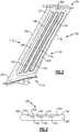
- FIG 2 shows a static guide vane 100, which is positioned downstream of a fan rotor, such as fan rotor 42 as shown in Figure 1 .
- An outer platform mount 105 is connected by an airfoil 110 to an inner platform mount 115.
- the static guide vane 100 has a leading edge 160 and a trailing edge 150.
- the cover 200 may be secured such as by adhesive to a main body 201 of the vane 100.
- FIG. 2 and 3 there are three channels 128, 130 and 135 spaced in a direction from the leading edge 160 toward the trailing edge 150. There are also intermediate ribs 140 and 145 intermediate the channels. An outer surface of ribs 140 and 145 define a parallel plane with surfaces 165 and 155 of the recess to support the cover 200.
- the width of the channels 128, 130, 135 defined in a direction from the leading edge 160 toward the trailing edge 150 increases as the channels approach the trailing edge 150.
- the ribs will provide structural support to the vane 100 while the channels 128, 130 and 135 reduce the overall weight.
- a "fool-proofing" notch 300 will ensure that the cover 200 which is mounted on a static guide vane 100 will be an appropriate cover.
Landscapes
- Engineering & Computer Science (AREA)
- Mechanical Engineering (AREA)
- General Engineering & Computer Science (AREA)
- Architecture (AREA)
- Structures Of Non-Positive Displacement Pumps (AREA)
Claims (8)
- Statische Leitschaufel (100) für einen Gasturbinentriebwerk (20), umfassend:eine äußere Plattform (105) und eine innere Plattform (115), wobei die innere und äußere Plattform (105, 115) durch ein Schaufelblatt (110) verbunden sind; undwobei das Schaufelblatt (110) Kanäle (128, 130, 135), die sich in einen Hauptkörper (201) des Schaufelblatts (110) erstrecken, und eine Abdeckung (200) aufweist, die die Kanäle (128, 130, 135) verschließt, wobei die Abdeckung (200) einen Abschnitt des Schaufelblatts (110) bereitstellt, wobei eine Vielzahl der Kanäle (128, 130, 135) vorliegt, die sich in eine allgemein radiale Richtung von der inneren Plattform (115) zur äußeren Plattform (105) erstreckt und von einer Vorderkante (160) des Schaufelblatts (110) zu einer Hinterkante (150) des Schaufelblatts (110) beabstandet ist;dadurch gekennzeichnet, dass:die Kanäle (128, 130, 135) sich über eine größere Breite erstrecken, wobei die Breite zwischen der Vorder- und Hinterkante (160, 150) definiert ist, wenn sich die Kanäle (128, 130, 135) der Hinterkante (150) annähern.
- Statische Leitschaufel (100) nach Anspruch 1, wobei Rippen (140, 145) zwischen der Vielzahl von Kanälen (128, 130, 135) vorliegen.
- Statische Leitschaufel (100) nach Anspruch 2, wobei die Rippen (140, 145) und Abschnitte einer Vertiefung (155, 165) zwischen den Kanälen (128, 130, 135) und der Hinter- und Vorderkante (150, 160) gemeinsam eine ebene Fläche zum Tragen der Abdeckung (200) bilden.
- Statische Leitschaufel nach einem der vorangehenden Ansprüche, wobei ein Merkmal (300) sicherstellt, dass die Abdeckung eine geeignete Abdeckung (200) für die jeweilige statische Leitschaufel (100) ist.
- Statische Leitschaufel nach Anspruch 4, wobei das Merkmal eine Kerbe (300) ist.
- Gebläseabschnitt (22) zur Verwendung in einem Gasturbinentriebwerk (20), umfassend:einen Gebläserotor; undeine statische Leitschaufel (100) nach einem der vorangehenden Ansprüche.
- Gasturbinentriebwerk (20), umfassend:einen Gebläseabschnitt (22) und einen Verdichterabschnitt (24), wobei der Gebläseabschnitt (22) einen Gebläserotor aufweist; undeine Reihe statischer Leitschaufeln (100), wobei die statischen Leitschaufeln (100) statische Leitschaufeln (100) nach einem der Ansprüche 1 bis 5 sind.
- Gasturbinentriebwerk nach Anspruch 7, ferner umfassend eine Triebwerkswelle geringer Drehzahl (30), umfassend eine Welle (40), die den Gebläseabschnitt (22), einen Niederdruckverdichter (44) des Verdichterabschnitts (24) und eine Niederdruckturbine (46) miteinander verbindet, wobei die Welle (40) durch eine Zahnradarchitektur (48) mit dem Gebläseabschnitt verbunden ist, um den Gebläseabschnitt bei einer geringeren Drehzahl als die Triebwerkswelle geringer Drehzahl (30) anzutreiben.
Applications Claiming Priority (2)
| Application Number | Priority Date | Filing Date | Title |
|---|---|---|---|
| US201261708109P | 2012-10-01 | 2012-10-01 | |
| PCT/US2013/028787 WO2014055110A1 (en) | 2012-10-01 | 2013-03-04 | Static guide vane with internal hollow channels |
Publications (4)
| Publication Number | Publication Date |
|---|---|
| EP2904252A1 EP2904252A1 (de) | 2015-08-12 |
| EP2904252A4 EP2904252A4 (de) | 2015-12-09 |
| EP2904252B1 true EP2904252B1 (de) | 2017-12-06 |
| EP2904252B2 EP2904252B2 (de) | 2020-11-25 |
Family
ID=50435303
Family Applications (1)
| Application Number | Title | Priority Date | Filing Date |
|---|---|---|---|
| EP13843942.7A Active EP2904252B2 (de) | 2012-10-01 | 2013-03-04 | Statische leitschaufel mit internen hohlen kanälen |
Country Status (3)
| Country | Link |
|---|---|
| US (1) | US20150252679A1 (de) |
| EP (1) | EP2904252B2 (de) |
| WO (1) | WO2014055110A1 (de) |
Families Citing this family (5)
| Publication number | Priority date | Publication date | Assignee | Title |
|---|---|---|---|---|
| FR2978196B1 (fr) * | 2011-07-20 | 2016-12-09 | Snecma | Aubes de turbomachine comprenant une plaque rapportee sur une partie principale |
| EP3074602B1 (de) * | 2013-11-26 | 2020-03-18 | United Technologies Corporation | Gebläseschaufel mit integrierter zusammengesetzter gebläseschaufelabdeckung |
| WO2015105545A2 (en) * | 2013-11-26 | 2015-07-16 | United Technologies Corporation | Fan blade with composite cover and sacrificial filler |
| US10415588B2 (en) * | 2013-11-26 | 2019-09-17 | United Technologies Corporation | Fan blade with segmented fan blade cover |
| US20180038386A1 (en) * | 2016-08-08 | 2018-02-08 | United Technologies Corporation | Fan blade with composite cover |
Citations (6)
| Publication number | Priority date | Publication date | Assignee | Title |
|---|---|---|---|---|
| US5439354A (en) | 1993-06-15 | 1995-08-08 | General Electric Company | Hollow airfoil impact resistance improvement |
| EP1596036A1 (de) | 2004-05-14 | 2005-11-16 | General Electric Company | Reibrührgeschweisste Hohlschaufeln und entsprechendes Verfahren |
| EP2362066A2 (de) | 2010-02-26 | 2011-08-31 | United Technologies Corporation | Hohl- Lüfterflügel |
| EP2383437A2 (de) | 2010-04-30 | 2011-11-02 | General Electric Company | In Schaufel integrierter Wärmtauscher in einem Gasturbinentriebwerk |
| EP2474708A2 (de) | 2011-01-11 | 2012-07-11 | United Technologies Corporation | Zwischenstufendichtung für ein Gasturbinentriebwerk und zugehöriges Montageverfahren |
| EP2900934A1 (de) | 2012-09-26 | 2015-08-05 | United Technologies Corporation | Interne topologie einer strukturierten leitschaufel |
Family Cites Families (12)
| Publication number | Priority date | Publication date | Assignee | Title |
|---|---|---|---|---|
| US5203768A (en) † | 1991-07-24 | 1993-04-20 | Alza Corporation | Transdermal delivery device |
| US5827047A (en) * | 1996-06-27 | 1998-10-27 | United Technologies Corporation | Turbine blade damper and seal |
| US6055805A (en) * | 1997-08-29 | 2000-05-02 | United Technologies Corporation | Active rotor stage vibration control |
| US6039542A (en) * | 1997-12-24 | 2000-03-21 | General Electric Company | Panel damped hybrid blade |
| DE10301755A1 (de) * | 2003-01-18 | 2004-07-29 | Rolls-Royce Deutschland Ltd & Co Kg | Fanschaufel für ein Gasturbienentriebwerk |
| US7320575B2 (en) * | 2004-09-28 | 2008-01-22 | General Electric Company | Methods and apparatus for aerodynamically self-enhancing rotor blades |
| US8016561B2 (en) * | 2006-07-11 | 2011-09-13 | General Electric Company | Gas turbine engine fan assembly and method for assembling to same |
| US20080159856A1 (en) * | 2006-12-29 | 2008-07-03 | Thomas Ory Moniz | Guide vane and method of fabricating the same |
| US8267664B2 (en) * | 2008-04-04 | 2012-09-18 | General Electric Company | Axial compressor blade retention |
| US8429816B2 (en) * | 2008-09-12 | 2013-04-30 | General Electric Company | Stator ring configuration |
| US8435008B2 (en) * | 2008-10-17 | 2013-05-07 | United Technologies Corporation | Turbine blade including mistake proof feature |
| EP2900923B1 (de) * | 2012-09-25 | 2019-12-25 | United Technologies Corporation | Schaufelanordnung aus leitschaufeln mit unterschiedlicher geometrie nach geometrieklassen |
-
2013
- 2013-03-04 US US14/427,323 patent/US20150252679A1/en not_active Abandoned
- 2013-03-04 WO PCT/US2013/028787 patent/WO2014055110A1/en active Application Filing
- 2013-03-04 EP EP13843942.7A patent/EP2904252B2/de active Active
Patent Citations (6)
| Publication number | Priority date | Publication date | Assignee | Title |
|---|---|---|---|---|
| US5439354A (en) | 1993-06-15 | 1995-08-08 | General Electric Company | Hollow airfoil impact resistance improvement |
| EP1596036A1 (de) | 2004-05-14 | 2005-11-16 | General Electric Company | Reibrührgeschweisste Hohlschaufeln und entsprechendes Verfahren |
| EP2362066A2 (de) | 2010-02-26 | 2011-08-31 | United Technologies Corporation | Hohl- Lüfterflügel |
| EP2383437A2 (de) | 2010-04-30 | 2011-11-02 | General Electric Company | In Schaufel integrierter Wärmtauscher in einem Gasturbinentriebwerk |
| EP2474708A2 (de) | 2011-01-11 | 2012-07-11 | United Technologies Corporation | Zwischenstufendichtung für ein Gasturbinentriebwerk und zugehöriges Montageverfahren |
| EP2900934A1 (de) | 2012-09-26 | 2015-08-05 | United Technologies Corporation | Interne topologie einer strukturierten leitschaufel |
Non-Patent Citations (3)
| Title |
|---|
| "Livre", 3 March 2008, Belgium, article DÉNOS R. ET AL.: "Aero-Engine Design : From State of the Art Turbofans Towards Innovative Architectures", XP055426188 |
| C. RIEGLER ET AL.: "The Geared Turbofan Technology - Opportunities, Challenges and Readiness Status", 1ST CEAS EUROPEAN AIR AND SPACE CONFERENCE, 10 September 2007 (2007-09-10), Germany, pages 1 - 10, XP055195802 |
| MARTIN ENGBER ET AL.: "Advanced Technologies for Next Generation Regional Jets - Survey of Research Activities at MTU Aero Engines", PROCEEDINGS: XVIII INTERNATIONAL SYMPOSIUM ON AIR BREATHING ENGINES (ISABE) , ISABE-2007-1282, 18TH ISABE CONFERENCE, 2 September 2007 (2007-09-02), Pékin, XP055518020 |
Also Published As
| Publication number | Publication date |
|---|---|
| WO2014055110A1 (en) | 2014-04-10 |
| EP2904252A4 (de) | 2015-12-09 |
| EP2904252B2 (de) | 2020-11-25 |
| EP2904252A1 (de) | 2015-08-12 |
| US20150252679A1 (en) | 2015-09-10 |
Similar Documents
| Publication | Publication Date | Title |
|---|---|---|
| EP3036416B1 (de) | Getriebefan mit hohem schub | |
| EP3022400B1 (de) | Turbinenschaufeln mit variablen ausrundungen | |
| EP3064711B1 (de) | Bauteil für ein gasturbinentriebwerk, zugehöriges gasturbinentriebwerk und verfahren zur formung einer schaufel | |
| EP3090126B1 (de) | Bauteil eines gasturbinentriebwerks mit endwandkonturgraben | |
| EP3054141B1 (de) | Reduktionsgetriebe für getriebefan | |
| EP3111057B1 (de) | Zugstangenverbindung für einen mittelturbinenrahmen | |
| EP2809929B1 (de) | Lüfteraustrittsstator mit hoher drehung | |
| EP3094823B1 (de) | Bauteil eines gasturbinentriebwerks und zugehöriges gasturbinentriebwerk | |
| EP2998509B1 (de) | Endwandkonturierung einer schaufelstufe mit unterschiedlichen schaufelgeometrien | |
| EP3461993B1 (de) | Gasturbinenlaufschaufel | |
| EP2904252B1 (de) | Statische leitschaufel mit internen hohlen kanälen | |
| EP3045663B1 (de) | Integral beschaufelter gebläserotor mit druckseitendicke auf schaufelabströmkante | |
| EP3008291B1 (de) | Turbinenschaufel mit ungleichmässiger wanddicke | |
| EP2904217B1 (de) | Leitschaufel und zugehöriger gasturbinenmotor | |
| US20160069200A1 (en) | Turbine Vane With Platform Pad | |
| WO2015050729A1 (en) | Turbine vane with platform rib | |
| EP2885503B1 (de) | Integral beschaufelter rotor | |
| EP3181861B1 (de) | Gasturbinenmotor mit kurzem einlass und einrichtung zur entfernung von schaufeln | |
| EP3047109B1 (de) | Gebläseplattform mit anströmkantenlasche | |
| EP2955325B1 (de) | Getriebeturbofan mit integral beschaufeltem rotor |
Legal Events
| Date | Code | Title | Description |
|---|---|---|---|
| PUAI | Public reference made under article 153(3) epc to a published international application that has entered the european phase |
Free format text: ORIGINAL CODE: 0009012 |
|
| 17P | Request for examination filed |
Effective date: 20150428 |
|
| AK | Designated contracting states |
Kind code of ref document: A1 Designated state(s): AL AT BE BG CH CY CZ DE DK EE ES FI FR GB GR HR HU IE IS IT LI LT LU LV MC MK MT NL NO PL PT RO RS SE SI SK SM TR |
|
| AX | Request for extension of the european patent |
Extension state: BA ME |
|
| RIN1 | Information on inventor provided before grant (corrected) |
Inventor name: CONNER, STEVEN, L. Inventor name: KLINETOB, CARL, BRIAN Inventor name: LEROUX, JASON Inventor name: POPE, ANDREW Inventor name: LUCASHU, JOHN, P. Inventor name: YUDICHAK, DAVID, J. Inventor name: REINHARDT, GREGORY, E. Inventor name: DITOMASSO, JOHN, C. |
|
| RA4 | Supplementary search report drawn up and despatched (corrected) |
Effective date: 20151111 |
|
| RIC1 | Information provided on ipc code assigned before grant |
Ipc: F01D 5/14 20060101AFI20151105BHEP Ipc: F02C 3/00 20060101ALI20151105BHEP Ipc: F02K 3/00 20060101ALI20151105BHEP Ipc: F02K 99/00 20090101ALI20151105BHEP Ipc: F02C 7/00 20060101ALI20151105BHEP |
|
| DAX | Request for extension of the european patent (deleted) | ||
| REG | Reference to a national code |
Ref country code: DE Ref legal event code: R079 Ref document number: 602013030576 Country of ref document: DE Free format text: PREVIOUS MAIN CLASS: F02K0003000000 Ipc: F01D0005140000 |
|
| RIC1 | Information provided on ipc code assigned before grant |
Ipc: F02K 3/00 20060101ALI20160826BHEP Ipc: F02C 3/00 20060101ALI20160826BHEP Ipc: F02K 99/00 20090101ALI20160826BHEP Ipc: F02C 7/00 20060101ALI20160826BHEP Ipc: F01D 5/14 20060101AFI20160826BHEP |
|
| RAP1 | Party data changed (applicant data changed or rights of an application transferred) |
Owner name: UNITED TECHNOLOGIES CORPORATION |
|
| GRAP | Despatch of communication of intention to grant a patent |
Free format text: ORIGINAL CODE: EPIDOSNIGR1 |
|
| STAA | Information on the status of an ep patent application or granted ep patent |
Free format text: STATUS: GRANT OF PATENT IS INTENDED |
|
| INTG | Intention to grant announced |
Effective date: 20161111 |
|
| GRAJ | Information related to disapproval of communication of intention to grant by the applicant or resumption of examination proceedings by the epo deleted |
Free format text: ORIGINAL CODE: EPIDOSDIGR1 |
|
| STAA | Information on the status of an ep patent application or granted ep patent |
Free format text: STATUS: REQUEST FOR EXAMINATION WAS MADE |
|
| INTC | Intention to grant announced (deleted) | ||
| STAA | Information on the status of an ep patent application or granted ep patent |
Free format text: STATUS: EXAMINATION IS IN PROGRESS |
|
| 17Q | First examination report despatched |
Effective date: 20170602 |
|
| GRAR | Information related to intention to grant a patent recorded |
Free format text: ORIGINAL CODE: EPIDOSNIGR71 |
|
| GRAS | Grant fee paid |
Free format text: ORIGINAL CODE: EPIDOSNIGR3 |
|
| STAA | Information on the status of an ep patent application or granted ep patent |
Free format text: STATUS: GRANT OF PATENT IS INTENDED |
|
| GRAA | (expected) grant |
Free format text: ORIGINAL CODE: 0009210 |
|
| STAA | Information on the status of an ep patent application or granted ep patent |
Free format text: STATUS: THE PATENT HAS BEEN GRANTED |
|
| INTG | Intention to grant announced |
Effective date: 20170929 |
|
| AK | Designated contracting states |
Kind code of ref document: B1 Designated state(s): AL AT BE BG CH CY CZ DE DK EE ES FI FR GB GR HR HU IE IS IT LI LT LU LV MC MK MT NL NO PL PT RO RS SE SI SK SM TR |
|
| REG | Reference to a national code |
Ref country code: GB Ref legal event code: FG4D |
|
| REG | Reference to a national code |
Ref country code: AT Ref legal event code: REF Ref document number: 952574 Country of ref document: AT Kind code of ref document: T Effective date: 20171215 Ref country code: CH Ref legal event code: EP |
|
| REG | Reference to a national code |
Ref country code: IE Ref legal event code: FG4D |
|
| REG | Reference to a national code |
Ref country code: DE Ref legal event code: R096 Ref document number: 602013030576 Country of ref document: DE |
|
| REG | Reference to a national code |
Ref country code: FR Ref legal event code: PLFP Year of fee payment: 6 |
|
| REG | Reference to a national code |
Ref country code: NL Ref legal event code: MP Effective date: 20171206 |
|
| REG | Reference to a national code |
Ref country code: LT Ref legal event code: MG4D |
|
| PG25 | Lapsed in a contracting state [announced via postgrant information from national office to epo] |
Ref country code: LT Free format text: LAPSE BECAUSE OF FAILURE TO SUBMIT A TRANSLATION OF THE DESCRIPTION OR TO PAY THE FEE WITHIN THE PRESCRIBED TIME-LIMIT Effective date: 20171206 Ref country code: SE Free format text: LAPSE BECAUSE OF FAILURE TO SUBMIT A TRANSLATION OF THE DESCRIPTION OR TO PAY THE FEE WITHIN THE PRESCRIBED TIME-LIMIT Effective date: 20171206 Ref country code: FI Free format text: LAPSE BECAUSE OF FAILURE TO SUBMIT A TRANSLATION OF THE DESCRIPTION OR TO PAY THE FEE WITHIN THE PRESCRIBED TIME-LIMIT Effective date: 20171206 Ref country code: ES Free format text: LAPSE BECAUSE OF FAILURE TO SUBMIT A TRANSLATION OF THE DESCRIPTION OR TO PAY THE FEE WITHIN THE PRESCRIBED TIME-LIMIT Effective date: 20171206 Ref country code: NO Free format text: LAPSE BECAUSE OF FAILURE TO SUBMIT A TRANSLATION OF THE DESCRIPTION OR TO PAY THE FEE WITHIN THE PRESCRIBED TIME-LIMIT Effective date: 20180306 |
|
| REG | Reference to a national code |
Ref country code: AT Ref legal event code: MK05 Ref document number: 952574 Country of ref document: AT Kind code of ref document: T Effective date: 20171206 |
|
| PG25 | Lapsed in a contracting state [announced via postgrant information from national office to epo] |
Ref country code: RS Free format text: LAPSE BECAUSE OF FAILURE TO SUBMIT A TRANSLATION OF THE DESCRIPTION OR TO PAY THE FEE WITHIN THE PRESCRIBED TIME-LIMIT Effective date: 20171206 Ref country code: LV Free format text: LAPSE BECAUSE OF FAILURE TO SUBMIT A TRANSLATION OF THE DESCRIPTION OR TO PAY THE FEE WITHIN THE PRESCRIBED TIME-LIMIT Effective date: 20171206 Ref country code: BG Free format text: LAPSE BECAUSE OF FAILURE TO SUBMIT A TRANSLATION OF THE DESCRIPTION OR TO PAY THE FEE WITHIN THE PRESCRIBED TIME-LIMIT Effective date: 20180306 Ref country code: GR Free format text: LAPSE BECAUSE OF FAILURE TO SUBMIT A TRANSLATION OF THE DESCRIPTION OR TO PAY THE FEE WITHIN THE PRESCRIBED TIME-LIMIT Effective date: 20180307 Ref country code: HR Free format text: LAPSE BECAUSE OF FAILURE TO SUBMIT A TRANSLATION OF THE DESCRIPTION OR TO PAY THE FEE WITHIN THE PRESCRIBED TIME-LIMIT Effective date: 20171206 |
|
| PG25 | Lapsed in a contracting state [announced via postgrant information from national office to epo] |
Ref country code: NL Free format text: LAPSE BECAUSE OF FAILURE TO SUBMIT A TRANSLATION OF THE DESCRIPTION OR TO PAY THE FEE WITHIN THE PRESCRIBED TIME-LIMIT Effective date: 20171206 |
|
| PG25 | Lapsed in a contracting state [announced via postgrant information from national office to epo] |
Ref country code: EE Free format text: LAPSE BECAUSE OF FAILURE TO SUBMIT A TRANSLATION OF THE DESCRIPTION OR TO PAY THE FEE WITHIN THE PRESCRIBED TIME-LIMIT Effective date: 20171206 Ref country code: CZ Free format text: LAPSE BECAUSE OF FAILURE TO SUBMIT A TRANSLATION OF THE DESCRIPTION OR TO PAY THE FEE WITHIN THE PRESCRIBED TIME-LIMIT Effective date: 20171206 Ref country code: SK Free format text: LAPSE BECAUSE OF FAILURE TO SUBMIT A TRANSLATION OF THE DESCRIPTION OR TO PAY THE FEE WITHIN THE PRESCRIBED TIME-LIMIT Effective date: 20171206 |
|
| PG25 | Lapsed in a contracting state [announced via postgrant information from national office to epo] |
Ref country code: SM Free format text: LAPSE BECAUSE OF FAILURE TO SUBMIT A TRANSLATION OF THE DESCRIPTION OR TO PAY THE FEE WITHIN THE PRESCRIBED TIME-LIMIT Effective date: 20171206 Ref country code: PL Free format text: LAPSE BECAUSE OF FAILURE TO SUBMIT A TRANSLATION OF THE DESCRIPTION OR TO PAY THE FEE WITHIN THE PRESCRIBED TIME-LIMIT Effective date: 20171206 Ref country code: IT Free format text: LAPSE BECAUSE OF FAILURE TO SUBMIT A TRANSLATION OF THE DESCRIPTION OR TO PAY THE FEE WITHIN THE PRESCRIBED TIME-LIMIT Effective date: 20171206 Ref country code: AT Free format text: LAPSE BECAUSE OF FAILURE TO SUBMIT A TRANSLATION OF THE DESCRIPTION OR TO PAY THE FEE WITHIN THE PRESCRIBED TIME-LIMIT Effective date: 20171206 Ref country code: RO Free format text: LAPSE BECAUSE OF FAILURE TO SUBMIT A TRANSLATION OF THE DESCRIPTION OR TO PAY THE FEE WITHIN THE PRESCRIBED TIME-LIMIT Effective date: 20171206 |
|
| REG | Reference to a national code |
Ref country code: DE Ref legal event code: R026 Ref document number: 602013030576 Country of ref document: DE |
|
| PLBI | Opposition filed |
Free format text: ORIGINAL CODE: 0009260 |
|
| PLAX | Notice of opposition and request to file observation + time limit sent |
Free format text: ORIGINAL CODE: EPIDOSNOBS2 |
|
| 26 | Opposition filed |
Opponent name: SAFRAN AIRCRAFT ENGINES Effective date: 20180904 |
|
| REG | Reference to a national code |
Ref country code: CH Ref legal event code: PL |
|
| PG25 | Lapsed in a contracting state [announced via postgrant information from national office to epo] |
Ref country code: SI Free format text: LAPSE BECAUSE OF FAILURE TO SUBMIT A TRANSLATION OF THE DESCRIPTION OR TO PAY THE FEE WITHIN THE PRESCRIBED TIME-LIMIT Effective date: 20171206 Ref country code: DK Free format text: LAPSE BECAUSE OF FAILURE TO SUBMIT A TRANSLATION OF THE DESCRIPTION OR TO PAY THE FEE WITHIN THE PRESCRIBED TIME-LIMIT Effective date: 20171206 Ref country code: MC Free format text: LAPSE BECAUSE OF FAILURE TO SUBMIT A TRANSLATION OF THE DESCRIPTION OR TO PAY THE FEE WITHIN THE PRESCRIBED TIME-LIMIT Effective date: 20171206 |
|
| REG | Reference to a national code |
Ref country code: BE Ref legal event code: MM Effective date: 20180331 |
|
| REG | Reference to a national code |
Ref country code: IE Ref legal event code: MM4A |
|
| PG25 | Lapsed in a contracting state [announced via postgrant information from national office to epo] |
Ref country code: LU Free format text: LAPSE BECAUSE OF NON-PAYMENT OF DUE FEES Effective date: 20180304 |
|
| PLBB | Reply of patent proprietor to notice(s) of opposition received |
Free format text: ORIGINAL CODE: EPIDOSNOBS3 |
|
| PG25 | Lapsed in a contracting state [announced via postgrant information from national office to epo] |
Ref country code: IE Free format text: LAPSE BECAUSE OF NON-PAYMENT OF DUE FEES Effective date: 20180304 |
|
| PG25 | Lapsed in a contracting state [announced via postgrant information from national office to epo] |
Ref country code: BE Free format text: LAPSE BECAUSE OF NON-PAYMENT OF DUE FEES Effective date: 20180331 Ref country code: CH Free format text: LAPSE BECAUSE OF NON-PAYMENT OF DUE FEES Effective date: 20180331 Ref country code: LI Free format text: LAPSE BECAUSE OF NON-PAYMENT OF DUE FEES Effective date: 20180331 |
|
| PG25 | Lapsed in a contracting state [announced via postgrant information from national office to epo] |
Ref country code: MT Free format text: LAPSE BECAUSE OF NON-PAYMENT OF DUE FEES Effective date: 20180304 |
|
| PG25 | Lapsed in a contracting state [announced via postgrant information from national office to epo] |
Ref country code: TR Free format text: LAPSE BECAUSE OF FAILURE TO SUBMIT A TRANSLATION OF THE DESCRIPTION OR TO PAY THE FEE WITHIN THE PRESCRIBED TIME-LIMIT Effective date: 20171206 |
|
| PG25 | Lapsed in a contracting state [announced via postgrant information from national office to epo] |
Ref country code: PT Free format text: LAPSE BECAUSE OF FAILURE TO SUBMIT A TRANSLATION OF THE DESCRIPTION OR TO PAY THE FEE WITHIN THE PRESCRIBED TIME-LIMIT Effective date: 20171206 |
|
| PG25 | Lapsed in a contracting state [announced via postgrant information from national office to epo] |
Ref country code: HU Free format text: LAPSE BECAUSE OF FAILURE TO SUBMIT A TRANSLATION OF THE DESCRIPTION OR TO PAY THE FEE WITHIN THE PRESCRIBED TIME-LIMIT; INVALID AB INITIO Effective date: 20130304 Ref country code: CY Free format text: LAPSE BECAUSE OF FAILURE TO SUBMIT A TRANSLATION OF THE DESCRIPTION OR TO PAY THE FEE WITHIN THE PRESCRIBED TIME-LIMIT Effective date: 20171206 Ref country code: MK Free format text: LAPSE BECAUSE OF NON-PAYMENT OF DUE FEES Effective date: 20171206 |
|
| PG25 | Lapsed in a contracting state [announced via postgrant information from national office to epo] |
Ref country code: AL Free format text: LAPSE BECAUSE OF FAILURE TO SUBMIT A TRANSLATION OF THE DESCRIPTION OR TO PAY THE FEE WITHIN THE PRESCRIBED TIME-LIMIT Effective date: 20171206 Ref country code: IS Free format text: LAPSE BECAUSE OF FAILURE TO SUBMIT A TRANSLATION OF THE DESCRIPTION OR TO PAY THE FEE WITHIN THE PRESCRIBED TIME-LIMIT Effective date: 20180406 |
|
| PUAH | Patent maintained in amended form |
Free format text: ORIGINAL CODE: 0009272 |
|
| STAA | Information on the status of an ep patent application or granted ep patent |
Free format text: STATUS: PATENT MAINTAINED AS AMENDED |
|
| 27A | Patent maintained in amended form |
Effective date: 20201125 |
|
| AK | Designated contracting states |
Kind code of ref document: B2 Designated state(s): AL AT BE BG CH CY CZ DE DK EE ES FI FR GB GR HR HU IE IS IT LI LT LU LV MC MK MT NL NO PL PT RO RS SE SI SK SM TR |
|
| REG | Reference to a national code |
Ref country code: DE Ref legal event code: R102 Ref document number: 602013030576 Country of ref document: DE |
|
| REG | Reference to a national code |
Ref country code: DE Ref legal event code: R081 Ref document number: 602013030576 Country of ref document: DE Owner name: RAYTHEON TECHNOLOGIES CORPORATION (N.D.GES.D.S, US Free format text: FORMER OWNER: UNITED TECHNOLOGIES CORPORATION, FARMINGTON, CONN., US |
|
| PGFP | Annual fee paid to national office [announced via postgrant information from national office to epo] |
Ref country code: FR Payment date: 20230222 Year of fee payment: 11 |
|
| P01 | Opt-out of the competence of the unified patent court (upc) registered |
Effective date: 20230520 |
|
| PGFP | Annual fee paid to national office [announced via postgrant information from national office to epo] |
Ref country code: DE Payment date: 20240220 Year of fee payment: 12 Ref country code: GB Payment date: 20240220 Year of fee payment: 12 |