EP2903662B1 - Administration device for drugs - Google Patents
Administration device for drugs Download PDFInfo
- Publication number
- EP2903662B1 EP2903662B1 EP13780052.0A EP13780052A EP2903662B1 EP 2903662 B1 EP2903662 B1 EP 2903662B1 EP 13780052 A EP13780052 A EP 13780052A EP 2903662 B1 EP2903662 B1 EP 2903662B1
- Authority
- EP
- European Patent Office
- Prior art keywords
- container
- measurement electrodes
- capacitance
- administration device
- established
- Prior art date
- Legal status (The legal status is an assumption and is not a legal conclusion. Google has not performed a legal analysis and makes no representation as to the accuracy of the status listed.)
- Not-in-force
Links
- 239000003814 drug Substances 0.000 title claims description 12
- 229940079593 drug Drugs 0.000 title claims description 4
- 239000004020 conductor Substances 0.000 claims description 65
- 238000005259 measurement Methods 0.000 claims description 48
- 239000007788 liquid Substances 0.000 claims description 45
- 239000013598 vector Substances 0.000 claims description 26
- 238000004891 communication Methods 0.000 claims description 21
- 238000000034 method Methods 0.000 claims description 12
- 238000007789 sealing Methods 0.000 claims description 5
- 230000005540 biological transmission Effects 0.000 claims description 3
- 239000004065 semiconductor Substances 0.000 claims description 3
- 241000826860 Trapezium Species 0.000 claims 1
- 230000002093 peripheral effect Effects 0.000 claims 1
- 238000001514 detection method Methods 0.000 description 10
- 230000006870 function Effects 0.000 description 8
- 238000002347 injection Methods 0.000 description 6
- 239000007924 injection Substances 0.000 description 6
- 230000008859 change Effects 0.000 description 4
- 230000000694 effects Effects 0.000 description 4
- 230000005684 electric field Effects 0.000 description 4
- 238000000926 separation method Methods 0.000 description 4
- 239000011888 foil Substances 0.000 description 3
- 239000003708 ampul Substances 0.000 description 2
- 238000013459 approach Methods 0.000 description 2
- 230000015572 biosynthetic process Effects 0.000 description 2
- 230000007423 decrease Effects 0.000 description 2
- 238000013461 design Methods 0.000 description 2
- NOESYZHRGYRDHS-UHFFFAOYSA-N insulin Chemical compound N1C(=O)C(NC(=O)C(CCC(N)=O)NC(=O)C(CCC(O)=O)NC(=O)C(C(C)C)NC(=O)C(NC(=O)CN)C(C)CC)CSSCC(C(NC(CO)C(=O)NC(CC(C)C)C(=O)NC(CC=2C=CC(O)=CC=2)C(=O)NC(CCC(N)=O)C(=O)NC(CC(C)C)C(=O)NC(CCC(O)=O)C(=O)NC(CC(N)=O)C(=O)NC(CC=2C=CC(O)=CC=2)C(=O)NC(CSSCC(NC(=O)C(C(C)C)NC(=O)C(CC(C)C)NC(=O)C(CC=2C=CC(O)=CC=2)NC(=O)C(CC(C)C)NC(=O)C(C)NC(=O)C(CCC(O)=O)NC(=O)C(C(C)C)NC(=O)C(CC(C)C)NC(=O)C(CC=2NC=NC=2)NC(=O)C(CO)NC(=O)CNC2=O)C(=O)NCC(=O)NC(CCC(O)=O)C(=O)NC(CCCNC(N)=N)C(=O)NCC(=O)NC(CC=3C=CC=CC=3)C(=O)NC(CC=3C=CC=CC=3)C(=O)NC(CC=3C=CC(O)=CC=3)C(=O)NC(C(C)O)C(=O)N3C(CCC3)C(=O)NC(CCCCN)C(=O)NC(C)C(O)=O)C(=O)NC(CC(N)=O)C(O)=O)=O)NC(=O)C(C(C)CC)NC(=O)C(CO)NC(=O)C(C(C)O)NC(=O)C1CSSCC2NC(=O)C(CC(C)C)NC(=O)C(NC(=O)C(CCC(N)=O)NC(=O)C(CC(N)=O)NC(=O)C(NC(=O)C(N)CC=1C=CC=CC=1)C(C)C)CC1=CN=CN1 NOESYZHRGYRDHS-UHFFFAOYSA-N 0.000 description 2
- 238000004519 manufacturing process Methods 0.000 description 2
- 230000008569 process Effects 0.000 description 2
- RYGMFSIKBFXOCR-UHFFFAOYSA-N Copper Chemical compound [Cu] RYGMFSIKBFXOCR-UHFFFAOYSA-N 0.000 description 1
- 102000004877 Insulin Human genes 0.000 description 1
- 108090001061 Insulin Proteins 0.000 description 1
- 230000006399 behavior Effects 0.000 description 1
- 229960000074 biopharmaceutical Drugs 0.000 description 1
- 238000011088 calibration curve Methods 0.000 description 1
- 238000006243 chemical reaction Methods 0.000 description 1
- 239000011248 coating agent Substances 0.000 description 1
- 238000000576 coating method Methods 0.000 description 1
- 239000011889 copper foil Substances 0.000 description 1
- 230000008878 coupling Effects 0.000 description 1
- 238000010168 coupling process Methods 0.000 description 1
- 238000005859 coupling reaction Methods 0.000 description 1
- 230000006866 deterioration Effects 0.000 description 1
- 238000007599 discharging Methods 0.000 description 1
- 230000005672 electromagnetic field Effects 0.000 description 1
- 238000005516 engineering process Methods 0.000 description 1
- 229920002457 flexible plastic Polymers 0.000 description 1
- 239000000122 growth hormone Substances 0.000 description 1
- 230000036541 health Effects 0.000 description 1
- 229940088597 hormone Drugs 0.000 description 1
- 239000005556 hormone Substances 0.000 description 1
- 229940125396 insulin Drugs 0.000 description 1
- 230000007257 malfunction Effects 0.000 description 1
- 230000004048 modification Effects 0.000 description 1
- 238000012986 modification Methods 0.000 description 1
- 238000012544 monitoring process Methods 0.000 description 1
- 239000012811 non-conductive material Substances 0.000 description 1
- 230000000474 nursing effect Effects 0.000 description 1
- 238000005457 optimization Methods 0.000 description 1
- 229920003023 plastic Polymers 0.000 description 1
- 238000002360 preparation method Methods 0.000 description 1
- 230000001850 reproductive effect Effects 0.000 description 1
- 230000001225 therapeutic effect Effects 0.000 description 1
- 230000007704 transition Effects 0.000 description 1
- 238000011144 upstream manufacturing Methods 0.000 description 1
Images


Classifications
-
- G—PHYSICS
- G05—CONTROLLING; REGULATING
- G05B—CONTROL OR REGULATING SYSTEMS IN GENERAL; FUNCTIONAL ELEMENTS OF SUCH SYSTEMS; MONITORING OR TESTING ARRANGEMENTS FOR SUCH SYSTEMS OR ELEMENTS
- G05B19/00—Programme-control systems
- G05B19/02—Programme-control systems electric
- G05B19/18—Numerical control [NC], i.e. automatically operating machines, in particular machine tools, e.g. in a manufacturing environment, so as to execute positioning, movement or co-ordinated operations by means of programme data in numerical form
- G05B19/188—Numerical control [NC], i.e. automatically operating machines, in particular machine tools, e.g. in a manufacturing environment, so as to execute positioning, movement or co-ordinated operations by means of programme data in numerical form characterised by special applications and not provided for in the relevant subclasses, (e.g. making dies, filament winding)
-
- A—HUMAN NECESSITIES
- A61—MEDICAL OR VETERINARY SCIENCE; HYGIENE
- A61M—DEVICES FOR INTRODUCING MEDIA INTO, OR ONTO, THE BODY; DEVICES FOR TRANSDUCING BODY MEDIA OR FOR TAKING MEDIA FROM THE BODY; DEVICES FOR PRODUCING OR ENDING SLEEP OR STUPOR
- A61M5/00—Devices for bringing media into the body in a subcutaneous, intra-vascular or intramuscular way; Accessories therefor, e.g. filling or cleaning devices, arm-rests
- A61M5/14—Infusion devices, e.g. infusing by gravity; Blood infusion; Accessories therefor
- A61M5/168—Means for controlling media flow to the body or for metering media to the body, e.g. drip meters, counters ; Monitoring media flow to the body
- A61M5/16886—Means for controlling media flow to the body or for metering media to the body, e.g. drip meters, counters ; Monitoring media flow to the body for measuring fluid flow rate, i.e. flowmeters
-
- A—HUMAN NECESSITIES
- A61—MEDICAL OR VETERINARY SCIENCE; HYGIENE
- A61M—DEVICES FOR INTRODUCING MEDIA INTO, OR ONTO, THE BODY; DEVICES FOR TRANSDUCING BODY MEDIA OR FOR TAKING MEDIA FROM THE BODY; DEVICES FOR PRODUCING OR ENDING SLEEP OR STUPOR
- A61M5/00—Devices for bringing media into the body in a subcutaneous, intra-vascular or intramuscular way; Accessories therefor, e.g. filling or cleaning devices, arm-rests
- A61M5/14—Infusion devices, e.g. infusing by gravity; Blood infusion; Accessories therefor
- A61M5/168—Means for controlling media flow to the body or for metering media to the body, e.g. drip meters, counters ; Monitoring media flow to the body
- A61M5/16831—Monitoring, detecting, signalling or eliminating infusion flow anomalies
- A61M5/1684—Monitoring, detecting, signalling or eliminating infusion flow anomalies by detecting the amount of infusate remaining, e.g. signalling end of infusion
-
- A—HUMAN NECESSITIES
- A61—MEDICAL OR VETERINARY SCIENCE; HYGIENE
- A61M—DEVICES FOR INTRODUCING MEDIA INTO, OR ONTO, THE BODY; DEVICES FOR TRANSDUCING BODY MEDIA OR FOR TAKING MEDIA FROM THE BODY; DEVICES FOR PRODUCING OR ENDING SLEEP OR STUPOR
- A61M5/00—Devices for bringing media into the body in a subcutaneous, intra-vascular or intramuscular way; Accessories therefor, e.g. filling or cleaning devices, arm-rests
- A61M5/178—Syringes
- A61M5/24—Ampoule syringes, i.e. syringes with needle for use in combination with replaceable ampoules or carpules, e.g. automatic
-
- G—PHYSICS
- G01—MEASURING; TESTING
- G01F—MEASURING VOLUME, VOLUME FLOW, MASS FLOW OR LIQUID LEVEL; METERING BY VOLUME
- G01F23/00—Indicating or measuring liquid level or level of fluent solid material, e.g. indicating in terms of volume or indicating by means of an alarm
- G01F23/22—Indicating or measuring liquid level or level of fluent solid material, e.g. indicating in terms of volume or indicating by means of an alarm by measuring physical variables, other than linear dimensions, pressure or weight, dependent on the level to be measured, e.g. by difference of heat transfer of steam or water
- G01F23/26—Indicating or measuring liquid level or level of fluent solid material, e.g. indicating in terms of volume or indicating by means of an alarm by measuring physical variables, other than linear dimensions, pressure or weight, dependent on the level to be measured, e.g. by difference of heat transfer of steam or water by measuring variations of capacity or inductance of capacitors or inductors arising from the presence of liquid or fluent solid material in the electric or electromagnetic fields
- G01F23/263—Indicating or measuring liquid level or level of fluent solid material, e.g. indicating in terms of volume or indicating by means of an alarm by measuring physical variables, other than linear dimensions, pressure or weight, dependent on the level to be measured, e.g. by difference of heat transfer of steam or water by measuring variations of capacity or inductance of capacitors or inductors arising from the presence of liquid or fluent solid material in the electric or electromagnetic fields by measuring variations in capacitance of capacitors
- G01F23/265—Indicating or measuring liquid level or level of fluent solid material, e.g. indicating in terms of volume or indicating by means of an alarm by measuring physical variables, other than linear dimensions, pressure or weight, dependent on the level to be measured, e.g. by difference of heat transfer of steam or water by measuring variations of capacity or inductance of capacitors or inductors arising from the presence of liquid or fluent solid material in the electric or electromagnetic fields by measuring variations in capacitance of capacitors for discrete levels
-
- G—PHYSICS
- G01—MEASURING; TESTING
- G01F—MEASURING VOLUME, VOLUME FLOW, MASS FLOW OR LIQUID LEVEL; METERING BY VOLUME
- G01F23/00—Indicating or measuring liquid level or level of fluent solid material, e.g. indicating in terms of volume or indicating by means of an alarm
- G01F23/22—Indicating or measuring liquid level or level of fluent solid material, e.g. indicating in terms of volume or indicating by means of an alarm by measuring physical variables, other than linear dimensions, pressure or weight, dependent on the level to be measured, e.g. by difference of heat transfer of steam or water
- G01F23/26—Indicating or measuring liquid level or level of fluent solid material, e.g. indicating in terms of volume or indicating by means of an alarm by measuring physical variables, other than linear dimensions, pressure or weight, dependent on the level to be measured, e.g. by difference of heat transfer of steam or water by measuring variations of capacity or inductance of capacitors or inductors arising from the presence of liquid or fluent solid material in the electric or electromagnetic fields
- G01F23/263—Indicating or measuring liquid level or level of fluent solid material, e.g. indicating in terms of volume or indicating by means of an alarm by measuring physical variables, other than linear dimensions, pressure or weight, dependent on the level to be measured, e.g. by difference of heat transfer of steam or water by measuring variations of capacity or inductance of capacitors or inductors arising from the presence of liquid or fluent solid material in the electric or electromagnetic fields by measuring variations in capacitance of capacitors
- G01F23/266—Indicating or measuring liquid level or level of fluent solid material, e.g. indicating in terms of volume or indicating by means of an alarm by measuring physical variables, other than linear dimensions, pressure or weight, dependent on the level to be measured, e.g. by difference of heat transfer of steam or water by measuring variations of capacity or inductance of capacitors or inductors arising from the presence of liquid or fluent solid material in the electric or electromagnetic fields by measuring variations in capacitance of capacitors measuring circuits therefor
-
- G—PHYSICS
- G01—MEASURING; TESTING
- G01F—MEASURING VOLUME, VOLUME FLOW, MASS FLOW OR LIQUID LEVEL; METERING BY VOLUME
- G01F23/00—Indicating or measuring liquid level or level of fluent solid material, e.g. indicating in terms of volume or indicating by means of an alarm
- G01F23/22—Indicating or measuring liquid level or level of fluent solid material, e.g. indicating in terms of volume or indicating by means of an alarm by measuring physical variables, other than linear dimensions, pressure or weight, dependent on the level to be measured, e.g. by difference of heat transfer of steam or water
- G01F23/26—Indicating or measuring liquid level or level of fluent solid material, e.g. indicating in terms of volume or indicating by means of an alarm by measuring physical variables, other than linear dimensions, pressure or weight, dependent on the level to be measured, e.g. by difference of heat transfer of steam or water by measuring variations of capacity or inductance of capacitors or inductors arising from the presence of liquid or fluent solid material in the electric or electromagnetic fields
- G01F23/263—Indicating or measuring liquid level or level of fluent solid material, e.g. indicating in terms of volume or indicating by means of an alarm by measuring physical variables, other than linear dimensions, pressure or weight, dependent on the level to be measured, e.g. by difference of heat transfer of steam or water by measuring variations of capacity or inductance of capacitors or inductors arising from the presence of liquid or fluent solid material in the electric or electromagnetic fields by measuring variations in capacitance of capacitors
- G01F23/268—Indicating or measuring liquid level or level of fluent solid material, e.g. indicating in terms of volume or indicating by means of an alarm by measuring physical variables, other than linear dimensions, pressure or weight, dependent on the level to be measured, e.g. by difference of heat transfer of steam or water by measuring variations of capacity or inductance of capacitors or inductors arising from the presence of liquid or fluent solid material in the electric or electromagnetic fields by measuring variations in capacitance of capacitors mounting arrangements of probes
-
- A—HUMAN NECESSITIES
- A61—MEDICAL OR VETERINARY SCIENCE; HYGIENE
- A61M—DEVICES FOR INTRODUCING MEDIA INTO, OR ONTO, THE BODY; DEVICES FOR TRANSDUCING BODY MEDIA OR FOR TAKING MEDIA FROM THE BODY; DEVICES FOR PRODUCING OR ENDING SLEEP OR STUPOR
- A61M2205/00—General characteristics of the apparatus
- A61M2205/33—Controlling, regulating or measuring
- A61M2205/3317—Electromagnetic, inductive or dielectric measuring means
-
- A—HUMAN NECESSITIES
- A61—MEDICAL OR VETERINARY SCIENCE; HYGIENE
- A61M—DEVICES FOR INTRODUCING MEDIA INTO, OR ONTO, THE BODY; DEVICES FOR TRANSDUCING BODY MEDIA OR FOR TAKING MEDIA FROM THE BODY; DEVICES FOR PRODUCING OR ENDING SLEEP OR STUPOR
- A61M2205/00—General characteristics of the apparatus
- A61M2205/33—Controlling, regulating or measuring
- A61M2205/3379—Masses, volumes, levels of fluids in reservoirs, flow rates
- A61M2205/3389—Continuous level detection
-
- A—HUMAN NECESSITIES
- A61—MEDICAL OR VETERINARY SCIENCE; HYGIENE
- A61M—DEVICES FOR INTRODUCING MEDIA INTO, OR ONTO, THE BODY; DEVICES FOR TRANSDUCING BODY MEDIA OR FOR TAKING MEDIA FROM THE BODY; DEVICES FOR PRODUCING OR ENDING SLEEP OR STUPOR
- A61M2205/00—General characteristics of the apparatus
- A61M2205/35—Communication
- A61M2205/3546—Range
- A61M2205/3561—Range local, e.g. within room or hospital
-
- G—PHYSICS
- G05—CONTROLLING; REGULATING
- G05B—CONTROL OR REGULATING SYSTEMS IN GENERAL; FUNCTIONAL ELEMENTS OF SUCH SYSTEMS; MONITORING OR TESTING ARRANGEMENTS FOR SUCH SYSTEMS OR ELEMENTS
- G05B2219/00—Program-control systems
- G05B2219/30—Nc systems
- G05B2219/45—Nc applications
- G05B2219/45235—Dispensing adhesive, solder paste, for pcb
Definitions
- the invention relates to a dispenser for dispensing liquids, in particular liquid medicaments to persons, according to the preamble of claim 1. Furthermore, the invention relates to a method for determining and validating the level in a container according to the preamble of claim 17.
- the invention may be used in particular in health care, for example in medical technology, pharmaceutical and biotechnology, medicine and nursing, studies, etc. for monitoring the delivery of medicaments to patients.
- WO 2007/107558 A2 Various devices for dispensing liquids are known in which the discharged liquid is determined capacitively.
- the object of the present invention is to effectively detect malfunctions in capacitive level detection and to enable invalidation of capacitive level measurement results. Furthermore, it is an object of the invention to obtain the best possible and reliable results.
- the invention solves this problem in a dispensing device of the type mentioned with the characterizing feature of claim 1.
- the invention solves the problem in a method of the type mentioned above with the feature of the characterizing part of claim 17th
- the shield is formed as coated with conductor tracks of electrically conductive material film.
- this film is arranged or wound around the container. Such a shield prevents the falsification of measurement results particularly advantageous.
- the area between the liquid and the measuring electrodes is free of the shield.
- the shield is spaced from the measuring electrodes in the radial direction.
- the shield is formed as foil coated with conductors in the form of strip conductors, in particular wound around the container is, wherein preferably on the film, a capacitance measuring circuit, a computing unit and a communication controller, in particular in the form of a semiconductor chip, and an antenna are applied.
- the conductors are loop-free and / or free of closed conductor loops.
- the design of the shield which can be used simultaneously for the detection of touch and also allows wireless communication with an antenna applied to the shield, provides that three separate conductors are formed on the film, wherein the first and the second conductor are formed as intermeshing comb conductor and the third conductor is formed meander-shaped between the two comb conductors.
- a preferred measure for determining the level of the liquid inside the container provides that the two opposite measuring electrodes are connected to a capacitance measuring device.
- the capacitance value ascertained by the capacitance measuring device is supplied to a computing unit which, on the basis of the ascertained capacitance value, determines the fill level of the liquid in the vessel by means of a predetermined stored calibration function and keeps it available at its output.
- a particularly effective shielding with a good shielding effect can be achieved by one of the three conductors, in particular the second conductor designed as a comb conductor, being connected to the ground connection of the capacitance measuring device.
- a contact sensor arranged outside or in the region of the shield, in particular capacitive can be provided.
- a production-related easy-to-manufacture variant provides that the touch sensor comprises the first comb conductor and the meandering conductor of the shield as sensor electrodes.
- the sensor electrodes of the touch sensor are connected to a further capacitance measuring device, and that preferably the further capacitance value determined by the further capacitance measuring device is supplied to the arithmetic unit, and the arithmetic unit for the case that the determined further capacitance value exceeds specified threshold, suppressed the forwarding of the level determined by it or marked as invalid.
- An advantageous container for holding liquids which can be easily emptied and whose level can be easily determined, provides that the container has an internal volume which, apart from the region of the opening, has a constant internal cross-section, wherein a the container and the liquid contained therein sealing and sealing piston is provided, the outer cross section of the cross section of Inner volume of the container corresponds and which is arranged displaceably in the interior of the container, so that upon advancement of the piston towards the opening, the liquid is discharged through the opening from the container.
- a plurality of pairs of additional measuring electrodes are arranged on the container, wherein in each case an additional pair of additional measuring electrodes downstream of the capacitance measuring device is provided for each pair of additional measuring electrodes, the calculated capacitance value to the computing unit emits.
- An advantageous electrode arrangement which allows an accurate filling level determination, provides that the respective pairwise associated measuring electrodes face each other in the circumferential direction of the container, in particular diametrically, and in particular in the direction of advancement of the piston at the same height.
- respectively adjacent pairs of measuring electrodes are arranged at a distance in the direction of the advance of the piston and / or in that the width of the measuring electrodes in the direction of the advance of the piston corresponds to the width of the piston in its direction of advance.
- a carrier is arranged outside the container between the container and the shield, on which the measuring electrodes are arranged, wherein the carrier preferably bears against the container and / or that the measuring electrodes on the arranged on the container wall of the carrier are arranged.
- the determined level can be transmitted to an external communication device. It can be provided that to the arithmetic unit Communication controller is connected to a downstream antenna. Advantageously, it can be provided for a more space-saving arrangement that the antenna is arranged in the outer region of the shield or directly on the shield, but not electrically conductively connected thereto.
- Such a method makes it easy to check whether the level determined has been falsified by the fact that a person has touched the measuring electrodes or the shield in the region of the measuring electrodes or has come sufficiently close to the measuring electrodes in order to cause falsification.
- the fill level value and / or a statement about the validity of the fill level value is transmitted by coded electromagnetic data transmission, in particular by load modulation, to an external data communication device.
- the capacitances of a plurality of, in particular three, pairs of measuring electrodes, which are opposite one another in the outer region of the container are determined and the fill level value is determined on the basis of the capacitances.
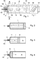
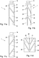
- a first embodiment of a dispensing device according to the invention is shown in side view.
- Fig. 2 shows a fully filled container in the form of an ampoule in side view.
- Fig. 3 showed a partially empty container in side view.
- Fig. 4 shows a completely empty container in side view.
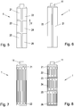
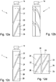
- Fig. 5 shows an alternative embodiment of a container with three pairs of measuring electrodes.
- Fig. 6 shows a second embodiment of the invention with a single pair of measuring electrodes.
- Fig. 7 shows a further embodiment of the invention with a pair of comb-shaped measuring electrodes.
- Fig. 8 shows a further embodiment of the invention with three comb-shaped pairs of measuring electrodes.
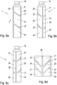
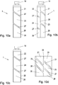
- Fig. 9a to 12d show further embodiments of containers with inclined electrodes.
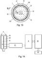
- Fig. 13 shows an embodiment of a device according to the invention in cross section.
- Fig. 13a shows a detail Fig. 1
- Fig. 14 and Fig. 15 show two means for determining the level within the container and for transmitting the determined level to an external data communication device.
- Fig. 16 shows a shield in the form of a film with conductors arranged thereon.
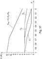
- Fig. 17 shows the theoretical course of the individual partial capacities during the emptying of the container at the in Fig. 15 illustrated embodiment.
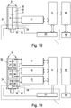
- the FIGS. 18 and 19 show the in the Fig. 14 and 15 illustrated embodiments, wherein additionally a touch detection is provided.
- Fig. 1 an embodiment of a dispensing device 100 according to the invention is shown in side view.
- the illustrated dispenser 100 includes a container 1 filled with a liquid medicament 12.
- a liquid medicament 12 In the present case 12 insulin is used as the liquid medicament, but it is also possible to fill other medicaments 12 in the container 1, such as hormone preparations (eg growth hormones, ...), biopharmaceuticals or medicines used in the course of therapeutic measures in reproductive medicine and subsequently administered in the same way.
- hormone preparations eg growth hormones, ...), biopharmaceuticals or medicines used in the course of therapeutic measures in reproductive medicine and subsequently administered in the same way.
- the dispenser 100 is in the form of a pen or ballpoint pen and can be conveniently held by a patient in the administration of the liquid 12 in the container 1.
- the container 1 is in the form of a cartridge or ampoule and is located in an end region 102 of the dispenser 100.
- the container 1 has a piston 13 which is mounted displaceably in the container 1.
- the container 1 has an internal volume which, apart from the region of the opening 11, has a constant cross section.
- the piston 13 closes the container 1 from the opposite side of the opening 11, so that the liquid contained in the container 1 12 is sealed in the container 1 and can escape exclusively through the opening 1.
- the inner region of the container 1 and the piston 13 have a circular cross-section and have a substantially cylindrical inner wall or outer wall.
- the liquid 12 located in the container 1 can escape through the opening 11 from the container 1.
- the liquid 12 is discharged through the opening 11 from the container 1.
- the opening 11 of the container 1 is before use, as in Fig. 2 represented by closed by a sealing member 14 so that the liquid 12 can not escape from the container 1.
- FIG. 3 shows the in Fig. 2 shown container 1 after a portion of the liquid 12 has been applied through the opening 11 via an injection needle 103.
- Fig. 4 shows the in Fig. 2 illustrated container 1 after the liquid 12 has been completely emptied from the container 1 through the opening 11 via an injection needle 103.
- the piston 13 in a middle position or in the end position, ie the container 1 is partially ( Fig. 3 ) or completely ( Fig. 4 ) emptied.
- the area 15 behind the piston 13 is air.
- the dispensing device 100 further has, in the region of the opening 11 of the container 1, an injection needle 103 which, on the one hand, penetrates the sealing element 14 and projects into the interior of the container 1 and, on the other hand, protrudes from the dispensing device 1.
- the injection needle 103 is connected in this embodiment with a housing 104 which is screwed onto the dispensing device 100.
- the dispensing device 100 has an external thread 105, which is adapted to a counter-shaped matching internal thread of the housing 104. If the piston 13, as in Fig. 3 shown displaced in the direction of the opening 11, the liquid contained in the interior of the container 1 through the opening 11 and the injection needle 103 can be administered to the respective patient.
- the housing of the dispensing device 100 has two viewing openings 108 in order to be able to visually determine the filling level F of the remaining liquid 12 present in the container 1.
- the dispenser 100 (FIG. Fig. 1 ) to an adjustment unit 106, with a certain feed of the piston 13 and - corresponding to it - a certain amount of the liquid to be dispensed 12 can be preset.
- a feed element 109 is pressed against the piston 13 of the container 1 by means of pressure actuation by the patient on an actuating unit 107.
- the piston 13 is pushed into the container 1 and the liquid 12 located in the container 1 is administered to the patient via the injection needle 103.
- the advancing element 109 is secured against resetting against the advancing direction V of the piston 13, ie away from the opening 11, so that the piston 13 can only be moved further in the direction of the opening 11.
- a container 1 with three pairs of measuring electrodes as in Fig. 5 shown.
- the container 1 has, as in Fig. 5 shown, three pairs of measuring electrodes 21-26. All measuring electrodes 21-26 are arranged in the outer region of the container 1, in the present case on the outer wall of the container 1.
- All measuring electrodes 21-26 are arranged in the outer region of the container 1, in the present case on the outer wall of the container 1.
- are two each Measuring electrodes 21-26 associated with each other are spaced from one another in the circumferential direction on the outer wall of the container 1.
- the individual pairs of mutually associated measuring electrodes 21-26 are spaced from one another in the feed direction V of the piston 13.
- the measuring electrodes 25, 26 of the third pair are furthest away from the opening 11 of the container 1.
- the measuring electrodes 21, 22 of the first pair are closest to the opening 11.
- the measuring electrodes 23, 24 of the second pair of electrodes are - seen in the feed direction V of the piston 13 - between the measuring electrodes 21, 22; 25, 26 of the first and third pairs.
- the measuring electrodes 21-26 lie in a region of the outer wall of the container 1 to this area. In the in Fig. 5 illustrated embodiment, the measuring electrodes 21-26 have a rectangular shape. If a plurality of pairs of electrodes is used, it may be advantageous if the extent of a pair of electrodes in the feed direction V of the piston 13 corresponds to the extent of the piston 13 in its feed direction V.
- measuring electrodes 21-26 may be used for the measuring electrodes 21-26.
- other electrode shapes such as circular or comb-like electrode shapes, may be used for the measuring electrodes 21-26.
- the use of several pairs of measuring electrodes 21-26 is fundamentally advantageous in the sense of an accurate measurement of the liquid content or liquid level in elongate containers 1, it is not necessary in the case of short or compact containers 1.
- a single pair of measuring electrodes 21, 22 is provided, which are elongated and extending over the entire feed area extending.
- the two measuring electrodes 21, 22 are circumferentially opposite each other at the same height with respect to the feed direction V of the piston 13.
- measuring electrodes 21-16 are formed as comb electrodes or interdigital electrodes.
- the measuring electrodes 21-26 are associated with each other in pairs and have a comb structure, wherein the teeth of mutually associated measuring electrodes 21, 22; 23, 24; 25, 26 interlock.
- comb electrodes can be used both for an arrangement with a ( Fig. 7 ) as well as with several pairs of measuring electrodes 21, 22; 23, 24; 25, 26 are used.
- Fig. 9a to 12d show four different embodiments with separation regions 27 between the measuring electrodes 21-26, which are at an angle to the feed direction V. Furthermore, in these embodiments, an axis-parallel separation region 28 is provided, each of which mutually associated pairs of measuring electrodes 21, 22; 23, 24; 25, 26 separates each other.
- the invention provides for a dispensing device, an electrical shield 3 for electric fields outside the Measuring electrodes 21-26 jacket-like to arrange the container 1.
- Fig. 13 is a section through the container 1, which illustrates the shield 3, the measuring electrodes 21, 22, the wall of the container and the liquid 12 in the interior of the container 1.
- the shielding 3 has the effect that the capacitance measured between the electrodes 21, 22 is not or only to a negligible extent falsified when a person touches or approaches the dispensing device 100 and thereby alters the electrical field conditions prevailing at the measuring electrodes 21, 22.
- the shield 3 is formed as a film of electrically conductive material, for example as a copper foil with a thickness of 50 microns, which is wrapped around the container 1 and the voltage applied to this measuring electrodes 21, 22.
- the measuring electrodes 21, 22 and the shield 3 are separated from each other and are not conductively connected to each other.
- the shield 3 serves to suppress the influence of external influences, for example changes in the permittivity and electric fields in the immediate outer region of the measuring electrodes 21, 22.
- the shield 3 surrounds both the measuring electrodes 21, 22 and the container 1 and is advantageously not located between the two Measuring electrodes and the container 1.
- Fig. 13a shows the detail Z Fig. 1 in the section BB of Fig. 13 , Clearly recognizable - albeit not true to scale - the arrangement of the wall of the container. 1 opposite the electrodes 21, 23, 25 and the shield 3.
- the individual conductors 32-34 on the film 3 are shown in section. Outside the shield 3, the housing of the dispenser 100 is located.
- the shield 3 immediately outside the outer wall of the dispensing device 100 and / or outside a carrier at least partially enclosing the container 1.
- Fig. 14 a measuring arrangement for determining the capacitance of a single pair of measuring electrodes 21, 22 is shown.
- Fig. 15 shows a measuring arrangement using multiple pairs of measuring electrodes 21-26.
- a computing unit 6 in the form of a microcontroller is provided, to which one or three capacitance measuring devices 41, 42, 43 are connected upstream.
- Each pair of measuring electrodes 21-26 is one of each of in Fig. 15 associated capacitance measuring devices 41, 42, 43 assigned.
- the measuring electrodes 21-26 are connected to the terminals of the capacitance measuring devices 41, 42, 43, respectively.
- the arithmetic unit 6 determines a value for the fill level F on the basis of a calibration procedure described later. The arithmetic unit 6 holds this value at its output. This value can in particular be transmitted on request via an antenna 62 connected downstream of the arithmetic unit 6 to an external data communication device (not shown).
- the number of used pairs of measuring electrodes 21-26 can be adapted to the requirements of the accuracy of the measurement.
- the computing unit 6 is followed by a communication controller 61 which is connected to an antenna 62, in the present case a coil antenna.
- the communication controller 61 allows the transmission of the determined level F to an external data communication device.
- the external data communication device via the antenna 62 electrical energy to the communication controller 61, the arithmetic unit 6, as well as to the capacity measuring devices 41-43 transmits, so that the entire in Fig. 14 respectively.
- Fig. 15 shown circuit requires no separate power supply.
- the concrete determination of the filling level F of the liquid 12 in the container 1 is illustrated in greater detail below on the basis of the determined capacitance measured values C 1 , C 2 , C 3 .
- Fig. 17 is in each case the dependence of the individual capacitance values C 1 , C 2 , C 3 on the level F at the in Fig. 5 illustrated embodiment of a container 1 according to the invention shown schematically.
- the liquid 12 is located between the measuring electrodes 21-26.
- the piston 13 first enters the intermediate region between the measuring electrodes 21, 22 of the first measuring electrode pair, so that due to the lower permittivity of the piston 13 relative to the liquid 12, a continuous decrease in the capacitance measured value C 1 of the first pair of measuring electrodes can be observed.
- the piston 13 has been pushed through the intermediate region between the measuring electrodes 21, 22 of the first measuring electrode pair, there is air 15 between the two measuring electrodes 21, 22 of the first pair of measuring electrodes. Due to the still lower permittivity of the air between the two measuring electrodes 21, 22 of the first one Measuring electrode pair decreases between the measuring electrodes 21, 22 measured capacitance measurement C 1 still further.
- a similar behavior is also to be noted for the capacitance measurements C 2 , C 3 between the measuring electrodes 23-26 of the second and third pair of measuring electrodes when the container 1 is emptied.
- the sum C sum of the individual capacitance measurement values C 1 , C 2 , C 3 can be used to determine the fill level F.
- the associated sum C sum of the individual capacitance measurement values C 1 , C 2 , C 3 can be determined in each case for a number of different fill levels, with each sum F being assigned a sum C sum .
- the individual data records thus created, each comprising a capacitance measurement value C sum and a fill level F, are stored in a calibration memory in the arithmetic unit 6.
- the practice shows, apparently due to complex capacitive coupling phenomena of the measuring electrodes 21-26 with each other also very different courses of the measured capacitances C 1 , C 2 , C 3 as a function of the level F, which clearly from the in Fig. 17 deviate from the theoretically expected progressions.
- the measurable waveforms are very well reproducible and show for each capacitance C 1 , C 2 , C 3 different slopes in different curve sections or level ranges, contrary to the theoretical expectations, the greatest steepness of the curve or the largest capacitance change is not necessarily between those measuring electrodes 21-26 occurs between which is just the liquid level.
- a weighted sum may alternatively be used to calculate the fill level to form a simple sum of the three single capacitance measurements, with each of the three summands in each curve section having its own weight separately as part of the calibration is determined.
- a calibration is performed in which the filled with the drug container 1 or a reference container of identical design is emptied. During emptying, in each case the fill level F and the individual capacities C 1 , C 2 , C 3 are determined. Individual capacity values C 1 , C 2 , C 3 are thus available for each of the filling levels F occupied during emptying. In the present embodiment, 30 equidistant fill levels F are taken during the emptying, wherein the initial state is denoted by 1 and the completely empty state by 0.
- the capacitance values C 1 , C 2 , C 3 are stored in each case in a reference vector V ref , which is assigned to the respective fill level F and the respective weights a, b, c. For each level F, a reference vector V ref is thus available.
- the weights are determined by optimization such that the weighted sum a. C 1 + b. C 2 + c. C 3 represents a linear approximation for the level F.
- the Euclidean distance is used as the distance measure. Subsequently, those reference vectors V ref are determined which each have the next smallest distance to the vector V mess .
- An interpolating function for example a linear interpolation function, is determined which, when applied to the reference vectors V ref determined by calibration, returns the fill level F assigned to each of them.
- the capacitance values C 1 , C 2 , C 3 are used in the interpolation function and one obtains an averaged fill level value.
- the antenna 62 can advantageously be arranged on the outside of the shield 3.
- the shield 3 has a film 31 made of an electrically and magnetically non-conductive material, such as plastic.
- conductors 32-34 are applied in the form of printed conductors. If the conductors 32-34 are formed on the film 31 such that there are no large-scale conductor loops in which eddy currents can form, the electromagnetic waves emitted by the external data communication device are not significantly affected by the shield 3 and can be received by the antenna 62 become. Furthermore, this also makes it possible to transmit energy in the form of electromagnetic waves to the antenna 62, which is sufficient to supply sufficient power to the antenna connected to the electrical components.
- a measured value for the filling level F is then invalidated or invalidated if the electric field in the outer region of the container 1, e.g. was falsified by touches or the proximity of electrically conductive body or body with high dielectric permittivity.
- the shield 3 has an electrically and magnetically non-conductive foil 31 on which a plurality of conductors 32, 33, 34 are formed by coating.
- the film 31 is in the present embodiment made of flexible plastic.
- the Printed conductors have a layer thickness of approximately 50 ⁇ m and a width of approximately 1000 ⁇ m.
- widths of the conductors 32-34 are between 100 ⁇ m and 3000 ⁇ m.
- the width of the conductors 32-34 may be limited to less than 3 mm.
- the third conductor 34 extends meandering between the two comb conductors 32, 33.
- the third conductor 34 extends meandering between the two comb conductors 32, 33.
- both the front and back of the film 31 may be printed with conductors 32-34.
- a plurality of meander-shaped conductors 34 can be arranged side by side between the comb conductors 32, 33 or a plurality of conductors 34 can be arranged spirally on the film 31.
- Two conductor tracks namely one of the two comb conductors 32 and the meandering conductor 34, are used as touch sensor 5.
- the second comb conductor 33 is set to a predetermined ground potential and serves as an electrical shield. If a person touches the shield 3 or if the person approaches the shield 3, the capacitance between the conductors 32, 34 of the touch sensor 5 changes due to the change in the permittivity of the environment. The change of this capacitance between the conductors 32, 34 can be changed by means of a further capacitance measuring device 44 are determined, the conductors 32, 34 of the shield 3 and the touch sensor 5 are connected to the measuring terminals of the further capacitance measuring device 44.
- This further capacitance measuring device 44 determines a further capacitance value C 'and conducts it as in Fig. 18 respectively. Fig. 19 shown, to the arithmetic unit 6 on. If the change in the ascertained further capacitance measurement value C 'exceeds a predefined threshold value T, it is assumed that the error due to the Capacitance readings C 1 , C 2 , C 3 determined level F is faulty due to the contact. The determined level F is invalidated.
- a shield 3 which also acts as a touch detection 5 and consists of the comb conductor 32 and the meandering conductor 34.
- electrical shielding 3 and touch detection 5 are two completely separate and different units, which are defined by the in Fig. 16 shown concrete arrangement particularly advantageous, namely in a plane printable, can be realized.
- This functional separation of electrical shielding 3 and touch detection 5 is of course readily possible.
- An alternative embodiment of the invention allows the replacement of the container 1 from the dispensing device 100.
- a carrier not shown, is arranged outside the container 1 between the container 1 and the shield 3.
- measuring electrodes 21-26 are arranged on this.
- the carrier abuts the container 1 and is advantageously formed by a part of the housing of the dispensing device 100.
- the measuring electrodes 21-26 are arranged on the voltage applied to the container 1 wall of the carrier.
- the housing of the dispenser 100 can be opened and the container 1 can be removed from the housing of the dispenser 100.
- the carrier forms part of the dispenser 100.
- the Karlunikaitonscontroller 61, the arithmetic unit 6, the capacitance measuring devices 41-44 and the antenna 62 may be disposed on the film 31.
Description
Die Erfindung betrifft eine Abgabevorrichtung zur Abgabe von Flüssigkeiten, insbesondere von flüssigen Medikamenten an Personen, gemäß dem Oberbegriff des Patentanspruches 1. Weiters betrifft die Erfindung ein Verfahren zur Bestimmung und Validierung des Füllstandes in einem Behälter gemäß dem Oberbegriff des Patentanspruches 17.The invention relates to a dispenser for dispensing liquids, in particular liquid medicaments to persons, according to the preamble of
Die Erfindung kann insbesondere im Gesundheitswesen, beispielsweise in der Medizintechnik, Pharma- und Biotechnologie, Medizin und Pflege, Studien, usw. zur Überwachung der Abgabe von Medikamenten an Patienten eingesetzt werden.The invention may be used in particular in health care, for example in medical technology, pharmaceutical and biotechnology, medicine and nursing, studies, etc. for monitoring the delivery of medicaments to patients.
Aus dem Stand der Technik, wie etwa
Die Erfindung löst diese Aufgabe bei einer Abgabevorrichtung der eingangs genannten Art mit dem kennzeichnenden Merkmal des Patentanspruches 1.The invention solves this problem in a dispensing device of the type mentioned with the characterizing feature of
Zudem löst die Erfindung die Aufgabe bei einem Verfahren der eingangs genannten Art mit dem Merkmal des Kennzeichens des Patentanspruches 17.In addition, the invention solves the problem in a method of the type mentioned above with the feature of the characterizing part of claim 17th
Erfindungsgemäß sind bei einer Abgabevorrichtung zur Abgabe von Flüssigkeiten, insbesondere von flüssigen Medikamenten an Personen, vorgesehen:
- ein mit der Flüssigkeit gefüllten Behälter, der an einem Ende eine Öffnung zur Abgabe der Flüssigkeit aufweist, sowie
- zumindest ein Paar von im Außenbereich, insbesondere an der Wand, des Behälters einander gegenüberliegend angeordneten kapazitiven Messelektroden zur Bestimmung der Permittivität des jeweiligen Mediums im Zwischenbereich zwischen den Messelektroden, umfassend eine die Messelektroden mantelförmig umgebende und um den Behälter angeordnete Abschirmung.
- a container filled with the liquid, which has an opening for dispensing the liquid at one end, as well as
- at least one pair of capacitive measuring electrodes disposed opposite one another in the outer region, in particular on the wall, of the container for determining the permittivity of the respective medium in the intermediate region between the measuring electrodes, comprising a shield surrounding the measuring electrodes and surrounding the container.
Störungen, die durch das Berühren des Behälters während des Messvorganges aufgrund kapazitiver Effekte verursacht werden, werden mit der Erfindung wirksam vermieden.Disturbances caused by touching the container during the measuring process due to capacitive effects are effectively avoided with the invention.
Insbesondere kann durch die erfindungsgemäße Maßnahme vermieden werden, dass eine Berührung der Messelektroden durch die Hände eines Menschen oder eine Verfälschung des Feldes im Bereich der Messelektroden durch die Hände eines Menschen zu Änderungen des Füllstandsmesswertes führen.In particular, it can be avoided by the inventive measure that touching the measuring electrodes by the hands of a human or a falsification of the field in the region of the measuring electrodes by the hands of a person lead to changes in the level measurement.
Die Abschirmung ist als mit Leiterbahnen aus elektrisch leitfähigem Material beschichtete Folie ausgebildet. In einer bevorzugten Ausführungsform ist diese Folie um den Behälter angeordnet oder gewickelt. Eine solche Abschirmung verhindert die Verfälschung von Messergebnissen besonders vorteilhaft.The shield is formed as coated with conductor tracks of electrically conductive material film. In a preferred embodiment, this film is arranged or wound around the container. Such a shield prevents the falsification of measurement results particularly advantageous.
Vorteilhafterweise ist der Bereich zwischen der Flüssigkeit und den Messelektroden frei von der Abschirmung.Advantageously, the area between the liquid and the measuring electrodes is free of the shield.
Um eine Verschlechterung der Messergebnisse durch Einflüsse der Abschirmung zu vermeiden, kann vorgesehen sein, dass die Abschirmung von den Messelektroden in radialer Richtung beabstandet ist.In order to avoid a deterioration of the measurement results due to the effects of the shield, it can be provided that the shield is spaced from the measuring electrodes in the radial direction.
Um eine verbesserte Abschirmung zu erreichen und gleichzeitig eine Befestigung eines Halbleiterchips und einer Antenne im Bereich der Abschirmung oder auf der Folie zu ermöglichen, kann vorgesehen sein, dass die Abschirmung als mit Leitern in Form von Leiterbahnen beschichtete, insbesondere um den Behälter gewickelte, Folie ausgebildet ist, wobei vorzugsweise auf der Folie eine Kapazitätsmesschaltung, eine Recheneinheit und ein Kommunikationscontroller, insbesondere in Form eines Halbleiterchips, sowie eine Antenne aufgebracht sind.In order to achieve an improved shielding and at the same time to enable an attachment of a semiconductor chip and an antenna in the region of the shield or on the foil, it can be provided that the shield is formed as foil coated with conductors in the form of strip conductors, in particular wound around the container is, wherein preferably on the film, a capacitance measuring circuit, a computing unit and a communication controller, in particular in the form of a semiconductor chip, and an antenna are applied.
Um eine die Funkkommunikation mit der Antenne beeinträchtigende Veränderung des von einem externen Datenkommunikationsgerätes erzeugten elektromagnetischen Feldes zu vermeiden und gleichzeitig eine gute elektrische Abschirmung der Messelektroden zu ermöglichen, kann vorgesehen sein, dass die Leiter schleifenfrei und/oder frei von geschlossenen Leiterschleifen ausgebildet sind.In order to avoid a modification of the electromagnetic field generated by an external data communication device which interferes with the radio communication and at the same time allows a good electrical shielding of the measuring electrodes, it can be provided that the conductors are loop-free and / or free of closed conductor loops.
Die Ausgestaltung der Abschirmung, die gleichzeitig zur Berührungsdetektion verwendet werden kann und zudem eine Funkkommunikation mit einer auf die Abschirmung aufgebrachten Antenne ermöglicht, sieht vor, dass auf der Folie drei separate Leiter ausgebildet sind, wobei der erste und der zweite Leiter als ineinandergreifende Kammleiter ausgebildet sind und der dritte Leiter mäanderförmig ausgebildet zwischen den beiden Kammleitern liegt.The design of the shield, which can be used simultaneously for the detection of touch and also allows wireless communication with an antenna applied to the shield, provides that three separate conductors are formed on the film, wherein the first and the second conductor are formed as intermeshing comb conductor and the third conductor is formed meander-shaped between the two comb conductors.
Eine bevorzugte Maßnahme zur Bestimmung des Füllstandes der Flüssigkeit im Inneren des Behälters sieht vor, dass die beiden gegenüberliegenden Messelektroden an eine Kapazitätsmesseinrichtung angeschlossen sind.A preferred measure for determining the level of the liquid inside the container provides that the two opposite measuring electrodes are connected to a capacitance measuring device.
Zur einfachen Ermittlung des Füllstandes kann vorgesehen sein, dass der von der Kapazitätsmesseinrichtung ermittelte Kapazitätswert einer Recheneinheit zugeführt ist, die aufgrund des ermittelten Kapazitätswerts mittels einer vorgegebenen abgespeicherten Kalibrierfunktion den Füllstand der Flüssigkeit im Behälter bestimmt und an ihrem Ausgang zur Verfügung hält.For a simple determination of the fill level it can be provided that the capacitance value ascertained by the capacitance measuring device is supplied to a computing unit which, on the basis of the ascertained capacitance value, determines the fill level of the liquid in the vessel by means of a predetermined stored calibration function and keeps it available at its output.
Eine besonders wirksame Abschirmung mit guter Abschirmungswirkung kann erzielt werden, indem einer der drei Leiter, insbesondere der als Kammleiter ausgebildete zweite Leiter, mit dem Massenanschluss der Kapazitätsmesseinrichtung verbunden ist.A particularly effective shielding with a good shielding effect can be achieved by one of the three conductors, in particular the second conductor designed as a comb conductor, being connected to the ground connection of the capacitance measuring device.
Um Berührungen oder Verfälschungen der Kapazitätsmessung vorteilhaft feststellen zu können, kann ein außerhalb oder im Bereich der Abschirmung angeordneter, insbesondere kapazitiver, Berührungssensor vorgesehen sein.In order to be able to determine advantageous contacts or falsifications of the capacitance measurement, a contact sensor arranged outside or in the region of the shield, in particular capacitive, can be provided.
Eine produktionstechnische einfach zu fertigende Variante sieht vor, dass der Berührungssensor den ersten Kammleiter und den mäanderförmigen Leiter der Abschirmung als Sensorelektroden umfasst.A production-related easy-to-manufacture variant provides that the touch sensor comprises the first comb conductor and the meandering conductor of the shield as sensor electrodes.
Hierbei kann zur Detektion von Berührungen vorgesehen sein, dass die Sensorelektroden des Berührungssensors an eine weitere Kapazitätsmesseinrichtung angeschlossen sind, und dass vorzugsweise der von der weiteren Kapazitätsmesseinrichtung ermittelte weitere Kapazitätswert der Recheneinheit zugeführt ist, und die Recheneinheit für den Fall, dass der ermittelte weitere Kapazitätswert einen vorgegebenen Schwellenwert übersteigt, die Weiterleitung des von ihr ermittelten Füllstands unterdrückt oder als ungültig kennzeichnet.In this case, it may be provided for the detection of touches that the sensor electrodes of the touch sensor are connected to a further capacitance measuring device, and that preferably the further capacitance value determined by the further capacitance measuring device is supplied to the arithmetic unit, and the arithmetic unit for the case that the determined further capacitance value exceeds specified threshold, suppressed the forwarding of the level determined by it or marked as invalid.
Ein vorteilhafter Behälter zur Aufnahme von Flüssigkeiten, der einfach entleert werden kann und dessen Füllstand einfach festgestellt werden kann, sieht vor, dass der Behälter ein Innenvolumen aufweist, das abgesehen vom Bereich der Öffnung einen konstanten Innenquerschnitt aufweist,
wobei ein den Behälter und die darin befindliche Flüssigkeit abschließender und abdichtender Kolben vorgesehen ist, dessen Außenquerschnitt dem Querschnitt des Innenvolumens des Behälters entspricht und der im Inneren des Behälters verschiebbar angeordnet ist, sodass bei Vorschub des Kolbens zur Öffnung hin die Flüssigkeit durch die Öffnung aus dem Behälter abgegeben wird.An advantageous container for holding liquids, which can be easily emptied and whose level can be easily determined, provides that the container has an internal volume which, apart from the region of the opening, has a constant internal cross-section,
wherein a the container and the liquid contained therein sealing and sealing piston is provided, the outer cross section of the cross section of Inner volume of the container corresponds and which is arranged displaceably in the interior of the container, so that upon advancement of the piston towards the opening, the liquid is discharged through the opening from the container.
Zur genaueren Bestimmung des Füllstandes kann vorgesehen sein, dass am Behälter eine Vielzahl von Paaren von zusätzlichen Messelektroden angeordnet sind, wobei insbesondere für jedes Paar von zusätzlichen Messelektroden jeweils eine zusätzliche dem Paar von zusätzlichen Messelektroden nachgeschaltete Kapazitätsmesseinrichtung vorgesehen ist, die den ermittelten Kapazitätswert an die Recheneinheit abgibt.For a more accurate determination of the fill level it can be provided that a plurality of pairs of additional measuring electrodes are arranged on the container, wherein in each case an additional pair of additional measuring electrodes downstream of the capacitance measuring device is provided for each pair of additional measuring electrodes, the calculated capacitance value to the computing unit emits.
Eine vorteilhafte Elektrodenanordnung, die eine genaue Füllstandsbestimmung ermöglicht, sieht vor, dass die jeweils einander paarweise zugeordneten Messelektroden einander in Umfangsrichtung des Behälters, insbesondere diametral, gegenüberliegen und insbesondere in Richtung des Vorschubs des Kolbens auf derselben Höhe liegen.An advantageous electrode arrangement, which allows an accurate filling level determination, provides that the respective pairwise associated measuring electrodes face each other in the circumferential direction of the container, in particular diametrically, and in particular in the direction of advancement of the piston at the same height.
Hierbei kann zusätzlich zur Verbesserung der Detektionsgenauigkeit vorgesehen sein, dass jeweils benachbarte Paare von Messelektroden in Richtung des Vorschubs des Kolbens beabstandet angeordnet sind und/oder
dass die Breite der Messelektroden in Richtung des Vorschubs des Kolbens der Breite des Kolbens in dessen Vorschubrichtung entspricht.In this case, in addition to improving the detection accuracy, it may be provided that respectively adjacent pairs of measuring electrodes are arranged at a distance in the direction of the advance of the piston and / or
in that the width of the measuring electrodes in the direction of the advance of the piston corresponds to the width of the piston in its direction of advance.
Bevorzugte Ausführungen der Messelektroden mit einem einfachen Aufbau sehen vor,
- dass die Messelektroden flächenhaft auf der Außenoberfläche des Behälters angeordnet sind und insbesondere die Form eines Rechtecks, eines Dreiecks, eines Trapezes oder eines Parallelogramms aufweisen, und/oder
- dass je zwei der einander paarweise zugeordneten Messelektroden durch zwei ineinandergreifende Kammleiter ausgebildet sind, die im Außenbereich, insbesondere an der Außenwand, des Behälters angeordnet sind.
- that the measuring electrodes are arranged in a planar manner on the outer surface of the container and in particular have the shape of a rectangle, a triangle, a trapezoid or a parallelogram, and / or
- in that each two of the measuring electrodes assigned to each other in pairs are formed by two intermeshing comb conductors which are arranged in the outer region, in particular on the outer wall, of the container.
Um einen einfachen Austausch der Behälter zu ermöglichen, kann vorgesehen sein, dass außerhalb des Behälters zwischen dem Behälter und der Abschirmung ein Träger angeordnet ist, auf dem die Messelektroden angeordnet sind, wobei der Träger vorzugsweise am Behälter anliegt und/oder dass die Messelektroden auf der am Behälter anliegenden Wand des Trägers angeordnet sind.In order to allow easy replacement of the container, it can be provided that a carrier is arranged outside the container between the container and the shield, on which the measuring electrodes are arranged, wherein the carrier preferably bears against the container and / or that the measuring electrodes on the arranged on the container wall of the carrier are arranged.
Vorteilhafterweise kann der ermittelte Füllstand an ein externes Kommunikationsgerät übermittelt werden. Hierbei kann vorgesehen sein, dass an die Recheneinheit ein Kommunikationscontroller mit einer ihm nachgeschalteten Antenne angeschlossen ist. Vorteilhafterweise kann für eine platzsparendere Anordnung vorgesehen sein, dass die Antenne im Au ßenbereich der Abschirmung oder unmittelbar auf der Abschirmung, jedoch nicht elektrisch leitfähig mit dieser verbunden, angeordnet ist.Advantageously, the determined level can be transmitted to an external communication device. It can be provided that to the arithmetic unit Communication controller is connected to a downstream antenna. Advantageously, it can be provided for a more space-saving arrangement that the antenna is arranged in the outer region of the shield or directly on the shield, but not electrically conductively connected thereto.
Weiters betrifft die Erfindung ein Verfahren zur Bestimmung und Validierung des Füllstandes in einem Behälter, der insbesondere in einer erfindungsgemäßen Abgabevorrichtung angeordnet ist, wobei zumindest ein Paar von im Außenbereich des Behälters einander gegenüberliegend angeordneten, insbesondere mit einer äußeren Abschirmung versehenen, Messelektroden zur Kapazitätsmessung vorgesehen ist, wobei die Kapazität zwischen den beiden Messelektroden ermittelt wird und aufgrund der ermittelten Kapazität gemäß einer vorgegebenen Kalibrierfunktion ein Füllstandswert bestimmt wird,
Erfindungsgemäß ist bei einem solchen Verfahren vorgesehen,
- dass eine weitere Kapazität mit im Außenbereich der Messelektroden im Bereich der Abschirmung, insbesondere auf der Abschirmung, angeordneten Leitern ermittelt wird,
- dass die weitere Kapazität mit einem Schwellenwert verglichen wird, und
- dass der Füllstandswert nur dann als gültig angesehen wird, wenn die weitere Kapazität unterhalb des Schwellenwerts liegt.
According to the invention, it is provided in such a method,
- that a further capacitance is determined with conductors arranged in the outer region of the measuring electrodes in the region of the shield, in particular on the shield,
- that the additional capacity is compared with a threshold, and
- the level value is considered valid only if the additional capacity is below the threshold value.
Mit einem solchen Verfahren kann einfach überprüft werden, ob der ermittelte Füllstandswert dadurch verfälscht wurde, dass eine Person die Messelektroden oder die Abschirmung im Bereich der Messelektroden berührt hat oder den Messelektroden hinreichend nahe gekommen ist, um eine Verfälschung zu verursachen.Such a method makes it easy to check whether the level determined has been falsified by the fact that a person has touched the measuring electrodes or the shield in the region of the measuring electrodes or has come sufficiently close to the measuring electrodes in order to cause falsification.
Zur genauen Bestimmung des Füllstandes kann vorgesehen sein, dass der Füllstandwert und/oder eine Aussage über die Gültigkeit des Füllstandswertes durch codierte elektromagnetischer Datenübertragung, insbesondere durch Lastmodulation, an ein externes Datenkommunikationsgerät übertragen wird.For accurate determination of the fill level, it may be provided that the fill level value and / or a statement about the validity of the fill level value is transmitted by coded electromagnetic data transmission, in particular by load modulation, to an external data communication device.
Zum selben Zweck kann vorgesehen sein, dass jeweils die Kapazitäten einer Vielzahl von, insbesondere drei, Paaren von Messelektroden, die einander im Außenbereich des Behälters gegenüberliegen, ermittelt werden und der Füllstandswert aufgrund der Kapazitäten ermittelt wird.For the same purpose it can be provided that in each case the capacitances of a plurality of, in particular three, pairs of measuring electrodes, which are opposite one another in the outer region of the container, are determined and the fill level value is determined on the basis of the capacitances.
Eine besonders genaue Detektion wird ermöglicht, indem
- a) für eine Anzahl von Füllständen jeweils Referenzvektoren umfassend die Kapazitäten zwischen den einzelnen Paaren von Messelektroden als Komponenten zur Verfügung gestellt werden, und
- b) jedem dieser Vektoren der jeweilige Füllstand zugeordnet wird,
- c) ein Vektor umfassend die einzelnen ermittelten Kapazitäten ermittelt wird,
- d) eine Anzahl von Referenzvektoren gesucht wird, die vom Vektor den geringsten, insbesondere euklidischen, Abstand aufweisen,
- e) eine Interpolationsfunktion gebildet wird, die bei Anwendung auf die in Schritt b) aufgefundenen Referenzvektoren den jeweiligen, diesen Referenzvektoren zugeordneten Füllstand ergibt,
- f) die Interpolationsfunktion auf den Vektor angewendet wird und das Ergebnis als Füllstand herangezogen wird.
- a) for a number of filling levels, reference vectors each comprising the capacitances between the individual pairs of measuring electrodes are provided as components, and
- b) each level is assigned to each of these vectors,
- c) a vector is determined comprising the individual determined capacities,
- d) a number of reference vectors is searched for which have the least, in particular Euclidean, distance from the vector,
- e) an interpolation function is formed, which, when applied to the reference vectors found in step b), results in the respective fill level associated with these reference vectors,
- f) the interpolation function is applied to the vector and the result is used as a level.
Mehrere bevorzugte Ausführungsformen der Erfindung werden anhand der folgenden Zeichnungsfiguren näher erläutert.Several preferred embodiments of the invention will be explained in more detail with reference to the following drawing figures.
In
Die
In
Die Abgabevorrichtung 100 weist die Form eines Schreibstifts oder Kugelschreibers auf und kann von einem Patienten bei der Verabreichung der im Behälter 1 befindlichen Flüssigkeit 12 bequem in der Hand gehalten werden. Der Behälter 1 hat die Form einer Patrone oder Ampulle und befindet sich in einem Endbereich 102 der Abgabevorrichtung 100.The
Der Behälter 1, der im Detail in
In den Darstellungen der
In the representations of the
Wie in
Darüber hinaus weist die Abgabevorrichtung 100 (
Besonders vorteilhaft ist die Verwendung eines Behälters 1 mit drei Paaren von Messelektroden, wie in
Alternativ können jedoch auch andere Elektrodenformen, etwa kreisförmige oder kammartige Elektrodenformen für die Messelektroden 21-26 verwendet werden. Die Verwendung mehrerer Paare von Messelektroden 21-26 ist im Sinne einer genauen Messung des Flüssigkeitsinhalts oder Flüssigkeitsstands in länglichen Behältern 1 zwar grundsätzlich vorteilhaft, aber gerade bei kurzen oder kompakten Behältern 1 nicht erforderlich. In einem in
Darüber hinaus ist es auch möglich, unterschiedliche Formen von Messelektroden 21-16 zu verwenden. Eine vorteilhafte Ausführungsform sieht vor, dass die Messelektroden 21-26 als Kammelektroden oder interdigitale Elektroden ausgebildet sind. Die Messelektroden 21-26 sind einander paarweise zugeordnet und weisen eine Kammstruktur auf, wobei die Zähne einander zugeordneter Messelektroden 21, 22; 23, 24; 25, 26 ineinander greifen. Wie in
Je nach Anwendungsfall ist es auch möglich, unterschiedlich große Messelektroden 21-26 vorzusehen, um eine besonders vorteilhafte Bestimmung des Füllstandes F im Behälter 1 zu ermöglichen. Besonders vorteilhaft ist die Verwendung von parallelogrammförmigen bzw. dreieckigen Messelektroden 21-26, bei denen die Elektroden durch Trennbereiche 27 voneinander getrennt sind, die zur Vorschubrichtung V des Kolbens bzw. der Längsachse des Behälters 1 im Winkel verlaufen, beispielsweise in einem Winkel von 45°. Bei einer solchen Anordnung ergibt sich ein fließender Übergang, sodass eine besonders genaue Bestimmung des Füllstandes F möglich wird. Die
Mit allen solchen Elektrodenanordnungen ist es möglich, aufgrund der Kapazität zwischen den Messelektroden 21-26 auf den Füllstand F des Behälters 1 zu schließen. Um eine möglichst präzise Messung der einzelnen Kapazitäten C1, C2, C3 zu ermöglichen und damit einen Rückschluss auf den Füllstand F des Behälters 1 ziehen zu können, sieht die Erfindung bei einer Abgabevorrichtung vor, eine elektrische Abschirmung 3 für elektrische Felder außerhalb der Messelektroden 21-26 mantelförmig um den Behälter 1 anzuordnen. In
Alternativ ist es auch möglich, die Abschirmung 3 unmittelbar außerhalb der Außenwand der Abgabevorrichtung 100 und/oder außerhalb eines den Behälter 1 zumindest teilweise umschließenden Trägers anzuordnen.
Alternatively, it is also possible to arrange the
Zur Bestimmung des momentanen Füllstandes F der Flüssigkeit 12 in Behälter 1 wird zunächst die vorhandene Kapazität zwischen den Messelektroden 21, 22 bestimmt. In
Selbstverständlich kann die Zahl der verwendeten Paare von Messelektroden 21-26 an die Anforderungen an die Genauigkeit der Messung angepasst werden. Insbesondere ist es auch möglich, ein einziges Paar von Messelektroden 21, 22 zu verwenden und nur den zwischen diesen Messelektroden 21, 22 ermittelten Kapazitätsmesswert C1 zur Bestimmung des Füllstands F heranzuziehen. (
Der Recheneinheit 6 ist ein Kommunikationscontroller 61 nachgeschaltet, der an eine Antenne 62, im vorliegenden Fall eine Spulenantenne, angeschlossen ist. Der Kommunikationscontroller 61 ermöglicht die Übertragung des ermittelten Füllstandes F an ein externes Datenkommunikationsgerät. Darüber hinaus kann auch noch vorgesehen sein, dass das externe Datenkommunikationsgerät über die Antenne 62 elektrische Energie an den Kommunikationscontroller 61, die Recheneinheit 6, sowie an die Kapazitätsmesseinrichtungen 41-43 überträgt, sodass die gesamte in
Im Folgenden wird die konkrete Ermittlung des Füllstandes F der Flüssigkeit 12 im Behälter 1 anhand der ermittelten Kapazitätsmesswerte C1, C2, C3 näher dargestellt. In
In einer besonderen Ausführungsform der Erfindung kann die Summe Csum der einzelnen Kapazitätsmesswerte C1, C2, C3 zur Bestimmung des Füllstands F herangezogen werden. Durch Ermittlung einer Kalibrierkurve kann für eine Anzahl von verschiedenen Füllständen jeweils die zugehörige Summe Csum der einzelnen Kapazitätsmesswerte C1, C2, C3 ermittelt werden, wobei jedem Füllstand F jeweils eine Summe Csum zugeordnet wird. Die so erstellten einzelnen Datensätze umfassend jeweils einen Kapazitätsmesswert Csum und einen Füllstand F werden in einem Kalibrierspeicher in der Recheneinheit 6 abgelegt.In a particular embodiment of the invention, the sum C sum of the individual capacitance measurement values C 1 , C 2 , C 3 can be used to determine the fill level F. By determining a calibration curve, the associated sum C sum of the individual capacitance measurement values C 1 , C 2 , C 3 can be determined in each case for a number of different fill levels, with each sum F being assigned a sum C sum . The individual data records thus created, each comprising a capacitance measurement value C sum and a fill level F, are stored in a calibration memory in the
Nach der Messung und Bestimmung der einzelnen Kapazitätsmesswerte C1, C2, C3 wird deren Summe Csum ermittelt und mit den einzelnen im Kalibrierspeicher abgespeicherten Summen Csum verglichen. Es wird dasjenige Paar ausgewählt, dessen zugehörige Summe Csum mit der Summe der ermittelten Kapazitätsmesswerte C1, C2, C3 am besten übereinstimmt. Der der am besten übereinstimmenden Summe Csum jeweils zugeordnete Füllstand wird als Füllstand F des Behälters 1 angesehen, die Recheneinheit 6 hält diesen Füllstand F an ihrem Ausgang zur Verfügung und gibt den Füllstand F, wie vorstehend beschrieben, auf Anfrage über eine Antenne 62 an ein externes Datenkommunikationsgerät ab.After the measurement and determination of the individual capacitance measurement values C 1 , C 2 , C 3 , their sum C sum is determined and compared with the individual sums C sum stored in the calibration memory. The pair whose sum C sum best matches the sum of the ascertained capacitance measurement values C 1 , C 2 , C 3 is selected. The one of the best matching sum C sum associated with each Level is regarded as a level F of the
Die Praxis zeigt, offenbar aufgrund komplexer kapazitiver Verkopplungsphänomene der Messelektroden 21-26 untereinander auch stark abweichende Verläufe der gemessenen Kapazitäten C1, C2, C3 in Abhängigkeit vom Füllstand F, die deutlich von den in
Um eine Umrechnung zwischen einzelnen Kapazitäten C1, C2, C3 und einem Füllstand F zu erreichen, wird eine Kalibrierung vorgenommen, bei der der mit dem Medikament gefüllte Behälter 1 oder ein baugleicher Referenzbehälter entleert wird. Während der Entleerung werden jeweils der Füllstand F sowie die einzelnen Kapazitäten C1, C2, C3 ermittelt. Für jeden der bei der Entleerung eingenommenen Füllstände F stehen somit jeweils einzelne Kapazitätswerte C1, C2, C3 zur Verfügung. Im vorliegenden Ausführungsbeispiel werden 30 äquidistande Füllstände F bei der Entleerung eingenommen, wobei der Ausgangszustand mit 1 und der vollständig entleerte Zustand mit 0 bezeichnet wird. Die Kapazitätswerte C1, C2, C3 werden jeweils in einem Referenzvektor Vref abgespeichert, der dem jeweiligen Füllstand F sowie den jeweiligen Gewichten a, b, c zugeordnet wird. Für jeden Füllstand F steht somit ein Referenzvektor Vref zur Verfügung. Die Gewichte werden durch Optimierung derart festgelegt, dass die gewichtete Summe a . C1 + b . C2 + c . C3 eine lineare Annäherung für den Füllstand F darstellt.In order to achieve a conversion between individual capacities C 1 , C 2 , C 3 and a level F, a calibration is performed in which the filled with the
Will man nun den tatsächlichen Füllstand F anhand von durch Messung ermittelten Kapazitätswerten C1, C2, C3 bestimmen, so kann dies aufgrund der während der Kalibrierung ermittelten Gewichte vorgenommen werden, wobei für jede Messung jeweils so viele Gewichte zur Verfügung stehen, wie Kapazitätswerte C1, C2, C3 ermittelt wurden. Zunächst wird aufgrund der ermittelten bzw. gemessenen Kapazitätswerte C1, C2, C3 ein Vektor Vmess [C1, C2, C3] erstellt, der die Kapazitätswerte C1, C2, C3 als Komponenten aufweist. Anschließend wird der Vektor Vmess mit den ermittelten Referenzvektoren Vref verglichen und derjenige Referenzvektor gesucht, der zum Vektor Vmess den geringsten Abstand aufweist. Im vorliegenden Ausführungsbeispiel wird als Abstandsmaß der Euklidische Abstand verwendet. Anschließend werden diejenigen Referenzvektoren Vref ermittelt, der den jeweils nächstkleinsten Abstand zum Vektor Vmess aufweisen. Es wird eine interpolierende Funktion, beispielsweise eine lineare Interpolationsfunktion bestimmt, die bei Anwendung auf die durch Kalibrierung ermittelten Referenzvektoren Vref den jeweils diesen zugeordneten Füllstand F zurückliefert. Die Kapazitätswerte C1, C2, C3 werden in die Interpolationsfunktion eingesetzt und man erhält einen gemittelten Füllstandswert.If one now wants to determine the actual fill level F on the basis of capacitance values C 1 , C 2 , C 3 determined by measurement, this may be due to the fact that during the Calibration determined weights are made, with each measurement as many weights are available as capacity values C 1 , C 2 , C 3 were determined. First, on the basis of the ascertained or measured capacitance values C 1 , C 2 , C 3, a vector V mess [C 1 , C 2 , C 3 ] is created which has the capacitance values C 1 , C 2 , C 3 as components. Subsequently, the vector V mess is compared with the determined reference vectors V ref , and the one reference vector is sought which has the smallest distance to the vector V mess . In the present embodiment, the Euclidean distance is used as the distance measure. Subsequently, those reference vectors V ref are determined which each have the next smallest distance to the vector V mess . An interpolating function, for example a linear interpolation function, is determined which, when applied to the reference vectors V ref determined by calibration, returns the fill level F assigned to each of them. The capacitance values C 1 , C 2 , C 3 are used in the interpolation function and one obtains an averaged fill level value.
Die Antenne 62 kann aus Platzgründen vorteilhafterweise außen auf der Abschirmung 3 angeordnet sein. Um eine vorteilhafte Kombination zu gewährleisten, weist die Abschirmung 3 eine Folie 31 aus einem elektrisch und magnetisch nicht leitfähigen Material, wie z.B. Kunststoff auf. Auf der Folie 31, dargestellt in
Sofern eine zusätzliche Genauigkeit bei der Bestimmung des Füllstandes F im Inneren des Behälters 1 erforderlich ist, kann vorgesehen sein, dass ein Messwert für den Füllstand F dann invalidiert bzw. für ungültig erklärt wird, wenn das elektrische Feld im Außenbereich des Behälters 1, z.B. durch Berührungen bzw. das Nahekommen elektrisch leitfähiger Körper oder Körper mit hoher dielektrischer Permittivität verfälscht wurde.If additional accuracy is required in the determination of the filling level F inside the
Die Abschirmung 3 weist eine elektrisch und magnetisch nicht leitfähige Folie 31 auf, auf der eine Vielzahl von Leitern 32, 33, 34 durch Beschichtung ausgebildet sind. Die Folie 31 besteht im vorliegenden Ausführungsbeispiel aus biegsamem Kunststoff. Die Leiterbahnen weisen eine Schichtdicke von ca. 50 µm und eine Breite von etwa 1000 µm auf. Vorteilhaft sind Breiten der Leiter 32-34 zwischen 100 µm und 3000 µm.The
Um die Ausbildung von Wirbelströmen und dadurch eine Beeinträchtigungen einer NFC-Kommunikation zu vermeiden, kann die Breite der Leiter 32-34 auf weniger als 3 mm beschränkt werden. Darüber hinaus können die Leiter 32-34, wie in
In diesem besonderen Ausführungsbeispiel der Erfindung sind deshalb zwei der drei Leiter 32, 33 als ineinandergreifende Kammleiter 32, 33 ausgebildet, der dritte Leiter 34 verläuft mäanderförmig zwischen den beiden Kammleitern 32, 33. Neben diesem Ausführungsbeispiel gibt es selbstverständlich auch noch eine Vielzahl weiterer Ausführungsbeispiele der schleifenfreien Anordnung mehrerer miteinander nicht elektrisch verbundenen Leiterbahnen bzw. Elektroden auf der Oberfläche einer Folie 31 oder im Inneren bzw. zwischen einzelnen Lagen einer mehrlagig aufgebauten Folie. Auch können sowohl Vorderseite als auch Rückseite der Folie 31 mit Leitern 32-34 bedruckt sein. Alternativ können auch mehrere mäanderförmige Leiter 34 nebeneinander zwischen den Kammleitern 32, 33 angeordnet werden oder mehrere Leiter 34 spiralenförmig auf der Folie 31 angeordnet sein.In this particular embodiment of the invention, therefore, two of the three
Zwei Leiterbahnen, nämlich einer der beiden Kammleiter 32 sowie der mäanderförmige Leiter 34, werden als Berührungssensor 5 verwendet. Der zweite Kammleiter 33 wird auf ein vorgegebenes Massepotential gelegt und dient als elektrische Abschirmung. Berührt eine Person die Abschirmung 3 oder kommt die Person der Abschirmung 3 nahe, so verändert sich aufgrund der Änderung der Permittivität der Umgebung die Kapazität zwischen den Leitern 32, 34 des Berührungssensors 5. Die Veränderung dieser Kapazität zwischen den Leitern 32, 34 kann mittels einer weiteren Kapazitätsmesseinrichtung 44 bestimmt werden, die Leiter 32, 34 der Abschirmung 3 bzw. des Berührungssensors 5 sind an die Messanschlüsse der weiteren Kapazitätsmesseinrichtung 44 angeschlossen. Diese weitere Kapazitätsmesseinrichtung 44 bestimmt einen weiteren Kapazitätswert C' und leitet diesen, wie in
Im vorliegenden besonderen Ausführungsbeispiel der Erfindung wird eine Abschirmung 3 verwendet, die zugleich als Berührungsdetektion 5 fungiert und aus dem Kammleiter 32 und dem mäanderförmig verlaufenden Leiter 34 besteht. Aus physikalischer bzw. funktioneller Sicht sind elektrische Schirmung 3 und Berührungsdetektion 5 jedoch zwei völlig getrennte und unterschiedliche Einheiten, die sich durch die in
Eine alternative Ausführungsform der Erfindung ermöglicht das Austauschen des Behälters 1 aus der Abgabevorrichtung 100. Außerhalb des Behälters 1 zwischen dem Behälter 1 und der Abschirmung 3 ist ein nicht dargestellter Träger angeordnet. Auf diesem befinden sich Messelektroden 21-26. Der Träger liegt am Behälter 1 an und ist vorteilhafterweise durch einen Teil des Gehäuses der Abgabevorrichtung 100 ausgebildet. Die Messelektroden 21-26 sind auf der am Behälter 1 anliegenden Wand des Trägers angeordnet. Das Gehäuse der Abgabevorrichtung 100 lässt sich öffnen und der Behälter 1 kann aus dem Gehäuse der Abgabevorrichtung 100 entfernt werden. Der Träger bildet einen Teil der Abgabevorrichtung 100.An alternative embodiment of the invention allows the replacement of the
Vorteilhafterweise können der Kommunikaitonscontroller 61, die Recheneinheit 6, die Kapazitätsmesseinrichtungen 41-44 sowie die Antenne 62 auf der Folie 31 angeordnet sein.Advantageously, the
Claims (20)
- An administration device for administering liquids (12), in particular liquid drugs, to persons, the device comprising:- a container (1) filled with the liquid (12) and having an opening (11) formed therein on one end to administer the liquid (12),- at least one pair of capacitive measurement electrodes (21, 22) disposed in the outer area, in particular on the wall, of the container (1) opposite one another, to determine the permittivity of the medium in the space between the measurement electrodes; and- a cover (3) surrounding the measurement electrodes (21, 22) in a jacket-like manner and disposed around the container (1),wherein the cover (3) has a film (31) coated with conductors (32, 33, 34) in a form of conductive tracks,
characterised in that
three separate conductors (32, 33, 34) are formed on the film (31), wherein the first and second conductors (32, 33) are formed as mutually engaging comb conductors, and the third conductor (34) is formed in a meander-shaped manner between the two comb conductors (32, 33). - The administration device according to claim 1, characterised
in that the area between the liquid (12) and the measurement electrodes (21, 22) is free of the cover (3), and/or
in that the cover (3) is spaced apart from the measurement electrodes (21, 22), and/or in that the film of the cover (3) is wound or arranged around the container (1). - The administration device according to claim 1 or 2, characterised in that the conductors (32, 33, 34) are formed in a loop-free manner and/or free of closed conductor loops.
- The administration device according to any one of the preceding claims and/or in that the conductors (32, 33, 34) have a thickness of at most 3 mm, in particular of between 50 µm and 150 µm.
- The administration device according to any one of the preceding claims, characterised in that
a communications controller (61) and/or a number of capacitance measuring devices for establishing the capacitance between the measurement electrodes (21, 22) and/or a processing unit (6) and/or an antenna (62) for transmitting measurement values established by the measurement electrodes (21, 22) or values derived therefrom, in particular fill level values (F), are arranged on the film (31), and in that these units arranged on the film (31) are preferably integrated in a common housing of a semiconductor chip. - The administration device according to any one of the preceding claims, characterised in that the two measurement electrodes (21, 22) disposed opposite one another are connected to a capacitance measuring device (41), and in that the capacitance value (C1) established by the capacitance measuring device (41) is preferably supplied to a processing unit (6), which, based on the established capacitance value (C1), determines the fill level (F) of the liquid (12) in the container (1) by means of a specified stored calibration function and makes the determined fill level available at an output.
- The administration device according to claim 6, characterised in that one of the three conductors (32, 33, 34), in particular the second conductor (33) formed as a comb conductor, is connected to the ground connection of the capacitance measuring device (41).
- The administration device according to any one of the preceding claims, characterised by a contact sensor (5), in particular a capacitive contact sensor, disposed outside or in the area of the cover (3), wherein the contact sensor (5) preferably comprises the first comb conductor (32) and the meander-shaped conductor (34) of the cover (3) as sensor electrodes.
- The administration device according to claim 8, characterised in that the sensor electrodes of the contact sensor (5) are connected to a further capacitance measuring device (44), and in that the further capacitance value (C') established by the further capacitance measuring device (44) is fed to the computing unit (6), and the computing unit (6) suppresses the forwarding of the fill level (F) established by the processing unit or marks the fill level invalid if the established further capacitance value (C') exceeds a specified threshold value (T).
- The administration device according to any one of the preceding claims, characterised in that the container (1) has an internal volume having a constant internal cross section with the exception of the area of the opening (11),
wherein a plunger (13) sealing the container (1) and the liquid (12) contained therein is provided, the outer cross section of the plunger corresponding to the cross section of the internal volume of the container (1), and the plunger being disposed movably inside the container (1), such that, when the plunger (13) is moved towards the opening (11), the liquid (12) is administered out of the container (1) through the opening (11). - The administration device according to any one of the preceding claims, characterised in that a plurality of pairs of additional measurement electrodes (23, 24; 25, 26) are disposed on the container (1), wherein additional capacitance measuring devices (42, 43) downstream of the pairs of additional measurement electrodes (23, 24; 25, 26) are provided, in particular one on each pair of additional measurement electrodes (23, 24; 25, 26), and output the established capacitance value (C2, C3) to the processing unit (6).
- The administration device according to any one of the preceding claims, characterised in that the measurement electrodes (21, 22; 23, 24; 25, 26) associated with one another in pairs are mutually opposed, in particular diametrically, in the peripheral direction of the container (1), and in particular are arranged at the same height in particular in the direction of movement of the plunger (13).
- The administration device according to claim 12, characterised in that adjacent pairs of measurement electrodes (21, 22; 23, 24; 25, 26) are disposed at a distance in a direction of movement of the plunger (13), and/or
in that the width of the measurement electrodes (21, 22; 23, 24; 25, 26) in the direction (V) of movement of the plunger (13) corresponds to the width of the plunger (13) in the direction of movement (V) thereof. - The administration device according to any one of the preceding claims, characterised- in that the measurement electrodes (21, 22; 23, 24; 25, 26) are arranged two-dimensionally on the outer surface of the container (1) and in particular have the shape of a rectangle, a triangle, a trapezium or a parallelogram, and/or- in that each two of the measurement electrodes (21, 22; 23, 24; 25, 26) associated with one another in pairs are formed by two mutually engaging comb conductors that are disposed in the outer area, in particular on the outer wall, of the container (1).
- The administration device according to any one of the preceding claims, characterised in that a support is disposed outside the container (1), between the container (1) and the cover (3), the measurement electrodes (21, 22; 23, 24; 25, 26) being disposed on the support, wherein the support preferably abuts the container (1), and/or in that the measurement electrodes (21, 22; 23, 24; 25, 26) are disposed on the wall of the support abutting the container (1), wherein in particular a part of the housing of the administration device (100) is formed as a support or the support is connected to the housing.
- The administration device according to any one of the preceding claims, characterised in that a communications controller (61) with a downstream antenna (62) is connected to the processing unit (6),
wherein in particular the antenna (62) is disposed in the outer area of the cover (3) or directly on the cover (3), but is not connected to the cover (3) in an electrically conductive manner. - A method for determining and validating the fill level (F) in a container (1) disposed in particular in an administration device (100) according to any one of the preceding claims, wherein at least one pair of measurement electrodes (21, 22) for measuring a capacitance, disposed opposite one another in the outer area of the container (1) and in particular provided with an outer cover (3), is provided, wherein the capacitance (C1) between the two measurement electrodes (21, 22) is established and a fill level value (F) is determined based on the established capacitance (C1) according to a specified calibration function,
characterised in that- a further capacitance (C') is established using conductors (33, 34) arranged in the outer area of the measurement electrodes (21, 22) in the area of the cover (3), in particular on the cover (3),- in that the further capacitance (C') is compared with a threshold value (T), and- in that the fill level (F) is only considered valid if the further capacitance (C') is below the threshold value (T). - The method according to claim 17, characterised in that the fill level value (F) and/or information regarding the validity of the fill level value (F) is transmitted to an external data communications device by encoded electromagnetic data transmission, in particular by load modulation.
- The method according to claim 17 or 18, characterised in that the capacitances (C1, C2, C3) of a plurality of pairs, in particular three pairs, of measurement electrodes (21-26), which are disposed opposite one another in the outer area of the container (1) are established, and the fill level value (F) is established on the basis of the capacitances.
- The method according to claim 19, characterised in thata) a reference vector (Vref) containing the capacitances (C1 C2, C3) between the individual pairs of measurement electrode (21-26) is made available as component for each of a number of fill levels (F), andb) a fill level (F) is associated with each of these vectors,c) a vector (Vmess) containing the individual established capacitances (C1, C2, C3) is established,d) a number of reference vectors (Vref) that are at the smallest, in particular Euclidean distance from the vector (Vmess) is sought,e) an interpolation function is formed that, when applied to the reference vectors (Vref) found in step b), provides the fill levels (F) associated with these reference vectors (Vref), andf) the interpolation function is applied to the vector (Vmess) and the result is used as the fill level.
Applications Claiming Priority (2)
| Application Number | Priority Date | Filing Date | Title |
|---|---|---|---|
| ATA50428/2012A AT513452B1 (en) | 2012-10-05 | 2012-10-05 | Dispensing device for medicaments |
| PCT/AT2013/050187 WO2014052997A1 (en) | 2012-10-05 | 2013-09-17 | Dispensing device for medications |
Publications (2)
| Publication Number | Publication Date |
|---|---|
| EP2903662A1 EP2903662A1 (en) | 2015-08-12 |
| EP2903662B1 true EP2903662B1 (en) | 2018-10-24 |
Family
ID=49474166
Family Applications (1)
| Application Number | Title | Priority Date | Filing Date |
|---|---|---|---|
| EP13780052.0A Not-in-force EP2903662B1 (en) | 2012-10-05 | 2013-09-17 | Administration device for drugs |
Country Status (11)
| Country | Link |
|---|---|
| US (1) | US9395716B2 (en) |
| EP (1) | EP2903662B1 (en) |
| JP (1) | JP6163209B2 (en) |
| CN (1) | CN104812424B (en) |
| AT (1) | AT513452B1 (en) |
| BR (1) | BR112015007285A2 (en) |
| DK (1) | DK2903662T3 (en) |
| ES (1) | ES2698124T3 (en) |
| IN (1) | IN2015DN02678A (en) |
| RU (1) | RU2661008C2 (en) |
| WO (1) | WO2014052997A1 (en) |
Families Citing this family (31)
| Publication number | Priority date | Publication date | Assignee | Title |
|---|---|---|---|---|
| AT512504B1 (en) * | 2012-03-22 | 2013-09-15 | Seibersdorf Labor Gmbh | Apparatus and method for determining the capacity |
| AT515762B1 (en) * | 2014-04-15 | 2016-02-15 | Seibersdorf Labor Gmbh | Dispensing device for dispensing liquids |
| EP2982400A1 (en) * | 2014-08-07 | 2016-02-10 | Valtronic Technologies (Holding) SA | Device for attachment to a portable liquid injection device |
| AT516283B1 (en) * | 2015-01-28 | 2016-04-15 | Seibersdorf Labor Gmbh | dispenser |
| US10953157B2 (en) * | 2015-04-16 | 2021-03-23 | Sanofi-Aventis Deutschland Gmbh | Sensor and sensor assembly for capacitive determination of a filling level |
| WO2017021227A1 (en) * | 2015-07-31 | 2017-02-09 | Sanofi-Aventis Deutschland Gmbh | Sensor, cartridge and drug delivery device |
| US11020529B2 (en) * | 2015-07-31 | 2021-06-01 | Sanofi-Aventis Deutschland Gmbh | Sensor for a drug delivery device |
| CN107847677B (en) * | 2015-07-31 | 2021-01-29 | 赛诺菲-安万特德国有限公司 | Sensor, cartridge and drug delivery device |
| WO2017021229A1 (en) * | 2015-07-31 | 2017-02-09 | Sanofi-Aventis Deutschland Gmbh | Sensor, cartridge and drug delivery device |
| US9638570B2 (en) * | 2015-08-07 | 2017-05-02 | Finetek Co., Ltd. | Calibration method for capacitance level sensing apparatus and anti-interference method for plural capacitance level sensing apparatuses |
| EP3352818B1 (en) * | 2015-09-23 | 2019-12-25 | Sanofi-Aventis Deutschland GmbH | A device for attachment to an injection device |
| DE102015013886A1 (en) * | 2015-10-28 | 2017-05-04 | Audi Ag | Level determination device, fluid container arrangement and method for operating a filling level determination device |
| KR101868841B1 (en) * | 2016-03-04 | 2018-06-20 | 주식회사 코아비스 | Fuel level detecting apparatus using electric capacity |
| AT518695B1 (en) * | 2016-05-20 | 2018-08-15 | Ait Austrian Inst Tech Gmbh | Arrangement for determining the level of the liquid in the carpule |
| TWI628419B (en) * | 2016-08-25 | 2018-07-01 | 聯陽半導體股份有限公司 | Liquid level sensor and method for sensing liquid level |
| JP6721477B2 (en) * | 2016-09-29 | 2020-07-15 | テルモ株式会社 | Chemical dosing device |
| KR101860928B1 (en) | 2016-10-18 | 2018-05-24 | 이오플로우 주식회사 | Medical liquid dispensing device |
| CN108206048A (en) * | 2016-12-19 | 2018-06-26 | 广东东阳光药业有限公司 | The syringe of syringe collecting method and automatic collection calibration data |
| WO2018114849A1 (en) * | 2016-12-22 | 2018-06-28 | Philip Morris Products S.A. | Aerosol-generating system with pairs of electrodes |
| EP3338832A1 (en) | 2016-12-23 | 2018-06-27 | Sanofi-Aventis Deutschland GmbH | Medicament delivery device |
| US20200139053A1 (en) * | 2017-05-25 | 2020-05-07 | West Pharmaceutical Services, Inc. | Smart syringe using nfc communication and capacitance detection |
| DE102017218551A1 (en) * | 2017-10-18 | 2019-04-18 | Robert Bosch Gmbh | Adhesive label for a container |
| EP3727508A1 (en) | 2017-12-22 | 2020-10-28 | Sanofi | A drug delivery device |
| US11504469B2 (en) | 2018-07-11 | 2022-11-22 | Flex Ltd. | Reed switch detection for IV pump tube calibration |
| US10898640B2 (en) | 2018-07-11 | 2021-01-26 | Flex, Ltd. | Visual detection for IV pump tube calibration |
| US10905821B2 (en) * | 2018-07-11 | 2021-02-02 | Flex, Ltd. | Capacitor detection for IV pump tube calibration |
| GB201819828D0 (en) * | 2018-12-05 | 2019-01-23 | Adelie Health Ltd | Device for measuring fluid and method of use |
| WO2020136944A1 (en) * | 2018-12-27 | 2020-07-02 | 株式会社島津製作所 | Method for detecting presence/absence of liquid suctioned by syringe pump, and device with syringe pump |
| EP3741272B1 (en) * | 2019-05-23 | 2021-05-19 | GWA Hygiene GmbH | Deformable sleeve with sensors, measurement unit configured to be mounted on the sleeve and method of storing a parameter associated with a bottle encased in the sleeve |
| GB2582999B (en) * | 2019-08-28 | 2021-09-15 | Aquarate Ltd | Fluid intake monitoring |
| WO2021042230A1 (en) * | 2019-09-02 | 2021-03-11 | Texas Instruments Incorporated | Container disturbance filtering for capacitive liquid level sensing |
Citations (1)
| Publication number | Priority date | Publication date | Assignee | Title |
|---|---|---|---|---|
| US20030064147A1 (en) * | 2001-09-27 | 2003-04-03 | Nitto Denko Corporation | Method for manufacturing flexible printed circuit and flexible printed circuit obtained in the method |
Family Cites Families (21)
| Publication number | Priority date | Publication date | Assignee | Title |
|---|---|---|---|---|
| US4237878A (en) * | 1978-01-10 | 1980-12-09 | Omron Tateisi Electronics Co., Ltd. | Dripping fluid level detector |
| US4749988A (en) * | 1986-11-20 | 1988-06-07 | Imtec Products, Inc. | Non-invasive liquid level sensor |
| US6110148A (en) * | 1994-07-22 | 2000-08-29 | Health Hero Network, Inc. | Capacitance-based dose measurements in syringes |
| US6490920B1 (en) * | 1997-08-25 | 2002-12-10 | Millennium Sensors Ltd. | Compensated capacitive liquid level sensor |
| US5973415A (en) * | 1997-08-28 | 1999-10-26 | Kay-Ray/Sensall, Inc. | Capacitance level sensor |
| DE19816208B4 (en) * | 1998-04-09 | 2009-04-23 | Knorr-Bremse Systeme für Schienenfahrzeuge GmbH | control valve |
| AU4565299A (en) * | 1998-06-15 | 2000-01-05 | Medrad, Inc. | Encoding of syringe information |
| JP2003197754A (en) * | 2001-12-26 | 2003-07-11 | Mitsubishi Electric Corp | High-frequency semiconductor device |
| US20040110277A1 (en) * | 2002-04-12 | 2004-06-10 | Seiko Epson Corporation | Sensor cell, bio-sensor, capacitance element manufacturing method, biological reaction detection method and genetic analytical method |
| TW200504358A (en) * | 2003-07-16 | 2005-02-01 | Tokyo Gas Co Ltd | Device for judging types of liquid in container and control method therefor |
| CN100460869C (en) * | 2003-07-16 | 2009-02-11 | 东京瓦斯株式会社 | Device for judging types of liquid in container and control method therefor |
| EP1677084A1 (en) * | 2004-12-22 | 2006-07-05 | Roxer Industries S.A. | LIquid level sensor and method of estimation |
| US7739907B2 (en) * | 2006-11-29 | 2010-06-22 | Future Path Medical Llc | Container for physiological fluids |
| DE102005035045B9 (en) * | 2005-07-27 | 2007-11-08 | Brita Gmbh | Measuring device for the determination of flow rates of electrically conductive liquids, measuring element and method |
| US7506541B2 (en) * | 2006-01-09 | 2009-03-24 | The United States Of America As Represented By The National Aeronautics And Space Administration | System and method for wirelessly determining fluid volume |
| JP5225974B2 (en) * | 2006-03-20 | 2013-07-03 | ノボ・ノルデイスク・エー/エス | Measurement of cartridge contents by capacitive means |
| CN101612423A (en) * | 2008-06-23 | 2009-12-30 | 王跃 | Infusion alarm and operational approach thereof |
| FR2937723B1 (en) * | 2008-10-27 | 2018-12-07 | Sensile Medical Ag | CARTRIDGE WITH FILLING LEVEL DETECTION |
| DE102009049783A1 (en) * | 2009-10-19 | 2011-04-21 | Eppendorf Ag | Electrically conductive pipette tip |
| ATE538826T1 (en) * | 2009-11-11 | 2012-01-15 | Hoffmann La Roche | DEVICE AND METHOD FOR DETERMINING THE FILL LEVEL OF A FLEXIBLE MEDICATION RESERVOIR |
| DE202010017455U1 (en) * | 2010-06-22 | 2011-11-14 | Endress + Hauser Gmbh + Co. Kg | Device for the capacitive determination of a level of a liquid in a container |
-
2012
- 2012-10-05 AT ATA50428/2012A patent/AT513452B1/en not_active IP Right Cessation
-
2013
- 2013-09-17 BR BR112015007285A patent/BR112015007285A2/en not_active Application Discontinuation
- 2013-09-17 IN IN2678DEN2015 patent/IN2015DN02678A/en unknown
- 2013-09-17 JP JP2015534879A patent/JP6163209B2/en not_active Expired - Fee Related
- 2013-09-17 US US14/433,704 patent/US9395716B2/en active Active
- 2013-09-17 WO PCT/AT2013/050187 patent/WO2014052997A1/en active Application Filing
- 2013-09-17 CN CN201380051855.0A patent/CN104812424B/en not_active Expired - Fee Related
- 2013-09-17 ES ES13780052T patent/ES2698124T3/en active Active
- 2013-09-17 RU RU2015116636A patent/RU2661008C2/en active
- 2013-09-17 DK DK13780052.0T patent/DK2903662T3/en active
- 2013-09-17 EP EP13780052.0A patent/EP2903662B1/en not_active Not-in-force
Patent Citations (1)
| Publication number | Priority date | Publication date | Assignee | Title |
|---|---|---|---|---|
| US20030064147A1 (en) * | 2001-09-27 | 2003-04-03 | Nitto Denko Corporation | Method for manufacturing flexible printed circuit and flexible printed circuit obtained in the method |
Also Published As
| Publication number | Publication date |
|---|---|
| JP6163209B2 (en) | 2017-07-12 |
| JP2015532136A (en) | 2015-11-09 |
| AT513452A1 (en) | 2014-04-15 |
| RU2661008C2 (en) | 2018-07-11 |
| RU2015116636A (en) | 2016-11-27 |
| EP2903662A1 (en) | 2015-08-12 |
| US9395716B2 (en) | 2016-07-19 |
| CN104812424B (en) | 2017-12-12 |
| US20150268656A1 (en) | 2015-09-24 |
| BR112015007285A2 (en) | 2017-07-04 |
| ES2698124T3 (en) | 2019-01-31 |
| DK2903662T3 (en) | 2019-02-18 |
| IN2015DN02678A (en) | 2015-09-04 |
| WO2014052997A1 (en) | 2014-04-10 |
| AT513452B1 (en) | 2014-08-15 |
| CN104812424A (en) | 2015-07-29 |
Similar Documents
| Publication | Publication Date | Title |
|---|---|---|
| EP2903662B1 (en) | Administration device for drugs | |
| EP3131605B1 (en) | Drug injection device with capacitive fill level determination and touch sensor | |
| AT512504B1 (en) | Apparatus and method for determining the capacity | |
| WO2006021295A1 (en) | Device and method for determining the filling level of an ampoule | |
| DE10133216B4 (en) | position detection | |
| DE102006006784A1 (en) | Metering module for injection device, has sensor element, generating magnetic field and sensor actuation element caused change in position of magnetic field of sensor element | |
| DE3331305A1 (en) | DIELECTRIC MOISTURE METER | |
| EP3250265B1 (en) | Liquid dispensing device and method of determining a parameter of a liquid in a container | |
| WO2008116513A2 (en) | Anaesthetic system | |
| DE102016208635A1 (en) | Method and device for determining an injection process of an injection device and injection device for injecting fluid | |
| AT518695B1 (en) | Arrangement for determining the level of the liquid in the carpule | |
| DE2151078B1 (en) | CAPACITIVE LEVEL MEASURING DEVICE | |
| EP4134637B1 (en) | Capacitive level sensor without dead zone | |
| DE102016203902A1 (en) | Detection device for detecting a value representing a dose of a dosing device and method for operating the same | |
| DE102016207255A1 (en) | Injection device for injecting a fluid and method for determining a dose of a fluid | |
| DE2727456A1 (en) | DOSAGE MEASUREMENT FOR A SYRINGE | |
| DE102016203905A1 (en) | Detection device for detecting a value representing a dose of a dosing device and method for operating the same |
Legal Events
| Date | Code | Title | Description |
|---|---|---|---|
| PUAI | Public reference made under article 153(3) epc to a published international application that has entered the european phase |
Free format text: ORIGINAL CODE: 0009012 |
|
| 17P | Request for examination filed |
Effective date: 20150414 |
|
| AK | Designated contracting states |
Kind code of ref document: A1 Designated state(s): AL AT BE BG CH CY CZ DE DK EE ES FI FR GB GR HR HU IE IS IT LI LT LU LV MC MK MT NL NO PL PT RO RS SE SI SK SM TR |
|
| AX | Request for extension of the european patent |
Extension state: BA ME |
|
| DAX | Request for extension of the european patent (deleted) | ||
| STAA | Information on the status of an ep patent application or granted ep patent |
Free format text: STATUS: EXAMINATION IS IN PROGRESS |
|
| 17Q | First examination report despatched |
Effective date: 20161130 |
|
| GRAP | Despatch of communication of intention to grant a patent |
Free format text: ORIGINAL CODE: EPIDOSNIGR1 |
|
| STAA | Information on the status of an ep patent application or granted ep patent |
Free format text: STATUS: GRANT OF PATENT IS INTENDED |
|
| INTG | Intention to grant announced |
Effective date: 20180306 |
|
| GRAS | Grant fee paid |
Free format text: ORIGINAL CODE: EPIDOSNIGR3 |
|
| GRAA | (expected) grant |
Free format text: ORIGINAL CODE: 0009210 |
|
| STAA | Information on the status of an ep patent application or granted ep patent |
Free format text: STATUS: THE PATENT HAS BEEN GRANTED |
|
| AK | Designated contracting states |
Kind code of ref document: B1 Designated state(s): AL AT BE BG CH CY CZ DE DK EE ES FI FR GB GR HR HU IE IS IT LI LT LU LV MC MK MT NL NO PL PT RO RS SE SI SK SM TR |
|
| REG | Reference to a national code |
Ref country code: CH Ref legal event code: EP |
|
| REG | Reference to a national code |
Ref country code: IE Ref legal event code: FG4D Free format text: LANGUAGE OF EP DOCUMENT: GERMAN |
|
| REG | Reference to a national code |
Ref country code: AT Ref legal event code: REF Ref document number: 1055938 Country of ref document: AT Kind code of ref document: T Effective date: 20181115 |
|
| REG | Reference to a national code |
Ref country code: DE Ref legal event code: R096 Ref document number: 502013011433 Country of ref document: DE |
|
| REG | Reference to a national code |
Ref country code: CH Ref legal event code: NV Representative=s name: KAMINSKI HARMANN PATENTANWAELTE AG, CH |
|
| REG | Reference to a national code |
Ref country code: ES Ref legal event code: FG2A Ref document number: 2698124 Country of ref document: ES Kind code of ref document: T3 Effective date: 20190131 |
|
| REG | Reference to a national code |
Ref country code: DK Ref legal event code: T3 Effective date: 20190211 |
|
| REG | Reference to a national code |
Ref country code: SE Ref legal event code: TRGR |
|
| REG | Reference to a national code |
Ref country code: NL Ref legal event code: MP Effective date: 20181024 |
|
| REG | Reference to a national code |
Ref country code: LT Ref legal event code: MG4D |
|
| PG25 | Lapsed in a contracting state [announced via postgrant information from national office to epo] |
Ref country code: NL Free format text: LAPSE BECAUSE OF FAILURE TO SUBMIT A TRANSLATION OF THE DESCRIPTION OR TO PAY THE FEE WITHIN THE PRESCRIBED TIME-LIMIT Effective date: 20181024 |
|
| PG25 | Lapsed in a contracting state [announced via postgrant information from national office to epo] |
Ref country code: LV Free format text: LAPSE BECAUSE OF FAILURE TO SUBMIT A TRANSLATION OF THE DESCRIPTION OR TO PAY THE FEE WITHIN THE PRESCRIBED TIME-LIMIT Effective date: 20181024 Ref country code: HR Free format text: LAPSE BECAUSE OF FAILURE TO SUBMIT A TRANSLATION OF THE DESCRIPTION OR TO PAY THE FEE WITHIN THE PRESCRIBED TIME-LIMIT Effective date: 20181024 Ref country code: IS Free format text: LAPSE BECAUSE OF FAILURE TO SUBMIT A TRANSLATION OF THE DESCRIPTION OR TO PAY THE FEE WITHIN THE PRESCRIBED TIME-LIMIT Effective date: 20190224 Ref country code: FI Free format text: LAPSE BECAUSE OF FAILURE TO SUBMIT A TRANSLATION OF THE DESCRIPTION OR TO PAY THE FEE WITHIN THE PRESCRIBED TIME-LIMIT Effective date: 20181024 Ref country code: BG Free format text: LAPSE BECAUSE OF FAILURE TO SUBMIT A TRANSLATION OF THE DESCRIPTION OR TO PAY THE FEE WITHIN THE PRESCRIBED TIME-LIMIT Effective date: 20190124 Ref country code: PL Free format text: LAPSE BECAUSE OF FAILURE TO SUBMIT A TRANSLATION OF THE DESCRIPTION OR TO PAY THE FEE WITHIN THE PRESCRIBED TIME-LIMIT Effective date: 20181024 Ref country code: LT Free format text: LAPSE BECAUSE OF FAILURE TO SUBMIT A TRANSLATION OF THE DESCRIPTION OR TO PAY THE FEE WITHIN THE PRESCRIBED TIME-LIMIT Effective date: 20181024 Ref country code: NO Free format text: LAPSE BECAUSE OF FAILURE TO SUBMIT A TRANSLATION OF THE DESCRIPTION OR TO PAY THE FEE WITHIN THE PRESCRIBED TIME-LIMIT Effective date: 20190124 |
|
| PG25 | Lapsed in a contracting state [announced via postgrant information from national office to epo] |
Ref country code: GR Free format text: LAPSE BECAUSE OF FAILURE TO SUBMIT A TRANSLATION OF THE DESCRIPTION OR TO PAY THE FEE WITHIN THE PRESCRIBED TIME-LIMIT Effective date: 20190125 Ref country code: RS Free format text: LAPSE BECAUSE OF FAILURE TO SUBMIT A TRANSLATION OF THE DESCRIPTION OR TO PAY THE FEE WITHIN THE PRESCRIBED TIME-LIMIT Effective date: 20181024 Ref country code: PT Free format text: LAPSE BECAUSE OF FAILURE TO SUBMIT A TRANSLATION OF THE DESCRIPTION OR TO PAY THE FEE WITHIN THE PRESCRIBED TIME-LIMIT Effective date: 20190224 Ref country code: AL Free format text: LAPSE BECAUSE OF FAILURE TO SUBMIT A TRANSLATION OF THE DESCRIPTION OR TO PAY THE FEE WITHIN THE PRESCRIBED TIME-LIMIT Effective date: 20181024 |
|
| REG | Reference to a national code |
Ref country code: DE Ref legal event code: R097 Ref document number: 502013011433 Country of ref document: DE |
|
| PG25 | Lapsed in a contracting state [announced via postgrant information from national office to epo] |
Ref country code: CZ Free format text: LAPSE BECAUSE OF FAILURE TO SUBMIT A TRANSLATION OF THE DESCRIPTION OR TO PAY THE FEE WITHIN THE PRESCRIBED TIME-LIMIT Effective date: 20181024 Ref country code: IT Free format text: LAPSE BECAUSE OF FAILURE TO SUBMIT A TRANSLATION OF THE DESCRIPTION OR TO PAY THE FEE WITHIN THE PRESCRIBED TIME-LIMIT Effective date: 20181024 |
|
| PG25 | Lapsed in a contracting state [announced via postgrant information from national office to epo] |
Ref country code: RO Free format text: LAPSE BECAUSE OF FAILURE TO SUBMIT A TRANSLATION OF THE DESCRIPTION OR TO PAY THE FEE WITHIN THE PRESCRIBED TIME-LIMIT Effective date: 20181024 Ref country code: SK Free format text: LAPSE BECAUSE OF FAILURE TO SUBMIT A TRANSLATION OF THE DESCRIPTION OR TO PAY THE FEE WITHIN THE PRESCRIBED TIME-LIMIT Effective date: 20181024 Ref country code: SM Free format text: LAPSE BECAUSE OF FAILURE TO SUBMIT A TRANSLATION OF THE DESCRIPTION OR TO PAY THE FEE WITHIN THE PRESCRIBED TIME-LIMIT Effective date: 20181024 Ref country code: EE Free format text: LAPSE BECAUSE OF FAILURE TO SUBMIT A TRANSLATION OF THE DESCRIPTION OR TO PAY THE FEE WITHIN THE PRESCRIBED TIME-LIMIT Effective date: 20181024 |
|
| PLBE | No opposition filed within time limit |
Free format text: ORIGINAL CODE: 0009261 |
|
| STAA | Information on the status of an ep patent application or granted ep patent |
Free format text: STATUS: NO OPPOSITION FILED WITHIN TIME LIMIT |
|
| 26N | No opposition filed |
Effective date: 20190725 |
|
| PG25 | Lapsed in a contracting state [announced via postgrant information from national office to epo] |
Ref country code: SI Free format text: LAPSE BECAUSE OF FAILURE TO SUBMIT A TRANSLATION OF THE DESCRIPTION OR TO PAY THE FEE WITHIN THE PRESCRIBED TIME-LIMIT Effective date: 20181024 |
|
| PG25 | Lapsed in a contracting state [announced via postgrant information from national office to epo] |
Ref country code: TR Free format text: LAPSE BECAUSE OF FAILURE TO SUBMIT A TRANSLATION OF THE DESCRIPTION OR TO PAY THE FEE WITHIN THE PRESCRIBED TIME-LIMIT Effective date: 20181024 |
|
| PG25 | Lapsed in a contracting state [announced via postgrant information from national office to epo] |
Ref country code: MC Free format text: LAPSE BECAUSE OF FAILURE TO SUBMIT A TRANSLATION OF THE DESCRIPTION OR TO PAY THE FEE WITHIN THE PRESCRIBED TIME-LIMIT Effective date: 20181024 |
|
| REG | Reference to a national code |
Ref country code: DE Ref legal event code: R082 Ref document number: 502013011433 Country of ref document: DE Representative=s name: MUELLER, THOMAS, DIPL.-ING., DE |
|
| PG25 | Lapsed in a contracting state [announced via postgrant information from national office to epo] |
Ref country code: LU Free format text: LAPSE BECAUSE OF NON-PAYMENT OF DUE FEES Effective date: 20190917 Ref country code: IE Free format text: LAPSE BECAUSE OF NON-PAYMENT OF DUE FEES Effective date: 20190917 |
|
| REG | Reference to a national code |
Ref country code: BE Ref legal event code: MM Effective date: 20190930 |
|
| PG25 | Lapsed in a contracting state [announced via postgrant information from national office to epo] |
Ref country code: BE Free format text: LAPSE BECAUSE OF NON-PAYMENT OF DUE FEES Effective date: 20190930 |
|
| REG | Reference to a national code |
Ref country code: AT Ref legal event code: MM01 Ref document number: 1055938 Country of ref document: AT Kind code of ref document: T Effective date: 20190917 |
|
| PG25 | Lapsed in a contracting state [announced via postgrant information from national office to epo] |
Ref country code: AT Free format text: LAPSE BECAUSE OF NON-PAYMENT OF DUE FEES Effective date: 20190917 |
|
| PG25 | Lapsed in a contracting state [announced via postgrant information from national office to epo] |
Ref country code: CY Free format text: LAPSE BECAUSE OF FAILURE TO SUBMIT A TRANSLATION OF THE DESCRIPTION OR TO PAY THE FEE WITHIN THE PRESCRIBED TIME-LIMIT Effective date: 20181024 |
|
| PG25 | Lapsed in a contracting state [announced via postgrant information from national office to epo] |
Ref country code: MT Free format text: LAPSE BECAUSE OF FAILURE TO SUBMIT A TRANSLATION OF THE DESCRIPTION OR TO PAY THE FEE WITHIN THE PRESCRIBED TIME-LIMIT Effective date: 20181024 Ref country code: HU Free format text: LAPSE BECAUSE OF FAILURE TO SUBMIT A TRANSLATION OF THE DESCRIPTION OR TO PAY THE FEE WITHIN THE PRESCRIBED TIME-LIMIT; INVALID AB INITIO Effective date: 20130917 |
|
| PGFP | Annual fee paid to national office [announced via postgrant information from national office to epo] |
Ref country code: FR Payment date: 20210921 Year of fee payment: 9 Ref country code: CH Payment date: 20210920 Year of fee payment: 9 |
|
| PGFP | Annual fee paid to national office [announced via postgrant information from national office to epo] |
Ref country code: DK Payment date: 20210920 Year of fee payment: 9 Ref country code: SE Payment date: 20210920 Year of fee payment: 9 Ref country code: GB Payment date: 20210920 Year of fee payment: 9 Ref country code: DE Payment date: 20210920 Year of fee payment: 9 |
|
| PGFP | Annual fee paid to national office [announced via postgrant information from national office to epo] |
Ref country code: ES Payment date: 20211125 Year of fee payment: 9 |
|
| PG25 | Lapsed in a contracting state [announced via postgrant information from national office to epo] |
Ref country code: MK Free format text: LAPSE BECAUSE OF FAILURE TO SUBMIT A TRANSLATION OF THE DESCRIPTION OR TO PAY THE FEE WITHIN THE PRESCRIBED TIME-LIMIT Effective date: 20181024 |
|
| REG | Reference to a national code |
Ref country code: DE Ref legal event code: R119 Ref document number: 502013011433 Country of ref document: DE |
|
| REG | Reference to a national code |
Ref country code: CH Ref legal event code: PL |
|
| REG | Reference to a national code |
Ref country code: DK Ref legal event code: EBP Effective date: 20220930 |
|
| REG | Reference to a national code |
Ref country code: SE Ref legal event code: EUG |
|
| GBPC | Gb: european patent ceased through non-payment of renewal fee |
Effective date: 20220917 |
|
| PG25 | Lapsed in a contracting state [announced via postgrant information from national office to epo] |
Ref country code: LI Free format text: LAPSE BECAUSE OF NON-PAYMENT OF DUE FEES Effective date: 20220930 Ref country code: FR Free format text: LAPSE BECAUSE OF NON-PAYMENT OF DUE FEES Effective date: 20220930 Ref country code: DE Free format text: LAPSE BECAUSE OF NON-PAYMENT OF DUE FEES Effective date: 20230401 Ref country code: CH Free format text: LAPSE BECAUSE OF NON-PAYMENT OF DUE FEES Effective date: 20220930 |
|
| PG25 | Lapsed in a contracting state [announced via postgrant information from national office to epo] |
Ref country code: SE Free format text: LAPSE BECAUSE OF NON-PAYMENT OF DUE FEES Effective date: 20220918 |
|
| REG | Reference to a national code |
Ref country code: ES Ref legal event code: FD2A Effective date: 20231030 |
|
| PG25 | Lapsed in a contracting state [announced via postgrant information from national office to epo] |
Ref country code: GB Free format text: LAPSE BECAUSE OF NON-PAYMENT OF DUE FEES Effective date: 20220917 Ref country code: DK Free format text: LAPSE BECAUSE OF NON-PAYMENT OF DUE FEES Effective date: 20220930 |
|
| PG25 | Lapsed in a contracting state [announced via postgrant information from national office to epo] |
Ref country code: ES Free format text: LAPSE BECAUSE OF NON-PAYMENT OF DUE FEES Effective date: 20220918 |
|
| PG25 | Lapsed in a contracting state [announced via postgrant information from national office to epo] |
Ref country code: ES Free format text: LAPSE BECAUSE OF NON-PAYMENT OF DUE FEES Effective date: 20220918 |