EP2903070A1 - Solid electrolyte fuel cell - Google Patents
Solid electrolyte fuel cell Download PDFInfo
- Publication number
- EP2903070A1 EP2903070A1 EP13841093.1A EP13841093A EP2903070A1 EP 2903070 A1 EP2903070 A1 EP 2903070A1 EP 13841093 A EP13841093 A EP 13841093A EP 2903070 A1 EP2903070 A1 EP 2903070A1
- Authority
- EP
- European Patent Office
- Prior art keywords
- supply channel
- gas supply
- cross
- fuel
- solid electrolyte
- Prior art date
- Legal status (The legal status is an assumption and is not a legal conclusion. Google has not performed a legal analysis and makes no representation as to the accuracy of the status listed.)
- Withdrawn
Links
- 239000000446 fuel Substances 0.000 title claims abstract description 196
- 239000007784 solid electrolyte Substances 0.000 title claims abstract description 138
- 238000000926 separation method Methods 0.000 claims description 44
- 239000000463 material Substances 0.000 claims description 13
- 239000000919 ceramic Substances 0.000 claims description 5
- 239000007789 gas Substances 0.000 abstract description 208
- 239000002737 fuel gas Substances 0.000 abstract description 195
- MCMNRKCIXSYSNV-UHFFFAOYSA-N Zirconium dioxide Chemical compound O=[Zr]=O MCMNRKCIXSYSNV-UHFFFAOYSA-N 0.000 description 40
- 230000000052 comparative effect Effects 0.000 description 34
- YXFVVABEGXRONW-UHFFFAOYSA-N Toluene Chemical compound CC1=CC=CC=C1 YXFVVABEGXRONW-UHFFFAOYSA-N 0.000 description 15
- 241000968352 Scandia <hydrozoan> Species 0.000 description 14
- CETPSERCERDGAM-UHFFFAOYSA-N ceric oxide Chemical compound O=[Ce]=O CETPSERCERDGAM-UHFFFAOYSA-N 0.000 description 14
- 229910000422 cerium(IV) oxide Inorganic materials 0.000 description 14
- 239000000203 mixture Substances 0.000 description 14
- HJGMWXTVGKLUAQ-UHFFFAOYSA-N oxygen(2-);scandium(3+) Chemical compound [O-2].[O-2].[O-2].[Sc+3].[Sc+3] HJGMWXTVGKLUAQ-UHFFFAOYSA-N 0.000 description 14
- 238000010304 firing Methods 0.000 description 12
- 229920000139 polyethylene terephthalate Polymers 0.000 description 12
- 239000005020 polyethylene terephthalate Substances 0.000 description 12
- LFQSCWFLJHTTHZ-UHFFFAOYSA-N Ethanol Chemical compound CCO LFQSCWFLJHTTHZ-UHFFFAOYSA-N 0.000 description 10
- 239000004020 conductor Substances 0.000 description 10
- 239000000843 powder Substances 0.000 description 9
- BQCADISMDOOEFD-UHFFFAOYSA-N Silver Chemical compound [Ag] BQCADISMDOOEFD-UHFFFAOYSA-N 0.000 description 7
- 229910002086 ceria-stabilized zirconia Inorganic materials 0.000 description 7
- 230000000694 effects Effects 0.000 description 7
- 229910052709 silver Inorganic materials 0.000 description 7
- 239000004332 silver Substances 0.000 description 7
- -1 polyethylene terephthalate Polymers 0.000 description 6
- 238000010248 power generation Methods 0.000 description 6
- 239000011230 binding agent Substances 0.000 description 5
- 238000007606 doctor blade method Methods 0.000 description 5
- 238000002156 mixing Methods 0.000 description 5
- 239000003960 organic solvent Substances 0.000 description 5
- 229920002037 poly(vinyl butyral) polymer Polymers 0.000 description 5
- 239000012777 electrically insulating material Substances 0.000 description 4
- 229910000480 nickel oxide Inorganic materials 0.000 description 4
- KDLHZDBZIXYQEI-UHFFFAOYSA-N palladium Substances [Pd] KDLHZDBZIXYQEI-UHFFFAOYSA-N 0.000 description 4
- 238000009751 slip forming Methods 0.000 description 4
- RUDFQVOCFDJEEF-UHFFFAOYSA-N yttrium(III) oxide Inorganic materials [O-2].[O-2].[O-2].[Y+3].[Y+3] RUDFQVOCFDJEEF-UHFFFAOYSA-N 0.000 description 4
- UFHFLCQGNIYNRP-UHFFFAOYSA-N Hydrogen Chemical compound [H][H] UFHFLCQGNIYNRP-UHFFFAOYSA-N 0.000 description 3
- 230000015572 biosynthetic process Effects 0.000 description 3
- 238000009694 cold isostatic pressing Methods 0.000 description 3
- 238000005238 degreasing Methods 0.000 description 3
- 230000009977 dual effect Effects 0.000 description 3
- 238000010030 laminating Methods 0.000 description 3
- 229910001233 yttria-stabilized zirconia Inorganic materials 0.000 description 3
- 239000000956 alloy Substances 0.000 description 2
- 229910045601 alloy Inorganic materials 0.000 description 2
- 229910010293 ceramic material Inorganic materials 0.000 description 2
- NFYLSJDPENHSBT-UHFFFAOYSA-N chromium(3+);lanthanum(3+);oxygen(2-) Chemical compound [O-2].[O-2].[O-2].[Cr+3].[La+3] NFYLSJDPENHSBT-UHFFFAOYSA-N 0.000 description 2
- 238000011156 evaluation Methods 0.000 description 2
- 239000007800 oxidant agent Substances 0.000 description 2
- 230000001590 oxidative effect Effects 0.000 description 2
- GNRSAWUEBMWBQH-UHFFFAOYSA-N oxonickel Chemical compound [Ni]=O GNRSAWUEBMWBQH-UHFFFAOYSA-N 0.000 description 2
- 229910052763 palladium Inorganic materials 0.000 description 2
- BASFCYQUMIYNBI-UHFFFAOYSA-N platinum Substances [Pt] BASFCYQUMIYNBI-UHFFFAOYSA-N 0.000 description 2
- 238000007789 sealing Methods 0.000 description 2
- 229910002204 La0.8Sr0.2MnO3 Inorganic materials 0.000 description 1
- 238000001816 cooling Methods 0.000 description 1
- 230000003247 decreasing effect Effects 0.000 description 1
- 239000011521 glass Substances 0.000 description 1
- 229910052739 hydrogen Inorganic materials 0.000 description 1
- 239000001257 hydrogen Substances 0.000 description 1
- 229910000473 manganese(VI) oxide Inorganic materials 0.000 description 1
- 238000000034 method Methods 0.000 description 1
- 238000012986 modification Methods 0.000 description 1
- 230000004048 modification Effects 0.000 description 1
- 229910052697 platinum Inorganic materials 0.000 description 1
- 230000000717 retained effect Effects 0.000 description 1
- 239000007787 solid Substances 0.000 description 1
- 229910002076 stabilized zirconia Inorganic materials 0.000 description 1
- 230000008646 thermal stress Effects 0.000 description 1
- XLYOFNOQVPJJNP-UHFFFAOYSA-N water Chemical compound O XLYOFNOQVPJJNP-UHFFFAOYSA-N 0.000 description 1
Images





Classifications
-
- H—ELECTRICITY
- H01—ELECTRIC ELEMENTS
- H01M—PROCESSES OR MEANS, e.g. BATTERIES, FOR THE DIRECT CONVERSION OF CHEMICAL ENERGY INTO ELECTRICAL ENERGY
- H01M8/00—Fuel cells; Manufacture thereof
- H01M8/10—Fuel cells with solid electrolytes
- H01M8/12—Fuel cells with solid electrolytes operating at high temperature, e.g. with stabilised ZrO2 electrolyte
- H01M8/1213—Fuel cells with solid electrolytes operating at high temperature, e.g. with stabilised ZrO2 electrolyte characterised by the electrode/electrolyte combination or the supporting material
-
- H—ELECTRICITY
- H01—ELECTRIC ELEMENTS
- H01M—PROCESSES OR MEANS, e.g. BATTERIES, FOR THE DIRECT CONVERSION OF CHEMICAL ENERGY INTO ELECTRICAL ENERGY
- H01M8/00—Fuel cells; Manufacture thereof
- H01M8/02—Details
- H01M8/0202—Collectors; Separators, e.g. bipolar separators; Interconnectors
- H01M8/0204—Non-porous and characterised by the material
- H01M8/0215—Glass; Ceramic materials
-
- H—ELECTRICITY
- H01—ELECTRIC ELEMENTS
- H01M—PROCESSES OR MEANS, e.g. BATTERIES, FOR THE DIRECT CONVERSION OF CHEMICAL ENERGY INTO ELECTRICAL ENERGY
- H01M8/00—Fuel cells; Manufacture thereof
- H01M8/04—Auxiliary arrangements, e.g. for control of pressure or for circulation of fluids
- H01M8/04082—Arrangements for control of reactant parameters, e.g. pressure or concentration
- H01M8/04089—Arrangements for control of reactant parameters, e.g. pressure or concentration of gaseous reactants
-
- H—ELECTRICITY
- H01—ELECTRIC ELEMENTS
- H01M—PROCESSES OR MEANS, e.g. BATTERIES, FOR THE DIRECT CONVERSION OF CHEMICAL ENERGY INTO ELECTRICAL ENERGY
- H01M8/00—Fuel cells; Manufacture thereof
- H01M8/24—Grouping of fuel cells, e.g. stacking of fuel cells
- H01M8/241—Grouping of fuel cells, e.g. stacking of fuel cells with solid or matrix-supported electrolytes
- H01M8/2425—High-temperature cells with solid electrolytes
- H01M8/2432—Grouping of unit cells of planar configuration
-
- H—ELECTRICITY
- H01—ELECTRIC ELEMENTS
- H01M—PROCESSES OR MEANS, e.g. BATTERIES, FOR THE DIRECT CONVERSION OF CHEMICAL ENERGY INTO ELECTRICAL ENERGY
- H01M8/00—Fuel cells; Manufacture thereof
- H01M8/24—Grouping of fuel cells, e.g. stacking of fuel cells
- H01M8/2457—Grouping of fuel cells, e.g. stacking of fuel cells with both reactants being gaseous or vaporised
-
- H—ELECTRICITY
- H01—ELECTRIC ELEMENTS
- H01M—PROCESSES OR MEANS, e.g. BATTERIES, FOR THE DIRECT CONVERSION OF CHEMICAL ENERGY INTO ELECTRICAL ENERGY
- H01M8/00—Fuel cells; Manufacture thereof
- H01M8/24—Grouping of fuel cells, e.g. stacking of fuel cells
- H01M8/2465—Details of groupings of fuel cells
- H01M8/247—Arrangements for tightening a stack, for accommodation of a stack in a tank or for assembling different tanks
- H01M8/2475—Enclosures, casings or containers of fuel cell stacks
-
- H—ELECTRICITY
- H01—ELECTRIC ELEMENTS
- H01M—PROCESSES OR MEANS, e.g. BATTERIES, FOR THE DIRECT CONVERSION OF CHEMICAL ENERGY INTO ELECTRICAL ENERGY
- H01M8/00—Fuel cells; Manufacture thereof
- H01M8/24—Grouping of fuel cells, e.g. stacking of fuel cells
- H01M8/2465—Details of groupings of fuel cells
- H01M8/2483—Details of groupings of fuel cells characterised by internal manifolds
-
- Y—GENERAL TAGGING OF NEW TECHNOLOGICAL DEVELOPMENTS; GENERAL TAGGING OF CROSS-SECTIONAL TECHNOLOGIES SPANNING OVER SEVERAL SECTIONS OF THE IPC; TECHNICAL SUBJECTS COVERED BY FORMER USPC CROSS-REFERENCE ART COLLECTIONS [XRACs] AND DIGESTS
- Y02—TECHNOLOGIES OR APPLICATIONS FOR MITIGATION OR ADAPTATION AGAINST CLIMATE CHANGE
- Y02E—REDUCTION OF GREENHOUSE GAS [GHG] EMISSIONS, RELATED TO ENERGY GENERATION, TRANSMISSION OR DISTRIBUTION
- Y02E60/00—Enabling technologies; Technologies with a potential or indirect contribution to GHG emissions mitigation
- Y02E60/30—Hydrogen technology
- Y02E60/50—Fuel cells
Definitions
- the present invention generally relates to a solid electrolyte fuel battery, and particularly to a solid electrolyte fuel battery having supply channels of an anode gas and a cathode gas.
- a planar solid electrolyte fuel battery (also referred to as a solid oxide fuel cell (SOFC)) is composed of a plurality of planar cells, as a power generating element, each composed of an anode (a negative electrode), a solid electrolyte and a cathode (a positive electrode), and a separator (also referred to as an interconnector) arranged between a plurality of cells.
- SOFC solid oxide fuel cell
- the separator electrically connects a plurality of cells to one another in series and is arranged between a plurality of cells in order to separate gases supplied to each of the plurality of cells, specifically in order to separate a fuel gas (e.g., hydrogen) as an anode gas supplied to an anode from an oxidant gas (e.g., air) as a cathode gas supplied to a cathode.
- a fuel gas e.g., hydrogen
- an oxidant gas e.g., air
- the separator is formed of conductive ceramic materials such as lanthanum chromite (LaCrO 3 ).
- conductive ceramic materials such as lanthanum chromite (LaCrO 3 ).
- Patent Document 1 discloses a structure of a solid electrolyte fuel battery.
- a solid electrolyte fuel battery disclosed in Patent Document 1 includes an intercellular separation part disposed between a plurality of cells, each of which is composed of a fuel electrode layer (anode layer), a solid electrolyte layer and an air electrode layer (cathode layer), and a gas passage structure part having a fuel gas passage for supplying a fuel gas to each cell and an air passage for supplying air to each cell.
- the intercellular separation part, the gas passage structure part and the cell are integrally formed.
- a main body of the gas passage structure part serving the function of a manifold is composed of an electrically insulating body forming the intercellular separation part serving the function of a separator, and the gas passage structure part and the electrically insulating body forming the intercellular separation part are continuously formed, a portion serving the dual function of a separator and a manifold is continuously formed.
- Patent Document 1 WO 2008/044429 A
- a solid electrolyte fuel battery includes a battery structure part, an intercellular separation part, and a gas supply channel structure part.
- the battery structure part includes a plurality of cells, each of which is composed of an anode layer, a solid electrolyte layer and a cathode layer.
- the intercellular separation part is disposed between the plurality of cells and formed of a material containing ceramics.
- the gas supply channel structure part has an anode gas supply channel for supplying an anode gas to each of the plurality of cells and a cathode gas supply channel for supplying a cathode gas to each of the plurality of cells.
- the anode gas supply channel is composed of a first anode gas supply channel part, at least a part of the inner wall surface of which is formed of the anode layer, and a second anode gas supply channel part other than the first anode gas supply channel part.
- the cathode gas supply channel is composed of a first cathode gas supply channel part, at least a part of the inner wall surface of which is formed of the cathode layer, and a second cathode gas supply channel part other than the first cathode gas supply channel part.
- the cross-section area of the first anode gas supply channel part is larger than the cross-section area of at least a portion of the second anode gas supply channel part.
- the cross-section area of the first cathode gas supply channel part is larger than the cross-section area of at least a portion of the second cathode gas supply channel part.
- the cross-section area of the first anode gas supply channel part formed in the anode layer to which the anode gas is supplied is larger than the cross-section area of at least a part of the second anode gas supply channel part other than the first anode gas supply channel part
- the cross-section area of the first cathode gas supply channel part formed in the cathode layer to which the cathode gas is supplied is larger than the cross-section area of at least a part of the second cathode gas supply channel part other than the first cathode gas supply channel part.
- the gas can be equally-distributed and supplied to the anode layer and the cathode layer through the first anode gas supply channel part and the first cathode gas supply channel part, which are formed in a cell and have a large cross-section area. Further, since at least parts of the second anode gas supply channel part and the second cathode gas supply channel part, which are respectively formed in a portion other than a cell, have a small cross-section area, it is possible to prevent the strength from being reduced due to formation of the supply channel in the solid electrolyte fuel battery in which a gas supply channel and a cell are integrally formed.
- At least one of a ratio of the cross-section area of the first anode gas supply channel part to the cross-section area of at least a portion of the second anode gas supply channel part, and a ratio of the cross-section area of the first cathode gas supply channel part to the cross-section area of at least a portion of the second cathode gas supply channel part is 1.1 or more and 14 or less.
- At least one of a ratio of the cross-section area of the first anode gas supply channel part to the cross-section area of at least a portion of the second anode gas supply channel part, and a ratio of the cross-section area of the first cathode gas supply channel part to the cross-section area of at least a portion of the second cathode gas supply channel part is 2 or more and 10 or less.
- At least one of the first anode gas supply channel part and the first cathode gas supply channel part preferably has a roughly rectangular cross-section.
- At least one of the second anode gas supply channel part and the second cathode gas supply channel part preferably has a plurality of roughly circular cross-sections arranged at intervals.
- the second anode gas supply channel part may be formed in the solid electrolyte layer, the cathode layer and the intercellular separation part.
- the second cathode gas supply channel part is preferably formed in the anode layer, the solid electrolyte layer and the intercellular separation part.
- the battery structure part, the intercellular separation part, and the gas supply channel structure part are preferably integrally formed.
- the cross-section areas of the gas supply channels formed in the anode layer and the cathode layer in a cell, respectively, to which gases are supplied are made larger and the cross-section areas of at least parts of the gas supply channels formed in a portion other than a cell are made smaller, it is possible to prevent a reduction in the strength of the solid electrolyte fuel battery in which a gas supply channel and a cell are integrally formed, and it becomes possible to uniformly supply a gas to the inside of the cell.
- FIG 1 is a sectional view showing a schematic constitution of a unit module of a solid electrolyte fuel battery as an embodiment of the present invention.
- FIG 2 is a sectional view showing a schematic constitution of the solid electrolyte fuel battery including a plurality of the unit modules of FIG 1 .
- the unit module of a solid electrolyte fuel battery (solid electrolyte fuel battery module) 1 includes a solid electrolyte fuel battery support structure (hereinafter, referred to as a "support structure") 20.
- a single battery structure part includes a cell composed of the fuel electrode layer 11, the solid electrolyte layer 12 and the air electrode layer 13.
- a fuel electrode layer 11, a solid electrolyte layer 12 and an air electrode layer 13 are formed in turn as the battery structure part on the surface on one side of the support structure 20 to configure a unit module; however, an air electrode layer 13, a solid electrolyte layer 12 and a fuel electrode layer 11 may be formed in turn to configure a unit module.
- the solid electrolyte fuel battery 100 has a plurality of cells 10 as a battery structure part, and a current collecting plate 30 having a thickness of 10 to 20 ⁇ m is arranged across the support structure 20 on a cell positioned at the uppermost section so as to be electrically connected, and a current collecting plate 40 having a thickness of 10 to 20 ⁇ m is arranged across the support structure 20 on a cell positioned at the lowermost section so as to be electrically connected.
- Each of a plurality of cells 10 includes a fuel electrode layer 11, a solid electrolyte layer 12, and an air electrode layer 13 which are laminated in turn.
- the support structure 20 is composed of an intercellular separation part 21a which is disposed between a plurality of cells 10, has a thickness of about 100 ⁇ m and made of a material containing ceramics, and a gas supply channel structure part 21b made of ceramics.
- the intercellular separation part 21a is formed of an electrically insulating body 21 which separates a fuel gas as an anode gas supplied to each of a plurality of cells from air serving as an oxidant gas as a cathode gas, and a plurality of electrical conductors 22 which are formed in an electrically insulating body 21 and electrically connects a plurality of cells 10 to one another.
- the current collecting plate 30 is electrically connected to a fuel electrode layer 11 of an uppermost cell across the electrical conductor 22, and the current collecting plate 40 is electrically connected to an air electrode layer 13 of a lowermost cell across the electrical conductor 22.
- a main body of the gas supply channel structure part 21b that is, a wall part forming the fuel gas supply channel 23 and the air supply channel 24 is made of ceramics and composed of the same electrically insulating body as the electrically insulating body 21 forming the intercellular separation part 21a, and the main body and the electrically insulating body 21 forming the intercellular separation part 21a are continuously formed. That is, the gas supply channel structure part 21b and the intercellular separation part 21a are integrally formed. Further, the gas supply channel structure part 21b and a plurality of cells 10 as the battery structure part are integrally formed. Moreover, the intercellular separation part 21a and a plurality of cells 10 are integrally formed.
- the electrically insulating body 21 is formed by using, for example, zirconia (ZrO 2 ) stabilized with yttria (Y 2 O 3 ) added in an amount 3 mole % (yttria stabilized zirconia: YSZ), zirconia (ZrO 2 stabilized with ceria (CeO 2 ) added in an amount 12 mole % (ceria stabilized zirconia: CeSZ) or the like.
- the electrical conductor 22 is formed by using, for example, a silver (Ag)-platinum (Pt) alloy, a silver (Ag)-palladium (Pd) alloy or the like.
- the solid electrolyte layer 12 is formed by using, for example, zirconia (ZrO 2 ) stabilized with scandia (Sc 2 O 3 ) added in an amount 10 mole % and ceria (CeO 2 ) added in an amount 1 mole % (scandia ceria stabilized zirconia: ScCeSZ), zirconia (ZrO 2 ) stabilized with scandia (Sc 2 O 3 ) added in an amount 11 mole % (scandia stabilized zirconia: ScSZ) or the like.
- the fuel electrode layer 11 is formed by using, for example, a mixture of nickel oxide (NiO) and zirconia (ZrO 2 ) stabilized with scandia (Sc 2 O 3 ) added in an amount 10 mole % and ceria (CeO 2 ) added in an amount 1 mole % (scandia ceria stabilized zirconia: ScCeSZ) or the like.
- NiO nickel oxide
- ZrO 2 zirconia
- Sc 2 O 3 scandia
- CeO 2 ceria
- ScCeSZ scandia ceria stabilized zirconia
- the air electrode layer 13 is formed by using, for example, a mixture of La 0.8 Sr 0.2 MnO 3 and zirconia (ZrO 2 ) stabilized with scandia (Sc 2 O 3 ) added in an amount 10 mole % and ceria (CeO 2 ) added in an amount 1 mole % (scandia ceria stabilized zirconia: ScCeSZ) or the like.
- the current collecting plates 30 and 40 are formed of, for example, silver (Ag).
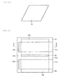
- FIG 3 is a plan view showing a schematic constitution of the unit module of FIG 1 .
- a cross-section taken on line II-II of FIG 3 corresponds to FIGS 1 and 2 .
- a single cell constituting the battery structure part includes a fuel electrode layer 11 and an air electrode layer 13. Although not shown, a solid electrolyte layer is interposed between a fuel electrode layer 11 and an air electrode layer 13.
- the gas supply channel structure part 21b which is a part of the support structure 20
- one fuel gas supply channel 23 as an anode gas supply channel for supplying a fuel gas to the cell and one air supply channel 24 as a cathode gas supply channel for supplying air to the cell are formed.
- Each of the fuel gas supply channel 23 and the air supply channel 24 is formed in the form of an opening which extends in one direction, that is, a long and thin through-hole. In other words, each of the fuel gas supply channel 23 and the air supply channel 24 has a roughly rectangular cross-section.
- the fuel gas supply channel 23 is arranged so as to be in contact with a side surface on one side (left side in FIG 3 ) of the fuel electrode layer 11.
- the air supply channel 24 is arranged so as to be in contact with a side surface on one side (upper side in FIG 3 ) of the air electrode layer 13. That is, the fuel gas supply channel 23 shown in FIG 3 corresponds to a first anode gas supply channel part, at least a part of the inner wall surface of which is formed of the fuel electrode layer 11. Further, the air supply channel 24 shown in FIG 3 corresponds to a first cathode gas supply channel part, at least a part of the inner wall surface of which is formed of the air electrode layer 13.
- the fuel gas flows rightward from the fuel gas supply channel 23 arranged on a left side to the fuel electrode layer 11.
- the air flows downward from the air supply channel 24 arranged on an upper side to the air electrode layer 13.
- a stream of a fuel gas and a stream of air are orthogonal to each other.
- the fuel gas supply channel 23 and the air supply channel 24 are arranged at the outside of the battery structure part.
- the support structure 20 is composed of a laminate of a portion 20b, a portion 20a and a portion 20c.
- the portion 20a is composed of a laminate of a portion 20a3, a portion 20a1 and a portion 20a2.
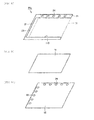
- the portion 20a1 has a shape shown in FIG 4
- the portion 20a2 has a shape shown in FIG 5
- the portion 20a3 has a shape shown in FIG 6 .
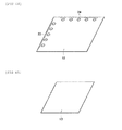
- the portion 20b has a shape shown in FIG 7
- the air supply channel 24 is formed by fitting the air electrode layer 13 shown in FIG 11 in the portion 20b.
- the portion 20c has a shape shown in FIG 8
- the fuel gas supply channel 23 is formed by fitting the fuel electrode layer 11 shown in FIG 9 in the portion 20c.
- the fuel gas supply channel 23 and the air supply channel 24 are formed in the solid electrolyte layer 12.
- each of the fuel gas supply channel 23 and the air supply channel 24 is formed in the form of a plurality of openings which are arranged at intervals in one direction, that is, a plurality of circular through-holes. That is, each of the fuel gas supply channel 23 and the air supply channel 24 has a plurality of roughly circular cross-sections arranged at intervals.
- the fuel gas supply channel 23 has a roughly rectangular cross-section, and the air supply channel 24 has a plurality of roughly circular cross-sections arranged at intervals.
- the fuel gas distribution channel forming layers 231a, 231b and 231c disappear after firing, and thereby, these layers become fuel gas distribution channels which lead to a fuel gas supply channel 23 for supplying a fuel gas to the fuel electrode layer 11 and distribute a fuel gas to the fuel electrode layer 11.
- a portion between the fuel gas distribution channel forming layers 231a, 231b and 231c is a portion which forms a wall of fuel gas distribution channels, and the portion is referred to as a rib.
- the air supply channel 24 has a roughly rectangular cross-section, and the fuel gas supply channel 23 has a plurality of roughly circular cross-sections arranged at intervals.
- the air distribution channel forming layers 241a, 241b and 241c disappear after firing, and thereby, these layers become air distribution channels which lead to an air supply channel 24 for supplying air to the fuel electrode layer 13 and distribute air to the air electrode layer 13.
- a portion between the air distribution channel forming layers 241a, 241b and 241c is a portion which forms a wall of air distribution channels, and the portion is referred to as a rib.
- the air supply channel 24 has a roughly rectangular cross-section, and the fuel gas supply channel 23 has a plurality of roughly circular cross-sections arranged at intervals.
- the air supply channel 24 at least a part of the inner wall surface is formed of the air electrode layer 13.
- the fuel gas supply channel 23 has a roughly rectangular cross-section, and the air supply channel 24 has a plurality of roughly circular cross-sections arranged at intervals.
- the fuel gas supply channel 23 at least a part of the inner wall surface is formed of the fuel electrode layer 11.
- each of the fuel gas supply channel 23 and the air supply channel 24 has a plurality of roughly circular cross-sections arranged at intervals.
- the fuel gas supply channel 23 shown in FIG 8 corresponds to a first anode gas supply channel part, at least a part of the inner wall surface of which is formed of the fuel electrode layer 11, and the air supply channel 24 shown in FIG 7 corresponds to a first cathode gas supply channel part, at least a part of the inner wall surface of which is formed of the air electrode layer 13.
- the fuel gas supply channel 23 shown in FIGS 4 , 6 , 7 and 10 corresponds to at least a part of the second anode gas supply channel part other than the first anode gas supply channel part.
- the air supply channel 24 shown in FIGS 4 , 5 , 8 and 10 corresponds to at least a part of the second cathode gas supply channel part other than the first cathode gas supply channel part.
- the cross-section area (an area of a roughly rectangular cross-section) of the fuel gas supply channel 23 (the first anode gas supply channel part) shown in FIG 8 is larger than the cross-section area (total areas of roughly circular cross-sections) of the fuel gas supply channel 23 (at least a part of the second anode gas supply channel part) shown in FIGS 4 , 6 , 7 and 10 .
- the cross-section area (an area of a roughly rectangular cross-section) of the air supply channel 24 (the first cathode gas supply channel part) shown in FIG 7 is larger than the cross-section area (total areas of roughly circular cross-sections) of the air supply channel 24 (at least a part of the second cathode gas supply channel part) shown in FIGS 4 , 5 , 8 and 10 .
- the cross-section area of the fuel gas supply channel 23 formed in the fuel electrode layer 11 to which the fuel gas is supplied is larger than the cross-section area of at least a part of the fuel gas supply channel 23 other than the above-mentioned fuel gas supply channel 23, and the cross-section area of the air supply channel 24 formed in the air electrode layer 13 to which the air is supplied, is larger than the cross-section area of at least a part of the air supply channel 24 other than the above-mentioned air supply channel 24.
- the gas can be equally-distributed and supplied to the fuel electrode layer 11 and the air electrode layer 13 through the fuel gas supply channel 23 and the air supply channel 24, which are formed in a cell and have a large cross-section area. Further, since at least parts of the fuel gas supply channel 23 and the air supply channel 24, which are respectively formed in a portion other than a cell, have a small cross-section area, it is possible to prevent the strength from being reduced due to formation of the supply channel in the solid electrolyte fuel battery 100 in which a gas supply channel and a cell are integrally formed.
- At least one of a ratio of the cross-section area of the fuel gas supply channel 23 formed in a cell to the cross-section area of at least a part of the fuel gas supply channel 23 formed in a portion other than a cell, and a ratio of the cross-section area of the air supply channel 24 formed in a cell to the cross-section area of at least a part of the air supply channel 24 formed in a portion other than a cell is 1.1 or more and 14 or less.
- the ratio is more than 1.1, the strength of the cell is increased.
- the ratio is less than 14, the effect of a pressure loss on the channel is small, and a gas can be evenly flown in the channel.
- At least one of a ratio of the cross-section area of the fuel gas supply channel 23 formed in a cell to the cross-section area of at least a part of the fuel gas supply channel 23 formed in a portion other than a cell, and a ratio of the cross-section area of the air supply channel 24 formed in a cell to the cross-section area of at least a part of the air supply channel 24 formed in a portion other than a cell is 2 or more and 10 or less.
- the ratio is more than 2
- the strength of the cell is adequately increased.
- the ratio is less than 10 the effect of a pressure loss on the channel can be substantially neglected.
- Embodiment 1 not only the cross-section area of the fuel gas supply channel 23, at least a part of the inner wall surface of which is formed of the fuel electrode layer 11, as shown in FIG 8 , but also the cross-section area (an area of a roughly rectangular cross-section) of the fuel gas supply channel 23 formed in the portions 20a2 and 20c of the support structure 20 in contact with the fuel electrode layer 11, as shown in FIGS 5 and 8 , is larger than the cross-section area (total areas of roughly circular cross-sections) of the fuel gas supply channel 23 shown in FIGS 4 , 6 , 7 and 10 .
- the cross-section area of the air supply channel 24 is larger than the cross-section area (total areas of roughly circular cross-sections) of the air supply channel 24 (at least a part of the second cathode gas supply channel part) shown in FIGS 4 , 5 , 8 and 10 .
- FIG 12 is a plan view showing a schematic constitution of the unit module of FIG 1 .
- a cross-section taken on line II-II of FIG 12 corresponds to FIGS 1 and 2 .
- a single cell constituting the battery structure part includes two fuel electrode layers 11a and 11b and two air electrode layers 13a and 13b.
- a solid electrolyte layer is interposed between two fuel electrode layers 11a, 11b and two air electrode layers 13a, 13b.
- the gas supply channel structure part 21b which is a part of the support structure 20
- two fuel gas supply channels 23a and 23b as an anode gas supply channel for supplying a fuel gas to the cell and one air supply channel 24 as an cathode gas supply channel for supplying air to the cell are formed.
- Each of the fuel gas supply channels 23a, 23b and the air supply channel 24 is formed in the form of an opening which extends in one direction, that is, a long and thin through-hole.
- each of the fuel gas supply channels 23a and 23b and the air supply channel 24 has a roughly rectangular cross-section.
- the fuel gas supply channel 23a is arranged so as to be in contact with a side surface on one side (left side in FIG 12 ) of the fuel electrode layer 11a, and the fuel gas supply channel 23b is arranged so as to be in contact with a side surface on one side (left side in FIG 12 ) of the fuel electrode layer 11b.
- the air supply channel 24 is interposed between the air electrode layer 13a and the air electrode layer 13b, and arranged so as to be in contact with a side surface on one side (lower side in FIG 12 ) of the air electrode layer 13a, and arranged so as to be in contact with a side surface on one side (upper side in FIG 12 ) of the air electrode layer 13b. Because of this arrangement, the air supply channel 24 is arranged within the battery structure part.
- the fuel gas supply channels 23a and 23b shown in FIG 12 corresponds to a first anode gas supply channel part, at least a part of the inner wall surface of which is formed of the fuel electrode layer 11. Further, the air supply channel 24 shown in FIG 12 corresponds to a first cathode gas supply channel part, at least a part of the inner wall surface of which is formed of the air electrode layer 13.
- the fuel gas flows rightward from the fuel gas supply channels 23a and 23b arranged on a left side to the fuel electrode layers 11a and 11b, respectively.
- the air flows upward from the air supply channel 24 arranged within or in the central part of the battery structure part to the air electrode layer 13a, and flows downward from the air supply channel 24 to the air electrode layer 13b.
- a stream of a fuel gas and a stream of air are orthogonal to each other.
- the portion 20a1 has a shape shown in FIG 13
- the portion 20a2 has a shape shown in FIG 14
- the portion 20a3 has a shape shown in FIG 15
- the portion 20b has a shape shown in FIG 16
- the air supply channel 24 is formed by fitting the air electrode layers 13a and 13b shown in FIG 20 in the portion 20b
- the portion 20c has a shape shown in FIG 17
- the fuel gas supply channels 23a and 23b are formed by fitting the fuel electrode layers 11a and 11b shown in FIG 18 in the portion 20c.
- the fuel gas supply channels 23a and 23b, and the air supply channel 24 are formed in the solid electrolyte layer 12.
- each of the fuel gas supply channels 23a, 23b and the air supply channel 24 is formed in the form of a plurality of openings which are arranged at intervals in one direction, that is, a plurality of circular through-holes. That is, each of the fuel gas supply channels 23a and 23b, and the air supply channel 24 has a plurality of roughly circular cross-sections arranged at intervals.
- each of the fuel gas supply channels 23a and 23b has a roughly rectangular cross-section, and the air supply channel 24 has a plurality of roughly circular cross-sections arranged at intervals.
- the fuel gas distribution channel forming layers 231a and 231b disappear after firing, and thereby, these layers become fuel gas distribution channels which lead to a fuel gas supply channel 23 for supplying a fuel gas to the fuel electrode layer 11 and distribute a fuel gas to the fuel electrode layer 11.
- a portion between the fuel gas distribution channel forming layers 231a and 231b is a portion which forms a wall of fuel gas distribution channels, and the portion is referred to as a rib.
- the air supply channel 24 has a roughly rectangular cross-section, and each of the fuel gas supply channels 23a and 23b has a plurality of roughly circular cross-sections arranged at intervals.
- the air distribution channel forming layers 241a, 241b and 241c disappear after firing, and thereby, these layers become air distribution channels which lead to an air supply channel 24 for supplying air to the air electrode layer 13 and distribute air to the air electrode layer 13.
- a portion between the air distribution channel forming layers 241a, 241b and 241c is a portion which forms a wall of air distribution channels, and the portion is referred to as a rib.
- the air supply channel 24 has a roughly rectangular cross-section, and each of the fuel gas supply channels 23a and 23b has a plurality of roughly circular cross-sections arranged at intervals.
- the air supply channel 24 at least a part of the inner wall surface is formed of the air electrode layers 13a and 13b.
- each of the fuel gas supply channels 23a and 23b has a roughly rectangular cross-section, and the air supply channel 24 has a plurality of roughly circular cross-sections arranged at intervals.
- the fuel gas supply channels 23a and 23b at least parts of the inner wall surfaces are formed of the fuel electrode layers 11a and 11b.
- each of the fuel gas supply channels 23a and 23b, and the air supply channel 24 has a plurality of roughly circular cross-sections arranged at intervals.
- the fuel gas supply channels 23a and 23b shown in FIG 17 correspond to first anode gas supply channel parts, at least parts of the inner wall surfaces of which are formed of the fuel electrode layers 11a and 11b
- the air supply channel 24 shown in FIG 16 corresponds to a first cathode gas supply channel part, at least a part of the inner wall surface of which is formed of the air electrode layers 13a and 13b.
- the fuel gas supply channels 23a and 23b shown in FIGS 13, 15 , 16 and 19 correspond to at least a part of the second anode gas supply channel part other than the first anode gas supply channel part.
- the air supply channel 24 shown in FIGS 13, 14 , 17 and 19 corresponds to at least a part of the second cathode gas supply channel part other than the first cathode gas supply channel part.
- the cross-section areas (total areas of roughly rectangular cross-sections) of the fuel gas supply channels 23a and 23b (the first anode gas supply channel part) shown in FIG 17 are larger than the cross-section areas (total areas of roughly circular cross-sections) of the fuel gas supply channels 23a and 23b (at least a part of the second anode gas supply channel part) shown in FIGS 13, 15 , 16 and 19 .
- the cross-section area (an area of a roughly rectangular cross-section) of the air supply channel 24 (the first cathode gas supply channel part) shown in FIG 16 is larger than the cross-section area (total areas of roughly circular cross-sections) of the air supply channel 24 (at least a part of the second cathode gas supply channel part) shown in FIGS 13, 14 , 17 and 19 .
- the solid electrolyte fuel battery 100 of Embodiment 2 can achieve the same operation and effect as in Embodiment 1 described above.
- At least one of a ratio of the cross-section area of the fuel gas supply channel 23a, 23b formed in a cell to the cross-section area of at least a part of the fuel gas supply channel 23a, 23b formed in a portion other than a cell, and a ratio of the cross-section area of the air supply channel 24 formed in a cell to the cross-section area of at least a part of the air supply channel 24 formed in a portion other than a cell is 1.1 or more and 14 or less.
- At least one of a ratio of the cross-section area of the fuel gas supply channel 23a, 23b formed in a cell to the cross-section area of at least a part of the fuel gas supply channel 23a, 23b formed in a portion other than a cell, and a ratio of the cross-section area of the air supply channel 24 formed in a cell to the cross-section area of at least a part of the air supply channel 24 formed in a portion other than a cell is 2 or more and 10 or less. Also in this case, the same operation and effect as in Embodiment 1 described above can be achieved.
- Embodiment 2 not only the cross-section areas of the fuel gas supply channels 23a and 23b, at least parts of the inner wall surfaces of which are formed of the fuel electrode layers 11a and 11b, as shown in FIG 17 , but also the cross-section areas (total areas of roughly rectangular cross-sections) of the fuel gas supply channels 23a and 23b respectively formed in the portions 20a2 and 20c of the support structure 20 in contact with the fuel electrode layers 11a and 11b, as shown in FIGS 14 and 17 , are larger than the cross-section areas (total areas of roughly circular cross-sections) of the fuel gas supply channels 23a and 23b shown in FIGS 13, 15 , 16 and 19 .
- the cross-section area of the air supply channel 24 is larger than the cross-section area (total areas of roughly circular cross-sections) of the air supply channel 24 (at least a part of the second cathode gas supply channel part) shown in FIGS 13, 14 , 17 and 19 .
- FIG 21 is a plan view showing a schematic constitution of the unit module of FIG 1 .
- a cross-section taken on line II-II of FIG 21 corresponds to FIGS 1 and 2 .
- a single cell constituting the battery structure part includes four fuel electrode layers 11a, 11b, 11c and 11d and four air electrode layers 13a, 13b, 13c and 13d.
- a solid electrolyte layer is interposed between four fuel electrode layers 11a, 11b, 11c, 11d and four air electrode layers 13a, 13b, 13c, 13d.
- the gas supply channel structure part 21b which is a part of the support structure 20
- two fuel gas supply channels 23a and 23b as an anode gas supply channel for supplying a fuel gas to the cell and two air supply channels 24a and 24b as an cathode gas supply channel for supplying air to the cell are formed.
- Each of the fuel gas supply channels 23a, 23b and the air supply channels 24a, 24b is formed in the form of an opening which extends in one direction, that is, a long and thin through-hole.
- each of the fuel gas supply channels 23a and 23b and the air supply channels 24a and 24b has a roughly rectangular cross-section.
- the fuel gas supply channel 23a is interposed between the fuel electrode layer 11a and the fuel electrode layer 11b, and arranged so as to be in contact with a side surface on one side (right side in FIG 21 ) of the fuel electrode layer 11a, and arranged so as to be in contact with a side surface on one side (left side in FIG 21 ) of the fuel electrode layer 11b.
- the fuel gas supply channel 23b is interposed between the fuel electrode layer 11c and the fuel electrode layer 11d, and arranged so as to be in contact with a side surface on one side (right side in FIG 21 ) of the fuel electrode layer 11c, and arranged so as to be in contact with a side surface on one side (left side in FIG 21 ) of the fuel electrode layer 11d. Because of this arrangement, the fuel gas supply channel 23 is arranged within the battery structure part.
- the air supply channel 24a is interposed between the air electrode layer 13a and the air electrode layer 13b, and arranged so as to be in contact with a side surface on one side (lower side in FIG 21 ) of the air electrode layer 13a, and arranged so as to be in contact with a side surface on one side (upper side in FIG 21 ) of the air electrode layer 13c.
- the air supply channel 24b is interposed between the air electrode layer 13b and the air electrode layer 13d, and arranged so as to be in contact with a side surface on one side (lower side in FIG 21 ) of the air electrode layer 13b, and arranged so as to be in contact with a side surface on one side (upper side in FIG 21 ) of the air electrode layer 13d. Because of this arrangement, the air supply channel 24 is arranged within the battery structure part.
- the fuel gas supply channels 23a and 23b shown in FIG 21 correspond to first anode gas supply channel parts, at least parts of the inner wall surfaces of which are formed of the fuel electrode layer 11. Further, the air supply channel 24 shown in FIG 21 corresponds to a first cathode gas supply channel part, at least a part of the inner wall surface of which is formed of the air electrode layer 13.
- the fuel gas flows rightward and leftward from each of the fuel gas supply channels 23a and 23b arranged within or in the central part of the battery structure part to each of the fuel electrode layers 11a, 11b, 11c and 11d.
- the air flows upward and downward from each of the air supply channels 24a and 24b arranged within or in the central part of the battery structure part to each of the air electrode layers 13a, 13b, 13c and 13d.
- a stream of a fuel gas and a stream of air are orthogonal to each other.
- the portion 20a1 has a shape shown in FIG 22
- the portion 20a2 has a shape shown in FIG 23
- the portion 20a3 has a shape shown in FIG 24
- the portion 20b has a shape shown in FIG 25
- the air supply channels 24a and 24b are formed by fitting the air electrode layers 13a, 13b, 13c and 13d shown in FIG 29 in the portion 20b
- the portion 20c has a shape shown in FIG 26
- the fuel gas supply channels 23a and 23b are formed by fitting the fuel electrode layers 11a, 11b, 11c and 11d shown in FIG 27 in the portion 20c.
- the fuel gas supply channels 23a and 23b, and the air supply channels 24a and 24b are formed in the solid electrolyte layer 12.
- each of the fuel gas supply channels 23a, 23b and the air supply channels 24a, 24b is formed in the form of a plurality of openings which are arranged at intervals in one direction, that is, a plurality of circular through-holes. That is, each of the fuel gas supply channels 23a and 23b, and the air supply channels 24a and 24b has a plurality of roughly circular cross-sections arranged at intervals.
- each of the fuel gas supply channels 23a and 23b has a roughly rectangular cross-section, and each of the air supply channels 24a and 24b has a plurality of roughly circular cross-sections arranged at intervals.
- the fuel gas distribution channel forming layers 231a and 231b disappear after firing, and thereby, these layers become fuel gas distribution channels which lead to fuel gas supply channels 23a and 23b for supplying a fuel gas to the fuel electrode layer 11 and distribute a fuel gas to the fuel electrode layer 11.
- a portion between the fuel gas distribution channel forming layers 231a and 231b is a portion which forms a wall of fuel gas distribution channels, and the portion is referred to as a rib.
- each of the air supply channels 24a and 24b has a roughly rectangular cross-section, and each of the fuel gas supply channels 23a and 23b has a plurality of roughly circular cross-sections arranged at intervals.
- the air distribution channel forming layers 241a and 241b disappear after firing, and thereby, these layers become air distribution channels which lead to air supply channels 24a and 24b for supplying air to the air electrode layer 13 and distribute air to the air electrode layer 13.
- a portion between the air distribution channel forming layers 241a and 241b is a portion which forms a wall of air distribution channels, and the portion is referred to as a rib.
- each of the air supply channels 24a and 24b has a roughly rectangular cross-section, and each of the fuel gas supply channels 23a and 23b has a plurality of roughly circular cross-sections arranged at intervals.
- at least parts of the inner wall surfaces are formed of the air electrode layers 13a, 13b, 13c and 13d.
- each of the fuel gas supply channels 23a and 23b has a roughly rectangular cross-section, and each of the air supply channels 24a and 24b has a plurality of roughly circular cross-sections arranged at intervals.
- at least parts of the inner wall surfaces are formed of the fuel electrode layers 11a, 11b, 11c and 11d.
- each of the fuel gas supply channels 23a and 23b, and the air supply channels 24a and 24b has a plurality of roughly circular cross-sections arranged at intervals.
- the fuel gas supply channels 23a and 23b shown in FIG 26 correspond to first anode gas supply channel parts, at least parts of the inner wall surfaces of which are formed of the fuel electrode layers 11a and 11b
- the air supply channels 24a and 24b shown in FIG 25 correspond to first cathode gas supply channel parts, at least parts of the inner wall surfaces of which are formed of the air electrode layers 13a and 13b.
- the fuel gas supply channels 23a and 23b shown in FIGS 22 , 24 , 25 and 28 correspond to at least a part of the second anode gas supply channel part other than the first anode gas supply channel part.
- the air supply channel 24 shown in FIGS 22 , 23 , 26 and 28 corresponds to at least a part of the second cathode gas supply channel part other than the first cathode gas supply channel part.
- the cross-section areas (total areas of roughly rectangular cross-sections) of the fuel gas supply channels 23a and 23b (the first anode gas supply channel part) shown in FIG 26 are larger than the cross-section areas (total areas of roughly circular cross-sections) of the fuel gas supply channels 23a and 23b (at least a part of the second anode gas supply channel part) shown in FIGS 22 , 24 , 25 and 28 .
- the cross-section areas (total areas of roughly rectangular cross-sections) of the air supply channels 24a and 24b (the first cathode gas supply channel part) shown in FIG 25 are larger than the cross-section areas (total areas of roughly circular cross-sections) of the air supply channels 24a and 24b (at least a part of the second cathode gas supply channel part) shown in FIGS 22 , 23 , 26 and 28 .
- the solid electrolyte fuel battery 100 of Embodiment 3 can achieve the same operation and effect as in Embodiment 1 described above.
- Embodiment 3 not only the cross-section areas of the fuel gas supply channels 23a and 23b, at least parts of the inner wall surfaces of which are formed of the fuel electrode layers 11a and 11b, as shown in FIG 26 , but also the cross-section areas (total areas of roughly rectangular cross-sections) of the fuel gas supply channels 23a and 23b respectively formed in the portions 20a2 and 20c of the support structure 20 in contact with the fuel electrode layers 11a and 11b, as shown in FIGS 23 and 26 , are larger than the cross-section areas (total areas of roughly circular cross-sections) of the fuel gas supply channels 23a and 23b shown in FIGS 22 , 24 , 25 and 28 .
- the cross-section areas of the air supply channels 24a and 24b are larger than the cross-section areas (total areas of roughly circular cross-sections) of the air supply channels 24a and 24b (at least a part of the second cathode gas supply channel part) shown in FIGS 22 , 23 , 26 and 28 .
- the gas supply channel structure part 21b and the intercellular separation part 21a are integrally formed.
- the gas supply channel structure part 21b serving the function of a manifold and the intercellular separation part 21a serving the function of a separator are integrally formed, a portion serving the dual function of a separator and a manifold is continuously formed. Therefore, sealing members between separators and between the cells and the manifold, which are required in conventional solid electrolyte fuel batteries, become unnecessary. Thereby, a sealing property to a gas as a whole battery can be enhanced and the number of parts can be reduced, and consequently the number of process steps can be reduced.
- the gas supply channel structure part 21b and the solid electrolyte layer 12 are integrally formed.
- fuel gas supply channels 23, 23a, 23b and air supply channels 24, 24a, 24b are formed so as to have roughly rectangular or roughly circular cross-sections
- a cross-section shape of the channel is not limited, and various geometrical planar shape may be employed.
- Example 1 in which a solid electrolyte fuel battery of the present invention was prepared based on Embodiment 1 described above, and Comparative Examples 1 and 2 in which solid electrolyte fuel batteries were prepared in order to compare with a structure of the present invention will be described.
- material powders of members constituting the unit module of a solid electrolyte fuel battery of Embodiment 1 shown in FIGS 1 to 3 were prepared as follows.
- Fuel electrode layer 11 A mixture of 60% by weight of nickel oxide (NiO) and 40% by weight of zirconia (ZrO 2 ) stabilized with scandia (Sc 2 O 3 ) added in an amount 10 mole % and ceria (CeO 2 ) added in an amount 1 mole % (scandia ceria stabilized zirconia: ScCeSZ)
- Solid electrolyte layer 12 Zirconia (ZrO 2 ) stabilized with scandia (Sc2O3) added in an amount 10 mole % and ceria (CeO 2 ) added in an amount 1 mole % (scandia ceria stabilized zirconia: ScCeSZ)
- Air electrode layer 13 A mixture of 60% by weight of La 0.s Sr 0.2 MnO 3 and 40% by weight of zirconia (ZrO 2 ) stabilized with scandia (Sc 2 O 3 ) added in an amount 10 mole % and ceria (CeO 2 ) added in an amount 1 mole % (scandia ceria stabilized zirconia: ScCeSZ)
- the portion 20a is configured by laminating a portion 20a2 (refer to FIG 5 ), a portion 20a1 (refer to FIG 4 ) and a portion 20a3 (refer to FIG 6 ) in this order from the bottom.
- the portion 20b is shown in FIG 7 .
- the portion 20c is shown in FIG 8 .
- an electrically insulating material powder, a polyvinyl butyral-based binder and a mixture of ethanol and toluene (mixing ratio is 1 : 4 by weight) as an organic solvent were mixed, and the resulting mixture was applied by a doctor blade method to prepare green sheets for the portions 20a1, 20a2 and 20a3 of the solid electrolyte fuel battery support structure 20.
- a plurality of through-holes for forming electrical conductors 22 in an electrically insulating body 21 was prepared.
- a conductive paste-filled layer for forming the electrical conductors 22 was prepared by filling these through-holes with a paste composed of 70% by weight of silver and 30% by weight of palladium.
- circular through-holes, and long and thin rectangular through-holes were formed in the portions 20a1, 20a2 and 20a3 in order to form the fuel gas supply channel 23 and the air supply channel 24.
- the circular through-hole had a diameter of 4.5 mm, and five through-holes were evenly arranged at intervals of 12 mm. Accordingly, the total area of the circular through-holes was about 80 mm 2 .
- the rectangular through-hole was 4.5 mm wide and 61.5 mm long. Accordingly, the area of the rectangular through-hole was about 277 mm 2 .
- fuel gas distribution channel forming layers 231a and 231b made of polyethylene terephthalate (PET) were formed so as to connect to the through-hole for forming the fuel gas supply channel 23.
- PET polyethylene terephthalate
- the fuel gas distribution channel forming layers 231a and 231b disappear after firing, and thereby, these layers become fuel gas distribution channels which lead to a fuel gas supply channel 23 for supplying a fuel gas and distribute a fuel gas to the fuel electrode layer 11.
- FIG 5 illustrates as if three fuel gas distribution channels are formed, but in fact, many fuel gas distribution channels of 0.8 mm wide and 61.5 mm long were arranged at 0.8 mm intervals (ribs).
- FIG 6 illustrates as if three air distribution channels are formed, but in fact, many fuel gas distribution channels of 0.8 mm wide and 61.5 mm long were arranged at 0.8 mm intervals (ribs).
- an electrically insulating material powder, a polyvinyl butyral-based binder and a mixture of ethanol and toluene (mixing ratio is 1 : 4 by weight) as an organic solvent were mixed, and the resulting mixture was applied by a doctor blade method to prepare a green sheet for the portion 20b of the solid electrolyte fuel battery support structure 20.
- a sheet made of a nearly U-shaped electrically insulating body 21 was prepared so that a green sheet for the air electrode layer 13 can be fit in a clearance by making the clearance for forming the air supply channel 24 shown in FIG 3 .
- a circular through-hole having a size similar to the above was prepared in the green sheet for the portion 20b.
- an electrically insulating material powder, a polyvinyl butyral-based binder and a mixture of ethanol and toluene (mixing ratio is 1 : 4 by weight) as an organic solvent were mixed, and the resulting mixture was applied by a doctor blade method to prepare a green sheet for the portion 20c of the solid electrolyte fuel battery support structure 20.
- a sheet made of a nearly U-shaped electrically insulating body 21 was prepared so that a green sheet for the fuel electrode layer 11 can be fit in a clearance by making the clearance for forming the fuel gas supply channel 23 shown in FIG 3 . Further, in order to form the air supply channel 24 in the electrically insulating body 21, as shown in FIG 8 , a circular through-hole having a size similar to the above was prepared in the green sheet for the portion 20c.
- green sheets for an air electrode layer 13 and a fuel electrode layer 11 respectively shown in FIG 3 were prepared in the following manner.
- Powders of materials of a fuel electrode layer 11 and an air electrode layer 13, a polyvinyl butyral-based binder and a mixture of ethanol and toluene (mixing ratio is 1 : 4 by weight) as an organic solvent were mixed, and the resulting mixtures were respectively applied by a doctor blade method to prepare green sheets for the fuel electrode layer 11 and the air electrode layer 13, respectively.
- a powder of a material of a solid electrolyte layer 12, a polyvinyl butyral-based binder and a mixture of ethanol and toluene (mixing ratio is 1 : 4 by weight) as an organic solvent were mixed, and the resulting mixture was applied by a doctor blade method to prepare a green sheet for the solid electrolyte layer 12.
- a green sheet for the fuel electrode layer 11 was prepared in a shape shown in FIG 9
- a green sheet for the solid electrolyte layer 12 was prepared in a shape shown in FIG 10
- a green sheet for the air electrode layer 13 was prepared in a shape shown in FIG 11 .
- long and thin rectangular through-holes having a size similar to the above for forming the fuel gas supply channel 23 and the air supply channel 24 were formed in the green sheet for the solid electrolyte layer 12.
- the resulting laminate was subjected to cold isostatic pressing at a temperature of 80°C and at a pressure of 1000 kgf/cm 2 for 2 minutes to be press-bonded.
- the press-bonded body was subjected to a degreasing treatment in a range of 400°C to 500°C and then retained at temperatures of from 1000°C to 1300°C for 2 hours to be fired.
- a sample (plane area: 85 mm x 85 mm) of a solid electrolyte fuel battery of Example 1 was prepared in this way.
- the cross-section area (an area of one rectangular cross-section: about 277 mm 2 ) of the fuel gas supply channel 23 formed in the fuel electrode layer 11 to which the fuel gas is supplied is larger than the cross-section area (a total area of five circular cross-sections: about 80 mm 2 ) of at least a part of the fuel gas supply channel 23 other than the above-mentioned fuel gas supply channel 23, and the cross-section area (an area of one rectangular cross-section: about 277 mm 2 ) of the air supply channel 24 formed in the air electrode layer 13 to which the air is supplied, is larger than the cross-section area (a total area of five circular cross-sections: about 80 mm 2 ) of at least a part of the air supply channel 24 other than the above-mentioned air supply channel 24.
- the material powders of the fuel electrode layer 11, the solid electrolyte layer 12, the air electrode layer 13 and portions 20a to 20c, which were respectively members constituting the unit module of a solid electrolyte fuel battery shown in FIGS 1, 2 and 3 were prepared in the same manner as in Example 1.
- the portion 20a is configured by laminating a portion 20a2 (refer to FIG 31 ), a portion 20a1 (refer to FIG 30 ) and a portion 20a3 (refer to FIG 32 ) in this order from the bottom.
- a portion 20b is shown in FIG 33 .
- a portion 20c is shown in FIG 34 .
- Green sheets for the portions 20a1, 20a2, and 20a3 were prepared in the same manner as in Example 1.
- a conductive paste-filled layer for forming a plurality of electrical conductors 22 in an electrically insulating body 21 was prepared in the same manner as in Example 1.
- fuel gas distribution channel forming layers 231a, 231b and 231c made of polyethylene terephthalate (PET) were formed so as to connect to the through-hole for forming the fuel gas supply channel 23.
- PET polyethylene terephthalate
- the fuel gas distribution channel forming layers 231a, 231b and 231c disappear after firing, and thereby, these layers become fuel gas distribution channels which lead to a fuel gas supply channel 23 for supplying a fuel gas and distribute a fuel gas to the fuel electrode layer 11.
- a size and arrangement of the fuel gas distribution channel, and the number of the fuel gas distribution channels are the same as those of Example 1.
- air distribution channel forming layers 241a, 241b and 241c made of polyethylene terephthalate (PET) were formed so as to connect to the through-hole for forming the air supply channel 24.
- PET polyethylene terephthalate
- the air distribution channel forming layers 241a, 241b and 241c disappear after firing, and thereby, these layers become air distribution channels which lead to an air supply channel 24 for supplying air and distribute air to the air electrode layer 13.
- a size and arrangement of the air distribution channel, and the number of the air distribution channels are the same as those of Example 1.
- a sheet made of an electrically insulating body 21 having such a shape as shown in FIG 33 was prepared so that a green sheet for the air electrode layer 13 can be fit in a clearance by making the clearance for forming the air supply channel 24 shown in FIG 3 .
- a long and thin rectangular through-hole for forming the fuel gas supply channel 23 in the electrically insulating body 21 was formed in the green sheet for the portion 20b.
- a size of the rectangular through-hole is the same as in Example 1.
- a sheet made of an electrically insulating body 21 having such a shape as shown in FIG 34 was prepared so that a green sheet for the fuel electrode layer 11 can be fit in a clearance by making the clearance for forming the fuel gas supply channel 23 shown in FIG 3 .
- a long and thin rectangular through-hole for forming the air supply channel 24 in the electrically insulating body 21 was prepared in the green sheet for the portion 20c.
- a size of the rectangular through-hole is the same as in Example 1.
- a green sheet for the fuel electrode layer 11 was prepared in a shape shown in FIG 35
- a green sheet for the solid electrolyte layer 12 was prepared in a shape shown in FIG 36
- a green sheet for the air electrode layer 13 was prepared in a shape shown in FIG 37 .
- long and thin rectangular through-holes for forming the fuel gas supply channel 23 and the air supply channel 24 were formed in the green sheet for the solid electrolyte layer 12.
- a size of the rectangular through-hole is the same as in Example 1.
- Example 2 The resulting laminate was subjected to cold isostatic pressing to be press-bonded in the same manner as in Example 1.
- the press-bonded body was subjected to a degreasing treatment and then fired in the same manner as in Example 1.
- a sample (plane area: 85 mm ⁇ 85 mm) of a solid electrolyte fuel battery of Comparative Example 1 was prepared in this way.
- each of cross-sections of all fuel gas supply channels 23 and air supply channels 24 is one rectangular cross-section. Accordingly, the cross-section area (an area of one rectangular cross-section: about 277 mm 2 ) of the fuel gas supply channel 23 formed in the fuel electrode layer 11 to which the fuel gas is supplied, is equal to the cross-section area (an area of one rectangular cross-section: about 277 mm 2 ) of at least a part of the fuel gas supply channel 23 other than the above-mentioned fuel gas supply channel 23, and the cross-section area (an area of one rectangular cross-section: about 277 mm 2 ) of the air supply channel 24 formed in the air electrode layer 13 to which the air is supplied, is equal to the cross-section area (an area of one rectangular cross-section: about 277 mm 2 ) of at least a part of the air supply channel 24 other than the above-mentioned air supply channel 24.
- the material powders of the fuel electrode layer 11, the solid electrolyte layer 12, the air electrode layer 13 and portions 20a to 20c, which were respectively members constituting the unit module of a solid electrolyte fuel battery shown in FIGS 1 and 2 were prepared in the same manner as in Example 1.
- the portion 20a is configured by laminating a portion 20a2 (refer to FIG 39 ), a portion 20a1 (refer to FIG 38 ) and a portion 20a3 (refer to FIG 40 ) in this order from the bottom.
- a portion 20b is shown in FIG 41 .
- a portion 20c is shown in FIG 42 .
- Green sheets for the portions 20a1, 20a2 and 20a3 were prepared in the same manner as in Example 1.
- a conductive paste-filled layer for forming a plurality of electrical conductors 22 in an electrically insulating body 21 was prepared in the same manner as in Example 1.
- circular through-holes were formed in the portions 20a1, 20a2 and 20a3 in order to form the fuel gas supply channel 23 and the air supply channel 24.
- a size and arrangement of the circular through-hole, and the number of the circular through-holes are the same as those of Example 1.
- fuel gas distribution channel forming layers 231a, 231b and 231c made of polyethylene terephthalate (PET) were formed so as to connect to through-holes for forming the fuel gas supply channel 23.
- PET polyethylene terephthalate
- the fuel gas distribution channel forming layers 231a, 231b and 231c disappear after firing, and thereby, these layers become fuel gas distribution channels which lead to a fuel gas supply channel 23 for supplying a fuel gas and distribute a fuel gas to the fuel electrode layer 11.
- a size and arrangement of the fuel gas distribution channel, and the number of the fuel gas distribution channels are the same as those of Example 1.
- air distribution channel forming layers 241a, 241b and 241c made of polyethylene terephthalate (PET) were formed so as to connect to through-holes for forming the air supply channel 24.
- PET polyethylene terephthalate
- the air distribution channel forming layers 241a, 241b and 241c disappear after firing, and thereby, these layers become air distribution channels which lead to an air supply channel 24 for supplying air and distribute air to the air electrode layer 13.
- a size and arrangement of the air distribution channel, and the number of the air distribution channels are the same as those of Example 1.
- a sheet made of a nearly U-shaped electrically insulating body 21 was prepared so that a green sheet for the air electrode layer 13 can be fit in a clearance by making the clearance for forming the air supply channel 24 having a circular cross-section. Further, circular through-holes for forming the fuel gas supply channel 23 in the electrically insulating body 21 were formed in the green sheet for the portion 20b. A size and arrangement of the circular through-hole, and the number of the circular through-holes are the same as those of Example 1.
- a sheet made of a nearly U-shaped electrically insulating body 21 was prepared so that a green sheet for the fuel electrode layer 11 can be fit in a clearance by making the clearance for forming the fuel gas supply channel 23 having a circular cross-section. Further, circular through-holes for forming the air supply channel 24 in the electrically insulating body 21 were formed in the green sheet for the portion 20c. A size and arrangement of the circular through-hole, and the number of the circular through-holes are the same as those of Example 1.
- a green sheet for the fuel electrode layer 11 was prepared in a shape shown in FIG 43
- a green sheet for the solid electrolyte layer 12 was prepared in a shape shown in FIG 44
- a green sheet for the air electrode layer 13 was prepared in a shape shown in FIG 45 .
- circular through-holes for forming the fuel gas supply channel 23 and the air supply channel 24 were formed in the green sheet for the solid electrolyte layer 12. A size and arrangement of the circular through-hole, and the number of the circular through-holes are the same as those of Example 1.
- Example 2 The resulting laminate was subjected to cold isostatic pressing to be press-bonded in the same manner as in Example 1.
- the press-bonded body was subjected to a degreasing treatment and then fired in the same manner as in Example 1.
- a sample (plane area: 85 mm ⁇ 85 mm) of a solid electrolyte fuel battery of Comparative Example 2 was prepared in this way.
- cross-sections of all fuel gas supply channels 23 and air supply channels 24 are respectively five circular cross-sections. Accordingly, the cross-section area (a total area of five circular cross-sections: about 80 mm 2 ) of the fuel gas supply channel 23 formed in the fuel electrode layer 11 to which the fuel gas is supplied, is equal to the cross-section area (a total area of five circular cross-sections: about 80 mm 2 ) of at least a part of the fuel gas supply channel 23 other than the above-mentioned fuel gas supply channel 23, and the cross-section area (a total area of five circular cross-sections: about 80 mm 2 ) of the air supply channel 24 formed in the air electrode layer 13 to which the air is supplied, is equal to the cross-section area (a total area of five circular cross-sections: about 80 mm 2 ) of at least a part of the air supply channel 24 other than the above-mentioned air supply channel 24.
- Example 1 the relationship between the resulting cell voltage (V) and fuel utilization (%) is substantially similar to that in Comparative Example 1.
- V cell voltage
- % fuel utilization
- the fuel battery of Example 1 can attain the same high cell voltage as that of the fuel battery of Comparative Example 1 having a larger cross-section area (one rectangular cross-section) of all fuel gas supply channels 23 and air supply channels 24.
- Example 1 and Comparative Example 1 the gas can be equally-distributed and supplied to the fuel electrode layer 11 and the air electrode layer 13 through the fuel gas supply channel 23 and the air supply channel 24, which are formed so as to be in contact with the fuel electrode layer 11 or the air electrode layer 13 at least in a cell and have a large cross-section area.
- Example 1 since at least parts of the fuel gas supply channel 23 and the air supply channel 24, which are respectively formed in a portion other than a cell, have a small cross-section area, it is possible to prevent the strength from being reduced due to formation of the supply channel in the solid electrolyte fuel battery 100 in which a gas supply channel and a cell are integrally formed.
- the present invention since the cross-section areas of the gas supply channels formed in the anode layer and the cathode layer in a cell, respectively, to which gases are supplied, are made larger and the cross-section areas of at least parts of the gas supply channels formed in a portion other than a cell are made smaller, it is possible to prevent a reduction in the strength of the solid electrolyte fuel battery in which a gas supply channel and a cell are integrally formed, and it becomes possible to uniformly supply a gas to the inside of the cell, and therefore the present invention is applicable to various types of solid electrolyte fuel batteries using a separator made of a ceramic material.
Landscapes
- Engineering & Computer Science (AREA)
- Chemical & Material Sciences (AREA)
- Manufacturing & Machinery (AREA)
- Chemical Kinetics & Catalysis (AREA)
- Electrochemistry (AREA)
- General Chemical & Material Sciences (AREA)
- Life Sciences & Earth Sciences (AREA)
- Sustainable Development (AREA)
- Sustainable Energy (AREA)
- Ceramic Engineering (AREA)
- Fuel Cell (AREA)
- Materials Engineering (AREA)
Abstract
Description
- The present invention generally relates to a solid electrolyte fuel battery, and particularly to a solid electrolyte fuel battery having supply channels of an anode gas and a cathode gas.
- Generally, a planar solid electrolyte fuel battery (also referred to as a solid oxide fuel cell (SOFC)) is composed of a plurality of planar cells, as a power generating element, each composed of an anode (a negative electrode), a solid electrolyte and a cathode (a positive electrode), and a separator (also referred to as an interconnector) arranged between a plurality of cells. The separator electrically connects a plurality of cells to one another in series and is arranged between a plurality of cells in order to separate gases supplied to each of the plurality of cells, specifically in order to separate a fuel gas (e.g., hydrogen) as an anode gas supplied to an anode from an oxidant gas (e.g., air) as a cathode gas supplied to a cathode.
- Conventionally, the separator is formed of conductive ceramic materials such as lanthanum chromite (LaCrO3). When the separator is formed by use of such a conductive material, it is possible to make a member serving a dual function in the above-mentioned electrical connection and separation of gas by one material.
- For example,
WO 2008/044429 A (hereinafter, referred to as Patent Document 1) discloses a structure of a solid electrolyte fuel battery. - A solid electrolyte fuel battery disclosed in
Patent Document 1 includes an intercellular separation part disposed between a plurality of cells, each of which is composed of a fuel electrode layer (anode layer), a solid electrolyte layer and an air electrode layer (cathode layer), and a gas passage structure part having a fuel gas passage for supplying a fuel gas to each cell and an air passage for supplying air to each cell. The intercellular separation part, the gas passage structure part and the cell are integrally formed. Since a main body of the gas passage structure part serving the function of a manifold is composed of an electrically insulating body forming the intercellular separation part serving the function of a separator, and the gas passage structure part and the electrically insulating body forming the intercellular separation part are continuously formed, a portion serving the dual function of a separator and a manifold is continuously formed. - Patent Document 1:
WO 2008/044429 A - In the solid electrolyte fuel battery disclosed in
Patent Document 1, when a cross-section area of a fuel gas passage or an air gas passage is decreased, there is a problem that a gas is ununiformly supplied to the inside of the cell. On the other hand, when the cross-section area of the fuel gas passage or the air gas passage is increased, since a gas supply channel itself is a space, there is a problem that the strength of the solid electrolyte fuel battery in which a gas supply channel and a cell are integrally formed is reduced. - Thus, it is an object of the present invention to provide a solid electrolyte fuel battery in which a gas supply channel and a cell are integrally formed, wherein a reduction in the strength of the solid electrolyte fuel battery can be prevented, and a gas can be uniformly supplied to the inside of the cell.
- A solid electrolyte fuel battery according to the present invention includes a battery structure part, an intercellular separation part, and a gas supply channel structure part. The battery structure part includes a plurality of cells, each of which is composed of an anode layer, a solid electrolyte layer and a cathode layer. The intercellular separation part is disposed between the plurality of cells and formed of a material containing ceramics. The gas supply channel structure part has an anode gas supply channel for supplying an anode gas to each of the plurality of cells and a cathode gas supply channel for supplying a cathode gas to each of the plurality of cells. The anode gas supply channel is composed of a first anode gas supply channel part, at least a part of the inner wall surface of which is formed of the anode layer, and a second anode gas supply channel part other than the first anode gas supply channel part. The cathode gas supply channel is composed of a first cathode gas supply channel part, at least a part of the inner wall surface of which is formed of the cathode layer, and a second cathode gas supply channel part other than the first cathode gas supply channel part. The cross-section area of the first anode gas supply channel part is larger than the cross-section area of at least a portion of the second anode gas supply channel part. The cross-section area of the first cathode gas supply channel part is larger than the cross-section area of at least a portion of the second cathode gas supply channel part.
- In the solid electrolyte fuel battery of the present invention, the cross-section area of the first anode gas supply channel part formed in the anode layer to which the anode gas is supplied, is larger than the cross-section area of at least a part of the second anode gas supply channel part other than the first anode gas supply channel part, and the cross-section area of the first cathode gas supply channel part formed in the cathode layer to which the cathode gas is supplied is larger than the cross-section area of at least a part of the second cathode gas supply channel part other than the first cathode gas supply channel part. Therefore, the gas can be equally-distributed and supplied to the anode layer and the cathode layer through the first anode gas supply channel part and the first cathode gas supply channel part, which are formed in a cell and have a large cross-section area. Further, since at least parts of the second anode gas supply channel part and the second cathode gas supply channel part, which are respectively formed in a portion other than a cell, have a small cross-section area, it is possible to prevent the strength from being reduced due to formation of the supply channel in the solid electrolyte fuel battery in which a gas supply channel and a cell are integrally formed.
- It is preferred that at least one of a ratio of the cross-section area of the first anode gas supply channel part to the cross-section area of at least a portion of the second anode gas supply channel part, and a ratio of the cross-section area of the first cathode gas supply channel part to the cross-section area of at least a portion of the second cathode gas supply channel part, is 1.1 or more and 14 or less.
- It is more preferred that at least one of a ratio of the cross-section area of the first anode gas supply channel part to the cross-section area of at least a portion of the second anode gas supply channel part, and a ratio of the cross-section area of the first cathode gas supply channel part to the cross-section area of at least a portion of the second cathode gas supply channel part, is 2 or more and 10 or less.
- At least one of the first anode gas supply channel part and the first cathode gas supply channel part preferably has a roughly rectangular cross-section.
- At least one of the second anode gas supply channel part and the second cathode gas supply channel part preferably has a plurality of roughly circular cross-sections arranged at intervals.
- In addition, the second anode gas supply channel part may be formed in the solid electrolyte layer, the cathode layer and the intercellular separation part.
- The second cathode gas supply channel part is preferably formed in the anode layer, the solid electrolyte layer and the intercellular separation part.
- The battery structure part, the intercellular separation part, and the gas supply channel structure part are preferably integrally formed.
- As described above, in accordance with the present invention, since the cross-section areas of the gas supply channels formed in the anode layer and the cathode layer in a cell, respectively, to which gases are supplied, are made larger and the cross-section areas of at least parts of the gas supply channels formed in a portion other than a cell are made smaller, it is possible to prevent a reduction in the strength of the solid electrolyte fuel battery in which a gas supply channel and a cell are integrally formed, and it becomes possible to uniformly supply a gas to the inside of the cell.
-
-
FIG 1 is a sectional view showing a schematic constitution of a unit module of a solid electrolyte fuel battery as an embodiment or comparative embodiment of the present invention. -
FIG 2 is a sectional view showing a schematic constitution of the solid electrolyte fuel battery including a plurality of the unit modules ofFIG 1 . -
FIG 3 is a plan view showing a schematic constitution of a unit module of a solid electrolyte fuel battery asEmbodiment 1 of the present invention. -
FIG 4 is a perspective view showing a part of a support structure including an intercellular separation part, an anode gas supply channel, and a cathode gas supply channel ofEmbodiment 1 of the present invention. -
FIG 5 is a perspective view showing a part of a support structure including an intercellular separation part, an anode gas supply channel and an anode gas distribution channel, and a cathode gas supply channel ofEmbodiment 1 of the present invention. -
FIG 6 is a perspective view showing a part of a support structure including an intercellular separation part, an anode gas supply channel, and a cathode gas supply channel and a cathode gas distribution channel ofEmbodiment 1 of the present invention. -
FIG 7 is a perspective view showing a part of a support structure including an anode gas supply channel ofEmbodiment 1 of the present invention. -
FIG 8 is a perspective view showing a part of a support structure including a cathode gas supply channel ofEmbodiment 1 of the present invention. -
FIG 9 is a perspective view showing a fuel electrode layer ofEmbodiment 1 of the present invention. -
FIG 10 is a perspective view showing a solid electrolyte layer ofEmbodiment 1 of the present invention. -
FIG 11 is a perspective view showing an air electrode layer ofEmbodiment 1 of the present invention. -
FIG 12 is a plan view showing a schematic constitution of a unit module of a solid electrolyte fuel battery asEmbodiment 2 of the present invention. -
FIG 13 is a perspective view showing a part of a support structure including an intercellular separation part, an anode gas supply channel, and a cathode gas supply channel ofEmbodiment 2 of the present invention. -
FIG 14 is a perspective view showing a part of a support structure including an intercellular separation part, an anode gas supply channel and an anode gas distribution channel, and a cathode gas supply channel ofEmbodiment 2 of the present invention. -
FIG 15 is a perspective view showing a part of a support structure including an intercellular separation part, an anode gas supply channel, and a cathode gas supply channel and a cathode gas distribution channel ofEmbodiment 2 of the present invention. -
FIG 16 is a perspective view showing a part of a support structure including an anode gas supply channel ofEmbodiment 2 of the present invention. -
FIG 17 is a perspective view showing a part of a support structure including a cathode gas supply channel ofEmbodiment 2 of the present invention. -
FIG 18 is a perspective view showing a fuel electrode layer ofEmbodiment 2 of the present invention. -
FIG 19 is a perspective view showing a solid electrolyte layer ofEmbodiment 2 of the present invention. -
FIG 20 is a perspective view showing an air electrode layer ofEmbodiment 2 of the present invention. -
FIG 21 is a plan view showing a schematic constitution of a unit module of a solid electrolyte fuel battery as Embodiment 3 of the present invention. -
FIG 22 is a perspective view showing a part of a support structure including an intercellular separation part, an anode gas supply channel, and a cathode gas supply channel of Embodiment 3 of the present invention. -
FIG 23 is a perspective view showing a part of a support structure including an intercellular separation part, an anode gas supply channel and an anode gas distribution channel, and a cathode gas supply channel of Embodiment 3 of the present invention. -
FIG 24 is a perspective view showing a part of a support structure including an intercellular separation part, an anode gas supply channel, and a cathode gas supply channel and a cathode gas distribution channel of Embodiment 3 of the present invention. -
FIG 25 is a perspective view showing a part of a support structure including an anode gas supply channel of Embodiment 3 of the present invention. -
FIG 26 is a perspective view showing a part of a support structure including a cathode gas supply channel of Embodiment 3 of the present invention. -
FIG 27 is a perspective view showing a fuel electrode layer of Embodiment 3 of the present invention. -
FIG 28 is a perspective view showing a solid electrolyte layer of Embodiment 3 of the present invention. -
FIG 29 is a perspective view showing an air electrode layer of Embodiment 3 of the present invention. -
FIG 30 is a perspective view showing a part of a support structure including an intercellular separation part, an anode gas supply channel, and a cathode gas supply channel of acomparative embodiment 1 as one comparison ofEmbodiment 1 of the present invention. -
FIG 31 is a perspective view showing a part of a support structure including an intercellular separation part, an anode gas supply channel and an anode gas distribution channel, and a cathode gas supply channel of acomparative embodiment 1 of the present invention. -
FIG 32 is a perspective view showing a part of a support structure including an intercellular separation part, an anode gas supply channel, and a cathode gas supply channel and a cathode gas distribution channel of acomparative embodiment 1 of the present invention. -
FIG 33 is a perspective view showing a part of a support structure including an anode gas supply channel of acomparative embodiment 1 of the present invention. -
FIG 34 is a perspective view showing a part of a support structure including a cathode gas supply channel of acomparative embodiment 1 of the present invention. -
FIG 35 is a perspective view showing a fuel electrode layer of acomparative embodiment 1 of the present invention. -
FIG 36 is a perspective view showing a solid electrolyte layer of acomparative embodiment 1 of the present invention. -
FIG 37 is a perspective view showing an air electrode layer of acomparative embodiment 1 of the present invention. -
FIG 38 is a perspective view showing a part of a support structure including an intercellular separation part, an anode gas supply channel, and a cathode gas supply channel of acomparative embodiment 2 as another comparison ofEmbodiment 1 of the present invention. -
FIG 39 is a perspective view showing a part of a support structure including an intercellular separation part, an anode gas supply channel and an anode gas distribution channel, and a cathode gas supply channel of acomparative embodiment 2 of the present invention. -
FIG 40 is a perspective view showing a part of a support structure including an intercellular separation part, an anode gas supply channel, and a cathode gas supply channel and a cathode gas distribution channel of acomparative embodiment 2 of the present invention. -
FIG 41 is a perspective view showing a part of a support structure including an anode gas supply channel of acomparative embodiment 2 of the present invention. -
FIG 42 is a perspective view showing a part of a support structure including a cathode gas supply channel of acomparative embodiment 2 of the present invention. -
FIG 43 is a perspective view showing a fuel electrode layer of acomparative embodiment 2 of the present invention. -
FIG 44 is a perspective view showing a solid electrolyte layer of acomparative embodiment 2 of the present invention. -
FIG 45 is a perspective view showing an air electrode layer of acomparative embodiment 2 of the present invention. -
FIG 46 is a view showing a relationship between a cell voltage generated by power generation and fuel utilization in the solid electrolyte fuel batteries of Example 1, Comparative Example 1 and Comparative Example 2 of the present invention. - Hereinafter, embodiments of the present invention will be described based on drawings.
-
FIG 1 is a sectional view showing a schematic constitution of a unit module of a solid electrolyte fuel battery as an embodiment of the present invention.FIG 2 is a sectional view showing a schematic constitution of the solid electrolyte fuel battery including a plurality of the unit modules ofFIG 1 . - As shown in
FIG 1 , the unit module of a solid electrolyte fuel battery (solid electrolyte fuel battery module) 1 includes a solid electrolyte fuel battery support structure (hereinafter, referred to as a "support structure") 20. Afuel electrode layer 11 having a thickness of 100 to 300 µm as an anode layer, asolid electrolyte layer 12 having a thickness of 10 to 50 µm, and anair electrode layer 13 having a thickness of 100 to 300 µm as a cathode layer, respectively constituting a cell, are formed on the surface on one side of thesupport structure 20. A single battery structure part includes a cell composed of thefuel electrode layer 11, thesolid electrolyte layer 12 and theair electrode layer 13. In addition, inFIG 1 , afuel electrode layer 11, asolid electrolyte layer 12 and anair electrode layer 13 are formed in turn as the battery structure part on the surface on one side of thesupport structure 20 to configure a unit module; however, anair electrode layer 13, asolid electrolyte layer 12 and afuel electrode layer 11 may be formed in turn to configure a unit module. - As shown in
FIG 2 , the solidelectrolyte fuel battery 100 has a plurality ofcells 10 as a battery structure part, and acurrent collecting plate 30 having a thickness of 10 to 20 µm is arranged across thesupport structure 20 on a cell positioned at the uppermost section so as to be electrically connected, and acurrent collecting plate 40 having a thickness of 10 to 20 µm is arranged across thesupport structure 20 on a cell positioned at the lowermost section so as to be electrically connected. Each of a plurality ofcells 10 includes afuel electrode layer 11, asolid electrolyte layer 12, and anair electrode layer 13 which are laminated in turn. Thesupport structure 20 is composed of anintercellular separation part 21a which is disposed between a plurality ofcells 10, has a thickness of about 100 µm and made of a material containing ceramics, and a gas supplychannel structure part 21b made of ceramics. - As shown in
FIGS 1 and 2 , theintercellular separation part 21a is formed of an electrically insulatingbody 21 which separates a fuel gas as an anode gas supplied to each of a plurality of cells from air serving as an oxidant gas as a cathode gas, and a plurality ofelectrical conductors 22 which are formed in an electrically insulatingbody 21 and electrically connects a plurality ofcells 10 to one another. Thecurrent collecting plate 30 is electrically connected to afuel electrode layer 11 of an uppermost cell across theelectrical conductor 22, and thecurrent collecting plate 40 is electrically connected to anair electrode layer 13 of a lowermost cell across theelectrical conductor 22. - As shown in
FIGS 1, 2 and3 , a main body of the gas supplychannel structure part 21b, that is, a wall part forming the fuelgas supply channel 23 and theair supply channel 24 is made of ceramics and composed of the same electrically insulating body as the electrically insulatingbody 21 forming theintercellular separation part 21a, and the main body and the electrically insulatingbody 21 forming theintercellular separation part 21a are continuously formed. That is, the gas supplychannel structure part 21b and theintercellular separation part 21a are integrally formed. Further, the gas supplychannel structure part 21b and a plurality ofcells 10 as the battery structure part are integrally formed. Moreover, theintercellular separation part 21a and a plurality ofcells 10 are integrally formed. - In addition, the electrically insulating
body 21 is formed by using, for example, zirconia (ZrO2) stabilized with yttria (Y2O3) added in an amount 3 mole % (yttria stabilized zirconia: YSZ), zirconia (ZrO2 stabilized with ceria (CeO2) added in anamount 12 mole % (ceria stabilized zirconia: CeSZ) or the like. Theelectrical conductor 22 is formed by using, for example, a silver (Ag)-platinum (Pt) alloy, a silver (Ag)-palladium (Pd) alloy or the like. Thesolid electrolyte layer 12 is formed by using, for example, zirconia (ZrO2) stabilized with scandia (Sc2O3) added in anamount 10 mole % and ceria (CeO2) added in anamount 1 mole % (scandia ceria stabilized zirconia: ScCeSZ), zirconia (ZrO2) stabilized with scandia (Sc2O3) added in anamount 11 mole % (scandia stabilized zirconia: ScSZ) or the like. Thefuel electrode layer 11 is formed by using, for example, a mixture of nickel oxide (NiO) and zirconia (ZrO2) stabilized with scandia (Sc2O3) added in anamount 10 mole % and ceria (CeO2) added in anamount 1 mole % (scandia ceria stabilized zirconia: ScCeSZ) or the like. Theair electrode layer 13 is formed by using, for example, a mixture of La0.8Sr0.2MnO3 and zirconia (ZrO2) stabilized with scandia (Sc2O3) added in anamount 10 mole % and ceria (CeO2) added in anamount 1 mole % (scandia ceria stabilized zirconia: ScCeSZ) or the like. Thecurrent collecting plates -
FIG 3 is a plan view showing a schematic constitution of the unit module ofFIG 1 . A cross-section taken on line II-II ofFIG 3 corresponds toFIGS 1 and 2 . - As shown in
FIG 3 , a single cell constituting the battery structure part includes afuel electrode layer 11 and anair electrode layer 13. Although not shown, a solid electrolyte layer is interposed between afuel electrode layer 11 and anair electrode layer 13. In the gas supplychannel structure part 21b which is a part of thesupport structure 20, one fuelgas supply channel 23 as an anode gas supply channel for supplying a fuel gas to the cell and oneair supply channel 24 as a cathode gas supply channel for supplying air to the cell are formed. Each of the fuelgas supply channel 23 and theair supply channel 24 is formed in the form of an opening which extends in one direction, that is, a long and thin through-hole. In other words, each of the fuelgas supply channel 23 and theair supply channel 24 has a roughly rectangular cross-section. - The fuel
gas supply channel 23 is arranged so as to be in contact with a side surface on one side (left side inFIG 3 ) of thefuel electrode layer 11. Theair supply channel 24 is arranged so as to be in contact with a side surface on one side (upper side inFIG 3 ) of theair electrode layer 13. That is, the fuelgas supply channel 23 shown inFIG 3 corresponds to a first anode gas supply channel part, at least a part of the inner wall surface of which is formed of thefuel electrode layer 11. Further, theair supply channel 24 shown inFIG 3 corresponds to a first cathode gas supply channel part, at least a part of the inner wall surface of which is formed of theair electrode layer 13. - In
FIG 3 , the fuel gas flows rightward from the fuelgas supply channel 23 arranged on a left side to thefuel electrode layer 11. The air flows downward from theair supply channel 24 arranged on an upper side to theair electrode layer 13. As described above, in the solidelectrolyte fuel battery 100 ofEmbodiment 1, a stream of a fuel gas and a stream of air are orthogonal to each other. The fuelgas supply channel 23 and theair supply channel 24 are arranged at the outside of the battery structure part. - As shown in
FIG 2 , thesupport structure 20 is composed of a laminate of aportion 20b, a portion 20a and aportion 20c. The portion 20a is composed of a laminate of a portion 20a3, a portion 20a1 and a portion 20a2. The portion 20a1 has a shape shown inFIG 4 , the portion 20a2 has a shape shown inFIG 5 , and the portion 20a3 has a shape shown inFIG 6 . Theportion 20b has a shape shown inFIG 7 , and theair supply channel 24 is formed by fitting theair electrode layer 13 shown inFIG 11 in theportion 20b. Theportion 20c has a shape shown inFIG 8 , and the fuelgas supply channel 23 is formed by fitting thefuel electrode layer 11 shown inFIG 9 in theportion 20c. As shown inFIG 10 , the fuelgas supply channel 23 and theair supply channel 24 are formed in thesolid electrolyte layer 12. - As shown in
FIGS 2 and4 , in the portion 20a1 of thesupport structure 20 which is not in contact with thefuel electrode layer 11 nor theair electrode layer 13, each of the fuelgas supply channel 23 and theair supply channel 24 is formed in the form of a plurality of openings which are arranged at intervals in one direction, that is, a plurality of circular through-holes. That is, each of the fuelgas supply channel 23 and theair supply channel 24 has a plurality of roughly circular cross-sections arranged at intervals. - As shown in
FIGS 2 and5 , in the portion 20a2 of thesupport structure 20 in contact with thefuel electrode layer 11, the fuelgas supply channel 23 has a roughly rectangular cross-section, and theair supply channel 24 has a plurality of roughly circular cross-sections arranged at intervals. In addition, the fuel gas distributionchannel forming layers gas supply channel 23 for supplying a fuel gas to thefuel electrode layer 11 and distribute a fuel gas to thefuel electrode layer 11. A portion between the fuel gas distributionchannel forming layers - As shown in
FIGS 2 and6 , in the portion 20a3 of thesupport structure 20 in contact with theair electrode layer 13, theair supply channel 24 has a roughly rectangular cross-section, and the fuelgas supply channel 23 has a plurality of roughly circular cross-sections arranged at intervals. In addition, the air distributionchannel forming layers air supply channel 24 for supplying air to thefuel electrode layer 13 and distribute air to theair electrode layer 13. A portion between the air distributionchannel forming layers - As shown in
FIGS 2 and7 , in theportion 20b of thesupport structure 20 in contact with theair electrode layer 13, theair supply channel 24 has a roughly rectangular cross-section, and the fuelgas supply channel 23 has a plurality of roughly circular cross-sections arranged at intervals. In addition, in theair supply channel 24, at least a part of the inner wall surface is formed of theair electrode layer 13. - As shown in
FIGS 2 and8 , in theportion 20c of thesupport structure 20 in contact with thefuel electrode layer 11, the fuelgas supply channel 23 has a roughly rectangular cross-section, and theair supply channel 24 has a plurality of roughly circular cross-sections arranged at intervals. In addition, in the fuelgas supply channel 23, at least a part of the inner wall surface is formed of thefuel electrode layer 11. - As shown in
FIG 10 , in thesolid electrolyte layer 12, each of the fuelgas supply channel 23 and theair supply channel 24 has a plurality of roughly circular cross-sections arranged at intervals. - The fuel
gas supply channel 23 shown inFIG 8 corresponds to a first anode gas supply channel part, at least a part of the inner wall surface of which is formed of thefuel electrode layer 11, and theair supply channel 24 shown inFIG 7 corresponds to a first cathode gas supply channel part, at least a part of the inner wall surface of which is formed of theair electrode layer 13. The fuelgas supply channel 23 shown inFIGS 4 ,6 ,7 and10 corresponds to at least a part of the second anode gas supply channel part other than the first anode gas supply channel part. Theair supply channel 24 shown inFIGS 4 ,5 ,8 and 10 corresponds to at least a part of the second cathode gas supply channel part other than the first cathode gas supply channel part. - Since the above-mentioned constitution is used, the cross-section area (an area of a roughly rectangular cross-section) of the fuel gas supply channel 23 (the first anode gas supply channel part) shown in
FIG 8 is larger than the cross-section area (total areas of roughly circular cross-sections) of the fuel gas supply channel 23 (at least a part of the second anode gas supply channel part) shown inFIGS 4 ,6 ,7 and10 . The cross-section area (an area of a roughly rectangular cross-section) of the air supply channel 24 (the first cathode gas supply channel part) shown inFIG 7 is larger than the cross-section area (total areas of roughly circular cross-sections) of the air supply channel 24 (at least a part of the second cathode gas supply channel part) shown inFIGS 4 ,5 ,8 and 10 . - Accordingly, in the solid
electrolyte fuel battery 100 ofEmbodiment 1, the cross-section area of the fuelgas supply channel 23 formed in thefuel electrode layer 11 to which the fuel gas is supplied, is larger than the cross-section area of at least a part of the fuelgas supply channel 23 other than the above-mentioned fuelgas supply channel 23, and the cross-section area of theair supply channel 24 formed in theair electrode layer 13 to which the air is supplied, is larger than the cross-section area of at least a part of theair supply channel 24 other than the above-mentionedair supply channel 24. Therefore, the gas can be equally-distributed and supplied to thefuel electrode layer 11 and theair electrode layer 13 through the fuelgas supply channel 23 and theair supply channel 24, which are formed in a cell and have a large cross-section area. Further, since at least parts of the fuelgas supply channel 23 and theair supply channel 24, which are respectively formed in a portion other than a cell, have a small cross-section area, it is possible to prevent the strength from being reduced due to formation of the supply channel in the solidelectrolyte fuel battery 100 in which a gas supply channel and a cell are integrally formed. - It is preferred that at least one of a ratio of the cross-section area of the fuel
gas supply channel 23 formed in a cell to the cross-section area of at least a part of the fuelgas supply channel 23 formed in a portion other than a cell, and a ratio of the cross-section area of theair supply channel 24 formed in a cell to the cross-section area of at least a part of theair supply channel 24 formed in a portion other than a cell, is 1.1 or more and 14 or less. When the ratio is more than 1.1, the strength of the cell is increased. When the ratio is less than 14, the effect of a pressure loss on the channel is small, and a gas can be evenly flown in the channel. - It is more preferred that at least one of a ratio of the cross-section area of the fuel
gas supply channel 23 formed in a cell to the cross-section area of at least a part of the fuelgas supply channel 23 formed in a portion other than a cell, and a ratio of the cross-section area of theair supply channel 24 formed in a cell to the cross-section area of at least a part of theair supply channel 24 formed in a portion other than a cell, is 2 or more and 10 or less. When the ratio is more than 2, the strength of the cell is adequately increased. When the ratio is less than 10, the effect of a pressure loss on the channel can be substantially neglected. - In addition, in
Embodiment 1, not only the cross-section area of the fuelgas supply channel 23, at least a part of the inner wall surface of which is formed of thefuel electrode layer 11, as shown inFIG 8 , but also the cross-section area (an area of a roughly rectangular cross-section) of the fuelgas supply channel 23 formed in the portions 20a2 and 20c of thesupport structure 20 in contact with thefuel electrode layer 11, as shown inFIGS 5 and8 , is larger than the cross-section area (total areas of roughly circular cross-sections) of the fuelgas supply channel 23 shown inFIGS 4 ,6 ,7 and10 . Not only the cross-section area of theair supply channel 24, at least a part of the inner wall surface of which is formed of theair electrode layer 13, as shown inFIG 7 , but also the cross-section area (an area of a roughly rectangular cross-section) of theair supply channel 24 formed in the portions 20a3 and 20b of thesupport structure 20 in contact with theair electrode layer 13, as shown inFIGS 6 and 7 , is larger than the cross-section area (total areas of roughly circular cross-sections) of the air supply channel 24 (at least a part of the second cathode gas supply channel part) shown inFIGS 4 ,5 ,8 and 10 . -
FIG 12 is a plan view showing a schematic constitution of the unit module ofFIG 1 . A cross-section taken on line II-II ofFIG 12 corresponds toFIGS 1 and 2 . - As shown in
FIG 12 , a single cell constituting the battery structure part includes two fuel electrode layers 11a and 11b and two air electrode layers 13a and 13b. Although not shown, a solid electrolyte layer is interposed between twofuel electrode layers air electrode layers channel structure part 21b which is a part of thesupport structure 20, two fuelgas supply channels air supply channel 24 as an cathode gas supply channel for supplying air to the cell are formed. Each of the fuelgas supply channels air supply channel 24 is formed in the form of an opening which extends in one direction, that is, a long and thin through-hole. In other words, each of the fuelgas supply channels air supply channel 24 has a roughly rectangular cross-section. - The fuel
gas supply channel 23a is arranged so as to be in contact with a side surface on one side (left side inFIG 12 ) of thefuel electrode layer 11a, and the fuelgas supply channel 23b is arranged so as to be in contact with a side surface on one side (left side inFIG 12 ) of thefuel electrode layer 11b. Theair supply channel 24 is interposed between theair electrode layer 13a and theair electrode layer 13b, and arranged so as to be in contact with a side surface on one side (lower side inFIG 12 ) of theair electrode layer 13a, and arranged so as to be in contact with a side surface on one side (upper side inFIG 12 ) of theair electrode layer 13b. Because of this arrangement, theair supply channel 24 is arranged within the battery structure part. - The fuel
gas supply channels FIG 12 corresponds to a first anode gas supply channel part, at least a part of the inner wall surface of which is formed of thefuel electrode layer 11. Further, theair supply channel 24 shown inFIG 12 corresponds to a first cathode gas supply channel part, at least a part of the inner wall surface of which is formed of theair electrode layer 13. - In
FIG 12 , the fuel gas flows rightward from the fuelgas supply channels air supply channel 24 arranged within or in the central part of the battery structure part to theair electrode layer 13a, and flows downward from theair supply channel 24 to theair electrode layer 13b. As described above, in the solidelectrolyte fuel battery 100 ofEmbodiment 2, a stream of a fuel gas and a stream of air are orthogonal to each other. - The portion 20a1 has a shape shown in
FIG 13 , the portion 20a2 has a shape shown inFIG 14 , and the portion 20a3 has a shape shown inFIG 15 . Theportion 20b has a shape shown inFIG 16 , and theair supply channel 24 is formed by fitting the air electrode layers 13a and 13b shown inFIG 20 in theportion 20b. Theportion 20c has a shape shown inFIG 17 , and the fuelgas supply channels FIG 18 in theportion 20c. As shown inFIG 19 , the fuelgas supply channels air supply channel 24 are formed in thesolid electrolyte layer 12. - As shown in
FIGS 2 and13 , in the portion 20a1 of thesupport structure 20 which is not in contact with thefuel electrode layer 11 nor theair electrode layer 13, each of the fuelgas supply channels air supply channel 24 is formed in the form of a plurality of openings which are arranged at intervals in one direction, that is, a plurality of circular through-holes. That is, each of the fuelgas supply channels air supply channel 24 has a plurality of roughly circular cross-sections arranged at intervals. - As shown in
FIGS 2 and14 , in the portion 20a2 of thesupport structure 20 in contact with thefuel electrode layer 11, each of the fuelgas supply channels air supply channel 24 has a plurality of roughly circular cross-sections arranged at intervals. In addition, the fuel gas distributionchannel forming layers gas supply channel 23 for supplying a fuel gas to thefuel electrode layer 11 and distribute a fuel gas to thefuel electrode layer 11. A portion between the fuel gas distributionchannel forming layers - As shown in
FIGS 2 and15 , in the portion 20a3 of thesupport structure 20 in contact with theair electrode layer 13, theair supply channel 24 has a roughly rectangular cross-section, and each of the fuelgas supply channels channel forming layers air supply channel 24 for supplying air to theair electrode layer 13 and distribute air to theair electrode layer 13. A portion between the air distributionchannel forming layers - As shown in
FIGS 2 and16 , in theportion 20b of thesupport structure 20 in contact with the air electrode layers 13a and 13b, theair supply channel 24 has a roughly rectangular cross-section, and each of the fuelgas supply channels air supply channel 24, at least a part of the inner wall surface is formed of the air electrode layers 13a and 13b. - As shown in
FIGS 2 and17 , in theportion 20c of thesupport structure 20 in contact with the fuel electrode layers 11a and 11b, each of the fuelgas supply channels air supply channel 24 has a plurality of roughly circular cross-sections arranged at intervals. In addition, in the fuelgas supply channels - As shown in
FIG 19 , in thesolid electrolyte layer 12, each of the fuelgas supply channels air supply channel 24 has a plurality of roughly circular cross-sections arranged at intervals. - The fuel
gas supply channels FIG 17 correspond to first anode gas supply channel parts, at least parts of the inner wall surfaces of which are formed of the fuel electrode layers 11a and 11b, and theair supply channel 24 shown inFIG 16 corresponds to a first cathode gas supply channel part, at least a part of the inner wall surface of which is formed of the air electrode layers 13a and 13b. The fuelgas supply channels FIGS 13, 15 ,16 and19 correspond to at least a part of the second anode gas supply channel part other than the first anode gas supply channel part. Theair supply channel 24 shown inFIGS 13, 14 ,17 and19 corresponds to at least a part of the second cathode gas supply channel part other than the first cathode gas supply channel part. - Since the above-mentioned constitution is used, the cross-section areas (total areas of roughly rectangular cross-sections) of the fuel
gas supply channels FIG 17 are larger than the cross-section areas (total areas of roughly circular cross-sections) of the fuelgas supply channels FIGS 13, 15 ,16 and19 . The cross-section area (an area of a roughly rectangular cross-section) of the air supply channel 24 (the first cathode gas supply channel part) shown inFIG 16 is larger than the cross-section area (total areas of roughly circular cross-sections) of the air supply channel 24 (at least a part of the second cathode gas supply channel part) shown inFIGS 13, 14 ,17 and19 . - Accordingly, the solid
electrolyte fuel battery 100 ofEmbodiment 2 can achieve the same operation and effect as inEmbodiment 1 described above. - It is preferred that at least one of a ratio of the cross-section area of the fuel
gas supply channel gas supply channel air supply channel 24 formed in a cell to the cross-section area of at least a part of theair supply channel 24 formed in a portion other than a cell, is 1.1 or more and 14 or less. It is more preferred that at least one of a ratio of the cross-section area of the fuelgas supply channel gas supply channel air supply channel 24 formed in a cell to the cross-section area of at least a part of theair supply channel 24 formed in a portion other than a cell, is 2 or more and 10 or less. Also in this case, the same operation and effect as inEmbodiment 1 described above can be achieved. - In addition, in
Embodiment 2, not only the cross-section areas of the fuelgas supply channels FIG 17 , but also the cross-section areas (total areas of roughly rectangular cross-sections) of the fuelgas supply channels support structure 20 in contact with the fuel electrode layers 11a and 11b, as shown inFIGS 14 and17 , are larger than the cross-section areas (total areas of roughly circular cross-sections) of the fuelgas supply channels FIGS 13, 15 ,16 and19 . Not only the cross-section area of theair supply channel 24, at least a part of the inner wall surface of which is formed of the air electrode layers 13a and 13b, as shown inFIG 16 , but also the cross-section area (an area of a roughly rectangular cross-section) of theair supply channel 24 formed in the portions 20a3 and 20b of thesupport structure 20 in contact with the air electrode layers 13a and 13b, as shown inFIGS 15 and16 , is larger than the cross-section area (total areas of roughly circular cross-sections) of the air supply channel 24 (at least a part of the second cathode gas supply channel part) shown inFIGS 13, 14 ,17 and19 . -
FIG 21 is a plan view showing a schematic constitution of the unit module ofFIG 1 . A cross-section taken on line II-II ofFIG 21 corresponds toFIGS 1 and 2 . - As shown in
FIG 21 , a single cell constituting the battery structure part includes fourfuel electrode layers air electrode layers fuel electrode layers air electrode layers channel structure part 21b which is a part of thesupport structure 20, two fuelgas supply channels air supply channels gas supply channels air supply channels gas supply channels air supply channels - The fuel
gas supply channel 23a is interposed between thefuel electrode layer 11a and thefuel electrode layer 11b, and arranged so as to be in contact with a side surface on one side (right side inFIG 21 ) of thefuel electrode layer 11a, and arranged so as to be in contact with a side surface on one side (left side inFIG 21 ) of thefuel electrode layer 11b. The fuelgas supply channel 23b is interposed between thefuel electrode layer 11c and thefuel electrode layer 11d, and arranged so as to be in contact with a side surface on one side (right side inFIG 21 ) of thefuel electrode layer 11c, and arranged so as to be in contact with a side surface on one side (left side inFIG 21 ) of thefuel electrode layer 11d. Because of this arrangement, the fuelgas supply channel 23 is arranged within the battery structure part. - The
air supply channel 24a is interposed between theair electrode layer 13a and theair electrode layer 13b, and arranged so as to be in contact with a side surface on one side (lower side inFIG 21 ) of theair electrode layer 13a, and arranged so as to be in contact with a side surface on one side (upper side inFIG 21 ) of theair electrode layer 13c. Theair supply channel 24b is interposed between theair electrode layer 13b and theair electrode layer 13d, and arranged so as to be in contact with a side surface on one side (lower side inFIG 21 ) of theair electrode layer 13b, and arranged so as to be in contact with a side surface on one side (upper side inFIG 21 ) of theair electrode layer 13d. Because of this arrangement, theair supply channel 24 is arranged within the battery structure part. - The fuel
gas supply channels FIG 21 correspond to first anode gas supply channel parts, at least parts of the inner wall surfaces of which are formed of thefuel electrode layer 11. Further, theair supply channel 24 shown inFIG 21 corresponds to a first cathode gas supply channel part, at least a part of the inner wall surface of which is formed of theair electrode layer 13. - In
FIG 21 , the fuel gas flows rightward and leftward from each of the fuelgas supply channels fuel electrode layers air supply channels air electrode layers electrolyte fuel battery 100 of Embodiment 3, a stream of a fuel gas and a stream of air are orthogonal to each other. - The portion 20a1 has a shape shown in
FIG 22 , the portion 20a2 has a shape shown inFIG 23 , and the portion 20a3 has a shape shown inFIG 24 . Theportion 20b has a shape shown inFIG 25 , and theair supply channels air electrode layers FIG 29 in theportion 20b. Theportion 20c has a shape shown inFIG 26 , and the fuelgas supply channels fuel electrode layers FIG 27 in theportion 20c. As shown inFIG 28 , the fuelgas supply channels air supply channels solid electrolyte layer 12. - As shown in
FIGS 2 and22 , in the portion 20a1 of thesupport structure 20 which is not in contact with thefuel electrode layer 11 nor theair electrode layer 13, each of the fuelgas supply channels air supply channels gas supply channels air supply channels - As shown in
FIGS 2 and23 , in the portion 20a2 of thesupport structure 20 in contact with thefuel electrode layer 11, each of the fuelgas supply channels air supply channels channel forming layers gas supply channels fuel electrode layer 11 and distribute a fuel gas to thefuel electrode layer 11. A portion between the fuel gas distributionchannel forming layers - As shown in
FIGS 2 and24 , in the portion 20a3 of thesupport structure 20 in contact with theair electrode layer 13, each of theair supply channels gas supply channels channel forming layers air supply channels air electrode layer 13 and distribute air to theair electrode layer 13. A portion between the air distributionchannel forming layers - As shown in
FIGS 2 and25 , in theportion 20b of thesupport structure 20 in contact with theair electrode layers air supply channels gas supply channels air supply channels air electrode layers - As shown in
FIGS 2 and26 , in theportion 20c of thesupport structure 20 in contact with thefuel electrode layers gas supply channels air supply channels gas supply channels fuel electrode layers - As shown in
FIG 28 , in thesolid electrolyte layer 12, each of the fuelgas supply channels air supply channels - The fuel
gas supply channels FIG 26 correspond to first anode gas supply channel parts, at least parts of the inner wall surfaces of which are formed of the fuel electrode layers 11a and 11b, and theair supply channels FIG 25 correspond to first cathode gas supply channel parts, at least parts of the inner wall surfaces of which are formed of the air electrode layers 13a and 13b. The fuelgas supply channels FIGS 22 ,24 ,25 and28 correspond to at least a part of the second anode gas supply channel part other than the first anode gas supply channel part. Theair supply channel 24 shown inFIGS 22 ,23 ,26 and 28 corresponds to at least a part of the second cathode gas supply channel part other than the first cathode gas supply channel part. - Since the above-mentioned constitution is used, the cross-section areas (total areas of roughly rectangular cross-sections) of the fuel
gas supply channels FIG 26 are larger than the cross-section areas (total areas of roughly circular cross-sections) of the fuelgas supply channels FIGS 22 ,24 ,25 and28 . The cross-section areas (total areas of roughly rectangular cross-sections) of theair supply channels FIG 25 are larger than the cross-section areas (total areas of roughly circular cross-sections) of theair supply channels FIGS 22 ,23 ,26 and 28 . - Accordingly, the solid
electrolyte fuel battery 100 of Embodiment 3 can achieve the same operation and effect as inEmbodiment 1 described above. - It is preferred that at least one of a ratio of the cross-section area of the fuel
gas supply channel gas supply channel air supply channel air supply channel gas supply channel gas supply channel air supply channel air supply channel Embodiment 1 described above can be achieved. - In addition, in Embodiment 3, not only the cross-section areas of the fuel
gas supply channels FIG 26 , but also the cross-section areas (total areas of roughly rectangular cross-sections) of the fuelgas supply channels support structure 20 in contact with the fuel electrode layers 11a and 11b, as shown inFIGS 23 and26 , are larger than the cross-section areas (total areas of roughly circular cross-sections) of the fuelgas supply channels FIGS 22 ,24 ,25 and28 . Not only the cross-section areas of theair supply channels FIG 25 , but also the cross-section areas (total areas of roughly rectangular cross-sections) of theair supply channels support structure 20 in contact with the air electrode layers 13a and 13b, as shown inFIGS 24 and 25 , are larger than the cross-section areas (total areas of roughly circular cross-sections) of theair supply channels FIGS 22 ,23 ,26 and 28 . - In the solid
electrolyte fuel batteries 100 ofEmbodiment 2 and Embodiment 3, since at least one of the fuelgas supply channels air supply channels intercellular separation part 21a serving the function of a separator and the cell from locally increasing resulting from the heat generated by power generation. Thereby, thermal stress produced in theintercellular separation part 21a can be reduced, and therefore fractures of theintercellular separation part 21a and the cell can be prevented. - Further, since at least one of the fuel gas and the air flows from the inside of the battery structure part to the outside, these gases act as a gas for cooling the heat generated by power generation. Therefore, a temperature rise within the battery structure part can be suppressed.
- Moreover, since at least one of the fuel electrode layers 11a to 11d and the air electrode layers 13a to 13d are split by at least one of the fuel
gas supply channels air supply channels - In the solid
electrolyte fuel batteries 100 ofEmbodiments 1 to 3, the gas supplychannel structure part 21b and theintercellular separation part 21a are integrally formed. By employing such a constitution, since the gas supplychannel structure part 21b serving the function of a manifold and theintercellular separation part 21a serving the function of a separator are integrally formed, a portion serving the dual function of a separator and a manifold is continuously formed. Therefore, sealing members between separators and between the cells and the manifold, which are required in conventional solid electrolyte fuel batteries, become unnecessary. Thereby, a sealing property to a gas as a whole battery can be enhanced and the number of parts can be reduced, and consequently the number of process steps can be reduced. - Further, in the solid
electrolyte fuel battery 100 of the present invention, the gas supplychannel structure part 21b and thesolid electrolyte layer 12 are integrally formed. By employing such a constitution, it becomes unnecessary to seal, by using glass or the like, a portion where the gas supplychannel structure part 21b is in contact with thesolid electrolyte layer 12. - In addition, in the solid
electrolyte fuel batteries 100 ofEmbodiments 1 to 3, although fuelgas supply channels air supply channels - Hereinafter, Example 1 in which a solid electrolyte fuel battery of the present invention was prepared based on
Embodiment 1 described above, and Comparative Examples 1 and 2 in which solid electrolyte fuel batteries were prepared in order to compare with a structure of the present invention will be described. - First, material powders of members constituting the unit module of a solid electrolyte fuel battery of
Embodiment 1 shown inFIGS 1 to 3 were prepared as follows. - Fuel electrode layer 11: A mixture of 60% by weight of nickel oxide (NiO) and 40% by weight of zirconia (ZrO2) stabilized with scandia (Sc2O3) added in an
amount 10 mole % and ceria (CeO2) added in anamount 1 mole % (scandia ceria stabilized zirconia: ScCeSZ) - Solid electrolyte layer 12: Zirconia (ZrO2) stabilized with scandia (Sc2O3) added in an
amount 10 mole % and ceria (CeO2) added in anamount 1 mole % (scandia ceria stabilized zirconia: ScCeSZ) - Air electrode layer 13: A mixture of 60% by weight of La0.sSr0.2MnO3 and 40% by weight of zirconia (ZrO2) stabilized with scandia (Sc2O3) added in an
amount 10 mole % and ceria (CeO2) added in anamount 1 mole % (scandia ceria stabilized zirconia: ScCeSZ) - In order to prepare electrically insulating materials for the portion 20a, the
portion 20b and theportion 20c (FIG 2 ) in the solid electrolyte fuelbattery support structure 20 shownFIG 1 , the following material powder was prepared. - Zirconia (ZrO2) stabilized with yttria (Y2O3) added in an amount 3 mole % (yttria stabilized zirconia: 3YSZ)
- Using the materials thus prepared, first, green sheets having shapes of three types were prepared as follows for the
portions battery support structure 20, as shown inFIG 2 . The portion 20a is configured by laminating a portion 20a2 (refer toFIG 5 ), a portion 20a1 (refer toFIG 4 ) and a portion 20a3 (refer toFIG 6 ) in this order from the bottom. Theportion 20b is shown inFIG 7 . Theportion 20c is shown inFIG 8 . - With respect to the portions 20a1, 20a2 and 20a3, an electrically insulating material powder, a polyvinyl butyral-based binder and a mixture of ethanol and toluene (mixing ratio is 1 : 4 by weight) as an organic solvent were mixed, and the resulting mixture was applied by a doctor blade method to prepare green sheets for the portions 20a1, 20a2 and 20a3 of the solid electrolyte fuel
battery support structure 20. - In the green sheets for the portions 20a1, 20a2 and 20a3, as shown in
FIGS 4 ,5 and 6 , a plurality of through-holes for formingelectrical conductors 22 in an electrically insulatingbody 21 was prepared. A conductive paste-filled layer for forming theelectrical conductors 22 was prepared by filling these through-holes with a paste composed of 70% by weight of silver and 30% by weight of palladium. - Further, as shown in
FIGS 4 ,5 and 6 , circular through-holes, and long and thin rectangular through-holes were formed in the portions 20a1, 20a2 and 20a3 in order to form the fuelgas supply channel 23 and theair supply channel 24. The circular through-hole had a diameter of 4.5 mm, and five through-holes were evenly arranged at intervals of 12 mm. Accordingly, the total area of the circular through-holes was about 80 mm2. The rectangular through-hole was 4.5 mm wide and 61.5 mm long. Accordingly, the area of the rectangular through-hole was about 277 mm2. - In the green sheet for the portion 20a2, as shown in
FIG 5 , fuel gas distributionchannel forming layers gas supply channel 23. The fuel gas distributionchannel forming layers gas supply channel 23 for supplying a fuel gas and distribute a fuel gas to thefuel electrode layer 11. In addition,FIG 5 illustrates as if three fuel gas distribution channels are formed, but in fact, many fuel gas distribution channels of 0.8 mm wide and 61.5 mm long were arranged at 0.8 mm intervals (ribs). - In the green sheet for the portion 20a3, as shown in
FIG 6 , air distributionchannel forming layers air supply channel 24. The air distributionchannel forming layers air supply channel 24 for supplying air and distribute air to theair electrode layer 13. In addition,FIG 6 illustrates as if three air distribution channels are formed, but in fact, many fuel gas distribution channels of 0.8 mm wide and 61.5 mm long were arranged at 0.8 mm intervals (ribs). - Next, with respect to the
portion 20b, an electrically insulating material powder, a polyvinyl butyral-based binder and a mixture of ethanol and toluene (mixing ratio is 1 : 4 by weight) as an organic solvent were mixed, and the resulting mixture was applied by a doctor blade method to prepare a green sheet for theportion 20b of the solid electrolyte fuelbattery support structure 20. - In the green sheet for the
portion 20b, as shown inFIG 7 , a sheet made of a nearly U-shaped electrically insulatingbody 21 was prepared so that a green sheet for theair electrode layer 13 can be fit in a clearance by making the clearance for forming theair supply channel 24 shown inFIG 3 . Further, in order to form the fuelgas supply channel 23 in the electrically insulatingbody 21, as shown inFIG 7 , a circular through-hole having a size similar to the above was prepared in the green sheet for theportion 20b. - Then, with respect to the
portion 20c, an electrically insulating material powder, a polyvinyl butyral-based binder and a mixture of ethanol and toluene (mixing ratio is 1 : 4 by weight) as an organic solvent were mixed, and the resulting mixture was applied by a doctor blade method to prepare a green sheet for theportion 20c of the solid electrolyte fuelbattery support structure 20. - In the green sheet for the
portion 20c, as shown inFIG 8 , a sheet made of a nearly U-shaped electrically insulatingbody 21 was prepared so that a green sheet for thefuel electrode layer 11 can be fit in a clearance by making the clearance for forming the fuelgas supply channel 23 shown inFIG 3 . Further, in order to form theair supply channel 24 in the electrically insulatingbody 21, as shown inFIG 8 , a circular through-hole having a size similar to the above was prepared in the green sheet for theportion 20c. - Next, green sheets for an
air electrode layer 13 and afuel electrode layer 11 respectively shown inFIG 3 , and a green sheet for asolid electrolyte layer 12 shown inFIGS 1 and 2 were prepared in the following manner. - Powders of materials of a
fuel electrode layer 11 and anair electrode layer 13, a polyvinyl butyral-based binder and a mixture of ethanol and toluene (mixing ratio is 1 : 4 by weight) as an organic solvent were mixed, and the resulting mixtures were respectively applied by a doctor blade method to prepare green sheets for thefuel electrode layer 11 and theair electrode layer 13, respectively. - A powder of a material of a
solid electrolyte layer 12, a polyvinyl butyral-based binder and a mixture of ethanol and toluene (mixing ratio is 1 : 4 by weight) as an organic solvent were mixed, and the resulting mixture was applied by a doctor blade method to prepare a green sheet for thesolid electrolyte layer 12. - Specifically, a green sheet for the
fuel electrode layer 11 was prepared in a shape shown inFIG 9 , a green sheet for thesolid electrolyte layer 12 was prepared in a shape shown inFIG 10 , and a green sheet for theair electrode layer 13 was prepared in a shape shown inFIG 11 . As shown inFIG 10 , long and thin rectangular through-holes having a size similar to the above for forming the fuelgas supply channel 23 and theair supply channel 24 were formed in the green sheet for thesolid electrolyte layer 12. - Green sheets for the
portions battery support structure 20, which were thus prepared, were laminated in turn, and in these green sheets, green sheets for theair electrode layer 13, thesolid electrolyte layer 12 and thefuel electrode layer 11 were fit in turn to be laminated, and thereby, four sets of solid electrolyte fuel battery unit modules were laminated, the unit module consisting of the solid electrolyte fuel battery support structure 20 (thickness of the firedintercellular separation part 21a: 100 µm)/air electrode layer 13 (thickness of the fired layer: 200 µm)/solid electrolyte layer 12 (thickness of the fired layer: 20 µm)/fuel electrode layer 11 (thickness of the fired layer: 200 µm), as shown inFIG 2 , and the portion 20a of a solid electrolyte fuelbattery support structure 20 not having a gas supply channel formed was laminated on the uppermost section. The resulting laminate was subjected to cold isostatic pressing at a temperature of 80°C and at a pressure of 1000 kgf/cm2 for 2 minutes to be press-bonded. The press-bonded body was subjected to a degreasing treatment in a range of 400°C to 500°C and then retained at temperatures of from 1000°C to 1300°C for 2 hours to be fired. A sample (plane area: 85 mm x 85 mm) of a solid electrolyte fuel battery of Example 1 was prepared in this way. - To a top surface and a bottom surface, respectively, of the sample of the solid electrolyte fuel battery of Example 1 thus prepared,
current collecting plates FIG 2 . - In the obtained solid
electrolyte fuel battery 100 of Example 1 (corresponding to Embodiment 1), the cross-section area (an area of one rectangular cross-section: about 277 mm2) of the fuelgas supply channel 23 formed in thefuel electrode layer 11 to which the fuel gas is supplied, is larger than the cross-section area (a total area of five circular cross-sections: about 80 mm2) of at least a part of the fuelgas supply channel 23 other than the above-mentioned fuelgas supply channel 23, and the cross-section area (an area of one rectangular cross-section: about 277 mm2) of theair supply channel 24 formed in theair electrode layer 13 to which the air is supplied, is larger than the cross-section area (a total area of five circular cross-sections: about 80 mm2) of at least a part of theair supply channel 24 other than the above-mentionedair supply channel 24. - First, the material powders of the
fuel electrode layer 11, thesolid electrolyte layer 12, theair electrode layer 13 and portions 20a to 20c, which were respectively members constituting the unit module of a solid electrolyte fuel battery shown inFIGS 1, 2 and3 , were prepared in the same manner as in Example 1. - Using the materials thus prepared, first, green sheets having shapes of three types were prepared as follows for the
portions battery support structure 20, as shown inFIG 2 . The portion 20a is configured by laminating a portion 20a2 (refer toFIG 31 ), a portion 20a1 (refer toFIG 30 ) and a portion 20a3 (refer toFIG 32 ) in this order from the bottom. Aportion 20b is shown inFIG 33 . Aportion 20c is shown inFIG 34 . - Green sheets for the portions 20a1, 20a2, and 20a3 were prepared in the same manner as in Example 1.
- In the green sheets for the portions 20a1, 20a2 and 20a3, as shown in
FIGS 30, 31 and32 , a conductive paste-filled layer for forming a plurality ofelectrical conductors 22 in an electrically insulatingbody 21 was prepared in the same manner as in Example 1. - Further, as shown in
FIGS 30, 31 and32 , long and thin rectangular through-holes were formed in the portions 20a1, 20a2 and 20a3 in order to form the fuelgas supply channel 23 and theair supply channel 24. A size of the rectangular through-hole is the same as in Example 1. - In the green sheet for the portion 20a2, as shown in
FIG 31 , fuel gas distributionchannel forming layers gas supply channel 23. The fuel gas distributionchannel forming layers gas supply channel 23 for supplying a fuel gas and distribute a fuel gas to thefuel electrode layer 11. A size and arrangement of the fuel gas distribution channel, and the number of the fuel gas distribution channels are the same as those of Example 1. - In the green sheet for the portion 20a3, as shown in
FIG 32 , air distributionchannel forming layers air supply channel 24. The air distributionchannel forming layers air supply channel 24 for supplying air and distribute air to theair electrode layer 13. A size and arrangement of the air distribution channel, and the number of the air distribution channels are the same as those of Example 1. - Next, a green sheet for the
portion 20b was prepared in the same manner as in Example 1. - In the green sheet for the
portion 20b, a sheet made of an electrically insulatingbody 21 having such a shape as shown inFIG 33 was prepared so that a green sheet for theair electrode layer 13 can be fit in a clearance by making the clearance for forming theair supply channel 24 shown inFIG 3 . Further, as shown inFIGS 2 and3 , a long and thin rectangular through-hole for forming the fuelgas supply channel 23 in the electrically insulatingbody 21 was formed in the green sheet for theportion 20b. A size of the rectangular through-hole is the same as in Example 1. - Then, a green sheet for the
portion 20c was prepared in the same manner as in Example 1. - In the green sheet for the
portion 20c, a sheet made of an electrically insulatingbody 21 having such a shape as shown inFIG 34 was prepared so that a green sheet for thefuel electrode layer 11 can be fit in a clearance by making the clearance for forming the fuelgas supply channel 23 shown inFIG 3 . Further, as shown inFIG 3 , a long and thin rectangular through-hole for forming theair supply channel 24 in the electrically insulatingbody 21 was prepared in the green sheet for theportion 20c. A size of the rectangular through-hole is the same as in Example 1. - Next, green sheets for an
air electrode layer 13 and afuel electrode layer 11 respectively shown inFIG 3 , and a green sheet for asolid electrolyte layer 12 shown inFIGS 1 and 2 were prepared in the same manner as in Example 1. - Specifically, a green sheet for the
fuel electrode layer 11 was prepared in a shape shown inFIG 35 , a green sheet for thesolid electrolyte layer 12 was prepared in a shape shown inFIG 36 , and a green sheet for theair electrode layer 13 was prepared in a shape shown inFIG 37 . As shown inFIG 36 , long and thin rectangular through-holes for forming the fuelgas supply channel 23 and theair supply channel 24 were formed in the green sheet for thesolid electrolyte layer 12. A size of the rectangular through-hole is the same as in Example 1. - Green sheets for the
portions battery support structure 20, which were thus prepared, were laminated in turn, and in these green sheets, green sheets for theair electrode layer 13, thesolid electrolyte layer 12 and thefuel electrode layer 11 were fit in turn to be laminated, and thereby, four sets of solid electrolyte fuel battery unit modules were laminated, the unit module consisting of the solid electrolyte fuel battery support structure 20 (thickness of the firedintercellular separation part 21a: 100 µm)/air electrode layer 13 (thickness of the fired layer: 200 µm)/solid electrolyte layer 12 (thickness of the fired layer: 20 µm)/fuel electrode layer 11 (thickness of the fired layer: 200 µm), as shown inFIG 2 , and the portion 20a of a solid electrolyte fuelbattery support structure 20 not having a gas supply channel formed was laminated on the uppermost section. The resulting laminate was subjected to cold isostatic pressing to be press-bonded in the same manner as in Example 1. The press-bonded body was subjected to a degreasing treatment and then fired in the same manner as in Example 1. A sample (plane area: 85 mm × 85 mm) of a solid electrolyte fuel battery of Comparative Example 1 was prepared in this way. - To a top surface and a bottom surface, respectively, of the sample of the solid electrolyte fuel battery of Comparative Example 1 thus prepared,
current collecting plates FIG 2 . - In the obtained sample of the solid
electrolyte fuel battery 100 of Comparative Example 1, each of cross-sections of all fuelgas supply channels 23 andair supply channels 24 is one rectangular cross-section. Accordingly, the cross-section area (an area of one rectangular cross-section: about 277 mm2) of the fuelgas supply channel 23 formed in thefuel electrode layer 11 to which the fuel gas is supplied, is equal to the cross-section area (an area of one rectangular cross-section: about 277 mm2) of at least a part of the fuelgas supply channel 23 other than the above-mentioned fuelgas supply channel 23, and the cross-section area (an area of one rectangular cross-section: about 277 mm2) of theair supply channel 24 formed in theair electrode layer 13 to which the air is supplied, is equal to the cross-section area (an area of one rectangular cross-section: about 277 mm2) of at least a part of theair supply channel 24 other than the above-mentionedair supply channel 24. - First, the material powders of the
fuel electrode layer 11, thesolid electrolyte layer 12, theair electrode layer 13 and portions 20a to 20c, which were respectively members constituting the unit module of a solid electrolyte fuel battery shown inFIGS 1 and 2 , were prepared in the same manner as in Example 1. - Using the materials thus prepared, first, green sheets having shapes of three types were prepared as follows for the
portions battery support structure 20, as shown inFIG 2 . The portion 20a is configured by laminating a portion 20a2 (refer toFIG 39 ), a portion 20a1 (refer toFIG 38 ) and a portion 20a3 (refer toFIG 40 ) in this order from the bottom. Aportion 20b is shown inFIG 41 . Aportion 20c is shown inFIG 42 . - Green sheets for the portions 20a1, 20a2 and 20a3 were prepared in the same manner as in Example 1.
- In the green sheets for the portions 20a1, 20a2 and 20a3, as shown in
FIGS 38, 39 and 40 , a conductive paste-filled layer for forming a plurality ofelectrical conductors 22 in an electrically insulatingbody 21 was prepared in the same manner as in Example 1. - Further, as shown in
FIGS 38, 39 and 40 , circular through-holes were formed in the portions 20a1, 20a2 and 20a3 in order to form the fuelgas supply channel 23 and theair supply channel 24. A size and arrangement of the circular through-hole, and the number of the circular through-holes are the same as those of Example 1. - In the green sheet for the portion 20a2, as shown in
FIG 39 , fuel gas distributionchannel forming layers gas supply channel 23. The fuel gas distributionchannel forming layers gas supply channel 23 for supplying a fuel gas and distribute a fuel gas to thefuel electrode layer 11. A size and arrangement of the fuel gas distribution channel, and the number of the fuel gas distribution channels are the same as those of Example 1. - In the green sheet for the portion 20a3, as shown in
FIG 40 , air distributionchannel forming layers air supply channel 24. The air distributionchannel forming layers air supply channel 24 for supplying air and distribute air to theair electrode layer 13. A size and arrangement of the air distribution channel, and the number of the air distribution channels are the same as those of Example 1. - Next, a green sheet for the
portion 20b was prepared in the same manner as in Example 1. - In the green sheet for the
portion 20b, as shown inFIG 41 , a sheet made of a nearly U-shaped electrically insulatingbody 21 was prepared so that a green sheet for theair electrode layer 13 can be fit in a clearance by making the clearance for forming theair supply channel 24 having a circular cross-section. Further, circular through-holes for forming the fuelgas supply channel 23 in the electrically insulatingbody 21 were formed in the green sheet for theportion 20b. A size and arrangement of the circular through-hole, and the number of the circular through-holes are the same as those of Example 1. - Then, a green sheet for the
portion 20c was prepared in the same manner as in Example 1. - In the green sheet for the
portion 20c, as shown inFIG 42 , a sheet made of a nearly U-shaped electrically insulatingbody 21 was prepared so that a green sheet for thefuel electrode layer 11 can be fit in a clearance by making the clearance for forming the fuelgas supply channel 23 having a circular cross-section. Further, circular through-holes for forming theair supply channel 24 in the electrically insulatingbody 21 were formed in the green sheet for theportion 20c. A size and arrangement of the circular through-hole, and the number of the circular through-holes are the same as those of Example 1. - Next, green sheets for an
air electrode layer 13, afuel electrode layer 11 and asolid electrolyte layer 12 were prepared in the same manner as in Example 1. - Specifically, a green sheet for the
fuel electrode layer 11 was prepared in a shape shown inFIG 43 , a green sheet for thesolid electrolyte layer 12 was prepared in a shape shown inFIG 44 , and a green sheet for theair electrode layer 13 was prepared in a shape shown inFIG 45 . Further, as shown inFIG 44 , circular through-holes for forming the fuelgas supply channel 23 and theair supply channel 24 were formed in the green sheet for thesolid electrolyte layer 12. A size and arrangement of the circular through-hole, and the number of the circular through-holes are the same as those of Example 1. - Green sheets for the
portions battery support structure 20, which were thus prepared, were laminated in turn, and in these green sheets, green sheets for theair electrode layer 13, thesolid electrolyte layer 12 and thefuel electrode layer 11 were fit in turn to be laminated, and thereby, four sets of solid electrolyte fuel battery unit modules were laminated, the unit module consisting of the solid electrolyte fuel battery support structure 20 (thickness of the firedintercellular separation part 21a: 100 µm)/air electrode layer 13 (thickness of the fired layer: 200 µm)/solid electrolyte layer 12/fuel electrode layer 11 (thickness of the fired layer: 200 µm), as shown inFIG 2 , and the portion 20a of a solid electrolyte fuelbattery support structure 20 not having a gas supply channel formed was laminated on the uppermost section. The resulting laminate was subjected to cold isostatic pressing to be press-bonded in the same manner as in Example 1. The press-bonded body was subjected to a degreasing treatment and then fired in the same manner as in Example 1. A sample (plane area: 85 mm × 85 mm) of a solid electrolyte fuel battery of Comparative Example 2 was prepared in this way. - To a top surface and a bottom surface, respectively, of the sample of the solid electrolyte fuel battery of Comparative Example 2 thus prepared,
current collecting plates FIG 2 . - In the obtained sample of the solid
electrolyte fuel battery 100 of Comparative Example 2, cross-sections of all fuelgas supply channels 23 andair supply channels 24 are respectively five circular cross-sections. Accordingly, the cross-section area (a total area of five circular cross-sections: about 80 mm2) of the fuelgas supply channel 23 formed in thefuel electrode layer 11 to which the fuel gas is supplied, is equal to the cross-section area (a total area of five circular cross-sections: about 80 mm2) of at least a part of the fuelgas supply channel 23 other than the above-mentioned fuelgas supply channel 23, and the cross-section area (a total area of five circular cross-sections: about 80 mm2) of theair supply channel 24 formed in theair electrode layer 13 to which the air is supplied, is equal to the cross-section area (a total area of five circular cross-sections: about 80 mm2) of at least a part of theair supply channel 24 other than the above-mentionedair supply channel 24. - Temperatures of the obtained fuel batteries of samples of Example 1 and Comparative Examples 1 and 2 were raised to 750°C, and hydrogen gas (
temperature 60°C) containing 5% of water vapor, and air were supplied through the fuelgas supply channel 23 and theair supply channel 24 to carry out power generation. Further, a current density obtained by power generation was increased to 0.5 A/cm2 by increasing the amounts of hydrogen gas and air to be respectively supplied. A relationship between the resulting cell voltage (V) and fuel utilization (%) was evaluated. The evaluation results are shown inFIG 46 . - It is found from these results that in Example 1, the relationship between the resulting cell voltage (V) and fuel utilization (%) is substantially similar to that in Comparative Example 1. In other words, it is found that even though the fuel battery of Example 1 had the total of the cross-section areas (combination of five circular cross-sections and one rectangular cross-section) of the fuel
gas supply channel 23 and theair supply channel 24 smaller than those of the fuel battery of Comparative Example 1, the fuel battery of Example 1 can attain the same high cell voltage as that of the fuel battery of Comparative Example 1 having a larger cross-section area (one rectangular cross-section) of all fuelgas supply channels 23 andair supply channels 24. The reason for this is likely that in Example 1 and Comparative Example 1, the gas can be equally-distributed and supplied to thefuel electrode layer 11 and theair electrode layer 13 through the fuelgas supply channel 23 and theair supply channel 24, which are formed so as to be in contact with thefuel electrode layer 11 or theair electrode layer 13 at least in a cell and have a large cross-section area. - Further, in Example 1, since at least parts of the fuel
gas supply channel 23 and theair supply channel 24, which are respectively formed in a portion other than a cell, have a small cross-section area, it is possible to prevent the strength from being reduced due to formation of the supply channel in the solidelectrolyte fuel battery 100 in which a gas supply channel and a cell are integrally formed. - On the other hand, in Comparative Example 2, since all portions of the fuel
gas supply channel 23 and theair supply channel 24 have a small cross-section area, a cell voltage is found to be low. - The embodiments and examples disclosed herein are intended to illustrate the invention in all respects and are not to be construed to limit the invention. The scope of the invention is defined by the appended claims rather than by the above-mentioned embodiments and examples, and all modifications and variations which fall within the scope of the claims, or equivalence of the scope of the claims are therefore intended to be embraced in the scope of the invention.
- According to the present invention, since the cross-section areas of the gas supply channels formed in the anode layer and the cathode layer in a cell, respectively, to which gases are supplied, are made larger and the cross-section areas of at least parts of the gas supply channels formed in a portion other than a cell are made smaller, it is possible to prevent a reduction in the strength of the solid electrolyte fuel battery in which a gas supply channel and a cell are integrally formed, and it becomes possible to uniformly supply a gas to the inside of the cell, and therefore the present invention is applicable to various types of solid electrolyte fuel batteries using a separator made of a ceramic material.
-
- 1
- Unit module of a solid electrolyte fuel battery
- 11, 11a to 11d
- Fuel electrode layer
- 12
- Solid electrolyte layer
- 13, 13a to 13d
- Air electrode layer
- 20
- Solid electrolyte fuel battery support structure
- 21
- Electrically insulating body
- 21a
- Intercellular separation part
- 21b
- Gas supply channel structure part
- 22
- Electrical conductor
- 23, 23a, 23b
- Fuel gas supply channel
- 24, 24a, 24b
- Air supply channel
- 100
- Solid electrolyte fuel battery
Claims (8)
- A solid electrolyte fuel battery comprising:a battery structure part including a plurality of cells, each of which is composed of an anode layer, a solid electrolyte layer and a cathode layer;an intercellular separation part disposed between the plurality of cells and formed of a material containing ceramics; anda gas supply channel structure part having an anode gas supply channel for supplying an anode gas to each of the plurality of cells and a cathode gas supply channel for supplying a cathode gas to each of the plurality of cells,wherein the anode gas supply channel is composed of a first anode gas supply channel part, at least a part of the inner wall surface of which is formed of the anode layer, and a second anode gas supply channel part other than the first anode gas supply channel part;the cathode gas supply channel is composed of a first cathode gas supply channel part, at least a part of the inner wall surface of which is formed of the cathode layer, and a second cathode gas supply channel part other than the first cathode gas supply channel part, andthe cross-section area of the first anode gas supply channel part is larger than the cross-section area of at least a portion of the second anode gas supply channel part and the cross-section area of the first cathode gas supply channel part is larger than the cross-section area of at least a portion of the second cathode gas supply channel part.
- The solid electrolyte fuel battery according to claim 1, wherein at least one of a ratio of the cross-section area of the first anode gas supply channel part to the cross-section area of at least a portion of the second anode gas supply channel part, and a ratio of the cross-section area of the first cathode gas supply channel part to the cross-section area of at least a portion of the second cathode gas supply channel part, is 1.1 or more and 14 or less.
- The solid electrolyte fuel battery according to claim 1, wherein at least one of a ratio of the cross-section area of the first anode gas supply channel part to the cross-section area of at least a portion of the second anode gas supply channel part, and a ratio of the cross-section area of the first cathode gas supply channel part to the cross-section area of at least a portion of the second cathode gas supply channel part, is 2 or more and 10 or less.
- The solid electrolyte fuel battery according to any one of claims 1 to 3, wherein at least one of the first anode gas supply channel part and the first cathode gas supply channel part has a roughly rectangular cross-section.
- The solid electrolyte fuel battery according to any one of claims 1 to 4, wherein at least one of the second anode gas supply channel part and the second cathode gas supply channel part has a plurality of roughly circular cross-sections arranged at intervals.
- The solid electrolyte fuel battery according to any one of claims 1 to 5, wherein the second anode gas supply channel part is formed in the solid electrolyte layer, the cathode layer and the intercellular separation part.
- The solid electrolyte fuel battery according to any one of claims 1 to 6, wherein the second cathode gas supply channel part is formed in the anode layer, the solid electrolyte layer and the intercellular separation part.
- The solid electrolyte fuel battery according to any one of claims 1 to 5, wherein the battery structure part, the intercellular separation part, and the gas supply channel structure part are integrally formed.
Applications Claiming Priority (3)
| Application Number | Priority Date | Filing Date | Title |
|---|---|---|---|
| JP2012214246 | 2012-09-27 | ||
| JP2013016822 | 2013-01-31 | ||
| PCT/JP2013/075407 WO2014050715A1 (en) | 2012-09-27 | 2013-09-20 | Solid electrolyte fuel cell |
Publications (2)
| Publication Number | Publication Date |
|---|---|
| EP2903070A1 true EP2903070A1 (en) | 2015-08-05 |
| EP2903070A4 EP2903070A4 (en) | 2016-05-18 |
Family
ID=50388120
Family Applications (1)
| Application Number | Title | Priority Date | Filing Date |
|---|---|---|---|
| EP13841093.1A Withdrawn EP2903070A4 (en) | 2012-09-27 | 2013-09-20 | Solid electrolyte fuel cell |
Country Status (4)
| Country | Link |
|---|---|
| US (1) | US9865889B2 (en) |
| EP (1) | EP2903070A4 (en) |
| JP (1) | JP6024930B2 (en) |
| WO (1) | WO2014050715A1 (en) |
Families Citing this family (1)
| Publication number | Priority date | Publication date | Assignee | Title |
|---|---|---|---|---|
| JP6895368B2 (en) * | 2017-11-22 | 2021-06-30 | 株式会社東芝 | Electrochemical cell stack, fuel cell and hydrogen generator |
Family Cites Families (8)
| Publication number | Priority date | Publication date | Assignee | Title |
|---|---|---|---|---|
| JPH05129033A (en) * | 1991-11-07 | 1993-05-25 | Tokyo Gas Co Ltd | Solid electrolytic fuel cell |
| JPH06290798A (en) * | 1993-02-08 | 1994-10-18 | Fuji Electric Co Ltd | Solid-state electrolytic type fuel cell |
| JP3381555B2 (en) * | 1997-06-05 | 2003-03-04 | 株式会社村田製作所 | Solid oxide fuel cell |
| JP4511779B2 (en) * | 2002-08-05 | 2010-07-28 | パナソニック株式会社 | Fuel cell |
| JP5077238B2 (en) * | 2006-10-05 | 2012-11-21 | 株式会社村田製作所 | Solid oxide fuel cell support structure and solid oxide fuel cell module including the same |
| JP5214906B2 (en) * | 2007-05-11 | 2013-06-19 | 本田技研工業株式会社 | Fuel cell system |
| CN102089912A (en) * | 2008-07-14 | 2011-06-08 | 株式会社村田制作所 | Materials for interconnectors, cell separation structures, and solid electrolyte fuel cells |
| KR101388318B1 (en) * | 2010-05-26 | 2014-04-22 | 니혼도꾸슈도교 가부시키가이샤 | Solid oxide fuel cell |
-
2013
- 2013-09-20 JP JP2014538449A patent/JP6024930B2/en not_active Expired - Fee Related
- 2013-09-20 WO PCT/JP2013/075407 patent/WO2014050715A1/en not_active Ceased
- 2013-09-20 EP EP13841093.1A patent/EP2903070A4/en not_active Withdrawn
-
2015
- 2015-03-26 US US14/669,473 patent/US9865889B2/en not_active Expired - Fee Related
Also Published As
| Publication number | Publication date |
|---|---|
| WO2014050715A1 (en) | 2014-04-03 |
| US9865889B2 (en) | 2018-01-09 |
| JP6024930B2 (en) | 2016-11-16 |
| US20150200407A1 (en) | 2015-07-16 |
| EP2903070A4 (en) | 2016-05-18 |
| JPWO2014050715A1 (en) | 2016-08-22 |
Similar Documents
| Publication | Publication Date | Title |
|---|---|---|
| WO2016152923A1 (en) | Electrochemical reaction unit and fuel cell stack | |
| US11152636B2 (en) | Electrochemical reaction unit and electrochemical reaction cell stack | |
| EP3499617A1 (en) | Electrochemical reaction single cell and electrochemical reaction cell stack | |
| EP2787570B1 (en) | Method of fabricating fuel cell stack device | |
| JPWO2009122768A1 (en) | Solid electrolyte fuel cell and manufacturing method thereof | |
| EP2693545B1 (en) | Fuel cell | |
| EP3038197A1 (en) | Ceramic substrate for electrochemical element, method for manufacturing same, fuel cell, and fuel cell stack | |
| US9865889B2 (en) | Solid electrolyte fuel battery having anode and cathode gas supply channels with different cross-section areas | |
| CN108701838A (en) | Fuel cell power generation unit and fuel cell stack | |
| EP2903071B1 (en) | Solid electrolyte fuel cell | |
| JP6177836B2 (en) | Method for producing bonding material precursor and method for producing electrochemical reaction cell stack | |
| JP5326330B2 (en) | Solid electrolyte fuel cell and manufacturing method thereof | |
| EP3499616B1 (en) | Electrochemical reaction single cell and electrochemical reaction cell stack | |
| US20160164109A1 (en) | Solid electrolyte fuel cell | |
| JP2019053926A (en) | Fuel cell stack | |
| JP2018174039A (en) | Electrochemical reaction unit and electrochemical reaction cell stack | |
| JP2017154968A (en) | Bonding material precursor, electrochemical reaction cell stack and manufacturing method thereof | |
| KR101220598B1 (en) | Solid oxide fuel cell and method for manufacturing the same | |
| JP2018037331A (en) | Electrochemical reaction cell stack | |
| JP2014191992A (en) | Method for manufacturing solid oxide fuel battery | |
| JP5426488B2 (en) | Method for producing single cell for solid oxide fuel cell | |
| JP5221619B2 (en) | Method for producing solid oxide fuel cell | |
| JP6137326B2 (en) | Solid electrolyte fuel cell and manufacturing method thereof | |
| WO2015005177A1 (en) | Solid electrolyte fuel cell |
Legal Events
| Date | Code | Title | Description |
|---|---|---|---|
| PUAI | Public reference made under article 153(3) epc to a published international application that has entered the european phase |
Free format text: ORIGINAL CODE: 0009012 |
|
| 17P | Request for examination filed |
Effective date: 20150306 |
|
| AK | Designated contracting states |
Kind code of ref document: A1 Designated state(s): AL AT BE BG CH CY CZ DE DK EE ES FI FR GB GR HR HU IE IS IT LI LT LU LV MC MK MT NL NO PL PT RO RS SE SI SK SM TR |
|
| AX | Request for extension of the european patent |
Extension state: BA ME |
|
| DAX | Request for extension of the european patent (deleted) | ||
| RA4 | Supplementary search report drawn up and despatched (corrected) |
Effective date: 20160418 |
|
| RIC1 | Information provided on ipc code assigned before grant |
Ipc: H01M 8/02 20060101ALI20160412BHEP Ipc: H01M 8/10 20060101ALI20160412BHEP Ipc: H01M 8/24 20060101AFI20160412BHEP |
|
| 17Q | First examination report despatched |
Effective date: 20170718 |
|
| STAA | Information on the status of an ep patent application or granted ep patent |
Free format text: STATUS: THE APPLICATION IS DEEMED TO BE WITHDRAWN |
|
| 18D | Application deemed to be withdrawn |
Effective date: 20190917 |