EP2902827A1 - Cable gland - Google Patents
Cable gland Download PDFInfo
- Publication number
- EP2902827A1 EP2902827A1 EP15152085.5A EP15152085A EP2902827A1 EP 2902827 A1 EP2902827 A1 EP 2902827A1 EP 15152085 A EP15152085 A EP 15152085A EP 2902827 A1 EP2902827 A1 EP 2902827A1
- Authority
- EP
- European Patent Office
- Prior art keywords
- cable
- optical
- gland
- cable gland
- clamping nut
- Prior art date
- Legal status (The legal status is an assumption and is not a legal conclusion. Google has not performed a legal analysis and makes no representation as to the accuracy of the status listed.)
- Granted
Links
Images




Classifications
-
- G—PHYSICS
- G02—OPTICS
- G02B—OPTICAL ELEMENTS, SYSTEMS OR APPARATUS
- G02B6/00—Light guides; Structural details of arrangements comprising light guides and other optical elements, e.g. couplings
- G02B6/44—Mechanical structures for providing tensile strength and external protection for fibres, e.g. optical transmission cables
- G02B6/4439—Auxiliary devices
- G02B6/4471—Terminating devices ; Cable clamps
- G02B6/44775—Cable seals e.g. feed-through
-
- G—PHYSICS
- G02—OPTICS
- G02B—OPTICAL ELEMENTS, SYSTEMS OR APPARATUS
- G02B6/00—Light guides; Structural details of arrangements comprising light guides and other optical elements, e.g. couplings
- G02B6/44—Mechanical structures for providing tensile strength and external protection for fibres, e.g. optical transmission cables
- G02B6/4439—Auxiliary devices
- G02B6/4471—Terminating devices ; Cable clamps
- G02B6/4477—Terminating devices ; Cable clamps with means for strain-relieving to interior strengths element
-
- G—PHYSICS
- G02—OPTICS
- G02B—OPTICAL ELEMENTS, SYSTEMS OR APPARATUS
- G02B6/00—Light guides; Structural details of arrangements comprising light guides and other optical elements, e.g. couplings
- G02B6/44—Mechanical structures for providing tensile strength and external protection for fibres, e.g. optical transmission cables
- G02B6/4439—Auxiliary devices
- G02B6/4471—Terminating devices ; Cable clamps
- G02B6/44785—Cable clamps
Definitions
- the present invention relates to the field of equipments and components for the insertion of optical cables in optical network closures, e.g. into an optical joint closure, optical network terminal or other optical junction box.
- the present invention relates to a cable gland comprising a separate cable securing assembly for retaining and securing an optical cable.
- Optical network closures are housing devices able to house optical components such as the splices connecting the optical fibers of one or more optical cables to respective ones of the optical fibers of another optical cable or of optical cables for final users.
- Optical network closures are used to protect optical splices from dirt, humidity etc. and also from stresses.
- optical cables enter into optical network closures through cable glands, which are intended to provide a safe mechanical connection of the cable to the optical network closure.
- US 8 313 250 discloses a cable gland comprising a body having a first end and a second end, an internal sealing member shaped to be received within the second end of the body, a compression member attachable to the second end of the body and a locking elements for securing the gland when it is inserted in a joint closure.
- the cable gland also comprises a separate cable securing assembly with an elongated part able to fit inside the cable gland.
- the cable securing assembly is used to secure an optic cable by for example wrapping a length of the aramid strength members around the tie portion and tying them off.
- the separate cable securing assembly can be used for a single cable type only.
- different cable types can be used, differing not only in size, but also in the nature and arrangement of the cable strength member (e.g. consisting in one or more axial or peripheral rods, or made of high resistance fibers such as aramid fibers etc.), in the arrangement of optical fibers (e.g. housed in one or more tubes) etc.; in addition, some of these cable structures have also other requirements, such as provide a seal preventing access of water from the closure into the cable, and so on.
- the cable strength member e.g. consisting in one or more axial or peripheral rods, or made of high resistance fibers such as aramid fibers etc.
- optical fibers e.g. housed in one or more tubes
- some of these cable structures have also other requirements, such as provide a seal preventing access of water from the closure into the cable, and so on.
- any of these different cables and installations requires a specific gland arrangement, designed to provide the required strength member connection, sealing action, etc. This requires the installer to bring a number of different cable glands, in order to be prepared to use the one specific for each circumstance.
- the Applicant has also perceived that the mechanical connection between the cable securing assembly and the cable gland does not allow an effective retaining and securing action of the optical cable since it is the cable itself which allows blocking the elongated part against the inner wall of the cable gland. If the diameter of the cable does not substantially match with the inner diameter of the cable gland, the retention group can move due to its deformability, thereby causing the risk of a detachment of the retention group from the cable gland.
- the Applicant has tackled the problem of providing a single cable gland usable with different cable securing assembly for retaining and securing optical cables regardless to the cable type, reducing installation times and saving moulding costs.
- the Applicant has found that it is convenient to have a cable gland in which the portion adapted to be attached to the network closure and the cable securing assembly are independent from each other and can be assembled together during installation.
- the cable gland has an end equipped with different cable securing assembly that can be attached to (with a threaded coupling for example) depending on the type of the cable which passes through the cable gland in order to retain and secure the cable on it.
- the present invention relates to a cable gland adapted to be secured to an optical joint closure.
- the cable gland comprises a central body longitudinally extended between a first end and a second end and configured for receiving a cable passing through these ends, wherein when the body is partially inserted in the optical joint closure, the first end is positioned inside the inner volume of the optical joint closure and the second end is positioned outside the optical joint closure, and a cable securing assembly configured to cooperate with the first end so that the cable securing assembly is attachable to the central body in order to retain and secure said optical cable.
- the clamping nut is ring-shaped and comprises a lateral surface at least partially internally threaded and configured to cooperate with the first end of the central body.
- the internal sealing member is squeezable from the clamping nut when it is attached to the central body.
- the cable retention group projects from the clamping nut and it is completely positioned inside the inner volume of the optical joint closure.
- the cable retention group ends with a securing portion configured to retain and secure the cable, the securing portion being extended along an orthogonal direction with respect to the longitudinal direction.
- the cable retention group is integrally formed with the clamping nut.
- the cable retention group is a partially extension of the lateral surface.
- the securing portion comprises a holed finger element configured to receive the strength members passing through its hole.
- the securing portion is attachable to the cable retention group after the strength members are passed to the hole.
- the cable retention group projects axially from the cable retention group.
- the securing portion comprises at least a reel configured to receive at least one turn of the flexible strength members of the optical cable.
- the cable gland comprises a clip configured to cooperate with the reel for maintaining the at least one turn of the flexible strength members around the reel.
- the securing portion is cross-shaped in order to secure and retain at least four optical cables individually.
- optical cable is deemed to be any optical cable comprising one or more optical fiber units, an outer sheath and, optionally, strength members.
- a fiber unit is defined as an assembly comprising one (or more) optical fiber(s) and an outer element surrounding said optical fiber(s) in order to protect the overall optical fiber(s) from damage.
- An optical fiber is typically constituted by a glass core, a glass cladding and a single or dual coating layer.
- the optical fiber units may be arranged in various ways.
- the fiber units are loosed arranged inside a single or double layer sheath and surrounded by aramid yarns.
- central loose tube cables In the so-called “central loose tube cables” (briefly, CLT cables), the optical fiber units are loosely arranged within a single buffer tube, which is in turn enclosed by an external sheath.
- the optical fiber units are grouped in multiple bundles, the optical fiber units of each bundle being loosely arranged within a respective buffer tube.
- the buffer tubes may be arranged around a central strength member and stranded according to a closed or open helix (S-Z arrangement).
- a so-called “blown fiber tube cables” similarly to the MLT cables, comprises a plurality of buffer tubes stranded between them (or arranged around a central strength member) according to a closed or open helix (S-Z arrangement).
- the buffer tubes are designed to receive single fiber units (or bundles of fiber units) blown inside the buffer tubes.
- the external sheath may comprise strength members (typically made of steel or fiber reinforced resin) embedded within the sheath's thickness and placed at diametrically opposed positions.
- the fiber units or buffer tubes may be surrounded by flexible strength members arranged radially externally of the optical fiber units.
- Flexible strength members may comprise aramid yarns or the like.
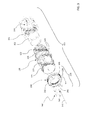
- Figure 1 shows an exploded view of a cable gland 100 for securing and retaining an optical cable 20 according to a first example of the present invention.
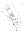
- the cable gland 100 can be inserted in a wall 50 of an optical joint closure as shown in figure 2 .
- an optical cable is first inserted and secured into a cable gland, and then the cable gland enters the optical joint closure typically through a port. This enables the operator to make the cable insertion in the gland in a more comfortable position and then attach the gland bearing the cable to the closure.
- the cable gland 100 comprises a central body 120 longitudinally extended along a direction X-X between a first end 121 and a second end 122.
- the cable gland 100 is formed of plastic material by conventional methods, for example by injection moulding.
- the first end 121 of the central body 120 is externally threaded.
- the central body 120 of the cable gland 100 comprises a cylindrical body configured to receive an optical cable 20 passing through the ends 121,122.
- the first end 121 is positioned inside the inner volume of the optical joint closure and the second end 122 is positioned outside the optical joint closure.
- the central body 120 may include one or more locking elements 123 which protrude from the surface of the body 120.
- the locking elements 123 disposed on the central body 120 have a deformable cantilever structure which can flex when depressed. After the insertion of the cable gland 100 in the optical joint closure, the locking elements 123 are secured to the wall 50 of the optical joint closure. The cable gland 100 may be removed from the optical joint closure when the cantilever structures are sufficiently depressed so as to disengage from the wall 50.
- the locking elements 123 are positioned between the first end 121 and the second end 122.
- One or two grooves may be located between the locking elements 123 and the second end 122 to receive respective O-rings 124 in order to provide environmental seal between the cable gland 100 and the optical joint closure.
- the central body 120 comprises an external threaded portion 125 located between the second end 122 and the locking elements 123.
- the external threaded portion 125 cooperates with a corresponding internal threaded portion of a first clamping nut 110 in order to radially clamp the optical cable 20 when the first clamping nut 110 is tightened on the cable gland 100.
- the second end 122 includes a plurality of spaced apart flexible fingers which can be squeezed together against the cable surface when the first clamping nut 110 is attached to the second end 122 of the central body 120.
- the first clamping nut 110 is designed to clamp a standard corrugated pipe where an optical cable 20 is fitted inside it.
- An optional internal sealing member 102 may be fitted into the second end 122 to improve the sealing capability of the overall cable gland 100 around the optical cable 20.
- the internal sealing member 102 is cylindrically and ring-shaped and it is made of rubber so that when the first clamping nut 110 is screwed on the cable gland 100, the internal sealing member 102 is squeezed improving the sealing and the retaining action on the cable 20.
- a washer 101 may be provided between the second end 122 and the first clamping element 110 (see examples of figure 3 and 5 ).
- the internal sealing member 102 may be completely filled of rubber and it comprises a plurality of holes (not shown) each for receiving a single riser/drop optical cable.
- the cable gland 100 comprises a cable securing assembly 150 attachable to the first end 121 of the cable gland 100.
- the cable securing assembly 150 is interchangeable depending on the type of the cable which passes through the cable gland as it will be described in detail herein after.
- the cable securing assembly 150 comprises a second clamping nut 130, preferably ring-shaped.
- the second clamping nut 130 comprises a lateral surface 131 internally threaded which cooperates with the first threaded end 121 of the central body 120.
- other types of fastening can be used for fastening the clamping nut 130 to the first end 121 of the cable gland (for example bayonet fittings or the like).
- the lateral surface 131 of the second clamping nut 130 extends for a length comprises between 5 mm and 15 mm, preferably 9 mm.
- the lateral surface 131 of the second clamping nut 130 ends with a tapered lateral surface 132.
- the second clamping nut 130 further comprises a first annular surface 133 connected to the tapered lateral surface 132 and which is an extension of the tapered lateral surface 132.
- the first annular surface 133 is preferably tapered.
- the second clamping nut 130 comprises a second annular surface 134 (shown in figure 1 ) connected to the first annular surface 133 and which is tapered with respect to the extension axis of the second clamping nut 130.
- the second annular surface 134 is oriented along a substantially opposite direction with respect to the first annular surface 133.
- the second annular surface 134 extends from the first annular surface 133.
- the cable securing assembly 150 comprises a cable retention group 140 cooperating with the second clamping nut 130 for retaining and securing the optical cable as better described here below.
- the cable retention group 140 comprises a cylinder 141, an internal sealing member 143 and an internal sealing disk 144 cooperating between them.
- the cylinder 141 comprises a plurality of chambers 142.
- Each chamber 142 has a circular hole for receiving a buffer tube 22 of the BLT cable 20.
- the chambers 142 may be helix-arranged with six chambers 142 circumferentially arranged and one chamber centrally arranged.
- the cylinder 141 may have different configurations with a different number of chambers 142 in order to receive other types of BLT cables.
- the internal sealing member 143 is fitted into the cylinder 141 in order to retain and secure the optical cable 20 on the cable gland 100.
- the internal sealing member 143 is preferably cylindrically-shaped and it may be made of rubber.
- the internal sealing member 143 is shaped substantially as the cylinder 141 so that the chambers 142 of the cylinder 141 are axially arranged with the chambers of the internal sealing member 143 when the BLT cable is fitted inside the cable gland 100.
- the internal sealing disk 144 is fitted into the cylinder 141 and over the internal sealing member 144.
- the edge of the second annular surface 134 pushes the internal sealing disk 144 against the internal sealing member 144 so that the latter is squeezed on the buffer tubes 22 improving the retaining action on the whole cable 20.
- this solution it is possible to seal the voids between the tubes of the BLT cable and also increase overall pull out resistance.
- the cable gland 100 is configured to receive, preferably, an MLT (or BLT) cable with a central rigid strength member 24.
- the cable gland 100 has a cable securing assembly 250 comprising a cable retention group 240 projected from a clamping nut 230 similar to the second clamping nut 130 of the first example.
- the cable retention group 240 extends along the longitudinal direction X-X from one side of the clamping nut 230.
- the cable retention group 240 is a partially extension of the lateral surface 231 of the clamping nut 230.
- the clamping nut 230 is preferably ring-shaped and comprises a lateral surface 231 internally threaded which cooperates with the first threaded end 121 of the central body 120. Even for this embodiment, other types of fastening can be used for fastening the clamping nut 230 to the first end 121 of the cable gland (for example bayonet fittings or the like).
- the lateral surface 231 of the clamping nut 230 extends for a length comprises between 5 mm and 15 mm, preferably 9 mm.
- the cable retention group 240 comprises a securing portion 241 having a cylindrical element transversally holed and configured to receive the central strength members 24 (or a central buffer tube) of a MLT optical cable passing through its hole 242.
- a grab screw 243 (shown in figure 4 ) may be inserted into the securing portion 241 in order to block from movement the central strength member 24 (or the central buffer tube) improving the retaining action of the overall MLT optical cable.
- the securing portion 241 extends along a direction Y-Y orthogonal with respect to the longitudinal direction X-X.
- the cable gland of the second example can be used for different cable types without buffer tubes (for example drop/riser cables where the fibers are loosed arranged inside a single or double layer sheath and surrounded by aramid yarns).
- the cylindrical element transversally holed is configured to receive the whole drop cable passing through the hole 242.
- the cable gland 100 is configured to receive, preferably, from one to four drop/riser optical cables with aramid yarns between the fiber units.
- the cable gland 100 has a cable securing assembly 350 comprising a cable retention group 340 projected from a clamping nut 330 similar to the clamping nut 130 of the first example.
- the cable retention group 340 extends axially along the longitudinal direction X-X from one side of the clamping nut 330.
- the clamping nut 330 is preferably ring-shaped and comprises a lateral surface 331 internally threaded which cooperates with the first threaded end 121 of the central body 120.
- the lateral surface 331 of the clamping nut 330 extends for a length comprises between 5 mm and 15 mm, preferably 9 mm.
- the cable retention group 340 is attached to the clamping nut 330 through at least two, preferably four, connection bridges 345.
- the connection bridges 345 are configured to connect the lower base 146 of the cable retention group 340 with the internal edge of the annular surface 333.
- the clamping nut 330 is made of one-piece.
- the cable retention group 340 is a separate part which may be coupled with the clamping nut 330.
- the cable retention group 340 ends with a securing portion 341 comprising a reel 342 configured to receive at least one turn of the flexible strength members of an optical cable.
- the securing portion 341 is "X" shaped in order to secure and retain at least four optical cables individually.
- the securing portion 341 may comprise two arms crossed between them so that the end of each arm is configured to support a reel 342.
- each reel 342 is shaped as an elongate mushroom with a stem 344 and an enlarged longitudinally retaining head 345.
- the stem 344 of each reels 342 extend along the orthogonal direction Y-Y forming the "X" shaped securing portion 341.
- a clip 346 configured to cooperate with the reel 342 is provided.
- Each clip 346 is configured for cooperating with a reel 343. Therefore, in case of two reels 343, there may be provided two clips 346.
- the clip 346 is configured to maintain at least one turn of the flexible strength members of an optical cable around the reel 342.
- Each of the clips 346 has a "C" cross-section.
- each clip 346 is elongate.
- each clip 346 has a length which is about the length of the reel 343.
- Each clip 346 is configured to cooperate with a reel 343 by elastically pressing towards the two parallel surfaces of the reel stem 344 for avoiding unrolling of the flexible strength members from the reel stem 344.
- the central body 120 Since when the central body 120 is fitted inside an optical joint closure, the first threaded end 121 is positioned inside the optical joint closure, it is possible, advantageously, to interchange the cable securing assembly 150 of the first example (shown in figure 1 and 2 ) with the cable securing assembly 250 of the second example (shown in figure 3 and 4 ) or with the cable securing assembly 350 of the third example (shown in figure 5 and 6 ).
- the central body 120 can be usable with different cable securing assembly 150,250,350 for retaining and securing optical cables regardless to the cable type.
- a user can change the retention elements with the central body 120 already fitted in an optical joint reducing installation times.
Landscapes
- Physics & Mathematics (AREA)
- General Physics & Mathematics (AREA)
- Optics & Photonics (AREA)
- Cable Accessories (AREA)
- Light Guides In General And Applications Therefor (AREA)
- Mechanical Coupling Of Light Guides (AREA)
Abstract
Description
- The present invention relates to the field of equipments and components for the insertion of optical cables in optical network closures, e.g. into an optical joint closure, optical network terminal or other optical junction box. In particular, the present invention relates to a cable gland comprising a separate cable securing assembly for retaining and securing an optical cable.
- Optical network closures are housing devices able to house optical components such as the splices connecting the optical fibers of one or more optical cables to respective ones of the optical fibers of another optical cable or of optical cables for final users. Optical network closures are used to protect optical splices from dirt, humidity etc. and also from stresses.
- Typically, optical cables enter into optical network closures through cable glands, which are intended to provide a safe mechanical connection of the cable to the optical network closure.
-
US 8 313 250 discloses a cable gland comprising a body having a first end and a second end, an internal sealing member shaped to be received within the second end of the body, a compression member attachable to the second end of the body and a locking elements for securing the gland when it is inserted in a joint closure. The cable gland also comprises a separate cable securing assembly with an elongated part able to fit inside the cable gland. The cable securing assembly is used to secure an optic cable by for example wrapping a length of the aramid strength members around the tie portion and tying them off. - The Applicant observes that with the solution proposed in
US 8 313 250 the separate cable securing assembly can be used for a single cable type only. As a matter of fact, different cable types can be used, differing not only in size, but also in the nature and arrangement of the cable strength member (e.g. consisting in one or more axial or peripheral rods, or made of high resistance fibers such as aramid fibers etc.), in the arrangement of optical fibers (e.g. housed in one or more tubes) etc.; in addition, some of these cable structures have also other requirements, such as provide a seal preventing access of water from the closure into the cable, and so on. - Any of these different cables and installations requires a specific gland arrangement, designed to provide the required strength member connection, sealing action, etc. This requires the installer to bring a number of different cable glands, in order to be prepared to use the one specific for each circumstance.
- In addition, in case of cable replacement, if the new cable is not identical to the original one, also the gland must be replaced. Indeed, once that the installation of a cable is made, for example by using the gland of
US8313250 , if a user wants to remove that cable and insert another cable (e.g. with a different diameter, or with a different strength member arrangement) into the cable gland for securing it on the same cable securing assembly, the elongated part of the latter inhibits the other cable to fit in the cable gland. - The Applicant has also perceived that the mechanical connection between the cable securing assembly and the cable gland does not allow an effective retaining and securing action of the optical cable since it is the cable itself which allows blocking the elongated part against the inner wall of the cable gland. If the diameter of the cable does not substantially match with the inner diameter of the cable gland, the retention group can move due to its deformability, thereby causing the risk of a detachment of the retention group from the cable gland.
- In view of the above, the Applicant has tackled the problem of providing a single cable gland usable with different cable securing assembly for retaining and securing optical cables regardless to the cable type, reducing installation times and saving moulding costs.
- The Applicant has found that it is convenient to have a cable gland in which the portion adapted to be attached to the network closure and the cable securing assembly are independent from each other and can be assembled together during installation.
- In particular, the cable gland has an end equipped with different cable securing assembly that can be attached to (with a threaded coupling for example) depending on the type of the cable which passes through the cable gland in order to retain and secure the cable on it.
- Therefore, the present invention relates to a cable gland adapted to be secured to an optical joint closure. The cable gland comprises a central body longitudinally extended between a first end and a second end and configured for receiving a cable passing through these ends, wherein when the body is partially inserted in the optical joint closure, the first end is positioned inside the inner volume of the optical joint closure and the second end is positioned outside the optical joint closure, and a cable securing assembly configured to cooperate with the first end so that the cable securing assembly is attachable to the central body in order to retain and secure said optical cable.
- Preferably, the clamping nut is ring-shaped and comprises a lateral surface at least partially internally threaded and configured to cooperate with the first end of the central body.
- Advantageously, the internal sealing member is squeezable from the clamping nut when it is attached to the central body.
- Preferably, the cable retention group projects from the clamping nut and it is completely positioned inside the inner volume of the optical joint closure.
- Advantageously, the cable retention group ends with a securing portion configured to retain and secure the cable, the securing portion being extended along an orthogonal direction with respect to the longitudinal direction.
- Preferably, the cable retention group is integrally formed with the clamping nut.
- According to an embodiment, the cable retention group is a partially extension of the lateral surface.
- Preferably, the securing portion comprises a holed finger element configured to receive the strength members passing through its hole.
- Preferably, the securing portion is attachable to the cable retention group after the strength members are passed to the hole.
- According to an embodiment, the cable retention group projects axially from the cable retention group.
- Preferably, the securing portion comprises at least a reel configured to receive at least one turn of the flexible strength members of the optical cable.
- Preferably, the cable gland comprises a clip configured to cooperate with the reel for maintaining the at least one turn of the flexible strength members around the reel.
- Preferably, the securing portion is cross-shaped in order to secure and retain at least four optical cables individually.
- The present invention will now be described in more detail hereinafter with reference to the accompanying drawings, in which some examples of the invention are shown.
-
FIG. 1 is an exploded view of a cable gland according to a first example of the present invention, -
FIG. 2 is a side view of the cable gland ofFIG. 1 in an assembled configuration when inserted in an optical joint closure, -
FIG. 3 is an exploded view of a cable gland according to a second example of the present invention, -
FIG. 4 is a side view of the cable gland ofFIG. 3 in an assembled configuration when inserted in an optical joint closure, -
FIG. 5 is an exploded view of a cable gland according to a third example of the present invention, -
FIG. 6 is a side view of the cable gland ofFIG. 5 in an assembled configuration when inserted in an optical joint closure. - For the purposes of the present description and claims an optical cable is deemed to be any optical cable comprising one or more optical fiber units, an outer sheath and, optionally, strength members.
- A fiber unit is defined as an assembly comprising one (or more) optical fiber(s) and an outer element surrounding said optical fiber(s) in order to protect the overall optical fiber(s) from damage. An optical fiber is typically constituted by a glass core, a glass cladding and a single or dual coating layer.
- The optical fiber units may be arranged in various ways.
- In particular, in the so-called "riser/drop optical cables", the fiber units are loosed arranged inside a single or double layer sheath and surrounded by aramid yarns.
- In the so-called "central loose tube cables" (briefly, CLT cables), the optical fiber units are loosely arranged within a single buffer tube, which is in turn enclosed by an external sheath.
- In the so-called "multi loose tube cables" (briefly, MLT cables), the optical fiber units are grouped in multiple bundles, the optical fiber units of each bundle being loosely arranged within a respective buffer tube. Typically, the buffer tubes may be arranged around a central strength member and stranded according to a closed or open helix (S-Z arrangement).
- Further, a so-called "blown fiber tube cables" (briefly, BLT cables), similarly to the MLT cables, comprises a plurality of buffer tubes stranded between them (or arranged around a central strength member) according to a closed or open helix (S-Z arrangement). The buffer tubes are designed to receive single fiber units (or bundles of fiber units) blown inside the buffer tubes.
- Both in CLT cables and in MTL cables, the external sheath may comprise strength members (typically made of steel or fiber reinforced resin) embedded within the sheath's thickness and placed at diametrically opposed positions. Moreover, or alternatively, the fiber units or buffer tubes may be surrounded by flexible strength members arranged radially externally of the optical fiber units. Flexible strength members may comprise aramid yarns or the like.
-
Figure 1 shows an exploded view of acable gland 100 for securing and retaining anoptical cable 20 according to a first example of the present invention. - The
cable gland 100 can be inserted in awall 50 of an optical joint closure as shown infigure 2 . - For assuring that the optical cables are secured to the optical joint closure, an optical cable is first inserted and secured into a cable gland, and then the cable gland enters the optical joint closure typically through a port. This enables the operator to make the cable insertion in the gland in a more comfortable position and then attach the gland bearing the cable to the closure.
- The
cable gland 100 comprises acentral body 120 longitudinally extended along a direction X-X between afirst end 121 and asecond end 122. Thecable gland 100 is formed of plastic material by conventional methods, for example by injection moulding. - Preferably, the
first end 121 of thecentral body 120 is externally threaded. - The
central body 120 of thecable gland 100 comprises a cylindrical body configured to receive anoptical cable 20 passing through the ends 121,122. - When the
central body 120 is partially inserted in thewall 50 of the optical joint closure, thefirst end 121 is positioned inside the inner volume of the optical joint closure and thesecond end 122 is positioned outside the optical joint closure. - The
central body 120 may include one ormore locking elements 123 which protrude from the surface of thebody 120. The lockingelements 123 disposed on thecentral body 120 have a deformable cantilever structure which can flex when depressed. After the insertion of thecable gland 100 in the optical joint closure, the lockingelements 123 are secured to thewall 50 of the optical joint closure. Thecable gland 100 may be removed from the optical joint closure when the cantilever structures are sufficiently depressed so as to disengage from thewall 50. - The locking
elements 123 are positioned between thefirst end 121 and thesecond end 122. One or two grooves may be located between the lockingelements 123 and thesecond end 122 to receive respective O-rings 124 in order to provide environmental seal between thecable gland 100 and the optical joint closure. - The
central body 120 comprises an external threadedportion 125 located between thesecond end 122 and the lockingelements 123. The external threadedportion 125 cooperates with a corresponding internal threaded portion of afirst clamping nut 110 in order to radially clamp theoptical cable 20 when thefirst clamping nut 110 is tightened on thecable gland 100. To this end, thesecond end 122 includes a plurality of spaced apart flexible fingers which can be squeezed together against the cable surface when thefirst clamping nut 110 is attached to thesecond end 122 of thecentral body 120. Further, in some cases, it is possible that thefirst clamping nut 110 is designed to clamp a standard corrugated pipe where anoptical cable 20 is fitted inside it. - An optional
internal sealing member 102 may be fitted into thesecond end 122 to improve the sealing capability of theoverall cable gland 100 around theoptical cable 20. Theinternal sealing member 102 is cylindrically and ring-shaped and it is made of rubber so that when thefirst clamping nut 110 is screwed on thecable gland 100, theinternal sealing member 102 is squeezed improving the sealing and the retaining action on thecable 20. Between thesecond end 122 and the first clamping element 110 awasher 101 may be provided (see examples offigure 3 and5 ). Optionally, for the embodiment illustrated infigure 5 and6 , theinternal sealing member 102 may be completely filled of rubber and it comprises a plurality of holes (not shown) each for receiving a single riser/drop optical cable. - Advantageously, the
cable gland 100 comprises acable securing assembly 150 attachable to thefirst end 121 of thecable gland 100. Thecable securing assembly 150 is interchangeable depending on the type of the cable which passes through the cable gland as it will be described in detail herein after. - In the example shown on
figure 1 , thecable securing assembly 150 comprises asecond clamping nut 130, preferably ring-shaped. Thesecond clamping nut 130 comprises alateral surface 131 internally threaded which cooperates with the first threadedend 121 of thecentral body 120. However, for the skilled person will be clear that other types of fastening can be used for fastening the clampingnut 130 to thefirst end 121 of the cable gland (for example bayonet fittings or the like). - The
lateral surface 131 of thesecond clamping nut 130 extends for a length comprises between 5 mm and 15 mm, preferably 9 mm. - With reference to the example shown in
figure 2 , thelateral surface 131 of thesecond clamping nut 130 ends with a taperedlateral surface 132. - The
second clamping nut 130 further comprises a firstannular surface 133 connected to the taperedlateral surface 132 and which is an extension of the taperedlateral surface 132. The firstannular surface 133 is preferably tapered. - Advantageously, the
second clamping nut 130 comprises a second annular surface 134 (shown infigure 1 ) connected to the firstannular surface 133 and which is tapered with respect to the extension axis of thesecond clamping nut 130. The secondannular surface 134 is oriented along a substantially opposite direction with respect to the firstannular surface 133. The secondannular surface 134 extends from the firstannular surface 133. - Advantageously, the
cable securing assembly 150 comprises acable retention group 140 cooperating with thesecond clamping nut 130 for retaining and securing the optical cable as better described here below. - In case the cable gland is used, for example, for a BLT cable, the
cable retention group 140 comprises acylinder 141, aninternal sealing member 143 and aninternal sealing disk 144 cooperating between them. - In particular, the
cylinder 141 comprises a plurality ofchambers 142. Eachchamber 142 has a circular hole for receiving abuffer tube 22 of theBLT cable 20. In the example shown infigure 1 , thechambers 142 may be helix-arranged with sixchambers 142 circumferentially arranged and one chamber centrally arranged. However, thecylinder 141 may have different configurations with a different number ofchambers 142 in order to receive other types of BLT cables. - Advantageously, the
internal sealing member 143 is fitted into thecylinder 141 in order to retain and secure theoptical cable 20 on thecable gland 100. In particular, theinternal sealing member 143 is preferably cylindrically-shaped and it may be made of rubber. Preferably, theinternal sealing member 143 is shaped substantially as thecylinder 141 so that thechambers 142 of thecylinder 141 are axially arranged with the chambers of theinternal sealing member 143 when the BLT cable is fitted inside thecable gland 100. - Further, the
internal sealing disk 144 is fitted into thecylinder 141 and over theinternal sealing member 144. Advantageously, when thesecond clamping nut 130 is screwed on the first threadedend 121 of thecable gland 100, the edge of the secondannular surface 134 pushes theinternal sealing disk 144 against theinternal sealing member 144 so that the latter is squeezed on thebuffer tubes 22 improving the retaining action on thewhole cable 20. Moreover, with this solution it is possible to seal the voids between the tubes of the BLT cable and also increase overall pull out resistance. - With reference to the second example shown in
figure 3 , thecable gland 100 is configured to receive, preferably, an MLT (or BLT) cable with a centralrigid strength member 24. - The
cable gland 100 has acable securing assembly 250 comprising acable retention group 240 projected from a clampingnut 230 similar to thesecond clamping nut 130 of the first example. - Preferably, the
cable retention group 240 extends along the longitudinal direction X-X from one side of the clampingnut 230. Thecable retention group 240 is a partially extension of thelateral surface 231 of the clampingnut 230. - The clamping
nut 230 is preferably ring-shaped and comprises alateral surface 231 internally threaded which cooperates with the first threadedend 121 of thecentral body 120. Even for this embodiment, other types of fastening can be used for fastening the clampingnut 230 to thefirst end 121 of the cable gland (for example bayonet fittings or the like). - The
lateral surface 231 of the clampingnut 230 extends for a length comprises between 5 mm and 15 mm, preferably 9 mm. - Advantageously, the
cable retention group 240 comprises a securingportion 241 having a cylindrical element transversally holed and configured to receive the central strength members 24 (or a central buffer tube) of a MLT optical cable passing through itshole 242. A grab screw 243 (shown infigure 4 ) may be inserted into the securingportion 241 in order to block from movement the central strength member 24 (or the central buffer tube) improving the retaining action of the overall MLT optical cable. Preferably, the securingportion 241 extends along a direction Y-Y orthogonal with respect to the longitudinal direction X-X. For the skilled person it will be clear that the cable gland of the second example can be used for different cable types without buffer tubes (for example drop/riser cables where the fibers are loosed arranged inside a single or double layer sheath and surrounded by aramid yarns). In this case, the cylindrical element transversally holed is configured to receive the whole drop cable passing through thehole 242. - With the solution here described, even when the
central body 120 is fitted inside an optical joint closure, it is possible to interchange thecable securing assembly 150 of the first example (shown infigure 1 and2 ) with thecable securing assembly 250 of the second example (shown infigure 3 and4 ) simplifying installation and saving moulding costs. - With reference to the third example shown in
figure 5 , thecable gland 100 is configured to receive, preferably, from one to four drop/riser optical cables with aramid yarns between the fiber units. - The
cable gland 100 has acable securing assembly 350 comprising acable retention group 340 projected from a clampingnut 330 similar to the clampingnut 130 of the first example. - Preferably, the
cable retention group 340 extends axially along the longitudinal direction X-X from one side of the clampingnut 330. - The clamping
nut 330 is preferably ring-shaped and comprises alateral surface 331 internally threaded which cooperates with the first threadedend 121 of thecentral body 120. - The
lateral surface 331 of the clampingnut 330 extends for a length comprises between 5 mm and 15 mm, preferably 9 mm. - The
cable retention group 340 is attached to the clampingnut 330 through at least two, preferably four, connection bridges 345. The connection bridges 345 are configured to connect the lower base 146 of thecable retention group 340 with the internal edge of theannular surface 333. - Preferably, the clamping
nut 330 is made of one-piece. Alternatively, thecable retention group 340 is a separate part which may be coupled with the clampingnut 330. For example, it may be possible to set the length of the connection bridges 345 so that their overall lengths substantially match with the diameter of theannular surface 333. Thecable retention group 340 can thus fitted inside the clampingnut 330 by friction. - Advantageously, the
cable retention group 340 ends with a securingportion 341 comprising a reel 342 configured to receive at least one turn of the flexible strength members of an optical cable. - Preferably, the securing
portion 341 is "X" shaped in order to secure and retain at least four optical cables individually. In particular, the securingportion 341 may comprise two arms crossed between them so that the end of each arm is configured to support a reel 342. Preferably, each reel 342 is shaped as an elongate mushroom with astem 344 and an enlarged longitudinally retaininghead 345. In the example offigure 5 , thestem 344 of each reels 342 extend along the orthogonal direction Y-Y forming the "X" shaped securingportion 341. - According to the example shown in
figure 6 , aclip 346 configured to cooperate with the reel 342 is provided. Eachclip 346 is configured for cooperating with areel 343. Therefore, in case of tworeels 343, there may be provided twoclips 346. Advantageously, theclip 346 is configured to maintain at least one turn of the flexible strength members of an optical cable around the reel 342. - Each of the
clips 346 has a "C" cross-section. Preferably, eachclip 346 is elongate. Preferably, eachclip 346 has a length which is about the length of thereel 343. Eachclip 346 is configured to cooperate with areel 343 by elastically pressing towards the two parallel surfaces of thereel stem 344 for avoiding unrolling of the flexible strength members from thereel stem 344. - Since when the
central body 120 is fitted inside an optical joint closure, the first threadedend 121 is positioned inside the optical joint closure, it is possible, advantageously, to interchange thecable securing assembly 150 of the first example (shown infigure 1 and2 ) with thecable securing assembly 250 of the second example (shown infigure 3 and4 ) or with thecable securing assembly 350 of the third example (shown infigure 5 and6 ). In this way, thecentral body 120 can be usable with different cable securing assembly 150,250,350 for retaining and securing optical cables regardless to the cable type. Moreover, a user can change the retention elements with thecentral body 120 already fitted in an optical joint reducing installation times.
Claims (13)
- A cable gland (100) for securing and retaining an optical cable (20), said optical cable (20) comprising optical fiber units and strength members, said cable gland (100) being partially insertable in a base (50) of an optical joint closure and comprising:- a central body (120) longitudinally extended along a longitudinal direction (X-X) between a first end (121) and a second end (122) and configured to receive said optical cable (20) passing through said ends (121,122), wherein when said central body (120) is partially inserted in said optical joint closure, said first end (121) is positioned inside the inner volume of said optical joint closure and said second end (122) is positioned outside said optical joint closure,- a cable securing assembly (150,250,350) comprising a clamping nut (130,230,330) attached to said first end (121) of said central body (120) and a cable retention group (140,240,340) cooperating with said clamping nut (130,230,330) in order to retain and secure said optical cable (20) on said cable gland (100).
- A cable gland (100) according to claim 1, wherein said clamping nut (130,230,330) is ring-shaped and comprises a lateral surface (131,231,331) at least partially internally threaded and configured to cooperate with said first end (121) of said central body (120).
- A cable gland (100) according to claim 2, comprising an internal sealing member (143) squeezable from said clamping nut (130,230,330) when said clamping nut (130,230,330) is attached to said central body (120).
- A cable gland (100) according to claim 2 or 3, wherein said cable retention group (240,340) projects from said clamping nut (130,230,330) along said longitudinal direction (X-X), said cable retention group (240,340) being completely positioned inside the inner volume of said optical joint closure.
- A cable gland (100) according to claim 4, wherein said cable retention group (240,340) ends with a securing portion (241,341) configured to retain and secure said cable (20), said securing portion (241,341) being extended along an orthogonal direction (Y-Y) with respect to said longitudinal direction (X-X).
- A cable gland (100) according to claim 4 or 5, wherein said cable retention group (240) is integrally formed with said clamping nut (130,230,330).
- A cable gland (100) according to any of claims 4-6, wherein said cable retention group (240) is a partially extension of said lateral surface (231).
- A cable gland (100) according to any of claims 5-7, wherein said securing portion (241) comprises a holed finger element configured to receive said strength members passing through its hole (242).
- A cable gland (100) according to claim 8, wherein said securing portion (241) is attachable to said cable retention group (240) after said strength members are passed to said hole (242).
- A cable gland (100) according to any of claims 4-6, wherein said cable retention group (340) projects axially from said cable retention group (330).
- A cable gland (100) according to claim 10, wherein said securing portion (341) comprises at least a reel (342) configured to receive at least one turn of said flexible strength members of said optical cable (20).
- A cable gland (100) according to claim 11, comprising a clip (346) configured to cooperate with said reel (342) for maintaining said at least one turn of said flexible strength members around said reel (342).
- A cable gland (100) according to claim 12, wherein said securing portion (341) is cross-shaped in order to secure and retain at least four optical cables (20) individually.
Priority Applications (1)
| Application Number | Priority Date | Filing Date | Title |
|---|---|---|---|
| PL15152085T PL2902827T3 (en) | 2014-02-03 | 2015-01-22 | Cable gland |
Applications Claiming Priority (1)
| Application Number | Priority Date | Filing Date | Title |
|---|---|---|---|
| ITMI20140148 | 2014-02-03 |
Publications (2)
| Publication Number | Publication Date |
|---|---|
| EP2902827A1 true EP2902827A1 (en) | 2015-08-05 |
| EP2902827B1 EP2902827B1 (en) | 2022-03-09 |
Family
ID=50391282
Family Applications (1)
| Application Number | Title | Priority Date | Filing Date |
|---|---|---|---|
| EP15152085.5A Active EP2902827B1 (en) | 2014-02-03 | 2015-01-22 | Cable gland |
Country Status (7)
| Country | Link |
|---|---|
| EP (1) | EP2902827B1 (en) |
| AR (1) | AR102313A1 (en) |
| AU (1) | AU2015200237B2 (en) |
| BR (1) | BR102015001780B1 (en) |
| DK (1) | DK2902827T3 (en) |
| ES (1) | ES2916206T3 (en) |
| PL (1) | PL2902827T3 (en) |
Cited By (8)
| Publication number | Priority date | Publication date | Assignee | Title |
|---|---|---|---|---|
| IT201800005960A1 (en) * | 2018-06-01 | 2019-12-01 | Cable gland | |
| WO2020092480A1 (en) * | 2018-10-30 | 2020-05-07 | Commscope Technologies Llc | Adapter for cable gland and cable gland unit |
| CN111123450A (en) * | 2018-10-30 | 2020-05-08 | 康普技术有限责任公司 | Adapter for cable fixing head and cable fixing head unit |
| US20210296879A1 (en) * | 2018-11-28 | 2021-09-23 | Wiska Hoppmann Gmbh | Integrally produced cable gland |
| US11287580B1 (en) | 2020-09-16 | 2022-03-29 | Berk-Tek Llc | Armored cable and connection for the same |
| CN115395307A (en) * | 2022-09-19 | 2022-11-25 | 嘉兴市盛央电气股份有限公司 | Double-layer protection sealing locking charging pile joint |
| CN115621966A (en) * | 2021-07-16 | 2023-01-17 | 黄俊杰 | Adjustable cable connector |
| CN116466456A (en) * | 2022-07-01 | 2023-07-21 | 中国船舶重工集团公司第七一三研究所 | An optical cable fixing card |
Citations (5)
| Publication number | Priority date | Publication date | Assignee | Title |
|---|---|---|---|---|
| US6052504A (en) * | 1995-04-12 | 2000-04-18 | Rxs Kabelgarnituren Gmbh | Hood sleeve |
| US20030010519A1 (en) * | 2000-02-11 | 2003-01-16 | Amandus Pieck | Wraparound seal for optical fibers |
| WO2010008718A2 (en) * | 2008-06-24 | 2010-01-21 | 3M Innovative Properties Company | Telecommunications cable inlet device |
| US8313250B2 (en) | 2008-04-09 | 2012-11-20 | 3M Innovative Properties Company | Telecommunications cable inlet device |
| US20130195414A1 (en) * | 2012-01-27 | 2013-08-01 | Hubert Blair Beamon | Fiber optic cable strain relief device and method |
-
2015
- 2015-01-20 AU AU2015200237A patent/AU2015200237B2/en active Active
- 2015-01-22 ES ES15152085T patent/ES2916206T3/en active Active
- 2015-01-22 EP EP15152085.5A patent/EP2902827B1/en active Active
- 2015-01-22 DK DK15152085.5T patent/DK2902827T3/en active
- 2015-01-22 PL PL15152085T patent/PL2902827T3/en unknown
- 2015-01-27 BR BR102015001780-4A patent/BR102015001780B1/en active IP Right Grant
- 2015-02-02 AR ARP150100296A patent/AR102313A1/en active IP Right Grant
Patent Citations (5)
| Publication number | Priority date | Publication date | Assignee | Title |
|---|---|---|---|---|
| US6052504A (en) * | 1995-04-12 | 2000-04-18 | Rxs Kabelgarnituren Gmbh | Hood sleeve |
| US20030010519A1 (en) * | 2000-02-11 | 2003-01-16 | Amandus Pieck | Wraparound seal for optical fibers |
| US8313250B2 (en) | 2008-04-09 | 2012-11-20 | 3M Innovative Properties Company | Telecommunications cable inlet device |
| WO2010008718A2 (en) * | 2008-06-24 | 2010-01-21 | 3M Innovative Properties Company | Telecommunications cable inlet device |
| US20130195414A1 (en) * | 2012-01-27 | 2013-08-01 | Hubert Blair Beamon | Fiber optic cable strain relief device and method |
Cited By (14)
| Publication number | Priority date | Publication date | Assignee | Title |
|---|---|---|---|---|
| US11502497B2 (en) | 2018-06-01 | 2022-11-15 | Prysmian S.P.A. | Cable gland |
| EP3576238A1 (en) | 2018-06-01 | 2019-12-04 | Prysmian S.p.A. | A cable gland |
| AU2019203690B2 (en) * | 2018-06-01 | 2024-09-19 | Prysmian S.P.A. | Cable gland |
| IT201800005960A1 (en) * | 2018-06-01 | 2019-12-01 | Cable gland | |
| CN111123450A (en) * | 2018-10-30 | 2020-05-08 | 康普技术有限责任公司 | Adapter for cable fixing head and cable fixing head unit |
| CN111123450B (en) * | 2018-10-30 | 2023-06-27 | 康普技术有限责任公司 | Adapter for cable fixing head and cable fixing head unit |
| WO2020092480A1 (en) * | 2018-10-30 | 2020-05-07 | Commscope Technologies Llc | Adapter for cable gland and cable gland unit |
| US20210296879A1 (en) * | 2018-11-28 | 2021-09-23 | Wiska Hoppmann Gmbh | Integrally produced cable gland |
| US11757274B2 (en) * | 2018-11-28 | 2023-09-12 | Wiska Hoppmann Gmbh | Method for producing a pre-assembled integrally produced cable gland |
| US11287580B1 (en) | 2020-09-16 | 2022-03-29 | Berk-Tek Llc | Armored cable and connection for the same |
| US11808990B2 (en) | 2020-09-16 | 2023-11-07 | Berk-Tek Llc | Armored cable and connection for the same |
| CN115621966A (en) * | 2021-07-16 | 2023-01-17 | 黄俊杰 | Adjustable cable connector |
| CN116466456A (en) * | 2022-07-01 | 2023-07-21 | 中国船舶重工集团公司第七一三研究所 | An optical cable fixing card |
| CN115395307A (en) * | 2022-09-19 | 2022-11-25 | 嘉兴市盛央电气股份有限公司 | Double-layer protection sealing locking charging pile joint |
Also Published As
| Publication number | Publication date |
|---|---|
| PL2902827T3 (en) | 2022-06-27 |
| AU2015200237A1 (en) | 2015-08-20 |
| AU2015200237B2 (en) | 2019-01-17 |
| AR102313A1 (en) | 2017-02-22 |
| BR102015001780A2 (en) | 2015-09-22 |
| EP2902827B1 (en) | 2022-03-09 |
| BR102015001780B1 (en) | 2021-10-05 |
| ES2916206T3 (en) | 2022-06-29 |
| DK2902827T3 (en) | 2022-06-07 |
Similar Documents
| Publication | Publication Date | Title |
|---|---|---|
| EP2902827B1 (en) | Cable gland | |
| EP2950125B1 (en) | Torsion resistant cable gland | |
| EP2277241B1 (en) | Telecommunications cable inlet device | |
| US9395509B2 (en) | Fiber cable fan-out assembly and method | |
| JP5106235B2 (en) | Reinforced connector system including transducer | |
| US7668426B2 (en) | Fiber optic cable assembly with integrated compressing member for strain relief | |
| RU2164357C2 (en) | Device for distributing optical fiber joints | |
| US20120230636A1 (en) | Connector device and method for producing a furcated fibre optic cable | |
| WO2016206594A1 (en) | Optical fiber connector assembly | |
| US20140226935A1 (en) | Self engaging port plug | |
| US5862291A (en) | Cable routing device | |
| RU2013104008A (en) | OPTICAL CABLE SPACING BOX CONTAINING AN AUXILIARY DEVICE FOR FILLING GAPES AND ENSURING WATERPROOFNESS | |
| US9846290B1 (en) | Tool system for routing an optical fiber or cable through walls at customer premises | |
| KR102790799B1 (en) | Cable gland with internal dam | |
| US9459427B2 (en) | Fiber optic fan-out/break-out kit closure/housing | |
| US20100046904A1 (en) | Adapter for sleeves with elastomer cable seals and method for introducing a fiber-optic cable into a sleeve | |
| KR101671850B1 (en) | Optical cable | |
| EP2608336A1 (en) | Sealing unit | |
| KR101603452B1 (en) | Optical drop cable locking device | |
| WO2011089218A1 (en) | Pipe connector | |
| KR20010036362A (en) | An optical fiber cable inlet device | |
| RU115512U1 (en) | DEVICE FOR INPUT INTO THE CLUTCH OF THE OPTICAL CABLE EMBEDDED IN THE GROWTHWAY | |
| ITMI980370U1 (en) | CABLE GLANDS FOR CABLES WITHIN PROTECTIVE TUBES IN ELECTRICAL SYSTEMS |
Legal Events
| Date | Code | Title | Description |
|---|---|---|---|
| PUAI | Public reference made under article 153(3) epc to a published international application that has entered the european phase |
Free format text: ORIGINAL CODE: 0009012 |
|
| 17P | Request for examination filed |
Effective date: 20150122 |
|
| AK | Designated contracting states |
Kind code of ref document: A1 Designated state(s): AL AT BE BG CH CY CZ DE DK EE ES FI FR GB GR HR HU IE IS IT LI LT LU LV MC MK MT NL NO PL PT RO RS SE SI SK SM TR |
|
| AX | Request for extension of the european patent |
Extension state: BA ME |
|
| 17P | Request for examination filed |
Effective date: 20160205 |
|
| RBV | Designated contracting states (corrected) |
Designated state(s): AL AT BE BG CH CY CZ DE DK EE ES FI FR GB GR HR HU IE IS IT LI LT LU LV MC MK MT NL NO PL PT RO RS SE SI SK SM TR |
|
| RAP1 | Party data changed (applicant data changed or rights of an application transferred) |
Owner name: PRYSMIAN S.P.A. |
|
| STAA | Information on the status of an ep patent application or granted ep patent |
Free format text: STATUS: EXAMINATION IS IN PROGRESS |
|
| 17Q | First examination report despatched |
Effective date: 20190911 |
|
| GRAP | Despatch of communication of intention to grant a patent |
Free format text: ORIGINAL CODE: EPIDOSNIGR1 |
|
| STAA | Information on the status of an ep patent application or granted ep patent |
Free format text: STATUS: GRANT OF PATENT IS INTENDED |
|
| INTG | Intention to grant announced |
Effective date: 20210901 |
|
| RIN1 | Information on inventor provided before grant (corrected) |
Inventor name: KERRY, MATT |
|
| GRAS | Grant fee paid |
Free format text: ORIGINAL CODE: EPIDOSNIGR3 |
|
| GRAA | (expected) grant |
Free format text: ORIGINAL CODE: 0009210 |
|
| STAA | Information on the status of an ep patent application or granted ep patent |
Free format text: STATUS: THE PATENT HAS BEEN GRANTED |
|
| AK | Designated contracting states |
Kind code of ref document: B1 Designated state(s): AL AT BE BG CH CY CZ DE DK EE ES FI FR GB GR HR HU IE IS IT LI LT LU LV MC MK MT NL NO PL PT RO RS SE SI SK SM TR |
|
| REG | Reference to a national code |
Ref country code: GB Ref legal event code: FG4D |
|
| REG | Reference to a national code |
Ref country code: CH Ref legal event code: EP Ref country code: AT Ref legal event code: REF Ref document number: 1474643 Country of ref document: AT Kind code of ref document: T Effective date: 20220315 |
|
| REG | Reference to a national code |
Ref country code: DE Ref legal event code: R096 Ref document number: 602015077358 Country of ref document: DE |
|
| REG | Reference to a national code |
Ref country code: IE Ref legal event code: FG4D |
|
| REG | Reference to a national code |
Ref country code: RO Ref legal event code: EPE |
|
| REG | Reference to a national code |
Ref country code: FI Ref legal event code: FGE |
|
| REG | Reference to a national code |
Ref country code: DK Ref legal event code: T3 Effective date: 20220603 |
|
| REG | Reference to a national code |
Ref country code: NL Ref legal event code: FP |
|
| REG | Reference to a national code |
Ref country code: LT Ref legal event code: MG9D |
|
| REG | Reference to a national code |
Ref country code: ES Ref legal event code: FG2A Ref document number: 2916206 Country of ref document: ES Kind code of ref document: T3 Effective date: 20220629 |
|
| REG | Reference to a national code |
Ref country code: NO Ref legal event code: T2 Effective date: 20220309 |
|
| PG25 | Lapsed in a contracting state [announced via postgrant information from national office to epo] |
Ref country code: SE Free format text: LAPSE BECAUSE OF FAILURE TO SUBMIT A TRANSLATION OF THE DESCRIPTION OR TO PAY THE FEE WITHIN THE PRESCRIBED TIME-LIMIT Effective date: 20220309 Ref country code: RS Free format text: LAPSE BECAUSE OF FAILURE TO SUBMIT A TRANSLATION OF THE DESCRIPTION OR TO PAY THE FEE WITHIN THE PRESCRIBED TIME-LIMIT Effective date: 20220309 Ref country code: LT Free format text: LAPSE BECAUSE OF FAILURE TO SUBMIT A TRANSLATION OF THE DESCRIPTION OR TO PAY THE FEE WITHIN THE PRESCRIBED TIME-LIMIT Effective date: 20220309 Ref country code: HR Free format text: LAPSE BECAUSE OF FAILURE TO SUBMIT A TRANSLATION OF THE DESCRIPTION OR TO PAY THE FEE WITHIN THE PRESCRIBED TIME-LIMIT Effective date: 20220309 Ref country code: BG Free format text: LAPSE BECAUSE OF FAILURE TO SUBMIT A TRANSLATION OF THE DESCRIPTION OR TO PAY THE FEE WITHIN THE PRESCRIBED TIME-LIMIT Effective date: 20220609 |
|
| REG | Reference to a national code |
Ref country code: AT Ref legal event code: MK05 Ref document number: 1474643 Country of ref document: AT Kind code of ref document: T Effective date: 20220309 |
|
| PG25 | Lapsed in a contracting state [announced via postgrant information from national office to epo] |
Ref country code: LV Free format text: LAPSE BECAUSE OF FAILURE TO SUBMIT A TRANSLATION OF THE DESCRIPTION OR TO PAY THE FEE WITHIN THE PRESCRIBED TIME-LIMIT Effective date: 20220309 Ref country code: GR Free format text: LAPSE BECAUSE OF FAILURE TO SUBMIT A TRANSLATION OF THE DESCRIPTION OR TO PAY THE FEE WITHIN THE PRESCRIBED TIME-LIMIT Effective date: 20220610 |
|
| PG25 | Lapsed in a contracting state [announced via postgrant information from national office to epo] |
Ref country code: SM Free format text: LAPSE BECAUSE OF FAILURE TO SUBMIT A TRANSLATION OF THE DESCRIPTION OR TO PAY THE FEE WITHIN THE PRESCRIBED TIME-LIMIT Effective date: 20220309 Ref country code: SK Free format text: LAPSE BECAUSE OF FAILURE TO SUBMIT A TRANSLATION OF THE DESCRIPTION OR TO PAY THE FEE WITHIN THE PRESCRIBED TIME-LIMIT Effective date: 20220309 Ref country code: PT Free format text: LAPSE BECAUSE OF FAILURE TO SUBMIT A TRANSLATION OF THE DESCRIPTION OR TO PAY THE FEE WITHIN THE PRESCRIBED TIME-LIMIT Effective date: 20220711 Ref country code: EE Free format text: LAPSE BECAUSE OF FAILURE TO SUBMIT A TRANSLATION OF THE DESCRIPTION OR TO PAY THE FEE WITHIN THE PRESCRIBED TIME-LIMIT Effective date: 20220309 Ref country code: CZ Free format text: LAPSE BECAUSE OF FAILURE TO SUBMIT A TRANSLATION OF THE DESCRIPTION OR TO PAY THE FEE WITHIN THE PRESCRIBED TIME-LIMIT Effective date: 20220309 Ref country code: AT Free format text: LAPSE BECAUSE OF FAILURE TO SUBMIT A TRANSLATION OF THE DESCRIPTION OR TO PAY THE FEE WITHIN THE PRESCRIBED TIME-LIMIT Effective date: 20220309 |
|
| PG25 | Lapsed in a contracting state [announced via postgrant information from national office to epo] |
Ref country code: IS Free format text: LAPSE BECAUSE OF FAILURE TO SUBMIT A TRANSLATION OF THE DESCRIPTION OR TO PAY THE FEE WITHIN THE PRESCRIBED TIME-LIMIT Effective date: 20220709 Ref country code: AL Free format text: LAPSE BECAUSE OF FAILURE TO SUBMIT A TRANSLATION OF THE DESCRIPTION OR TO PAY THE FEE WITHIN THE PRESCRIBED TIME-LIMIT Effective date: 20220309 |
|
| REG | Reference to a national code |
Ref country code: DE Ref legal event code: R097 Ref document number: 602015077358 Country of ref document: DE |
|
| PLBE | No opposition filed within time limit |
Free format text: ORIGINAL CODE: 0009261 |
|
| STAA | Information on the status of an ep patent application or granted ep patent |
Free format text: STATUS: NO OPPOSITION FILED WITHIN TIME LIMIT |
|
| 26N | No opposition filed |
Effective date: 20221212 |
|
| PG25 | Lapsed in a contracting state [announced via postgrant information from national office to epo] |
Ref country code: SI Free format text: LAPSE BECAUSE OF FAILURE TO SUBMIT A TRANSLATION OF THE DESCRIPTION OR TO PAY THE FEE WITHIN THE PRESCRIBED TIME-LIMIT Effective date: 20220309 |
|
| REG | Reference to a national code |
Ref country code: CH Ref legal event code: PL |
|
| PG25 | Lapsed in a contracting state [announced via postgrant information from national office to epo] |
Ref country code: LU Free format text: LAPSE BECAUSE OF NON-PAYMENT OF DUE FEES Effective date: 20230122 |
|
| REG | Reference to a national code |
Ref country code: BE Ref legal event code: MM Effective date: 20230131 |
|
| PG25 | Lapsed in a contracting state [announced via postgrant information from national office to epo] |
Ref country code: LI Free format text: LAPSE BECAUSE OF NON-PAYMENT OF DUE FEES Effective date: 20230131 Ref country code: CH Free format text: LAPSE BECAUSE OF NON-PAYMENT OF DUE FEES Effective date: 20230131 |
|
| PG25 | Lapsed in a contracting state [announced via postgrant information from national office to epo] |
Ref country code: BE Free format text: LAPSE BECAUSE OF NON-PAYMENT OF DUE FEES Effective date: 20230131 |
|
| PG25 | Lapsed in a contracting state [announced via postgrant information from national office to epo] |
Ref country code: MC Free format text: LAPSE BECAUSE OF FAILURE TO SUBMIT A TRANSLATION OF THE DESCRIPTION OR TO PAY THE FEE WITHIN THE PRESCRIBED TIME-LIMIT Effective date: 20220309 |
|
| PG25 | Lapsed in a contracting state [announced via postgrant information from national office to epo] |
Ref country code: MC Free format text: LAPSE BECAUSE OF FAILURE TO SUBMIT A TRANSLATION OF THE DESCRIPTION OR TO PAY THE FEE WITHIN THE PRESCRIBED TIME-LIMIT Effective date: 20220309 |
|
| PG25 | Lapsed in a contracting state [announced via postgrant information from national office to epo] |
Ref country code: CY Free format text: LAPSE BECAUSE OF FAILURE TO SUBMIT A TRANSLATION OF THE DESCRIPTION OR TO PAY THE FEE WITHIN THE PRESCRIBED TIME-LIMIT; INVALID AB INITIO Effective date: 20150122 |
|
| PG25 | Lapsed in a contracting state [announced via postgrant information from national office to epo] |
Ref country code: HU Free format text: LAPSE BECAUSE OF FAILURE TO SUBMIT A TRANSLATION OF THE DESCRIPTION OR TO PAY THE FEE WITHIN THE PRESCRIBED TIME-LIMIT; INVALID AB INITIO Effective date: 20150122 |
|
| PG25 | Lapsed in a contracting state [announced via postgrant information from national office to epo] |
Ref country code: TR Free format text: LAPSE BECAUSE OF FAILURE TO SUBMIT A TRANSLATION OF THE DESCRIPTION OR TO PAY THE FEE WITHIN THE PRESCRIBED TIME-LIMIT Effective date: 20220309 |
|
| PGFP | Annual fee paid to national office [announced via postgrant information from national office to epo] |
Ref country code: NL Payment date: 20260126 Year of fee payment: 12 |
|
| PGFP | Annual fee paid to national office [announced via postgrant information from national office to epo] |
Ref country code: GB Payment date: 20260127 Year of fee payment: 12 |
|
| PGFP | Annual fee paid to national office [announced via postgrant information from national office to epo] |
Ref country code: ES Payment date: 20260202 Year of fee payment: 12 |
|
| PGFP | Annual fee paid to national office [announced via postgrant information from national office to epo] |
Ref country code: DE Payment date: 20260128 Year of fee payment: 12 Ref country code: NO Payment date: 20260128 Year of fee payment: 12 Ref country code: DK Payment date: 20260126 Year of fee payment: 12 Ref country code: IE Payment date: 20260127 Year of fee payment: 12 |
|
| PGFP | Annual fee paid to national office [announced via postgrant information from national office to epo] |
Ref country code: FI Payment date: 20260126 Year of fee payment: 12 Ref country code: RO Payment date: 20260113 Year of fee payment: 12 Ref country code: IT Payment date: 20260121 Year of fee payment: 12 |
|
| PGFP | Annual fee paid to national office [announced via postgrant information from national office to epo] |
Ref country code: FR Payment date: 20260126 Year of fee payment: 12 |
|
| PGFP | Annual fee paid to national office [announced via postgrant information from national office to epo] |
Ref country code: PL Payment date: 20260107 Year of fee payment: 12 |