US9459427B2 - Fiber optic fan-out/break-out kit closure/housing - Google Patents
Fiber optic fan-out/break-out kit closure/housing Download PDFInfo
- Publication number
- US9459427B2 US9459427B2 US14/994,123 US201614994123A US9459427B2 US 9459427 B2 US9459427 B2 US 9459427B2 US 201614994123 A US201614994123 A US 201614994123A US 9459427 B2 US9459427 B2 US 9459427B2
- Authority
- US
- United States
- Prior art keywords
- male
- fiber optic
- shell
- housing
- break
- Prior art date
- Legal status (The legal status is an assumption and is not a legal conclusion. Google has not performed a legal analysis and makes no representation as to the accuracy of the status listed.)
- Active
Links
Images


Classifications
-
- G—PHYSICS
- G02—OPTICS
- G02B—OPTICAL ELEMENTS, SYSTEMS OR APPARATUS
- G02B6/00—Light guides; Structural details of arrangements comprising light guides and other optical elements, e.g. couplings
- G02B6/44—Mechanical structures for providing tensile strength and external protection for fibres, e.g. optical transmission cables
- G02B6/4439—Auxiliary devices
- G02B6/4471—Terminating devices ; Cable clamps
- G02B6/4477—Terminating devices ; Cable clamps with means for strain-relieving to interior strengths element
Definitions
- Embodiments of the disclosure relate generally to fiber optic cable industry. Embodiments relate more particularly to a fiber optic fan-out/break-out kit Closure/Housing that is assembled in a particular, pre-set manner.
- An electrical cable is made of two or more wires that are bonded, twisted or braided together to form a single assembly. Typically, the ends of the electrical cable are connected to two devices thereby enabling the transfer of electrical signals from one device to another.
- an optic fiber cable is an electrical cable containing one or more optical fibers that are used to carry light.
- Fiber cable termination is the addition of connectors to each optical fiber in a cable. Typically, the fibers need to have connectors fitted before they are attached to other equipment.
- Two common solutions for fiber cable termination are pigtails and fan-out kits (breakout kits). Specifically, a fan-out kit is a set of empty jackets designed to protect fragile tight-buffered strands of fiber from a cable. This allows the individual fibers to be terminated without splicing and without needing a protective enclosure (such as a splicebox).
- the existing optic fiber cables lack enhanced design and a more robust solution to easily fit in the customers' equipment.
- the principal object of the embodiments herein is to provide a pre-configured fiber optic fan-out/break-out kit Closure/Housing for 8, 12, 24, or a custom number of fiber stranded fiber optic (round or oval) applications with custom or standard lengths.
- the fiber optic fan-out/break-out kit Closure/Housing provides an enhanced design with a more robust solution to fit easily into a customer's equipment.
- Another object of the embodiments herein is to allow the fiber optic cable manufacture to separate the 250-micron fibers and route them individually through 2 millimeter or 3 millimeter furcation tube.
- Yet another object of the embodiments herein is to protect the delicate 250-micron fibers from being damaged during termination process of all industry standard connectors.
- the fiber optic fan-out/break-out Closure/Housing comprises of a female shell, a male shell, an insert piece and an insert tool. The insert tool is temporarily attached to the insert piece thereby screwing the insert piece into the male shell.
- An example of a method for implementing a fiber optic fan-out/break-out kit Closure/Housing includes fastening a male insert into a male cavity of a shell using a male insert tool to secure the fiber optic cable from protruding forward or backwards after assembling. Further, the method includes assembling a female and male shell/cover.
- FIG. 1 illustrates an exploded perspective view of a fiber optic fan-out/break-out kit
- FIG. 2 illustrates an exploded view of the male shell/cover of the fiber optic fan-out/break-out kit Closure/Housing of FIG. 1 , according to the embodiments as disclosed herein;
- FIG. 3 illustrates an exploded view of the male insert of the fiber optic fan-out/break-out kit Closure/Housing of FIG. 1 , according to the embodiments as disclosed herein;
- FIG. 4 illustrates an exploded view of the female shell/cover of the fiber optic fan-out/break-out kit Closure/Housing of FIG. 1 , according to the embodiments as disclosed herein;
- FIG. 5 illustrates an exploded perspective view of the fiber optic fan-out/break-out kit Closure/Housing of FIG. 1 in an assembled state, according to the embodiments as disclosed herein;
- FIG. 6 illustrates an exploded view of an insert tool , according to the embodiments as disclosed herein.
- FIG. 7 is a flow chart describing a method for using the fiber optic fan-out/break-out Closure/Housing, according to the embodiments as disclosed herein.
- the present invention provides a fiber optic fan-out/break-out kit Closure/Housing that provides several enhanced elements for securing the fiber optic fan-out kit, ultimately preventing incorrect assembly.
- the present invention consists of two housings, one female, one male, an insert piece and an insert tool.
- the fiber optic fan-out/break-out kit Closure/Housing is made of plastic. It will be appreciated to those skilled in the art that, any other suitable and/or similar material may be used.
- the fiber optic fan-out kit is a complete housing/closure protecting the fiber optic strands associated with the fiber optic cable.
- male housing and “male shell/cover” may be interchangeable used throughout the description herein.
- female housing and “female shell/cover” may be interchangeable used throughout the description herein.
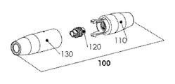
- FIG. 1 illustrates an exploded perspective view of a fiber optic fan-out/break-out kit Closure/Housing 100 , according to the embodiments as disclosed herein.
- the fiber optic fan-out/break-out kit Closure/Housing 100 includes a male shell/cover 110 , a male insert 120 and a female shell/cover 130 .
- the male shell/cover 110 attaches to the female shell/cover 130 with attached fingers and end clips.
- the female shell/cover 130 attaches to the male housing with attached slots and pockets. Further, the male insert 120 screws into the male housing to hold the fiber optic cable in place securely.
- FIG. 2 illustrates an exploded view of the male shell/cover 110 of the fiber optic fan-out/break-out kit Closure/Housing 100 of FIG. 1 , according to the embodiments as disclosed herein.
- the fiber optic fan-out/break-out kit Closure/Housing 100 includes two male clips 111 , two male keys 112 , and threaded cavity for the male insert 113 .
- FIG. 3 illustrates an exploded view of the male insert 120 of the fiber optic fan-out/break-out kit Closure/Housing 100 of FIG. 1 , according to the embodiments as disclosed herein.
- the fiber optic fan-out/break-out kit Closure/Housing 100 includes threads 122 for connection of the male shell/cover 110 of FIG. 1 and added material for ease of handling 123 .
- a notch 121 is also shown.
- FIG. 4 illustrates an exploded view of the female shell/cover 130 of the fiber optic fan-out/break-out kit Closure/Housing 100 of FIG. 1 , according to the embodiments as disclosed herein.
- the fiber optic fan-out/break-out kit Closure/Housing 100 includes two female slots 131 and two female slots 132 for male clips.
- FIG. 5 illustrates an exploded perspective view of a male insert tool 140 for the fiber optic fan-out/break-out kit closure/housing 100 of FIG. 1 , according to the embodiments as disclosed herein.
- the male insert tool 140 includes a female slot 141 to attach to the male insert 120 male notch 121 . Further, the male insert tool 140 also includes a handle with indention 142 to assist the assembler/user with screwing in the male insert 120 into the male housing cavity 113 .
- FIG. 6 illustrates an exploded perspective view of the fiber optic fan-out/break-out kit Closure/Housing 100 of FIG. 1 in an assembled state 150 , according to the embodiments as disclosed herein.
- the fiber optic fan-out/break-out kit Closure/Housing 100 includes a fiber optic furcation tube 151 , a female shell/cover 152 , a male shell/cover 153 and a fiber optic cable 154 .
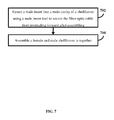
- FIG. 7 is a flow chart describing a method for using the fiber optic fan-out/break-out Closure/Housing, according to the embodiments as disclosed herein.
- the flow chart begins at step 702 .
- the present invention is used as a closure/housing to protect fiber strands from exposure and damage.
- a male insert is fastened into a male cavity of a shell/cover using a male insert tool to secure the fiber optic cable from protruding forward after assembling.
- a female and male shell/cover is assembled together.
- the method ends at step 704 .
- the fiber optic fan-out/break-out kit Closure/Housing is beneficial for several reasons as listed below:
Landscapes
- Physics & Mathematics (AREA)
- General Physics & Mathematics (AREA)
- Optics & Photonics (AREA)
- Light Guides In General And Applications Therefor (AREA)
- Structures Of Non-Positive Displacement Pumps (AREA)
- Insertion, Bundling And Securing Of Wires For Electric Apparatuses (AREA)
Abstract
A fiber optic fan-out/break-out kit Closure/Housing for protecting fiber optic strands associated with the fiber optic cable. The fiber optic fan-out/break-out Closure/Housing comprises of a female shell, a male shell, an insert piece and an insert tool. The insert tool is temporarily attached to the insert piece thereby screwing the insert piece into the male shell.
Description
Embodiments of the disclosure relate generally to fiber optic cable industry. Embodiments relate more particularly to a fiber optic fan-out/break-out kit Closure/Housing that is assembled in a particular, pre-set manner.
An electrical cable is made of two or more wires that are bonded, twisted or braided together to form a single assembly. Typically, the ends of the electrical cable are connected to two devices thereby enabling the transfer of electrical signals from one device to another.
Further, an optic fiber cable is an electrical cable containing one or more optical fibers that are used to carry light. Fiber cable termination is the addition of connectors to each optical fiber in a cable. Typically, the fibers need to have connectors fitted before they are attached to other equipment. Two common solutions for fiber cable termination are pigtails and fan-out kits (breakout kits). Specifically, a fan-out kit is a set of empty jackets designed to protect fragile tight-buffered strands of fiber from a cable. This allows the individual fibers to be terminated without splicing and without needing a protective enclosure (such as a splicebox).
However, the existing optic fiber cables lack enhanced design and a more robust solution to easily fit in the customers' equipment.
In the light of the above discussion, there appears to be a need for providing a better fiber optic fan-out kit design with a more robust solution.
The principal object of the embodiments herein is to provide a pre-configured fiber optic fan-out/break-out kit Closure/Housing for 8, 12, 24, or a custom number of fiber stranded fiber optic (round or oval) applications with custom or standard lengths. Specifically, the fiber optic fan-out/break-out kit Closure/Housing provides an enhanced design with a more robust solution to fit easily into a customer's equipment.
Another object of the embodiments herein is to allow the fiber optic cable manufacture to separate the 250-micron fibers and route them individually through 2 millimeter or 3 millimeter furcation tube.
Yet another object of the embodiments herein is to protect the delicate 250-micron fibers from being damaged during termination process of all industry standard connectors.
The above-mentioned needs are met by a fiber optic fan-out/break-out kit Closure/Housing and a method for implementing the fiber optic fan-out/break-out kit Closure/Housing.
A fiber optic fan-out/break-out kit Closure/Housing for protecting fiber optic strands associated with the fiber optic cable. The fiber optic fan-out/break-out Closure/Housing comprises of a female shell, a male shell, an insert piece and an insert tool. The insert tool is temporarily attached to the insert piece thereby screwing the insert piece into the male shell.
An example of a method for implementing a fiber optic fan-out/break-out kit Closure/Housing includes fastening a male insert into a male cavity of a shell using a male insert tool to secure the fiber optic cable from protruding forward or backwards after assembling. Further, the method includes assembling a female and male shell/cover.
These and other aspects of the embodiments herein will be better appreciated and understood when considered in conjunction with the following description and the accompanying drawings. It should be understood, however, that the following descriptions, while indicating preferred embodiments and numerous specific details thereof, are given by way of illustration and not of limitation. Many changes and modifications may be made within the scope of the embodiments herein without departing from the spirit thereof, and the embodiments herein include all such modifications.
In the accompanying figures, similar reference numerals may refer to identical or functionally similar elements. These reference numerals are used in the detailed description to illustrate various embodiments and to explain various aspects and advantages of the present disclosure.
Closure/Housing, according to the embodiments as disclosed herein;
The above-mentioned needs are met by a fiber optic fan-out/break-out kit Closure/Housing that is assembled in a particular, pre-set manner. The following detailed description is intended to provide example implementations to one of ordinary skill in the art, and is not intended to limit the invention to the explicit disclosure, as one or ordinary skill in the art will understand that variations can be substituted that are within the scope of the invention as described.
In the following detailed description, for purposes of explanation, numerous specific details are set forth in order to provide a thorough understanding of the disclosed embodiments. It will be apparent, however, that one or more embodiments may be practiced without these specific details. In other instances, well-known structures and devices are schematically shown in order to simplify the drawings.
The present invention provides a fiber optic fan-out/break-out kit Closure/Housing that provides several enhanced elements for securing the fiber optic fan-out kit, ultimately preventing incorrect assembly. Specifically, the present invention consists of two housings, one female, one male, an insert piece and an insert tool. The fiber optic fan-out/break-out kit Closure/Housing is made of plastic. It will be appreciated to those skilled in the art that, any other suitable and/or similar material may be used. Further, the fiber optic fan-out kit is a complete housing/closure protecting the fiber optic strands associated with the fiber optic cable.
It should be appreciated to those skilled in the art that, “male housing” and “male shell/cover” may be interchangeable used throughout the description herein. Similarly, “female housing” and “female shell/cover” may be interchangeable used throughout the description herein.
The male shell/cover 110 attaches to the female shell/cover 130 with attached fingers and end clips. The female shell/cover 130 attaches to the male housing with attached slots and pockets. Further, the male insert 120 screws into the male housing to hold the fiber optic cable in place securely.
It will be appreciated to those skilled in the art that 150 is only for illustration purposes. The use of the fiber optic fan-out/break-out kit Closure/Housing 100 may be used for any configuration at any point in time.
Specifically, the present invention is used as a closure/housing to protect fiber strands from exposure and damage.
At step 702, a male insert is fastened into a male cavity of a shell/cover using a male insert tool to secure the fiber optic cable from protruding forward after assembling.
At step 704, a female and male shell/cover is assembled together.
The method ends at step 704.
The fiber optic fan-out/break-out kit Closure/Housing is beneficial for several reasons as listed below:
-
- 1. Provides an enhanced design thereby making it end-user friendly.
- 2. Provides a snap-fit design.
- 3. Provides a smaller outer diameter.
- 4. Allows effective and efficient manufacturing process.
- 5. Provides a robust solution.
- 6. Minimizes unnecessary assembly steps thereby making the manufacturing process simple.
Accordingly, the disclosure of the present invention is intended to be illustrative, but not limiting, of the scope of the invention, which is set forth in the following claims.
Claims (7)
1. A fiber optic fan-out/break-out kit Closure/ Housing for protecting fiber optic strands associated with the fiber optic cable, the fiber optic fan-out/break-out kit Closure/ Housing comprising:
a female shell and male shell; and
a male insert piece having screw threads for connecting to the male shell, and having added material for ease of handling, and further having a male notch for accommodating an insert tool;
wherein the insert tool is temporarily attached to the male notch of the male insert piece for screwing the male insert piece into the male shell.
2. The fiber optic fan-out/break-out kit Closure/ Housing of claim 1 wherein the female shell further comprises:
two female key slots; and
two female clip slots at the opening of the mouth of the female shell.
3. The fiber optic fan-out/break-out kit Closure/ Housing of claim 1 wherein the male shell attaches to the female shell with attached fingers and end clips.
4. The fiber optic fan-out/break-out kit Closure/ Housing of claim 1 wherein the female shell attaches to the male shell with attached slots and pockets.
5. The fiber optic fan-out/break-out kit Closure/ Housing of claim 1 wherein the male insert screws into the male shell to secure the fiber optic cable from protruding forward after assembly.
6. The fiber optic fan-out/break-out kit Closure/ Housing of claim 1 wherein the male shell further comprises:
two male keys and two male clips at the top of the mouth to secure the female shell to the male shell when assembled together.
7. A method for implementing a fiber optic fan-out/break-out kit Closure/Housing, the method comprising:
fastening a male insert into a male cavity of a shell using a male insert tool to secure the fiber optic cable from protruding forward after assembling; and
assembling a female and male shell/cover.
Priority Applications (1)
| Application Number | Priority Date | Filing Date | Title |
|---|---|---|---|
| US14/994,123 US9459427B2 (en) | 2015-01-12 | 2016-01-12 | Fiber optic fan-out/break-out kit closure/housing |
Applications Claiming Priority (2)
| Application Number | Priority Date | Filing Date | Title |
|---|---|---|---|
| US201562102566P | 2015-01-12 | 2015-01-12 | |
| US14/994,123 US9459427B2 (en) | 2015-01-12 | 2016-01-12 | Fiber optic fan-out/break-out kit closure/housing |
Publications (2)
| Publication Number | Publication Date |
|---|---|
| US20160202438A1 US20160202438A1 (en) | 2016-07-14 |
| US9459427B2 true US9459427B2 (en) | 2016-10-04 |
Family
ID=56367421
Family Applications (1)
| Application Number | Title | Priority Date | Filing Date |
|---|---|---|---|
| US14/994,123 Active US9459427B2 (en) | 2015-01-12 | 2016-01-12 | Fiber optic fan-out/break-out kit closure/housing |
Country Status (4)
| Country | Link |
|---|---|
| US (1) | US9459427B2 (en) |
| JP (1) | JP2018502337A (en) |
| CN (1) | CN107407786B (en) |
| WO (1) | WO2016115180A1 (en) |
Cited By (1)
| Publication number | Priority date | Publication date | Assignee | Title |
|---|---|---|---|---|
| US11243367B2 (en) | 2018-08-03 | 2022-02-08 | Afl Telecommunications Llc | Multiple cable size fiber optic transition assemblies |
Families Citing this family (3)
| Publication number | Priority date | Publication date | Assignee | Title |
|---|---|---|---|---|
| US10018783B2 (en) * | 2016-12-05 | 2018-07-10 | Mellanox Technologies, Ltd. | Fan-out joint for fiberoptic cables |
| EP3612881A4 (en) | 2017-04-17 | 2021-01-13 | Commscope Technologies LLC | Fiber routing systems |
| CN111801614B (en) | 2018-03-30 | 2022-10-18 | 康普技术有限责任公司 | Cable fanout apparatus and method thereof |
Citations (9)
| Publication number | Priority date | Publication date | Assignee | Title |
|---|---|---|---|---|
| US4824204A (en) * | 1986-05-30 | 1989-04-25 | Pafford Thomas L | Fiber optic connector that joins multiple, but at least one, fiber optic cables to a dual diametered fiber optic cable and a multiple position clamp to juxtapose a plurality of the said fiber optic connecter |
| US4883336A (en) * | 1989-02-17 | 1989-11-28 | Conseil National De Recherches Du Canada | Method and leadthrough system for laying out optical fibres across an aperture of a container shell |
| US20050276551A1 (en) * | 2004-06-15 | 2005-12-15 | Troy Brown | Fiber optic furcation tube and method |
| US20060088250A1 (en) * | 2004-10-25 | 2006-04-27 | Panduit Corp. | Collet assembly with ribbon fiber holder |
| US20080138026A1 (en) * | 2006-12-08 | 2008-06-12 | Yow Charles A | Furcation tubing and fanout furcation kit |
| US20120230636A1 (en) * | 2009-07-20 | 2012-09-13 | Nicholas Blockley | Connector device and method for producing a furcated fibre optic cable |
| US20130028568A1 (en) * | 2011-07-29 | 2013-01-31 | Hubert Blair Beamon | Fiber optic cables seal and/or strain relief members, and related assemblies and methods |
| US20130170801A1 (en) * | 2012-01-03 | 2013-07-04 | Sehf-Korea Co., Ltd. | Branching device for hybrid fan-out cable |
| US20130183012A1 (en) * | 2012-01-13 | 2013-07-18 | Alma Delia Cabanne Lopez | Fan-out kit for a furcation system |
Family Cites Families (14)
| Publication number | Priority date | Publication date | Assignee | Title |
|---|---|---|---|---|
| US4119302A (en) * | 1977-04-11 | 1978-10-10 | Moroco Philip A | Object supports |
| US4795229A (en) * | 1987-05-07 | 1989-01-03 | Amp Incorporated | Strain relief assembly for optical fiber connector |
| US5224187A (en) * | 1992-04-29 | 1993-06-29 | Scientific-Atlanta, Inc. | Fiber optic cable connectors providing strain relief |
| JP2821971B2 (en) * | 1993-03-25 | 1998-11-05 | 矢崎総業株式会社 | Insert fixing jig for DFP casting machine |
| US5471555A (en) * | 1994-11-21 | 1995-11-28 | Sumitomo Electric Lightwave Corp. | Fiber optic ribbon break-out device with enhanced strain relief |
| WO2000008498A1 (en) * | 1998-08-03 | 2000-02-17 | Daewoo Telecom Ltd. | Device for branching multi-fiber optical cable and method for branching cable using the device |
| US6434315B1 (en) * | 2000-06-23 | 2002-08-13 | Molex Incorporated | Fiber optic connector |
| US6816663B2 (en) * | 2003-04-07 | 2004-11-09 | Fitel Usa Corp. | Unitary fan-out device for optical ribbon cables |
| US7738759B2 (en) * | 2007-03-16 | 2010-06-15 | 3M Innovative Properties Company | Optical fiber cable inlet device |
| EP2354824A1 (en) * | 2010-01-29 | 2011-08-10 | CCS Technology Inc. | Hybrid connector |
| CN202995082U (en) * | 2011-06-27 | 2013-06-12 | 3M创新有限公司 | Optical fiber connector for terminating optical fibers |
| WO2014022261A1 (en) * | 2012-08-03 | 2014-02-06 | Tyco Electronics Corporation | Optical fiber fan-out device |
| CN202904070U (en) * | 2012-10-29 | 2013-04-24 | 罗森伯格亚太电子有限公司 | Multi-core optical fiber connector |
| CN202948164U (en) * | 2012-11-26 | 2013-05-22 | 罗森伯格亚太电子有限公司 | Outdoor multicore optical fiber connecting device |
-
2016
- 2016-01-12 JP JP2017555453A patent/JP2018502337A/en active Pending
- 2016-01-12 CN CN201680014549.3A patent/CN107407786B/en active Active
- 2016-01-12 WO PCT/US2016/013115 patent/WO2016115180A1/en active Application Filing
- 2016-01-12 US US14/994,123 patent/US9459427B2/en active Active
Patent Citations (10)
| Publication number | Priority date | Publication date | Assignee | Title |
|---|---|---|---|---|
| US4824204A (en) * | 1986-05-30 | 1989-04-25 | Pafford Thomas L | Fiber optic connector that joins multiple, but at least one, fiber optic cables to a dual diametered fiber optic cable and a multiple position clamp to juxtapose a plurality of the said fiber optic connecter |
| US4883336A (en) * | 1989-02-17 | 1989-11-28 | Conseil National De Recherches Du Canada | Method and leadthrough system for laying out optical fibres across an aperture of a container shell |
| US20050276551A1 (en) * | 2004-06-15 | 2005-12-15 | Troy Brown | Fiber optic furcation tube and method |
| US20060088250A1 (en) * | 2004-10-25 | 2006-04-27 | Panduit Corp. | Collet assembly with ribbon fiber holder |
| US7121732B2 (en) * | 2004-10-25 | 2006-10-17 | Panduit Corp. | Collet assembly with ribbon fiber holder |
| US20080138026A1 (en) * | 2006-12-08 | 2008-06-12 | Yow Charles A | Furcation tubing and fanout furcation kit |
| US20120230636A1 (en) * | 2009-07-20 | 2012-09-13 | Nicholas Blockley | Connector device and method for producing a furcated fibre optic cable |
| US20130028568A1 (en) * | 2011-07-29 | 2013-01-31 | Hubert Blair Beamon | Fiber optic cables seal and/or strain relief members, and related assemblies and methods |
| US20130170801A1 (en) * | 2012-01-03 | 2013-07-04 | Sehf-Korea Co., Ltd. | Branching device for hybrid fan-out cable |
| US20130183012A1 (en) * | 2012-01-13 | 2013-07-18 | Alma Delia Cabanne Lopez | Fan-out kit for a furcation system |
Cited By (1)
| Publication number | Priority date | Publication date | Assignee | Title |
|---|---|---|---|---|
| US11243367B2 (en) | 2018-08-03 | 2022-02-08 | Afl Telecommunications Llc | Multiple cable size fiber optic transition assemblies |
Also Published As
| Publication number | Publication date |
|---|---|
| CN107407786A (en) | 2017-11-28 |
| US20160202438A1 (en) | 2016-07-14 |
| JP2018502337A (en) | 2018-01-25 |
| CN107407786B (en) | 2020-06-26 |
| WO2016115180A1 (en) | 2016-07-21 |
Similar Documents
| Publication | Publication Date | Title |
|---|---|---|
| US11543613B2 (en) | Fiber optic cable with flexible conduit | |
| EP2277241B1 (en) | Telecommunications cable inlet device | |
| US9459427B2 (en) | Fiber optic fan-out/break-out kit closure/housing | |
| US8814446B2 (en) | Splice protection device for optical splices | |
| US9529173B2 (en) | Optical fiber furcation assembly and method | |
| TW201535002A (en) | Integrated fiber optic cable fan-out connector | |
| US10656360B2 (en) | Epoxy transitions for optical fiber modules | |
| US8270799B2 (en) | Telecommunications cable inlet device | |
| EP2950125A1 (en) | Torsion resistant cable gland | |
| PT2772778E (en) | Fiber optic plug | |
| WO2016206594A1 (en) | Optical fiber connector assembly | |
| EP2902827B1 (en) | Cable gland | |
| US11520115B2 (en) | Cable sealing device | |
| JP6603344B2 (en) | Branch member | |
| EP2159612B1 (en) | Connector for optical fiber cable | |
| JP6877432B2 (en) | Optical connector plug | |
| KR20110009064U (en) | Turnout protection tube hold ribbon multi fiber | |
| EP2784559B1 (en) | Enclosure with cable seal | |
| JP2008096847A (en) | Terminal processing structure of pseudocord for optical fiber, holder for the pseudocord, and simple terminal processing structure for optical fiber connection | |
| JP2005345840A (en) | Boot for mt connector |
Legal Events
| Date | Code | Title | Description |
|---|---|---|---|
| STCF | Information on status: patent grant |
Free format text: PATENTED CASE |
|
| FEPP | Fee payment procedure |
Free format text: SURCHARGE FOR LATE PAYMENT, MICRO ENTITY (ORIGINAL EVENT CODE: M3554); ENTITY STATUS OF PATENT OWNER: MICROENTITY |
|
| MAFP | Maintenance fee payment |
Free format text: PAYMENT OF MAINTENANCE FEE, 4TH YEAR, MICRO ENTITY (ORIGINAL EVENT CODE: M3551); ENTITY STATUS OF PATENT OWNER: MICROENTITY Year of fee payment: 4 |