EP2902801A1 - Wireless sensor device - Google Patents
Wireless sensor device Download PDFInfo
- Publication number
- EP2902801A1 EP2902801A1 EP13842032.8A EP13842032A EP2902801A1 EP 2902801 A1 EP2902801 A1 EP 2902801A1 EP 13842032 A EP13842032 A EP 13842032A EP 2902801 A1 EP2902801 A1 EP 2902801A1
- Authority
- EP
- European Patent Office
- Prior art keywords
- transmission
- signal
- circuit
- antenna
- output terminal
- Prior art date
- Legal status (The legal status is an assumption and is not a legal conclusion. Google has not performed a legal analysis and makes no representation as to the accuracy of the status listed.)
- Withdrawn
Links
- 230000005540 biological transmission Effects 0.000 claims abstract description 205
- 238000001514 detection method Methods 0.000 claims abstract description 65
- 238000000034 method Methods 0.000 claims abstract description 22
- 230000035945 sensitivity Effects 0.000 abstract description 30
- 230000006866 deterioration Effects 0.000 abstract description 6
- 238000006243 chemical reaction Methods 0.000 description 7
- 230000007704 transition Effects 0.000 description 6
- 238000013459 approach Methods 0.000 description 5
- 238000010586 diagram Methods 0.000 description 5
- 230000010363 phase shift Effects 0.000 description 4
- 230000029058 respiratory gaseous exchange Effects 0.000 description 4
- 230000010355 oscillation Effects 0.000 description 2
- 230000002238 attenuated effect Effects 0.000 description 1
- 230000003247 decreasing effect Effects 0.000 description 1
- 230000003111 delayed effect Effects 0.000 description 1
- 230000000694 effects Effects 0.000 description 1
- 230000007274 generation of a signal involved in cell-cell signaling Effects 0.000 description 1
- 230000010287 polarization Effects 0.000 description 1
- 230000001902 propagating effect Effects 0.000 description 1
- 230000005855 radiation Effects 0.000 description 1
- 238000005070 sampling Methods 0.000 description 1
Images

Classifications
-
- H—ELECTRICITY
- H04—ELECTRIC COMMUNICATION TECHNIQUE
- H04W—WIRELESS COMMUNICATION NETWORKS
- H04W24/00—Supervisory, monitoring or testing arrangements
- H04W24/10—Scheduling measurement reports ; Arrangements for measurement reports
-
- G—PHYSICS
- G01—MEASURING; TESTING
- G01S—RADIO DIRECTION-FINDING; RADIO NAVIGATION; DETERMINING DISTANCE OR VELOCITY BY USE OF RADIO WAVES; LOCATING OR PRESENCE-DETECTING BY USE OF THE REFLECTION OR RERADIATION OF RADIO WAVES; ANALOGOUS ARRANGEMENTS USING OTHER WAVES
- G01S13/00—Systems using the reflection or reradiation of radio waves, e.g. radar systems; Analogous systems using reflection or reradiation of waves whose nature or wavelength is irrelevant or unspecified
- G01S13/02—Systems using reflection of radio waves, e.g. primary radar systems; Analogous systems
- G01S13/50—Systems of measurement based on relative movement of target
- G01S13/52—Discriminating between fixed and moving objects or between objects moving at different speeds
- G01S13/56—Discriminating between fixed and moving objects or between objects moving at different speeds for presence detection
-
- G—PHYSICS
- G01—MEASURING; TESTING
- G01S—RADIO DIRECTION-FINDING; RADIO NAVIGATION; DETERMINING DISTANCE OR VELOCITY BY USE OF RADIO WAVES; LOCATING OR PRESENCE-DETECTING BY USE OF THE REFLECTION OR RERADIATION OF RADIO WAVES; ANALOGOUS ARRANGEMENTS USING OTHER WAVES
- G01S7/00—Details of systems according to groups G01S13/00, G01S15/00, G01S17/00
- G01S7/02—Details of systems according to groups G01S13/00, G01S15/00, G01S17/00 of systems according to group G01S13/00
- G01S7/03—Details of HF subsystems specially adapted therefor, e.g. common to transmitter and receiver
-
- G—PHYSICS
- G01—MEASURING; TESTING
- G01S—RADIO DIRECTION-FINDING; RADIO NAVIGATION; DETERMINING DISTANCE OR VELOCITY BY USE OF RADIO WAVES; LOCATING OR PRESENCE-DETECTING BY USE OF THE REFLECTION OR RERADIATION OF RADIO WAVES; ANALOGOUS ARRANGEMENTS USING OTHER WAVES
- G01S7/00—Details of systems according to groups G01S13/00, G01S15/00, G01S17/00
- G01S7/02—Details of systems according to groups G01S13/00, G01S15/00, G01S17/00 of systems according to group G01S13/00
- G01S7/28—Details of pulse systems
-
- H—ELECTRICITY
- H04—ELECTRIC COMMUNICATION TECHNIQUE
- H04W—WIRELESS COMMUNICATION NETWORKS
- H04W4/00—Services specially adapted for wireless communication networks; Facilities therefor
- H04W4/70—Services for machine-to-machine communication [M2M] or machine type communication [MTC]
-
- H—ELECTRICITY
- H04—ELECTRIC COMMUNICATION TECHNIQUE
- H04W—WIRELESS COMMUNICATION NETWORKS
- H04W64/00—Locating users or terminals or network equipment for network management purposes, e.g. mobility management
- H04W64/006—Locating users or terminals or network equipment for network management purposes, e.g. mobility management with additional information processing, e.g. for direction or speed determination
Definitions
- the present invention relates to a wireless sensor device and in particular relates to a wireless sensor device capable of detecting a minute variation with high sensitivity.
- sensors which are each capable of detecting vital signs such as a heart rate and breathing in a non-contact manner and less stressful on a detection target.
- a wireless sensor device 900 includes a transmitting and receiving antenna ANT constructed by integrating first and second polarized antennas, the polarization planes of the radiation waves of which are orthogonal to each other, a first mixer circuit 914a that is connected to the first polarized antenna and into which a first reception signal received by the first polarized antenna is input, a second mixer circuit 914b that is connected to the second polarized antenna and into which a second reception signal received by the second polarized antenna is input, a signal generation circuit 911 that generates a pulse signal power-fed into the first and second polarized antennas and supplied to the first and second mixer circuits 914a and 914b, and a differential amplifier circuit 915.
- This differential amplifier circuit 915 differentially amplifies a mixed output into which the first mixer circuit 914a mixes the first reception signal and the pulse signal and a mixed output into which the second mixer circuit 914b mixes the second reception signal and the pulse signal.
- the RF oscillation circuit 911 generates the pulse signal to be power-fed into the transmitting and receiving antenna ANT, and a distributor 912 distributes and individually sends the pulse signal received from the RF oscillation circuit 911 to each of power feeding points 913a and 913b of the transmitting and receiving antenna ANT and sends, to each of the mixer circuits 914a and 914b, part of the pulse signal sent to each of the power feeding points 913a and 913b of this transmitting and receiving antenna ANT.
- the motion of the target object O is detected from a combined signal Vt of a transmission signal Vo and a reflected wave Vr. If being expressed using a mathematical expression, a relationship between the combined signal Vt and the transmission signal Vo and reflected wave Vr is expressed as the following (Expression 1).
- Vt 2 Vo 2 + Vr 2 - 2 ⁇ Vo ⁇ Vr ⁇ cos ⁇
- ⁇ is the change-in-phase angle (phase difference) of the reflected wave Vr with respect to the transmission signal Vo.
- Vt ⁇ ⁇ Vo 2 + Vr 2 - 2 ⁇ Vo ⁇ Vr ⁇ cos ⁇
- detection sensitivity varies remarkably based on a distance between the wireless sensor device and the detection target.
- a wireless sensor device includes an antenna configured to radiate a transmission signal and receive a reflected signal caused by the transmission signal reflected by a detection target, a transmission circuit including an output terminal, connected to the antenna, and configured to generate the transmission signal, a detector circuit in which part of the transmission signal and the reflected signal received by the antenna are input thereinto and detected while the transmission signal is transmitted from the transmission circuit, the detector circuit being connected to the output terminal of the transmission circuit, a signal processing circuit connected to the detector circuit and configured to process a signal output from the detector circuit, and a control circuit connected to the transmission circuit and configured to control the transmission circuit, wherein, between the antenna and the output terminal, a plurality of transmission lines whose line lengths are different from one another and switching means for switching between the plural transmission lines and connecting the antenna and the output terminal to each other are provided, and differences in line length between the plural transmission lines are less than one-fourth of a wavelength of the transmission signal.
- the plural transmission lines are two transmission lines and the line lengths of the two transmission lines are different from each other by one-eighth of the wavelength of the transmission signal.
- the plural transmission lines whose line lengths are different from one another and the switching means for switching between the plural transmission lines and connecting the antenna and the output terminal to each other are provided, and differences in line length between the plural transmission lines are set to less than one-fourth of the wavelength of the transmission signal.
- the phase difference of the reflected wave with respect to the transmission output approaches the null point where sensitivity is reduced and a detection output is reduced, it is possible to change the phase difference by selecting and switching between the transmission lines whose line lengths are different from each other and it is possible to detect a minute variation with high sensitivity by avoiding the deterioration of sensitivity for sensing the motion of the detection target.
- control circuit controls so as to switch between the plural transmission lines and performs switching by selecting a transmission line where a signal output from the signal processing circuit becomes a maximum, it is possible to detect the motion of the detection target in a state where the sensitivity is higher.
- the wireless sensor device 100 radiates a transmission signal toward a detection target and detects the reflected signal thereof, thereby sensing the detection target.
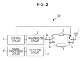
- Fig. 2 is a block diagram illustrating the configuration of the wireless sensor device 100.
- the wireless sensor device 100 includes an antenna 1, a transmission circuit 2 equipped with an output terminal 2a, a detector circuit 3, a signal processing circuit 4, a control circuit 5, a first transmission line 6, a second transmission line 7, a first switch 8, and a second switch 9.
- the wireless sensor device 100 includes a power supply circuit not illustrated, and electric power necessary for the operations of individual units in the wireless sensor device 100 is supplied thereto.
- the antenna 1 is connected to the second switch 9, and one end of each of the first transmission line 6 and the second transmission line 7 is connected to the second switch 9 serving as switching means so that it is possible to select and connect one of the first transmission line 6 and the second transmission line 7 to the antenna 1.
- the first switch 8 is connected to another end of each of the first transmission line 6 and the second transmission line 7, the first switch 8 serving as switching means for selecting and connecting one of the first transmission line 6 and the second transmission line 7 to the output terminal 2a of the transmission circuit 2, and the first switch 8 is connected to the output terminal 2a of the transmission circuit 2.
- the transmission circuit 2 performs a transmission operation for generating the transmission signal and outputting the transmission signal to the output terminal 2a.
- the detector circuit 3 is connected to the output terminal 2a of the transmission circuit 2. In addition, during the transmission operation of the transmission circuit 2, part of the transmission signal output from the output terminal 2a and the reflected signal received by the antenna 1 are input into the detector circuit 3 and part of the input transmission signal and the reflected signal received by the antenna 1 are detected.
- the signal processing circuit 4 is connected to the detector circuit 3, performs signal processing for a detection output signal output from the detector circuit 3, and outputs the result thereof to the control circuit 5.
- the control circuit 5 is connected to the transmission circuit 2, the signal processing circuit 4, the first switch 8, and the second switch 9.
- the control circuit 5 controls the operation state of the transmission circuit 2, acquires an output signal from the signal processing circuit 4, detects a body motion associated with the breathing of the detection target, the motion of a body surface associated with a heart rate thereof, and so forth, and performs determination of the presence or absence of detection and so forth.
- control circuit 5 outputs a control signal for controlling the first switch 8 and the second switch 9, selecting one of the first transmission line 6 and the second transmission line 7, and connecting the antenna 1 and the output terminal 2a to each other.
- the first transmission line 6 is a transmission line that has characteristic impedance roughly equal to the output impedance of the transmission circuit 2 and the impedance of the antenna 1 at the frequency of the transmission signal generated by the transmission circuit 2 and whose line length is Le.
- the second transmission line 7 is a transmission line that has characteristic impedance roughly equal to the output impedance of the transmission circuit 2 and the impedance of the antenna 1 at the frequency of the transmission signal generated by the transmission circuit 2 and whose line length is Le+ ⁇ /8 that is longer than the line length, Le, of the first transmission line 6 by one-eighth of the wavelength of the transmission signal if one wavelength of the transmission signal is ⁇ .
- the length of the transmission line is expressed using the wavelength or the phase shift angle of the transmission signal propagating through the transmission line.
- the above-mentioned wavelength of the transmission signal indicates a wavelength on the transmission line and one-eighth of the wavelength corresponds to a length where the phase shift delay of ⁇ /4 (rad) occurs in terms of a phase shift angle.
- the control circuit 5 controls the first switch 8 and the second switch 9 and selects the first transmission line 6, the transmission signal output from the output terminal 2a of the transmission circuit 2 is radiated from the antenna 1 through the first switch 8, the first transmission line 6, and the second switch 9.
- the transmission signal radiated from the antenna 1 is reflected by the detection target and received as the reflected signal by the antenna 1.
- the reflected signal received by the antenna 1 returns to the output terminal 2a through the second switch 9, the first transmission line 6, and the first switch 8, and part of the transmission signal and the reflected signal are input into the detector circuit 3 and detected.
- the length of a path from the output terminal 2a to the antenna is expressed by the line length, Le, of the first transmission line 6.
- a distance from the antenna 1 to the detection target is Lx
- the length, L1 of a path where the transmission signal is output from the output terminal 2a, part of the transmission signal radiated by the antenna 1 is reflected by the detection target, and that reflected signal is received by the antenna 1 and returns to the output terminal 2a is expressed as (Expression 5).
- the control circuit 5 controls the first switch 8 and the second switch 9 and selects the second transmission line 7
- the transmission signal output from the output terminal 2a of the transmission circuit 2 is radiated from the antenna 1 through the first switch 8, the second transmission line 7, and the second switch 9.
- the reflected signal received by the antenna 1 returns to the output terminal 2a through the second switch 9, the second transmission line 7, and the first switch 8, and part of the transmission signal and the reflected signal are input into the detector circuit 3 and detected.
- the length of a path from the output terminal 2a to the antenna is expressed by the line length, Le+ ⁇ /8, of the second transmission line 7.
- a difference, ⁇ L, between the length of the path in a case where the first transmission line 6 is selected and the length of the path in a case where the second transmission line 7 is selected becomes (Expression 7), based on (Expression 5) and (Expression 6).
- the length of the path in a case where the first transmission line 6 is selected and the length of the path in a case where the second transmission line 7 is selected are different from each other by a difference corresponding to one-fourth of the wavelength of the transmission signal. Therefore, in accordance with the amount of this difference between the lengths, in a case where the second transmission line 7 is selected, a length leading to the arrival of the reflected wave at the detector circuit 3 is lengthened by ⁇ /4 compared with a case where the first transmission line 6 is selected, and the phase of the reflected wave is delayed by ⁇ /2 (rad).
- the detection output detected by the detector circuit 3 is input into the signal processing circuit 4.
- the signal processing circuit 4 amplifies a change in amplitude of the detection signal and outputs, to the control circuit 5, Analog-to-Digital Convertion signal (AD conversion signal) where the amplified detection signal is converted from an analog signal to a digital signal.
- AD conversion signal Analog-to-Digital Convertion signal
- the control circuit 5 controls the signal processing circuit 4, acquires the AD conversion signal, detects a body motion associated with breathing, the motion of a body surface associated with a heart rate, and so forth, received from the detection target, and performs determination of the presence or absence of detection and so forth.
- the control circuit 5 determines that a distance to the detection target fluctuates and approaches the null point where an output is remarkably reduced, controls the first switch 8 and the second switch 9 so as to select a transmission line different from a currently selected transmission line, and controls so as to prevent sensitivity from being reduced.
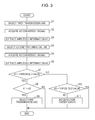
- Fig. 3 is a flowchart diagram illustrating the control operation of the wireless sensor device 100, and an operation is periodically repeated and performed using a timer function and so forth embedded in the control circuit 5.
- control circuit 5 controls the first switch 8 and the second switch 9 and selects the first transmission line 6.
- control circuit 5 controls the signal processing circuit 4 and acquires the AD conversion signal from the signal processing circuit 4.
- amplitude information corresponding to a change in amplitude of the detection signal caused by the motion of the detection target is extracted from the AD conversion signal, acquired in the procedure S2, and held as first amplitude information A1 indicating detection sensitivity at the time of selecting the first transmission line 6.
- control circuit 5 controls the first switch 8 and the second switch 9 and selects the second transmission line 7.
- control circuit 5 controls the signal processing circuit 4 and acquires the AD conversion signal from the signal processing circuit 4.
- amplitude information corresponding to a change in amplitude of the detection signal caused by the motion of the detection target is extracted from the AD conversion signal, acquired in the procedure S5, and held as second amplitude information A2 indicating detection sensitivity at the time of selecting the second transmission line 7.
- a procedure S7 comparison between the held first amplitude information A1 and a threshold value is performed, the threshold value being used for determining that a distance between the wireless sensor device 100 and the detection target approaches the null point and the sensitivity is reduced, and the control operation makes a transition to a procedure S8 in a case where the first amplitude information A1 is greater than the threshold value, and makes a transition to a procedure S10 in a case where the first amplitude information A1 is less than or equal to the threshold value.
- the control operation makes a transition to a procedure S9.
- the second amplitude information A2 is larger, since the second transmission line 7 is selected at this time point, the control processing is terminated without change. Since, in this case, the second amplitude information A2 at the time of selecting the second transmission line 7 is larger than the first amplitude information A1 while the first amplitude information A1 at the time of selecting the first transmission line 6 is greater than or equal to the threshold value, it is possible to detect the motion of the detection target with higher sensitivity.
- the control circuit 5 controls the first switch 8 and the second switch 9, selects the first transmission line 6, and terminates the control processing. Since, in this case, the first amplitude information A1 at the time of selecting the first transmission line 6 is greater than or equal to the threshold value and the second amplitude information A2 at the time of selecting the second transmission line 7 is less than or equal to the first amplitude information A1, the first transmission line is finally selected and it is possible to detect the motion of the detection target with high sensitivity.
- the control processing makes a transition to the procedure S10
- the procedure S10 comparison between the held second amplitude information A2 and a threshold value is performed, the threshold value being used for determining that a distance between the wireless sensor device 100 and the detection target approaches the null point and the sensitivity is reduced, and the second transmission line 7 is selected at this time point in a case where the second amplitude information A2 is greater than the threshold value. Therefore, the control processing is terminated without change.
- the control processing makes a transition to a procedure S11.
- the first transmission line 6 and the second transmission line 7 whose line lengths are different from each other and the first switch 8 and the second switch 9 that switch between the first transmission line 6 and the second transmission line 7 and connect the antenna 1 and the output terminal 2a to each other are provided between the antenna 1 and the output terminal 2a, and a difference in line length between the first transmission line 6 and the second transmission line 7 is set to less than one-fourth of the wavelength of the transmission signal.
- the phase difference of the reflected wave with respect to the transmission output approaches the null point where sensitivity is reduced, and the detection output is reduced, it is possible to change the phase difference by selecting and switching between the transmission lines whose line lengths are different from each other and it is possible to detect a minute variation with high sensitivity by avoiding the deterioration of sensitivity for sensing the motion of the detection target.
- a phase difference between the transmission signal output to the output terminal 2a of the transmission circuit 2 and the reflected signal, which is caused by the transmission signal reflected by the detection target and returns to the output terminal 2a, varies by ⁇ /2 (rad) by switching between the transmission lines, and it is possible to operate in a state in which sensitivity is good, by reliably avoiding the null point where sensitivity is remarkably reduced.
- control circuit 5 controls so as to switch between the plural transmission lines and performs switching by selecting a transmission line where a signal output from the signal processing circuit 4 becomes a maximum, it is possible to detect the motion of the detection target in a state where the sensitivity is higher.
- the wireless sensor device of an embodiment according to the present invention is specifically described as above, the present invention is not limited to the above-mentioned embodiment and may be variously altered and implemented without departing from the scope thereof.
- the present invention may be modified and implemented, for example, as follows, and these embodiments belong to the technical scope of the present invention.
Landscapes
- Engineering & Computer Science (AREA)
- Computer Networks & Wireless Communication (AREA)
- Radar, Positioning & Navigation (AREA)
- Remote Sensing (AREA)
- Physics & Mathematics (AREA)
- General Physics & Mathematics (AREA)
- Signal Processing (AREA)
- Radar Systems Or Details Thereof (AREA)
- Geophysics And Detection Of Objects (AREA)
Abstract
Description
- The present invention relates to a wireless sensor device and in particular relates to a wireless sensor device capable of detecting a minute variation with high sensitivity.
- In the past, there have been proposed a sensor that measures a distance to a detection target using a radio wave, a sensor that detects the presence or absence or the approximation of a detection target, and so forth.
- In recent years, from a heightened awareness of health, there have been desired sensors which are each capable of detecting vital signs such as a heart rate and breathing in a non-contact manner and less stressful on a detection target.
- As a wireless sensor device that detects a detection target in a non-contact manner, there has been known a wireless sensor device described in PTL 1.
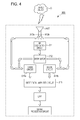
- In a wireless sensor device 1 described in PTL 1, as illustrated in
Fig. 4 , awireless sensor device 900 includes a transmitting and receiving antenna ANT constructed by integrating first and second polarized antennas, the polarization planes of the radiation waves of which are orthogonal to each other, a first mixer circuit 914a that is connected to the first polarized antenna and into which a first reception signal received by the first polarized antenna is input, asecond mixer circuit 914b that is connected to the second polarized antenna and into which a second reception signal received by the second polarized antenna is input, asignal generation circuit 911 that generates a pulse signal power-fed into the first and second polarized antennas and supplied to the first andsecond mixer circuits 914a and 914b, and adifferential amplifier circuit 915. Thisdifferential amplifier circuit 915 differentially amplifies a mixed output into which the first mixer circuit 914a mixes the first reception signal and the pulse signal and a mixed output into which thesecond mixer circuit 914b mixes the second reception signal and the pulse signal. - The
RF oscillation circuit 911 generates the pulse signal to be power-fed into the transmitting and receiving antenna ANT, and adistributor 912 distributes and individually sends the pulse signal received from theRF oscillation circuit 911 to each ofpower feeding points mixer circuits 914a and 914b, part of the pulse signal sent to each of thepower feeding points - There has been disclosed the technology of the wireless sensor device where a radio wave radiated from the transmitting and receiving antenna ANT is reflected by a target object O, a reception signal obtained by receiving this reflected wave using the transmitting and receiving antenna ANT and part of the first pulse signal to be power-fed into the
power feeding point 913a of the transmitting and receiving antenna ANT through thedistributor 912 are input into the mixer circuit 914a, part of the second pulse signal to be power-fed into thepower feeding point 913b of the transmitting and receiving antenna ANT is input into themixer circuit 914b, and it is possible to detect the motion of the target object O by detecting a change in phase difference of the reception signal based on the motion of the target object O. - In the above-mentioned wireless sensor device of the related art, the motion of the target object O is detected from a combined signal Vt of a transmission signal Vo and a reflected wave Vr. If being expressed using a mathematical expression, a relationship between the combined signal Vt and the transmission signal Vo and reflected wave Vr is expressed as the following (Expression 1).

- In this regard, however, θ is the change-in-phase angle (phase difference) of the reflected wave Vr with respect to the transmission signal Vo.
- Accordingly, the combined signal Vt is expressed by the following (Expression 2).

- Since the phase of the reflected wave Vr with respect to the transmission output Vo changes, a change in the combined signal with respect to a change in the phase is obtained by differentiating (Expression 2) with respect to the phase shift angle θ and expressed by the following (Expression 3).

- Since being attenuated based on the propagation loss of a round trip with respect to a distance to the detection target and the reflectance of the detection target, the reflected wave Vr is far smaller than the transmission output Vo and satisfies Vo»Vr. Therefore, (Expression 3) may be approximated by (Expression 4).

- PTL 1: Japanese Unexamined Patent Application
- Even in the wireless sensor device of the related art, in a case where the motion of the detection target is large and the phase of the reflected signal caused by the transmission signal, radiated toward the detection target and reflected by the detection target, greatly changes for the transmission signal, it is possible to detect the motion of the detection target without difficulty.
- However, in a case where the motion of the detection target is small and a change in phase of the reflected signal reflected by the detection target is small for the transmission signal, examples of which including a body motion associated with breathing and the motion of a body surface associated with a heart rate, detection sensitivity varies remarkably based on a distance between the wireless sensor device and the detection target.
- In a case where a phase difference between the transmission signal and the reflected signal becomes θ≈π/2 radian (abbreviated as rad hereinafter) or θ≈3π/2 (rad) based on a distance between the wireless sensor device and the detection target, the maximum value Vr of a change in the combined signal may be obtained from (Expression 4). However, three has been a problem that since, in a case of the value of θ≈0 (rad) or θ≈π (rad), the output of the combined signal becomes 0, the output thereof is significantly decreased and becomes a null (Null) point.
- An object of the present invention is to provide a wireless sensor device capable of solving the above-mentioned problem and detecting a minute variation with high sensitivity by avoiding the deterioration of sensitivity for sensing the motion of a detection target.
- In order to solve this problem, a wireless sensor device according to Claim 1 includes an antenna configured to radiate a transmission signal and receive a reflected signal caused by the transmission signal reflected by a detection target, a transmission circuit including an output terminal, connected to the antenna, and configured to generate the transmission signal, a detector circuit in which part of the transmission signal and the reflected signal received by the antenna are input thereinto and detected while the transmission signal is transmitted from the transmission circuit, the detector circuit being connected to the output terminal of the transmission circuit, a signal processing circuit connected to the detector circuit and configured to process a signal output from the detector circuit, and a control circuit connected to the transmission circuit and configured to control the transmission circuit, wherein, between the antenna and the output terminal, a plurality of transmission lines whose line lengths are different from one another and switching means for switching between the plural transmission lines and connecting the antenna and the output terminal to each other are provided, and differences in line length between the plural transmission lines are less than one-fourth of a wavelength of the transmission signal.
- In the wireless sensor device according to
Claim 2, the plural transmission lines are two transmission lines and the line lengths of the two transmission lines are different from each other by one-eighth of the wavelength of the transmission signal. - In the wireless sensor device according to Claim 3, the control circuit controls so as to switch between the plural transmission lines and performs switching by selecting a transmission line where a signal output from the signal processing circuit becomes a maximum.
- According to the invention of Claim 1, between the antenna and the output terminal, the plural transmission lines whose line lengths are different from one another and the switching means for switching between the plural transmission lines and connecting the antenna and the output terminal to each other are provided, and differences in line length between the plural transmission lines are set to less than one-fourth of the wavelength of the transmission signal. Therefore, in a case where, owing to the variation of a distance to the detection target or the like, the phase difference of the reflected wave with respect to the transmission output approaches the null point where sensitivity is reduced and a detection output is reduced, it is possible to change the phase difference by selecting and switching between the transmission lines whose line lengths are different from each other and it is possible to detect a minute variation with high sensitivity by avoiding the deterioration of sensitivity for sensing the motion of the detection target.
- According to the invention of
Claim 2, since the lengths of the two transmission lines are different from each other by one-eighth of the wavelength of the transmission signal, a phase difference between the transmission signal output to the output terminal of the transmission circuit and the reflected signal, which is caused by the transmission signal reflected by the detection target and returns to the output terminal, varies by π/2 (rad) by switching between the transmission lines. Therefore, it is possible to operate in a state in which sensitivity is good, by reliably avoiding the null point where sensitivity is remarkably reduced. - According to the invention of Claim 3, since the control circuit controls so as to switch between the plural transmission lines and performs switching by selecting a transmission line where a signal output from the signal processing circuit becomes a maximum, it is possible to detect the motion of the detection target in a state where the sensitivity is higher.
- From the above, according to the present invention, it is possible to provide a wireless sensor device capable of detecting a minute variation with high sensitivity by avoiding the deterioration of sensitivity for sensing the motion of a detection target.
-
- [
Fig. 1] Fig. 1 is a diagram illustrating an outline of an operation of a wireless sensor device according to an embodiment of the present invention. - [
Fig. 2] Fig. 2 is a block diagram illustrating a configuration of the wireless sensor device according to the embodiment of the present invention. - [
Fig. 3] Fig. 3 is a flowchart of a control operation of the wireless sensor device according to the embodiment of the present invention. - [
Fig. 4] Fig. 4 is a block diagram illustrating a configuration of a wireless sensor device of the related art. Description of Embodiments - Hereinafter, a wireless sensor device in a first embodiment will be described.
- To begin with, the outline of the operation of a
wireless sensor device 100 in the present embodiment will be described usingFig. 1 . As illustrated inFig. 1 , thewireless sensor device 100 radiates a transmission signal toward a detection target and detects the reflected signal thereof, thereby sensing the detection target. - Next, the configuration of the
wireless sensor device 100 will be described usingFig. 2. Fig. 2 is a block diagram illustrating the configuration of thewireless sensor device 100. - As illustrated in
Fig. 2 , thewireless sensor device 100 includes an antenna 1, atransmission circuit 2 equipped with anoutput terminal 2a, a detector circuit 3, a signal processing circuit 4, a control circuit 5, afirst transmission line 6, asecond transmission line 7, afirst switch 8, and a second switch 9. - In addition to this, the
wireless sensor device 100 includes a power supply circuit not illustrated, and electric power necessary for the operations of individual units in thewireless sensor device 100 is supplied thereto. - The antenna 1 is connected to the second switch 9, and one end of each of the
first transmission line 6 and thesecond transmission line 7 is connected to the second switch 9 serving as switching means so that it is possible to select and connect one of thefirst transmission line 6 and thesecond transmission line 7 to the antenna 1. - The
first switch 8 is connected to another end of each of thefirst transmission line 6 and thesecond transmission line 7, thefirst switch 8 serving as switching means for selecting and connecting one of thefirst transmission line 6 and thesecond transmission line 7 to theoutput terminal 2a of thetransmission circuit 2, and thefirst switch 8 is connected to theoutput terminal 2a of thetransmission circuit 2. - The
transmission circuit 2 performs a transmission operation for generating the transmission signal and outputting the transmission signal to theoutput terminal 2a. - The detector circuit 3 is connected to the
output terminal 2a of thetransmission circuit 2. In addition, during the transmission operation of thetransmission circuit 2, part of the transmission signal output from theoutput terminal 2a and the reflected signal received by the antenna 1 are input into the detector circuit 3 and part of the input transmission signal and the reflected signal received by the antenna 1 are detected. - The signal processing circuit 4 is connected to the detector circuit 3, performs signal processing for a detection output signal output from the detector circuit 3, and outputs the result thereof to the control circuit 5.
- The control circuit 5 is connected to the
transmission circuit 2, the signal processing circuit 4, thefirst switch 8, and the second switch 9. - The control circuit 5 controls the operation state of the
transmission circuit 2, acquires an output signal from the signal processing circuit 4, detects a body motion associated with the breathing of the detection target, the motion of a body surface associated with a heart rate thereof, and so forth, and performs determination of the presence or absence of detection and so forth. - Furthermore, the control circuit 5 outputs a control signal for controlling the
first switch 8 and the second switch 9, selecting one of thefirst transmission line 6 and thesecond transmission line 7, and connecting the antenna 1 and theoutput terminal 2a to each other. - The
first transmission line 6 is a transmission line that has characteristic impedance roughly equal to the output impedance of thetransmission circuit 2 and the impedance of the antenna 1 at the frequency of the transmission signal generated by thetransmission circuit 2 and whose line length is Le. - The
second transmission line 7 is a transmission line that has characteristic impedance roughly equal to the output impedance of thetransmission circuit 2 and the impedance of the antenna 1 at the frequency of the transmission signal generated by thetransmission circuit 2 and whose line length is Le+λ/8 that is longer than the line length, Le, of thefirst transmission line 6 by one-eighth of the wavelength of the transmission signal if one wavelength of the transmission signal is λ. - Note that, as for the line length of the transmission line, since a propagation velocity is slower than that in vacuum (a traveling distance is shortened) when the transmission signal propagates through the transmission line, the length of the transmission line is expressed using the wavelength or the phase shift angle of the transmission signal propagating through the transmission line. The above-mentioned wavelength of the transmission signal indicates a wavelength on the transmission line and one-eighth of the wavelength corresponds to a length where the phase shift delay of π/4 (rad) occurs in terms of a phase shift angle.
- Next, the operation of the
wireless sensor device 100 will be described usingFig. 2 . - In a case where the control circuit 5 controls the
first switch 8 and the second switch 9 and selects thefirst transmission line 6, the transmission signal output from theoutput terminal 2a of thetransmission circuit 2 is radiated from the antenna 1 through thefirst switch 8, thefirst transmission line 6, and the second switch 9. - The transmission signal radiated from the antenna 1 is reflected by the detection target and received as the reflected signal by the antenna 1.
- The reflected signal received by the antenna 1 returns to the
output terminal 2a through the second switch 9, thefirst transmission line 6, and thefirst switch 8, and part of the transmission signal and the reflected signal are input into the detector circuit 3 and detected. - Given that the length of the path of the
first switch 8 and the second switch 9 is negligible, the length of a path from theoutput terminal 2a to the antenna is expressed by the line length, Le, of thefirst transmission line 6. - Given that a distance from the antenna 1 to the detection target is Lx, in a case where the
first transmission line 6 is selected, the length, L1, of a path where the transmission signal is output from theoutput terminal 2a, part of the transmission signal radiated by the antenna 1 is reflected by the detection target, and that reflected signal is received by the antenna 1 and returns to theoutput terminal 2a is expressed as (Expression 5).
- In a case where the control circuit 5 controls the
first switch 8 and the second switch 9 and selects thesecond transmission line 7, the transmission signal output from theoutput terminal 2a of thetransmission circuit 2 is radiated from the antenna 1 through thefirst switch 8, thesecond transmission line 7, and the second switch 9. - That the transmission signal is radiated from the antenna 1 and the reflected signal is received by the antenna 1 is the same as in the above description.
- The reflected signal received by the antenna 1 returns to the
output terminal 2a through the second switch 9, thesecond transmission line 7, and thefirst switch 8, and part of the transmission signal and the reflected signal are input into the detector circuit 3 and detected. - Given that the length of the path of the
first switch 8 and the second switch 9 is negligible, the length of a path from theoutput terminal 2a to the antenna is expressed by the line length, Le+λ/8, of thesecond transmission line 7. - Given that a distance from the antenna 1 to the detection target is Lx, in a case where the
second transmission line 7 is selected, the length, L2, of a path where the transmission signal is output from theoutput terminal 2a, part of the transmission signal radiated by the antenna 1 is reflected by the detection target, and that reflected signal is received by the antenna 1 and returns to theoutput terminal 2a is expressed as (Expression 6).
- A difference, ΔL, between the length of the path in a case where the
first transmission line 6 is selected and the length of the path in a case where thesecond transmission line 7 is selected becomes (Expression 7), based on (Expression 5) and (Expression 6).
- As described above, the length of the path in a case where the
first transmission line 6 is selected and the length of the path in a case where thesecond transmission line 7 is selected are different from each other by a difference corresponding to one-fourth of the wavelength of the transmission signal. Therefore, in accordance with the amount of this difference between the lengths, in a case where thesecond transmission line 7 is selected, a length leading to the arrival of the reflected wave at the detector circuit 3 is lengthened by λ/4 compared with a case where thefirst transmission line 6 is selected, and the phase of the reflected wave is delayed by π/2 (rad). - Accordingly, by changing selection between the
first transmission line 6 and thesecond transmission line 7, it becomes possible to change the phase of the reflected signal input into the detector circuit 3 by π/2 (rad). Therefore, in a case where, at the time of selecting, for example, thefirst transmission line 6, a phase difference between the transmission signal and the reflected signal becomes 0 (rad), based on a distance between thewireless sensor device 100 and the detection target, and becomes the null point where an output for detecting the detection target is remarkably reduced, if thesecond transmission line 7 is selected, a phase difference between the transmission signal and the reflected signal becomes π/2 (rad). Therefore, it is possible to detect a minute variation with high sensitivity by avoiding the deterioration of sensitivity. - The detection output detected by the detector circuit 3 is input into the signal processing circuit 4. The signal processing circuit 4 amplifies a change in amplitude of the detection signal and outputs, to the control circuit 5, Analog-to-Digital Convertion signal (AD conversion signal) where the amplified detection signal is converted from an analog signal to a digital signal.
- The control circuit 5 controls the signal processing circuit 4, acquires the AD conversion signal, detects a body motion associated with breathing, the motion of a body surface associated with a heart rate, and so forth, received from the detection target, and performs determination of the presence or absence of detection and so forth.
- In addition, in a case where the amplitude of a signal associated with the motion of the detection target is smaller than a predetermined value, based on the AD conversion signal acquired from the signal processing circuit 4, the control circuit 5 determines that a distance to the detection target fluctuates and approaches the null point where an output is remarkably reduced, controls the
first switch 8 and the second switch 9 so as to select a transmission line different from a currently selected transmission line, and controls so as to prevent sensitivity from being reduced. - Next, the control operation of the
wireless sensor device 100 will be described usingFig. 3. Fig. 3 is a flowchart diagram illustrating the control operation of thewireless sensor device 100, and an operation is periodically repeated and performed using a timer function and so forth embedded in the control circuit 5. - In a procedure S1, the control circuit 5 controls the
first switch 8 and the second switch 9 and selects thefirst transmission line 6. - Next, in a procedure S2, the control circuit 5 controls the signal processing circuit 4 and acquires the AD conversion signal from the signal processing circuit 4.
- In a procedure S3, amplitude information corresponding to a change in amplitude of the detection signal caused by the motion of the detection target is extracted from the AD conversion signal, acquired in the procedure S2, and held as first amplitude information A1 indicating detection sensitivity at the time of selecting the
first transmission line 6. - In a procedure S4, the control circuit 5 controls the
first switch 8 and the second switch 9 and selects thesecond transmission line 7. - In a procedure S5, the control circuit 5 controls the signal processing circuit 4 and acquires the AD conversion signal from the signal processing circuit 4.
- In a procedure S6, amplitude information corresponding to a change in amplitude of the detection signal caused by the motion of the detection target is extracted from the AD conversion signal, acquired in the procedure S5, and held as second amplitude information A2 indicating detection sensitivity at the time of selecting the
second transmission line 7. - In a procedure S7, comparison between the held first amplitude information A1 and a threshold value is performed, the threshold value being used for determining that a distance between the
wireless sensor device 100 and the detection target approaches the null point and the sensitivity is reduced, and the control operation makes a transition to a procedure S8 in a case where the first amplitude information A1 is greater than the threshold value, and makes a transition to a procedure S10 in a case where the first amplitude information A1 is less than or equal to the threshold value. - In a case where the held first amplitude information A1 and the held second amplitude information A2 are compared with each other in the procedure S8 and the first amplitude information A1 is larger, the control operation makes a transition to a procedure S9. In addition, in a case where the second amplitude information A2 is larger, since the
second transmission line 7 is selected at this time point, the control processing is terminated without change. Since, in this case, the second amplitude information A2 at the time of selecting thesecond transmission line 7 is larger than the first amplitude information A1 while the first amplitude information A1 at the time of selecting thefirst transmission line 6 is greater than or equal to the threshold value, it is possible to detect the motion of the detection target with higher sensitivity. - In the procedure S9, the control circuit 5 controls the
first switch 8 and the second switch 9, selects thefirst transmission line 6, and terminates the control processing. Since, in this case, the first amplitude information A1 at the time of selecting thefirst transmission line 6 is greater than or equal to the threshold value and the second amplitude information A2 at the time of selecting thesecond transmission line 7 is less than or equal to the first amplitude information A1, the first transmission line is finally selected and it is possible to detect the motion of the detection target with high sensitivity. - In a case where, in the procedure S7, the first amplitude information A1 is less than or equal to the threshold value and the control processing makes a transition to the procedure S10, in the procedure S10 comparison between the held second amplitude information A2 and a threshold value is performed, the threshold value being used for determining that a distance between the
wireless sensor device 100 and the detection target approaches the null point and the sensitivity is reduced, and thesecond transmission line 7 is selected at this time point in a case where the second amplitude information A2 is greater than the threshold value. Therefore, the control processing is terminated without change. In addition, in a case where the second amplitude information A2 is less than or equal to the threshold value, the control processing makes a transition to a procedure S11. - In a case of making a transition to the procedure S11, by even selecting any one of the
first transmission line 6 and thesecond transmission line 7, an output for detecting the detection target is not obtained. Therefore, a state where no detection target exists is determined, the control circuit 5 outputs a signal indicating the determining that no detection target exists, and the control processing is terminated. - As described above, according to the wireless sensor device of an embodiment of the present invention, the
first transmission line 6 and thesecond transmission line 7 whose line lengths are different from each other and thefirst switch 8 and the second switch 9 that switch between thefirst transmission line 6 and thesecond transmission line 7 and connect the antenna 1 and theoutput terminal 2a to each other are provided between the antenna 1 and theoutput terminal 2a, and a difference in line length between thefirst transmission line 6 and thesecond transmission line 7 is set to less than one-fourth of the wavelength of the transmission signal. Therefore, in a case where, owing to the variation of a distance to the detection target or the like, the phase difference of the reflected wave with respect to the transmission output approaches the null point where sensitivity is reduced, and the detection output is reduced, it is possible to change the phase difference by selecting and switching between the transmission lines whose line lengths are different from each other and it is possible to detect a minute variation with high sensitivity by avoiding the deterioration of sensitivity for sensing the motion of the detection target. - Since the lengths of the two transmission lines are different from each other by one-eighth of the wavelength of the transmission signal, a phase difference between the transmission signal output to the
output terminal 2a of thetransmission circuit 2 and the reflected signal, which is caused by the transmission signal reflected by the detection target and returns to theoutput terminal 2a, varies by π/2 (rad) by switching between the transmission lines, and it is possible to operate in a state in which sensitivity is good, by reliably avoiding the null point where sensitivity is remarkably reduced. - Since the control circuit 5 controls so as to switch between the plural transmission lines and performs switching by selecting a transmission line where a signal output from the signal processing circuit 4 becomes a maximum, it is possible to detect the motion of the detection target in a state where the sensitivity is higher.
- While the wireless sensor device of an embodiment according to the present invention is specifically described as above, the present invention is not limited to the above-mentioned embodiment and may be variously altered and implemented without departing from the scope thereof. The present invention may be modified and implemented, for example, as follows, and these embodiments belong to the technical scope of the present invention.
- (1) While, in the present embodiment, an example in which two transmission lines of the first transmission line and the second transmission line are provided as the transmission lines is described, a configuration where three or more transmission lines are used may be adopted.
- (2) While, in the present embodiment, an example in which a difference in line length between the first transmission line and the second transmission line is λ/8 is illustrated and described, a configuration where the number of transmission lines is increased and differences in line length between the transmission lines are reduced may be adopted. In that case, it becomes possible to accurately select a transmission path whose line length has increased sensitivity.
- (3) While, in the present embodiment, there is cited and described an example in which the signal processing circuit 4 amplifies a change in amplitude of the detection signal and outputs the Analog-to-Digital Convertion signal where the amplified detection signal is converted from an analog signal to a digital signal, a configuration where signal processing such as band limiting or sampling is performed may be adopted.
-
- 1
- antenna
- 2
- transmission circuit
- 2a
- output terminal
- 3
- detector circuit
- 4
- signal processing circuit
- 5
- control circuit
- 6
- first transmission line
- 7
- second transmission line
- 8
- first switch
- 9
- second switch
- 100
- wireless sensor device
Claims (3)
- A wireless sensor device comprising:an antenna configured to radiate a transmission signal and receive a reflected signal caused by the transmission signal reflected by a detection target;a transmission circuit including an output terminal, connected to the antenna, and configured to generate the transmission signal;a detector circuit in which part of the transmission signal and the reflected signal received by the antenna are input thereinto and detected while the transmission signal is transmitted from the transmission circuit, the detector circuit being connected to the output terminal of the transmission circuit;a signal processing circuit connected to the detector circuit and configured to process a signal output from the detector circuit; anda control circuit connected to the transmission circuit and configured to control the transmission circuit, whereinbetween the antenna and the output terminal, a plurality of transmission lines whose line lengths are different from one another andswitching means for switching between the plural transmission lines and connecting the antenna and the output terminal to each other are provided, anddifferences in line length between the plural transmission lines are less than one-fourth of a wavelength of the transmission signal.
- The wireless sensor device according to Claim 1, wherein
the plural transmission lines are two transmission lines and the line lengths of the two transmission lines are different from each other by one-eighth of the wavelength of the transmission signal. - The wireless sensor device according to Claim 1 or Claim 2, wherein
the control circuit controls so as to switch between the plural transmission lines and performs switching by selecting a transmission line where a signal output from the signal processing circuit becomes a maximum.
Applications Claiming Priority (2)
| Application Number | Priority Date | Filing Date | Title |
|---|---|---|---|
| JP2012213344 | 2012-09-27 | ||
| PCT/JP2013/005578 WO2014050055A1 (en) | 2012-09-27 | 2013-09-20 | Wireless sensor device |
Publications (2)
| Publication Number | Publication Date |
|---|---|
| EP2902801A1 true EP2902801A1 (en) | 2015-08-05 |
| EP2902801A4 EP2902801A4 (en) | 2016-06-01 |
Family
ID=50387496
Family Applications (1)
| Application Number | Title | Priority Date | Filing Date |
|---|---|---|---|
| EP13842032.8A Withdrawn EP2902801A4 (en) | 2012-09-27 | 2013-09-20 | Wireless sensor device |
Country Status (4)
| Country | Link |
|---|---|
| US (1) | US20150208270A1 (en) |
| EP (1) | EP2902801A4 (en) |
| JP (1) | JPWO2014050055A1 (en) |
| WO (1) | WO2014050055A1 (en) |
Families Citing this family (3)
| Publication number | Priority date | Publication date | Assignee | Title |
|---|---|---|---|---|
| WO2015029794A1 (en) * | 2013-09-02 | 2015-03-05 | アルプス電気株式会社 | Wireless sensor device |
| JP2017227487A (en) * | 2016-06-21 | 2017-12-28 | ソニー株式会社 | Signal processing apparatus, signal processing method, and signal receiving apparatus |
| US12216191B2 (en) * | 2019-04-01 | 2025-02-04 | Richwave Technology Corp. | Methods, circuits, and apparatus for motion detection, doppler shift detection, and positioning by self-envelope modulation |
Family Cites Families (6)
| Publication number | Priority date | Publication date | Assignee | Title |
|---|---|---|---|---|
| US3562642A (en) * | 1968-12-02 | 1971-02-09 | Richard Hochschild | Apparatus and method for measuring properties of materials by sensing signals responsive to both amplitude and phase changes in transmitted or reflected microwave energy |
| US4063250A (en) * | 1975-12-16 | 1977-12-13 | Electrospace Systems, Inc. | Beam and null switch step steerable antenna system |
| JPH10239426A (en) * | 1997-02-27 | 1998-09-11 | Ikuo Arai | Target displacement detecting device |
| JP2007170990A (en) * | 2005-12-22 | 2007-07-05 | Yokogawa Denshikiki Co Ltd | Minute movement detector |
| JP2008267839A (en) * | 2007-04-16 | 2008-11-06 | Matsushita Electric Ind Co Ltd | Radar system |
| JP5310870B2 (en) * | 2010-09-30 | 2013-10-09 | トヨタ自動車株式会社 | Moving object detection device |
-
2013
- 2013-09-20 JP JP2014538162A patent/JPWO2014050055A1/en active Pending
- 2013-09-20 WO PCT/JP2013/005578 patent/WO2014050055A1/en not_active Ceased
- 2013-09-20 EP EP13842032.8A patent/EP2902801A4/en not_active Withdrawn
-
2015
- 2015-03-26 US US14/669,128 patent/US20150208270A1/en not_active Abandoned
Also Published As
| Publication number | Publication date |
|---|---|
| EP2902801A4 (en) | 2016-06-01 |
| US20150208270A1 (en) | 2015-07-23 |
| WO2014050055A1 (en) | 2014-04-03 |
| JPWO2014050055A1 (en) | 2016-08-22 |
Similar Documents
| Publication | Publication Date | Title |
|---|---|---|
| US12436254B2 (en) | Systems and methods for object detection by radio frequency systems | |
| US11709243B2 (en) | Occupancy detection apparatus using multiple antenna motion sensing | |
| US10151825B2 (en) | Radar detection system | |
| EP2993485A1 (en) | Radar apparatus | |
| US10530413B2 (en) | Wireless signal transceiver device with dual-polarized antenna with at least two feed zones | |
| CN104009776A (en) | Interference Elimination Device and Method | |
| US20150208270A1 (en) | Wireless sensor device | |
| US10379216B2 (en) | Positioning system | |
| US10833745B2 (en) | Wireless signal transceiver device with dual-polarized antenna with at least two feed zones | |
| KR100979284B1 (en) | Radar transmitter receiver | |
| KR101998360B1 (en) | Sensor module | |
| KR101093514B1 (en) | Microwave sensor | |
| US20240103124A1 (en) | Polarization-exploiting radar architectures | |
| EP3167801A1 (en) | Wireless sensor apparatus | |
| JP4967384B2 (en) | Radar equipment | |
| US20110109494A1 (en) | Radar apparatus | |
| JP3610886B2 (en) | Multipoint simultaneous distance measuring method and apparatus | |
| KR20150070788A (en) | Wideband rf receiver | |
| US20230236284A1 (en) | Radar device and position detection system | |
| EP4667962A1 (en) | Synchronizing of distributed radar units | |
| JP2014181980A (en) | Radar system | |
| JP5734814B2 (en) | Transceiver module | |
| JP2004286675A (en) | Sensor unit | |
| JPH04299277A (en) | Microwave transmitter-receiver | |
| KR20100050298A (en) | Single antenna radar sensor using patch antenna |
Legal Events
| Date | Code | Title | Description |
|---|---|---|---|
| PUAI | Public reference made under article 153(3) epc to a published international application that has entered the european phase |
Free format text: ORIGINAL CODE: 0009012 |
|
| 17P | Request for examination filed |
Effective date: 20150323 |
|
| AK | Designated contracting states |
Kind code of ref document: A1 Designated state(s): AL AT BE BG CH CY CZ DE DK EE ES FI FR GB GR HR HU IE IS IT LI LT LU LV MC MK MT NL NO PL PT RO RS SE SI SK SM TR |
|
| AX | Request for extension of the european patent |
Extension state: BA ME |
|
| DAX | Request for extension of the european patent (deleted) | ||
| RA4 | Supplementary search report drawn up and despatched (corrected) |
Effective date: 20160502 |
|
| RIC1 | Information provided on ipc code assigned before grant |
Ipc: G01S 7/497 20060101ALN20160425BHEP Ipc: G01S 7/03 20060101ALI20160425BHEP Ipc: G01S 13/56 20060101AFI20160425BHEP Ipc: H04W 4/00 20090101ALN20160425BHEP |
|
| STAA | Information on the status of an ep patent application or granted ep patent |
Free format text: STATUS: THE APPLICATION HAS BEEN WITHDRAWN |
|
| 18W | Application withdrawn |
Effective date: 20160916 |