EP2902750A1 - Linear encoder - Google Patents
Linear encoder Download PDFInfo
- Publication number
- EP2902750A1 EP2902750A1 EP15000262.4A EP15000262A EP2902750A1 EP 2902750 A1 EP2902750 A1 EP 2902750A1 EP 15000262 A EP15000262 A EP 15000262A EP 2902750 A1 EP2902750 A1 EP 2902750A1
- Authority
- EP
- European Patent Office
- Prior art keywords
- scale
- head
- graduations
- linear encoder
- plate member
- Prior art date
- Legal status (The legal status is an assumption and is not a legal conclusion. Google has not performed a legal analysis and makes no representation as to the accuracy of the status listed.)
- Granted
Links
Images




Classifications
-
- G—PHYSICS
- G01—MEASURING; TESTING
- G01D—MEASURING NOT SPECIALLY ADAPTED FOR A SPECIFIC VARIABLE; ARRANGEMENTS FOR MEASURING TWO OR MORE VARIABLES NOT COVERED IN A SINGLE OTHER SUBCLASS; TARIFF METERING APPARATUS; MEASURING OR TESTING NOT OTHERWISE PROVIDED FOR
- G01D5/00—Mechanical means for transferring the output of a sensing member; Means for converting the output of a sensing member to another variable where the form or nature of the sensing member does not constrain the means for converting; Transducers not specially adapted for a specific variable
- G01D5/12—Mechanical means for transferring the output of a sensing member; Means for converting the output of a sensing member to another variable where the form or nature of the sensing member does not constrain the means for converting; Transducers not specially adapted for a specific variable using electric or magnetic means
- G01D5/14—Mechanical means for transferring the output of a sensing member; Means for converting the output of a sensing member to another variable where the form or nature of the sensing member does not constrain the means for converting; Transducers not specially adapted for a specific variable using electric or magnetic means influencing the magnitude of a current or voltage
- G01D5/24—Mechanical means for transferring the output of a sensing member; Means for converting the output of a sensing member to another variable where the form or nature of the sensing member does not constrain the means for converting; Transducers not specially adapted for a specific variable using electric or magnetic means influencing the magnitude of a current or voltage by varying capacitance
-
- G—PHYSICS
- G01—MEASURING; TESTING
- G01D—MEASURING NOT SPECIALLY ADAPTED FOR A SPECIFIC VARIABLE; ARRANGEMENTS FOR MEASURING TWO OR MORE VARIABLES NOT COVERED IN A SINGLE OTHER SUBCLASS; TARIFF METERING APPARATUS; MEASURING OR TESTING NOT OTHERWISE PROVIDED FOR
- G01D5/00—Mechanical means for transferring the output of a sensing member; Means for converting the output of a sensing member to another variable where the form or nature of the sensing member does not constrain the means for converting; Transducers not specially adapted for a specific variable
- G01D5/12—Mechanical means for transferring the output of a sensing member; Means for converting the output of a sensing member to another variable where the form or nature of the sensing member does not constrain the means for converting; Transducers not specially adapted for a specific variable using electric or magnetic means
- G01D5/14—Mechanical means for transferring the output of a sensing member; Means for converting the output of a sensing member to another variable where the form or nature of the sensing member does not constrain the means for converting; Transducers not specially adapted for a specific variable using electric or magnetic means influencing the magnitude of a current or voltage
- G01D5/20—Mechanical means for transferring the output of a sensing member; Means for converting the output of a sensing member to another variable where the form or nature of the sensing member does not constrain the means for converting; Transducers not specially adapted for a specific variable using electric or magnetic means influencing the magnitude of a current or voltage by varying inductance, e.g. by a movable armature
-
- G—PHYSICS
- G01—MEASURING; TESTING
- G01D—MEASURING NOT SPECIALLY ADAPTED FOR A SPECIFIC VARIABLE; ARRANGEMENTS FOR MEASURING TWO OR MORE VARIABLES NOT COVERED IN A SINGLE OTHER SUBCLASS; TARIFF METERING APPARATUS; MEASURING OR TESTING NOT OTHERWISE PROVIDED FOR
- G01D5/00—Mechanical means for transferring the output of a sensing member; Means for converting the output of a sensing member to another variable where the form or nature of the sensing member does not constrain the means for converting; Transducers not specially adapted for a specific variable
- G01D5/12—Mechanical means for transferring the output of a sensing member; Means for converting the output of a sensing member to another variable where the form or nature of the sensing member does not constrain the means for converting; Transducers not specially adapted for a specific variable using electric or magnetic means
- G01D5/244—Mechanical means for transferring the output of a sensing member; Means for converting the output of a sensing member to another variable where the form or nature of the sensing member does not constrain the means for converting; Transducers not specially adapted for a specific variable using electric or magnetic means influencing characteristics of pulses or pulse trains; generating pulses or pulse trains
- G01D5/24428—Error prevention
- G01D5/24433—Error prevention by mechanical means
- G01D5/24438—Special design of the sensing element or scale
-
- G—PHYSICS
- G01—MEASURING; TESTING
- G01D—MEASURING NOT SPECIALLY ADAPTED FOR A SPECIFIC VARIABLE; ARRANGEMENTS FOR MEASURING TWO OR MORE VARIABLES NOT COVERED IN A SINGLE OTHER SUBCLASS; TARIFF METERING APPARATUS; MEASURING OR TESTING NOT OTHERWISE PROVIDED FOR
- G01D5/00—Mechanical means for transferring the output of a sensing member; Means for converting the output of a sensing member to another variable where the form or nature of the sensing member does not constrain the means for converting; Transducers not specially adapted for a specific variable
- G01D5/26—Mechanical means for transferring the output of a sensing member; Means for converting the output of a sensing member to another variable where the form or nature of the sensing member does not constrain the means for converting; Transducers not specially adapted for a specific variable characterised by optical transfer means, i.e. using infrared, visible, or ultraviolet light
- G01D5/32—Mechanical means for transferring the output of a sensing member; Means for converting the output of a sensing member to another variable where the form or nature of the sensing member does not constrain the means for converting; Transducers not specially adapted for a specific variable characterised by optical transfer means, i.e. using infrared, visible, or ultraviolet light with attenuation or whole or partial obturation of beams of light
- G01D5/34—Mechanical means for transferring the output of a sensing member; Means for converting the output of a sensing member to another variable where the form or nature of the sensing member does not constrain the means for converting; Transducers not specially adapted for a specific variable characterised by optical transfer means, i.e. using infrared, visible, or ultraviolet light with attenuation or whole or partial obturation of beams of light the beams of light being detected by photocells
- G01D5/347—Mechanical means for transferring the output of a sensing member; Means for converting the output of a sensing member to another variable where the form or nature of the sensing member does not constrain the means for converting; Transducers not specially adapted for a specific variable characterised by optical transfer means, i.e. using infrared, visible, or ultraviolet light with attenuation or whole or partial obturation of beams of light the beams of light being detected by photocells using displacement encoding scales
- G01D5/34746—Linear encoders
-
- G—PHYSICS
- G01—MEASURING; TESTING
- G01D—MEASURING NOT SPECIALLY ADAPTED FOR A SPECIFIC VARIABLE; ARRANGEMENTS FOR MEASURING TWO OR MORE VARIABLES NOT COVERED IN A SINGLE OTHER SUBCLASS; TARIFF METERING APPARATUS; MEASURING OR TESTING NOT OTHERWISE PROVIDED FOR
- G01D5/00—Mechanical means for transferring the output of a sensing member; Means for converting the output of a sensing member to another variable where the form or nature of the sensing member does not constrain the means for converting; Transducers not specially adapted for a specific variable
- G01D5/26—Mechanical means for transferring the output of a sensing member; Means for converting the output of a sensing member to another variable where the form or nature of the sensing member does not constrain the means for converting; Transducers not specially adapted for a specific variable characterised by optical transfer means, i.e. using infrared, visible, or ultraviolet light
- G01D5/32—Mechanical means for transferring the output of a sensing member; Means for converting the output of a sensing member to another variable where the form or nature of the sensing member does not constrain the means for converting; Transducers not specially adapted for a specific variable characterised by optical transfer means, i.e. using infrared, visible, or ultraviolet light with attenuation or whole or partial obturation of beams of light
- G01D5/34—Mechanical means for transferring the output of a sensing member; Means for converting the output of a sensing member to another variable where the form or nature of the sensing member does not constrain the means for converting; Transducers not specially adapted for a specific variable characterised by optical transfer means, i.e. using infrared, visible, or ultraviolet light with attenuation or whole or partial obturation of beams of light the beams of light being detected by photocells
- G01D5/347—Mechanical means for transferring the output of a sensing member; Means for converting the output of a sensing member to another variable where the form or nature of the sensing member does not constrain the means for converting; Transducers not specially adapted for a specific variable characterised by optical transfer means, i.e. using infrared, visible, or ultraviolet light with attenuation or whole or partial obturation of beams of light the beams of light being detected by photocells using displacement encoding scales
- G01D5/34746—Linear encoders
- G01D5/34753—Carriages; Driving or coupling means
Definitions
- the present invention relates to a linear encoder.
- a linear encoder conventionally includes a plate-type scale and a head which moves along the longitudinal direction of the scale.
- the scale has graduations formed on a surface thereof.
- the graduations are arranged along the longitudinal direction of the scale.
- the head has a reading part which detects an amount of a relative movement of the head with respect to the scale by reading the graduations formed on the scale.
- a scale apparatus (a linear encoder) described in JP 04-102423 Y includes a scale and a detection head.
- the detection head includes a movable member such as a bearing, which is situated so as to abut against a surface of the scale. With this configuration, the detection head is able to move smoothly along the longitudinal direction of the scale.
- the movable member also functions as a spacer to maintain a distance between the scale and the detection head.
- an electromagnetic induction method for a linear scale, as a method by which a reading part of a head reads graduations formed on a scale, an electromagnetic induction method, a capacitance method, a photoelectric method, and the like are applicable.
- a distance between the graduations formed on the scale and the reading part situated on the head is desirably small,'because reducing the above distance improves the accuracy of detecting an amount of a relative movement of the head with respect to the scale.
- an electromagnetic induction method is applied as a method by which the detection head reads the graduations formed on the scale.
- FIG. 6 is a diagram illustrating a conventional linear encoder.
- FIG. 7 is a lateral view of the conventional linear encoder. More specifically, FIG. 6 illustrates the linear encoder as viewed from the scale side, and FIG. 7 illustrates the linear encoder of FIG. 6 as viewed from the upper side of FIG. 6 .
- the conventional linear encoder 100 includes a plate-type scale 110, and a head 120 configured to move along the longitudinal direction of the scale 110 (the right-left direction in FIGS. 6 and 7 ).
- the scale 110 has graduations 111 formed on a surface thereof (a surface on the head 120 side).
- the graduations 111 are arranged along the longitudinal direction of the scale 110.
- the graduations 111 are formed of a pattern of annular-shaped scale coils 111A regularly arrayed at predetermined pitch along the longitudinal direction of the scale 110.
- the scale 110 is made of glass. Also, the scale coils 111A are formed in rows of three as counted in the transverse direction of the scale 110.
- the head 120 has a reading part 121 configured to detect an amount of a relative movement of the head 120 with respect to the scale 110 by reading the graduations 111 formed on the scale 110.
- the reading part 121 includes an excitation coil 121A formed in a substantially annular shape, and a plurality of detection coils 121B formed inside the excitation coil 121A.
- the excitation coil 121A is formed in a substantially elliptic shape having a long axis extending along the longitudinal direction of the scale 110. Further, the excitation coil 121A enclosing the detection coils 121B are formed in rows of three as counted in the transverse direction of the scale 110.
- the linear encoder 100 when an electric current is applied to the excitation coil 121A, an electromotive current is generated in the scale coil 111A forming the graduations 111, and subsequently in the detection coil 121B. Then, when the head 120 moves with respect to the scale 110, electromagnetic couplings among the coils 111A, 121A, and 121B change depending on an amount of a movement of the head 120. Based on this, the linear encoder 100 detects a sinusoidal signal with a period equal to the pitch of the scale coils 111A, through the detection coil 121B. By reference to the sinusoidal signal, the linear encoder 100 detects an amount of a relative movement of the head 120 with respect to the scale 110. In other words, the linear encoder 100 is configured as a linear encoder of electromagnetic induction type.
- FIG. 8 is an exploded perspective view of the conventional linear encoder, showing a scale and a head in separated positions.
- the head 120 includes, as shown in FIGS. 6 to 8 , three bearings 122 each having a rotation axis extending along the transverse direction of the scale 110, and two bearings 123 each having a rotation axis extending along a direction in which the scale 110 and the head 120 face each other.
- the head 120 is placed in such a manner that a peripheral surface of the bearing 122 is pressed against a surface of the scale 110, and at the same time a peripheral surface of the bearing 123 is pressed against a lateral surface of the scale 110.
- each of the bearings 122 is situated on the head 120 so as to project above the reading part 121 toward the scale 110.
- This means the bearing 122 functions as a spacer which maintains a distance between the scale 110 and the head 120 by abutting against the surface of the scale 110.
- transverse lengths of the scale 110 and the head 120 become longer, in order to place the bearing 122 such that the path of the bearing 122 is spaced apart from the graduations 111.
- the entire size of the linear encoder 100 becomes undesirably large.
- the linear encoder includes a plate-type scale with graduations formed on a surface of the scale.
- the graduations are formed along the longitudinal direction of the scale.
- the linear encoder also includes a head configured to move along the longitudinal direction of the scale.
- the head has a reading part configured to detect an amount of a relative movement of the head with respect to the scale by reading the graduations formed on the scale.
- the head includes a spacer configured to maintain a distance between the scale and the head by abutting against a surface of the scale.
- the scale includes a plate member interposed between the graduations and the reading part. The spacer is situated on the head so as to abut against a surface of the plate member.
- the spacer does not make contact with the graduations even if a path of the spacer and the graduations are arranged close to each other, as the spacer is situated on the head so as to abut against the surface of the plate member.
- the spacer is able to be situated in such a manner that a path of the spacer and the graduations are arranged close to each other, without damaging the graduations or reducing measurement accuracy.
- This makes it possible to reduce transverse lengths of the scale and the head in the linear encoder. As a result, the entire size of the linear encoder is able to be reduced.
- the spacer is situated on the head in such a manner that a path of the spacer and the graduations overlap each other.
- the graduations are formed on a surface on one side of the scale, while the spacer abuts against a surface on the other side of the scale, so that the scale can serve as a plate member.
- the scale serves as a plate member, it is possible to avoid adding a new member, as well as to reduce transverse lengths of the scale and the head in the linear encoder. As a result, the entire size of the linear encoder is able to be reduced.
- a plate member is attached to the scale so as to cover the graduations, so that the plate member can be interposed between the reading part and the graduations.
- the linear encoder is able to be designed more flexibly, as materials for the scale and the plate member can be selected separately.
- the plate member is made of glass.
- the linear encoder improves measurement accuracy.
- the reading part reads the graduations by means of electromagnetic induction.
- the linear encoder which is of an electromagnetic induction type, is able to maintain high detection accuracy even if a distance between the reading part and the graduations is increased, compared with linear encoders of a capacitance type and a photoelectric type.
- the entire size of the linear encoder is able to be reduced by reducing transverse lengths of the scale and the head, without decreasing the measurement accuracy of the linear encoder.
- FIG. 1 is a diagram illustrating a linear encoder according to a first embodiment of the present invention.
- FIG. 2 is a lateral view of the linear encoder. More specifically, FIG. 1 illustrates the linear encoder as viewed from the scale side, and FIG. 2 illustrates the linear encoder of FIG. 1 as viewed from the upper side of FIG. 1 .
- the linear encoder 1 includes, as shown in FIGS. 1 and 2 , a plate-type scale 2, and a head 3 configured to move along the longitudinal direction of the scale 2 (the right-left direction in FIGS. 1 and 2 ).
- the scale 2 has graduations 21 formed on a surface thereof (a surface on a side opposite to the head 3 side).
- the graduations 21 are arranged along the longitudinal direction of the scale 2.
- the graduations 21 are formed of a pattern of annular-shaped scale coils 211 regularly arrayed at predetermined pitch along the longitudinal direction of the scale 2.
- the scale 2 is made of glass. Also, the scale coils 211 are formed in rows of three as counted in the transverse direction of the scale 2.
- the head 3 has a reading part 31 configured to detect an amount of a relative movement of the head 3 with respect to the scale 2 by reading the graduations 21 formed on the scale 2.
- the reading part 31 is situated on a surface of the head 3 (a surface on the scale 2 side).
- the reading part 31 includes an excitation coil 311 formed in a substantially annular shape, and a plurality of detection coils 312 formed inside the excitation coil 311. This means the reading part 31 is configured to read the graduations 21 by means of electromagnetic induction.
- the excitation coil 311 is formed in a substantially elliptic shape having a long axis extending along the longitudinal direction of the scale 2. Further, the excitation coil 311 enclosing the detection coils 312 are formed in rows of three as counted in the transverse direction of the scale 2.
- FIG. 3 is an exploded perspective view of the linear encoder, showing the scale and the head in separated positions.
- the head 3 includes, as shown in FIGS. 1 to 3 , four bearings 32 each having a rotation axis extending along the transverse direction of the scale 2, and two bearings 33 each having a rotation axis extending along a direction in which the scale 2 and the head 3 face each other.
- the head 3 is placed in such a manner that a peripheral surface of the bearing 32 is pressed against a surface of the scale 2, and at the same time a peripheral surface of the bearing 33 is pressed against a lateral surface of the scale 2.
- each of the bearings 32 is situated on the head 3 so as to project above the reading part 31 toward the scale 2. This means the bearing 32 functions as a spacer to maintain a distance between the scale 2 and the head 3 by abutting against the surface of the scale 2.
- each of the bearings 32 is situated, as shown in FIG. 1 , in such a manner that a path of the bearing 32 and the graduations 21 overlap each other.
- the graduations 21 are formed on a surface on one side of the scale 2 (a surface on a side opposite to the head 3 side), while the bearing 32 abuts against a surface on the other side of the scale 2 (a surface on the head 3 side).
- the scale 2 serves as a plate member interposed between the reading part 31 and the graduations 21. Therefore, when the head 3 moves with respect to the scale 2, the bearing 32 rolls on the surface of the scale 2 on the opposite side to the surface on which the graduations 21 are formed.
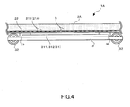
- FIG. 4 is a lateral view of a linear encoder according to the second embodiment of the present invention.
- the graduations 21 are formed on a surface on one side of the scale 2, while the bearing 32 abuts against a surface on the other side of the scale 2, whereby the scale 2 serves as a plate member interposed between the reading part 31 and the graduations 21.
- the second embodiment is different from the first embodiment in that the linear encoder 1A includes a scale 2A having graduations 21A formed on a surface of the scale 2A (a surface on a head 3 side) and arranged along the longitudinal direction of the scale 2A, and a plate member 22 interposed between the reading part 31 and the graduations 21A. Furthermore, each bearing 32 is situated on the head 3 so as to abut against a surface of the plate member 22.
- the plate member 22 is made of glass, and is attached to the scale 2A via an adhesive B so as to cover the graduations 21A.
- the scale 2A may have a pattern of protrusions other than the graduations 21A.
- the protrusions are formed to be the same in thickness as the graduations 21A, and arranged laterally outside the graduations 21A. With such protrusions, the scale 2A and the plate member 22 are joined parallel to each other securely.
- FIG. 5 is a lateral view of a linear encoder according to the third embodiment of the present invention.
- the linear encoder 1 includes the head 3 having the reading part 31.
- the reading part 31 is formed on a surface of the head 3 (a surface on the scale 2 side).
- a linear encoder 1B includes a head 3B having a reading part 31B.
- the head 3B has a plate 34 placed so as to face a surface of a scale 2 on which graduations 21 are formed.
- the reading part 31B is formed on the scale 2 side surface of the plate 34.
- the plate 34 is fixed to the head 3B via a support 341 situated so as not to come in contact with the scale 2.
- the third embodiment working effects similar to those in (1), (2), and (4) in the description of the first embodiment are produced.
- the third embodiment has the following working effect.
- the present invention is not limited to the previously described embodiments.
- the present invention encompasses any alterations and modifications which fall within the scope of accomplishment of the objective(s) thereof.
- the bearing 32 serves as a spacer to maintain a distance between the scale 2, 2A and the head 3, 3B, by abutting against a surface of the scale 2, 2A.
- the spacer is not necessarily be a bearing.
- the spacer may be a plastic column and the like.
- the bearing 32 is placed in such a manner that a path of the bearing 32 and the graduations 21, 21A overlap each other.
- the bearing 32 may be placed in such a manner that a path of the bearing 32 and the graduations 21, 21A do not overlap each other.
- the reading part 31, 31B is configured to read the graduations 21, 21A by means of electromagnetic induction.
- the reading part 31, 31B may be configured to read the graduations 21, 21A by a different method, such as measurement by means of capacitance.
- the plate member 22 is made of glass. However, a material other than glass may be applied to the plate member 22.
- the present invention is suitably applicable to a linear encoder.
Landscapes
- Physics & Mathematics (AREA)
- General Physics & Mathematics (AREA)
- Transmission And Conversion Of Sensor Element Output (AREA)
Abstract
Description
- The present invention relates to a linear encoder.
- It is known that a linear encoder conventionally includes a plate-type scale and a head which moves along the longitudinal direction of the scale. The scale has graduations formed on a surface thereof. The graduations are arranged along the longitudinal direction of the scale. The head has a reading part which detects an amount of a relative movement of the head with respect to the scale by reading the graduations formed on the scale.
- For example, a scale apparatus (a linear encoder) described in
JP 04-102423 - The movable member also functions as a spacer to maintain a distance between the scale and the detection head.
- For a linear scale, as a method by which a reading part of a head reads graduations formed on a scale, an electromagnetic induction method, a capacitance method, a photoelectric method, and the like are applicable. Whatever method is used, a distance between the graduations formed on the scale and the reading part situated on the head is desirably small,'because reducing the above distance improves the accuracy of detecting an amount of a relative movement of the head with respect to the scale. In the scale apparatus described in
JP 04-102423 -
FIG. 6 is a diagram illustrating a conventional linear encoder.FIG. 7 is a lateral view of the conventional linear encoder. More specifically,FIG. 6 illustrates the linear encoder as viewed from the scale side, andFIG. 7 illustrates the linear encoder ofFIG. 6 as viewed from the upper side ofFIG. 6 . - As shown in
FIGS. 6 and7 , the conventionallinear encoder 100 includes a plate-type scale 110, and ahead 120 configured to move along the longitudinal direction of the scale 110 (the right-left direction inFIGS. 6 and7 ). - The
scale 110 hasgraduations 111 formed on a surface thereof (a surface on thehead 120 side). Thegraduations 111 are arranged along the longitudinal direction of thescale 110. Thegraduations 111 are formed of a pattern of annular-shaped scale coils 111A regularly arrayed at predetermined pitch along the longitudinal direction of thescale 110. Thescale 110 is made of glass. Also, thescale coils 111A are formed in rows of three as counted in the transverse direction of thescale 110. - The
head 120 has areading part 121 configured to detect an amount of a relative movement of thehead 120 with respect to thescale 110 by reading thegraduations 111 formed on thescale 110. Thereading part 121 includes anexcitation coil 121A formed in a substantially annular shape, and a plurality ofdetection coils 121B formed inside theexcitation coil 121A. Theexcitation coil 121A is formed in a substantially elliptic shape having a long axis extending along the longitudinal direction of thescale 110. Further, theexcitation coil 121A enclosing thedetection coils 121B are formed in rows of three as counted in the transverse direction of thescale 110. - In the above
linear encoder 100, when an electric current is applied to theexcitation coil 121A, an electromotive current is generated in thescale coil 111A forming thegraduations 111, and subsequently in thedetection coil 121B. Then, when thehead 120 moves with respect to thescale 110, electromagnetic couplings among thecoils head 120. Based on this, thelinear encoder 100 detects a sinusoidal signal with a period equal to the pitch of thescale coils 111A, through thedetection coil 121B. By reference to the sinusoidal signal, thelinear encoder 100 detects an amount of a relative movement of thehead 120 with respect to thescale 110. In other words, thelinear encoder 100 is configured as a linear encoder of electromagnetic induction type. -
FIG. 8 is an exploded perspective view of the conventional linear encoder, showing a scale and a head in separated positions. - The
head 120 includes, as shown inFIGS. 6 to 8 , threebearings 122 each having a rotation axis extending along the transverse direction of thescale 110, and twobearings 123 each having a rotation axis extending along a direction in which thescale 110 and thehead 120 face each other. Thehead 120 is placed in such a manner that a peripheral surface of thebearing 122 is pressed against a surface of thescale 110, and at the same time a peripheral surface of thebearing 123 is pressed against a lateral surface of thescale 110. - As shown in
FIG. 7 , each of thebearings 122 is situated on thehead 120 so as to project above thereading part 121 toward thescale 110. This means the bearing 122 functions as a spacer which maintains a distance between thescale 110 and thehead 120 by abutting against the surface of thescale 110. - With this configuration, when the
head 120 moves with respect to thescale 110, the bearing 122 rolls on the surface of thescale 110. In thelinear encoder 100, therefore, as shown inFIG. 6 , a path of thebearing 122 is spaced apart from thegraduations 111. This prevents thebearing 122 from making contact with thegraduations 111 when rolling. If thebearing 122 touches thegraduations 111, thebearing 122 may damage thegraduations 111, or a distance between thegraduations 111 and thereading part 121 changes due to an uneven surface caused by thegraduations 111, which decreases the measurement accuracy of thelinear encoder 100. - On the other hand, transverse lengths of the
scale 110 and thehead 120 become longer, in order to place thebearing 122 such that the path of thebearing 122 is spaced apart from thegraduations 111. As a result, the entire size of thelinear encoder 100 becomes undesirably large. - In view of the above problem, it is an objective of the present invention to provide a linear encoder, the entire size of which is able to be reduced by reducing transverse lengths of a scale and a head included in the linear encoder.
- The linear encoder according to an embodiment of the present invention includes a plate-type scale with graduations formed on a surface of the scale. The graduations are formed along the longitudinal direction of the scale. The linear encoder also includes a head configured to move along the longitudinal direction of the scale. The head has a reading part configured to detect an amount of a relative movement of the head with respect to the scale by reading the graduations formed on the scale. The head includes a spacer configured to maintain a distance between the scale and the head by abutting against a surface of the scale. The scale includes a plate member interposed between the graduations and the reading part. The spacer is situated on the head so as to abut against a surface of the plate member.
- According to such a configuration, the spacer does not make contact with the graduations even if a path of the spacer and the graduations are arranged close to each other, as the spacer is situated on the head so as to abut against the surface of the plate member. In such linear encoder, therefore, the spacer is able to be situated in such a manner that a path of the spacer and the graduations are arranged close to each other, without damaging the graduations or reducing measurement accuracy. This makes it possible to reduce transverse lengths of the scale and the head in the linear encoder. As a result, the entire size of the linear encoder is able to be reduced.
- In a preferred embodiment of the present invention, the spacer is situated on the head in such a manner that a path of the spacer and the graduations overlap each other.
- According to such a configuration, it is possible to further reduce transverse lengths of the scale and the head in the linear encoder, as the spacer is situated on the head in such a manner that a path of the spacer and the graduations overlap each other. As a result, the entire size of the linear encoder is able to be further reduced.
- In a preferred embodiment of the present invention, the graduations are formed on a surface on one side of the scale, while the spacer abuts against a surface on the other side of the scale, so that the scale can serve as a plate member.
- According to such a configuration, since the scale serves as a plate member, it is possible to avoid adding a new member, as well as to reduce transverse lengths of the scale and the head in the linear encoder. As a result, the entire size of the linear encoder is able to be reduced.
- In a preferred embodiment of the present invention, a plate member is attached to the scale so as to cover the graduations, so that the plate member can be interposed between the reading part and the graduations.
- According to such a configuration, the linear encoder is able to be designed more flexibly, as materials for the scale and the plate member can be selected separately.
- In a preferred embodiment of the present invention, the plate member is made of glass.
- According to such a configuration, in the linear encoder, a distance between the reading part and the graduations is stable while the head moves with respect to the scale, since glass provides superior flatness to other materials. As a consequence, the linear encoder improves measurement accuracy.
- In a preferred embodiment of the present invention, the reading part reads the graduations by means of electromagnetic induction.
- According to such a configuration, the linear encoder, which is of an electromagnetic induction type, is able to maintain high detection accuracy even if a distance between the reading part and the graduations is increased, compared with linear encoders of a capacitance type and a photoelectric type. As a consequence, the entire size of the linear encoder is able to be reduced by reducing transverse lengths of the scale and the head, without decreasing the measurement accuracy of the linear encoder.
-
-
FIG. 1 is a diagram illustrating a linear encoder according to a first embodiment of the present invention; -
FIG. 2 is a lateral view of the linear encoder; -
FIG. 3 is an exploded perspective view of the linear encoder, showing a scale and a head in separated positions; -
FIG. 4 is a lateral view of a linear encoder according to a second embodiment of the present invention; -
FIG. 5 is a lateral view of a linear encoder according to a third embodiment of the present invention; -
FIG. 6 is a diagram illustrating a conventional linear encoder; -
FIG. 7 is a lateral view of the conventional linear encoder; and -
FIG. 8 is an exploded perspective view of the conventional linear encoder, showing a scale and a head in separated positions. - Hereinafter, a first embodiment of the present invention will be described with reference to the drawings.
-
FIG. 1 is a diagram illustrating a linear encoder according to a first embodiment of the present invention.FIG. 2 is a lateral view of the linear encoder. More specifically,FIG. 1 illustrates the linear encoder as viewed from the scale side, andFIG. 2 illustrates the linear encoder ofFIG. 1 as viewed from the upper side ofFIG. 1 . - The
linear encoder 1 includes, as shown inFIGS. 1 and2 , a plate-type scale 2, and ahead 3 configured to move along the longitudinal direction of the scale 2 (the right-left direction inFIGS. 1 and2 ). - The
scale 2 hasgraduations 21 formed on a surface thereof (a surface on a side opposite to thehead 3 side). Thegraduations 21 are arranged along the longitudinal direction of thescale 2. Thegraduations 21 are formed of a pattern of annular-shaped scale coils 211 regularly arrayed at predetermined pitch along the longitudinal direction of thescale 2. Thescale 2 is made of glass. Also, the scale coils 211 are formed in rows of three as counted in the transverse direction of thescale 2. - The
head 3 has a readingpart 31 configured to detect an amount of a relative movement of thehead 3 with respect to thescale 2 by reading thegraduations 21 formed on thescale 2. The readingpart 31 is situated on a surface of the head 3 (a surface on thescale 2 side). The readingpart 31 includes anexcitation coil 311 formed in a substantially annular shape, and a plurality of detection coils 312 formed inside theexcitation coil 311. This means the readingpart 31 is configured to read thegraduations 21 by means of electromagnetic induction. Theexcitation coil 311 is formed in a substantially elliptic shape having a long axis extending along the longitudinal direction of thescale 2. Further, theexcitation coil 311 enclosing the detection coils 312 are formed in rows of three as counted in the transverse direction of thescale 2. -
FIG. 3 is an exploded perspective view of the linear encoder, showing the scale and the head in separated positions. - The
head 3 includes, as shown inFIGS. 1 to 3 , fourbearings 32 each having a rotation axis extending along the transverse direction of thescale 2, and twobearings 33 each having a rotation axis extending along a direction in which thescale 2 and thehead 3 face each other. Thehead 3 is placed in such a manner that a peripheral surface of thebearing 32 is pressed against a surface of thescale 2, and at the same time a peripheral surface of thebearing 33 is pressed against a lateral surface of thescale 2. - As shown in
FIG. 2 , each of thebearings 32 is situated on thehead 3 so as to project above the readingpart 31 toward thescale 2. This means the bearing 32 functions as a spacer to maintain a distance between thescale 2 and thehead 3 by abutting against the surface of thescale 2. - Each of the
bearings 32 is situated, as shown inFIG. 1 , in such a manner that a path of thebearing 32 and thegraduations 21 overlap each other. Moreover, in thelinear encoder 1, as shown inFIG. 2 , thegraduations 21 are formed on a surface on one side of the scale 2 (a surface on a side opposite to thehead 3 side), while thebearing 32 abuts against a surface on the other side of the scale 2 (a surface on thehead 3 side). In other words, in thelinear encoder 1, thescale 2 serves as a plate member interposed between the readingpart 31 and thegraduations 21. Therefore, when thehead 3 moves with respect to thescale 2, the bearing 32 rolls on the surface of thescale 2 on the opposite side to the surface on which thegraduations 21 are formed. - In the foregoing embodiment, the following working effects are produced.
- (1) In the
linear encoder 1, thegraduations 21 are formed on a surface on one side of thescale 2, while thebearing 32 abuts against a surface on the other side of thescale 2. Accordingly, thebearing 32 does not make contact with thegraduations 21, even if a path of thebearing 32 and thegraduations 21 are arranged close to each other. In suchlinear encoder 1, therefore, thebearing 32 is able to be situated in such a manner that a path of thebearing 32 and thegraduations 21 are arranged close to each other, without damaging thegraduations 21 or reducing measurement accuracy. This makes it possible to reduce transverse lengths of thescale 2 and thehead 3 in thelinear encoder 1. As a result, the entire size of thelinear encoder 1 is able to be reduced. - (2) As each of the
bearings 32 is situated on the head in such a manner that a path of thebearing 32 and thegraduations 21 overlap each other, it is possible to further reduce transverse lengths of thescale 2 and thehead 3 in thelinear encoder 1. As a result, the entire size of thelinear encoder 1 is able to be further reduced. - (3) In the
linear encoder 1, thegraduations 21 are formed on a surface on one side of thescale 2, while thebearing 32 abuts against a surface on the other side of thescale 2, whereby thescale 2 serves as a plate member. This makes it possible to avoid adding a new member, as well as to reduce transverse lengths of thescale 2 and thehead 3 in thelinear encoder 1. As a result, the entire size of thelinear encoder 1 is able to be reduced. - (4) As the reading
part 31 is configured to read thegraduations 21 by means of electromagnetic induction, it is possible to reduce transverse lengths of thescale 2 and thehead 3 in thelinear encoder 1, and accordingly to reduce the entire size of thelinear encoder 1, without decreasing the measurement accuracy of thelinear encoder 1. - Hereinafter, a second embodiment of the present invention will be described with reference to the drawings. In the following description, previously described features will be denoted by the same reference signs as used in the preceding descriptions, and will not be discussed repeatedly.
-
FIG. 4 is a lateral view of a linear encoder according to the second embodiment of the present invention. - In the
linear encoder 1 of the first embodiment, thegraduations 21 are formed on a surface on one side of thescale 2, while thebearing 32 abuts against a surface on the other side of thescale 2, whereby thescale 2 serves as a plate member interposed between the readingpart 31 and thegraduations 21. - As shown in
FIG. 4 , the second embodiment is different from the first embodiment in that thelinear encoder 1A includes ascale 2A having graduations 21A formed on a surface of thescale 2A (a surface on ahead 3 side) and arranged along the longitudinal direction of thescale 2A, and aplate member 22 interposed between the readingpart 31 and thegraduations 21A. Furthermore, each bearing 32 is situated on thehead 3 so as to abut against a surface of theplate member 22. - The
plate member 22 is made of glass, and is attached to thescale 2A via an adhesive B so as to cover thegraduations 21A. - The
scale 2A may have a pattern of protrusions other than thegraduations 21A. The protrusions are formed to be the same in thickness as thegraduations 21A, and arranged laterally outside thegraduations 21A. With such protrusions, thescale 2A and theplate member 22 are joined parallel to each other securely. - In the second embodiment, working effects similar to those in (2) and (4) in the description of the first embodiment are produced. In addition, the second embodiment has the following working effects.
- (5) As the
bearing 32 is situated on thehead 3 so as to abut against a surface of theplate member 22, thebearing 32 does not make contact with thegraduations 21A even if a path of thebearing 32 and thegraduations 21A are arranged close to each other. In suchlinear encoder 1A, therefore, thebearing 32 is able to be situated in such a manner that a path of thebearing 32 and thegraduations 21A are arranged close to each other, without damaging thegraduations 21A or reducing measurement accuracy. This makes it possible to reduce transverse lengths of thescale 2A and thehead 3 in thelinear encoder 1A. As a result, the entire size of thelinear encoder 1A is able to be reduced. - (6) The
linear encoder 1A is able to be designed more flexibly, as materials for thescale 2A and theplate member 22 can be selected separately. - (7) In the
linear encoder 1A, as theplate member 22 is made of glass, a distance between the readingpart 31 and thegraduations 21A is stable while thehead 3 moves with respect to thescale 2A. As a consequence, thelinear encoder 1A improves measurement accuracy. - Hereinafter, a third embodiment of the present invention will be described with reference to the drawings. In the following description, previously described features will be denoted by the same reference signs as used in the preceding descriptions, and will not be discussed repeatedly.
-
FIG. 5 is a lateral view of a linear encoder according to the third embodiment of the present invention. - In the first embodiment, the
linear encoder 1 includes thehead 3 having the readingpart 31. The readingpart 31 is formed on a surface of the head 3 (a surface on thescale 2 side). - In the third embodiment, a
linear encoder 1B includes ahead 3B having a reading part 31B. Different from the first embodiment, however, thehead 3B has aplate 34 placed so as to face a surface of ascale 2 on whichgraduations 21 are formed. The reading part 31B is formed on thescale 2 side surface of theplate 34. Theplate 34 is fixed to thehead 3B via asupport 341 situated so as not to come in contact with thescale 2. - In the third embodiment, working effects similar to those in (1), (2), and (4) in the description of the first embodiment are produced. In addition, the third embodiment has the following working effect.
- (8) In the
linear encoder 1B, thegraduations 21 are formed on a surface on one side of thescale 2, while thebearing 32 abuts against a surface on the other side of thescale 2, whereby thescale 2 serves as a plate member. This makes it possible to reduce transverse lengths of thescale 2 and thehead 3 in thelinear encoder 1B. As a result, the entire size of thelinear encoder 1B is able to be reduced. - The present invention is not limited to the previously described embodiments. The present invention encompasses any alterations and modifications which fall within the scope of accomplishment of the objective(s) thereof.
- For example, in the foregoing embodiments, the
bearing 32 serves as a spacer to maintain a distance between thescale head scale - In the foregoing embodiments, the
bearing 32 is placed in such a manner that a path of thebearing 32 and thegraduations bearing 32 and thegraduations - In the foregoing embodiments, the reading
part 31, 31B is configured to read thegraduations part 31, 31B may be configured to read thegraduations - In the second embodiment, the
plate member 22 is made of glass. However, a material other than glass may be applied to theplate member 22. - As heretofore described, the present invention is suitably applicable to a linear encoder.
Claims (6)
- A linear encoder comprising:a plate-type scale with graduations formed on a surface of the scale so as to be arranged along a longitudinal direction of the scale; anda head configured to move along the longitudinal direction of the scale, the head having a reading part configured to detect an amount of a relative movement of the head with respect to the scale by reading the graduations formed on the scale, whereinthe head includes a spacer configured to maintain a distance between the scale and the head by abutting against a surface of the scale,the scale includes a plate member interposed between the reading part and the graduations,the spacer is situated on the head so as to abut against a surface of the plate member.
- The linear encoder according to claim 1, wherein the spacer is situated on the head in such a manner that a path of the spacer and the graduations overlap each other.
- The linear encoder according to claim 1 or 2, wherein the graduations are formed on a surface on one side of the scale, while the spacer abuts against a surface on the other side of the scale, so that the scale serves as the plate member.
- The linear encoder according to any one of claims 1 to 3, wherein the plate member is attached to the scale so as to cover the graduations, so that the plate member is interposed between the reading part and the graduations.
- The linear encoder according to claim 4, wherein the plate member is made of glass.
- The linear encoder according to any one of claims 1 to 5, wherein the reading part reads the graduations by way of electromagnetic induction.
Applications Claiming Priority (1)
| Application Number | Priority Date | Filing Date | Title |
|---|---|---|---|
| JP2014019408A JP6355349B2 (en) | 2014-02-04 | 2014-02-04 | Linear encoder |
Publications (2)
| Publication Number | Publication Date |
|---|---|
| EP2902750A1 true EP2902750A1 (en) | 2015-08-05 |
| EP2902750B1 EP2902750B1 (en) | 2021-04-07 |
Family
ID=52432643
Family Applications (1)
| Application Number | Title | Priority Date | Filing Date |
|---|---|---|---|
| EP15000262.4A Active EP2902750B1 (en) | 2014-02-04 | 2015-01-28 | Linear encoder |
Country Status (4)
| Country | Link |
|---|---|
| US (1) | US9506778B2 (en) |
| EP (1) | EP2902750B1 (en) |
| JP (1) | JP6355349B2 (en) |
| CN (1) | CN104819731B (en) |
Families Citing this family (3)
| Publication number | Priority date | Publication date | Assignee | Title |
|---|---|---|---|---|
| JP7225869B2 (en) * | 2019-02-06 | 2023-02-21 | コニカミノルタ株式会社 | Image forming apparatus and program |
| JP2021096160A (en) * | 2019-12-17 | 2021-06-24 | 株式会社ミツトヨ | Scale and encoder |
| EP4382870A1 (en) | 2022-12-08 | 2024-06-12 | Kaunas University of Technology | Anti-fogging incremental scales for optical encoders and fabrication method thereof |
Citations (5)
| Publication number | Priority date | Publication date | Assignee | Title |
|---|---|---|---|---|
| US4603480A (en) * | 1984-05-22 | 1986-08-05 | Mitutoyo Mfg. Co., Ltd. | Linear scale type displacement measuring instrument |
| JPH04102423U (en) | 1991-01-22 | 1992-09-03 | ソニーマグネスケール株式会社 | scale equipment |
| US20020066201A1 (en) * | 1999-03-19 | 2002-06-06 | Ludwig Boge | Position measuring device |
| EP2233893A2 (en) * | 2009-03-24 | 2010-09-29 | Mitutoyo Corporation | Linear Scale |
| EP2538180A2 (en) * | 2011-06-24 | 2012-12-26 | Mitutoyo Corporation | Structure for protecting scale graduations |
Family Cites Families (21)
| Publication number | Priority date | Publication date | Assignee | Title |
|---|---|---|---|---|
| FR2138401B1 (en) * | 1971-05-25 | 1973-05-25 | Telemecanique Electrique | |
| JPS4963973U (en) * | 1972-09-15 | 1974-06-05 | ||
| DE2628623C3 (en) * | 1976-06-25 | 1979-06-21 | Dr. Johannes Heidenhain Gmbh, 8225 Traunreut | Pressure device |
| US4400890A (en) * | 1981-10-26 | 1983-08-30 | Sony Corporation | Length measuring device |
| CN1008945B (en) * | 1985-05-25 | 1990-07-25 | 株式会社三豊制作所 | Linear type displacement measurement instrument |
| JPH04102423A (en) | 1990-08-23 | 1992-04-03 | Mitsubishi Electric Home Appliance Co Ltd | Suction device for floor use |
| JP3269232B2 (en) * | 1993-12-16 | 2002-03-25 | ソニー・プレシジョン・テクノロジー株式会社 | Magnetic flat linear scale |
| JP4233888B2 (en) * | 2003-02-14 | 2009-03-04 | 株式会社ミツトヨ | Inductive position detector |
| CN1275022C (en) * | 2003-08-18 | 2006-09-13 | 财团法人工业技术研究院 | Linear encoders and compression coupling mechanisms for linear encoders |
| US7485845B2 (en) * | 2005-12-06 | 2009-02-03 | Mitutoyo Corporation | Photoelectric encoder capable of effectively removing harmonic components |
| JP4971047B2 (en) * | 2007-06-19 | 2012-07-11 | 株式会社ミツトヨ | Surface reflective encoder scale and surface reflective encoder using the same |
| JP5616741B2 (en) * | 2010-10-08 | 2014-10-29 | 株式会社ミツトヨ | Encoder |
| JP5893857B2 (en) * | 2011-06-24 | 2016-03-23 | 株式会社ミツトヨ | Scale scale protection structure |
| JP5443452B2 (en) * | 2011-09-12 | 2014-03-19 | 株式会社大山光学 | Optical scale and optical unit including the same |
| JP5846686B2 (en) * | 2011-11-22 | 2016-01-20 | 株式会社ミツトヨ | Method for manufacturing scale of photoelectric encoder |
| JP5974329B2 (en) * | 2012-02-15 | 2016-08-23 | 株式会社ミツトヨ | Photoelectric encoder |
| US9488503B2 (en) * | 2014-01-03 | 2016-11-08 | Vernier Software & Technology, Llc | Cart movement detection system for a dynamics track |
| JP6327874B2 (en) * | 2014-02-04 | 2018-05-23 | 株式会社ミツトヨ | Inductive position measuring device |
| JP6225078B2 (en) * | 2014-07-10 | 2017-11-01 | オークマ株式会社 | Linear encoder |
| ES2621078T3 (en) * | 2014-11-26 | 2017-06-30 | Dr. Johannes Heidenhain Gmbh | Length measuring device |
| JP6437802B2 (en) * | 2014-11-28 | 2018-12-12 | 株式会社ミツトヨ | Optical encoder |
-
2014
- 2014-02-04 JP JP2014019408A patent/JP6355349B2/en active Active
-
2015
- 2015-01-26 CN CN201510038444.9A patent/CN104819731B/en active Active
- 2015-01-28 EP EP15000262.4A patent/EP2902750B1/en active Active
- 2015-01-30 US US14/609,802 patent/US9506778B2/en active Active
Patent Citations (5)
| Publication number | Priority date | Publication date | Assignee | Title |
|---|---|---|---|---|
| US4603480A (en) * | 1984-05-22 | 1986-08-05 | Mitutoyo Mfg. Co., Ltd. | Linear scale type displacement measuring instrument |
| JPH04102423U (en) | 1991-01-22 | 1992-09-03 | ソニーマグネスケール株式会社 | scale equipment |
| US20020066201A1 (en) * | 1999-03-19 | 2002-06-06 | Ludwig Boge | Position measuring device |
| EP2233893A2 (en) * | 2009-03-24 | 2010-09-29 | Mitutoyo Corporation | Linear Scale |
| EP2538180A2 (en) * | 2011-06-24 | 2012-12-26 | Mitutoyo Corporation | Structure for protecting scale graduations |
Also Published As
| Publication number | Publication date |
|---|---|
| JP6355349B2 (en) | 2018-07-11 |
| CN104819731A (en) | 2015-08-05 |
| US20150219475A1 (en) | 2015-08-06 |
| CN104819731B (en) | 2019-01-25 |
| JP2015145858A (en) | 2015-08-13 |
| EP2902750B1 (en) | 2021-04-07 |
| US9506778B2 (en) | 2016-11-29 |
Similar Documents
| Publication | Publication Date | Title |
|---|---|---|
| US9453773B2 (en) | Capacitive type 6-axial force/torque sensor | |
| JP6602566B2 (en) | Absolute encoder scale with plates repeatedly arranged against changing notches | |
| KR20180056712A (en) | Position detecting device | |
| JP6327874B2 (en) | Inductive position measuring device | |
| US9506778B2 (en) | Linear encoder | |
| US10302461B2 (en) | Rotation detection device | |
| US20150061655A1 (en) | Magnetic sensing device using magnetism to detect position | |
| US20180274944A1 (en) | Displacement detecting device and continuously variable transmission device | |
| JP6300027B2 (en) | Input device | |
| US10082406B2 (en) | Magnetic field detection apparatus and rotation detection apparatus | |
| JP5038691B2 (en) | How to use digital indicators and digital indicators | |
| JP2003156364A (en) | Direct actuator having slide position detector | |
| JP6145467B2 (en) | Position detection device | |
| US10677614B2 (en) | Encoder | |
| US7948230B2 (en) | Magnetic type digital-analogic position-sensing device | |
| JP6462248B2 (en) | Length measuring device, displacement amount calculating means, and alignment method between scale portion and pattern reading portion of length measuring device | |
| JP2018069250A (en) | Bending processing device | |
| JP6061126B2 (en) | Measuring element | |
| JP6517479B2 (en) | Method of measuring zero magnetic field position of permanent magnet | |
| JP2017142110A (en) | Gap sensor | |
| JP6438233B2 (en) | Displacement detector | |
| JP2007085823A (en) | Hardness meter | |
| RU130017U1 (en) | ANGULAR PNEUMATIC BRACKET | |
| WO2016171630A1 (en) | Incremental magnetic motion or rotation encoder with a reference pulse |
Legal Events
| Date | Code | Title | Description |
|---|---|---|---|
| PUAI | Public reference made under article 153(3) epc to a published international application that has entered the european phase |
Free format text: ORIGINAL CODE: 0009012 |
|
| 17P | Request for examination filed |
Effective date: 20150128 |
|
| AK | Designated contracting states |
Kind code of ref document: A1 Designated state(s): AL AT BE BG CH CY CZ DE DK EE ES FI FR GB GR HR HU IE IS IT LI LT LU LV MC MK MT NL NO PL PT RO RS SE SI SK SM TR |
|
| AX | Request for extension of the european patent |
Extension state: BA ME |
|
| 17P | Request for examination filed |
Effective date: 20151210 |
|
| RBV | Designated contracting states (corrected) |
Designated state(s): AL AT BE BG CH CY CZ DE DK EE ES FI FR GB GR HR HU IE IS IT LI LT LU LV MC MK MT NL NO PL PT RO RS SE SI SK SM TR |
|
| STAA | Information on the status of an ep patent application or granted ep patent |
Free format text: STATUS: EXAMINATION IS IN PROGRESS |
|
| 17Q | First examination report despatched |
Effective date: 20180607 |
|
| GRAP | Despatch of communication of intention to grant a patent |
Free format text: ORIGINAL CODE: EPIDOSNIGR1 |
|
| STAA | Information on the status of an ep patent application or granted ep patent |
Free format text: STATUS: GRANT OF PATENT IS INTENDED |
|
| INTG | Intention to grant announced |
Effective date: 20201217 |
|
| GRAS | Grant fee paid |
Free format text: ORIGINAL CODE: EPIDOSNIGR3 |
|
| GRAA | (expected) grant |
Free format text: ORIGINAL CODE: 0009210 |
|
| STAA | Information on the status of an ep patent application or granted ep patent |
Free format text: STATUS: THE PATENT HAS BEEN GRANTED |
|
| AK | Designated contracting states |
Kind code of ref document: B1 Designated state(s): AL AT BE BG CH CY CZ DE DK EE ES FI FR GB GR HR HU IE IS IT LI LT LU LV MC MK MT NL NO PL PT RO RS SE SI SK SM TR |
|
| REG | Reference to a national code |
Ref country code: GB Ref legal event code: FG4D |
|
| REG | Reference to a national code |
Ref country code: AT Ref legal event code: REF Ref document number: 1380265 Country of ref document: AT Kind code of ref document: T Effective date: 20210415 Ref country code: CH Ref legal event code: EP |
|
| REG | Reference to a national code |
Ref country code: DE Ref legal event code: R096 Ref document number: 602015067665 Country of ref document: DE |
|
| REG | Reference to a national code |
Ref country code: IE Ref legal event code: FG4D |
|
| REG | Reference to a national code |
Ref country code: LT Ref legal event code: MG9D |
|
| REG | Reference to a national code |
Ref country code: NL Ref legal event code: MP Effective date: 20210407 Ref country code: AT Ref legal event code: MK05 Ref document number: 1380265 Country of ref document: AT Kind code of ref document: T Effective date: 20210407 |
|
| PG25 | Lapsed in a contracting state [announced via postgrant information from national office to epo] |
Ref country code: HR Free format text: LAPSE BECAUSE OF FAILURE TO SUBMIT A TRANSLATION OF THE DESCRIPTION OR TO PAY THE FEE WITHIN THE PRESCRIBED TIME-LIMIT Effective date: 20210407 Ref country code: BG Free format text: LAPSE BECAUSE OF FAILURE TO SUBMIT A TRANSLATION OF THE DESCRIPTION OR TO PAY THE FEE WITHIN THE PRESCRIBED TIME-LIMIT Effective date: 20210707 Ref country code: AT Free format text: LAPSE BECAUSE OF FAILURE TO SUBMIT A TRANSLATION OF THE DESCRIPTION OR TO PAY THE FEE WITHIN THE PRESCRIBED TIME-LIMIT Effective date: 20210407 Ref country code: LT Free format text: LAPSE BECAUSE OF FAILURE TO SUBMIT A TRANSLATION OF THE DESCRIPTION OR TO PAY THE FEE WITHIN THE PRESCRIBED TIME-LIMIT Effective date: 20210407 Ref country code: NL Free format text: LAPSE BECAUSE OF FAILURE TO SUBMIT A TRANSLATION OF THE DESCRIPTION OR TO PAY THE FEE WITHIN THE PRESCRIBED TIME-LIMIT Effective date: 20210407 Ref country code: FI Free format text: LAPSE BECAUSE OF FAILURE TO SUBMIT A TRANSLATION OF THE DESCRIPTION OR TO PAY THE FEE WITHIN THE PRESCRIBED TIME-LIMIT Effective date: 20210407 |
|
| PG25 | Lapsed in a contracting state [announced via postgrant information from national office to epo] |
Ref country code: SE Free format text: LAPSE BECAUSE OF FAILURE TO SUBMIT A TRANSLATION OF THE DESCRIPTION OR TO PAY THE FEE WITHIN THE PRESCRIBED TIME-LIMIT Effective date: 20210407 Ref country code: RS Free format text: LAPSE BECAUSE OF FAILURE TO SUBMIT A TRANSLATION OF THE DESCRIPTION OR TO PAY THE FEE WITHIN THE PRESCRIBED TIME-LIMIT Effective date: 20210407 Ref country code: NO Free format text: LAPSE BECAUSE OF FAILURE TO SUBMIT A TRANSLATION OF THE DESCRIPTION OR TO PAY THE FEE WITHIN THE PRESCRIBED TIME-LIMIT Effective date: 20210707 Ref country code: PL Free format text: LAPSE BECAUSE OF FAILURE TO SUBMIT A TRANSLATION OF THE DESCRIPTION OR TO PAY THE FEE WITHIN THE PRESCRIBED TIME-LIMIT Effective date: 20210407 Ref country code: PT Free format text: LAPSE BECAUSE OF FAILURE TO SUBMIT A TRANSLATION OF THE DESCRIPTION OR TO PAY THE FEE WITHIN THE PRESCRIBED TIME-LIMIT Effective date: 20210809 Ref country code: ES Free format text: LAPSE BECAUSE OF FAILURE TO SUBMIT A TRANSLATION OF THE DESCRIPTION OR TO PAY THE FEE WITHIN THE PRESCRIBED TIME-LIMIT Effective date: 20210407 Ref country code: IS Free format text: LAPSE BECAUSE OF FAILURE TO SUBMIT A TRANSLATION OF THE DESCRIPTION OR TO PAY THE FEE WITHIN THE PRESCRIBED TIME-LIMIT Effective date: 20210807 Ref country code: GR Free format text: LAPSE BECAUSE OF FAILURE TO SUBMIT A TRANSLATION OF THE DESCRIPTION OR TO PAY THE FEE WITHIN THE PRESCRIBED TIME-LIMIT Effective date: 20210708 Ref country code: LV Free format text: LAPSE BECAUSE OF FAILURE TO SUBMIT A TRANSLATION OF THE DESCRIPTION OR TO PAY THE FEE WITHIN THE PRESCRIBED TIME-LIMIT Effective date: 20210407 |
|
| REG | Reference to a national code |
Ref country code: DE Ref legal event code: R097 Ref document number: 602015067665 Country of ref document: DE |
|
| PG25 | Lapsed in a contracting state [announced via postgrant information from national office to epo] |
Ref country code: RO Free format text: LAPSE BECAUSE OF FAILURE TO SUBMIT A TRANSLATION OF THE DESCRIPTION OR TO PAY THE FEE WITHIN THE PRESCRIBED TIME-LIMIT Effective date: 20210407 Ref country code: EE Free format text: LAPSE BECAUSE OF FAILURE TO SUBMIT A TRANSLATION OF THE DESCRIPTION OR TO PAY THE FEE WITHIN THE PRESCRIBED TIME-LIMIT Effective date: 20210407 Ref country code: CZ Free format text: LAPSE BECAUSE OF FAILURE TO SUBMIT A TRANSLATION OF THE DESCRIPTION OR TO PAY THE FEE WITHIN THE PRESCRIBED TIME-LIMIT Effective date: 20210407 Ref country code: DK Free format text: LAPSE BECAUSE OF FAILURE TO SUBMIT A TRANSLATION OF THE DESCRIPTION OR TO PAY THE FEE WITHIN THE PRESCRIBED TIME-LIMIT Effective date: 20210407 Ref country code: SK Free format text: LAPSE BECAUSE OF FAILURE TO SUBMIT A TRANSLATION OF THE DESCRIPTION OR TO PAY THE FEE WITHIN THE PRESCRIBED TIME-LIMIT Effective date: 20210407 Ref country code: SM Free format text: LAPSE BECAUSE OF FAILURE TO SUBMIT A TRANSLATION OF THE DESCRIPTION OR TO PAY THE FEE WITHIN THE PRESCRIBED TIME-LIMIT Effective date: 20210407 |
|
| PLBE | No opposition filed within time limit |
Free format text: ORIGINAL CODE: 0009261 |
|
| STAA | Information on the status of an ep patent application or granted ep patent |
Free format text: STATUS: NO OPPOSITION FILED WITHIN TIME LIMIT |
|
| 26N | No opposition filed |
Effective date: 20220110 |
|
| PG25 | Lapsed in a contracting state [announced via postgrant information from national office to epo] |
Ref country code: IS Free format text: LAPSE BECAUSE OF FAILURE TO SUBMIT A TRANSLATION OF THE DESCRIPTION OR TO PAY THE FEE WITHIN THE PRESCRIBED TIME-LIMIT Effective date: 20210807 Ref country code: AL Free format text: LAPSE BECAUSE OF FAILURE TO SUBMIT A TRANSLATION OF THE DESCRIPTION OR TO PAY THE FEE WITHIN THE PRESCRIBED TIME-LIMIT Effective date: 20210407 |
|
| PG25 | Lapsed in a contracting state [announced via postgrant information from national office to epo] |
Ref country code: IT Free format text: LAPSE BECAUSE OF FAILURE TO SUBMIT A TRANSLATION OF THE DESCRIPTION OR TO PAY THE FEE WITHIN THE PRESCRIBED TIME-LIMIT Effective date: 20210407 |
|
| PG25 | Lapsed in a contracting state [announced via postgrant information from national office to epo] |
Ref country code: MC Free format text: LAPSE BECAUSE OF FAILURE TO SUBMIT A TRANSLATION OF THE DESCRIPTION OR TO PAY THE FEE WITHIN THE PRESCRIBED TIME-LIMIT Effective date: 20210407 |
|
| REG | Reference to a national code |
Ref country code: CH Ref legal event code: PL |
|
| REG | Reference to a national code |
Ref country code: BE Ref legal event code: MM Effective date: 20220131 |
|
| PG25 | Lapsed in a contracting state [announced via postgrant information from national office to epo] |
Ref country code: LU Free format text: LAPSE BECAUSE OF NON-PAYMENT OF DUE FEES Effective date: 20220128 |
|
| PG25 | Lapsed in a contracting state [announced via postgrant information from national office to epo] |
Ref country code: FR Free format text: LAPSE BECAUSE OF NON-PAYMENT OF DUE FEES Effective date: 20220131 Ref country code: BE Free format text: LAPSE BECAUSE OF NON-PAYMENT OF DUE FEES Effective date: 20220131 |
|
| PG25 | Lapsed in a contracting state [announced via postgrant information from national office to epo] |
Ref country code: LI Free format text: LAPSE BECAUSE OF NON-PAYMENT OF DUE FEES Effective date: 20220131 Ref country code: CH Free format text: LAPSE BECAUSE OF NON-PAYMENT OF DUE FEES Effective date: 20220131 |
|
| PG25 | Lapsed in a contracting state [announced via postgrant information from national office to epo] |
Ref country code: IE Free format text: LAPSE BECAUSE OF NON-PAYMENT OF DUE FEES Effective date: 20220128 |
|
| PG25 | Lapsed in a contracting state [announced via postgrant information from national office to epo] |
Ref country code: HU Free format text: LAPSE BECAUSE OF FAILURE TO SUBMIT A TRANSLATION OF THE DESCRIPTION OR TO PAY THE FEE WITHIN THE PRESCRIBED TIME-LIMIT; INVALID AB INITIO Effective date: 20150128 |
|
| PG25 | Lapsed in a contracting state [announced via postgrant information from national office to epo] |
Ref country code: MK Free format text: LAPSE BECAUSE OF FAILURE TO SUBMIT A TRANSLATION OF THE DESCRIPTION OR TO PAY THE FEE WITHIN THE PRESCRIBED TIME-LIMIT Effective date: 20210407 Ref country code: CY Free format text: LAPSE BECAUSE OF FAILURE TO SUBMIT A TRANSLATION OF THE DESCRIPTION OR TO PAY THE FEE WITHIN THE PRESCRIBED TIME-LIMIT Effective date: 20210407 |
|
| PG25 | Lapsed in a contracting state [announced via postgrant information from national office to epo] |
Ref country code: TR Free format text: LAPSE BECAUSE OF FAILURE TO SUBMIT A TRANSLATION OF THE DESCRIPTION OR TO PAY THE FEE WITHIN THE PRESCRIBED TIME-LIMIT Effective date: 20210407 |
|
| PG25 | Lapsed in a contracting state [announced via postgrant information from national office to epo] |
Ref country code: MT Free format text: LAPSE BECAUSE OF FAILURE TO SUBMIT A TRANSLATION OF THE DESCRIPTION OR TO PAY THE FEE WITHIN THE PRESCRIBED TIME-LIMIT Effective date: 20210407 |
|
| PGFP | Annual fee paid to national office [announced via postgrant information from national office to epo] |
Ref country code: GB Payment date: 20260123 Year of fee payment: 12 |
|
| PGFP | Annual fee paid to national office [announced via postgrant information from national office to epo] |
Ref country code: DE Payment date: 20260121 Year of fee payment: 12 |