EP2902728A1 - Automatische Erkennung von Kältemittelfüllmengen in Kältekreisläufen - Google Patents
Automatische Erkennung von Kältemittelfüllmengen in Kältekreisläufen Download PDFInfo
- Publication number
- EP2902728A1 EP2902728A1 EP15150586.4A EP15150586A EP2902728A1 EP 2902728 A1 EP2902728 A1 EP 2902728A1 EP 15150586 A EP15150586 A EP 15150586A EP 2902728 A1 EP2902728 A1 EP 2902728A1
- Authority
- EP
- European Patent Office
- Prior art keywords
- expansion valve
- refrigerant
- determined
- opening degree
- target
- Prior art date
- Legal status (The legal status is an assumption and is not a legal conclusion. Google has not performed a legal analysis and makes no representation as to the accuracy of the status listed.)
- Granted
Links
Images

Classifications
-
- F—MECHANICAL ENGINEERING; LIGHTING; HEATING; WEAPONS; BLASTING
- F25—REFRIGERATION OR COOLING; COMBINED HEATING AND REFRIGERATION SYSTEMS; HEAT PUMP SYSTEMS; MANUFACTURE OR STORAGE OF ICE; LIQUEFACTION SOLIDIFICATION OF GASES
- F25B—REFRIGERATION MACHINES, PLANTS OR SYSTEMS; COMBINED HEATING AND REFRIGERATION SYSTEMS; HEAT PUMP SYSTEMS
- F25B49/00—Arrangement or mounting of control or safety devices
- F25B49/005—Arrangement or mounting of control or safety devices of safety devices
-
- F—MECHANICAL ENGINEERING; LIGHTING; HEATING; WEAPONS; BLASTING
- F25—REFRIGERATION OR COOLING; COMBINED HEATING AND REFRIGERATION SYSTEMS; HEAT PUMP SYSTEMS; MANUFACTURE OR STORAGE OF ICE; LIQUEFACTION SOLIDIFICATION OF GASES
- F25B—REFRIGERATION MACHINES, PLANTS OR SYSTEMS; COMBINED HEATING AND REFRIGERATION SYSTEMS; HEAT PUMP SYSTEMS
- F25B30/00—Heat pumps
- F25B30/02—Heat pumps of the compression type
-
- F—MECHANICAL ENGINEERING; LIGHTING; HEATING; WEAPONS; BLASTING
- F24—HEATING; RANGES; VENTILATING
- F24H—FLUID HEATERS, e.g. WATER OR AIR HEATERS, HAVING HEAT-GENERATING MEANS, e.g. HEAT PUMPS, IN GENERAL
- F24H4/00—Fluid heaters characterised by the use of heat pumps
-
- F—MECHANICAL ENGINEERING; LIGHTING; HEATING; WEAPONS; BLASTING
- F25—REFRIGERATION OR COOLING; COMBINED HEATING AND REFRIGERATION SYSTEMS; HEAT PUMP SYSTEMS; MANUFACTURE OR STORAGE OF ICE; LIQUEFACTION SOLIDIFICATION OF GASES
- F25B—REFRIGERATION MACHINES, PLANTS OR SYSTEMS; COMBINED HEATING AND REFRIGERATION SYSTEMS; HEAT PUMP SYSTEMS
- F25B2500/00—Problems to be solved
- F25B2500/22—Preventing, detecting or repairing leaks of refrigeration fluids
-
- F—MECHANICAL ENGINEERING; LIGHTING; HEATING; WEAPONS; BLASTING
- F25—REFRIGERATION OR COOLING; COMBINED HEATING AND REFRIGERATION SYSTEMS; HEAT PUMP SYSTEMS; MANUFACTURE OR STORAGE OF ICE; LIQUEFACTION SOLIDIFICATION OF GASES
- F25B—REFRIGERATION MACHINES, PLANTS OR SYSTEMS; COMBINED HEATING AND REFRIGERATION SYSTEMS; HEAT PUMP SYSTEMS
- F25B2500/00—Problems to be solved
- F25B2500/23—High amount of refrigerant in the system
-
- F—MECHANICAL ENGINEERING; LIGHTING; HEATING; WEAPONS; BLASTING
- F25—REFRIGERATION OR COOLING; COMBINED HEATING AND REFRIGERATION SYSTEMS; HEAT PUMP SYSTEMS; MANUFACTURE OR STORAGE OF ICE; LIQUEFACTION SOLIDIFICATION OF GASES
- F25B—REFRIGERATION MACHINES, PLANTS OR SYSTEMS; COMBINED HEATING AND REFRIGERATION SYSTEMS; HEAT PUMP SYSTEMS
- F25B2500/00—Problems to be solved
- F25B2500/24—Low amount of refrigerant in the system
-
- F—MECHANICAL ENGINEERING; LIGHTING; HEATING; WEAPONS; BLASTING
- F25—REFRIGERATION OR COOLING; COMBINED HEATING AND REFRIGERATION SYSTEMS; HEAT PUMP SYSTEMS; MANUFACTURE OR STORAGE OF ICE; LIQUEFACTION SOLIDIFICATION OF GASES
- F25B—REFRIGERATION MACHINES, PLANTS OR SYSTEMS; COMBINED HEATING AND REFRIGERATION SYSTEMS; HEAT PUMP SYSTEMS
- F25B2600/00—Control issues
- F25B2600/25—Control of valves
- F25B2600/2513—Expansion valves
-
- F—MECHANICAL ENGINEERING; LIGHTING; HEATING; WEAPONS; BLASTING
- F25—REFRIGERATION OR COOLING; COMBINED HEATING AND REFRIGERATION SYSTEMS; HEAT PUMP SYSTEMS; MANUFACTURE OR STORAGE OF ICE; LIQUEFACTION SOLIDIFICATION OF GASES
- F25B—REFRIGERATION MACHINES, PLANTS OR SYSTEMS; COMBINED HEATING AND REFRIGERATION SYSTEMS; HEAT PUMP SYSTEMS
- F25B2700/00—Sensing or detecting of parameters; Sensors therefor
- F25B2700/19—Pressures
- F25B2700/193—Pressures of the compressor
-
- F—MECHANICAL ENGINEERING; LIGHTING; HEATING; WEAPONS; BLASTING
- F25—REFRIGERATION OR COOLING; COMBINED HEATING AND REFRIGERATION SYSTEMS; HEAT PUMP SYSTEMS; MANUFACTURE OR STORAGE OF ICE; LIQUEFACTION SOLIDIFICATION OF GASES
- F25B—REFRIGERATION MACHINES, PLANTS OR SYSTEMS; COMBINED HEATING AND REFRIGERATION SYSTEMS; HEAT PUMP SYSTEMS
- F25B2700/00—Sensing or detecting of parameters; Sensors therefor
- F25B2700/19—Pressures
- F25B2700/193—Pressures of the compressor
- F25B2700/1931—Discharge pressures
-
- F—MECHANICAL ENGINEERING; LIGHTING; HEATING; WEAPONS; BLASTING
- F25—REFRIGERATION OR COOLING; COMBINED HEATING AND REFRIGERATION SYSTEMS; HEAT PUMP SYSTEMS; MANUFACTURE OR STORAGE OF ICE; LIQUEFACTION SOLIDIFICATION OF GASES
- F25B—REFRIGERATION MACHINES, PLANTS OR SYSTEMS; COMBINED HEATING AND REFRIGERATION SYSTEMS; HEAT PUMP SYSTEMS
- F25B2700/00—Sensing or detecting of parameters; Sensors therefor
- F25B2700/21—Temperatures
- F25B2700/2115—Temperatures of a compressor or the drive means therefor
- F25B2700/21151—Temperatures of a compressor or the drive means therefor at the suction side of the compressor
-
- F—MECHANICAL ENGINEERING; LIGHTING; HEATING; WEAPONS; BLASTING
- F25—REFRIGERATION OR COOLING; COMBINED HEATING AND REFRIGERATION SYSTEMS; HEAT PUMP SYSTEMS; MANUFACTURE OR STORAGE OF ICE; LIQUEFACTION SOLIDIFICATION OF GASES
- F25B—REFRIGERATION MACHINES, PLANTS OR SYSTEMS; COMBINED HEATING AND REFRIGERATION SYSTEMS; HEAT PUMP SYSTEMS
- F25B2700/00—Sensing or detecting of parameters; Sensors therefor
- F25B2700/21—Temperatures
- F25B2700/2115—Temperatures of a compressor or the drive means therefor
- F25B2700/21152—Temperatures of a compressor or the drive means therefor at the discharge side of the compressor
-
- F—MECHANICAL ENGINEERING; LIGHTING; HEATING; WEAPONS; BLASTING
- F25—REFRIGERATION OR COOLING; COMBINED HEATING AND REFRIGERATION SYSTEMS; HEAT PUMP SYSTEMS; MANUFACTURE OR STORAGE OF ICE; LIQUEFACTION SOLIDIFICATION OF GASES
- F25B—REFRIGERATION MACHINES, PLANTS OR SYSTEMS; COMBINED HEATING AND REFRIGERATION SYSTEMS; HEAT PUMP SYSTEMS
- F25B2700/00—Sensing or detecting of parameters; Sensors therefor
- F25B2700/21—Temperatures
- F25B2700/2116—Temperatures of a condenser
- F25B2700/21163—Temperatures of a condenser of the refrigerant at the outlet of the condenser
-
- F—MECHANICAL ENGINEERING; LIGHTING; HEATING; WEAPONS; BLASTING
- F25—REFRIGERATION OR COOLING; COMBINED HEATING AND REFRIGERATION SYSTEMS; HEAT PUMP SYSTEMS; MANUFACTURE OR STORAGE OF ICE; LIQUEFACTION SOLIDIFICATION OF GASES
- F25B—REFRIGERATION MACHINES, PLANTS OR SYSTEMS; COMBINED HEATING AND REFRIGERATION SYSTEMS; HEAT PUMP SYSTEMS
- F25B2700/00—Sensing or detecting of parameters; Sensors therefor
- F25B2700/21—Temperatures
- F25B2700/2117—Temperatures of an evaporator
- F25B2700/21175—Temperatures of an evaporator of the refrigerant at the outlet of the evaporator
Definitions
- the invention relates to a method for automatic detection of refrigerant charge in refrigeration circuits.
- the invention has for its object to determine refrigerant shortage or overfilling automatically.
- the detected opening degree of the expansion valve is larger than the target opening degree, there must be a refrigerant shortage, whereas if the detected opening degree of the expansion valve is smaller than the target opening degree by a predetermined deviation, there must be a refrigerant surplus.
- the refrigerant circuit can be switched off and / or a warning signal can be output.
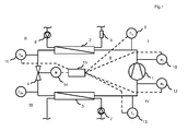
- the compressor 1 in the refrigerant circuit 8 has the task to raise the superheated refrigerant flowing from the evaporator 3 at the temperature T s of the evaporation pressure p 0 to the condensing pressure p c .
- the further superheated refrigerant vapor exits at the discharge nozzle of the compressor 1 with the hot gas temperature T d , and flows through the hot gas line to the condenser 2.
- the condenser 2 has the task to the superheated refrigerant vapor flowing from the compressor 1 to (cool), to liquefy and thereby to pass the enthalpy to the heating water, and then to subcool the refrigerant.
- the refrigerant flows in liquid form and still under condensing pressure p c through the liquid line to the electronic expansion valve 4.
- the subcooling of the refrigerant is necessary to ensure proper operation of the expansion valve 4, since gas bubbles the proper operation of the expansion valve. 4 would disturb. An incorrectly injected amount of refrigerant in the evaporator 3 would in turn damage the compressor 1.
- supercooling ⁇ T U improves performance, as more enthalpy is drawn from the source as subcooling increases.
- the electronic expansion valve 4 has the task to relax the supercooled refrigerant with the inlet temperature T EI of condensing pressure p c back to evaporation pressure p 0 so that it can get into the evaporator 3 via the injection line.
- the injected refrigerant amount is determined by the opening degree of the expansion valve 4.
- the opening degree of the expansion valve 4 is set in the case of an electronic expansion valve 4 with stepping motor 14 by a controller 15 on the number of steps of the stepping motor 14.
- the controlled variable used is the so-called overheating ⁇ T 0 , the difference between the evaporation temperature T 0 and compressor suction nozzle temperature, the suction temperature T s .
- the evaporation temperature T 0 is determined via the evaporation pressure p 0 , which is measured by the second pressure sensor 12, and corresponds to the temperature at which the entire refrigerant has evaporated.
- liquid refrigerant is evaporated.
- the necessary enthalpy of vaporization is withdrawn from the brine circuit connected to the primary side of the evaporator 3.
- the control 15 ensures that only so much refrigerant is injected from the electronic expansion valve 4 that it completely evaporates in the evaporator 3 and the compressor 1 is supplied with a predetermined superheating ⁇ T 0 via the suction line with the suction temperature T s .
- FIG. 2 shows the operation of the refrigeration cycle in the log p - h diagram. For comparison, certain operating points with Roman numerals I to IV in both the device according to FIG. 1 , as well as in the diagram according to FIG. 2 shown.
- IV represents the state downstream of the evaporator 3 upstream of the compressor 1.
- the refrigerant is in vapor form with the suction temperature T s and the evaporation pressure p 0 .
- the compressor 1 the refrigerant is compressed, whereby the pressure on the condensing pressure p c increases. At the same time the temperature rises to the hot gas temperature T d.
- the refrigerant is now in state I.
- the condenser 2 the refrigerant is isobaric cooled, whereby the refrigerant passes through the wet steam area and condenses out. After passing through the wet steam area, the liquid refrigerant is still slightly undercooled, so that the temperature T EI sets (state II).
- the refrigerant is depressurized to evaporating pressure p 0 and thereby cools to the temperature T E0 down (state III).
- the refrigerant absorbs isobaric heat, so that the refrigerant evaporates.
- the overheating ⁇ T o is an important factor for detecting the refrigerant shortage.
- the evaporation pressure p 0 is determined by means of the second pressure sensor 12 between the evaporator 3 and the compressor 1. From this it is possible to determine the temperature T 0 at which the wet steam region will leave. From the temperature T 0 at the evaporation pressure p 0 and the temperature of the second temperature sensor 13 between the evaporator 3 and the compressor 1, the superheating ⁇ T o is determined as the difference. The variable cross section of the expansion valve 4 is changed by means of the stepping motor 14 until a predetermined overheating ⁇ T o, should set.
- the opening degree of the expansion valve 4 at a predetermined overheating .DELTA.T o, to is determined and recorded.
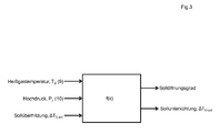
- a setpoint opening degree of the expansion valve 4 is determined from a stored characteristic map or algorithm for the overheating ⁇ T o, soll and the high pressure p c and the hot gas temperature T d ; this is in FIG. 3 shown. Now, the difference between the measured opening degree and the target opening degree of the expansion valve 4 is determined.
- the condensing pressure p c is determined. From this, the boiling temperature at which the wet steam region is left can be determined. From the boiling point at the condensing pressure p c and the temperature of the first temperature sensor 11 between the condenser 2 and expansion valve 4, the subcooling ⁇ T U is determined as the difference. From a stored map or algorithm is to the superheating .DELTA.T o, soll and the high pressure p c and the hot gas temperature T d, a target subcooling .DELTA.T U, soll determined. Now the difference between measured subcooling ⁇ T U and target subcooling ⁇ T U, soll is determined.
- the detected opening degree of the expansion valve 4 is larger than the target opening degree by a predetermined deviation, there is a refrigerant shortage, whereas if the detected opening degree of the expansion valve 4 is smaller than the target opening degree by a predetermined deviation, there is a refrigerant surplus.
- the specified deviations may be different for refrigerant shortage and excess refrigerant. If there is a deviation by a first, predetermined amount, a warning signal is initially output. If a second, larger, predetermined amount is exceeded, the refrigerant circuit is switched off.
Landscapes
- Engineering & Computer Science (AREA)
- Physics & Mathematics (AREA)
- Mechanical Engineering (AREA)
- Thermal Sciences (AREA)
- General Engineering & Computer Science (AREA)
- Air Conditioning Control Device (AREA)
- Chemical & Material Sciences (AREA)
- Combustion & Propulsion (AREA)
- Compression-Type Refrigeration Machines With Reversible Cycles (AREA)
Abstract
Description
- Die Erfindung bezieht sich auf ein Verfahren zur automatischen Erkennung von Kältemittelfüllmengen in Kältekreisläufen.
- Beim Befüllen des Kältekreislaufs kann es zu einem Überfüllen oder Kältemittelmangel kommen. Durch Leckagen kann es danach zu einem Kältemittelverlust kommen. Für einen optimalen Betrieb des Kältekreislaufs ist es von größter Bedeutung, dass die korrekte Kältemittelmenge zur Verfügung steht. Häufig wird eine Abweichung erst bei einer Wartung oder Störung festgestellt, so dass der Kältekreislauf über einen längeren Zeitraum zumindest mit reduzierter Effizienz betrieben wird. In ungünstigen Fällen kann es zu Schädigungen der Anlage führen.
- Der Erfindung liegt die Aufgabe zugrunde, Kältemittelmangel oder -überfüllung automatisch festzustellen.
- Dies wird gemäß den Merkmalen des unabhängigen Anspruchs 1 dadurch gelöst, dass bei einem Kältemittelkreislaufs einer Wärmepumpe mit einem Expansionsventil mit variablen Querschnitt zunächst die Unterkühlung stromab des Kondensators bestimmt wird, zu dieser Unterkühlung wird aus einem hinterlegten Kennfeld oder Algorithmus ein Sollöffnungsgrad des Expansionsventils bestimmt. Der Querschnitt des Expansionsventils des Kältemittelkreislaufs wird verändert, bis sich stromab des Verdampfers eine vorgegebene Überhitzung einstellt. In diesem Betriebszustand wird der Öffnungsgrad des Expansionsventils mit dem Sollöffnungsgrad verglichen. Liegt eine signifikante Abweichung vor, so muss ein Kältemittelmangel oder Kältemittelüberschuss vorliegen.
- Vorteilhafte Ausgestaltungen der Erfindung ergeben sich durch die Merkmale der abhängigen Ansprüche.
- So muss, wenn der erfasste Öffnungsgrad des Expansionsventils um eine vorgegebene Abweichung größer ist als der Sollöffnungsgrad, ein Kältemittelmangel vorliegen, während wenn der erfasste Öffnungsgrad des Expansionsventils um eine vorgegebene Abweichung kleiner als der Sollöffnungsgrad ist, ein Kältemittelüberschuss vorliegen muss.
- Die vorgegebenen Abweichungen bei Kältemittelmangel und Kältemittelüberschuss können hierbei unterschiedlich sein.
- Als Resultat kann bei Überschreitung der Abweichung der Kältemittelkreislauf abgeschaltet und / oder ein Warnsignal ausgegeben werden. Hierbei ist es möglich, bei Überschreitung einer ersten, vorgegebenen Abweichung ein Frühwarnsignal auszugeben und / oder bei Überschreitung einer zweiten, vorgegebenen Abweichung der Kältemittelkreislauf abzuschalten.
- Die Erfindung wird nun anhand der Figur detailliert erläutert.
-
Figur 1 zeigt einen Kältekreislauf 8 einer Wärmepumpe mit einem Kompressor 1, einem Kondensator 2, einem elektronischen Expansionsventil 4 mit variablem Querschnitt sowie einem Schrittmotor 14 als Antrieb und zur Erfassung des Öffnungsgrades, einem Verdampfer 3, einem ersten Temperatursensor 11 zwischen Kondensator 2 und Expansionsventil 4, einem ersten Drucksensor 10 zwischen Kompressor 1 und Kondensator 2, einem zweiten Temperatursensor 13 sowie einem zweiten Drucksensor 12 zwischen Verdampfer 3 und Kompressor 1 und einem dritten Temperatursensor 9 zwischen Kompressor 1 und Kondensator 2. Der Kondensator 2 ist mit einem Heizkreislauf mit einer Heizkreispumpe 6 sowie einem Volumenstromsensor 5 verbunden. Der Verdampfer 3 ist mit einem Solekreislauf mit Solekreispumpe 7 verbunden. Eine Regelung 15 dient der Regelung der Wärmepumpe. - Der Kompressor 1 in dem Kältekreis 8 hat die Aufgabe, das aus dem Verdampfer 3 strömende, überhitzte Kältemittel mit der Temperatur Ts von Verdampfungsdruck p0 auf Verflüssigungsdrucks pc anzuheben. Der weiter überhitzte Kältemitteldampf tritt am Druckstutzen des Kompressors 1 mit der Heißgastemperatur Td aus, und durchströmt die Heißgasleitung zum Kondensator 2. Der Kondensator 2 hat die Aufgabe, den vom Kompressor 1 strömenden, überhitzten Kältemitteldampf zu enthitzen (abzukühlen), zu verflüssigen und dabei die Enthalpie an das Heizwasser zu übergeben, sowie anschließend das Kältemittel zu unterkühlen. Nach dem Kondensator 2 strömt das Kältemittel in flüssiger Form und immer noch unter Verflüssigungsdruck pc durch die Flüssigkeitsleitung zum elektronischen Expansionsventil 4. Das Unterkühlen des Kältemittels ist notwendig, um einen ordnungsgemäßen Betrieb des Expansionsventils 4 zu gewährleisten, da Gasblasen den einwandfreien Betrieb des Expansionsventils 4 stören würden. Eine falsch eingespritzte Kältemittelmenge in den Verdampfer 3 würde wiederum dem Kompressor 1 schaden. Darüber hinaus wirkt eine Unterkühlung ΔTU leistungssteigernd, da mit wachsender Unterkühlung mehr Enthalpie aus der Quelle gezogen wird.
- Das elektronische Expansionsventil 4 hat die Aufgabe, das unterkühlte Kältemittel mit der Eintrittstemperatur TEI von Verflüssigungsdruck pc wieder auf Verdampfungsdruck p0 zu entspannen, damit dieses über die Einspritzleitung in den Verdampfer 3 gelangen kann. Die eingespritzte Kältemittelmenge wird über den Öffnungsgrad des Expansionsventils 4 bestimmt. Der Öffnungsgrad des Expansionsventils 4 wird im Falle eines elektronischen Expansionsventils 4 mit Schrittmotor 14 von einer Regelung 15 über die Anzahl der Schritte des Schrittmotors 14 eingestellt. Als Regelgröße dient dabei die sogenannte Überhitzung ΔT0, die Differenz aus Verdampfungstemperatur T0 und Kompressorsaugstutzentemperatur, der Saugtemperatur Ts. Die Verdampfungstemperatur T0 wird über den Verdampfungsdruck p0, der vom dem zweiten Drucksensor 12 gemessen wird, ermittelt und entspricht der Temperatur, bei welcher das gesamte Kältemittel verdampft ist. Im Verdampfer 3 wird das vom Expansionsventil 4 kommende flüssige Kältemittel verdampft. Die nötige Verdampfungsenthalpie wird dem auf der Primärseite des Verdampfers 3 angeschlossenem Solekreis entzogen. Die Regelung 15 sorgt dafür, dass vom elektronischen Expansionsventil 4 nur so viel Kältemittel eingespritzt wird, dass es im Verdampfer 3 komplett verdampft und mit einer vorgegebenen Überhitzung ΔT0 über die Saugleitung mit Saugtemperatur Ts den Kompressor 1 zugeführt wird.
-
Figur 2 zeigt den Betrieb des Kältekreislaufs im log p - h - Diagramm. Zum Vergleich sind bestimmte Betriebspunkte mit römischen Ziffern I bis IV sowohl in der Vorrichtung gemäßFigur 1 , als auch im Diagramm gemäßFigur 2 dargestellt. - IV stellt den Zustand stromab des Verdampfers 3 stromauf des Kompressors 1 dar. Das Kältemittel liegt dampfförmig mit der Saugtemperatur Ts sowie dem Verdampfungsdruck p0 vor. Im Kompressor 1 wird das Kältemittel komprimiert, wodurch der Druck auf den Verflüssigungsdruck pc steigt. Zugleich steigt die Temperatur auf die Heißgastemperatur Td. Das Kältemittel ist nun im Zustand I. Im Kondensator 2 wird das Kältemittel isobar abgekühlt, wodurch das Kältemittel das Nassdampfgebiet durchläuft und dabei auskondensiert. Nach dem Durchschreiten des Nassdampfgebiets wird das flüssige Kältemittel noch etwas unterkühlt, so dass sich die Temperatur TEI einstellt (Zustand II). Im Expansionsventil 4 wird das Kältemittel auf Verdampfungsdruck p0 entspannt und kühlt sich dabei auf die Temperatur TE0 ab (Zustand III). Im Verdampfer 3 nimmt das Kältemittel isobar Wärme auf, so dass das Kältemittel verdampft. Nachdem bei der Verdampfungstemperatur T0 das Naßdampfgebiet durchschritten ist und das gesamte Kältemittel dampfförmig vorliegt, stellt sich bei der Überhitzung ΔTo = Ts - T0 die Saugtemperatur TS ein (Zustand IV).
- Beim erfindungsgemäßen Verfahren ist die Überhitzung ΔTo eine wichtige Größe zur Erkennung des Kältemittelmangels.
- Hierzu wird mittels des zweiten Drucksensors 12 zwischen Verdampfer 3 und Kompressor 1 der Verdampfungsdruck p0 bestimmt. Hieraus lässt sich die Temperatur T0, bei der das Naßdampfgebiet verlassen wird, bestimmen. Aus der Temperatur T0 beim Verdampfungsdruck p0 sowie der Temperatur des zweiten Temperatursensors 13 zwischen Verdampfer 3 und Kompressor 1 wird als Differenz die Überhitzung ΔTo bestimmt. Der variable Querschnitt des Expansionsventils 4 wird mittels des Schrittmotors 14 verändert, bis sich eine vorgegebene Überhitzung ΔTo,soll einstellt.
- Der Öffnungsgrad des Expansionsventils 4 wird bei vorgegebener Überhitzung ΔTo,soll bestimmt und festgehalten. Zugleich wird aus einem hinterlegten Kennfeld oder Algorithmus zu der Überhitzung ΔTo,soll und dem Hochdruck pc sowie der Heißgastemperatur Td ein Sollöffnungsgrad des Expansionsventils 4 bestimmt; dies ist in
Figur 3 dargestellt. Nun wird die Differenz zwischen dem gemessenen Öffnungsgrad und dem Sollöffnungsgrad des Expansionsventils 4 bestimmt. - Mittels des ersten Drucksensors 10 zwischen Kompressor 1 und Kondensator 2 wird der Verflüssigungsdruck pc bestimmt. Hieraus lässt sich die Siedetemperatur, bei der das Naßdampfgebiet verlassen wird, bestimmen. Aus der Siedetemperatur beim Verflüssigungsdruck pc sowie der Temperatur des ersten Temperatursensors 11 zwischen Kondensator 2 und Expansionsventil 4 wird als Differenz die Unterkühlung ΔTU bestimmt. Aus einem hinterlegten Kennfeld oder Algorithmus wird zu der Überhitzung ΔTo,soll und dem Hochdruck pc sowie der Heißgastemperatur Td ein Soll-Unterkühlung ΔTU,soll bestimmt. Nun wird die Differenz zwischen gemessenem Unterkühlung ΔTU und Soll-Unterkühlung ΔTU,soll bestimmt.
- Bei einer vorgegebenen Abweichung zwischen dem erfasstem Öffnungsgrad und dem Sollöffnungsgrad des Expansionsventils 4 und / oder bei einer vorgegebenen Abweichung zwischen der gemessenen Unterkühlung ΔTU und der Soll-Unterkühlung ΔTU,soll liegt ein Kältemittelmangel oder Kältemittelüberschuss vor. Erfindungsgemäß reicht optional das Vorleigen einer Differenz aus oder müssen beide Abweichungen gegeben sein.
- Wenn der erfasste Öffnungsgrad des Expansionsventils 4 um eine vorgegebene Abweichung größer als der Sollöffnungsgrad ist, liegt ein Kältemittelmangel vor, während wenn der erfasste Öffnungsgrad des Expansionsventils 4 um eine vorgegebene Abweichung kleiner als der Sollöffnungsgrad ist, ein Kältemittelüberschuss vorliegt. Hierbei können die vorgegebenen Abweichungen bei Kältemittelmangel und Kältemittelüberschuss unterschiedlich sein. Bei einer Abweichung um einen ersten, vorgegebenen Betrag wird zunächst ein Warnsignal ausgegeben. Ist ein zweiter, größerer, vorgegebener Betrag überschritten, so wird der Kältemittelkreislauf abgeschaltet.
-
- Kompressor (1),
- Kondensator (2),
- Verdampfer (3),
- Expansionsventil (4)
- Kältekreislauf (8)
- dritten Temperatursensor 9
- erster Drucksensor (10)
- erster Temperatursensor (11)
- zweiten Drucksensor (12)
- zweiten Temperatursensor (13)
- Schrittmotor 14
- Regelung 15
Claims (5)
- Verfahren zur automatischen Erkennung von Kältemittelfüllmengen in Kältekreisläufen (8), vorzugsweise einer Wärmepumpe, mit einem Kompressor (1), einem Kondensator (2), einem Expansionsventil (4) mit variablem Querschnitt sowie Erfassung des Öffnungsgrades, einem Verdampfer (3), einem ersten Drucksensor (10) zwischen Kompressor (1) und Expansionsventil (4), einem ersten Temperatursensor (11) zwischen Kondensator (2) und Expansionsventil (4), einem zweiten Drucksensor (12) sowie einem zweiten Temperatursensor (13) zwischen Verdampfer (3) und Kompressor (1),
dadurch gekennzeichnet, dass aus dem mittels des zweiten Drucksensors (12) bestimmten Drucks sowie der Temperaturen des zweiten Temperatursensors (13) die Überhitzung ΔTO bestimmt wird,
der variable Querschnitt des Expansionsventils (4) verändert wird, bis sich eine vorgegebene Überhitzung ΔTo,soll einstellt,
woraufhin eine oder beide der folgenden Überprüfungen vorgenommen wird:a) der Öffnungsgrad des Expansionsventils (4) wird bei vorgegebener Überhitzung ΔTO,soll bestimmt,
aus einem hinterlegten Kennfeld oder Algorithmus wird zu der Überhitzung ΔTo,soll ein Sollöffnungsgrad des Expansionsventils (4) bestimmt,
die Differenz zwischen gemessenem Öffnungsgrad und Sollöffnungsgrad des Expansionsventils (4) wird bestimmt,b) aus dem mittels des ersten Drucksensors (10) bestimmten Drucks sowie der Temperaturen des ersten Temperatursensors (11) die wird Unterkühlung ΔTU bestimmt,
aus einem hinterlegten Kennfeld oder Algorithmus wird zu der Überhitzung ΔTo,soll ein Soll-Unterkühlung ΔTU,soll bestimmt,
die Differenz zwischen gemessenem Unterkühlung ΔTU und Soll-Unterkühlung ΔTU,soll wird bestimmt,
wobei bei einer vorgegebenen Abweichung zwischen erfasstem Öffnungsgrad und dem Sollöffnungsgrad des Expansionsventils (4) und / oder bei einer vorgegebenen Abweichung zwischen der gemessenen Unterkühlung ΔTU und der Soll-Unterkühlung ΔTU,soll ein Kältemittelmangel oder Kältemittelüberschuss vorliegt. - Verfahren zur automatischen Erkennung von Kältemittelfüllmengen nach Anspruch 1,
dadurch gekennzeichnet, dass wenn der erfasste Öffnungsgrad des Expansionsventils (4) um eine vorgegebene Abweichung größer ist als der Sollöffnungsgrad ein Kältemittelmangel vorliegt,
während wenn der erfasste Öffnungsgrad des Expansionsventils (4) um eine vorgegebene Abweichung kleiner ist als der Sollöffnungsgrad ein Kältemittelüberschuss vorliegt. - Verfahren zur automatischen Erkennung von Kältemittelfüllmengen nach Anspruch 1 oder 2,
dadurch gekennzeichnet, dass die vorgegebenen Abweichungen bei Kältemittelmangel und Kältemittelüberschuss unterschiedlich sind. - Verfahren zur automatischen Erkennung von Kältemittelfüllmengen nach einem der Ansprüche 1 bis 3,
dadurch gekennzeichnet, dass bei Überschreitung der Abweichung der Kältemittelkreislauf abgeschaltet wird. - Verfahren zur automatischen Erkennung von Kältemittelfüllmengen nach einem der Ansprüche 1 bis 3,
dadurch gekennzeichnet, dass bei Überschreitung einer ersten, vorgegebenen Abweichung ein Frühwarnsignal ausgegeben wird und / oder bei Überschreitung einer zweiten, vorgegebenen Abweichung der Kältemittelkreislauf abgeschaltet wird.
Applications Claiming Priority (1)
| Application Number | Priority Date | Filing Date | Title |
|---|---|---|---|
| ATA50064/2014A AT515455B1 (de) | 2014-01-31 | 2014-01-31 | Automatische Erkennung von Kältemittelfüllmengen in Kältekreisläufen |
Publications (2)
| Publication Number | Publication Date |
|---|---|
| EP2902728A1 true EP2902728A1 (de) | 2015-08-05 |
| EP2902728B1 EP2902728B1 (de) | 2017-04-26 |
Family
ID=52440548
Family Applications (1)
| Application Number | Title | Priority Date | Filing Date |
|---|---|---|---|
| EP15150586.4A Active EP2902728B1 (de) | 2014-01-31 | 2015-01-09 | Automatische Erkennung von Kältemittelfüllmengen in Kältekreisläufen |
Country Status (5)
| Country | Link |
|---|---|
| EP (1) | EP2902728B1 (de) |
| AT (1) | AT515455B1 (de) |
| DK (1) | DK2902728T3 (de) |
| ES (1) | ES2633272T3 (de) |
| PL (1) | PL2902728T3 (de) |
Cited By (5)
| Publication number | Priority date | Publication date | Assignee | Title |
|---|---|---|---|---|
| WO2018159202A1 (ja) * | 2017-02-28 | 2018-09-07 | 三菱重工サーマルシステムズ株式会社 | 冷媒量判定装置、空気調和システム、冷媒量判定方法およびプログラム |
| CN112781290A (zh) * | 2020-04-10 | 2021-05-11 | 青岛海尔新能源电器有限公司 | 热泵系统控制方法及热泵系统 |
| CN112833596A (zh) * | 2021-01-21 | 2021-05-25 | 四川长虹空调有限公司 | 一种制冷系统制冷剂状态的判定方法 |
| CN114087710A (zh) * | 2021-11-12 | 2022-02-25 | 珠海格力电器股份有限公司 | 一种空调器的缺氟检测方法及装置、存储介质、电子设备 |
| DE112017002786B4 (de) | 2016-06-02 | 2025-02-06 | Sanden Corporation | Fahrzeugklimatisierungseinrichtung |
Citations (5)
| Publication number | Priority date | Publication date | Assignee | Title |
|---|---|---|---|---|
| EP1923646A1 (de) * | 2005-09-09 | 2008-05-21 | Daikin Industries, Ltd. | Kühlvorrichtung |
| EP2017556A1 (de) * | 2006-04-28 | 2009-01-21 | Daikin Industries, Ltd. | Klimaanlage |
| EP2088391A2 (de) * | 2008-02-05 | 2009-08-12 | LG Electronics Inc. | Klimaanlage und Verfahren zur Bestimmung der Kühlmittelmenge für eine Klimaanlage |
| EP2136164A1 (de) * | 2007-04-13 | 2009-12-23 | Daikin Industries, Ltd. | Kühlmitteleinfüllvorrichtung, kühlgerät und kühlmitteleinfüllverfahren |
| EP2172722A1 (de) * | 2007-05-30 | 2010-04-07 | Daikin Industries, Ltd. | Klimaanlage |
Family Cites Families (3)
| Publication number | Priority date | Publication date | Assignee | Title |
|---|---|---|---|---|
| US6571566B1 (en) * | 2002-04-02 | 2003-06-03 | Lennox Manufacturing Inc. | Method of determining refrigerant charge level in a space temperature conditioning system |
| JP4269616B2 (ja) * | 2002-09-24 | 2009-05-27 | 株式会社Ihi | 過冷却水製造装置の制御方法及び装置 |
| US8466798B2 (en) * | 2011-05-05 | 2013-06-18 | Emerson Electric Co. | Refrigerant charge level detection |
-
2014
- 2014-01-31 AT ATA50064/2014A patent/AT515455B1/de not_active IP Right Cessation
-
2015
- 2015-01-09 DK DK15150586.4T patent/DK2902728T3/en active
- 2015-01-09 PL PL15150586T patent/PL2902728T3/pl unknown
- 2015-01-09 EP EP15150586.4A patent/EP2902728B1/de active Active
- 2015-01-09 ES ES15150586.4T patent/ES2633272T3/es active Active
Patent Citations (5)
| Publication number | Priority date | Publication date | Assignee | Title |
|---|---|---|---|---|
| EP1923646A1 (de) * | 2005-09-09 | 2008-05-21 | Daikin Industries, Ltd. | Kühlvorrichtung |
| EP2017556A1 (de) * | 2006-04-28 | 2009-01-21 | Daikin Industries, Ltd. | Klimaanlage |
| EP2136164A1 (de) * | 2007-04-13 | 2009-12-23 | Daikin Industries, Ltd. | Kühlmitteleinfüllvorrichtung, kühlgerät und kühlmitteleinfüllverfahren |
| EP2172722A1 (de) * | 2007-05-30 | 2010-04-07 | Daikin Industries, Ltd. | Klimaanlage |
| EP2088391A2 (de) * | 2008-02-05 | 2009-08-12 | LG Electronics Inc. | Klimaanlage und Verfahren zur Bestimmung der Kühlmittelmenge für eine Klimaanlage |
Cited By (7)
| Publication number | Priority date | Publication date | Assignee | Title |
|---|---|---|---|---|
| DE112017002786B4 (de) | 2016-06-02 | 2025-02-06 | Sanden Corporation | Fahrzeugklimatisierungseinrichtung |
| WO2018159202A1 (ja) * | 2017-02-28 | 2018-09-07 | 三菱重工サーマルシステムズ株式会社 | 冷媒量判定装置、空気調和システム、冷媒量判定方法およびプログラム |
| CN112781290A (zh) * | 2020-04-10 | 2021-05-11 | 青岛海尔新能源电器有限公司 | 热泵系统控制方法及热泵系统 |
| CN112833596A (zh) * | 2021-01-21 | 2021-05-25 | 四川长虹空调有限公司 | 一种制冷系统制冷剂状态的判定方法 |
| CN112833596B (zh) * | 2021-01-21 | 2022-09-30 | 四川长虹空调有限公司 | 一种制冷系统制冷剂状态的判定方法 |
| CN114087710A (zh) * | 2021-11-12 | 2022-02-25 | 珠海格力电器股份有限公司 | 一种空调器的缺氟检测方法及装置、存储介质、电子设备 |
| CN114087710B (zh) * | 2021-11-12 | 2022-11-11 | 珠海格力电器股份有限公司 | 一种空调器的缺氟检测方法及装置、存储介质、电子设备 |
Also Published As
| Publication number | Publication date |
|---|---|
| AT515455A1 (de) | 2015-09-15 |
| ES2633272T3 (es) | 2017-09-20 |
| EP2902728B1 (de) | 2017-04-26 |
| AT515455B1 (de) | 2016-05-15 |
| DK2902728T3 (en) | 2017-08-07 |
| PL2902728T3 (pl) | 2017-09-29 |
Similar Documents
| Publication | Publication Date | Title |
|---|---|---|
| EP2902728B1 (de) | Automatische Erkennung von Kältemittelfüllmengen in Kältekreisläufen | |
| DE602004011870T2 (de) | Vorrichtung und Verfahren zur Steuerung des Überhitzungsgrades in einer Wärmepumpenanlage | |
| EP3816543B1 (de) | Verfahren zur regelung eines expansionsventils | |
| DE112018008199T5 (de) | Klimaanlage | |
| EP1215452B1 (de) | Kältemittelmaschine mit Überhitzungstemperaturregelung vor dem Verdichter | |
| WO2015158600A1 (de) | Vorrichtung und verfahren zur erkennung von leckagen in geschlossenen kreisprozessen | |
| DE112015006774T5 (de) | Kühlgerät und Verfahren zum Betrieb des Kühlgeräts | |
| DE112013006124T5 (de) | Kältemittelmanagement in einem HVAC-System | |
| EP3574269B1 (de) | Expansionseinheit zum einbau in einen kältemittelkreislauf | |
| EP3730873A2 (de) | Verfahren zum betrieben einer wäremepumpe mit einem dampfkompressionssystem | |
| DE19935226C1 (de) | Verfahren zur Überwachung des Kältemittelfüllstandes in einer Kälteanlage | |
| DE102017213973A1 (de) | Verfahren zum Betreiben einer Kälteanlage eines Fahrzeugs mit einem eine Kühl- und Heizfunktion aufweisenden Kältemittelkreislauf | |
| DE102008052210A1 (de) | Verfahren und Vorrichtung zum Feststellen eines Verlusts an Kältemittel in einem Kältekreis | |
| EP1350068B1 (de) | Verfahren zur regelung eines kühlgerätes | |
| EP1965154A2 (de) | Wärmepumpenvorrichtung | |
| DE19832682C2 (de) | Abtaueinrichtung für einen Verdampfer einer Wärmepumpe oder eines Klimageräts | |
| DE102007025319B4 (de) | Kälteanlage mit als Gaskühler betreibbarem Wärmeübertrager | |
| DE102015102400A1 (de) | Verfahren zum Betreiben eines Kältemittelkreislaufs, insbesondere im Niederlastbetrieb | |
| DE102012109198A1 (de) | Verfahren zur Steuerung des Abtauens eines Kältemittelverdampfers | |
| WO2016034446A1 (de) | Kältegerät und kältemaschine dafür | |
| EP3922930B1 (de) | Verfahren zum betrieb einer kompressionskälteanlage und zugehörige kompressionskälteanlage | |
| EP2827081B1 (de) | Verfahren zum Steuern einer Wärmepumpe | |
| DE202006014246U1 (de) | Kaltdampf-Kältemaschine | |
| DE102007052531B4 (de) | Verfahren und Vorrichtung zur elektronischen Regelung für Kälteanlagen | |
| DE102023212103A1 (de) | Kältegerät und Verfahren zum Betreiben eines Kältegeräts |
Legal Events
| Date | Code | Title | Description |
|---|---|---|---|
| PUAI | Public reference made under article 153(3) epc to a published international application that has entered the european phase |
Free format text: ORIGINAL CODE: 0009012 |
|
| 17P | Request for examination filed |
Effective date: 20150109 |
|
| AK | Designated contracting states |
Kind code of ref document: A1 Designated state(s): AL AT BE BG CH CY CZ DE DK EE ES FI FR GB GR HR HU IE IS IT LI LT LU LV MC MK MT NL NO PL PT RO RS SE SI SK SM TR |
|
| AX | Request for extension of the european patent |
Extension state: BA ME |
|
| 17P | Request for examination filed |
Effective date: 20160125 |
|
| RBV | Designated contracting states (corrected) |
Designated state(s): AL AT BE BG CH CY CZ DE DK EE ES FI FR GB GR HR HU IE IS IT LI LT LU LV MC MK MT NL NO PL PT RO RS SE SI SK SM TR |
|
| GRAP | Despatch of communication of intention to grant a patent |
Free format text: ORIGINAL CODE: EPIDOSNIGR1 |
|
| INTG | Intention to grant announced |
Effective date: 20170103 |
|
| GRAS | Grant fee paid |
Free format text: ORIGINAL CODE: EPIDOSNIGR3 |
|
| GRAA | (expected) grant |
Free format text: ORIGINAL CODE: 0009210 |
|
| AK | Designated contracting states |
Kind code of ref document: B1 Designated state(s): AL AT BE BG CH CY CZ DE DK EE ES FI FR GB GR HR HU IE IS IT LI LT LU LV MC MK MT NL NO PL PT RO RS SE SI SK SM TR |
|
| REG | Reference to a national code |
Ref country code: GB Ref legal event code: FG4D Free format text: NOT ENGLISH |
|
| REG | Reference to a national code |
Ref country code: CH Ref legal event code: EP |
|
| REG | Reference to a national code |
Ref country code: AT Ref legal event code: REF Ref document number: 888246 Country of ref document: AT Kind code of ref document: T Effective date: 20170515 |
|
| REG | Reference to a national code |
Ref country code: IE Ref legal event code: FG4D Free format text: LANGUAGE OF EP DOCUMENT: GERMAN |
|
| REG | Reference to a national code |
Ref country code: DE Ref legal event code: R096 Ref document number: 502015000907 Country of ref document: DE |
|
| REG | Reference to a national code |
Ref country code: NL Ref legal event code: FP |
|
| REG | Reference to a national code |
Ref country code: SE Ref legal event code: TRGR |
|
| REG | Reference to a national code |
Ref country code: DK Ref legal event code: T3 Effective date: 20170803 |
|
| REG | Reference to a national code |
Ref country code: LT Ref legal event code: MG4D |
|
| REG | Reference to a national code |
Ref country code: ES Ref legal event code: FG2A Ref document number: 2633272 Country of ref document: ES Kind code of ref document: T3 Effective date: 20170920 |
|
| PG25 | Lapsed in a contracting state [announced via postgrant information from national office to epo] |
Ref country code: LT Free format text: LAPSE BECAUSE OF FAILURE TO SUBMIT A TRANSLATION OF THE DESCRIPTION OR TO PAY THE FEE WITHIN THE PRESCRIBED TIME-LIMIT Effective date: 20170426 Ref country code: FI Free format text: LAPSE BECAUSE OF FAILURE TO SUBMIT A TRANSLATION OF THE DESCRIPTION OR TO PAY THE FEE WITHIN THE PRESCRIBED TIME-LIMIT Effective date: 20170426 Ref country code: HR Free format text: LAPSE BECAUSE OF FAILURE TO SUBMIT A TRANSLATION OF THE DESCRIPTION OR TO PAY THE FEE WITHIN THE PRESCRIBED TIME-LIMIT Effective date: 20170426 Ref country code: GR Free format text: LAPSE BECAUSE OF FAILURE TO SUBMIT A TRANSLATION OF THE DESCRIPTION OR TO PAY THE FEE WITHIN THE PRESCRIBED TIME-LIMIT Effective date: 20170727 Ref country code: NO Free format text: LAPSE BECAUSE OF FAILURE TO SUBMIT A TRANSLATION OF THE DESCRIPTION OR TO PAY THE FEE WITHIN THE PRESCRIBED TIME-LIMIT Effective date: 20170726 |
|
| PG25 | Lapsed in a contracting state [announced via postgrant information from national office to epo] |
Ref country code: RS Free format text: LAPSE BECAUSE OF FAILURE TO SUBMIT A TRANSLATION OF THE DESCRIPTION OR TO PAY THE FEE WITHIN THE PRESCRIBED TIME-LIMIT Effective date: 20170426 Ref country code: BG Free format text: LAPSE BECAUSE OF FAILURE TO SUBMIT A TRANSLATION OF THE DESCRIPTION OR TO PAY THE FEE WITHIN THE PRESCRIBED TIME-LIMIT Effective date: 20170726 Ref country code: IS Free format text: LAPSE BECAUSE OF FAILURE TO SUBMIT A TRANSLATION OF THE DESCRIPTION OR TO PAY THE FEE WITHIN THE PRESCRIBED TIME-LIMIT Effective date: 20170826 Ref country code: LV Free format text: LAPSE BECAUSE OF FAILURE TO SUBMIT A TRANSLATION OF THE DESCRIPTION OR TO PAY THE FEE WITHIN THE PRESCRIBED TIME-LIMIT Effective date: 20170426 |
|
| REG | Reference to a national code |
Ref country code: FR Ref legal event code: PLFP Year of fee payment: 4 |
|
| REG | Reference to a national code |
Ref country code: DE Ref legal event code: R097 Ref document number: 502015000907 Country of ref document: DE |
|
| PG25 | Lapsed in a contracting state [announced via postgrant information from national office to epo] |
Ref country code: CZ Free format text: LAPSE BECAUSE OF FAILURE TO SUBMIT A TRANSLATION OF THE DESCRIPTION OR TO PAY THE FEE WITHIN THE PRESCRIBED TIME-LIMIT Effective date: 20170426 Ref country code: SK Free format text: LAPSE BECAUSE OF FAILURE TO SUBMIT A TRANSLATION OF THE DESCRIPTION OR TO PAY THE FEE WITHIN THE PRESCRIBED TIME-LIMIT Effective date: 20170426 Ref country code: RO Free format text: LAPSE BECAUSE OF FAILURE TO SUBMIT A TRANSLATION OF THE DESCRIPTION OR TO PAY THE FEE WITHIN THE PRESCRIBED TIME-LIMIT Effective date: 20170426 Ref country code: EE Free format text: LAPSE BECAUSE OF FAILURE TO SUBMIT A TRANSLATION OF THE DESCRIPTION OR TO PAY THE FEE WITHIN THE PRESCRIBED TIME-LIMIT Effective date: 20170426 |
|
| PG25 | Lapsed in a contracting state [announced via postgrant information from national office to epo] |
Ref country code: SM Free format text: LAPSE BECAUSE OF FAILURE TO SUBMIT A TRANSLATION OF THE DESCRIPTION OR TO PAY THE FEE WITHIN THE PRESCRIBED TIME-LIMIT Effective date: 20170426 |
|
| PLBE | No opposition filed within time limit |
Free format text: ORIGINAL CODE: 0009261 |
|
| STAA | Information on the status of an ep patent application or granted ep patent |
Free format text: STATUS: NO OPPOSITION FILED WITHIN TIME LIMIT |
|
| 26N | No opposition filed |
Effective date: 20180129 |
|
| PG25 | Lapsed in a contracting state [announced via postgrant information from national office to epo] |
Ref country code: SI Free format text: LAPSE BECAUSE OF FAILURE TO SUBMIT A TRANSLATION OF THE DESCRIPTION OR TO PAY THE FEE WITHIN THE PRESCRIBED TIME-LIMIT Effective date: 20170426 |
|
| PG25 | Lapsed in a contracting state [announced via postgrant information from national office to epo] |
Ref country code: MT Free format text: LAPSE BECAUSE OF FAILURE TO SUBMIT A TRANSLATION OF THE DESCRIPTION OR TO PAY THE FEE WITHIN THE PRESCRIBED TIME-LIMIT Effective date: 20170426 |
|
| PG25 | Lapsed in a contracting state [announced via postgrant information from national office to epo] |
Ref country code: LU Free format text: LAPSE BECAUSE OF NON-PAYMENT OF DUE FEES Effective date: 20180109 |
|
| REG | Reference to a national code |
Ref country code: IE Ref legal event code: MM4A |
|
| PG25 | Lapsed in a contracting state [announced via postgrant information from national office to epo] |
Ref country code: IE Free format text: LAPSE BECAUSE OF NON-PAYMENT OF DUE FEES Effective date: 20180109 |
|
| PG25 | Lapsed in a contracting state [announced via postgrant information from national office to epo] |
Ref country code: MC Free format text: LAPSE BECAUSE OF FAILURE TO SUBMIT A TRANSLATION OF THE DESCRIPTION OR TO PAY THE FEE WITHIN THE PRESCRIBED TIME-LIMIT Effective date: 20170426 |
|
| GBPC | Gb: european patent ceased through non-payment of renewal fee |
Effective date: 20190109 |
|
| PG25 | Lapsed in a contracting state [announced via postgrant information from national office to epo] |
Ref country code: GB Free format text: LAPSE BECAUSE OF NON-PAYMENT OF DUE FEES Effective date: 20190109 |
|
| PG25 | Lapsed in a contracting state [announced via postgrant information from national office to epo] |
Ref country code: TR Free format text: LAPSE BECAUSE OF FAILURE TO SUBMIT A TRANSLATION OF THE DESCRIPTION OR TO PAY THE FEE WITHIN THE PRESCRIBED TIME-LIMIT Effective date: 20170426 |
|
| PG25 | Lapsed in a contracting state [announced via postgrant information from national office to epo] |
Ref country code: PT Free format text: LAPSE BECAUSE OF FAILURE TO SUBMIT A TRANSLATION OF THE DESCRIPTION OR TO PAY THE FEE WITHIN THE PRESCRIBED TIME-LIMIT Effective date: 20170426 |
|
| PG25 | Lapsed in a contracting state [announced via postgrant information from national office to epo] |
Ref country code: CY Free format text: LAPSE BECAUSE OF FAILURE TO SUBMIT A TRANSLATION OF THE DESCRIPTION OR TO PAY THE FEE WITHIN THE PRESCRIBED TIME-LIMIT Effective date: 20170426 Ref country code: HU Free format text: LAPSE BECAUSE OF FAILURE TO SUBMIT A TRANSLATION OF THE DESCRIPTION OR TO PAY THE FEE WITHIN THE PRESCRIBED TIME-LIMIT; INVALID AB INITIO Effective date: 20150109 Ref country code: MK Free format text: LAPSE BECAUSE OF NON-PAYMENT OF DUE FEES Effective date: 20170426 |
|
| PG25 | Lapsed in a contracting state [announced via postgrant information from national office to epo] |
Ref country code: AL Free format text: LAPSE BECAUSE OF FAILURE TO SUBMIT A TRANSLATION OF THE DESCRIPTION OR TO PAY THE FEE WITHIN THE PRESCRIBED TIME-LIMIT Effective date: 20170426 |
|
| PGFP | Annual fee paid to national office [announced via postgrant information from national office to epo] |
Ref country code: NL Payment date: 20221215 Year of fee payment: 9 |
|
| PGFP | Annual fee paid to national office [announced via postgrant information from national office to epo] |
Ref country code: BE Payment date: 20221215 Year of fee payment: 9 |
|
| PGFP | Annual fee paid to national office [announced via postgrant information from national office to epo] |
Ref country code: AT Payment date: 20230207 Year of fee payment: 9 |
|
| PGFP | Annual fee paid to national office [announced via postgrant information from national office to epo] |
Ref country code: SE Payment date: 20230122 Year of fee payment: 9 |
|
| PGFP | Annual fee paid to national office [announced via postgrant information from national office to epo] |
Ref country code: CH Payment date: 20240202 Year of fee payment: 10 |
|
| REG | Reference to a national code |
Ref country code: SE Ref legal event code: EUG |
|
| REG | Reference to a national code |
Ref country code: NL Ref legal event code: MM Effective date: 20240201 |
|
| REG | Reference to a national code |
Ref country code: AT Ref legal event code: MM01 Ref document number: 888246 Country of ref document: AT Kind code of ref document: T Effective date: 20240109 |
|
| PG25 | Lapsed in a contracting state [announced via postgrant information from national office to epo] |
Ref country code: BE Free format text: LAPSE BECAUSE OF NON-PAYMENT OF DUE FEES Effective date: 20240131 |
|
| PG25 | Lapsed in a contracting state [announced via postgrant information from national office to epo] |
Ref country code: NL Free format text: LAPSE BECAUSE OF NON-PAYMENT OF DUE FEES Effective date: 20240201 |
|
| PG25 | Lapsed in a contracting state [announced via postgrant information from national office to epo] |
Ref country code: AT Free format text: LAPSE BECAUSE OF NON-PAYMENT OF DUE FEES Effective date: 20240109 |
|
| PG25 | Lapsed in a contracting state [announced via postgrant information from national office to epo] |
Ref country code: NL Free format text: LAPSE BECAUSE OF NON-PAYMENT OF DUE FEES Effective date: 20240201 Ref country code: BE Free format text: LAPSE BECAUSE OF NON-PAYMENT OF DUE FEES Effective date: 20240131 Ref country code: AT Free format text: LAPSE BECAUSE OF NON-PAYMENT OF DUE FEES Effective date: 20240109 |
|
| REG | Reference to a national code |
Ref country code: BE Ref legal event code: MM Effective date: 20240131 |
|
| PGFP | Annual fee paid to national office [announced via postgrant information from national office to epo] |
Ref country code: DK Payment date: 20241219 Year of fee payment: 11 |
|
| PGFP | Annual fee paid to national office [announced via postgrant information from national office to epo] |
Ref country code: IT Payment date: 20250129 Year of fee payment: 11 |
|
| REG | Reference to a national code |
Ref country code: CH Ref legal event code: PL |
|
| PG25 | Lapsed in a contracting state [announced via postgrant information from national office to epo] |
Ref country code: SE Free format text: LAPSE BECAUSE OF NON-PAYMENT OF DUE FEES Effective date: 20240110 |
|
| PG25 | Lapsed in a contracting state [announced via postgrant information from national office to epo] |
Ref country code: CH Free format text: LAPSE BECAUSE OF NON-PAYMENT OF DUE FEES Effective date: 20250131 |
|
| PGFP | Annual fee paid to national office [announced via postgrant information from national office to epo] |
Ref country code: PL Payment date: 20251229 Year of fee payment: 12 |
|
| PGFP | Annual fee paid to national office [announced via postgrant information from national office to epo] |
Ref country code: ES Payment date: 20260202 Year of fee payment: 12 |
|
| PGFP | Annual fee paid to national office [announced via postgrant information from national office to epo] |
Ref country code: DE Payment date: 20251216 Year of fee payment: 12 |
|
| PGFP | Annual fee paid to national office [announced via postgrant information from national office to epo] |
Ref country code: FR Payment date: 20260125 Year of fee payment: 12 |