EP2902356A1 - Crane with active damping of pendular movements of loads - Google Patents
Crane with active damping of pendular movements of loads Download PDFInfo
- Publication number
- EP2902356A1 EP2902356A1 EP14153004.8A EP14153004A EP2902356A1 EP 2902356 A1 EP2902356 A1 EP 2902356A1 EP 14153004 A EP14153004 A EP 14153004A EP 2902356 A1 EP2902356 A1 EP 2902356A1
- Authority
- EP
- European Patent Office
- Prior art keywords
- load
- crane
- suspension point
- load suspension
- control device
- Prior art date
- Legal status (The legal status is an assumption and is not a legal conclusion. Google has not performed a legal analysis and makes no representation as to the accuracy of the status listed.)
- Granted
Links
- 238000013016 damping Methods 0.000 title description 8
- 239000000725 suspension Substances 0.000 claims abstract description 103
- 230000005484 gravity Effects 0.000 claims abstract description 11
- 238000001514 detection method Methods 0.000 claims abstract description 10
- 238000000034 method Methods 0.000 claims description 25
- 238000004590 computer program Methods 0.000 claims description 10
- 238000009795 derivation Methods 0.000 claims 1
- 230000010355 oscillation Effects 0.000 description 7
- 230000001133 acceleration Effects 0.000 description 4
- 238000013459 approach Methods 0.000 description 2
- 230000001419 dependent effect Effects 0.000 description 2
- 238000012545 processing Methods 0.000 description 2
- 230000002238 attenuated effect Effects 0.000 description 1
- 238000013461 design Methods 0.000 description 1
- 238000010586 diagram Methods 0.000 description 1
- 230000000694 effects Effects 0.000 description 1
- 238000005516 engineering process Methods 0.000 description 1
- 238000012986 modification Methods 0.000 description 1
- 230000004048 modification Effects 0.000 description 1
- 238000004904 shortening Methods 0.000 description 1
Images


Classifications
-
- B—PERFORMING OPERATIONS; TRANSPORTING
- B66—HOISTING; LIFTING; HAULING
- B66C—CRANES; LOAD-ENGAGING ELEMENTS OR DEVICES FOR CRANES, CAPSTANS, WINCHES, OR TACKLES
- B66C13/00—Other constructional features or details
- B66C13/04—Auxiliary devices for controlling movements of suspended loads, or preventing cable slack
- B66C13/06—Auxiliary devices for controlling movements of suspended loads, or preventing cable slack for minimising or preventing longitudinal or transverse swinging of loads
Definitions
- the present invention relates to a method for influencing a pendulum movement of a crane-handled load, wherein the load is connected to a lower load suspension point of the crane and the lower load suspension point is connected via a cable system of the crane with an upper load suspension point of the crane, so that a center of gravity the load is below the lower load suspension point, wherein the pendulum motion is related to a vertical plane containing the upper load suspension point.
- the present invention further relates to a computer program for a control device of a crane, the computer program comprising machine code which can be executed by the control device, wherein the execution of the machine code by the control device causes the control device to operate the crane according to such a method.
- the present invention further relates to a control device for a crane, wherein the control device is designed, in particular programmed, that it operates the crane according to such a method.
- Such cranes For handling loads - for example from a ship to a truck or a railroad car or vice versa - cranes are often used.
- Such cranes often have a substantially horizontally oriented boom, on which a trolley is linearly movable.
- the trolley corresponds to an upper load suspension point in the sense of the present invention.
- the crane as a whole can also be moved.
- the direction of travel of the crane as a whole generally runs in this case also horizontally and in particular orthogonal to the direction of travel of the trolley.
- Such cranes can be designed in particular as container bridges.
- the load is connected to the lower load suspension point at a pickup location. Thereafter, by appropriate shortening of an effective rope length of the cable system, the load is raised, moved by appropriate method of the upper Lastauf Wegstras from the recording location to a destination and there discontinued by appropriately extending the effective cable length of the cable system.
- the load should always be located vertically below the upper load suspension point and also vertically below the lower load suspension point.
- the load including the lower load suspension point, oscillates about the upper load suspension point.
- the pendulum motion is related to a vertical plane containing the upper load suspension point. The pendulum motion can be stimulated by various causes.
- the vertical plane is oriented so as to include the traveling direction of the trolley in addition to the vertical direction.
- the pendulum movement can be stimulated for example by crosswind or by a movement of the crane as a whole.
- the vertical plane is oriented to be orthogonal to the Traversing the trolley runs. This pendulum movement is referred to in professional circles as a side sway.
- a pendulum movement has a negative effect on the handling capacity. For example, it is necessary to wait for the procedure to the destination until the pendulum movement has subsided. Alternatively, the pendulum movement must be damped, for example by manual intervention of the crane operator in manual control mode.
- the object of the present invention is to provide ways by which an automatic damping of a pendulum movement of the load is possible in a simple and reliable manner.
- the inventive method thus operates on the same principle by means of which a child swings on a swing. Unlike the normal approach of a child when rocking the pendulum motion is not excited in the inventive method, but damped.
- the upper load suspension point by means of a trolley of the crane in a direction of travel is movable. It is possible that the vertical plane, to which the oscillating movement is related, parallel to the direction of travel of the trolley. In a pendulum motion in such a vertical plane, however, other options are available in addition to the procedure according to the invention to dampen the pendulum motion. In particular, a travel speed of the trolley can be adjusted to dampen the pendulum motion. However, it is alternatively possible for the vertical plane, to which the pendulum movement of the load is related, to be orthogonal to the direction of travel (so-called side sway). In this case, the procedure according to the invention offers for the first time the possibility of automatically damping such a pendulum motion.
- the adjusting device is arranged at the lower load suspension point.
- the lower load suspension point for this purpose have a within the vertical plane substantially horizontally movable linear drive.
- the arrangement of the adjusting device at the lower load suspension point is particularly useful when the cable system has a single rope.
- the cable system comprises four cables which extend from a respective upper corner point arranged in the region of the upper load suspension point to a respective lower corner point arranged in the region of the lower load suspension point.
- the adjusting device for introducing the tilting moment into the load causes a length adjustment of the cables relative to each other.
- the load is suspended as it were askew.
- the oblique suspension of the load must be in this case on the pendulum motion be adjusted that counteracts the oblique suspension of the pendulum motion.
- TLS trimm - list - skew
- the adjusting device for introducing the overturning moment into the load is controlled in such a way that it lengthens and shortens two of the four cables in each case.
- the effective lifting height of the load is not affected by the damping of the pendulum motion.
- the top corners define an upper rectangle with an upper length and an upper width and the lower corner points a lower rectangle with a lower length and a lower width.
- the upper length is generally greater than the lower length and / or the upper width greater than the lower width.
- the ropes are assigned, in addition to the adjusting device, a lifting mechanism of the crane by means of which an effective length of the ropes can be changed uniformly.
- a lifting mechanism of the crane by means of which an effective length of the ropes can be changed uniformly.
- the object is further achieved by a computer program having the features of claim 7.
- the execution of the machine code by the control device causes the control device to operate the crane according to a method according to the invention.
- control device with the features of claim 8.
- the control device is designed, in particular programmed, to operate the crane in accordance with a method according to the invention.
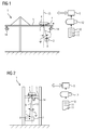
- a crane 1 for handling a load 2 has an upper load suspension point 3.
- the upper load suspension point 3, for example, as shown in the 1 and 2 be arranged on a trolley 4, which is movable on a boom 5 of the crane 1 in a traversing x.
- a cable system 6 extends to a lower load suspension point 7.
- the lower load suspension point 7 is thus connected to the upper load suspension point 3 via the cable system 6.
- the load 2 is releasably connected to the lower load suspension point 7. If and as long as the load 2 is connected to the lower load suspension point 7, the load 2 will collapse raised and lowered with the lower load suspension point 7.
- the load 2 has a center of gravity 8.
- the center of gravity 8 of the load 2 lies below the lower load suspension point 7.
- the center of gravity 8 thus has a distance h from the lower load suspension point 7.
- the crane 1 is controlled by a control device 9.
- the control device 9 is usually designed as a software programmable control device.
- the design of the control device 9 is effected in this case by a computer program 10, with which the control device 9 is programmed.
- the computer program 10 comprises machine code 11 which can be processed by the control device 9.
- the execution of the machine code 11 by the control device 9 causes the control device 9 to operate the crane 1.
- the processing of the machine code 11 by the control device 9 initially causes the normal handling of loads 2, as in the prior art also. Furthermore, the processing of the machine code 11 by the control device 9, however, additionally causes the control device 9 to operate the crane 1 during the turning over of the load 2 according to a method for influencing a pendulum movement of the load 2, which will be explained in more detail below.
- the computer program 10 can be supplied to the control device 9 in any desired manner. As shown in the 1 and 2 the supply of the computer program 10 via a data carrier 12, on which the computer program 10 in machine-readable form - for example, in electronic form - is deposited.
- the disk 12, as shown in the 1 and 2 be designed for example as a USB memory stick. However, other embodiments are possible as well.
- the pendulum movement is on a vertical Level 13 related.
- the vertical plane 13 contains the upper load suspension point 3.
- the pendulum movement can be described by a deflection angle ⁇ of the cable system 6 from the vertical about the upper load suspension point 3, wherein the deflection angle ⁇ varies with time.
- Such a pendulum motion should be attenuated or suppressed according to the invention.
- the load 2 oscillates in the travel direction x.
- the vertical plane 13 corresponding to the mark in FIG. 2 parallel to the travel direction x.
- the load 2 as shown in FIG. 2 orthogonal to the travel direction x commutes.
- the vertical plane 13 corresponding to the mark in FIG. 1 orthogonal to the travel direction x (so-called side sway).
- This latter case represents the rule of the application of the present invention.
- the former case is also possible.
- the two cases can be considered independently. Even in the event that both oscillations occur and the oscillations have a phase offset relative to each other, the two oscillations can thus be damped independently.
- the crane 1 has a detection device 14.
- the detection device 14 By means of the detection device 14, the deflection angle ⁇ of the cable system 6 can be detected.
- a time derivative of the deflection angle ⁇ can be detected, for example the first time derivative (angular velocity) and / or the second time derivative (angular acceleration).
- the detection device 14 is designed as a camera system. This embodiment is currently preferred. In principle, however, the detection device 14 can be designed as desired, provided that it has the required functionality.
- the detection device 14 is connected to the control device 9 in terms of data technology.
- the detected deflection angle ⁇ and / or the detected time derivative of the deflection angle ⁇ are supplied to the control device 9.
- the control device 9 takes the detected deflection angle ⁇ and / or the detected time derivative of the deflection angle ⁇ in accordance with FIG. 3 in a step S1 opposite.
- a step S2 the control device 9 determines a manipulated variable S for an actuating device 15 (see FIG FIGS. 5 and 6 ).
- the control device 9 controls the adjusting device 15 in accordance with the determined manipulated variable S.
- the manipulated variable S acts on the load 2.
- a tilting moment M is introduced into the load 2 by means of the adjusting device 15 around the lower load suspension point 7.
- the determination of the manipulated variable S takes place in such a way that the overturning moment M introduced into the load 2 counteracts the pendulum movement of the load 2 about the upper load suspension point 3.
- the load 2 has a mass m.
- the cable system 6 also has, as already mentioned, an effective cable length 1. Finally, the center of gravity 8 of the load 2 from the lower load suspension point 7 on the distance h.
- J ⁇ corresponds to the effective moment of inertia of the load 2 about the upper load suspension point 3.
- m is the mass of the load 2
- g is the gravitational acceleration.
- J ⁇ corresponds to the effective moment of inertia of the load 2 around the lower load suspension point 7.
- J ⁇ m ⁇ l ⁇ l + / 2 H
- J ⁇ m ⁇ H 2 3 + L 2 12 + l / 2 H
- Equation 5 D represents a freely selectable attenuation.
- the first time derivative is also referred to in the usual way with a dot.
- ⁇ ⁇ is the natural frequency of the vibration.
- the deflection angle ⁇ of the load 2 about the upper load suspension point 3 their time derivatives
- the deflection ⁇ of the load 2 about the lower load suspension point 7 and their time derivatives are all Known sizes.
- FIG. 7 shows the corresponding structure of the controlled system and the determination of the overturning moment M.
- the reference numeral 16 integrators which integrate the respective input quantity supplied to them over time.
- Reference numeral 17 designates multipliers which multiply the respective input quantity supplied to them by a factor. The factor that is multiplied by is in FIG. 7 indicated in the respective multiplier 17.
- node points are designated, at which the respective node 18 supplied quantities are added or - if a minus sign is noted - are subtracted.
- the L-shaped part of FIG. 7 describes the controlled system, that is, the pendulum movement performed by the load 2 around the upper load suspension point 3.
- the rectangular part describes the determination of the overturning moment M or the associated acceleration of the deflection ⁇ .
- the effective rope length 1 is constant over time. However, it is also possible that the effective rope length 1 varies over time. In this case, it is only necessary to consider the factors of the multipliers 17 of FIG. 7 to update continuously. This is easily realizable.
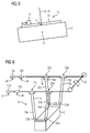
- the adjusting device 15, by means of which the tilting moment M is introduced into the load 2, can be configured as needed.
- the adjusting device 15 may be arranged in particular at the lower Lastauf rehabilitationtician 7 and directly - on-site - bring the overturning moment M in the load 2.
- actuator 15 in this Case as shown in FIG. 5 be designed as a linear drive 20, by means of which a mass 21 is moved linearly.
- the cable system 6 as shown in FIG. 6 four cables 19.
- one of the cables 19 extends from a respective upper corner point 22 arranged in the region of the upper load suspension point 3 to a respective lower corner point 23 arranged in the region of the lower load suspension point 7.
- the cables 19, the upper corner points 22 and lower vertices 23 are in FIG. 6 supplemented by a respective letter a to d, in order to be able to differentiate them if necessary.
- the adjusting device 15 for introducing the tilting moment M in the load 2 causes in this case - ie in the case of an existing four ropes 19 cable system 6 - a length adjustment of the ropes 19 relative to each other.
- the effective cable lengths la, lb can be varied by a change in length ⁇ l and / or the effective cable lengths lc, ld can be varied by a change in length - ⁇ 1.
- both measures are taken simultaneously.
- the adjusting device 15 is driven such that it extends and shortens each of two of the four cables 19.
- the upper corner points 22 an upper rectangle with an upper length Lo and an upper width Bo.
- the lower corner points 23 define a lower rectangle with a lower length Lu and a lower width Bu.
- the upper length Lo is larger than the lower length Lu.
- the upper width Bo is preferably greater than the lower width Bu.
- the cables 19a to 19d can be assigned individually controllable hoists, by means of which both the lifting movement of the load 2 and the individual Length adjustment of the cables 19 is realized.
- the hoists in their entirety correspond to the adjusting device 15.
- the ropes 19 as shown in FIG. 6 in addition to the adjusting device 15 assigned a hoist 24, by means of which the effective length of the ropes 19 19 is uniformly changed.
- This embodiment has the advantage that the adjusting device 15 only has to allow a small travel.
- the adjusting device 15 in the case of the embodiment according to FIG. 5 be formed for example as a group of electrically operated winches.
- the present invention has many advantages. In particular, it is possible in a simple manner to dampen pendulum movements of the load 2 around the upper load suspension point 3 both in the travel direction x of the trolley 4 and transversely thereto. In particular, in the case of a cable system 6 with four cables 19, an active damping of the pendulum movement of the load 2 is possible even without arranged in the region of the lower Lastauf vonticians 7 adjusting device. The scheme continues to prove very robust.
Landscapes
- Engineering & Computer Science (AREA)
- Mechanical Engineering (AREA)
- Control And Safety Of Cranes (AREA)
Abstract
Ein Kran (1) zum Umschlagen einer Last (2) weist einen unteren Lastaufhängepunkt (7) und einen oberen Lastaufhängepunkt (3) auf, die über ein Seilsystem (6) miteinander verbunden sind. Ein Schwerpunkt (8) einer mit dem unteren Lastaufhängepunkt (7) verbundenen Last (2) liegt unterhalb des unteren Lastaufhängepunkts (7). Mittels einer Erfassungseinrichtung (14) wird ein Auslenkwinkel (Õ) einer Pendelbewegung und/oder eine zeitlichen Ableitung des Auslenkwinkels (Õ) der Pendelbewegung erfasst, welche die Last (2), bezogen auf eine den oberen Lastaufhängepunkt (3) enthaltende vertikale Ebene (13), um den oberen Lastaufhängepunkt (3) durchführt. Von einer Steuereinrichtung (9) wird anhand eines Stellgesetzes eine auf die Last (2) wirkende Stellgröße (S) ermittelt. Eine Stelleinrichtung (15) des Krans (1) wird von der Steuereinrichtung (9) entsprechend der ermittelten Stellgröße (S) angesteuert, so dass mittels der Stelleinrichtung (15) innerhalb der vertikalen Ebene (13) ein Kippmoment (M) um den unteren Lastaufhängepunkt (7) in die Last (2) eingebracht wird. Das in die Last (2) eingebrachte Kippmoment (M) wirkt der Pendelbewegung der Last (2) um den oberen Lastaufhängepunkt (3) entgegen.A crane (1) for handling a load (2) has a lower load suspension point (7) and an upper load suspension point (3), which are connected to each other via a cable system (6). A center of gravity (8) of a load (2) connected to the lower load suspension point (7) lies below the lower load suspension point (7). By means of a detection device (14), a deflection angle (Õ) of a pendulum movement and / or a time derivative of the deflection angle (Õ) of the pendulum motion is detected, which relates to the load (2) with respect to a vertical plane (13) containing the upper load suspension point (3) ) to perform the upper load suspension point (3). By a control device (9) on the load (2) acting control variable (S) is determined based on an actuating law. An adjusting device (15) of the crane (1) is controlled by the control device (9) according to the determined manipulated variable (S), so that by means of the adjusting device (15) within the vertical plane (13) a tipping moment (M) about the lower load suspension point (7) is introduced into the load (2). The tilting moment (M) introduced into the load (2) counteracts the pendulum movement of the load (2) about the upper load suspension point (3).
Description
Die vorliegende Erfindung betrifft ein Verfahren zur Beeinflussung einer Pendelbewegung einer mittels eines Krans umgeschlagenen Last, wobei die Last mit einem unteren Lastaufhängepunkt des Krans verbunden ist und der untere Lastaufhängepunkt über ein Seilsystem des Krans mit einem oberen Lastaufhängepunkt des Krans verbunden ist, so dass ein Schwerpunkt der Last unterhalb des unteren Lastaufhängepunkts liegt, wobei die Pendelbewegung auf eine den oberen Lastaufhängepunkt enthaltende vertikale Ebene bezogen ist.The present invention relates to a method for influencing a pendulum movement of a crane-handled load, wherein the load is connected to a lower load suspension point of the crane and the lower load suspension point is connected via a cable system of the crane with an upper load suspension point of the crane, so that a center of gravity the load is below the lower load suspension point, wherein the pendulum motion is related to a vertical plane containing the upper load suspension point.
Die vorliegende Erfindung betrifft weiterhin ein Computerprogramm für eine Steuereinrichtung eines Krans, wobei das Computerprogramm Maschinencode umfasst, der von der Steuereinrichtung abarbeitbar ist, wobei die Abarbeitung des Maschinencodes durch die Steuereinrichtung bewirkt, dass die Steuereinrichtung den Kran gemäß einem derartigen Verfahren betreibt.The present invention further relates to a computer program for a control device of a crane, the computer program comprising machine code which can be executed by the control device, wherein the execution of the machine code by the control device causes the control device to operate the crane according to such a method.
Die vorliegende Erfindung betrifft weiterhin eine Steuereinrichtung für einen Kran, wobei die Steuereinrichtung derart ausgebildet ist, insbesondere programmiert ist, dass sie den Kran gemäß einem derartigen Verfahren betreibt.The present invention further relates to a control device for a crane, wherein the control device is designed, in particular programmed, that it operates the crane according to such a method.
Die vorliegende Erfindung betrifft weiterhin einen Kran zum Umschlagen einer Last,
- wobei der Kran einen unteren Lastaufhängepunkt, einen oberen Lastaufhängepunkt und ein Seilsystem aufweist,
- wobei die Last mit dem unteren Lastaufhängepunkt verbindbar ist, so dass ein Schwerpunkt der Last unterhalb des unteren Lastaufhängepunkts liegt,
- wobei der untere Lastaufhängepunkt über das Seilsystem mit dem oberen Lastaufhängepunkt verbunden ist.
- the crane having a lower load suspension point, an upper load suspension point and a cable system,
- wherein the load is connectable to the lower load suspension point such that a center of gravity of the load is below the lower load suspension point,
- wherein the lower load suspension point is connected via the cable system to the upper load suspension point.
Zum Umschlagen von Lasten - beispielsweise von einem Schiff auf einen Lastkraftwagen oder einen Eisenbahnwaggon oder umgekehrt - werden oftmals Krane eingesetzt. Derartige Krane weisen oftmals einen im wesentlichen horizontal orientierten Ausleger auf, auf dem eine Laufkatze linear verfahrbar ist. Die Laufkatze entspricht einem oberen Lastaufhängepunkt im Sinne der vorliegenden Erfindung. Es kann ferner oftmals der Kran als Ganzes ebenfalls verfahrbar sein. Die Verfahrrichtung des Kranes als Ganzes verläuft in diesem Fall in der Regel ebenfalls horizontal und insbesondere orthogonal zur Verfahrrichtung der Laufkatze. Derartige Krane können insbesondere als Containerbrücken ausgebildet sein.For handling loads - for example from a ship to a truck or a railroad car or vice versa - cranes are often used. Such cranes often have a substantially horizontally oriented boom, on which a trolley is linearly movable. The trolley corresponds to an upper load suspension point in the sense of the present invention. Furthermore, often the crane as a whole can also be moved. The direction of travel of the crane as a whole generally runs in this case also horizontally and in particular orthogonal to the direction of travel of the trolley. Such cranes can be designed in particular as container bridges.
Zum Umschlagen der Last wird die Last an einem Aufnahmeort mit dem unteren Lastaufhängepunkt verbunden. Danach wird durch entsprechendes Verkürzen einer wirksamen Seillänge des Seilsystems die Last angehoben, durch entsprechendes Verfahren des oberen Lastaufhängepunkts vom Aufnahmeort zu einem Zielort verfahren und dort durch entsprechendes Verlängern der wirksamen Seillänge des Seilsystems abgesetzt. Während des Verfahrens vom Aufnahmeort zum Zielort sollte die Last idealerweise jederzeit vertikal unter dem oberen Lastaufhängepunkt und ebenfalls vertikal unter dem unteren Lastaufhängepunkt angeordnet sein. Oftmals führt die Last einschließlich des unteren Lastaufhängepunkts jedoch eine Pendelbewegung um den oberen Lastaufhängepunkt durch. Die Pendelbewegung ist auf eine vertikale Ebene bezogen, welche den oberen Lastaufhängepunkt enthält. Die Pendelbewegung kann durch verschiedene Ursachen angeregt werden. Eine mögliche Ursache ist die Verfahrbewegung des oberen Lastaufhängepunkts, beispielsweise der Laufkatze. In diesem Fall ist die vertikale Ebene derart orientiert, dass sie zusätzlich zur Vertikalrichtung die Verfahrrichtung der Laufkatze enthält. Alternativ kann die Pendelbewegung beispielsweise durch Seitenwind oder durch eine Verfahrbewegung des Kranes als Ganzes angeregt werden. In diesem Fall ist die vertikale Ebene derart orientiert, dass sie orthogonal zur Verfahrrichtung der Laufkatze verläuft. Diese Pendelbewegung wird in Fachkreisen als side sway bezeichnet.To load the load, the load is connected to the lower load suspension point at a pickup location. Thereafter, by appropriate shortening of an effective rope length of the cable system, the load is raised, moved by appropriate method of the upper Lastaufhängepunkts from the recording location to a destination and there discontinued by appropriately extending the effective cable length of the cable system. Ideally, during the method from the picking location to the destination, the load should always be located vertically below the upper load suspension point and also vertically below the lower load suspension point. Often, however, the load, including the lower load suspension point, oscillates about the upper load suspension point. The pendulum motion is related to a vertical plane containing the upper load suspension point. The pendulum motion can be stimulated by various causes. One possible cause is the movement of the upper Lastaufhängepunkts, for example, the trolley. In this case, the vertical plane is oriented so as to include the traveling direction of the trolley in addition to the vertical direction. Alternatively, the pendulum movement can be stimulated for example by crosswind or by a movement of the crane as a whole. In this case, the vertical plane is oriented to be orthogonal to the Traversing the trolley runs. This pendulum movement is referred to in professional circles as a side sway.
Eine Pendelbewegung wirkt sich negativ auf die Umschlagleistung aus. Beispielsweise muss nach dem Verfahren zum Zielort abgewartet werden, bis die Pendelbewegung abgeklungen ist. Alternativ muss die Pendelbewegung beispielsweise durch manuelles Eingreifen des Kranführers im Handsteuerbetrieb gedämpft werden.A pendulum movement has a negative effect on the handling capacity. For example, it is necessary to wait for the procedure to the destination until the pendulum movement has subsided. Alternatively, the pendulum movement must be damped, for example by manual intervention of the crane operator in manual control mode.
Die Aufgabe der vorliegenden Erfindung besteht darin, Möglichkeiten zu schaffen, mittels derer auf einfache und zuverlässige Weise eine automatisierte Dämpfung einer Pendelbewegung der Last möglich ist.The object of the present invention is to provide ways by which an automatic damping of a pendulum movement of the load is possible in a simple and reliable manner.
Die Aufgabe wird durch ein Verfahren mit den Merkmalen des Anspruchs 1 gelöst. Vorteilhafte Ausgestaltungen des Verfahrens sind Gegenstand der abhängigen Ansprüche 2 bis 6.The object is achieved by a method having the features of
Erfindungsgemäß wird ein Verfahren der eingangs genannten Art dadurch ausgestaltet,
- dass ein Auslenkwinkel der Pendelbewegung und/oder eine zeitliche Ableitung des Auslenkwinkels der Pendelbewegung erfasst und einer Steuereinrichtung des Krans zugeführt werden,
- dass von der Steuereinrichtung anhand eines Stellgesetzes eine auf die Last wirkende Stellgröße ermittelt wird und
- dass von der Steuereinrichtung eine Stelleinrichtung des Krans entsprechend der ermittelten Stellgröße angesteuert wird, so dass mittels der Stelleinrichtung innerhalb der vertikalen Ebene ein Kippmoment um den unteren Lastaufhängepunkt in die Last eingebracht wird, das der Pendelbewegung der Last um den oberen Lastaufhängepunkt entgegenwirkt.
- that a deflection angle of the pendulum movement and / or a time derivative of the deflection angle of the pendulum motion are detected and fed to a control device of the crane,
- in that a control variable acting on the load is determined by the control device on the basis of an actuating law and
- in that an adjusting device of the crane is controlled by the control device in accordance with the determined manipulated variable so that a tilting moment about the lower load suspension point is introduced into the load by means of the actuating device within the vertical plane, counteracting the pendulum movement of the load about the upper load suspension point.
Das erfindungsgemäße Verfahren arbeitet somit nach demselben Prinzip, mittels dessen ein Kind auf einer Schaukel schaukelt. Im Gegensatz zur normalen Vorgehensweise eines Kindes beim Schaukeln wird die Pendelbewegung bei dem erfindungsgemäßen Verfahren jedoch nicht angeregt, sondern gedämpft.The inventive method thus operates on the same principle by means of which a child swings on a swing. Unlike the normal approach of a child when rocking the pendulum motion is not excited in the inventive method, but damped.
In vielen Fällen ist der obere Lastaufhängepunkt mittels einer Laufkatze des Krans in einer Verfahrrichtung verfahrbar. Es ist möglich, dass die vertikale Ebene, auf welche die Pendelbewegung bezogen ist, parallel zu der Verfahrrichtung der Laufkatze verläuft. Bei einer Pendelbewegung in einer derartigen vertikalen Ebene stehen jedoch zusätzlich zur erfindungsgemäßen Vorgehensweise auch andere Möglichkeiten zur Verfügung, die Pendelbewegung zu dämpfen. Insbesondere kann eine Verfahrgeschwindigkeit der Laufkatze angepasst werden, um die Pendelbewegung zu dämpfen. Es ist jedoch alternativ möglich, dass die vertikale Ebene, auf welche die Pendelbewegung der Last bezogen ist, orthogonal zu der Verfahrrichtung verläuft (sogenannter side sway). In diesem Fall bietet die erfindungsgemäße Vorgehensweise erstmals die Möglichkeit, automatisiert eine derartige Pendelbewegung zu dämpfen.In many cases, the upper load suspension point by means of a trolley of the crane in a direction of travel is movable. It is possible that the vertical plane, to which the oscillating movement is related, parallel to the direction of travel of the trolley. In a pendulum motion in such a vertical plane, however, other options are available in addition to the procedure according to the invention to dampen the pendulum motion. In particular, a travel speed of the trolley can be adjusted to dampen the pendulum motion. However, it is alternatively possible for the vertical plane, to which the pendulum movement of the load is related, to be orthogonal to the direction of travel (so-called side sway). In this case, the procedure according to the invention offers for the first time the possibility of automatically damping such a pendulum motion.
Es ist möglich, dass die Stelleinrichtung am unteren Lastaufhängepunkt angeordnet ist. Beispielsweise kann der untere Lastaufhängepunkt zu diesem Zweck einen innerhalb der vertikalen Ebene im wesentlichen horizontal verfahrbaren Linearantrieb aufweisen. Die Anordnung der Stelleinrichtung am unteren Lastaufhängepunkt ist insbesondere dann sinnvoll, wenn das Seilsystem ein einziges Seil aufweist.It is possible that the adjusting device is arranged at the lower load suspension point. For example, the lower load suspension point for this purpose have a within the vertical plane substantially horizontally movable linear drive. The arrangement of the adjusting device at the lower load suspension point is particularly useful when the cable system has a single rope.
In vielen Fällen umfasst das Seilsystem vier Seile, die von einem jeweiligen im Bereich des oberen Lastaufhängepunkts angeordneten oberen Eckpunkt zu einem jeweiligen im Bereich des unteren Lastaufhängepunkts angeordneten unteren Eckpunkt verlaufen. In diesem Fall ist es möglich, dass die Stelleinrichtung zum Einbringen des Kippmoments in die Last eine Längenverstellung der Seile relativ zueinander bewirkt. Durch eine derartige Längenverstellung der Seile relativ zueinander wird die Last sozusagen schief aufgehängt. Die schiefe Aufhängung der Last muss in diesem Fall derart auf die Pendelbewegung abgestimmt werden, dass die schiefe Aufhängung der Pendelbewegung entgegenwirkt.In many cases, the cable system comprises four cables which extend from a respective upper corner point arranged in the region of the upper load suspension point to a respective lower corner point arranged in the region of the lower load suspension point. In this case, it is possible that the adjusting device for introducing the tilting moment into the load causes a length adjustment of the cables relative to each other. By such a length adjustment of the cables relative to each other, the load is suspended as it were askew. The oblique suspension of the load must be in this case on the pendulum motion be adjusted that counteracts the oblique suspension of the pendulum motion.
Die letztgenannte Vorgehensweise erfordert insbesondere bei bereits bestehenden Kranen in der Regel nur einen minimalen Modifikationsaufwand. Denn die individuelle Längenverstellbarkeit der Seile ist in der Regel bereits gegeben. Die entsprechende Funktionalität ist in Fachkreisen als so genannte TLS-Funktionalität bekannt. Die Abkürzung TLS steht für trimm - list - skew. Die TLS-Funktionalität wird im Stand der Technik jedoch nur genutzt, um im Rahmen des Verbindens der Last mit dem unteren Lastaufhängepunkt am Aufnahmeort manuell den unteren Lastaufhängepunkt exakt auf die Last abzusenken und um im Rahmen des Absetzens der Last am Zielort beim Absenken der Last die Last unmittelbar vor dem Absetzen in diesen drei Bewegungsrichtungen manuell exakt auszurichten.The latter approach usually requires only a minimum of modification effort, especially in existing cranes. Because the individual length adjustability of the ropes is usually already given. The corresponding functionality is known in professional circles as so-called TLS functionality. The abbreviation TLS stands for trimm - list - skew. The TLS functionality is used in the prior art, however, only to reduce the lower load suspension point on the load manually in the context of connecting the load with the lower Lastaufhängepunkt at the pickup and manually in the context of settling the load at the destination when lowering the load Manually align load directly before settling in these three directions of movement.
Vorzugsweise wird im Falle eines vier Seile umfassenden Seilsystems die Stelleinrichtung zum Einbringen des Kippmoments in die Last derart angesteuert, dass sie jeweils zwei der vier Seile verlängert und verkürzt. Dadurch wird die effektive Hubhöhe der Last durch die Dämpfung der Pendelbewegung nicht beeinflusst.Preferably, in the case of a cable system comprising four cables, the adjusting device for introducing the overturning moment into the load is controlled in such a way that it lengthens and shortens two of the four cables in each case. As a result, the effective lifting height of the load is not affected by the damping of the pendulum motion.
Oftmals definieren die oberen Eckpunkte ein oberes Rechteck mit einer oberen Länge und einer oberen Breite und die unteren Eckpunkte ein unteres Rechteck mit einer unteren Länge und einer unteren Breite. In diesem Fall sind in der Regel die obere Länge größer als die untere Länge und/oder die obere Breite größer als die untere Breite.Often the top corners define an upper rectangle with an upper length and an upper width and the lower corner points a lower rectangle with a lower length and a lower width. In this case, the upper length is generally greater than the lower length and / or the upper width greater than the lower width.
Vorzugsweise ist im Falle eines vier Seile umfassenden Seilsystems den Seilen zusätzlich zur Stelleinrichtung ein Hubwerk des Krans zugeordnet, mittels dessen eine wirksame Länge der Seile gleichmäßig veränderbar ist. Dadurch ist insbesondere eine voneinander unabhängige Steuerung der Hubbewegung der Last einerseits und der Verkippung der Last zur Dämpfung der Pendelbewegung andererseits realisierbar.Preferably, in the case of a cable system comprising four ropes, the ropes are assigned, in addition to the adjusting device, a lifting mechanism of the crane by means of which an effective length of the ropes can be changed uniformly. As a result, in particular independent control of the lifting movement of the load on the one hand and the tilting of the load for damping the pendulum motion on the other hand can be realized.
Die Aufgabe wird weiterhin durch ein Computerprogramm mit den Merkmalen des Anspruchs 7 gelöst. Erfindungsgemäß bewirkt die Abarbeitung des Maschinencodes durch die Steuereinrichtung, dass die Steuereinrichtung den Kran gemäß einem erfindungsgemäßen Verfahren betreibt.The object is further achieved by a computer program having the features of
Die Aufgabe wird weiterhin durch eine Steuereinrichtung mit den Merkmalen des Anspruchs 8 gelöst. Erfindungsgemäß ist die Steuereinrichtung derart ausgebildet, insbesondere programmiert, dass sie den Kran gemäß einem erfindungsgemäßen Verfahren betreibt.The object is further achieved by a control device with the features of
Die Aufgabe wird weiterhin durch einen Kran mit den Merkmalen des Anspruchs 9 gelöst. Vorteilhafte Ausgestaltungen des Krans sind Gegenstand der abhängigen Ansprüche 10 bis 14.The object is further achieved by a crane having the features of
Erfindungsgemäß wird ein Kran der eingangs genannten Art dadurch ausgestaltet,
- dass der Kran eine Erfassungseinrichtung zur Erfassung eines Auslenkwinkels einer Pendelbewegung und/oder einer zeitlichen Ableitung des Auslenkwinkels der Pendelbewegung aufweist, welche die Last, bezogen auf eine den oberen Lastaufhängepunkt enthaltende vertikale Ebene, um den oberen Lastaufhängepunkt durchführt,
- dass der Kran eine Stelleinrichtung aufweist, mittels derer in die Last innerhalb der vertikalen Ebene ein Kippmoment einbringbar ist,
- dass der Kran eine Steuereinrichtung aufweist, welcher der erfasste Auslenkwinkel und/oder die erfasste zeitliche Ableitung des Auslenkwinkels zugeführt werden, von der anhand eines Stellgesetzes eine Stellgröße der Stelleinrichtung ermittelt wird und von der die Stelleinrichtung entsprechend der ermittelten Stellgröße angesteuert wird, und
- dass die Stellgröße von der Steuereinrichtung derart ermittelt wird, dass das in die Last eingebrachte Kippmoment der Pendelbewegung der Last um den oberen Lastaufhängepunkt entgegenwirkt.
- the crane comprises a detection device for detecting a deflection angle of a pendulum movement and / or a time derivative of the deflection angle of the pendulum movement, which carries out the load relative to a vertical plane containing the upper load suspension point, around the upper load suspension point,
- that the crane has an adjusting device by means of which a tilting moment can be introduced into the load within the vertical plane,
- that the crane has a control device to which the detected deflection angle and / or the detected time derivative of the deflection angle are supplied, from which a manipulated variable of the actuating device is determined by means of an actuating law and by which the actuating device is controlled according to the determined manipulated variable, and
- that the manipulated variable is determined by the control device such that the overturning moment introduced into the load counteracts the pendulum movement of the load about the upper load suspension point.
Die vorteilhaften Ausgestaltungen des Krans korrespondieren im wesentlichen mit denen des Verfahrens, so dass von detaillierten Erläuterungen dieser Ausgestaltungen abgesehen werden kann.The advantageous embodiments of the crane correspond substantially with those of the method, so that can be dispensed with detailed explanations of these embodiments.
Die oben beschriebenen Eigenschaften, Merkmale und Vorteile dieser Erfindung sowie die Art und Weise, wie diese erreicht werden, werden klarer und deutlicher verständlich im Zusammenhang mit der folgenden Beschreibung der Ausführungsbeispiele, die in Verbindung mit den Zeichnungen näher erläutert werden. Hierbei zeigen in schematischer Darstellung:
- FIG 1
- einen Kran von der Seite,
- FIG 2
- den Kran von
FIG 1 von vorne, - FIG 3
- ein Ablaufdiagramm,
- FIG 4
- eine pendelnde Last,
- FIG 5
- eine Last und einen unteren Lastaufhängepunkt,
- FIG 6
- eine Last, einen oberen und einen unteren Lastaufhängepunkt und ein Seilsystem,
- FIG 7
- ein Blockschaltbild einer Regelstrecke einschließlich der zugehörigen Regelung und
- FIG 8
- eine Ergänzung zu
FIG 6 .
- FIG. 1
- a crane from the side,
- FIG. 2
- the crane of
FIG. 1 from the front, - FIG. 3
- a flow chart,
- FIG. 4
- a swinging load,
- FIG. 5
- a load and a lower load suspension point,
- FIG. 6
- a load, an upper and a lower load suspension point and a cable system,
- FIG. 7
- a block diagram of a controlled system including the associated control and
- FIG. 8
- an addition to
FIG. 6 ,
Gemäß den
Der Kran 1 wird von einer Steuereinrichtung 9 gesteuert. Die Steuereinrichtung 9 ist in der Regel als softwareprogrammierbare Steuereinrichtung ausgebildet. Die Ausbildung der Steuereinrichtung 9 wird in diesem Fall durch ein Computerprogramm 10 bewirkt, mit dem die Steuereinrichtung 9 programmiert ist. Das Computerprogramm 10 umfasst Maschinencode 11, der von der Steuereinrichtung 9 abarbeitbar ist. Die Abarbeitung des Maschinencodes 11 durch die Steuereinrichtung 9 bewirkt, dass die Steuereinrichtung 9 den Kran 1 betreibt.The
Die Abarbeitung des Maschinencodes 11 durch die Steuereinrichtung 9 bewirkt zunächst den normalen Umschlag von Lasten 2, wie im Stand der Technik auch. Weiterhin bewirkt die Abarbeitung des Maschinencodes 11 durch die Steuereinrichtung 9 jedoch zusätzlich das die Steuereinrichtung 9 den Kran 1 während des Umschlagens der Last 2 gemäß einem Verfahren zur Beeinflussung einer Pendelbewegung der Last 2 betreibt, das nachstehend näher erläutert wird.The processing of the
Das Computerprogramm 10 kann der Steuereinrichtung 9 auf beliebige Weise zugeführt werden. Gemäß der Darstellung in den
Während des Umschlagens der Last 2 kann es geschehen, dass die Last 2 eine Pendelbewegung um den oberen Lastaufhängepunkt 3 durchführt. Die Pendelbewegung ist auf eine vertikale Ebene 13 bezogen. Die vertikale Ebene 13 enthält den oberen Lastaufhängepunkt 3. Die Pendelbewegung kann durch einen Auslenkwinkel ϕ des Seilsystems 6 aus der Vertikalen um den oberen Lastaufhängepunkt 3 beschrieben werden, wobei der Auslenkwinkel ϕ mit der Zeit variiert. Eine derartige Pendelbewegung soll erfindungsgemäß gedämpft bzw. unterdrückt werden.During the turning over of the
Gemäß der Darstellung in
Der Kran 1 weist eine Erfassungseinrichtung 14 auf. Mittels der Erfassungseinrichtung 14 kann der Auslenkwinkel ϕ des Seilsystems 6 erfasst werden. Alternativ oder zusätzlich kann mittels der Erfassungseinrichtung 14 eine zeitliche Ableitung des Auslenkwinkels ϕ erfasst werden, beispielsweise die erste zeitliche Ableitung (Winkelgeschwindigkeit) und/oder die zweite zeitliche Ableitung (Winkelbeschleunigung). Gemäß der Darstellung in den
Die Erfassungseinrichtung 14 ist mit der Steuereinrichtung 9 datentechnisch verbunden. Insbesondere werden der erfasste Auslenkwinkels ϕ und/oder die erfasste zeitliche Ableitung des Auslenkwinkels ϕ der Steuereinrichtung 9 zugeführt. Die Steuereinrichtung 9 nimmt den erfassten Auslenkwinkels ϕ und/oder die erfasste zeitliche Ableitung des Auslenkwinkels ϕ gemäß
In einem Schritt S2 ermittelt die Steuereinrichtung 9 anhand eines Stellgesetzes - das Stellgesetz wird später noch detailliert erläutert werden - eine Stellgröße S für eine Stelleinrichtung 15 (siehe
Nachfolgend wird in Verbindung mit
Die Last 2 weist eine Masse m auf. Das Seilsystem 6 weist ferner, wie bereits erwähnt, eine wirksame Seillänge 1 auf. Schließlich weist der Schwerpunkt 8 der Last 2 vom unteren Lastaufhängepunkt 7 den Abstand h auf.The
Wenn die Last 2 zusätzlich zur Pendelbewegung um den oberen Lastaufhängepunkt 3 um den unteren Lastaufhängepunkt 7 pendeln kann, sind diese beiden Pendelbewegungen miteinander gekoppelt. Wenn die Auslenkung der Last 2 aus einer Ruhelage um den unteren Lastaufhängepunkt 7 - genauer: des Schwerpunkts 8 der Last 2 aus einer Vertikalen V durch den unteren Lastaufhängepunkt 7 - mit β bezeichnet wird, gehorchen die beiden gekoppelten Pendelbewegungen - zumindest für kleine Pendelbewegungen - näherungsweise der Beziehung ![]()
![]()
In obiger Formel ist in üblicher Weise mit 2 Punkten die zweite zeitliche Ableitung bezeichnet. Jϕ entspricht dem wirksamen Trägheitsmoment der Last 2 um den oberen Lastaufhängepunkt 3. m ist die Masse der Last 2, g die Erdbeschleunigung. Jβ entspricht dem wirksamen Trägheitsmoment der Last 2 um den unteren Lastaufhängepunkt 7. Für den Fall eines Containers, der in Vertikalrichtung eine Höhe H und in der Horizontalrichtung der betrachteten Pendelbewegung eine Längserstreckung L aufweist, ergeben sich die beiden Trägheitsmomente Jϕ und Jβ zu ![]()

![]()
Hierbei wurde angenommen, dass der untere Lastaufhängepunkt 7 sich mittig an der Oberseite des Containers befindet.It was assumed that the lower
Gleichung 1 kann umgeformt werden zu 
Eine gedämpfte Schwingung der Last 2 um den oberen Lastaufhängepunkt 3 hat allgemein die Form 
In Gleichung 5 bedeutet D eine frei wählbare Dämpfung. In obiger Formel ist weiterhin in üblicher Weise mit einem Punkt die erste zeitliche Ableitung bezeichnet. ωϕ ist die Eigenfrequenz der Schwingung.In
Durch Vergleich der beiden Gleichungen 4 und 5 ergibt sich somit zum einen die Eigenfrequenz ωϕ der Schwingung zu 
Konkret für den Fall eines Containers ergibt sich 
Zum anderen sind die Dämpfung D der Pendelbewegung der Last 2 um den oberen Lastaufhängepunkt 3 und die Schwingung der Last 2 um den unteren Lastaufhängepunkt 7 durch die Beziehung 
Somit ergibt sich bei gewünschter Dämpfung D das Stellgesetz zu 
Die Beschleunigung der Auslenkung β ist über das Trägheitsmoment Jβ mit dem erforderlichen Kippmoment M gekoppelt: 
Es ist möglich, dass die wirksame Seillänge 1 zeitlich konstant ist. Es ist jedoch ebenso möglich, dass die wirksame Seillänge 1 zeitlich variiert. In diesem Fall ist es lediglich erforderlich, die Faktoren der Multiplizierer 17 von
Die Stelleinrichtung 15, mittels derer das Kippmoment M in die Last 2 eingebracht wird, kann nach Bedarf ausgestaltet sein. In dem in
Oftmals umfasst das Seilsystem 6 gemäß der Darstellung in
In der Regel definieren entsprechend der Darstellung in
Um eine individuelle Verstellung der wirksamen Seillängen la bis ld zu ermöglichen, können den Seilen 19a bis 19d individuell ansteuerbare Hubwerke zugeordnet sein, mittels derer sowohl die Hubbewegung der Last 2 als auch die individuelle Längenverstellung der Seile 19 realisiert wird. In diesem Fall entsprechen die Hubwerke in ihrer Gesamtheit der Stelleinrichtung 15. Vorzugsweise ist den Seilen 19 jedoch entsprechend der Darstellung in
Zusammengefasst betrifft die vorliegende Erfindung somit folgenden Sachverhalt:
Ein Kran 1 zum Umschlagen einer Last 2 weist einen unteren Lastaufhängepunkt 7 und einen oberen Lastaufhängepunkt 3 auf, dieüber ein Seilsystem 6 miteinander verbunden sind.Ein Schwerpunkt 8 einer mitdem unteren Lastaufhängepunkt 7 verbundenen Last 2 liegt unterhalb des unteren Lastaufhängepunkts 7.Mittels einer Erfassungseinrichtung 14 wird ein Auslenkwinkels ϕ einer Pendelbewegung und/oder eine zeitlichen Ableitung des Auslenkwinkels ϕ der Pendelbewegung erfasst, welche die Last 2, bezogen auf eineden oberen Lastaufhängepunkt 3 enthaltende vertikale Ebene 13, umden oberen Lastaufhängepunkt 3 durchführt.Von einer Steuereinrichtung 9 wird anhand eines Stellgesetzes eine auf die Last 2 wirkende Stellgröße S ermittelt.Eine Stelleinrichtung 15 desKrans 1 wirdvon der Steuereinrichtung 9 entsprechend der ermittelten Stellgröße S angesteuert, so dass mittels der Stelleinrichtung 15 innerhalb der vertikalen Ebene 13 ein Kippmoment M umden unteren Lastaufhängepunkt 7 in die Last 2 eingebracht wird. Das in die Last 2 eingebrachte Kippmoment M wirkt der Pendelbewegung der Last 2 umden oberen Lastaufhängepunkt 3 entgegen.
- A
crane 1 for handling aload 2 has a lowerload suspension point 7 and an upperload suspension point 3, which are connected to each other via acable system 6. A center ofgravity 8 of aload 2 connected to the lowerload suspension point 7 lies below the lowerload suspension point 7. By means of adetection device 14, a deflection angle φ of a pendulum motion and / or a time derivative of the deflection angle φ of the pendulum motion is detected, which is theload 2 with respect to a the upperload suspension point 3 containingvertical plane 13 to the upperload suspension point 3 performs. By acontrol device 9 is determined by an actuating law acting on theload 2 manipulated variable S.An adjusting device 15 of thecrane 1 is controlled by thecontrol device 9 according to the determined manipulated variable S, so that by means of the adjustingdevice 15 within thevertical plane 13, a tilting moment M to the lowerload suspension point 7 in the load. 2 is introduced. The tilting moment M introduced into theload 2 counteracts the pendulum movement of theload 2 about the upperload suspension point 3.
Die vorliegende Erfindung weist viele Vorteile auf. Insbesondere ist es auf einfache Weise möglich, Pendelbewegungen der Last 2 um den oberen Lastaufhängepunkt 3 sowohl in Verfahrrichtung x der Laufkatze 4 als auch quer dazu zu dämpfen. Insbesondere im Falle eines Seilsystems 6 mit vier Seilen 19 ist eine aktive Dämpfung der Pendelbewegung der Last 2 auch ohne im Bereich des unteren Lastaufhängepunkts 7 angeordnete Stelleinrichtung möglich. Die Regelung erweist sich weiterhin als sehr robust.The present invention has many advantages. In particular, it is possible in a simple manner to dampen pendulum movements of the
Obwohl die Erfindung im Detail durch das bevorzugte Ausführungsbeispiel näher illustriert und beschrieben wurde, so ist die Erfindung nicht durch die offenbarten Beispiele eingeschränkt und andere Variationen können vom Fachmann hieraus abgeleitet werden, ohne den Schutzumfang der Erfindung zu verlassen.Although the invention has been further illustrated and described in detail by the preferred embodiment, the invention is not limited by the disclosed examples, and other variations can be derived therefrom by those skilled in the art without departing from the scope of the invention.
Claims (14)
dadurch gekennzeichnet,
dass der obere Lastaufhängepunkt (3) mittels einer Laufkatze (4) des Krans (1) in einer Verfahrrichtung (x) verfahrbar ist und dass die vertikale Ebene (13), auf welche die Pendelbewegung der Last (2) bezogen ist, orthogonal zu der Verfahrrichtung (x) der Laufkatze (4) verläuft.Method according to claim 1,
characterized,
in that the upper load suspension point (3) can be moved in a travel direction (x) by means of a trolley (4) of the crane (1) and that the vertical plane (13) to which the pendulum movement of the load (2) is related is orthogonal to the Traverse direction (x) of the trolley (4) extends.
dadurch gekennzeichnet,
dass die Stelleinrichtung (15) am unteren Lastaufhängepunkt (7) angeordnet ist.Method according to claim 1 or 2,
characterized,
that the actuating device (15) is arranged at the lower Lastaufhängepunkt (7).
dadurch gekennzeichnet,
dass das Seilsystem (6) vier Seile (19) umfasst, die von einem jeweiligen im Bereich des oberen Lastaufhängepunkts (3) angeordneten oberen Eckpunkt (22) zu einem jeweiligen im Bereich des unteren Lastaufhängepunkts (7) angeordneten unteren Eckpunkt (23) verlaufen, und dass die Stelleinrichtung (15) zum Einbringen des Kippmoments (M) in die Last (2) eine Längenverstellung (δl) der Seile (19) relativ zueinander bewirkt.Method according to claim 1 or 2,
characterized,
that the cable system (6) comprises four ropes (19) arranged from a respective region of the upper Lastaufhängepunkts (3) the upper vertex (22) arranged to a respective in the region of the lower Lastaufhängepunkts (7) lower corner point (23) extend, and that the adjusting device (15) for introducing the tilting moment (M) in the load (2) causes a length adjustment (δl) of the cables (19) relative to each other.
dadurch gekennzeichnet,
dass die Stelleinrichtung (15) zum Einbringen des Kippmoments (M) in die Last (2) derart angesteuert wird, dass sie jeweils zwei der vier Seile (19) verlängert und verkürzt.Method according to claim 4,
characterized,
in that the adjusting device (15) for introducing the tilting moment (M) into the load (2) is actuated in such a way that it lengthens and shortens two of the four cables (19).
dadurch gekennzeichnet,
dass den Seilen (19) zusätzlich zur Stelleinrichtung (15) ein Hubwerk (24) des Krans (1) zugeordnet ist, mittels dessen eine wirksame Länge (1) der Seile (19) gleichmäßig veränderbar ist.Method according to claim 4 or 5,
characterized,
that the ropes (19) in addition to the adjusting device (15) a lifting mechanism (24) of the crane (1) is associated, by means of which an effective length (1) of the cables (19) is uniformly changed.
dadurch gekennzeichnet,
dass der Kran eine Laufkatze (4) aufweist, mittels derer der obere Lastaufhängepunkt (3) in einer Verfahrrichtung (x) verfahrbar ist und dass die vertikale Ebene (13), auf welche die Pendelbewegung der Last (2) bezogen ist, orthogonal zu der Verfahrrichtung (x) der Laufkatze (4) verläuft.Crane according to claim 9,
characterized,
in that the crane has a trolley (4), by means of which the upper load suspension point (3) in a travel direction (x) is movable and that the vertical plane (13), to which the oscillating movement of the load (2) is related, orthogonal to the direction of travel (x) of the trolley (4).
dadurch gekennzeichnet,
dass die Stelleinrichtung (15) am unteren Lastaufhängepunkt (7) angeordnet ist.Crane according to claim 9 or 10,
characterized,
that the actuating device (15) is arranged at the lower Lastaufhängepunkt (7).
dadurch gekennzeichnet,
dass das Seilsystem (6) vier Seile (19) umfasst, die von einem jeweiligen im Bereich des oberen Lastaufhängepunkts (3) angeordneten oberen Eckpunkt (22) zu einem jeweiligen im Bereich des unteren Lastaufhängepunkts (7) angeordneten unteren Eckpunkt (23) verlaufen, und dass die Stelleinrichtung (15) zum Einbringen des Kippmoments (M) in die Last (2) eine Längenverstellung (δl) der Seile (19) relativ zueinander bewirkt.Crane according to claim 9 or 10,
characterized,
that the cable system (6) comprises four ropes (19) arranged from a respective region of the upper Lastaufhängepunkts (3) the upper vertex (22) arranged to a respective in the region of the lower Lastaufhängepunkts (7) lower corner point (23) extend, and that the adjusting device (15) for introducing the tilting moment (M) in the load (2) causes a length adjustment (δl) of the cables (19) relative to each other.
dadurch gekennzeichnet,
dass die Stelleinrichtung (15) zum Einbringen des Kippmoments (M) in die Last (2) derart angesteuert wird, dass sie jeweils zwei der vier Seile (19) verlängert und verkürzt.Crane according to claim 12,
characterized,
in that the adjusting device (15) for introducing the tilting moment (M) into the load (2) is actuated in such a way that it lengthens and shortens two of the four cables (19).
dadurch gekennzeichnet,
dass den Seilen (19) zusätzlich zur Stelleinrichtung (15) ein Hubwerk (24) des Krans (1) zugeordnet ist, mittels dessen eine wirksame Länge (1) der Seile (19) gleichmäßig veränderbar ist.Crane according to claim 12 or 13,
characterized,
that the ropes (19) in addition to the adjusting device (15) a lifting mechanism (24) of the crane (1) is associated, by means of which an effective length (1) of the cables (19) is uniformly changed.
Priority Applications (1)
| Application Number | Priority Date | Filing Date | Title |
|---|---|---|---|
| EP14153004.8A EP2902356B1 (en) | 2014-01-29 | 2014-01-29 | Crane with active damping of pendular movements of loads |
Applications Claiming Priority (1)
| Application Number | Priority Date | Filing Date | Title |
|---|---|---|---|
| EP14153004.8A EP2902356B1 (en) | 2014-01-29 | 2014-01-29 | Crane with active damping of pendular movements of loads |
Publications (2)
| Publication Number | Publication Date |
|---|---|
| EP2902356A1 true EP2902356A1 (en) | 2015-08-05 |
| EP2902356B1 EP2902356B1 (en) | 2016-03-23 |
Family
ID=50000913
Family Applications (1)
| Application Number | Title | Priority Date | Filing Date |
|---|---|---|---|
| EP14153004.8A Active EP2902356B1 (en) | 2014-01-29 | 2014-01-29 | Crane with active damping of pendular movements of loads |
Country Status (1)
| Country | Link |
|---|---|
| EP (1) | EP2902356B1 (en) |
Cited By (3)
| Publication number | Priority date | Publication date | Assignee | Title |
|---|---|---|---|---|
| EP3326957A1 (en) | 2016-11-23 | 2018-05-30 | Siemens Aktiengesellschaft | Operating method for a crane |
| EP3453669A1 (en) | 2017-09-08 | 2019-03-13 | Siemens Aktiengesellschaft | Control equipment for a hoisting gear and method for operating the same |
| EP4174013A1 (en) | 2021-10-28 | 2023-05-03 | Siemens Aktiengesellschaft | Method for moving a load with a crane |
Citations (3)
| Publication number | Priority date | Publication date | Assignee | Title |
|---|---|---|---|---|
| DE4325946A1 (en) * | 1993-08-02 | 1995-02-09 | Fraunhofer Ges Forschung | Damping and positioning device for active damping of the swaying of loads suspended on cranes |
| EP0841296A1 (en) * | 1996-11-07 | 1998-05-13 | Ishikawajima-Harima Jukogyo Kabushiki Kaisha | Container crane |
| JP2010247928A (en) * | 2009-04-14 | 2010-11-04 | Toshiba Corp | Damping device of hoisted load |
-
2014
- 2014-01-29 EP EP14153004.8A patent/EP2902356B1/en active Active
Patent Citations (3)
| Publication number | Priority date | Publication date | Assignee | Title |
|---|---|---|---|---|
| DE4325946A1 (en) * | 1993-08-02 | 1995-02-09 | Fraunhofer Ges Forschung | Damping and positioning device for active damping of the swaying of loads suspended on cranes |
| EP0841296A1 (en) * | 1996-11-07 | 1998-05-13 | Ishikawajima-Harima Jukogyo Kabushiki Kaisha | Container crane |
| JP2010247928A (en) * | 2009-04-14 | 2010-11-04 | Toshiba Corp | Damping device of hoisted load |
Cited By (5)
| Publication number | Priority date | Publication date | Assignee | Title |
|---|---|---|---|---|
| EP3326957A1 (en) | 2016-11-23 | 2018-05-30 | Siemens Aktiengesellschaft | Operating method for a crane |
| EP3453669A1 (en) | 2017-09-08 | 2019-03-13 | Siemens Aktiengesellschaft | Control equipment for a hoisting gear and method for operating the same |
| WO2019048401A1 (en) | 2017-09-08 | 2019-03-14 | Siemens Aktiengesellschaft | Controller for a lifting device, and method for operating same |
| US11577939B2 (en) | 2017-09-08 | 2023-02-14 | Siemens Aktiengesellschaft | Controller for a lifting device, and method for operating same |
| EP4174013A1 (en) | 2021-10-28 | 2023-05-03 | Siemens Aktiengesellschaft | Method for moving a load with a crane |
Also Published As
| Publication number | Publication date |
|---|---|
| EP2902356B1 (en) | 2016-03-23 |
Similar Documents
| Publication | Publication Date | Title |
|---|---|---|
| EP3649072B1 (en) | Crane and method for controlling such a crane | |
| EP2272784B1 (en) | Crane for covering a load suspended on a load rope | |
| WO2020001991A1 (en) | Crane and method for controlling such a crane | |
| DE4208717C2 (en) | Control method for a crane | |
| EP3409636B1 (en) | Method for damping torsional vibrations of a load-bearing element of a lifting device | |
| DE102017112765A1 (en) | Method and device for lifting a load | |
| EP4013713B1 (en) | Crane and method for controlling such a crane | |
| DE102010023228B4 (en) | stabilizing device | |
| EP2878566B1 (en) | Method for influencing a movement of a load lifted by a crane | |
| DE102015100669A1 (en) | ANTI-PENDULUM CONTROL PROCEDURE WITH ADJUSTABLE SUPPORT FOR THE TRANSPORT OF AN ANCHORED LOAD | |
| DE102016004350A1 (en) | Crane and method for controlling such a crane | |
| DE102006015359B4 (en) | Operating method for a system with a mechanically movable element and data carrier and control device for implementing such an operating method | |
| EP2902356B1 (en) | Crane with active damping of pendular movements of loads | |
| EP1722197A2 (en) | Method and device for representing the location and the movement state of a load capable of oscillating | |
| EP3653562A1 (en) | Method and oscillating regulator for regulating oscillations of an oscillatory technical system | |
| EP2987759B1 (en) | Crane with defined oscillating motion when a destination is reached | |
| DE4395770B4 (en) | Method for the control or regulation of a harmonically oscillating load | |
| DE1431907A1 (en) | Automatic motion control for cranes or the like. | |
| EP1834920B1 (en) | Method for automatic handling of a crane load with sway damping and path control | |
| DE10029579A1 (en) | Method for orientating a load in crane equipment uses slewing gear between a cable and a load to rotate the load suspended on cables at a defined absolute angle. | |
| DE102012106233B4 (en) | pendulum indicator | |
| DE102014012457A1 (en) | Automatic erection of a crane | |
| DE4025749A1 (en) | Automatic operation of revolving crane without load swings - involves controlled timing of grab acceleration and retardation adjusted to period of natural frequency of oscillation | |
| EP2977343B1 (en) | Crane with active damping of pendular movements of loads | |
| DE102005002192B4 (en) | Method for operating a crane installation, in particular a container crane, and crane installation, in particular a container crane |
Legal Events
| Date | Code | Title | Description |
|---|---|---|---|
| PUAI | Public reference made under article 153(3) epc to a published international application that has entered the european phase |
Free format text: ORIGINAL CODE: 0009012 |
|
| 17P | Request for examination filed |
Effective date: 20141106 |
|
| AK | Designated contracting states |
Kind code of ref document: A1 Designated state(s): AL AT BE BG CH CY CZ DE DK EE ES FI FR GB GR HR HU IE IS IT LI LT LU LV MC MK MT NL NO PL PT RO RS SE SI SK SM TR |
|
| AX | Request for extension of the european patent |
Extension state: BA ME |
|
| GRAP | Despatch of communication of intention to grant a patent |
Free format text: ORIGINAL CODE: EPIDOSNIGR1 |
|
| INTG | Intention to grant announced |
Effective date: 20150915 |
|
| GRAS | Grant fee paid |
Free format text: ORIGINAL CODE: EPIDOSNIGR3 |
|
| GRAA | (expected) grant |
Free format text: ORIGINAL CODE: 0009210 |
|
| AK | Designated contracting states |
Kind code of ref document: B1 Designated state(s): AL AT BE BG CH CY CZ DE DK EE ES FI FR GB GR HR HU IE IS IT LI LT LU LV MC MK MT NL NO PL PT RO RS SE SI SK SM TR |
|
| REG | Reference to a national code |
Ref country code: GB Ref legal event code: FG4D Free format text: NOT ENGLISH |
|
| REG | Reference to a national code |
Ref country code: CH Ref legal event code: EP |
|
| REG | Reference to a national code |
Ref country code: AT Ref legal event code: REF Ref document number: 782937 Country of ref document: AT Kind code of ref document: T Effective date: 20160415 |
|
| REG | Reference to a national code |
Ref country code: IE Ref legal event code: FG4D Free format text: LANGUAGE OF EP DOCUMENT: GERMAN |
|
| REG | Reference to a national code |
Ref country code: DE Ref legal event code: R096 Ref document number: 502014000480 Country of ref document: DE |
|
| REG | Reference to a national code |
Ref country code: NL Ref legal event code: FP |
|
| REG | Reference to a national code |
Ref country code: LT Ref legal event code: MG4D |
|
| PG25 | Lapsed in a contracting state [announced via postgrant information from national office to epo] |
Ref country code: GR Free format text: LAPSE BECAUSE OF FAILURE TO SUBMIT A TRANSLATION OF THE DESCRIPTION OR TO PAY THE FEE WITHIN THE PRESCRIBED TIME-LIMIT Effective date: 20160624 Ref country code: HR Free format text: LAPSE BECAUSE OF FAILURE TO SUBMIT A TRANSLATION OF THE DESCRIPTION OR TO PAY THE FEE WITHIN THE PRESCRIBED TIME-LIMIT Effective date: 20160323 Ref country code: NO Free format text: LAPSE BECAUSE OF FAILURE TO SUBMIT A TRANSLATION OF THE DESCRIPTION OR TO PAY THE FEE WITHIN THE PRESCRIBED TIME-LIMIT Effective date: 20160623 Ref country code: FI Free format text: LAPSE BECAUSE OF FAILURE TO SUBMIT A TRANSLATION OF THE DESCRIPTION OR TO PAY THE FEE WITHIN THE PRESCRIBED TIME-LIMIT Effective date: 20160323 |
|
| PG25 | Lapsed in a contracting state [announced via postgrant information from national office to epo] |
Ref country code: SE Free format text: LAPSE BECAUSE OF FAILURE TO SUBMIT A TRANSLATION OF THE DESCRIPTION OR TO PAY THE FEE WITHIN THE PRESCRIBED TIME-LIMIT Effective date: 20160323 Ref country code: LV Free format text: LAPSE BECAUSE OF FAILURE TO SUBMIT A TRANSLATION OF THE DESCRIPTION OR TO PAY THE FEE WITHIN THE PRESCRIBED TIME-LIMIT Effective date: 20160323 Ref country code: RS Free format text: LAPSE BECAUSE OF FAILURE TO SUBMIT A TRANSLATION OF THE DESCRIPTION OR TO PAY THE FEE WITHIN THE PRESCRIBED TIME-LIMIT Effective date: 20160323 Ref country code: LT Free format text: LAPSE BECAUSE OF FAILURE TO SUBMIT A TRANSLATION OF THE DESCRIPTION OR TO PAY THE FEE WITHIN THE PRESCRIBED TIME-LIMIT Effective date: 20160323 |
|
| PG25 | Lapsed in a contracting state [announced via postgrant information from national office to epo] |
Ref country code: EE Free format text: LAPSE BECAUSE OF FAILURE TO SUBMIT A TRANSLATION OF THE DESCRIPTION OR TO PAY THE FEE WITHIN THE PRESCRIBED TIME-LIMIT Effective date: 20160323 Ref country code: PL Free format text: LAPSE BECAUSE OF FAILURE TO SUBMIT A TRANSLATION OF THE DESCRIPTION OR TO PAY THE FEE WITHIN THE PRESCRIBED TIME-LIMIT Effective date: 20160323 Ref country code: IS Free format text: LAPSE BECAUSE OF FAILURE TO SUBMIT A TRANSLATION OF THE DESCRIPTION OR TO PAY THE FEE WITHIN THE PRESCRIBED TIME-LIMIT Effective date: 20160723 |
|
| PG25 | Lapsed in a contracting state [announced via postgrant information from national office to epo] |
Ref country code: CZ Free format text: LAPSE BECAUSE OF FAILURE TO SUBMIT A TRANSLATION OF THE DESCRIPTION OR TO PAY THE FEE WITHIN THE PRESCRIBED TIME-LIMIT Effective date: 20160323 Ref country code: SK Free format text: LAPSE BECAUSE OF FAILURE TO SUBMIT A TRANSLATION OF THE DESCRIPTION OR TO PAY THE FEE WITHIN THE PRESCRIBED TIME-LIMIT Effective date: 20160323 Ref country code: ES Free format text: LAPSE BECAUSE OF FAILURE TO SUBMIT A TRANSLATION OF THE DESCRIPTION OR TO PAY THE FEE WITHIN THE PRESCRIBED TIME-LIMIT Effective date: 20160323 Ref country code: PT Free format text: LAPSE BECAUSE OF FAILURE TO SUBMIT A TRANSLATION OF THE DESCRIPTION OR TO PAY THE FEE WITHIN THE PRESCRIBED TIME-LIMIT Effective date: 20160725 Ref country code: SM Free format text: LAPSE BECAUSE OF FAILURE TO SUBMIT A TRANSLATION OF THE DESCRIPTION OR TO PAY THE FEE WITHIN THE PRESCRIBED TIME-LIMIT Effective date: 20160323 Ref country code: RO Free format text: LAPSE BECAUSE OF FAILURE TO SUBMIT A TRANSLATION OF THE DESCRIPTION OR TO PAY THE FEE WITHIN THE PRESCRIBED TIME-LIMIT Effective date: 20160323 |
|
| PG25 | Lapsed in a contracting state [announced via postgrant information from national office to epo] |
Ref country code: IT Free format text: LAPSE BECAUSE OF FAILURE TO SUBMIT A TRANSLATION OF THE DESCRIPTION OR TO PAY THE FEE WITHIN THE PRESCRIBED TIME-LIMIT Effective date: 20160323 |
|
| REG | Reference to a national code |
Ref country code: DE Ref legal event code: R097 Ref document number: 502014000480 Country of ref document: DE |
|
| PLBE | No opposition filed within time limit |
Free format text: ORIGINAL CODE: 0009261 |
|
| STAA | Information on the status of an ep patent application or granted ep patent |
Free format text: STATUS: NO OPPOSITION FILED WITHIN TIME LIMIT |
|
| PG25 | Lapsed in a contracting state [announced via postgrant information from national office to epo] |
Ref country code: DK Free format text: LAPSE BECAUSE OF FAILURE TO SUBMIT A TRANSLATION OF THE DESCRIPTION OR TO PAY THE FEE WITHIN THE PRESCRIBED TIME-LIMIT Effective date: 20160323 |
|
| PG25 | Lapsed in a contracting state [announced via postgrant information from national office to epo] |
Ref country code: BG Free format text: LAPSE BECAUSE OF FAILURE TO SUBMIT A TRANSLATION OF THE DESCRIPTION OR TO PAY THE FEE WITHIN THE PRESCRIBED TIME-LIMIT Effective date: 20160623 |
|
| 26N | No opposition filed |
Effective date: 20170102 |
|
| PG25 | Lapsed in a contracting state [announced via postgrant information from national office to epo] |
Ref country code: SI Free format text: LAPSE BECAUSE OF FAILURE TO SUBMIT A TRANSLATION OF THE DESCRIPTION OR TO PAY THE FEE WITHIN THE PRESCRIBED TIME-LIMIT Effective date: 20160323 Ref country code: BE Free format text: LAPSE BECAUSE OF NON-PAYMENT OF DUE FEES Effective date: 20170131 |
|
| REG | Reference to a national code |
Ref country code: CH Ref legal event code: PL |
|
| PG25 | Lapsed in a contracting state [announced via postgrant information from national office to epo] |
Ref country code: MC Free format text: LAPSE BECAUSE OF FAILURE TO SUBMIT A TRANSLATION OF THE DESCRIPTION OR TO PAY THE FEE WITHIN THE PRESCRIBED TIME-LIMIT Effective date: 20160323 |
|
| REG | Reference to a national code |
Ref country code: FR Ref legal event code: ST Effective date: 20170929 |
|
| PG25 | Lapsed in a contracting state [announced via postgrant information from national office to epo] |
Ref country code: FR Free format text: LAPSE BECAUSE OF NON-PAYMENT OF DUE FEES Effective date: 20170131 Ref country code: LI Free format text: LAPSE BECAUSE OF NON-PAYMENT OF DUE FEES Effective date: 20170131 Ref country code: CH Free format text: LAPSE BECAUSE OF NON-PAYMENT OF DUE FEES Effective date: 20170131 |
|
| REG | Reference to a national code |
Ref country code: IE Ref legal event code: MM4A |
|
| PG25 | Lapsed in a contracting state [announced via postgrant information from national office to epo] |
Ref country code: LU Free format text: LAPSE BECAUSE OF NON-PAYMENT OF DUE FEES Effective date: 20170129 |
|
| REG | Reference to a national code |
Ref country code: BE Ref legal event code: MM Effective date: 20170131 |
|
| PG25 | Lapsed in a contracting state [announced via postgrant information from national office to epo] |
Ref country code: IE Free format text: LAPSE BECAUSE OF NON-PAYMENT OF DUE FEES Effective date: 20170129 |
|
| GBPC | Gb: european patent ceased through non-payment of renewal fee |
Effective date: 20180129 |
|
| PG25 | Lapsed in a contracting state [announced via postgrant information from national office to epo] |
Ref country code: MT Free format text: LAPSE BECAUSE OF FAILURE TO SUBMIT A TRANSLATION OF THE DESCRIPTION OR TO PAY THE FEE WITHIN THE PRESCRIBED TIME-LIMIT Effective date: 20160323 |
|
| PG25 | Lapsed in a contracting state [announced via postgrant information from national office to epo] |
Ref country code: AL Free format text: LAPSE BECAUSE OF FAILURE TO SUBMIT A TRANSLATION OF THE DESCRIPTION OR TO PAY THE FEE WITHIN THE PRESCRIBED TIME-LIMIT Effective date: 20160323 |
|
| PG25 | Lapsed in a contracting state [announced via postgrant information from national office to epo] |
Ref country code: GB Free format text: LAPSE BECAUSE OF NON-PAYMENT OF DUE FEES Effective date: 20180129 |
|
| PG25 | Lapsed in a contracting state [announced via postgrant information from national office to epo] |
Ref country code: HU Free format text: LAPSE BECAUSE OF FAILURE TO SUBMIT A TRANSLATION OF THE DESCRIPTION OR TO PAY THE FEE WITHIN THE PRESCRIBED TIME-LIMIT; INVALID AB INITIO Effective date: 20140129 |
|
| PG25 | Lapsed in a contracting state [announced via postgrant information from national office to epo] |
Ref country code: CY Free format text: LAPSE BECAUSE OF FAILURE TO SUBMIT A TRANSLATION OF THE DESCRIPTION OR TO PAY THE FEE WITHIN THE PRESCRIBED TIME-LIMIT Effective date: 20160323 |
|
| PG25 | Lapsed in a contracting state [announced via postgrant information from national office to epo] |
Ref country code: MK Free format text: LAPSE BECAUSE OF FAILURE TO SUBMIT A TRANSLATION OF THE DESCRIPTION OR TO PAY THE FEE WITHIN THE PRESCRIBED TIME-LIMIT Effective date: 20160323 |
|
| REG | Reference to a national code |
Ref country code: AT Ref legal event code: MM01 Ref document number: 782937 Country of ref document: AT Kind code of ref document: T Effective date: 20190129 |
|
| PG25 | Lapsed in a contracting state [announced via postgrant information from national office to epo] |
Ref country code: TR Free format text: LAPSE BECAUSE OF FAILURE TO SUBMIT A TRANSLATION OF THE DESCRIPTION OR TO PAY THE FEE WITHIN THE PRESCRIBED TIME-LIMIT Effective date: 20160323 |
|
| PG25 | Lapsed in a contracting state [announced via postgrant information from national office to epo] |
Ref country code: AT Free format text: LAPSE BECAUSE OF NON-PAYMENT OF DUE FEES Effective date: 20190129 |
|
| PGFP | Annual fee paid to national office [announced via postgrant information from national office to epo] |
Ref country code: NL Payment date: 20240102 Year of fee payment: 11 |
|
| PGFP | Annual fee paid to national office [announced via postgrant information from national office to epo] |
Ref country code: DE Payment date: 20240318 Year of fee payment: 11 |