EP2902323A1 - Management interfaces for aircraft systems - Google Patents
Management interfaces for aircraft systems Download PDFInfo
- Publication number
- EP2902323A1 EP2902323A1 EP15153439.3A EP15153439A EP2902323A1 EP 2902323 A1 EP2902323 A1 EP 2902323A1 EP 15153439 A EP15153439 A EP 15153439A EP 2902323 A1 EP2902323 A1 EP 2902323A1
- Authority
- EP
- European Patent Office
- Prior art keywords
- aircraft
- representing
- graphic object
- displaying
- interface
- Prior art date
- Legal status (The legal status is an assumption and is not a legal conclusion. Google has not performed a legal analysis and makes no representation as to the accuracy of the status listed.)
- Withdrawn
Links
Images


Classifications
-
- B—PERFORMING OPERATIONS; TRANSPORTING
- B64—AIRCRAFT; AVIATION; COSMONAUTICS
- B64C—AEROPLANES; HELICOPTERS
- B64C19/00—Aircraft control not otherwise provided for
-
- B—PERFORMING OPERATIONS; TRANSPORTING
- B64—AIRCRAFT; AVIATION; COSMONAUTICS
- B64D—EQUIPMENT FOR FITTING IN OR TO AIRCRAFT; FLIGHT SUITS; PARACHUTES; ARRANGEMENTS OR MOUNTING OF POWER PLANTS OR PROPULSION TRANSMISSIONS IN AIRCRAFT
- B64D43/00—Arrangements or adaptations of instruments
-
- B—PERFORMING OPERATIONS; TRANSPORTING
- B64—AIRCRAFT; AVIATION; COSMONAUTICS
- B64D—EQUIPMENT FOR FITTING IN OR TO AIRCRAFT; FLIGHT SUITS; PARACHUTES; ARRANGEMENTS OR MOUNTING OF POWER PLANTS OR PROPULSION TRANSMISSIONS IN AIRCRAFT
- B64D45/00—Aircraft indicators or protectors not otherwise provided for
- B64D2045/0085—Devices for aircraft health monitoring, e.g. monitoring flutter or vibration
Definitions
- the subject matter described herein relates generally to aircraft systems management. More particularly, the subject matter disclosed herein relates to methods, systems and computer readable media for a centralized integrated view for the management of aircraft systems, during both normal and abnormal situations of an aircraft's operation.
- a screen displays some information about these systems, gathering various parameters measured by sensors, as well as the state of the equipment composing each system of the plane.
- an order-system overhead panel equipped with a plurality of buttons, chokes, and switches that act on the various systems allows an aircraft operator to control these various systems, with an increased level of confusion associated with the significant number of such control buttons, chokes, and switches available on the panel.
- a screen displays any breakdowns detected by the systems as well as the procedure to limit the impact of these breakdowns on the safety of the flight and the other flight operations.
- the subject matter described herein comprises a method for managing an aircraft's systems through a dedicated interface.
- the method includes, at least one global visualization interface for managing aircraft systems and comprising a hardware processor, displaying at least one or more graphic object representing at least one or more aircraft system, displaying at least one or more energy flow icon representing the direction of circulation of an energy flow, and accessing a system management interface, that can be a local system management interface for local control on an aircraft, of the at least one or more aircraft system through performing a user interaction with the graphic object.
- the subject matter described herein comprises a system for managing an aircraft's systems.
- the system includes a dedicated global visualization interface for managing aircraft systems and comprising a hardware processor.
- the interface comprises at least one or more graphic object representing at least one or more functions realized by the considered system, and at least one or more energy flow icon representing the direction of circulation of an energy flow.
- the subject matter described herein comprises a non-transitory computer readable medium having stored thereon executable instructions that when executed by the processor of a computer control the computer performs, at a global visualization interface for managing aircraft systems and comprising a hardware processor, displaying at least one or more graphic object representing at least one or more aircraft system, displaying at least one or more energy flow icon representing the direction of circulation of an energy flow, and accessing a system management interface of the at least one or more aircraft system through performing a user interaction with the graphic object.
- the subject matter described herein can be implemented in software in combination with hardware and/or firmware.
- the subject matter described herein may be implemented in software executed by one or more processors.
- the subject matter described herein may be implemented using a non-transitory computer readable medium having stored thereon computer executable instructions that when executed by the processor of a computer control the computer to perform steps.
- Exemplary computer readable media suitable for implementing the subject matter described herein can include non-transitory computer readable media such as, for example and without limitation, disk memory devices, chip memory devices, programmable logic devices, and application specific integrated circuits.
- a computer readable medium that implements the subject matter described herein may be located on a single device or computing platform or may be distributed across multiple devices or computing platforms.
- novel methods, systems, and computer readable media are disclosed for simulating user interactions with a simulated aircraft cockpit. Such methods, systems and computer readable media are particularly suitable for use, for example and without limitation, for 3D modeling of a cockpit associated with an emulation of aircraft systems.
- a prescribed flight situation includes flight operations situations when the aircraft operating systems indicate or emit a diagnosis of breakdown, or when an operator detects a breakdown not detected by the aircraft operating systems. In this case, a known procedure is applied in response to the detected breakdown. Prescribed flight situations occur when the aircraft operating systems require an operator to configure a setting in a particular configuration in response to the detected breakdown, or for the operator to pay attention to a particular aircraft operating system or operating parameter.
- a prescribed flight situation could include, for example, the detection of an unknown source of smoke, detected by either the operator or operating systems onboard the aircraft.
- a non-prescribed flight situation occurs when the aircraft operating systems indicate that the aircraft operating systems do not detect any abnormal situation or condition, whereas the aircraft is in a situation recognized by the operator as dangerous or abnormal for the given flight conditions.
- a coherent action plan cannot be formulated by the aircraft operating systems, or no procedure exists for the current flight situation for the operator to follow in order to resolve the abnormality in the flight conditions.
- Non-prescribed flight situations occur, for example, when the operator wishes to put the plane in a particular configuration or to visualize particular parameters not required by a procedure outlined by standard flight operating procedures.
- a non-prescribed flight situation could include the investigation of managing remaining fuel onboard the aircraft by the operator.
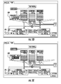
- FIG. 1A is an exemplary embodiment of a global visualization interface, generally designated 100, for providing aircraft operators with a comprehensive view of the state of the aircraft systems and their relations, in accordance with aspects of the subject matter described herein.
- the global visualization interface 100 has three levels connected by energy flow diagrams.
- the first level systems are Energy Consumer systems 102 such as Aircraft FIRE & SMOKE 104 systems, A-ICE & LIGHTS 106 systems, CABIN & CARGO 108 systems, AIRCRAFT CONTROL 110 systems and COCKPIT & AVIONICS 112 systems.
- the second level systems are Energy Distributor 103systems such as Air 116, ELEC 118, and HYD 120.
- the third level systems are Energy Supplier 122 systems such as auxiliary power unit (APU) 124, engine 1 (ENG 1) 130 and engine 2 (ENG 2) 126, and FUEL 128 systems.
- APU auxiliary power unit
- ENG 1 engine 1
- ENG 2 engine 2
- FUEL 128 FUEL 128
- an aircraft operator interacts with an aircraft system by using, for example, tactile features such as a touchscreen display, or interactive devices such as a computer mouse or track-wheel selector.
- tactile features such as a touchscreen display
- interactive devices such as a computer mouse or track-wheel selector.
- each of the graphic objects gives access to a local view of a management system about the associated aircraft system.
- the aircraft systems as displayed on the global visualization interface 100 are connected to other systems by various graphical icons representing energy flows.
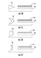
- Figure 1B depicts an exemplary illustration of a graphical icon 132 representing the flow of aircraft fuel.
- fuel flow icon 132 has long arrows 134 representing the direction of displacement of the fuel, which accentuates the effect of fluid movement when compared to the flows of ELEC (electrical) or HYD (hydraulic) systems for which there is little or no physical displacement.
- the FUEL 128 supplier system is configured to direct aircraft fuel to systems such as ENG1 126, ENG2 128, and APU 124.
- Figure 1C depicts an exemplary illustration of a graphical icon 136 representing the flow of electric flux.
- electric flux icon 136 includes marks with arrow shaped symbols 138.
- the aircraft engines (ENG 1 130 and ENG 2 126) and the APU 124 are configured to direct electric flux first to the ELEC 118 distributor system, and the ELEC 118 system then distributes the electric flux to energy consumer systems such as FIRE & SMOKE 104 systems, A-ICE & LIGHTS 106 systems, CABIN & CARGO 108 systems, AIRCRAFT CONTROL 110 systems and COCKPIT & AVIONICS 112 systems.
- energy consumer systems such as FIRE & SMOKE 104 systems, A-ICE & LIGHTS 106 systems, CABIN & CARGO 108 systems, AIRCRAFT CONTROL 110 systems and COCKPIT & AVIONICS 112 systems.
- Figure 1D depicts an exemplary illustration of a graphical icon 140 representing hydraulic flow of the aircraft.
- hydraulic flow 140 includes marks with arrows at base punt pointing out the hydraulic pistons.
- the aircraft engines ENG 1 130 and ENG 2 1266 are configured to direct hydraulic flux first to the HYD 120 distributor system, and the HYD 120 system then distributes the hydraulic flux to energy consumer systems such as the AIRCRAFT CONTROL 110 system.
- Figure 1E depicts an exemplary illustration of a graphical icon 144 representing airflow of the aircraft. As illustrated in Figure 1E , airflow 144 includes arcs symbolizing a wave of air volume displacement.
- the aircraft engines (ENG 1 130 and ENG 2 126) and the APU 124 are configured to direct air flow first to the AIR 116 distributor system, and the AIR 116 system then distributes the air flow to energy consumer systems such as the A-ICE & LIGHTS 106 system.
- energy consumer systems such as the A-ICE & LIGHTS 106 system.
- interruptions or breakdown of energy flows are represented with a solid line with no arrows depicting energy movements. For example, when fuel ceases to flow from FUEL 128 to aircraft engines ENG 1 130 and ENG2 126, the connection between these systems is represented by a solid line 148.
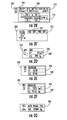
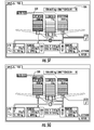
- FIG. 2A is an exemplary embodiment of a global visualization interface, generally designated 200, with inserts displayed for multiple graphic objects for providing additional systems information during different phases of a flight, in accordance with aspects of the subject matter described herein.
- Inserts are graphic icons placed on an interface configured to display systems information about an associated aircraft system.
- an AIR 204 insert is placed next to the graphic object AIR 116 and configured to display additional aircraft status information.
- the AIR 204 insert is configured to display aircraft status information such as effective cabin air pressure 206, effective cabin airspeed 208, effective cabin altimeter 210, and temperatures 212 at different segments of the cabin section.
- an A-ICE & LIGHTS insert is placed next to the graphic object A-ICE & LIGHTS showing that both nacelle anti-ice system 214 and wing anti-ice system 216 are switched off, as illustrated in Figure 2C .
- APU 224 insert, ENG 1 220 insert, and ENG 2 222 insert are provided to include information such as fuel flow rate 226 and fuel usage 228 of the APU 124, ENG 1 130, and ENG 2 126 systems, as illustrated in Figures 2D to 2F .
- a FUEL 230 insert is displayed next to the FUEL 128 system icon. As illustrated in Figure 2G , the FUEL 230 insert is configured to display information such as wing fuel tank operation mode and amount of fuel on board. It should be noted that other inserts can be conveniently inserted and displayed to provide other systems information as needed, the examples provided here are to explain the subject matter and not as a limitation.
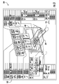
- the inserts are also useful to display, for each system, breakdown diagnoses when a system failure has occurred, as illustrated in Figure 3 .
- an A-ICE & LIGHTS 302 insert indicating at least one or more error status for an aircraft's A-ICE & FIRE system is placed on a global visualization interface 300 as depicted in Figure 3 .
- the errors are listed in an order determined by a flight database onboard the aircraft or according to standard operating procedure guidelines.
- the A-ICE & LIGHTS insert 302 is configured to display at least 3 errors, error 1 being the most critical whereas error 3 has the least impact (compared to the other 2 errors) on the aircraft.
- a breakdown in the energy flow between at least two systems is illustrated by a solid line 304, without arrows indicating any flow.
- corresponding inserts are displayed on the global visualization interface 300 as shown in Figure 3 .
- an aircraft operator has an overall picture of the failures of the aircraft, which enables the operator to coordinate his or her actions quickly, notably when the system cannot formulate any prescribed resolution plan.
- a system management interface configured for managing at least one or more aircraft system is accessible by interacting with an insert or a graphic object representing one or more functions realized by the considered system.
- the interface can be a local system management interface for local control on an aircraft.
- a user or operator interacts with the insert or the graphic object through any suitable technique, for example such as by tapping the insert on a tactile screen, or selecting the insert using an interactive device such as a computer mouse. Selecting an insert or the graphic object representing an aircraft system grants the operator access to a local system management interface of that system.
- one or more tab controls are available for navigating between a global view, a local system management view, and a task view of aircraft systems.
- a new mitre 400 or interface opens up and provides a way to manage that system locally.
- an additional interface icon 402 becomes available on the local system mitre 400 and provides a quick path back to the global visualization interface 100. As such, this configuration allows an aircraft operator to quickly access a particular system and just as quickly return to the global overview interface.
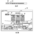
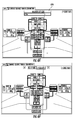
- FIG. 5A depicts an exemplary illustration of a system management interface, generally designated 500, for managing an aircraft's fuel supply in accordance with aspects of the subject matter described herein.
- the management interface 500 displays the current status of the aircraft's hydrocarbon containing system, such as quantities of fuel, flow of the fuel, and operations of the fuel pumps.
- system components of the fuel supply system e.g. pumps, valves, fuel tanks, etc.
- graphic objects e.g. pumps, valves, fuel tanks, etc.
- the system components are placed on the interface in one aspect in reference or relation to their physical locations on the aircraft.
- the real fitting of the fuel tanks on the aircraft is reproduced on the management interface 500 by indicating on the left a representation of the fuel tank present in the left wing 502 and on the right a symbol representing the fuel tank of the right wing 504.
- a center CENTER 506 fuel tank is placed between the LEFT WING 502 and RIGHT WING 504 fuel tanks representing the fuel stored in the aircraft's central fuselage.
- Each fuel tank has at least one or more pump 508 for controlling the fuel flow and is connected to aircraft systems represented by inserts such as the APU 224, ENG 1 220 and ENG 2 222 inserts.
- valve 510 for controlling the fuel flow to various aircraft systems and powered by the ELEC 118 distributor system.
- ELEC 118 provides quick access to a management interface to the aircraft's electrical system.
- the amount of fuel available is displayed both numerically and graphically.
- fuel-on-board 512 is displayed numerically on top of the management interface 500, and so is the amount of fuel available in each tank.
- each tank also depicts the amount of fuel available graphically, for example, as stacked blocks similar to a cell phone displaying the amount of battery power left.
- the circulation of the fuel is also displayed. For example, a line of arrows coming out of the fuel tanks and into aircraft systems represent the movement of aircraft fuel. This configuration provides an overview of the aircraft's fuel system and allows an operator to act quickly.
- system function sequences are activated following one or more prescribed sequences.
- the fuel carburizing system is configured to operate in an AUTO FEED 514 mode by default, which gives an operator full authority to configure the fuel supply according to procedures determined by priorities set by a flight database onboard the aircraft or in standard operating procedure guidelines. The determination of priorities takes into consideration factors such as different flight phases, the operating aircraft systems, and/or any breakdowns or aircraft system failures.
- the AUTO FEED mode the CENTER 506 fuel tank would be exhausted first, followed by the LEFT WING 502 and RIGHT WING 504 tanks, thereby reducing stresses undergone by aircraft wing structures during cruising.
- an aircraft operator is fully authorized to activate or deactivate a system component through user interaction with a graphic object on the management interface. For example, by tapping on the graphic object representing a fuel tank, an operator is manually selecting and/or deselecting the tank independently of other system components, and the FUEL 500 management system will reconfigure the pumps 508 and valves 510 automatically in order to adequately supply fuel to all aircraft systems, starting from the activated fuel tank.
- This configuration is referred to as the "functional interaction", as it is abstracted from the equipment which is programmed to execute the settings as configured in a strict manner, such as open and close valves 510, or start and/or stop the fuel pumps 508.
- Functional interaction is an improvement over current systems, where an aircraft operator is required to toggle multiple switches in a prescribed order to configure valves and pumps to reroute the fuel supply.
- Centralizing the controls in the FUEL management interface 500 not only lightens the workload of the operator, but also reduces overall risk due to human errors.
- an operator deselects the CENTER 506 tank and selects the LEFT WING 502 and RIGHT WING 504 tanks, at which point the AUTO FEED 514 mode is automatically disabled.
- interacting with graphic objects on the management interface allows an aircraft operator to activate a manual feed mode for supplying fuel to aircraft fuel tanks and/or for removing fuel from aircraft fuel tanks. For example, by tapping graphic objects representing fuel valves on the local system management interface, the aircraft operator can adjust aircraft fuel levels in the aircraft's left wing tank, right wing tank, center tank, or a combination thereof.
- the safeguard mechanism will require the operator to take a specific interaction, such as drag the command icon 518 into the center of the zone at risk 516 to confirm the execution of the operator's command.
- This mechanism will work with other fuel tanks in a similar fashion, and can eliminate unintentional commands and notify aircraft operators to consequential operational risks.
- the FUEL 500 management interface is also configured to manage abnormal system configurations and failures. For example, under AUTO FEED mode, the difference in the amount of fuel in the left and right wing tanks is automatically maintained at or below a threshold level (e.g. 300kg), such as for example by activating a rebalancing mechanism at convenient times throughout a flight. However, when an operator disables the AUTO FEED mode and puts the fuel system in a different configuration, an imbalance of amount of fuel between the tanks can develop. When the imbalance exceeds a threshold level (e.g. 300kg), a contextual icon will appear to indicate the imbalance and ask for rebalancing of aircraft fuel between the two tanks.
- a threshold level e.g. 300kg
- rebalancing icon 520 is displayed next to the fuel tanks indicating a fuel imbalance exceeding the threshold level.
- a proposed procedure box 524 appears within the rebalancing icon 520 depicting the proposed command needed to rebalance the fuels. The operator can select and confirm the command, at which point fuel flow between the tanks is automatically initiated to correct the imbalance, as illustrated in Figure 5E .
- systems in use today require an aircraft operator to rebalance the fuel through a procedure consisting of opening and closing a series of valves and pumps, and then to reactivate the valves and pumps once a balance has been achieved. The part of reactivating valves and pumps is regularly forgotten by operators and thus reverses the fuel imbalance.
- the present subject matter drastically simplifies the rebalancing process for the operator, as well as making it more reliable and safer. It should be noted that other system functions or anomalies can also be conveniently brought to an operator's attention and then corrected by the method described herein.
- the example of fuel imbalance is provided here to explain the subject matter and not as a limitation.
- FUEL 500 management interface indicates to the operator that such fuel will not be usable directly (e.g. change the displaying color of the fuel in the faulty tank), but will become available when the aircraft passes under a particular flight ceiling.
- a GRAVITY FEED CEILING FL 130 526 as indicated on the management interface 500, a GRAVITY FEED AVAIL indicator 528 appears on top of the LEFT WING 502 icon to indicate the activation of gravity enabled fuel feeding, as illustrated in FIGURE 5G .
- an aircraft operator has the option to directly control the pumps 508 and valves 510 of the fuel system for managing an unprescribed emergency situation such as a fuel leak not detected by onboard sensors.
- the safeguard mechanism is still present as a safety net, preventing the operator from executing potentially disastrous commands.
- a "zone at risk" 528 is displayed over the valve 510, wide enough to draw attention from the operator.
- the command to close the valve 510 is blocked and potential risk of the action is displayed on a command icon 530.
- the safeguard mechanism will require the operator to take a specific interaction, such as for example to drag the command icon 530 into the center of zone at risk 528 to confirm the execution of the operator's command.
- command icons such as JETTISON 532 and REFUEL 534 are also placed on the FUEL management interface 500, allowing quick configuration and execution of refueling the plane on the ground or jettison fuel in the air. It should be noted that other quick access command icons can be conveniently placed on a system management interface for fast execution of prescribed configuration commands.
- system function sequences such as JETTISON 532 and REFUEL 534 require a configuration phase before execution. For example, aircraft fuel balancing parameters need to be collected and analyzed before adding or jettisoning fuel to or from the aircraft.
- a prescribed situation can occur when onboard sensors detect a smoke source and responses are prescribed for an aircraft operator to resolve the fault.
- task-specific action sequences such as smoke source troubleshooting procedures are performed through several onboard interfaces, including a task-specific action sequence presented in a printed Quick Reference Handbook, a series of "ON/OFF" commands for potential sources disposed in an overhead panel, systems reconfiguration controls disposed across the cockpit for reallocating communication frequencies on non-shutdown radio controls, and a display of potential sources on a plurality of system pages and overhead panel lights.
- performing an action sequence comprises reconfiguring a shutdown system to another resource and providing a backup capability. For example, during a smoke source troubleshooting sequence, the sequence shuts down one electrical generator while keeping the other generators operational.
- the interactive system described in the present subject matter prescribes a task to be performed by the operator and then illustrate a task view at an appropriate time.
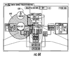
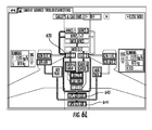
- the operator has the option to activate a particular task view from a pre-defined list when the operator detects an event not picked by the aircraft's sensors. For example, as illustrated in Figure 6A , when smoke is detected by the operator, a task-specific interface such as SMOKE SOURCE TROUBLESHOOTING 600 interface is activated for finding the source of the smoke.
- the SMOKE SOURCE TROUBLESHOOTING 600 interface is configured to diagnose and repair a malfunctioning aircraft system and includes interactive icons such as a tab control 602 for a quick navigation back to a global system view and a manual control icon 604 for disabling the TROUBLESHOOTING 600 interface.
- the TROUBLESHOOTING 600 interface allows the operator to follow a prescribed system function sequence by activating a series of macro actions.
- the system function sequence can include one or more predefined system functions, for example, as illustrated in Figure 6A , a macro action icon 606 is displayed on the interface allowing the operator to perform a particular system function, and a manual control icon 608 is also available for navigating to the next system function in the sequence.
- Also displayed on the TROUBLESHOOTING 600 interface are systems icons that represent possible sources of smoke, which an operator can turn off manually.
- the operator is first requested to shut down the Galleys and Cabin fans, the two most probable causes of smoke emission and dissemination.
- the operator selects the OFF control on the macro action icon 606, then GALLEYs and CAB FANS are turned OFF, and the next step on the smoke troubleshooting sequence is activated.
- the APU is selected to be not running, therefore APU generated electricity and air (APU GEN ELEC 610 and APU GEN AIR 612) are not running as well.
- the smoke troubleshooting sequence then proceeds automatically to the next step, which is isolating the left side of the aircraft as shown in Figure 6C .
- systems such as the GEN ELEC 1 614, GEN AIR 1 616, AIR PACK 1 618, ELEC 1 620, AND CABIN & CARGO 1 622 will get reconfigured on the right side redundancies and then closed down. Also closed off are associated energy flows between the systems, which are represented as solid lines without arrows indicating no energy movements.
- the operator will be prompted, as shown in prompt box 624, to answer if the smoke has dissipated, without a time limitation, as illustrated in Figure 6D . If the operator selects "NO" in the prompt box 624, then the left side systems (e.g. GEN ELEC 1 614, GEN AIR 1 616, AIR PACK 1 618, ELEC 1 620, AND CABIN & CARGO 1 622 ) can be recovered, as shown in Figure 6E , and a recovery status box 626 appears to indicate the progress of systems recovery. Alternatively, as Figure 6F illustrates, the aforementioned process is repeated, this time for the right side of the aircraft, isolating the potential smoke sources there.
- the left side systems e.g. GEN ELEC 1 614, GEN AIR 1 616, AIR PACK 1 618, ELEC 1 620, AND CABIN & CARGO 1 622
- Figure 6E illustrates, the aforementioned process is repeated, this time for
- the operator is then prompted to confirm if the macro-action of isolating the right side was effective, as illustrated in Figure 6G .
- the troubleshooting sequence is configured to proceed to the next macro-action of switching on an emergency electrical supply that only keeps emergency electrical systems powered.
- the deployment of emergency electrical systems is shown, for example, in Figure 6H , with a status box 628 displayed on the screen indicating the progress of the deployment.
- the activation of the emergency electrical supply EMER ELEC 630 also activates a ram air turbine RAT 632, and the RAT 632 deploys itself prior to the disconnection of the left side systems.
- the RAT 632 is configured to provide emergency electricity to the EMER ELEC 630 core, which supplies electricity to the emergency avionics EMER AVNCS 632. At this point the operator is then requested to close the task as no further action can be performed to eliminate the smoke source.
- This exemplary response method for troubleshooting a smoke source in a reduced number of steps advantageously enables the operating crew members to methodically check the source of the smoke while maintaining a safe and operable aircraft as long as possible.
- the representation of potential smoke source systems gathered on the same view below macro action enable the crew to have an overview of the effect of macro-action on individual systems.
- the operator instead of going through a task-specific action sequence such as the smoke troubleshooting sequence, the operator is aware of the possible sources of the smoke and is fully authorized to interact directly with the displayed aircraft systems, and the safeguard mechanism is in place to protect against abnormal and/or dangerous systems commands. For example, as shown in Figure 6J , the operator decides to directly shut down the GEN ELEC 2 634 and GEN AIR 2 636 systems because engine 2 is showing high vibrations while there is smoke in the cabin. Then when the operator tries to set GEN ELEC 1 614 off, the safeguard mechanism gets activated and places a "zone at risk" 640 over the GEN ELEC 1 614 system icon, wide enough to draw attention from the operator, as illustrated in Figure 6K .
- the order to deselect the GEN ELEC 1 614 is blocked and potential risk of the action is displayed on a command icon 638.
- the safeguard mechanism will require the operator to take a specific interaction, such as drag the command icon 638 into the center of zone at risk 640 to confirm the execution of the operator's command.
- which operator command would set the aircraft in danger is determined dynamically by the safeguard mechanism.
- the APU APU GEN ELEC 642 and APU GEN AIR 644.
- the safeguard mechanism will not be activated to block this command, because ELEC 1 620 core is now powered by the APU GEN ELEC 642.
- some of the aircraft's systems cannot be directly controlled by an aircraft operator through the TROUBLESHOOTING 600 interface.
- systems such as AVNCS 1 646 and AVNCS 2 648 cannot be turned off by the operator on this aircraft architecture.
- a popup 650 will inform the operator such command cannot be executed.
- an operator can still turn off the AVNCS 1 646 system indirectly, by cutting off its power supply from ELEC 1 620.
- an interface system includes graphic objects representing principal elements (e.g. tanks, valves, generators, pumps, etc.) of an aircraft according to their physical locations on the aircraft (e.g. right wing, left wing, cabin, etc.).
- the systems are connected by various energy flows (e.g. fuel electricity, air, water, etc.) according to the energy flow's direction of circulation as configured in the aircraft.
- aircraft fuel can be directed from the wing tanks to the engines, and air can be directed by generators to the cabin.
- Important consumer systems such as fire & smoke systems, or cockpit & avionics systems, are to be displayed either by default and/or by aircraft operator preference, and descriptive information about a system is also displayed.
- system failures and emergency functions e.g. fuel imbalance, smoke source troubleshooting, etc. are also displayed and accessible from the interface.
- the graphic objects also inform the aircraft operator as to the state of the associated aircraft system. For example, a system can be shown to be operational or degraded, locked or active, and/or deployment in progress.
- the graphic object also gives the operator access and control to that system.
- multiple interfaces are to be integrated into a centralized platform configured to include several tactile devices.
- an ABNORMAL MISSION MANAGEMENT interface will pop up automatically or at a pilot's request, to a screen next to the global management interface, or even share the same screen as the management interface.
- Figure 6N is an exemplary illustration of a collection of graphic objects usable by a management interface, in accordance with aspects of the subject matter described herein.
- the graphic objects can have different contour, color and/or geometric characteristics and are controllable by the management interface. For example, having color in the center of a graphic object makes it possible to show to system being active or inactive (e.g. blue being active, grey being inactive, etc.) Blue is preferably retained because it is a cold color that is known to favor serenity, on the contrary to amber and green that are hotter and are associated with danger.
- the first contour makes it possible to indicate if a button is actionable or not., and the color of contour makes it possible to indicate the system is operational or degraded.
- the collection of graphic objects displayed in Figure 6N can be conveniently changed depending on the airline preference or cockpit configurations, as they are provided and described herein to explain the subject matter and not as a limitation.
Abstract
Description
- The subject matter described herein relates generally to aircraft systems management. More particularly, the subject matter disclosed herein relates to methods, systems and computer readable media for a centralized integrated view for the management of aircraft systems, during both normal and abnormal situations of an aircraft's operation.
- The management of a plurality of aircraft systems in current configurations, including fuel, electric, engines, and orders of flight is performed using three devices. First, a screen displays some information about these systems, gathering various parameters measured by sensors, as well as the state of the equipment composing each system of the plane. Secondly, an order-system overhead panel equipped with a plurality of buttons, chokes, and switches that act on the various systems allows an aircraft operator to control these various systems, with an increased level of confusion associated with the significant number of such control buttons, chokes, and switches available on the panel. Thirdly, a screen displays any breakdowns detected by the systems as well as the procedure to limit the impact of these breakdowns on the safety of the flight and the other flight operations.
- There is a need to simplify these systems and reduce the possibility for errors made by the operator when responding to situations that arise during flight operations.
- According to one aspect, the subject matter described herein comprises a method for managing an aircraft's systems through a dedicated interface. The method includes, at least one global visualization interface for managing aircraft systems and comprising a hardware processor, displaying at least one or more graphic object representing at least one or more aircraft system, displaying at least one or more energy flow icon representing the direction of circulation of an energy flow, and accessing a system management interface, that can be a local system management interface for local control on an aircraft, of the at least one or more aircraft system through performing a user interaction with the graphic object.
- According to another aspect, the subject matter described herein comprises a system for managing an aircraft's systems. The system includes a dedicated global visualization interface for managing aircraft systems and comprising a hardware processor. The interface comprises at least one or more graphic object representing at least one or more functions realized by the considered system, and at least one or more energy flow icon representing the direction of circulation of an energy flow.
- According to yet another aspect, the subject matter described herein comprises a non-transitory computer readable medium having stored thereon executable instructions that when executed by the processor of a computer control the computer performs, at a global visualization interface for managing aircraft systems and comprising a hardware processor, displaying at least one or more graphic object representing at least one or more aircraft system, displaying at least one or more energy flow icon representing the direction of circulation of an energy flow, and accessing a system management interface of the at least one or more aircraft system through performing a user interaction with the graphic object.
- The subject matter described herein can be implemented in software in combination with hardware and/or firmware. For example, the subject matter described herein may be implemented in software executed by one or more processors. In one exemplary implementation, the subject matter described herein may be implemented using a non-transitory computer readable medium having stored thereon computer executable instructions that when executed by the processor of a computer control the computer to perform steps. Exemplary computer readable media suitable for implementing the subject matter described herein can include non-transitory computer readable media such as, for example and without limitation, disk memory devices, chip memory devices, programmable logic devices, and application specific integrated circuits. In addition, a computer readable medium that implements the subject matter described herein may be located on a single device or computing platform or may be distributed across multiple devices or computing platforms.
- The subject matter described herein will now be explained with reference to the accompanying drawings, of which:
-
Figure 1A is an exemplary embodiment of a global visualization interface for providing aircraft operators with a comprehensive view of the state of the aircraft systems and their relations in accordance with aspects of the subject matter described herein; -
Figures 1B to 1E are exemplary embodiments of energy flow icons in accordance with aspects of the subject matter described herein; -
Figure 2A is an exemplary embodiment of a global visualization interface with multiple inserts displaying aircraft systems information in accordance with aspects of the subject matter described herein; -
Figures 2B to 2G are exemplary embodiments of inserts displaying aircraft information in accordance with aspects of the subject matter described herein; -
Figure 3 is an exemplary embodiment of a global visualization interface with multiple inserts displaying system error messages in accordance with aspects of the subject matter described herein; -
Figure 4 illustrates tab controls for navigating between a global view, a local system management view, and a task view in accordance with aspects of the subject matter described herein; -
Figure 5A is an exemplary embodiment of a management interface for an aircraft system in accordance with aspects of the subject matter described herein; -
Figures 5B to 5H are exemplary embodiments of an aircraft operator performing system management through the management interface in accordance with aspects of the subject matter described herein; -
Figure 6A is an exemplary embodiment of a task-specific interface in accordance with aspects of the subject matter described herein; -
Figures 6B to 6H are exemplary embodiments of an automated task-specific action sequence in accordance with aspects of the subject matter described herein; -
Figures 6I to 6M are exemplary embodiments of performing manual troubleshooting on an aircraft system failure in accordance with aspects of the subject matter described herein; and -
Figure 6N is an exemplary illustration of a collection of graphic objects usable by a management interface in accordance with aspects of the subject matter described herein. - In accordance with the description herein and exemplary, associated drawings, novel methods, systems, and computer readable media are disclosed for simulating user interactions with a simulated aircraft cockpit. Such methods, systems and computer readable media are particularly suitable for use, for example and without limitation, for 3D modeling of a cockpit associated with an emulation of aircraft systems.
- Notably, the subject matter described herein provides an integrated interface system for the simplification of the management of systems of an aircraft for use during either a prescribed situation or a non-prescribed situation that may occur during flight operations. A prescribed flight situation includes flight operations situations when the aircraft operating systems indicate or emit a diagnosis of breakdown, or when an operator detects a breakdown not detected by the aircraft operating systems. In this case, a known procedure is applied in response to the detected breakdown. Prescribed flight situations occur when the aircraft operating systems require an operator to configure a setting in a particular configuration in response to the detected breakdown, or for the operator to pay attention to a particular aircraft operating system or operating parameter. A prescribed flight situation could include, for example, the detection of an unknown source of smoke, detected by either the operator or operating systems onboard the aircraft.
- A non-prescribed flight situation occurs when the aircraft operating systems indicate that the aircraft operating systems do not detect any abnormal situation or condition, whereas the aircraft is in a situation recognized by the operator as dangerous or abnormal for the given flight conditions. In this non-prescribed flight situation, a coherent action plan cannot be formulated by the aircraft operating systems, or no procedure exists for the current flight situation for the operator to follow in order to resolve the abnormality in the flight conditions. Non-prescribed flight situations occur, for example, when the operator wishes to put the plane in a particular configuration or to visualize particular parameters not required by a procedure outlined by standard flight operating procedures. A non-prescribed flight situation could include the investigation of managing remaining fuel onboard the aircraft by the operator.
- In some aspects, an aircraft's various systems are managed through an unique device with dedicated interfaces.
Figures 1A is an exemplary embodiment of a global visualization interface, generally designated 100, for providing aircraft operators with a comprehensive view of the state of the aircraft systems and their relations, in accordance with aspects of the subject matter described herein. In some aspects, theglobal visualization interface 100 has three levels connected by energy flow diagrams. The first level systems areEnergy Consumer systems 102 such as Aircraft FIRE & SMOKE 104 systems, A-ICE & LIGHTS 106 systems, CABIN & CARGO 108 systems, AIRCRAFT CONTROL 110 systems and COCKPIT & AVIONICS 112 systems. The second level systems are Energy Distributor 103systems such as Air 116, ELEC 118, and HYD 120. The third level systems are Energy Supplier 122 systems such as auxiliary power unit (APU) 124, engine 1 (ENG 1) 130 and engine 2 (ENG 2) 126, and FUEL 128 systems. Each system is represented with a graphical object such as a volume in axonometric perspective, associated with a textual label and graphic symbol describing the associated aircraft system. - In some aspects, an aircraft operator interacts with an aircraft system by using, for example, tactile features such as a touchscreen display, or interactive devices such as a computer mouse or track-wheel selector. When selected, each of the graphic objects gives access to a local view of a management system about the associated aircraft system.
- In some aspects, the aircraft systems as displayed on the
global visualization interface 100 are connected to other systems by various graphical icons representing energy flows. For example,Figure 1B depicts an exemplary illustration of agraphical icon 132 representing the flow of aircraft fuel. As illustrated inFigure 1B ,fuel flow icon 132 haslong arrows 134 representing the direction of displacement of the fuel, which accentuates the effect of fluid movement when compared to the flows of ELEC (electrical) or HYD (hydraulic) systems for which there is little or no physical displacement. Referring back toFigure 1A , the FUEL 128 supplier system is configured to direct aircraft fuel to systems such as ENG1 126, ENG2 128, and APU 124. Similarly,Figure 1C depicts an exemplary illustration of agraphical icon 136 representing the flow of electric flux. As illustrated inFigure 1C ,electric flux icon 136 includes marks with arrow shapedsymbols 138. Referring back toFigure 1A , the aircraft engines (ENG 1 130 and ENG 2 126) and the APU 124 are configured to direct electric flux first to the ELEC 118 distributor system, and the ELEC 118 system then distributes the electric flux to energy consumer systems such as FIRE & SMOKE 104 systems, A-ICE & LIGHTS 106 systems, CABIN & CARGO 108 systems, AIRCRAFT CONTROL 110 systems and COCKPIT & AVIONICS 112 systems. Furthermore,Figure 1D depicts an exemplary illustration of agraphical icon 140 representing hydraulic flow of the aircraft. As illustrated inFigure 1D ,hydraulic flow 140 includes marks with arrows at base punt pointing out the hydraulic pistons. Referring back toFigure 1A , the aircraft engines (ENG 1 130 andENG 2 126) are configured to direct hydraulic flux first to theHYD 120 distributor system, and theHYD 120 system then distributes the hydraulic flux to energy consumer systems such as theAIRCRAFT CONTROL 110 system. In addition,Figure 1E depicts an exemplary illustration of agraphical icon 144 representing airflow of the aircraft. As illustrated inFigure 1E ,airflow 144 includes arcs symbolizing a wave of air volume displacement. Referring back toFigure 1A , the aircraft engines (ENG 1 130 andENG 2 126) and theAPU 124 are configured to direct air flow first to theAIR 116 distributor system, and theAIR 116 system then distributes the air flow to energy consumer systems such as the A-ICE &LIGHTS 106 system. It should be noted that other symbols or icons can be easily utilized to represent various types of flows, as the examples provided herein are intended to explain the subject matter and not as a limitation. Furthermore, interruptions or breakdown of energy flows are represented with a solid line with no arrows depicting energy movements. For example, when fuel ceases to flow fromFUEL 128 toaircraft engines ENG 1 130 andENG2 126, the connection between these systems is represented by asolid line 148. - In some aspects, contextual and/or supplemental information are displayed along sides of the graphic objects representing aircraft systems to provide additional systems data to aircraft operators.
Figures 2A is an exemplary embodiment of a global visualization interface, generally designated 200, with inserts displayed for multiple graphic objects for providing additional systems information during different phases of a flight, in accordance with aspects of the subject matter described herein. Inserts are graphic icons placed on an interface configured to display systems information about an associated aircraft system. For example, anAIR 204 insert is placed next to thegraphic object AIR 116 and configured to display additional aircraft status information. As illustrated inFigure 2B , theAIR 204 insert is configured to display aircraft status information such as effectivecabin air pressure 206,effective cabin airspeed 208,effective cabin altimeter 210, andtemperatures 212 at different segments of the cabin section. Similarly, an A-ICE & LIGHTS insert is placed next to the graphic object A-ICE & LIGHTS showing that bothnacelle anti-ice system 214 andwing anti-ice system 216 are switched off, as illustrated inFigure 2C . Furthermore,APU 224 insert,ENG 1 220 insert, andENG 2 222 insert are provided to include information such asfuel flow rate 226 andfuel usage 228 of theAPU 124,ENG 1 130, andENG 2 126 systems, as illustrated inFigures 2D to 2F . In addition, aFUEL 230 insert is displayed next to theFUEL 128 system icon. As illustrated inFigure 2G , theFUEL 230 insert is configured to display information such as wing fuel tank operation mode and amount of fuel on board. It should be noted that other inserts can be conveniently inserted and displayed to provide other systems information as needed, the examples provided here are to explain the subject matter and not as a limitation. - In some aspects, the inserts are also useful to display, for each system, breakdown diagnoses when a system failure has occurred, as illustrated in
Figure 3 . For example, an A-ICE &LIGHTS 302 insert indicating at least one or more error status for an aircraft's A-ICE & FIRE system is placed on aglobal visualization interface 300 as depicted inFigure 3 . Furthermore, in situations where multiple errors have occurred within a single system, the errors are listed in an order determined by a flight database onboard the aircraft or according to standard operating procedure guidelines. For example, as shown inFigure 3 , the A-ICE & LIGHTS insert 302 is configured to display at least 3 errors,error 1 being the most critical whereaserror 3 has the least impact (compared to the other 2 errors) on the aircraft. Similarly a breakdown in the energy flow between at least two systems is illustrated by asolid line 304, without arrows indicating any flow. When multiple systems are experiencing failures, corresponding inserts are displayed on theglobal visualization interface 300 as shown inFigure 3 . As such, an aircraft operator has an overall picture of the failures of the aircraft, which enables the operator to coordinate his or her actions quickly, notably when the system cannot formulate any prescribed resolution plan. - In some aspects, a system management interface configured for managing at least one or more aircraft system is accessible by interacting with an insert or a graphic object representing one or more functions realized by the considered system. The interface can be a local system management interface for local control on an aircraft. A user or operator interacts with the insert or the graphic object through any suitable technique, for example such as by tapping the insert on a tactile screen, or selecting the insert using an interactive device such as a computer mouse. Selecting an insert or the graphic object representing an aircraft system grants the operator access to a local system management interface of that system. For example, as illustrated in
Figure 4 , one or more tab controls are available for navigating between a global view, a local system management view, and a task view of aircraft systems. For example, when an aircraft operator selects a system icon or a tab_or the insert associated with theFUEL 128 system, anew mitre 400 or interface opens up and provides a way to manage that system locally. Furthermore, anadditional interface icon 402 becomes available on thelocal system mitre 400 and provides a quick path back to theglobal visualization interface 100. As such, this configuration allows an aircraft operator to quickly access a particular system and just as quickly return to the global overview interface. - In some aspects, an operator is capable of accessing and/or managing an aircraft system through a dedicated management interface. For example,
Figure 5A depicts an exemplary illustration of a system management interface, generally designated 500, for managing an aircraft's fuel supply in accordance with aspects of the subject matter described herein. As shown inFigure 5A , themanagement interface 500 displays the current status of the aircraft's hydrocarbon containing system, such as quantities of fuel, flow of the fuel, and operations of the fuel pumps. Also shown on themanagement interface 500 are system components of the fuel supply system (e.g. pumps, valves, fuel tanks, etc.) represented by graphic objects and a virtualized layout of the system including the fuel tanks, valves and pumps. As illustrated inFigure 5A , the system components are placed on the interface in one aspect in reference or relation to their physical locations on the aircraft. For example, the real fitting of the fuel tanks on the aircraft is reproduced on themanagement interface 500 by indicating on the left a representation of the fuel tank present in theleft wing 502 and on the right a symbol representing the fuel tank of theright wing 504. Similarly, acenter CENTER 506 fuel tank is placed between theLEFT WING 502 andRIGHT WING 504 fuel tanks representing the fuel stored in the aircraft's central fuselage. Each fuel tank has at least one ormore pump 508 for controlling the fuel flow and is connected to aircraft systems represented by inserts such as theAPU 224,ENG 1 220 andENG 2 222 inserts. There is also avalve 510 for controlling the fuel flow to various aircraft systems and powered by theELEC 118 distributor system. In the event of failure of the aircraft electrical system,ELEC 118 provides quick access to a management interface to the aircraft's electrical system. In some aspects, the amount of fuel available is displayed both numerically and graphically. For example, fuel-on-board 512 is displayed numerically on top of themanagement interface 500, and so is the amount of fuel available in each tank. However, each tank also depicts the amount of fuel available graphically, for example, as stacked blocks similar to a cell phone displaying the amount of battery power left. In addition, the circulation of the fuel is also displayed. For example, a line of arrows coming out of the fuel tanks and into aircraft systems represent the movement of aircraft fuel. This configuration provides an overview of the aircraft's fuel system and allows an operator to act quickly. - In some aspects, system function sequences are activated following one or more prescribed sequences. For example, the fuel carburizing system is configured to operate in an
AUTO FEED 514 mode by default, which gives an operator full authority to configure the fuel supply according to procedures determined by priorities set by a flight database onboard the aircraft or in standard operating procedure guidelines. The determination of priorities takes into consideration factors such as different flight phases, the operating aircraft systems, and/or any breakdowns or aircraft system failures. Under the AUTO FEED mode, theCENTER 506 fuel tank would be exhausted first, followed by theLEFT WING 502 andRIGHT WING 504 tanks, thereby reducing stresses undergone by aircraft wing structures during cruising. - In some aspects, an aircraft operator is fully authorized to activate or deactivate a system component through user interaction with a graphic object on the management interface. For example, by tapping on the graphic object representing a fuel tank, an operator is manually selecting and/or deselecting the tank independently of other system components, and the
FUEL 500 management system will reconfigure thepumps 508 andvalves 510 automatically in order to adequately supply fuel to all aircraft systems, starting from the activated fuel tank. This configuration is referred to as the "functional interaction", as it is abstracted from the equipment which is programmed to execute the settings as configured in a strict manner, such as open andclose valves 510, or start and/or stop the fuel pumps 508. Functional interaction is an improvement over current systems, where an aircraft operator is required to toggle multiple switches in a prescribed order to configure valves and pumps to reroute the fuel supply. Centralizing the controls in theFUEL management interface 500 not only lightens the workload of the operator, but also reduces overall risk due to human errors. In some aspects, as illustrated inFigure 5B , an operator deselects theCENTER 506 tank and selects theLEFT WING 502 andRIGHT WING 504 tanks, at which point theAUTO FEED 514 mode is automatically disabled. In some aspects, interacting with graphic objects on the management interface allows an aircraft operator to activate a manual feed mode for supplying fuel to aircraft fuel tanks and/or for removing fuel from aircraft fuel tanks. For example, by tapping graphic objects representing fuel valves on the local system management interface, the aircraft operator can adjust aircraft fuel levels in the aircraft's left wing tank, right wing tank, center tank, or a combination thereof. - In some aspects, inappropriate configuration commands or operating procedures that would put an aircraft in potential danger is prevented by a safeguard mechanism. For example, as illustrated in
Figure 5C , when only theRIGHT WING 504 tank is supplying fuel to both engines (ENG 1 220ENG 2 222), deselecting and therefore closing off theRIGHT WING 504 tank would effectively cut off the fuel supply to the aircraft completely. To prevent this type of situation from occurring, a confirmation to take action is requested by the system and displayed on theinterface 500. For example, "zone at risk" 516 is displayed over theRIGHT WING 504 tank, conspicuous and wide enough to draw attention from the operator. At the same time, the order to deselect theRIGHT WING 504 tank is blocked and potential risk of the action is displayed on acommand icon 518. The safeguard mechanism will require the operator to take a specific interaction, such as drag thecommand icon 518 into the center of the zone atrisk 516 to confirm the execution of the operator's command. This mechanism will work with other fuel tanks in a similar fashion, and can eliminate unintentional commands and notify aircraft operators to consequential operational risks. - In some aspects, the
FUEL 500 management interface is also configured to manage abnormal system configurations and failures. For example, under AUTO FEED mode, the difference in the amount of fuel in the left and right wing tanks is automatically maintained at or below a threshold level (e.g. 300kg), such as for example by activating a rebalancing mechanism at convenient times throughout a flight. However, when an operator disables the AUTO FEED mode and puts the fuel system in a different configuration, an imbalance of amount of fuel between the tanks can develop. When the imbalance exceeds a threshold level (e.g. 300kg), a contextual icon will appear to indicate the imbalance and ask for rebalancing of aircraft fuel between the two tanks. For example, as illustrated inFigure 5D ,rebalancing icon 520 is displayed next to the fuel tanks indicating a fuel imbalance exceeding the threshold level. A proposedprocedure box 524 appears within therebalancing icon 520 depicting the proposed command needed to rebalance the fuels. The operator can select and confirm the command, at which point fuel flow between the tanks is automatically initiated to correct the imbalance, as illustrated inFigure 5E . In comparison, systems in use today require an aircraft operator to rebalance the fuel through a procedure consisting of opening and closing a series of valves and pumps, and then to reactivate the valves and pumps once a balance has been achieved. The part of reactivating valves and pumps is regularly forgotten by operators and thus reverses the fuel imbalance. The present subject matter drastically simplifies the rebalancing process for the operator, as well as making it more reliable and safer. It should be noted that other system functions or anomalies can also be conveniently brought to an operator's attention and then corrected by the method described herein. The example of fuel imbalance is provided here to explain the subject matter and not as a limitation. - In some aspects, under certain operational conditions, when a fuel tank fails to function, it is possible to still draw fuel from that tank using gravity. For example, as illustrated in
Figure 5F , when a fuel tank ceases to operate (e.g. theLEFT WING 502 fuel tank), theFUEL 500 management interface indicates to the operator that such fuel will not be usable directly (e.g. change the displaying color of the fuel in the faulty tank), but will become available when the aircraft passes under a particular flight ceiling. For example, for Airbus A320 aircraft, once the plane passes under a GRAVITYFEED CEILING FL 130 526 as indicated on themanagement interface 500, a GRAVITYFEED AVAIL indicator 528 appears on top of theLEFT WING 502 icon to indicate the activation of gravity enabled fuel feeding, as illustrated inFIGURE 5G . - In some aspects, an aircraft operator has the option to directly control the
pumps 508 andvalves 510 of the fuel system for managing an unprescribed emergency situation such as a fuel leak not detected by onboard sensors. However, the safeguard mechanism is still present as a safety net, preventing the operator from executing potentially disastrous commands. For example, as illustrated inFigure 5H , to close off thevalve 510, a "zone at risk" 528 is displayed over thevalve 510, wide enough to draw attention from the operator. At the same time, the command to close thevalve 510 is blocked and potential risk of the action is displayed on acommand icon 530. The safeguard mechanism will require the operator to take a specific interaction, such as for example to drag thecommand icon 530 into the center of zone atrisk 528 to confirm the execution of the operator's command. - In addition, in some aspects, command icons such as
JETTISON 532 and REFUEL 534 are also placed on theFUEL management interface 500, allowing quick configuration and execution of refueling the plane on the ground or jettison fuel in the air. It should be noted that other quick access command icons can be conveniently placed on a system management interface for fast execution of prescribed configuration commands. In addition, in some aspects, system function sequences such asJETTISON 532 and REFUEL 534 require a configuration phase before execution. For example, aircraft fuel balancing parameters need to be collected and analyzed before adding or jettisoning fuel to or from the aircraft. - In some aspects a prescribed situation can occur when onboard sensors detect a smoke source and responses are prescribed for an aircraft operator to resolve the fault. In current practice, task-specific action sequences such as smoke source troubleshooting procedures are performed through several onboard interfaces, including a task-specific action sequence presented in a printed Quick Reference Handbook, a series of "ON/OFF" commands for potential sources disposed in an overhead panel, systems reconfiguration controls disposed across the cockpit for reallocating communication frequencies on non-shutdown radio controls, and a display of potential sources on a plurality of system pages and overhead panel lights. In this situation of a smoke source, the interactive system provides an integrated task view that supports the execution of a simplified procedure for troubleshooting the smoke source while providing direct "ON/OFF" commands on potential smoke sources, displaying current states of these potential sources, and automatically reallocating system resources. This advantageously allows the operator to have a better understanding of the troubleshooting process, to be more efficient at finding the smoke source, and to be exposed to a reduced risk of command error, thereby improving the safety of the aircraft when a non-sensed smoke source is identified. In some aspects, performing an action sequence comprises reconfiguring a shutdown system to another resource and providing a backup capability. For example, during a smoke source troubleshooting sequence, the sequence shuts down one electrical generator while keeping the other generators operational.
- In some aspects, the interactive system described in the present subject matter prescribes a task to be performed by the operator and then illustrate a task view at an appropriate time. In addition, the operator has the option to activate a particular task view from a pre-defined list when the operator detects an event not picked by the aircraft's sensors. For example, as illustrated in
Figure 6A , when smoke is detected by the operator, a task-specific interface such as SMOKE SOURCE TROUBLESHOOTING 600 interface is activated for finding the source of the smoke. The SMOKE SOURCE TROUBLESHOOTING 600 interface is configured to diagnose and repair a malfunctioning aircraft system and includes interactive icons such as atab control 602 for a quick navigation back to a global system view and amanual control icon 604 for disabling theTROUBLESHOOTING 600 interface. In some aspects, theTROUBLESHOOTING 600 interface allows the operator to follow a prescribed system function sequence by activating a series of macro actions. In some embodiments, the system function sequence can include one or more predefined system functions, for example, as illustrated inFigure 6A , amacro action icon 606 is displayed on the interface allowing the operator to perform a particular system function, and amanual control icon 608 is also available for navigating to the next system function in the sequence. Also displayed on theTROUBLESHOOTING 600 interface are systems icons that represent possible sources of smoke, which an operator can turn off manually. - In some aspects, to determine or pin point the source of the smoke, as illustrated in
Figure 6b , the operator is first requested to shut down the Galleys and Cabin fans, the two most probable causes of smoke emission and dissemination. The operator selects the OFF control on themacro action icon 606, then GALLEYs and CAB FANS are turned OFF, and the next step on the smoke troubleshooting sequence is activated. In this example, the APU is selected to be not running, therefore APU generated electricity and air (APU GEN ELEC 610 and APU GEN AIR 612) are not running as well. - When the first macro action step did not alleviate the smoke issue, the smoke troubleshooting sequence then proceeds automatically to the next step, which is isolating the left side of the aircraft as shown in
Figure 6C . By selecting the macro-action icon 666 again, systems such as theGEN ELEC 1 614,GEN AIR 1 616,AIR PACK 1 618,ELEC 1 620, AND CABIN &CARGO 1 622 will get reconfigured on the right side redundancies and then closed down. Also closed off are associated energy flows between the systems, which are represented as solid lines without arrows indicating no energy movements. Once left side systems are reconfigured and isolated, the operator will be prompted, as shown inprompt box 624, to answer if the smoke has dissipated, without a time limitation, as illustrated inFigure 6D . If the operator selects "NO" in theprompt box 624, then the left side systems (e.g.GEN ELEC 1 614,GEN AIR 1 616,AIR PACK 1 618,ELEC 1 620, AND CABIN &CARGO 1 622 ) can be recovered, as shown inFigure 6E , and arecovery status box 626 appears to indicate the progress of systems recovery. Alternatively, asFigure 6F illustrates, the aforementioned process is repeated, this time for the right side of the aircraft, isolating the potential smoke sources there. The operator is then prompted to confirm if the macro-action of isolating the right side was effective, as illustrated inFigure 6G . When the operator selects "NO," the troubleshooting sequence is configured to proceed to the next macro-action of switching on an emergency electrical supply that only keeps emergency electrical systems powered. The deployment of emergency electrical systems is shown, for example, inFigure 6H , with astatus box 628 displayed on the screen indicating the progress of the deployment. The activation of the emergency electricalsupply EMER ELEC 630 also activates a ramair turbine RAT 632, and theRAT 632 deploys itself prior to the disconnection of the left side systems. As illustrated inFigure 6l , theRAT 632 is configured to provide emergency electricity to theEMER ELEC 630 core, which supplies electricity to the emergencyavionics EMER AVNCS 632. At this point the operator is then requested to close the task as no further action can be performed to eliminate the smoke source. - This exemplary response method for troubleshooting a smoke source in a reduced number of steps advantageously enables the operating crew members to methodically check the source of the smoke while maintaining a safe and operable aircraft as long as possible. There is also an advantageous reduction in potential errors due to the macro-actions taken that combine potential sources in combinations that will have little detrimental effect to other aircraft operations systems and do not require the operating crew members to memorize a long series of steps to be performed manually in emergency situations. Additionally, the representation of potential smoke source systems gathered on the same view below macro action enable the crew to have an overview of the effect of macro-action on individual systems.
- In some aspects, instead of going through a task-specific action sequence such as the smoke troubleshooting sequence, the operator is aware of the possible sources of the smoke and is fully authorized to interact directly with the displayed aircraft systems, and the safeguard mechanism is in place to protect against abnormal and/or dangerous systems commands. For example, as shown in
Figure 6J , the operator decides to directly shut down theGEN ELEC 2 634 andGEN AIR 2 636 systems becauseengine 2 is showing high vibrations while there is smoke in the cabin. Then when the operator tries to setGEN ELEC 1 614 off, the safeguard mechanism gets activated and places a "zone at risk" 640 over theGEN ELEC 1 614 system icon, wide enough to draw attention from the operator, as illustrated inFigure 6K . At the same time, the order to deselect theGEN ELEC 1 614 is blocked and potential risk of the action is displayed on acommand icon 638. The safeguard mechanism will require the operator to take a specific interaction, such as drag thecommand icon 638 into the center of zone atrisk 640 to confirm the execution of the operator's command. - In some aspects, which operator command would set the aircraft in danger is determined dynamically by the safeguard mechanism. For example, as illustrated in
Figure 6L , the APU (APU GEN ELEC 642 and APU GEN AIR 644) is turned on to provide electrical and air flow to the aircraft's systems. As such, when the operator attempts to turn offGEN ELEC 1, the safeguard mechanism will not be activated to block this command, becauseELEC 1 620 core is now powered by theAPU GEN ELEC 642. - In another aspect, some of the aircraft's systems cannot be directly controlled by an aircraft operator through the
TROUBLESHOOTING 600 interface. For example, systems such asAVNCS 1 646 andAVNCS 2 648 cannot be turned off by the operator on this aircraft architecture. When an operator attempts to disable a system such as theAVNCS 1 646 on theTROUBLESHOOTING 600 interface, as illustrated inFigure 6M , apopup 650 will inform the operator such command cannot be executed. However, an operator can still turn off theAVNCS 1 646 system indirectly, by cutting off its power supply fromELEC 1 620. - In some aspects, an interface system includes graphic objects representing principal elements (e.g. tanks, valves, generators, pumps, etc.) of an aircraft according to their physical locations on the aircraft (e.g. right wing, left wing, cabin, etc.). The systems are connected by various energy flows (e.g. fuel electricity, air, water, etc.) according to the energy flow's direction of circulation as configured in the aircraft. For example, aircraft fuel can be directed from the wing tanks to the engines, and air can be directed by generators to the cabin. Important consumer systems such as fire & smoke systems, or cockpit & avionics systems, are to be displayed either by default and/or by aircraft operator preference, and descriptive information about a system is also displayed. Furthermore, system failures and emergency functions (e.g. fuel imbalance, smoke source troubleshooting, etc.) are also displayed and accessible from the interface.
- In some aspects, the graphic objects also inform the aircraft operator as to the state of the associated aircraft system. For example, a system can be shown to be operational or degraded, locked or active, and/or deployment in progress. The graphic object also gives the operator access and control to that system.
- Furthermore, multiple interfaces are to be integrated into a centralized platform configured to include several tactile devices. For example, in the event of a system failure, an ABNORMAL MISSION MANAGEMENT interface will pop up automatically or at a pilot's request, to a screen next to the global management interface, or even share the same screen as the management interface.
-
Figure 6N is an exemplary illustration of a collection of graphic objects usable by a management interface, in accordance with aspects of the subject matter described herein. The graphic objects can have different contour, color and/or geometric characteristics and are controllable by the management interface. For example, having color in the center of a graphic object makes it possible to show to system being active or inactive (e.g. blue being active, grey being inactive, etc.) Blue is preferably retained because it is a cold color that is known to favor serenity, on the contrary to amber and green that are hotter and are associated with danger. Furthermore, the first contour makes it possible to indicate if a button is actionable or not., and the color of contour makes it possible to indicate the system is operational or degraded. The collection of graphic objects displayed inFigure 6N can be conveniently changed depending on the airline preference or cockpit configurations, as they are provided and described herein to explain the subject matter and not as a limitation. - It will be understood that various details of the subject matter described herein may be changed without departing from the scope of the subject matter described herein. Furthermore, the foregoing description is for the purpose of illustration only, and not for the purpose of limitation, as the subject matter described herein is defined by the claims as set forth hereinafter.
Claims (15)
- A method for managing one or more systems of an aircraft through a dedicated interface, characterized in that the method comprises:at least one global visualization interface (100) implemented using at least one hardware processor:displaying at least one or more graphic object representing at least one or more aircraft system (104, 106, 108, 110, 112, 116, 118, 120, 124, 126, 128, 130);displaying at least one or more energy flow icon (134, 138, 142, 146) representing a direction of circulation of an energy flow; andaccessing a system management interface (500) of the at least one or more aircraft system (104, 106, 108, 110, 112, 116, 118, 120, 124, 126, 128, 130) by performing a user interaction with the at least one or more graphic object.
- A method according to claim 1, wherein displaying at least one or more graphic object representing at least one or more aircraft system includes displaying at least one or more of:a graphic object representing at least one or more energy consumer system (104, 106, 108, 110, 112); anda graphic object representing at least one or more energy distributor system (116, 118, 120); anda graphic object representing at least one or more energy supplier system (124, 126, 128, 130);wherein each energy system is positioned in a distinct level (102, 103, 122) on the global visualization interface (100).
- A method according to claim 2, wherein displaying a graphic object representing at least one or more energy distributor system includes displaying at least one or more of:a graphic object (116) representing an air system of the aircraft; anda graphic object (118) representing an electrical system of the aircraft; anda graphic object (120) representing an hydraulic system of the aircraft.
- A method according to claim 1, further comprising displaying at least one or more insert (302) associated with the at least one aircraft system.
- A method according to claim 4, wherein displaying at least one or more insert comprises displaying system information about the at least one aircraft system on the insert.
- A method according to claim 4, further comprising displaying at least one or more error message about the at least one aircraft system on the insert.
- A method according to claim 4, further comprising accessing a system management interface (500) configured for managing the at least one aircraft system by performing a user interaction with the insert.
- A method according to claim 7, wherein accessing a system management interface (600) includes accessing a task-specific interface configured to diagnose and repair the at least one aircraft system.
- A method according to claim 7, wherein performing a user interaction includes at least one or more of:tapping the insert on a tactile screen; andselecting the insert using an interactive device.
- A method according to claim 1, wherein displaying at least one or more energy flow icon includes displaying at least one or more of:an icon (134) representing flow of fuel; andan icon (138) representing flow of electric flux; andan icon (142) representing flow of hydraulics; andan icon (146) representing flow of air.
- A method according to claim 1, wherein accessing a system management interface (500) of the at least one aircraft system includes opening a new interface configured for managing the at least one aircraft system.
- A method according to claim 11, wherein opening a new interface includes displaying a graphic icon (402) configured for a return to the global visualization interface (100).
- A system for managing one or more aircraft systems, the system comprising:at least one dedicated global visualization interface (100) for managing one or more aircraft systems (104, 106, 108, 110, 112, 116, 118, 120, 124, 126, 128, 130) and comprising a hardware processor, the at least one interface comprising:at least one or more graphic object representing at least one or more functions realized by the considered system; andat least one or more energy flow icon (134, 138, 142, 146) representing a direction of circulation of an energy flow; anda system management interface (500) configured for managing the at least one aircraft system;
the system further comprising at least one or more insert (302) associated with the at least one aircraft system and configured to display at least one or more error message about the at least one aircraft systemcharacterized in that the dedicated interface is configured in accordance with a method according to claims 1 to 12 - A non-transitory computer readable medium having stored thereon executable instructions that when executed by the processor of a computer control the computer to perform steps characterized in that the steps comprise:at least a global visualization interface (100) for managing aircraft systems (104, 106, 108, 110, 112, 116, 118, 120, 124, 126, 128, 130) and in association with a hardware processor:displaying at least one or more graphic object representing at least one aircraft system;displaying at least one or more energy flow icon (134, 138, 142, 146) representing a direction of circulation of an energy flow;accessing a system management interface (500) of the at least one aircraft system by performing an user interaction with the graphic object.
- The non-transitory computer readable medium according to claim 14, wherein displaying at least one or more graphic object representing at least one or more aircraft system includes displaying at least one or more of:a graphic object representing at least one or more energy consumer system (104, 106, 108, 110, 112);a graphic object representing at least one or more energy distributor system (116, 118, 120); anda graphic object representing at least one or more energy supplier system (124,126,128,130);characterized in that each energy system is positioned in a distinct level (102, 103, 122) on the global visualization interface.
Applications Claiming Priority (1)
| Application Number | Priority Date | Filing Date | Title |
|---|---|---|---|
| US14/171,411 US9457892B2 (en) | 2014-02-03 | 2014-02-03 | Management interfaces for aircraft systems |
Publications (1)
| Publication Number | Publication Date |
|---|---|
| EP2902323A1 true EP2902323A1 (en) | 2015-08-05 |
Family
ID=52544271
Family Applications (1)
| Application Number | Title | Priority Date | Filing Date |
|---|---|---|---|
| EP15153439.3A Withdrawn EP2902323A1 (en) | 2014-02-03 | 2015-02-02 | Management interfaces for aircraft systems |
Country Status (3)
| Country | Link |
|---|---|
| US (1) | US9457892B2 (en) |
| EP (1) | EP2902323A1 (en) |
| CN (1) | CN104828253B (en) |
Families Citing this family (16)
| Publication number | Priority date | Publication date | Assignee | Title |
|---|---|---|---|---|
| US9457893B2 (en) | 2014-02-03 | 2016-10-04 | Airbus Operations (S.A.S.) | Methods, systems and computer readable media for managing aircraft systems |
| USD766280S1 (en) | 2014-02-03 | 2016-09-13 | Airbus Operations (S.A.S.) | Display screen or portion thereof with graphical user interface |
| US9399525B2 (en) | 2014-02-03 | 2016-07-26 | Airbus Operations (S.A.S.) | Method, systems, and computer readable media for troubleshooting an aircraft system during system failure |
| USD765688S1 (en) | 2014-02-03 | 2016-09-06 | Airbus Operations (S.A.S.) | Display screen or portion thereof with graphical user interface |
| USD766918S1 (en) | 2014-02-03 | 2016-09-20 | Airbus Operations (S.A.S.) | Display screen of portion thereof with changeable graphical user interface |
| USD766281S1 (en) | 2014-02-03 | 2016-09-13 | Airbus Operations (S.A.S.) | Display screen or portion thereof with graphical user interface |
| US10347140B2 (en) | 2014-03-11 | 2019-07-09 | Textron Innovations Inc. | Flight planning and communication |
| US9772712B2 (en) | 2014-03-11 | 2017-09-26 | Textron Innovations, Inc. | Touch screen instrument panel |
| US10042456B2 (en) * | 2014-03-11 | 2018-08-07 | Textron Innovations Inc. | User interface for an aircraft |
| US9428056B2 (en) | 2014-03-11 | 2016-08-30 | Textron Innovations, Inc. | Adjustable synthetic vision |
| FR3043474B1 (en) * | 2015-11-09 | 2017-12-22 | Thales Sa | METHOD AND SYSTEM FOR AIDING THE PRECISION OF A PILOT FOR AIRCRAFT STEERING AND ASSOCIATED COMPUTER PROGRAM PRODUCT |
| US10606948B2 (en) * | 2017-04-25 | 2020-03-31 | Honeywell International Inc. | Predictive user interface for vehicle control system |
| FR3072475B1 (en) * | 2017-10-17 | 2019-11-01 | Thales | METHOD OF PROCESSING AN ERROR DURING THE EXECUTION OF A PREDETERMINED AVIONIC PROCEDURE, COMPUTER PROGRAM AND SYSTEM FOR DETECTION AND ALERT |
| US11586307B1 (en) | 2018-11-14 | 2023-02-21 | Rockwell Collins, Inc. | Touchscreen fuel panel with real time architecture generation and status |
| FR3106907B1 (en) * | 2020-01-31 | 2022-02-11 | Thales Sa | ELECTRONIC DEVICE FOR CALCULATING CENTRALIZED DISSEMINATION OF THE STATE(S) OF AN AIRCRAFT, AVIONIC ASSEMBLY, METHOD, AND ASSOCIATED COMPUTER PROGRAM |
| CN111930144A (en) * | 2020-08-21 | 2020-11-13 | 中国商用飞机有限责任公司 | Method for integrally displaying state information of aircraft environmental control system |
Citations (6)
| Publication number | Priority date | Publication date | Assignee | Title |
|---|---|---|---|---|
| US20020120375A1 (en) * | 2001-02-26 | 2002-08-29 | Draoullec Christine Le | Device for monitoring a plurality of systems of an aircraft, in particular of a transport aircraft |
| US20030078704A1 (en) * | 2001-10-18 | 2003-04-24 | The Boeing Company | Aircraft energy systems management method |
| WO2006066702A1 (en) * | 2004-12-21 | 2006-06-29 | Daimlerchrysler Ag | Operating system for a vehicle |
| US20090040033A1 (en) * | 2006-03-31 | 2009-02-12 | Toyota Jidosha Kabushiki Kaisha | Hybrid vehicle battery information display device |
| US20110296340A1 (en) * | 2010-05-31 | 2011-12-01 | Denso Corporation | In-vehicle input system |
| FR2985069A1 (en) * | 2011-12-23 | 2013-06-28 | Thales Sa | System for managing equipment of aircraft, has graphic interface comprising two modes of representation, where interface provides windows representing actions that are to be applied to broken down equipment |
Family Cites Families (42)
| Publication number | Priority date | Publication date | Assignee | Title |
|---|---|---|---|---|
| US4819183A (en) | 1986-01-14 | 1989-04-04 | Ametek, Inc. | Aircraft fuel loading management system |
| US5241814A (en) | 1989-04-06 | 1993-09-07 | Rolls-Royce Plc | Management of heat generated by aircraft gas turbine installations |
| US5152146A (en) | 1989-04-06 | 1992-10-06 | Rolls-Royce Plc | Fuel control valve for an aircraft gas turbine engine fuel system |
| FR2705082B1 (en) | 1993-05-12 | 1995-08-04 | Aerospatiale | In-flight refueling system. |
| US5904729A (en) | 1997-03-04 | 1999-05-18 | The Boeing Company | Automated director light system for aerial refueling operations |
| US6633801B1 (en) | 1999-10-20 | 2003-10-14 | Stanley H. Durlacher | Method and apparatus for providing information to pilots |
| DE10207185A1 (en) * | 2002-02-21 | 2003-09-04 | Kid Systeme Gmbh | Procedure for the selection and representation of objects in the plane and in the N-dimensioned space |
| US6946976B1 (en) | 2002-02-28 | 2005-09-20 | Garmin International, Inc. | Cockpit display systems and methods of presenting data on cockpit displays |
| US7142131B2 (en) | 2002-07-03 | 2006-11-28 | The Boeing Company | Method and apparatus for displaying aircraft engine characteristics |
| US20040073571A1 (en) | 2002-10-10 | 2004-04-15 | International Business Machines Corporation | Console flight management system and method |
| US7148814B2 (en) | 2003-06-06 | 2006-12-12 | The Boeing Company | Methods and systems for displaying aircraft engine characteristics |
| US7343232B2 (en) | 2003-06-20 | 2008-03-11 | Geneva Aerospace | Vehicle control system including related methods and components |
| US7321318B2 (en) | 2004-03-31 | 2008-01-22 | The Boeing Company | Methods and systems for controlling the display of information at an aircraft flight deck |
| US7260453B2 (en) | 2005-01-06 | 2007-08-21 | The Boeing Company | Checklist error mitigation system |
| US7309048B2 (en) | 2005-07-29 | 2007-12-18 | The Boeing Company | Vision system and method incorporating graphics symbology for use in a tanker refueling system |
| US7295135B2 (en) | 2006-02-06 | 2007-11-13 | Trutrak Flight Systems, Inc. | Flight information system |
| FR2903386B1 (en) * | 2006-07-06 | 2008-09-12 | Airbus France Sas | DISPLAY SYSTEM FOR AIRCRAFT. |
| USD590409S1 (en) | 2006-08-29 | 2009-04-14 | Mitsubishi Heavy Industries, Ltd. | Transitional image for liquid crystal display panel for forklift truck |
| US7873446B2 (en) | 2007-02-13 | 2011-01-18 | Honeywell International Inc. | Altimeter setting display and storage system and method |
| US8188972B1 (en) * | 2007-06-22 | 2012-05-29 | Rockwell Collins, Inc. | System and method for providing a visual indicator which indicates functions of multi-purpose controls in a cursor-driven display environment |
| US20090002764A1 (en) * | 2007-06-27 | 2009-01-01 | Atkins C Brian | Arranging graphic objects on a page with relative area based control |
| WO2009112304A1 (en) * | 2008-03-14 | 2009-09-17 | Tomtom International B.V. | Improved navigation device and method |
| USD600702S1 (en) | 2008-08-19 | 2009-09-22 | Honda Motor Co., Ltd. | Icon for a portion of a display screen |
| US7868785B1 (en) | 2008-08-29 | 2011-01-11 | Rockwell Collins, Inc. | Ownship symbol for enhanced situation awareness |
| US8370045B2 (en) | 2009-08-14 | 2013-02-05 | Lockheed Martin Corporation | Starter control valve failure prediction machine to predict and trend starter control valve failures in gas turbine engines using a starter control valve health prognostic, program product and related methods |
| US8378853B2 (en) | 2009-11-18 | 2013-02-19 | Honeywell International Inc. | Intelligent crew alerting system and method for aircraft and other vehicle applications |
| US8421649B2 (en) | 2010-02-22 | 2013-04-16 | Jerry Lee Marstall | Aircraft attitude systems |
| US8359542B2 (en) | 2010-08-13 | 2013-01-22 | Lockheed Martin Corporation | Machines, program products, and computer-implemented methods for interactive aircraft performance substantiation |
| US8768607B2 (en) | 2010-09-21 | 2014-07-01 | The Boeing Company | Managing fuel in aircraft |
| US9171273B2 (en) | 2011-02-16 | 2015-10-27 | The Boeing Company | Integrated electronic checklist display system |
| US8633913B1 (en) | 2011-09-02 | 2014-01-21 | Rockwell Collins, Inc. | Touch interfaces and controls for aviation displays |
| US8630752B2 (en) | 2011-09-08 | 2014-01-14 | Honeywell International Inc. | System and method of displaying airspeed information for an aircraft |
| USD717819S1 (en) | 2012-01-19 | 2014-11-18 | Samsung Electronics Co., Ltd. | Display screen or portion thereof for a graphical user interface |
| JP5551196B2 (en) * | 2012-03-06 | 2014-07-16 | 東芝テック株式会社 | Information processing apparatus and program |
| USD682314S1 (en) | 2012-04-30 | 2013-05-14 | Research In Motion Limited | Display screen with an icon |
| US9058742B2 (en) | 2013-02-12 | 2015-06-16 | Ge Aviation Systems, Llc | Methods for illustrating aircraft situational information |
| USD722081S1 (en) | 2013-02-21 | 2015-02-03 | Medtronic, Inc. | Display screen with graphical user interface for dialysis |
| US8788138B1 (en) | 2013-02-26 | 2014-07-22 | Honeywell International Inc. | Diagnostic methods and systems for an aircraft |
| USD726758S1 (en) | 2013-03-15 | 2015-04-14 | Airbus Operations (S.A.S.) | Aircraft cockpit display screen with graphical user interface |
| US9205929B2 (en) * | 2013-07-16 | 2015-12-08 | Honeywell International Inc. | System and method for providing model-based alerting of spatial disorientation to a pilot |
| US9399525B2 (en) | 2014-02-03 | 2016-07-26 | Airbus Operations (S.A.S.) | Method, systems, and computer readable media for troubleshooting an aircraft system during system failure |
| US9457893B2 (en) | 2014-02-03 | 2016-10-04 | Airbus Operations (S.A.S.) | Methods, systems and computer readable media for managing aircraft systems |
-
2014
- 2014-02-03 US US14/171,411 patent/US9457892B2/en active Active
-
2015
- 2015-01-30 CN CN201510050113.7A patent/CN104828253B/en not_active Expired - Fee Related
- 2015-02-02 EP EP15153439.3A patent/EP2902323A1/en not_active Withdrawn
Patent Citations (6)
| Publication number | Priority date | Publication date | Assignee | Title |
|---|---|---|---|---|
| US20020120375A1 (en) * | 2001-02-26 | 2002-08-29 | Draoullec Christine Le | Device for monitoring a plurality of systems of an aircraft, in particular of a transport aircraft |
| US20030078704A1 (en) * | 2001-10-18 | 2003-04-24 | The Boeing Company | Aircraft energy systems management method |
| WO2006066702A1 (en) * | 2004-12-21 | 2006-06-29 | Daimlerchrysler Ag | Operating system for a vehicle |
| US20090040033A1 (en) * | 2006-03-31 | 2009-02-12 | Toyota Jidosha Kabushiki Kaisha | Hybrid vehicle battery information display device |
| US20110296340A1 (en) * | 2010-05-31 | 2011-12-01 | Denso Corporation | In-vehicle input system |
| FR2985069A1 (en) * | 2011-12-23 | 2013-06-28 | Thales Sa | System for managing equipment of aircraft, has graphic interface comprising two modes of representation, where interface provides windows representing actions that are to be applied to broken down equipment |
Non-Patent Citations (2)
| Title |
|---|
| LEARMOUNT D: "COGNITIVE COCKPIT END OF HUMAN PILOT COULD BE IN SIGHT", FLIGHT INTERNATIONAL, REED BUSINESS INFORMATION, SUTTON SURREY, GB, vol. 158, no. 4748, 26 September 2000 (2000-09-26), pages 43/44,46, XP000959525, ISSN: 0015-3710 * |
| NORRIS G: "FLYING SMART THE SPREAD OF TECHNOLOGY SUCH AS LAPTOP COMPUTERS IS PUSHING COCKPIT ADVANCES", FLIGHT INTERNATIONAL, REED BUSINESS INFORMATION, SUTTON SURREY, GB, vol. 157, no. 4718, 7 March 2000 (2000-03-07), pages 34/35, XP000908604, ISSN: 0015-3710 * |
Also Published As
| Publication number | Publication date |
|---|---|
| US9457892B2 (en) | 2016-10-04 |
| CN104828253B (en) | 2019-06-04 |
| CN104828253A (en) | 2015-08-12 |
| US20150217856A1 (en) | 2015-08-06 |
Similar Documents
| Publication | Publication Date | Title |
|---|---|---|
| EP2902325B1 (en) | Method, systems, and computer readable media for troubleshooting an aircraft system during system failure | |
| US9457892B2 (en) | Management interfaces for aircraft systems | |
| EP2902324B1 (en) | Methods, systems and computer readable media for managing aircraft systems | |
| US9174725B2 (en) | Systems for tasks guidance of operations management in an aircraft cockpit | |
| US8321078B2 (en) | Method and device for assisting in the control of the on-board systems in a aircraft | |
| US9540117B2 (en) | Failure analysis system | |
| CN102419725B (en) | The method and apparatus of the input/output interface of test I MA type avionics module | |
| EP3048596A1 (en) | An adaptive interface system for confirming a status of a plurality of identified tasks | |
| CN104540739B (en) | Check single display system, method and its graphic alphanumeric display | |
| US11237720B2 (en) | Command control system of a commanded system via a graphic interface and associated control method | |
| US20100145553A1 (en) | Method and device for sharing data between on-board systems in an aircraft | |
| CN104678796A (en) | Methods and systems for displaying aircraft information | |
| CN102354212B (en) | System aboard an aircraft | |
| US9002541B2 (en) | Method, device, and computer redable media for automatic management of configuration and reconfiguration of a plurality of systems of an aircraft | |
| CN103927109B (en) | System for the task guidance of operational administrative in aircraft cockpit | |
| US8525701B2 (en) | Method and device for centralized management of warnings in an aircraft comprising several warning presentation interfaces | |
| EP2133264A1 (en) | Light multipurpose aircraft provided with a control integrated system | |
| US20100049409A1 (en) | Interactive device for control of utility systems in an aircraft | |
| Johnson | The hidden human factors in unmanned aerial vehicles | |
| CN103926885A (en) | Concentration method, device, computer redable media and aircraft | |
| US11225335B2 (en) | Aircraft operational state monitoring system and related method | |
| CN115339640A (en) | Method for constructing abnormal and emergency flight operation program of aircraft | |
| BR102016005278A2 (en) | assistance system for the deployment of aircraft procedures and method of assistance for at least one aircraft procedure | |
| EP4273049A1 (en) | System contextual information manager | |
| CN117093752A (en) | Prioritizing unit alarms |
Legal Events
| Date | Code | Title | Description |
|---|---|---|---|
| PUAI | Public reference made under article 153(3) epc to a published international application that has entered the european phase |
Free format text: ORIGINAL CODE: 0009012 |
|
| 17P | Request for examination filed |
Effective date: 20150202 |
|
| AK | Designated contracting states |
Kind code of ref document: A1 Designated state(s): AL AT BE BG CH CY CZ DE DK EE ES FI FR GB GR HR HU IE IS IT LI LT LU LV MC MK MT NL NO PL PT RO RS SE SI SK SM TR |
|
| AX | Request for extension of the european patent |
Extension state: BA ME |
|
| 17P | Request for examination filed |
Effective date: 20160205 |
|
| RBV | Designated contracting states (corrected) |
Designated state(s): AL AT BE BG CH CY CZ DE DK EE ES FI FR GB GR HR HU IE IS IT LI LT LU LV MC MK MT NL NO PL PT RO RS SE SI SK SM TR |
|
| 17Q | First examination report despatched |
Effective date: 20160623 |
|
| STAA | Information on the status of an ep patent application or granted ep patent |
Free format text: STATUS: THE APPLICATION HAS BEEN WITHDRAWN |
|
| 18W | Application withdrawn |
Effective date: 20161011 |