EP2902242A1 - Fall-off structure for switch - Google Patents
Fall-off structure for switch Download PDFInfo
- Publication number
- EP2902242A1 EP2902242A1 EP15151906.3A EP15151906A EP2902242A1 EP 2902242 A1 EP2902242 A1 EP 2902242A1 EP 15151906 A EP15151906 A EP 15151906A EP 2902242 A1 EP2902242 A1 EP 2902242A1
- Authority
- EP
- European Patent Office
- Prior art keywords
- switch
- breakable
- component
- switch assembly
- annular portion
- Prior art date
- Legal status (The legal status is an assumption and is not a legal conclusion. Google has not performed a legal analysis and makes no representation as to the accuracy of the status listed.)
- Granted
Links
Images


Classifications
-
- H—ELECTRICITY
- H01—ELECTRIC ELEMENTS
- H01H—ELECTRIC SWITCHES; RELAYS; SELECTORS; EMERGENCY PROTECTIVE DEVICES
- H01H3/00—Mechanisms for operating contacts
- H01H3/02—Operating parts, i.e. for operating driving mechanism by a mechanical force external to the switch
- H01H3/08—Turn knobs
-
- B—PERFORMING OPERATIONS; TRANSPORTING
- B60—VEHICLES IN GENERAL
- B60K—ARRANGEMENT OR MOUNTING OF PROPULSION UNITS OR OF TRANSMISSIONS IN VEHICLES; ARRANGEMENT OR MOUNTING OF PLURAL DIVERSE PRIME-MOVERS IN VEHICLES; AUXILIARY DRIVES FOR VEHICLES; INSTRUMENTATION OR DASHBOARDS FOR VEHICLES; ARRANGEMENTS IN CONNECTION WITH COOLING, AIR INTAKE, GAS EXHAUST OR FUEL SUPPLY OF PROPULSION UNITS IN VEHICLES
- B60K35/00—Instruments specially adapted for vehicles; Arrangement of instruments in or on vehicles
- B60K35/10—Input arrangements, i.e. from user to vehicle, associated with vehicle functions or specially adapted therefor
-
- B—PERFORMING OPERATIONS; TRANSPORTING
- B60—VEHICLES IN GENERAL
- B60K—ARRANGEMENT OR MOUNTING OF PROPULSION UNITS OR OF TRANSMISSIONS IN VEHICLES; ARRANGEMENT OR MOUNTING OF PLURAL DIVERSE PRIME-MOVERS IN VEHICLES; AUXILIARY DRIVES FOR VEHICLES; INSTRUMENTATION OR DASHBOARDS FOR VEHICLES; ARRANGEMENTS IN CONNECTION WITH COOLING, AIR INTAKE, GAS EXHAUST OR FUEL SUPPLY OF PROPULSION UNITS IN VEHICLES
- B60K35/00—Instruments specially adapted for vehicles; Arrangement of instruments in or on vehicles
- B60K35/50—Instruments characterised by their means of attachment to or integration in the vehicle
-
- B—PERFORMING OPERATIONS; TRANSPORTING
- B60—VEHICLES IN GENERAL
- B60R—VEHICLES, VEHICLE FITTINGS, OR VEHICLE PARTS, NOT OTHERWISE PROVIDED FOR
- B60R21/00—Arrangements or fittings on vehicles for protecting or preventing injuries to occupants or pedestrians in case of accidents or other traffic risks
- B60R21/02—Occupant safety arrangements or fittings, e.g. crash pads
- B60R21/055—Padded or energy-absorbing fittings, e.g. seat belt anchors
-
- B—PERFORMING OPERATIONS; TRANSPORTING
- B60—VEHICLES IN GENERAL
- B60K—ARRANGEMENT OR MOUNTING OF PROPULSION UNITS OR OF TRANSMISSIONS IN VEHICLES; ARRANGEMENT OR MOUNTING OF PLURAL DIVERSE PRIME-MOVERS IN VEHICLES; AUXILIARY DRIVES FOR VEHICLES; INSTRUMENTATION OR DASHBOARDS FOR VEHICLES; ARRANGEMENTS IN CONNECTION WITH COOLING, AIR INTAKE, GAS EXHAUST OR FUEL SUPPLY OF PROPULSION UNITS IN VEHICLES
- B60K2360/00—Indexing scheme associated with groups B60K35/00 or B60K37/00 relating to details of instruments or dashboards
- B60K2360/92—Manufacturing of instruments
- B60K2360/96—Manufacturing of instruments by assembling
-
- H—ELECTRICITY
- H01—ELECTRIC ELEMENTS
- H01H—ELECTRIC SWITCHES; RELAYS; SELECTORS; EMERGENCY PROTECTIVE DEVICES
- H01H3/00—Mechanisms for operating contacts
- H01H3/02—Operating parts, i.e. for operating driving mechanism by a mechanical force external to the switch
- H01H2003/026—Operating parts, i.e. for operating driving mechanism by a mechanical force external to the switch specially adapted to avoid injury to occupants of a car during an accident
-
- H—ELECTRICITY
- H01—ELECTRIC ELEMENTS
- H01H—ELECTRIC SWITCHES; RELAYS; SELECTORS; EMERGENCY PROTECTIVE DEVICES
- H01H3/00—Mechanisms for operating contacts
- H01H3/02—Operating parts, i.e. for operating driving mechanism by a mechanical force external to the switch
- H01H2003/0286—Operating parts, i.e. for operating driving mechanism by a mechanical force external to the switch having a weak point breaking or uncoupling on abnormal external force
Definitions
- the present invention relates to a fall-off structure for a switch in which a switch assembly falls off from a switch mount when receiving an impact.
- Japanese Laid-Open Patent Publication No. 2003-11744 describes a mode switch assembly including an impact absorber.
- the mode switch assembly includes a circuit board located at the inner side of a passenger compartment center console, a switch including a shaft located on the circuit board, and a knob arranged on the shaft and projecting from the passenger compartment center console.
- the impact absorber breaks a brittle breakable portion, which is a portion of the circuit board, and moves the knob rearward relative to the passenger compartment center console.
- the above impact absorber is configured to absorb an impact by breaking the breakable portion of the circuit board. Once the impact absorber is used, the broken circuit board is replaced with a new circuit board when repairing the switch assembly. Even when most of the circuit board remains unbroken except for the breakable portion, the whole circuit board is replaced. Replacement of a large component, such as the circuit board, increases repair costs including the unit price and transportation cost of the replacement component.
- the brittle breakable component breaks and the switch assembly falls off.
- the breakable component which has been broken by the impact, is replaced with a new one. That is, the repair unit is the breakable component, which is small compared to a panel, a board, a body, a housing shell, or the like. This reduces the size of the repair unit used after the switch assembly falls off.
- the switch assembly includes an accommodation portion including an entrance opening and a stopper surface and configured to allow the breakable component to enter the entrance opening and slidably move to the stopper surface.
- the breakable component slides into the accommodation portion. This simplifies the task for coupling the breakable component and the task for removing broken pieces of the breakable component.
- the breakable component includes a guide surface configured to set a coupling direction of the breakable component relative to the switch assembly.
- the guide surface sets the coupling direction of the breakable component. This allows the breakable component to be coupled to the switch assembly at the desired position in the desired orientation without mistakes in the orientation of the breakable component. Thus, the breakable component breaks as expected when receiving an impact. This obtains the desired fall-off property.
- the switch device 1 may be divided into an outer panel 4 supporting the fasteners 2, a switch cover panel 5 including an ornamental surface, and a switch assembly 6.
- the panels 4 and 5 of the embodiment may form at least a portion of the center console in the passenger compartment.
- the switch assembly 6 may be referred to as a switch main body.
- the switch cover panel 5 may include a liquid crystal display (LCD) window or an LCD panel.
- the switch assembly 6 includes a circuit board 7, a body 8, a first housing shell 9, and a second housing shell 10.
- a plurality of switch components including the circuit board 7 are arranged at or supported by predetermined locations of the body 8. This assembles the switch components in the body 8.
- the body 8 is located in an accommodation space formed by the first housing shell 9 and the second housing shell 10.
- the first housing shell 9, the body 8, and the second housing shell 10 are fastened by screws 11 and integrated into a unit.
- the screws 11 inserted from screw insertion holes (not shown) of the second housing shell 10 extend through screw insertion holes of the circuit board 7 and the body 8 and are fastened to threaded holes of the first housing shell 9.
- the screws 11 hold the body 8, the first housing shell 9, and the second housing shell 10 as an integrated unit.
- accommodation portions 14 project from the outer edge of the first housing shell 9. Each accommodation portion 14 holds one of the plate-like breakable components 12. One of the screws 13 fastens a central portion of the breakable component 12 to the accommodation portion 14. The screw 13 engages the corresponding screw engagement portion 5a of the switch cover panel 5 through the breakable component 12 and the accommodation portion 14.
- each accommodation portion 14 includes a binder, which is formed by a plurality of first holding pieces 15a and a plurality of second holding pieces 15b, to hold the corresponding breakable component 12 in the thicknesswise direction of the breakable component 12.
- the first holding pieces 15a contact or engage a first surface of the breakable component 12.
- the second holding pieces 15b contact or engage a second surface of the breakable component 12.
- the accommodation portion 14 includes an entrance opening 14a at the upper edge.
- the breakable component 12 is press-fitted from the entrance opening 14a into between the first holding pieces 15a and the second holding pieces 15b and held on a stopper surface 14b.
- Each holding piece 15a may include a rib 15r that locally presses the first surface of the breakable component 12.
- the brittle portions 12c radially extend from the outer circumference of the fastening portion 12a to the inner circumference of the fall-off portion 12b at intervals of approximately 90° in the circumferential direction.
- Each brittle portion 12c may be referred to as a bridge.
- the outer circumference of the fall-off portion 12b includes two parallel guide surfaces 12g, which are separated by the same distance from the center of the central through hole.
- the guide surfaces 12g set a coupling direction of the breakable component 12 relative to the accommodation portion 14 of the first housing shell 9.
- the four brittle portions 12c are generally located in the one thirty, four thirty, seven thirty, and ten thirty hour-hand positions of a clock face.
- the orientation of the brittle portions 12c may be set so that the breakable component breaks as expected when receiving an impact to obtain the desired fall-off property.
- the second holding pieces 15b of the accommodation portion 14 be formed around a through hole 14c that is separated from the entrance opening 14a.
- the through hole 14c is formed so that the second holding pieces 15b of the accommodation portion 14 engage the fall-off portion 12b of the breakable component 12 but not the fastening portion 12a of the breakable component 12.
- the breakable components 12 are discrete from the switch assembly 6 and may be referred to as a breakable washer component or a breakable spacer component.
- the fall-off structure includes the breakable component 12 and the accommodation portion 14.
- a replacement task is performed to replace the breakable components 12 that have been broken by an impact with new ones.
- the serviceman performing the replacement removes fragments (fall-off portion 12b) from between the first and second holding pieces 15a and 15b of each broken breakable component 12.
- the serviceman also removes the screws 13 to remove fragments (fastening portions 12a) from the outer panel 4.
- the serviceman puts a new breakable component 12 from the entrance opening 14a into each accommodation portion 14 and slides the breakable component 12 to the stopper surface 14b. This couples the new breakable component 12 to the accommodation portion 14.
- the serviceman couples the switch assembly 6 together with the switch cover panel 5 to the outer panel 4 with the screws 13 inserted through the replaced breakable components 12. This may reduce costs for repairing the switch device 1 after the switch assembly 6 falls off.
- the present embodiment has the advantages described below.
- All of the holding pieces 15a do not have to include the rib 15r.
- the rib 15r may be omitted from at least one of the holding pieces 15a.
- one holding piece 15a may include a plurality of the ribs 15r.
- the ribs 15r may be omitted from all of the holding pieces 15a.
- the holding pieces 15b may include the ribs 15r.
- each breakable component 12 may include the rib 15r.
- Each breakable component 12 may be a thin polygonal plate or a thin circular plate.
- the fastening portion 12a and the fall-off portion 12b of the breakable component 12 may form a step in the thicknesswise direction. For example, when the brittle portion 12c breaks, the switch assembly 6 falls off so that the separation of the fastening portion 12a and the fall-off portion 12b eliminates the step.
- the projection amount of the knob 3 may be adjusted by setting a step in the breakable component 12.
- Each breakable component 12 does not have to be press-fitted to and held by the switch assembly 6 as long as the difference in the stresses generated in the fastening portion 12a and the fall-off portion 12b of the breakable component 12 does not cause breakage of the brittle portion 12c when the breakable component 12 is free from an impact.
- the screws 13 may fasten the fastening portions 12a to the outer panel 4 and the switch assembly 6 may be held between the fall-off portions 12b and the outer panel 4 to couple the switch assembly 6 to the outer panel 4. In this case, it is desirable that the stress generated in the fall-off portion 12b be reduced when receiving an external force from the switch assembly 6.
- the switch device 1 is not limited to a heat controller switch device or an air conditioner controller device.
- the switch device 1 is not limited to an interior component located in a passenger compartment.
- the switch device 1 may be any switch device of which the maximum projection amount is regulated.
- the present disclosure includes the following examples.
- a switch assembly is coupled to a switch mount by a breakable component.
- the breakable component includes a fastening portion, which is fastened to the switch mount, and a fall-off portion, which falls off from the switch mount together with the switch assembly after breakage.
- the fastening portion and the fall-off portion are connected by a brittle portion that breaks when an impact is applied to the switch assembly.
- This example breaks the brittle portion of the breakable component and separates the fastening portion from the fall-off portion in the breakable component when an impact is applied to the switch assembly, which is coupled to the switch mount.
- the fastening portion of the breakable component remains fastened to the switch mount, and the fall-off portion of the breakable component falls off from the switch mount together with the switch assembly. This decreases the projection amount of the switch assembly.
- the breakable spacer component is a breakable washer component for use with a fastener, such as a screw, that fastens the housing shell to the switch mount.
- the breakable washer component includes a first annular portion that is directly or indirectly fastened to the switch mount by the fastener, a second annular portion that is coaxial to or concentric to the first annular portion and engaged in a removable manner with the switch assembly, and at least one brittle portion that bridges the first annular portion and the second annular portion.
Landscapes
- Engineering & Computer Science (AREA)
- Mechanical Engineering (AREA)
- Chemical & Material Sciences (AREA)
- Combustion & Propulsion (AREA)
- Transportation (AREA)
- Switch Cases, Indication, And Locking (AREA)
- Instrument Panels (AREA)
Abstract
Description
- The present invention relates to a fall-off structure for a switch in which a switch assembly falls off from a switch mount when receiving an impact.
- Vehicle safety regulations determine the maximum projection length of an interior component from an interior panel in a passenger compartment to protect passengers when an impact of a predetermined amount or greater is applied to the interior component. Japanese Laid-Open Patent Publication No.
2003-11744 - The above impact absorber is configured to absorb an impact by breaking the breakable portion of the circuit board. Once the impact absorber is used, the broken circuit board is replaced with a new circuit board when repairing the switch assembly. Even when most of the circuit board remains unbroken except for the breakable portion, the whole circuit board is replaced. Replacement of a large component, such as the circuit board, increases repair costs including the unit price and transportation cost of the replacement component.
- It is an object of the present invention to reduce the size of a component (also referred to as a repair unit) replaced after a fall-off structure for a switch is used.
- A fall-off structure for a switch is configured so that a switch assembly including a plurality of switch components falls off from a switch mount when an impact is received. The fall-off structure for a switch includes a breakable component that has brittleness and is configured to break when an impact is applied to the switch assembly. The breakable component is a dedicated component independent from another component of the switch assembly.
- In this structure, when an impact is applied to a switch assembly, the brittle breakable component breaks and the switch assembly falls off. After falling off, the breakable component, which has been broken by the impact, is replaced with a new one. That is, the repair unit is the breakable component, which is small compared to a panel, a board, a body, a housing shell, or the like. This reduces the size of the repair unit used after the switch assembly falls off.
- According to one or more aspects of the present invention, the switch assembly includes an accommodation portion including an entrance opening and a stopper surface and configured to allow the breakable component to enter the entrance opening and slidably move to the stopper surface.
- In this structure, the breakable component slides into the accommodation portion. This simplifies the task for coupling the breakable component and the task for removing broken pieces of the breakable component.
- According to one or more aspects of the present invention, the breakable component includes a guide surface configured to set a coupling direction of the breakable component relative to the switch assembly.
- The guide surface sets the coupling direction of the breakable component. This allows the breakable component to be coupled to the switch assembly at the desired position in the desired orientation without mistakes in the orientation of the breakable component. Thus, the breakable component breaks as expected when receiving an impact. This obtains the desired fall-off property.
- Other aspects and advantages of the invention will become apparent from the following description, taken in conjunction with the accompanying drawings, illustrating by way of example the principles of the invention.
- The invention, together with objects and advantages thereof, may best be understood by reference to the following description of the presently preferred embodiments together with the accompanying drawings in which:
-
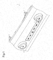
Fig. 1 is a perspective view of a switch device; -
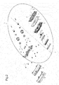
Fig. 2 is an exploded perspective view of the switch device; -
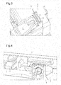
Fig. 3 is a partial perspective view of a switch assembly; -
Fig. 4 is a perspective view showing the surrounding of a breakable component; -
Figs. 5A and 5B are perspective views of an accommodation portion; -
Fig. 6A is a perspective view of a breakable component; -
Fig. 6B is a front view of the breakable component; and -
Fig. 7 is a partial cross-sectional view showing when the switch assembly falls off when an impact is received. - One embodiment of a switch device will now be described.
- As shown in
Fig. 1 , a switch device 1 according to one embodiment may be a heater controller switch device or an air conditioner controller switch device. The switch device 1 is directly or indirectly attached to a center console (not shown) of a vehicle by a plurality offasteners 2. The switch device 1 is an interior component of the vehicle. The switch device 1 includes at least oneknob 3. Theknob 3 is an example of a switch component projecting into the passenger compartment. - As shown in
Fig. 2 , the switch device 1 may be divided into anouter panel 4 supporting thefasteners 2, aswitch cover panel 5 including an ornamental surface, and aswitch assembly 6. Thepanels switch assembly 6 may be referred to as a switch main body. Theswitch cover panel 5 may include a liquid crystal display (LCD) window or an LCD panel. - The
switch assembly 6 includes a circuit board 7, abody 8, afirst housing shell 9, and asecond housing shell 10. A plurality of switch components including the circuit board 7 are arranged at or supported by predetermined locations of thebody 8. This assembles the switch components in thebody 8. Thebody 8 is located in an accommodation space formed by thefirst housing shell 9 and thesecond housing shell 10. Thefirst housing shell 9, thebody 8, and thesecond housing shell 10 are fastened byscrews 11 and integrated into a unit. - The
screws 11 inserted from screw insertion holes (not shown) of thesecond housing shell 10 extend through screw insertion holes of the circuit board 7 and thebody 8 and are fastened to threaded holes of thefirst housing shell 9. Thescrews 11 hold thebody 8, thefirst housing shell 9, and thesecond housing shell 10 as an integrated unit. - As shown in
Figs. 3 and 4 , when theswitch cover panel 5 is coupled to theouter panel 4,screw engagement portions 5a, which are parts of theswitch cover panel 5, are located between theswitch assembly 6 and theouter panel 4. Together with theswitch cover panel 5, theswitch assembly 6 is coupled to the outer panel 4 (switch mount) byscrews 13 and brittle plate-likebreakable components 12. Thus, theswitch assembly 6 falls off from theouter panel 4 when thescrews 13 are removed or when the brittlebreakable components 12 break. - As shown in
Fig. 4 ,accommodation portions 14 project from the outer edge of thefirst housing shell 9. Eachaccommodation portion 14 holds one of the plate-likebreakable components 12. One of thescrews 13 fastens a central portion of thebreakable component 12 to theaccommodation portion 14. Thescrew 13 engages the correspondingscrew engagement portion 5a of theswitch cover panel 5 through thebreakable component 12 and theaccommodation portion 14. - As shown in
Figs. 5A and 5B , eachaccommodation portion 14 includes a binder, which is formed by a plurality offirst holding pieces 15a and a plurality ofsecond holding pieces 15b, to hold the correspondingbreakable component 12 in the thicknesswise direction of thebreakable component 12. Thefirst holding pieces 15a contact or engage a first surface of thebreakable component 12. Thesecond holding pieces 15b contact or engage a second surface of thebreakable component 12. Theaccommodation portion 14 includes an entrance opening 14a at the upper edge. Thebreakable component 12 is press-fitted from the entrance opening 14a into between thefirst holding pieces 15a and thesecond holding pieces 15b and held on a stopper surface 14b. Each holdingpiece 15a may include arib 15r that locally presses the first surface of thebreakable component 12. - As shown in
Figs. 6A and 6B , eachbreakable component 12 includes anannular fastening portion 12a, an annular fall-off portion 12b, and one or more (e.g., four)brittle portions 12c. Thefastening portion 12a includes a central through hole that receives ascrew 13. The fall-off portion 12b is slightly larger than thefastening portion 12a and extends around thefastening portion 12a. Thebrittle portions 12c connect thefastening portion 12a and the fall-off portion 12b. The fall-off portion 12b forms the outline of thebreakable component 12. Thefastening portion 12a may be coaxial to or concentric to the fall-off portion 12b. Thebrittle portions 12c radially extend from the outer circumference of thefastening portion 12a to the inner circumference of the fall-off portion 12b at intervals of approximately 90° in the circumferential direction. Eachbrittle portion 12c may be referred to as a bridge. The outer circumference of the fall-off portion 12b includes twoparallel guide surfaces 12g, which are separated by the same distance from the center of the central through hole. The guide surfaces 12g set a coupling direction of thebreakable component 12 relative to theaccommodation portion 14 of thefirst housing shell 9. When thebreakable component 12 is held by theaccommodation portion 14, the fourbrittle portions 12c are generally located in the one thirty, four thirty, seven thirty, and ten thirty hour-hand positions of a clock face. The orientation of thebrittle portions 12c may be set so that the breakable component breaks as expected when receiving an impact to obtain the desired fall-off property. - As shown in
Fig. 5B , it is preferred that thesecond holding pieces 15b of theaccommodation portion 14 be formed around a through hole 14c that is separated from the entrance opening 14a. The through hole 14c is formed so that thesecond holding pieces 15b of theaccommodation portion 14 engage the fall-off portion 12b of thebreakable component 12 but not thefastening portion 12a of thebreakable component 12. - When the
brittle portions 12c of thebreakable component 12 break, the fall-off portion 12b of thebreakable component 12 remains in theaccommodation portion 14, and thefastening portion 12a is moved through the through hole 14c and released from theaccommodation portion 14. - The
breakable components 12 are discrete from theswitch assembly 6 and may be referred to as a breakable washer component or a breakable spacer component. The fall-off structure includes thebreakable component 12 and theaccommodation portion 14. - The operation of the fall-off structure for a switch will now be described.
- As shown in the upper section of
Fig. 7 , thescrews 13, which are inserted through thebreakable components 12, couple thefirst housing shell 9, which is a part of theswitch assembly 6, together with theswitch cover panel 5 to theouter panel 4. - When an impact indicated by upward arrows in
Fig. 7 is applied to theswitch assembly 6, thebrittle portions 12c of eachbreakable component 12 break. This separates thefastening portion 12a from the fall-off portion 12b in thebreakable component 12. Thefastening portion 12a of thebreakable component 12 remains fastened to theouter panel 4. The fall-off portion 12b of thebreakable component 12 falls off from theouter panel 4 together with theswitch assembly 6. Thebreakable component 12 is press-fitted to theaccommodation portion 14. Thus, the fall-off portion 12b is held by the holding pieces 15 when falling off together with theswitch assembly 6 including thefirst housing shell 9. As a result, the fall-offportions 12b of thebreakable components 12 are not scattered when thebreakable components 12 break. Theswitch assembly 6 falls off so that, for example, theknob 3 having the largest projection amount in theswitch assembly 6 satisfies the safety regulations that determine the maximum projection length. - After the
switch assembly 6 falls off, a replacement task is performed to replace thebreakable components 12 that have been broken by an impact with new ones. The serviceman performing the replacement removes fragments (fall-off portion 12b) from between the first andsecond holding pieces breakable component 12. The serviceman also removes thescrews 13 to remove fragments (fastening portions 12a) from theouter panel 4. - Then, the serviceman puts a new
breakable component 12 from the entrance opening 14a into eachaccommodation portion 14 and slides thebreakable component 12 to the stopper surface 14b. This couples the newbreakable component 12 to theaccommodation portion 14. After replacing thebreakable components 12, the serviceman couples theswitch assembly 6 together with theswitch cover panel 5 to theouter panel 4 with thescrews 13 inserted through the replacedbreakable components 12. This may reduce costs for repairing the switch device 1 after theswitch assembly 6 falls off. - The present embodiment has the advantages described below.
- (1) The brittle
breakable component 12, which is configured to break when an impact is applied to theswitch assembly 6, is a dedicate component independent from other components of theswitch assembly 6. In this configuration, when an impact is applied to theswitch assembly 6, thebreakable component 12 breaks and theswitch assembly 6 falls off from theouter panel 4. Each brokenbreakable component 12 is replaced with a new one after theswitch assembly 6 falls off. The repair unit is thebreakable components 12, which is small compared to thepanels body 8, thehousing shells - (2) The
switch assembly 6 includes theaccommodation portion 14, which includes the entrance opening 14a and stopper surface 14b for eachbreakable component 12. Theaccommodation portion 14 is configured to allow thebreakable component 12 to slidably move from the entrance opening 14a to the stopper surface 14b. In this configuration, thebreakable component 12 is moved in and coupled to theaccommodation portion 14. This simplifies the task for coupling thebreakable component 12 and the task for removing fragments of the brokenbreakable component 12. - (3) Each
breakable component 12 includes the guide surfaces 12g that set the coupling direction of thebreakable component 12 relative to the switch assembly 6 (accommodation portion 14 of the first housing shell 9). In this configuration, the guide surfaces 12g determine the coupling direction of thebreakable component 12. This couples thebreakable component 12 to the switch assembly 6 (accommodation portion 14 of the first housing shell 9) at the desired position in the desired orientation without mistakes in the orientation of thebreakable component 12. Thus, thebreakable component 12 breaks as expected when receiving an impact. This obtains the desired fall-off property. - (4) The switch assembly 6 (holding
pieces 15a in theaccommodation portion 14 of the first housing shell 9) includes theribs 15r that hold thebreakable components 12 under pressure. This configuration limits scattering of fragments of thebreakable components 12 when broken by an impact applied to theswitch assembly 6. Thus, thebreakable components 12 can be smoothly replaced. - (5) Each
breakable component 12 is press-fitted to and held by theswitch assembly 6. Thus, when theswitch assembly 6 is coupled to theswitch cover panel 5 by thebreakable component 12, theswitch assembly 6 can be separated from theouter panel 4. Also, as long as an impact is not applied to thebreakable component 12, stress produced when tightening thescrew 13 acts on only thefastening portion 12a, and no stress acts on the fall-off portion 12b. Thus, two different stresses do not act on thebreakable component 12. This limits breakage of thebrittle portion 12c that would be caused by a difference between stresses. - It should be apparent to those skilled in the art that the present invention may be embodied in many other specific forms without departing from the scope of the invention. Particularly, it should be understood that the present invention may be embodied in the following forms.
- All of the holding
pieces 15a do not have to include therib 15r. For example, therib 15r may be omitted from at least one of the holdingpieces 15a. Further, one holdingpiece 15a may include a plurality of theribs 15r. Theribs 15r may be omitted from all of the holdingpieces 15a. Instead of or in addition to the holdingpieces 15a, the holdingpieces 15b may include theribs 15r. Instead of or in addition to the switch assembly 6 (holding pieces 15), eachbreakable component 12 may include therib 15r. - Each
breakable component 12 may include only oneguide surface 12g instead of the twoguide surfaces 12g. Thebreakable component 12 may be a thin square plate. In this case, each straight side of the squarebreakable component 12 may function as theguide surface 12g. - Each
breakable component 12 may be a thin polygonal plate or a thin circular plate. - The
fastening portion 12a and the fall-off portion 12b of thebreakable component 12 may form a step in the thicknesswise direction. For example, when thebrittle portion 12c breaks, theswitch assembly 6 falls off so that the separation of thefastening portion 12a and the fall-off portion 12b eliminates the step. The projection amount of theknob 3 may be adjusted by setting a step in thebreakable component 12. - Each
breakable component 12 does not have to be press-fitted to and held by theswitch assembly 6 as long as the difference in the stresses generated in thefastening portion 12a and the fall-off portion 12b of thebreakable component 12 does not cause breakage of thebrittle portion 12c when thebreakable component 12 is free from an impact. For example, thescrews 13 may fasten thefastening portions 12a to theouter panel 4 and theswitch assembly 6 may be held between the fall-offportions 12b and theouter panel 4 to couple theswitch assembly 6 to theouter panel 4. In this case, it is desirable that the stress generated in the fall-off portion 12b be reduced when receiving an external force from theswitch assembly 6. - The switch device 1 is not limited to a heat controller switch device or an air conditioner controller device. The switch device 1 is not limited to an interior component located in a passenger compartment. The switch device 1 may be any switch device of which the maximum projection amount is regulated.
- The present disclosure includes the following examples.
- In one example, at least one of a switch assembly and a breakable component includes a rib that holds the breakable component in a press-fit state. This example limits scattering of breakable component fragments after the breakable components are broken by an impact applied to the switch assembly. Thus, the breakable component can be smoothly replaced.
- In another example, a switch assembly is coupled to a switch mount by a breakable component. The breakable component includes a fastening portion, which is fastened to the switch mount, and a fall-off portion, which falls off from the switch mount together with the switch assembly after breakage. The fastening portion and the fall-off portion are connected by a brittle portion that breaks when an impact is applied to the switch assembly. This example breaks the brittle portion of the breakable component and separates the fastening portion from the fall-off portion in the breakable component when an impact is applied to the switch assembly, which is coupled to the switch mount. In this case, the fastening portion of the breakable component remains fastened to the switch mount, and the fall-off portion of the breakable component falls off from the switch mount together with the switch assembly. This decreases the projection amount of the switch assembly.
- A certain embodiment discloses a switch device including a switch mount and a switch assembly coupled to the switch mount, wherein the switch assembly includes a circuit board, a housing shell that accommodates the circuit board, and a knob that projects from the housing shell, wherein the switch device includes a breakable spacer component located between the switch assembly and the switch mount, wherein the breakable spacer component is configured to break when an impact is applied to the switch assembly so that the switch assembly falls off from the switch mount.
- In an embodiment, the breakable spacer component is a breakable washer component for use with a fastener, such as a screw, that fastens the housing shell to the switch mount. In an embodiment, the breakable washer component includes a first annular portion that is directly or indirectly fastened to the switch mount by the fastener, a second annular portion that is coaxial to or concentric to the first annular portion and engaged in a removable manner with the switch assembly, and at least one brittle portion that bridges the first annular portion and the second annular portion. In an embodiment, the switch mount includes a binder disengaged from the first annular portion of the breakable spacer component and engaged with the second annular portion of the breakable spacer component, and the binder includes a fastener through hole formed so that the first annular portion, which is separated from the second annular portion when the brittle portion breaks, moves through the fastener through hole of the binder along a center axis of the first annular portion.
- The above description is intended to be illustrative, and not restrictive. For example, the above-described examples (or one or more aspects thereof) may be used in combination with each other. Other embodiments can be used, such as by one of ordinary skill in the art upon reviewing the above description. Also, in the above description, various features may be grouped together to streamline the disclosure. This should not be interpreted as intending that an unclaimed disclosed feature is essential to any claim. Rather, inventive subject matter may lie in less than all features of a particular disclosed embodiment. The scope of the invention should be determined with reference to the appended claims, along with the full scope of equivalents to which such claims are entitled.
Claims (7)
- Afall-off structure for a switch configured so that a switch assembly (6) including a plurality of switch components falls off from a switch mount (4) when an impact is received, the fall-off structure for a switch being characterized by:a breakable component (12) that has brittleness and is configured to break when an impact is applied to the switch assembly (6),wherein the breakable component (12) is a dedicated component independent from another component of the switch assembly (6).
- The fall-off structure according to claim 1, characterized in that the switch assembly (6) includes
an accommodation portion (14) including an entrance opening (14a) and a stopper surface (14b) and configured to allow the breakable component (12) to enter the entrance opening (14a) and slidably move to the stopper surface (14b). - The fall-off structure according to claim 1 or 2, characterized in that the breakable component (12) includes a guide surface (12g) configured to set a coupling direction of the breakable component (12) relative to the switch assembly (6).
- A switch device (1) including:a switch mount (4);a switch assembly (6) coupled to the switch mount (4), wherein the switch assembly (6) includes a circuit board (7), a housing shell (9, 10) that accommodates the circuit board (7), and a knob (3) that projects from the housing shell (9, 10); andthe switch device (1) being characterized by a breakable spacer component (12) located between the switch assembly (6) and the switch mount (4), wherein the breakable spacer component (12) is configured to break when an impact is applied to the switch assembly (6) so that the switch assembly (6) falls off from the switch mount (4).
- The switch device (1) according to claim 4, characterized in that the breakable spacer component (12) is a breakable washer component for use with a fastener (13) that fastens the housing shell (9, 10) to the switch mount (4).
- The switch device (1) according to claim 5, characterized in that the breakable washer component (12) includes
a first annular portion (12a) that is directly or indirectly fastened to the switch mount (4) by the fastener (13),
a second annular portion (12b) that is coaxial to or concentric to the first annular portion (12a) and engaged in a removable manner with the switch assembly (6), and
at least one brittle portion (12c) that bridges the first annular portion (12a) and the second annular portion (12b). - The switch device (1) according to claim 6, characterized in that
the switch mount (4) includes a binder (15) disengaged from the first annular portion (12a) of the breakable spacer component (12) and engaged with the second annular portion (12b) of the breakable spacer component (12), and
the binder (15) includes a fastener through hole (14c) formed so that the first annular portion (12a), which is separated from the second annular portion (12b) when the brittle portion (12c) breaks, moves through the fastener through hole (14c) of the binder (15) along a center axis of the first annular portion (12a).
Applications Claiming Priority (1)
| Application Number | Priority Date | Filing Date | Title |
|---|---|---|---|
| JP2014016029A JP5990549B2 (en) | 2014-01-30 | 2014-01-30 | Switch drop-off structure |
Publications (2)
| Publication Number | Publication Date |
|---|---|
| EP2902242A1 true EP2902242A1 (en) | 2015-08-05 |
| EP2902242B1 EP2902242B1 (en) | 2017-08-23 |
Family
ID=52354863
Family Applications (1)
| Application Number | Title | Priority Date | Filing Date |
|---|---|---|---|
| EP15151906.3A Active EP2902242B1 (en) | 2014-01-30 | 2015-01-21 | Fall-off structure for switch |
Country Status (2)
| Country | Link |
|---|---|
| EP (1) | EP2902242B1 (en) |
| JP (1) | JP5990549B2 (en) |
Cited By (2)
| Publication number | Priority date | Publication date | Assignee | Title |
|---|---|---|---|---|
| US10959323B1 (en) | 2019-09-06 | 2021-03-23 | Performance Motion Devices, Inc. | Over-torque protection features for mounting an electronic device to a heat dissipation object |
| US12535844B2 (en) | 2020-12-09 | 2026-01-27 | Crouzet | Paddle button |
Families Citing this family (2)
| Publication number | Priority date | Publication date | Assignee | Title |
|---|---|---|---|---|
| JP6619275B2 (en) * | 2016-03-24 | 2019-12-11 | 小島プレス工業株式会社 | In-vehicle accessory operation device |
| EP3861217A1 (en) * | 2018-10-04 | 2021-08-11 | RENAULT s.a.s. | Mounting device configured to be broken and breakable for assembling two parts of a motor vehicle |
Citations (5)
| Publication number | Priority date | Publication date | Assignee | Title |
|---|---|---|---|---|
| DE6933661U (en) * | 1969-08-12 | 1969-12-04 | Rau Swf Autozubehoer | DEVICE FOR FASTENING AN EQUIPMENT, IN PARTICULAR A SWITCH OR THE SAME, IN THE DASHBOARD OF A MOTOR VEHICLE. |
| US4051916A (en) * | 1975-12-22 | 1977-10-04 | Nissan Motor Company, Limited | Apparatus for mounting instrument to instrument panel in motor vehicle |
| JP2003011744A (en) | 2001-04-04 | 2003-01-15 | Halla Aircon Co Ltd | Mode switch assembly for vehicle with shock absorbing device |
| EP1661771A1 (en) * | 2004-11-29 | 2006-05-31 | Alps Electric Co., Ltd. | Operation panel unit |
| CN201951261U (en) * | 2011-03-09 | 2011-08-31 | 河北中兴汽车制造有限公司 | Security protection structure for automobile controller |
Family Cites Families (3)
| Publication number | Priority date | Publication date | Assignee | Title |
|---|---|---|---|---|
| JP2008041654A (en) * | 2006-07-12 | 2008-02-21 | Sumitomo Wiring Syst Ltd | Switch for vehicle |
| JP5292903B2 (en) * | 2008-04-17 | 2013-09-18 | パナソニック株式会社 | Switch device for vehicle |
| JP2011054466A (en) * | 2009-09-03 | 2011-03-17 | Toyota Auto Body Co Ltd | Operation knob for vehicle |
-
2014
- 2014-01-30 JP JP2014016029A patent/JP5990549B2/en active Active
-
2015
- 2015-01-21 EP EP15151906.3A patent/EP2902242B1/en active Active
Patent Citations (5)
| Publication number | Priority date | Publication date | Assignee | Title |
|---|---|---|---|---|
| DE6933661U (en) * | 1969-08-12 | 1969-12-04 | Rau Swf Autozubehoer | DEVICE FOR FASTENING AN EQUIPMENT, IN PARTICULAR A SWITCH OR THE SAME, IN THE DASHBOARD OF A MOTOR VEHICLE. |
| US4051916A (en) * | 1975-12-22 | 1977-10-04 | Nissan Motor Company, Limited | Apparatus for mounting instrument to instrument panel in motor vehicle |
| JP2003011744A (en) | 2001-04-04 | 2003-01-15 | Halla Aircon Co Ltd | Mode switch assembly for vehicle with shock absorbing device |
| EP1661771A1 (en) * | 2004-11-29 | 2006-05-31 | Alps Electric Co., Ltd. | Operation panel unit |
| CN201951261U (en) * | 2011-03-09 | 2011-08-31 | 河北中兴汽车制造有限公司 | Security protection structure for automobile controller |
Cited By (2)
| Publication number | Priority date | Publication date | Assignee | Title |
|---|---|---|---|---|
| US10959323B1 (en) | 2019-09-06 | 2021-03-23 | Performance Motion Devices, Inc. | Over-torque protection features for mounting an electronic device to a heat dissipation object |
| US12535844B2 (en) | 2020-12-09 | 2026-01-27 | Crouzet | Paddle button |
Also Published As
| Publication number | Publication date |
|---|---|
| EP2902242B1 (en) | 2017-08-23 |
| JP2015140164A (en) | 2015-08-03 |
| JP5990549B2 (en) | 2016-09-14 |
Similar Documents
| Publication | Publication Date | Title |
|---|---|---|
| EP2902242B1 (en) | Fall-off structure for switch | |
| KR101666235B1 (en) | Device for fastening a vehicle interior trim panel | |
| WO2007005658A3 (en) | Standby display aircraft management system | |
| EP3147164B1 (en) | Fixed type apparatus for destroying glass | |
| JP6338932B2 (en) | Cup holder | |
| US20030141738A1 (en) | Automobile instrument panel assembly | |
| WO2018168265A1 (en) | Attachment structure with removal mechanism for on-vehicle device | |
| WO2016038861A1 (en) | Mounting structure | |
| CN102317116B (en) | Part mounting structure | |
| US10953812B2 (en) | Vehicle-mounted device | |
| US10823222B2 (en) | Assembly and method for securing a fastening element | |
| US10427621B2 (en) | Vehicle tether clip | |
| JP4746625B2 (en) | Vehicle liners and interior lighting systems and fixtures | |
| KR101405715B1 (en) | Fastener for vehicle | |
| CN112047222A (en) | Removable panel for elevator panel assembly | |
| WO2015083334A1 (en) | Operation device | |
| WO2006117036A3 (en) | Device carrier for actuating an electric coupling and a control element | |
| US9831571B2 (en) | Relay terminal block | |
| DE102012023324B4 (en) | Arrangement for attaching a built-in device | |
| CN100466887C (en) | appliance panel | |
| KR200491255Y1 (en) | An instrument panel assembly including a notch | |
| EP3567265A1 (en) | Apparatus configured to be installed in a vehicle | |
| DE102014104534B4 (en) | Trim part for an instrument panel of a motor vehicle and instrument panel | |
| CN216731634U (en) | Vehicle buckle screwdriver | |
| US12267969B2 (en) | Display apparatus |
Legal Events
| Date | Code | Title | Description |
|---|---|---|---|
| PUAI | Public reference made under article 153(3) epc to a published international application that has entered the european phase |
Free format text: ORIGINAL CODE: 0009012 |
|
| 17P | Request for examination filed |
Effective date: 20150121 |
|
| AK | Designated contracting states |
Kind code of ref document: A1 Designated state(s): AL AT BE BG CH CY CZ DE DK EE ES FI FR GB GR HR HU IE IS IT LI LT LU LV MC MK MT NL NO PL PT RO RS SE SI SK SM TR |
|
| AX | Request for extension of the european patent |
Extension state: BA ME |
|
| GRAP | Despatch of communication of intention to grant a patent |
Free format text: ORIGINAL CODE: EPIDOSNIGR1 |
|
| STAA | Information on the status of an ep patent application or granted ep patent |
Free format text: STATUS: GRANT OF PATENT IS INTENDED |
|
| RIC1 | Information provided on ipc code assigned before grant |
Ipc: B60K 37/06 20060101AFI20170302BHEP Ipc: B60R 21/09 20060101ALI20170302BHEP Ipc: H01H 3/02 20060101ALN20170302BHEP Ipc: B60R 21/055 20060101ALI20170302BHEP Ipc: H01H 3/08 20060101ALI20170302BHEP |
|
| INTG | Intention to grant announced |
Effective date: 20170321 |
|
| GRAS | Grant fee paid |
Free format text: ORIGINAL CODE: EPIDOSNIGR3 |
|
| GRAA | (expected) grant |
Free format text: ORIGINAL CODE: 0009210 |
|
| STAA | Information on the status of an ep patent application or granted ep patent |
Free format text: STATUS: THE PATENT HAS BEEN GRANTED |
|
| AK | Designated contracting states |
Kind code of ref document: B1 Designated state(s): AL AT BE BG CH CY CZ DE DK EE ES FI FR GB GR HR HU IE IS IT LI LT LU LV MC MK MT NL NO PL PT RO RS SE SI SK SM TR |
|
| REG | Reference to a national code |
Ref country code: GB Ref legal event code: FG4D |
|
| REG | Reference to a national code |
Ref country code: CH Ref legal event code: EP |
|
| REG | Reference to a national code |
Ref country code: AT Ref legal event code: REF Ref document number: 920934 Country of ref document: AT Kind code of ref document: T Effective date: 20170915 |
|
| REG | Reference to a national code |
Ref country code: IE Ref legal event code: FG4D |
|
| REG | Reference to a national code |
Ref country code: DE Ref legal event code: R096 Ref document number: 602015004189 Country of ref document: DE |
|
| REG | Reference to a national code |
Ref country code: NL Ref legal event code: MP Effective date: 20170823 |
|
| REG | Reference to a national code |
Ref country code: LT Ref legal event code: MG4D |
|
| REG | Reference to a national code |
Ref country code: AT Ref legal event code: MK05 Ref document number: 920934 Country of ref document: AT Kind code of ref document: T Effective date: 20170823 |
|
| REG | Reference to a national code |
Ref country code: FR Ref legal event code: PLFP Year of fee payment: 4 |
|
| PG25 | Lapsed in a contracting state [announced via postgrant information from national office to epo] |
Ref country code: NO Free format text: LAPSE BECAUSE OF FAILURE TO SUBMIT A TRANSLATION OF THE DESCRIPTION OR TO PAY THE FEE WITHIN THE PRESCRIBED TIME-LIMIT Effective date: 20171123 Ref country code: FI Free format text: LAPSE BECAUSE OF FAILURE TO SUBMIT A TRANSLATION OF THE DESCRIPTION OR TO PAY THE FEE WITHIN THE PRESCRIBED TIME-LIMIT Effective date: 20170823 Ref country code: HR Free format text: LAPSE BECAUSE OF FAILURE TO SUBMIT A TRANSLATION OF THE DESCRIPTION OR TO PAY THE FEE WITHIN THE PRESCRIBED TIME-LIMIT Effective date: 20170823 Ref country code: SE Free format text: LAPSE BECAUSE OF FAILURE TO SUBMIT A TRANSLATION OF THE DESCRIPTION OR TO PAY THE FEE WITHIN THE PRESCRIBED TIME-LIMIT Effective date: 20170823 Ref country code: NL Free format text: LAPSE BECAUSE OF FAILURE TO SUBMIT A TRANSLATION OF THE DESCRIPTION OR TO PAY THE FEE WITHIN THE PRESCRIBED TIME-LIMIT Effective date: 20170823 Ref country code: LT Free format text: LAPSE BECAUSE OF FAILURE TO SUBMIT A TRANSLATION OF THE DESCRIPTION OR TO PAY THE FEE WITHIN THE PRESCRIBED TIME-LIMIT Effective date: 20170823 Ref country code: AT Free format text: LAPSE BECAUSE OF FAILURE TO SUBMIT A TRANSLATION OF THE DESCRIPTION OR TO PAY THE FEE WITHIN THE PRESCRIBED TIME-LIMIT Effective date: 20170823 |
|
| PG25 | Lapsed in a contracting state [announced via postgrant information from national office to epo] |
Ref country code: ES Free format text: LAPSE BECAUSE OF FAILURE TO SUBMIT A TRANSLATION OF THE DESCRIPTION OR TO PAY THE FEE WITHIN THE PRESCRIBED TIME-LIMIT Effective date: 20170823 Ref country code: LV Free format text: LAPSE BECAUSE OF FAILURE TO SUBMIT A TRANSLATION OF THE DESCRIPTION OR TO PAY THE FEE WITHIN THE PRESCRIBED TIME-LIMIT Effective date: 20170823 Ref country code: RS Free format text: LAPSE BECAUSE OF FAILURE TO SUBMIT A TRANSLATION OF THE DESCRIPTION OR TO PAY THE FEE WITHIN THE PRESCRIBED TIME-LIMIT Effective date: 20170823 Ref country code: BG Free format text: LAPSE BECAUSE OF FAILURE TO SUBMIT A TRANSLATION OF THE DESCRIPTION OR TO PAY THE FEE WITHIN THE PRESCRIBED TIME-LIMIT Effective date: 20171123 Ref country code: IS Free format text: LAPSE BECAUSE OF FAILURE TO SUBMIT A TRANSLATION OF THE DESCRIPTION OR TO PAY THE FEE WITHIN THE PRESCRIBED TIME-LIMIT Effective date: 20171223 Ref country code: GR Free format text: LAPSE BECAUSE OF FAILURE TO SUBMIT A TRANSLATION OF THE DESCRIPTION OR TO PAY THE FEE WITHIN THE PRESCRIBED TIME-LIMIT Effective date: 20171124 Ref country code: PL Free format text: LAPSE BECAUSE OF FAILURE TO SUBMIT A TRANSLATION OF THE DESCRIPTION OR TO PAY THE FEE WITHIN THE PRESCRIBED TIME-LIMIT Effective date: 20170823 |
|
| PG25 | Lapsed in a contracting state [announced via postgrant information from national office to epo] |
Ref country code: DK Free format text: LAPSE BECAUSE OF FAILURE TO SUBMIT A TRANSLATION OF THE DESCRIPTION OR TO PAY THE FEE WITHIN THE PRESCRIBED TIME-LIMIT Effective date: 20170823 Ref country code: RO Free format text: LAPSE BECAUSE OF FAILURE TO SUBMIT A TRANSLATION OF THE DESCRIPTION OR TO PAY THE FEE WITHIN THE PRESCRIBED TIME-LIMIT Effective date: 20170823 Ref country code: CZ Free format text: LAPSE BECAUSE OF FAILURE TO SUBMIT A TRANSLATION OF THE DESCRIPTION OR TO PAY THE FEE WITHIN THE PRESCRIBED TIME-LIMIT Effective date: 20170823 |
|
| REG | Reference to a national code |
Ref country code: DE Ref legal event code: R097 Ref document number: 602015004189 Country of ref document: DE |
|
| PG25 | Lapsed in a contracting state [announced via postgrant information from national office to epo] |
Ref country code: SK Free format text: LAPSE BECAUSE OF FAILURE TO SUBMIT A TRANSLATION OF THE DESCRIPTION OR TO PAY THE FEE WITHIN THE PRESCRIBED TIME-LIMIT Effective date: 20170823 Ref country code: EE Free format text: LAPSE BECAUSE OF FAILURE TO SUBMIT A TRANSLATION OF THE DESCRIPTION OR TO PAY THE FEE WITHIN THE PRESCRIBED TIME-LIMIT Effective date: 20170823 Ref country code: SM Free format text: LAPSE BECAUSE OF FAILURE TO SUBMIT A TRANSLATION OF THE DESCRIPTION OR TO PAY THE FEE WITHIN THE PRESCRIBED TIME-LIMIT Effective date: 20170823 Ref country code: IT Free format text: LAPSE BECAUSE OF FAILURE TO SUBMIT A TRANSLATION OF THE DESCRIPTION OR TO PAY THE FEE WITHIN THE PRESCRIBED TIME-LIMIT Effective date: 20170823 |
|
| PLBE | No opposition filed within time limit |
Free format text: ORIGINAL CODE: 0009261 |
|
| STAA | Information on the status of an ep patent application or granted ep patent |
Free format text: STATUS: NO OPPOSITION FILED WITHIN TIME LIMIT |
|
| 26N | No opposition filed |
Effective date: 20180524 |
|
| PG25 | Lapsed in a contracting state [announced via postgrant information from national office to epo] |
Ref country code: SI Free format text: LAPSE BECAUSE OF FAILURE TO SUBMIT A TRANSLATION OF THE DESCRIPTION OR TO PAY THE FEE WITHIN THE PRESCRIBED TIME-LIMIT Effective date: 20170823 |
|
| REG | Reference to a national code |
Ref country code: CH Ref legal event code: PL |
|
| PG25 | Lapsed in a contracting state [announced via postgrant information from national office to epo] |
Ref country code: LU Free format text: LAPSE BECAUSE OF NON-PAYMENT OF DUE FEES Effective date: 20180121 |
|
| REG | Reference to a national code |
Ref country code: IE Ref legal event code: MM4A |
|
| REG | Reference to a national code |
Ref country code: BE Ref legal event code: MM Effective date: 20180131 |
|
| PG25 | Lapsed in a contracting state [announced via postgrant information from national office to epo] |
Ref country code: LI Free format text: LAPSE BECAUSE OF NON-PAYMENT OF DUE FEES Effective date: 20180131 Ref country code: CH Free format text: LAPSE BECAUSE OF NON-PAYMENT OF DUE FEES Effective date: 20180131 Ref country code: BE Free format text: LAPSE BECAUSE OF NON-PAYMENT OF DUE FEES Effective date: 20180131 |
|
| PG25 | Lapsed in a contracting state [announced via postgrant information from national office to epo] |
Ref country code: IE Free format text: LAPSE BECAUSE OF NON-PAYMENT OF DUE FEES Effective date: 20180121 |
|
| PG25 | Lapsed in a contracting state [announced via postgrant information from national office to epo] |
Ref country code: MC Free format text: LAPSE BECAUSE OF FAILURE TO SUBMIT A TRANSLATION OF THE DESCRIPTION OR TO PAY THE FEE WITHIN THE PRESCRIBED TIME-LIMIT Effective date: 20170823 |
|
| GBPC | Gb: european patent ceased through non-payment of renewal fee |
Effective date: 20190121 |
|
| PG25 | Lapsed in a contracting state [announced via postgrant information from national office to epo] |
Ref country code: GB Free format text: LAPSE BECAUSE OF NON-PAYMENT OF DUE FEES Effective date: 20190121 |
|
| PG25 | Lapsed in a contracting state [announced via postgrant information from national office to epo] |
Ref country code: MT Free format text: LAPSE BECAUSE OF NON-PAYMENT OF DUE FEES Effective date: 20180121 |
|
| PG25 | Lapsed in a contracting state [announced via postgrant information from national office to epo] |
Ref country code: TR Free format text: LAPSE BECAUSE OF FAILURE TO SUBMIT A TRANSLATION OF THE DESCRIPTION OR TO PAY THE FEE WITHIN THE PRESCRIBED TIME-LIMIT Effective date: 20170823 |
|
| PG25 | Lapsed in a contracting state [announced via postgrant information from national office to epo] |
Ref country code: PT Free format text: LAPSE BECAUSE OF FAILURE TO SUBMIT A TRANSLATION OF THE DESCRIPTION OR TO PAY THE FEE WITHIN THE PRESCRIBED TIME-LIMIT Effective date: 20170823 |
|
| PG25 | Lapsed in a contracting state [announced via postgrant information from national office to epo] |
Ref country code: CY Free format text: LAPSE BECAUSE OF FAILURE TO SUBMIT A TRANSLATION OF THE DESCRIPTION OR TO PAY THE FEE WITHIN THE PRESCRIBED TIME-LIMIT Effective date: 20170823 Ref country code: HU Free format text: LAPSE BECAUSE OF FAILURE TO SUBMIT A TRANSLATION OF THE DESCRIPTION OR TO PAY THE FEE WITHIN THE PRESCRIBED TIME-LIMIT; INVALID AB INITIO Effective date: 20150121 Ref country code: MK Free format text: LAPSE BECAUSE OF NON-PAYMENT OF DUE FEES Effective date: 20170823 |
|
| PG25 | Lapsed in a contracting state [announced via postgrant information from national office to epo] |
Ref country code: AL Free format text: LAPSE BECAUSE OF FAILURE TO SUBMIT A TRANSLATION OF THE DESCRIPTION OR TO PAY THE FEE WITHIN THE PRESCRIBED TIME-LIMIT Effective date: 20170823 |
|
| REG | Reference to a national code |
Ref country code: DE Ref legal event code: R079 Ref document number: 602015004189 Country of ref document: DE Free format text: PREVIOUS MAIN CLASS: B60K0037060000 Ipc: B60K0035100000 |
|
| PGFP | Annual fee paid to national office [announced via postgrant information from national office to epo] |
Ref country code: FR Payment date: 20251128 Year of fee payment: 12 |
|
| PGFP | Annual fee paid to national office [announced via postgrant information from national office to epo] |
Ref country code: DE Payment date: 20251203 Year of fee payment: 12 |