EP3567265A1 - Apparatus configured to be installed in a vehicle - Google Patents
Apparatus configured to be installed in a vehicle Download PDFInfo
- Publication number
- EP3567265A1 EP3567265A1 EP19172555.5A EP19172555A EP3567265A1 EP 3567265 A1 EP3567265 A1 EP 3567265A1 EP 19172555 A EP19172555 A EP 19172555A EP 3567265 A1 EP3567265 A1 EP 3567265A1
- Authority
- EP
- European Patent Office
- Prior art keywords
- impact
- absorbing portion
- impact absorbing
- support member
- protrusion
- Prior art date
- Legal status (The legal status is an assumption and is not a legal conclusion. Google has not performed a legal analysis and makes no representation as to the accuracy of the status listed.)
- Granted
Links
- 238000010008 shearing Methods 0.000 claims abstract description 18
- 230000004048 modification Effects 0.000 description 9
- 238000012986 modification Methods 0.000 description 9
- 238000003780 insertion Methods 0.000 description 4
- 230000037431 insertion Effects 0.000 description 4
- 238000010521 absorption reaction Methods 0.000 description 3
- 239000000463 material Substances 0.000 description 3
- XEEYBQQBJWHFJM-UHFFFAOYSA-N Iron Chemical compound [Fe] XEEYBQQBJWHFJM-UHFFFAOYSA-N 0.000 description 2
- 229910000838 Al alloy Inorganic materials 0.000 description 1
- 229910001297 Zn alloy Inorganic materials 0.000 description 1
- 229910045601 alloy Inorganic materials 0.000 description 1
- 239000000956 alloy Substances 0.000 description 1
- 230000003247 decreasing effect Effects 0.000 description 1
- 230000001419 dependent effect Effects 0.000 description 1
- 230000000694 effects Effects 0.000 description 1
- 229910052742 iron Inorganic materials 0.000 description 1
- 239000004973 liquid crystal related substance Substances 0.000 description 1
- 229910052751 metal Inorganic materials 0.000 description 1
- 239000002184 metal Substances 0.000 description 1
- 238000000034 method Methods 0.000 description 1
- 230000002265 prevention Effects 0.000 description 1
Images


Classifications
-
- B—PERFORMING OPERATIONS; TRANSPORTING
- B60—VEHICLES IN GENERAL
- B60R—VEHICLES, VEHICLE FITTINGS, OR VEHICLE PARTS, NOT OTHERWISE PROVIDED FOR
- B60R11/00—Arrangements for holding or mounting articles, not otherwise provided for
- B60R11/06—Arrangements for holding or mounting articles, not otherwise provided for for tools or spare parts
-
- F—MECHANICAL ENGINEERING; LIGHTING; HEATING; WEAPONS; BLASTING
- F16—ENGINEERING ELEMENTS AND UNITS; GENERAL MEASURES FOR PRODUCING AND MAINTAINING EFFECTIVE FUNCTIONING OF MACHINES OR INSTALLATIONS; THERMAL INSULATION IN GENERAL
- F16B—DEVICES FOR FASTENING OR SECURING CONSTRUCTIONAL ELEMENTS OR MACHINE PARTS TOGETHER, e.g. NAILS, BOLTS, CIRCLIPS, CLAMPS, CLIPS OR WEDGES; JOINTS OR JOINTING
- F16B5/00—Joining sheets or plates, e.g. panels, to one another or to strips or bars parallel to them
- F16B5/02—Joining sheets or plates, e.g. panels, to one another or to strips or bars parallel to them by means of fastening members using screw-thread
- F16B5/0241—Joining sheets or plates, e.g. panels, to one another or to strips or bars parallel to them by means of fastening members using screw-thread with the possibility for the connection to absorb deformation, e.g. thermal or vibrational
Abstract
Description
- The present disclosure relates to an apparatus configured to be installed in a vehicle and capable of absorbing an impact force acting on an apparatus main body by moving the apparatus main body with respect to a support member, and to a vehicle comprising such apparatus.
-
JP 2013-198330 A - In this support structure, a bracket having mounting holes protrudes integrally from a side of the equipment box, and bolts inserted in the mounting holes are fastened to the support member, and thus the equipment box is secured to the support member. The bracket has a thin part between the equipment box and the mounting holes so that, when more than a certain load is applied to the equipment box, the bracket is broken at the thin part.
-
JP 2002-50880 A - In this impact absorption structure, an internal apparatus is disposed between opposing chassis, the chassis have screw insertion holes, and the internal apparatus has screw holes. Screws inserting in the screw insertion holes are screwed in the screw holes, so that the internal apparatus is secured between the opposing chassis. Each chassis has backup holes next to the screw insertion holes and grooves for decreasing the distance between each screw insertion hole and each backup hole. Thus, when an impact exceeding the fastening force of the screws acts on the internal apparatus or the chassis, the screws deform the grooves to move to the backup holes so that the impact is absorbed.
- The support structure disclosed in
JP 2013-198330 A - The impact absorption structure disclosed in
JP 2002-50880 A - An object of the present disclosure is to provide an apparatus configured to be installed in a vehicle and which is capable of absorbing an impact force acting on an apparatus main body and in which the impact force to be absorbed can be set to an optimum value in designing.
- The invention relates to an apparatus configured to be installed in a vehicle and a vehicle comprising such apparatus according to the appended claims. Embodiments are disclosed in the dependent claims.
- An apparatus configured to be installed in a vehicle according to an aspect of the present disclosure includes an impact absorbing portion that is part of an apparatus main body configured to be installed in a vehicle and a support member to which the impact absorbing portion is fixed. The apparatus is characterized in that an opposing fixing member, a fastening member that fastens the support member and the opposing fixing member together, and an opening in the impact absorbing portion in which the fastening member is inserted are provided. The support member and the opposing fixing member are fastened together by the fastening member, with the impact absorbing portion interposed between the support member and the opposing fixing member. A moving clearance is provided in an impact acting direction between the opening and the fastening member. A protrusion is provided on one of the opposing fixing member and the impact absorbing portion, and a recess is provided in another of the opposing fixing member and the impact absorbing portion, or a protrusion is provided on one of the support member and the impact absorbing portion, and a recess is provided in another of the support member and the impact absorbing portion. The protrusion and the recess are fitted to position the impact absorbing portion and the support member in the impact acting direction. The protrusion is configured to be separated when a shearing force in the impact acting direction acts on the protrusion.
- The apparatus according to an embodiment is characterized in that the protrusion is provided on the opposing fixing member, and a shearing strength per unit cross-sectional area against a shearing force is smaller in the opposing fixing member than in the impact absorbing portion and the support member.
- The apparatus according to an embodiment is characterized in that the protrusion is smaller in width in the impact acting direction than in length in a direction perpendicular to the impact acting direction, and the protrusion is configured to be separated by a shearing force directed in the width.
- The apparatus according to an embodiment is characterized in that the moving clearance is provided between the opening and the fastening member in all directions in a plane perpendicular to an axis of the fastening member, and the protrusion is configured to be separated by a shearing force in any direction in the plane.
- In an apparatus according to an embodiment of the present disclosure, an opposing fixing member and a support member are fastened to each other by a fastening member, with an impact absorbing portion interposed therebetween, and the opposing fixing member or the support member and the impact absorbing portion are positioned by fitting a protrusion and a recess. This allows high-accuracy positioning of the apparatus main body to the support member, preventing backlash and movement of the apparatus main body until a predetermined impact force acts.
- If more than a predetermined impact force acts on the apparatus main body, the protrusion is separated by a shearing force to move the apparatus main body, thereby absorbing the impact. Appropriately setting the material and the cross-sectional area of the protrusion facilitates setting an impact force to be absorbed, that is, impact resistance, in designing by separating the protrusion.
-
Fig. 1 is a perspective view of an apparatus according to an embodiment of the present disclosure viewed from the front; -
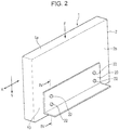
Fig. 2 is a perspective view of the apparatus according to an embodiment of the present disclosure viewed from the back; -
Fig. 3 is an exploded perspective view of the major components of the apparatus according to an embodiment of the present disclosure viewed from the back; -
Fig. 4A is an enlarged cross-sectional view of the apparatus inFig. 2 taken along line IV-IV, illustrating a state before an impact acts; -
Fig. 4B is an enlarged cross-sectional view of the apparatus taken along line IV-IV, illustrating a state after an impact acts; -
Fig. 5 is a back view of an apparatus of a modification of the present disclosure; -
Fig. 6 is an enlarged cross-sectional view of an apparatus of a modification, illustrating the same part as inFig. 4A ; -
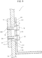
Fig. 7 is an enlarged cross-sectional view of an apparatus of a modification, illustrating the same part as inFig. 4A ; and -
Fig. 8 is an enlarged cross-sectional view of an apparatus of a modification, illustrating the same part as inFig. 4A . -
Figs. 1 and2 illustrate anapparatus 1 configured to be installed in a vehicle according to an embodiment of the present disclosure in the following designated shortly "in-vehicle apparatus". Generally, the apparatus according to the invention is for example a display device configured to be installed in a vehicle. - The in-
vehicle apparatus 1 generally includes an apparatusmain body 1a configured to be installed in a vehicle. The apparatusmain body 1a includes achassis 2 and adisplay cell 3 in thechassis 2. Examples of thedisplay cell 3 include a color liquid-crystal display cell and an electroluminescent display cell. Adisplay screen 3a of thedisplay cell 3 is exposed from an opening 2a of thechassis 2 facing the vehicle compartment. As illustrated inFig. 2 , a lower part of aback surface 2b of thechassis 2 opposite to thedisplay screen 3a serves as animpact absorbing portion 10. Theimpact absorbing portion 10 is fixed to asupport member 20. Thesupport member 20 is a support bracket and is made of a metal plate. Thesupport member 20 is fixed to the inside or the front surface of a dashboard of an instrument panel at the front of the vehicle compartment. Thedisplay screen 3a faces the vehicle interior. Alternatively, thesupport member 20 may be mounted on a movable table of a moving mechanism that moves up and down or back and forth from the dashboard or the instrument panel. -
Fig. 3 illustrates the structure of theimpact absorbing portion 10. Theimpact absorbing portion 10 is part of theback surface 2b of thechassis 2 constituting the apparatusmain body 1a. Alternatively, theimpact absorbing portion 10 may be separate from the apparatusmain body 1a and may be fixed to thechassis 2 by screwing or the like. An impact acting direction Y is assumed to be downward inFigs. 1 and2 . The in-vehicle apparatus 1 according to the embodiment illustrated inFigs. 1 and2 is configured, if an impact force F greater than a predetermined value is applied between theimpact absorbing portion 10 and thesupport member 20 in a downward impact acting direction Y, to absorb and reduce the impact force F. The impact acting direction Y assumed is not limited to the downward direction and may be any direction depending on the placement position of the in-vehicle apparatus 1 in the vehicle component or the kind of the in-vehicle apparatus 1. The relative position and the orientation of theimpact absorbing portion 10 and thesupport member 20 are set according to the assumed impact acting direction Y. - As illustrated in
Fig. 3 , theimpact absorbing portion 10 has anopening 11. Theopening 11 is a long hole whose length extends in the impact acting direction Y. A pair ofrecesses 12 are provided in aninner surface 10a of theimpact absorbing portion 10 facing inward of thechassis 2. As illustrated inFig. 4A , the recesses 12a are formed at a predetermined depth from theinner surface 10a. The pair ofrecesses 12 are positioned above and below theopening 11, with a space therebetween in the impact acting direction Y. Eachrecess 12 is small in width W1 in the impact acting direction Y and is sufficiently larger in width W2 in the X-direction perpendicular to the impact acting direction Y than the width W1. - As illustrated in
Fig. 3 , thechassis 2 has therein an opposing fixingmember 15 that is in contact with theinner surface 10a of theimpact absorbing portion 10 and that opposes thesupport member 20, with theimpact absorbing portion 10 therebetween. The opposing fixingmember 15 has a pair of internal thread holes. The internal thread holes 16 are disposed, with a certain distance therebetween in the impact acting direction Y. The opposing fixingmember 15 has a pair ofprotrusions 17 protruding integrally from an opposingsurface 15a opposing theimpact absorbing portion 10. Theupper protrusion 17 is provided above the upperinternal thread hole 16, and thelower protrusion 17 is provided below the lowerinternal thread hole 16. Thus, the pair ofprotrusions 17 are spaced apart from each other in the impact acting direction Y. - Each
protrusion 17 is small in thickness T in the impact acting direction Y and is sufficiently larger in length L in the X-direction perpendicular to the impact acting direction Y than the thickness T. The thickness T and the length L of theprotrusions 17 are respectively substantially equal to the width W1 and the width W2 of therecesses 12. As illustrated inFig. 4A , when theprotrusions 17 are fitted in therecesses 12 into the fitted state, the opposing fixingmember 15 and theimpact absorbing portion 10 are positioned without relatively moving in the impact acting direction Y and the X-direction perpendicular to the impact acting direction Y. - The opposing fixing
member 15 is made of an alloy, such as an aluminum alloy or a zinc alloy. Theimpact absorbing portion 10 and thesupport member 20 are made of iron or an allow. It is assumed that protrusions with the same size as theprotrusions 17 are formed on the opposing fixingmember 15, theimpact absorbing portion 10, or thesupport member 20. The materials of the opposing fixingmember 15, theimpact absorbing portion 10, and thesupport member 20 may be selected so that the break strength against a shearing force in the direction of the thickness T of each protrusion is preferably smaller in the opposing fixingmember 15 than in theimpact absorbing portion 10 and thesupport member 20. In other words, it is preferable that the break strength of the opposing fixingmember 15 per unit cross-sectional area against the shearing force is smaller than the break strength of theimpact absorbing portion 10 and thesupport member 20. - As illustrated in
Fig. 3 , thesupport member 20 has a pair of fixingholes 21 spaced in the impact acting direction Y. Fasteningmembers 22 are inserted in the corresponding fixing holes 21. Thefastening members 22 are fixing screws or fixing bolts. InFigs. 4A and 4B , awasher 23 is disposed between the head of thefastening member 22 and thesupport member 20 but is not illustrated inFig. 3 . Thefastening member 22 may be constituted by a fixing bolt and a nut or may be a press-fit pin or a lock pin to be fitted in the opposing fixingmember 15. -
Fig. 4A illustrates a cross-section structure in which theimpact absorbing portion 10, thesupport member 20, and the opposing fixingmember 15 are combined. The opposing fixingmember 15 is disposed on theinner surface 10a of theimpact absorbing portion 10, and theprotrusions 17 are fitted in the corresponding recesses 12. Thefastening members 22 are inserted in the fixing holes 21, with theback surface 2b of thechassis 2 in contact with thesupport member 20, pass through theopening 11 of theimpact absorbing portion 10, and theexternal threads 22a of thefastening members 22 are screwed in the internal thread holes 16 of the opposing fixingmember 15. Theprotrusions 17 and therecesses 12 are fitted, so that the opposing fixingmember 15 is positioned and fixed to theimpact absorbing portion 10 in the impact acting direction Y and the X-direction perpendicular to the impact acting direction Y. Since the opposing fixingmember 15 and thesupport member 20 are fixed to each other with thefastening members 22, theimpact absorbing portion 10, which is part of the apparatusmain body 1a, and thesupport member 20 are also positioned and fixed in the impact acting direction Y and the X-direction. A moving clearance δ is provided in the impact acting direction Y between theopening 11 and thefastening member 22, with theimpact absorbing portion 10, thesupport member 20, and the opposing fixingmember 15 combined. - When a force in the impact acting direction Y is applied to the in-
vehicle apparatus 1 assembled as inFig. 4A , a shearing force in the Y-direction acts on the bases of theprotrusions 17. If the impact force F in the impact acting direction Y exceeds a predetermined value, the boundary portion between the opposing fixingmember 15 and theprotrusions 17 is sheared, so that the apparatusmain body 1a including theimpact absorbing portion 10 moves in the Y-direction by the moving clearance δ, as illustrated inFig. 4B . This movement absorbs and reduces the impact force F, ensuring safety in the vehicle compartment. - In the in-
vehicle apparatus 1, thechassis 2 and thesupport member 20 are positioned and fixed by the fitting of theprotrusions 17 and therecesses 12. This ensures prevention of the backlash of the apparatusmain body 1a with respect to thesupport member 20 until a predetermined impact force F acts on thechassis 2. The impact force F applied when thechassis 2 moves in the impact acting direction Y to thesupport member 20 to absorb the impact force F, as illustrated inFig. 4B , mainly depends on the material of the opposing fixingmember 15 and the size (the cross-sectional area) of theprotrusions 17. This facilitates appropriately setting the magnitude of the impact force F, that is, impact load resistance, in designing when an impact absorbing operation as illustrated inFig. 4B is performed. -
Fig. 5 is a back view of an in-vehicle apparatus 1 according to a modification of the present disclosure. InFig. 5 , components having the same functions as those of the embodiment illustrated inFigs. 1 to 4B are denoted by the same reference signs. InFig. 5 , thefastening members 22 are illustrated in cross-sectional view, and thesupport member 20 is omitted. - In the modification in
Fig. 5 , the moving clearance δ is set between each ofopenings 11 formed in theimpact absorbing portion 10 and each fasteningmember 22 in all directions in a plane (a X-Y plane) perpendicular to the axis of thefastening member 22.Protrusions 17 formed on the opposing fixingmember 15 and recesses 12 formed in theimpact absorbing portion 10 are true circles, so that the shearing strength of theprotrusions 17 against the shearing force along the X-Y plane is the same in all directions in the X-Y plane. In the modification illustrated inFig. 5 , even if an impact force F equal to or greater than a predetermined value is applied to thechassis 2 in any direction in the X-Y plane, a sufficient impact force absorbing effect can be obtained by separating theprotrusions 17 by shear breaking. Even if theprotrusions 17 and therecesses 12 are square in cross section, the impact force absorbing function in all directions in the X-Y plane can be provided. -
Figs. 6 to 8 illustrate the major parts of in-vehicle apparatuses 1 of modifications. - In the in-
vehicle apparatus 1 illustrated inFig. 6 ,protrusions 117 protrude from theinner surface 10a of theimpact absorbing portion 10, and recesses 112 are formed in the opposingsurface 15a of the opposing fixingmember 15. Theprotrusions 117 and therecesses 112 are fitted to each other. In the in-vehicle apparatus 1 illustrated inFig. 7 ,protrusions 217 integrally protrude from thesupport member 20, and recesses 212 are formed in theimpact absorbing portion 10. Theprotrusions 217 and therecesses 212 are fitted to each other. In the in-vehicle apparatus 1 illustrated inFig. 8 ,protrusions 317 integrally protrude from theimpact absorbing portion 10, and recesses 312 are formed in thesupport member 20. Theprotrusions 317 and therecesses 312 are fitted to each other. - In any modifications, if an impact force equal to or greater than a predetermined value acts on the
chassis 2, the protrusions are broken by the shearing force to separate from theimpact absorbing portion 10 or thesupport member 20.
Claims (5)
- An apparatus (1) configured to be installed in a vehicle comprising:an impact absorbing portion (10) that is part of an apparatus main body (1a); anda support member (20) to which the impact absorbing portion (10) is fixed,wherein the apparatus (1) comprises:an opposing fixing member (15), a fastening member (22) that fastens the support member (20) and the opposing fixing member (15) together, and an opening (11) in the impact absorbing portion (10) in which the fastening member (22) is inserted;the support member (20) and the opposing fixing member (15) are fastened together by the fastening member (22), with the impact absorbing portion (10) disposed between the support member (20) and the opposing fixing member (15);a moving clearance (8) provided in an impact acting direction between the opening (11) and the fastening member (22) ;a protrusion (17, 117, 217, 317) provided on one of the opposing fixing member (15) and the impact absorbing portion (10), and a recess (12, 112, 212, 312) provided in another of the opposing fixing member (15) and the impact absorbing portion (10), or a protrusion (17, 117, 217, 317) provided on one of the support member (20) and the impact absorbing portion (10), and a recess (12, 112, 212, 312) provided in another of the support member (20) and the impact absorbing portion (10);the protrusion (17, 117, 217, 317) and the recess (12, 112, 212, 312) are configured to be fitted to position the impact absorbing portion (10) and the support member (20) in the impact acting direction; andthe protrusion (17, 117, 217, 317) is configured to be separated when a shearing force in the impact acting direction acts on the protrusion (17, 117, 217, 317).
- The apparatus (1) according to Claim 1, characterized in that:the protrusion (17) is provided on the opposing fixing member (15); anda shearing strength per unit cross-sectional area against a shearing force is smaller in the opposing fixing member (15) than in the impact absorbing portion (10) and the support member (20).
- The apparatus (1) according to Claim 1 or 2, characterized in that:the protrusion (17) is smaller in width (W1) in the impact acting direction than in length (W2) in a direction perpendicular to the impact acting direction; andthe protrusion (17) is configured to be separated by a shearing force directed in the width (W1).
- The apparatus (1) according to one of Claims 1 to 3, characterized in that:the moving clearance (δ) is provided between the opening (11) and the fastening member (22) in all directions in a plane perpendicular to an axis of the fastening member (22); andthe protrusion (17) is configured to be separated by a shearing force in any direction in the plane.
- A vehicle comprising the apparatus according to one of the preceding claims.
Applications Claiming Priority (1)
| Application Number | Priority Date | Filing Date | Title |
|---|---|---|---|
| JP2018090364A JP6987461B2 (en) | 2018-05-09 | 2018-05-09 | In-vehicle device |
Publications (2)
| Publication Number | Publication Date |
|---|---|
| EP3567265A1 true EP3567265A1 (en) | 2019-11-13 |
| EP3567265B1 EP3567265B1 (en) | 2020-06-03 |
Family
ID=66397140
Family Applications (1)
| Application Number | Title | Priority Date | Filing Date |
|---|---|---|---|
| EP19172555.5A Active EP3567265B1 (en) | 2018-05-09 | 2019-05-03 | Apparatus configured to be installed in a vehicle |
Country Status (2)
| Country | Link |
|---|---|
| EP (1) | EP3567265B1 (en) |
| JP (1) | JP6987461B2 (en) |
Families Citing this family (1)
| Publication number | Priority date | Publication date | Assignee | Title |
|---|---|---|---|---|
| JP7100072B2 (en) * | 2020-01-08 | 2022-07-12 | 本田技研工業株式会社 | Sensor mounting bracket |
Citations (4)
| Publication number | Priority date | Publication date | Assignee | Title |
|---|---|---|---|---|
| JPH0518016A (en) * | 1991-02-28 | 1993-01-26 | Teraoka Enterp Kk | Coupling strapped plate for steel frame construction |
| EP1144767A1 (en) * | 1998-12-26 | 2001-10-17 | Ssedaa Technology Co., Ltd. | Construction and method for jointing a plurality of steel members using shear rings |
| JP2002050880A (en) | 2000-07-31 | 2002-02-15 | Fujitsu Ten Ltd | Impact absorbing structure |
| JP2013198330A (en) | 2012-03-21 | 2013-09-30 | Keihin Corp | Support structure for equipment box of vehicle |
Family Cites Families (7)
| Publication number | Priority date | Publication date | Assignee | Title |
|---|---|---|---|---|
| JPH0948292A (en) * | 1995-08-08 | 1997-02-18 | Mitsubishi Motors Corp | Mounting structure of equipment for vehicle |
| JP2001347895A (en) * | 2000-06-08 | 2001-12-18 | Nissan Shatai Co Ltd | Monitor mounting structure |
| JP2006066288A (en) * | 2004-08-27 | 2006-03-09 | Mitsubishi Electric Corp | Operating mechanism |
| US20070001083A1 (en) * | 2005-06-30 | 2007-01-04 | Daniel Martin | Mounting apparatus for a mobile communication device |
| JP2008221867A (en) * | 2007-03-08 | 2008-09-25 | Mazda Motor Corp | Electronic unit cover structure of vehicle |
| US9487157B1 (en) * | 2015-07-10 | 2016-11-08 | Ford Global Technologies, Llc | Vehicle display assembly including an energy absorption element |
| JP2017050037A (en) * | 2015-09-03 | 2017-03-09 | ソニー株式会社 | Electronic device |
-
2018
- 2018-05-09 JP JP2018090364A patent/JP6987461B2/en active Active
-
2019
- 2019-05-03 EP EP19172555.5A patent/EP3567265B1/en active Active
Patent Citations (4)
| Publication number | Priority date | Publication date | Assignee | Title |
|---|---|---|---|---|
| JPH0518016A (en) * | 1991-02-28 | 1993-01-26 | Teraoka Enterp Kk | Coupling strapped plate for steel frame construction |
| EP1144767A1 (en) * | 1998-12-26 | 2001-10-17 | Ssedaa Technology Co., Ltd. | Construction and method for jointing a plurality of steel members using shear rings |
| JP2002050880A (en) | 2000-07-31 | 2002-02-15 | Fujitsu Ten Ltd | Impact absorbing structure |
| JP2013198330A (en) | 2012-03-21 | 2013-09-30 | Keihin Corp | Support structure for equipment box of vehicle |
Also Published As
| Publication number | Publication date |
|---|---|
| EP3567265B1 (en) | 2020-06-03 |
| JP2019196066A (en) | 2019-11-14 |
| JP6987461B2 (en) | 2022-01-05 |
Similar Documents
| Publication | Publication Date | Title |
|---|---|---|
| DE60220574T2 (en) | Switching arrangement for a motor vehicle with a shock absorbing device | |
| DE102009008383B4 (en) | mounting assembly | |
| US20090166486A1 (en) | Vehicle shifter mounting bracket system and method | |
| US10426048B2 (en) | Electronic device accommodating housing and method of attaching the same | |
| DE102016208977B4 (en) | Mounting structure for a control unit | |
| EP3567265B1 (en) | Apparatus configured to be installed in a vehicle | |
| DE102007041910B4 (en) | Base plate for a sensor assembly, support body for fastening the sensor assembly, sensor assembly and fastening system | |
| DE102010047273A1 (en) | Fastener for fastening sensor of adaptive cruise control system to carcass structure of vehicle, has fastening element designed such that another element is deformed at detection unit during impact of pedestrian | |
| DE102009023323A1 (en) | Sensor module for detecting acceleration in sensor system in motor vehicle, has hold-down device for exerting pre-tensioning force on electronic circuit when cover is firmly connected with housing tub | |
| EP2048925A2 (en) | Attachment device | |
| DE102007036959B4 (en) | Base plate for a sensor assembly, support body for fixing the base plate, sensor assembly and mounting system | |
| JPH11129915A (en) | Steering holding structure | |
| DE102013209402B4 (en) | Support for mounting a display for a vehicle, instrument cluster and method for manufacturing an instrument cluster | |
| WO2007051800A1 (en) | Arrangement comprising an acceleration sensor device fixed to a motor vehicle part | |
| CN110525325B (en) | Fastening element and arrangement of a fastening element in the front of a motor vehicle | |
| DE102007038737B4 (en) | Base plate for a sensor assembly, support body for fastening the sensor assembly, sensor assembly and fastening system | |
| KR100902742B1 (en) | Structure for mounting head lamp of front end module | |
| CN110035917B (en) | Gear shifting device | |
| CN109689443B (en) | Fixing assembly for fixing a bodywork element to a vehicle, comprising a disconnector | |
| JP4394312B2 (en) | In-vehicle display device | |
| US10315684B2 (en) | Steering column for a motor vehicle | |
| JP5389628B2 (en) | Knee pad structure for vehicles | |
| EP2874862B1 (en) | Locking device for latching a mobile component | |
| US10788187B2 (en) | Arrangement of a headlight in a vehicle having damage protection for the event of a crash | |
| JP2005014832A (en) | Installing structure of impact absorbing steering device |
Legal Events
| Date | Code | Title | Description |
|---|---|---|---|
| PUAI | Public reference made under article 153(3) epc to a published international application that has entered the european phase |
Free format text: ORIGINAL CODE: 0009012 |
|
| STAA | Information on the status of an ep patent application or granted ep patent |
Free format text: STATUS: THE APPLICATION HAS BEEN PUBLISHED |
|
| AK | Designated contracting states |
Kind code of ref document: A1 Designated state(s): AL AT BE BG CH CY CZ DE DK EE ES FI FR GB GR HR HU IE IS IT LI LT LU LV MC MK MT NL NO PL PT RO RS SE SI SK SM TR |
|
| AX | Request for extension of the european patent |
Extension state: BA ME |
|
| STAA | Information on the status of an ep patent application or granted ep patent |
Free format text: STATUS: REQUEST FOR EXAMINATION WAS MADE |
|
| GRAP | Despatch of communication of intention to grant a patent |
Free format text: ORIGINAL CODE: EPIDOSNIGR1 |
|
| STAA | Information on the status of an ep patent application or granted ep patent |
Free format text: STATUS: GRANT OF PATENT IS INTENDED |
|
| 17P | Request for examination filed |
Effective date: 20191113 |
|
| RBV | Designated contracting states (corrected) |
Designated state(s): AL AT BE BG CH CY CZ DE DK EE ES FI FR GB GR HR HU IE IS IT LI LT LU LV MC MK MT NL NO PL PT RO RS SE SI SK SM TR |
|
| INTG | Intention to grant announced |
Effective date: 20191218 |
|
| RAP1 | Party data changed (applicant data changed or rights of an application transferred) |
Owner name: ALPINE ELECTRONICS, INC. |
|
| GRAS | Grant fee paid |
Free format text: ORIGINAL CODE: EPIDOSNIGR3 |
|
| GRAA | (expected) grant |
Free format text: ORIGINAL CODE: 0009210 |
|
| STAA | Information on the status of an ep patent application or granted ep patent |
Free format text: STATUS: THE PATENT HAS BEEN GRANTED |
|
| AK | Designated contracting states |
Kind code of ref document: B1 Designated state(s): AL AT BE BG CH CY CZ DE DK EE ES FI FR GB GR HR HU IE IS IT LI LT LU LV MC MK MT NL NO PL PT RO RS SE SI SK SM TR |
|
| REG | Reference to a national code |
Ref country code: GB Ref legal event code: FG4D |
|
| REG | Reference to a national code |
Ref country code: CH Ref legal event code: EP Ref country code: AT Ref legal event code: REF Ref document number: 1277299 Country of ref document: AT Kind code of ref document: T Effective date: 20200615 |
|
| REG | Reference to a national code |
Ref country code: DE Ref legal event code: R096 Ref document number: 602019000164 Country of ref document: DE |
|
| REG | Reference to a national code |
Ref country code: LT Ref legal event code: MG4D |
|
| PG25 | Lapsed in a contracting state [announced via postgrant information from national office to epo] |
Ref country code: FI Free format text: LAPSE BECAUSE OF FAILURE TO SUBMIT A TRANSLATION OF THE DESCRIPTION OR TO PAY THE FEE WITHIN THE PRESCRIBED TIME-LIMIT Effective date: 20200603 Ref country code: NO Free format text: LAPSE BECAUSE OF FAILURE TO SUBMIT A TRANSLATION OF THE DESCRIPTION OR TO PAY THE FEE WITHIN THE PRESCRIBED TIME-LIMIT Effective date: 20200903 Ref country code: SE Free format text: LAPSE BECAUSE OF FAILURE TO SUBMIT A TRANSLATION OF THE DESCRIPTION OR TO PAY THE FEE WITHIN THE PRESCRIBED TIME-LIMIT Effective date: 20200603 Ref country code: LT Free format text: LAPSE BECAUSE OF FAILURE TO SUBMIT A TRANSLATION OF THE DESCRIPTION OR TO PAY THE FEE WITHIN THE PRESCRIBED TIME-LIMIT Effective date: 20200603 Ref country code: GR Free format text: LAPSE BECAUSE OF FAILURE TO SUBMIT A TRANSLATION OF THE DESCRIPTION OR TO PAY THE FEE WITHIN THE PRESCRIBED TIME-LIMIT Effective date: 20200904 |
|
| REG | Reference to a national code |
Ref country code: NL Ref legal event code: MP Effective date: 20200603 |
|
| PG25 | Lapsed in a contracting state [announced via postgrant information from national office to epo] |
Ref country code: BG Free format text: LAPSE BECAUSE OF FAILURE TO SUBMIT A TRANSLATION OF THE DESCRIPTION OR TO PAY THE FEE WITHIN THE PRESCRIBED TIME-LIMIT Effective date: 20200903 Ref country code: RS Free format text: LAPSE BECAUSE OF FAILURE TO SUBMIT A TRANSLATION OF THE DESCRIPTION OR TO PAY THE FEE WITHIN THE PRESCRIBED TIME-LIMIT Effective date: 20200603 Ref country code: LV Free format text: LAPSE BECAUSE OF FAILURE TO SUBMIT A TRANSLATION OF THE DESCRIPTION OR TO PAY THE FEE WITHIN THE PRESCRIBED TIME-LIMIT Effective date: 20200603 Ref country code: HR Free format text: LAPSE BECAUSE OF FAILURE TO SUBMIT A TRANSLATION OF THE DESCRIPTION OR TO PAY THE FEE WITHIN THE PRESCRIBED TIME-LIMIT Effective date: 20200603 |
|
| REG | Reference to a national code |
Ref country code: AT Ref legal event code: MK05 Ref document number: 1277299 Country of ref document: AT Kind code of ref document: T Effective date: 20200603 |
|
| PG25 | Lapsed in a contracting state [announced via postgrant information from national office to epo] |
Ref country code: NL Free format text: LAPSE BECAUSE OF FAILURE TO SUBMIT A TRANSLATION OF THE DESCRIPTION OR TO PAY THE FEE WITHIN THE PRESCRIBED TIME-LIMIT Effective date: 20200603 Ref country code: AL Free format text: LAPSE BECAUSE OF FAILURE TO SUBMIT A TRANSLATION OF THE DESCRIPTION OR TO PAY THE FEE WITHIN THE PRESCRIBED TIME-LIMIT Effective date: 20200603 |
|
| PG25 | Lapsed in a contracting state [announced via postgrant information from national office to epo] |
Ref country code: ES Free format text: LAPSE BECAUSE OF FAILURE TO SUBMIT A TRANSLATION OF THE DESCRIPTION OR TO PAY THE FEE WITHIN THE PRESCRIBED TIME-LIMIT Effective date: 20200603 Ref country code: SM Free format text: LAPSE BECAUSE OF FAILURE TO SUBMIT A TRANSLATION OF THE DESCRIPTION OR TO PAY THE FEE WITHIN THE PRESCRIBED TIME-LIMIT Effective date: 20200603 Ref country code: AT Free format text: LAPSE BECAUSE OF FAILURE TO SUBMIT A TRANSLATION OF THE DESCRIPTION OR TO PAY THE FEE WITHIN THE PRESCRIBED TIME-LIMIT Effective date: 20200603 Ref country code: EE Free format text: LAPSE BECAUSE OF FAILURE TO SUBMIT A TRANSLATION OF THE DESCRIPTION OR TO PAY THE FEE WITHIN THE PRESCRIBED TIME-LIMIT Effective date: 20200603 Ref country code: PT Free format text: LAPSE BECAUSE OF FAILURE TO SUBMIT A TRANSLATION OF THE DESCRIPTION OR TO PAY THE FEE WITHIN THE PRESCRIBED TIME-LIMIT Effective date: 20201006 Ref country code: IT Free format text: LAPSE BECAUSE OF FAILURE TO SUBMIT A TRANSLATION OF THE DESCRIPTION OR TO PAY THE FEE WITHIN THE PRESCRIBED TIME-LIMIT Effective date: 20200603 Ref country code: RO Free format text: LAPSE BECAUSE OF FAILURE TO SUBMIT A TRANSLATION OF THE DESCRIPTION OR TO PAY THE FEE WITHIN THE PRESCRIBED TIME-LIMIT Effective date: 20200603 Ref country code: CZ Free format text: LAPSE BECAUSE OF FAILURE TO SUBMIT A TRANSLATION OF THE DESCRIPTION OR TO PAY THE FEE WITHIN THE PRESCRIBED TIME-LIMIT Effective date: 20200603 |
|
| PG25 | Lapsed in a contracting state [announced via postgrant information from national office to epo] |
Ref country code: PL Free format text: LAPSE BECAUSE OF FAILURE TO SUBMIT A TRANSLATION OF THE DESCRIPTION OR TO PAY THE FEE WITHIN THE PRESCRIBED TIME-LIMIT Effective date: 20200603 Ref country code: SK Free format text: LAPSE BECAUSE OF FAILURE TO SUBMIT A TRANSLATION OF THE DESCRIPTION OR TO PAY THE FEE WITHIN THE PRESCRIBED TIME-LIMIT Effective date: 20200603 Ref country code: IS Free format text: LAPSE BECAUSE OF FAILURE TO SUBMIT A TRANSLATION OF THE DESCRIPTION OR TO PAY THE FEE WITHIN THE PRESCRIBED TIME-LIMIT Effective date: 20201003 |
|
| REG | Reference to a national code |
Ref country code: DE Ref legal event code: R097 Ref document number: 602019000164 Country of ref document: DE |
|
| PLBE | No opposition filed within time limit |
Free format text: ORIGINAL CODE: 0009261 |
|
| STAA | Information on the status of an ep patent application or granted ep patent |
Free format text: STATUS: NO OPPOSITION FILED WITHIN TIME LIMIT |
|
| PG25 | Lapsed in a contracting state [announced via postgrant information from national office to epo] |
Ref country code: DK Free format text: LAPSE BECAUSE OF FAILURE TO SUBMIT A TRANSLATION OF THE DESCRIPTION OR TO PAY THE FEE WITHIN THE PRESCRIBED TIME-LIMIT Effective date: 20200603 |
|
| 26N | No opposition filed |
Effective date: 20210304 |
|
| PG25 | Lapsed in a contracting state [announced via postgrant information from national office to epo] |
Ref country code: MC Free format text: LAPSE BECAUSE OF FAILURE TO SUBMIT A TRANSLATION OF THE DESCRIPTION OR TO PAY THE FEE WITHIN THE PRESCRIBED TIME-LIMIT Effective date: 20200603 Ref country code: LU Free format text: LAPSE BECAUSE OF NON-PAYMENT OF DUE FEES Effective date: 20210503 |
|
| REG | Reference to a national code |
Ref country code: BE Ref legal event code: MM Effective date: 20210531 |
|
| PG25 | Lapsed in a contracting state [announced via postgrant information from national office to epo] |
Ref country code: IE Free format text: LAPSE BECAUSE OF NON-PAYMENT OF DUE FEES Effective date: 20210503 |
|
| PG25 | Lapsed in a contracting state [announced via postgrant information from national office to epo] |
Ref country code: BE Free format text: LAPSE BECAUSE OF NON-PAYMENT OF DUE FEES Effective date: 20210531 |
|
| REG | Reference to a national code |
Ref country code: CH Ref legal event code: PL |
|
| PG25 | Lapsed in a contracting state [announced via postgrant information from national office to epo] |
Ref country code: LI Free format text: LAPSE BECAUSE OF NON-PAYMENT OF DUE FEES Effective date: 20220531 Ref country code: CH Free format text: LAPSE BECAUSE OF NON-PAYMENT OF DUE FEES Effective date: 20220531 |
|
| PG25 | Lapsed in a contracting state [announced via postgrant information from national office to epo] |
Ref country code: CY Free format text: LAPSE BECAUSE OF FAILURE TO SUBMIT A TRANSLATION OF THE DESCRIPTION OR TO PAY THE FEE WITHIN THE PRESCRIBED TIME-LIMIT Effective date: 20200603 |
|
| PG25 | Lapsed in a contracting state [announced via postgrant information from national office to epo] |
Ref country code: HU Free format text: LAPSE BECAUSE OF FAILURE TO SUBMIT A TRANSLATION OF THE DESCRIPTION OR TO PAY THE FEE WITHIN THE PRESCRIBED TIME-LIMIT; INVALID AB INITIO Effective date: 20190503 |
|
| PGFP | Annual fee paid to national office [announced via postgrant information from national office to epo] |
Ref country code: FR Payment date: 20230526 Year of fee payment: 5 Ref country code: DE Payment date: 20230519 Year of fee payment: 5 |
|
| PG25 | Lapsed in a contracting state [announced via postgrant information from national office to epo] |
Ref country code: SI Free format text: LAPSE BECAUSE OF FAILURE TO SUBMIT A TRANSLATION OF THE DESCRIPTION OR TO PAY THE FEE WITHIN THE PRESCRIBED TIME-LIMIT Effective date: 20200603 |
|
| PGFP | Annual fee paid to national office [announced via postgrant information from national office to epo] |
Ref country code: GB Payment date: 20230524 Year of fee payment: 5 |