EP2902093A1 - Defect detection method for monolithic separation membrane structures, repair method, and monolithic separation membrane structures - Google Patents
Defect detection method for monolithic separation membrane structures, repair method, and monolithic separation membrane structures Download PDFInfo
- Publication number
- EP2902093A1 EP2902093A1 EP13842337.1A EP13842337A EP2902093A1 EP 2902093 A1 EP2902093 A1 EP 2902093A1 EP 13842337 A EP13842337 A EP 13842337A EP 2902093 A1 EP2902093 A1 EP 2902093A1
- Authority
- EP
- European Patent Office
- Prior art keywords
- separation membrane
- cells
- monolithic
- membrane structure
- cell
- Prior art date
- Legal status (The legal status is an assumption and is not a legal conclusion. Google has not performed a legal analysis and makes no representation as to the accuracy of the status listed.)
- Granted
Links
Images




Classifications
-
- B—PERFORMING OPERATIONS; TRANSPORTING
- B01—PHYSICAL OR CHEMICAL PROCESSES OR APPARATUS IN GENERAL
- B01D—SEPARATION
- B01D65/00—Accessories or auxiliary operations, in general, for separation processes or apparatus using semi-permeable membranes
- B01D65/10—Testing of membranes or membrane apparatus; Detecting or repairing leaks
- B01D65/106—Repairing membrane apparatus or modules
- B01D65/108—Repairing membranes
-
- B—PERFORMING OPERATIONS; TRANSPORTING
- B01—PHYSICAL OR CHEMICAL PROCESSES OR APPARATUS IN GENERAL
- B01D—SEPARATION
- B01D63/00—Apparatus in general for separation processes using semi-permeable membranes
- B01D63/06—Tubular membrane modules
- B01D63/066—Tubular membrane modules with a porous block having membrane coated passages
-
- B—PERFORMING OPERATIONS; TRANSPORTING
- B01—PHYSICAL OR CHEMICAL PROCESSES OR APPARATUS IN GENERAL
- B01D—SEPARATION
- B01D65/00—Accessories or auxiliary operations, in general, for separation processes or apparatus using semi-permeable membranes
- B01D65/003—Membrane bonding or sealing
-
- B—PERFORMING OPERATIONS; TRANSPORTING
- B01—PHYSICAL OR CHEMICAL PROCESSES OR APPARATUS IN GENERAL
- B01D—SEPARATION
- B01D65/00—Accessories or auxiliary operations, in general, for separation processes or apparatus using semi-permeable membranes
- B01D65/10—Testing of membranes or membrane apparatus; Detecting or repairing leaks
- B01D65/102—Detection of leaks in membranes
-
- B—PERFORMING OPERATIONS; TRANSPORTING
- B01—PHYSICAL OR CHEMICAL PROCESSES OR APPARATUS IN GENERAL
- B01D—SEPARATION
- B01D65/00—Accessories or auxiliary operations, in general, for separation processes or apparatus using semi-permeable membranes
- B01D65/10—Testing of membranes or membrane apparatus; Detecting or repairing leaks
- B01D65/104—Detection of leaks in membrane apparatus or modules
-
- B—PERFORMING OPERATIONS; TRANSPORTING
- B01—PHYSICAL OR CHEMICAL PROCESSES OR APPARATUS IN GENERAL
- B01D—SEPARATION
- B01D65/00—Accessories or auxiliary operations, in general, for separation processes or apparatus using semi-permeable membranes
- B01D65/10—Testing of membranes or membrane apparatus; Detecting or repairing leaks
- B01D65/106—Repairing membrane apparatus or modules
-
- B—PERFORMING OPERATIONS; TRANSPORTING
- B01—PHYSICAL OR CHEMICAL PROCESSES OR APPARATUS IN GENERAL
- B01D—SEPARATION
- B01D69/00—Semi-permeable membranes for separation processes or apparatus characterised by their form, structure or properties; Manufacturing processes specially adapted therefor
- B01D69/02—Semi-permeable membranes for separation processes or apparatus characterised by their form, structure or properties; Manufacturing processes specially adapted therefor characterised by their properties
-
- B—PERFORMING OPERATIONS; TRANSPORTING
- B01—PHYSICAL OR CHEMICAL PROCESSES OR APPARATUS IN GENERAL
- B01D—SEPARATION
- B01D71/00—Semi-permeable membranes for separation processes or apparatus characterised by the material; Manufacturing processes specially adapted therefor
- B01D71/02—Inorganic material
- B01D71/021—Carbon
-
- B—PERFORMING OPERATIONS; TRANSPORTING
- B01—PHYSICAL OR CHEMICAL PROCESSES OR APPARATUS IN GENERAL
- B01D—SEPARATION
- B01D71/00—Semi-permeable membranes for separation processes or apparatus characterised by the material; Manufacturing processes specially adapted therefor
- B01D71/02—Inorganic material
- B01D71/024—Oxides
- B01D71/027—Silicium oxide
-
- B—PERFORMING OPERATIONS; TRANSPORTING
- B01—PHYSICAL OR CHEMICAL PROCESSES OR APPARATUS IN GENERAL
- B01D—SEPARATION
- B01D71/00—Semi-permeable membranes for separation processes or apparatus characterised by the material; Manufacturing processes specially adapted therefor
- B01D71/02—Inorganic material
- B01D71/028—Molecular sieves
- B01D71/0281—Zeolites
-
- B—PERFORMING OPERATIONS; TRANSPORTING
- B29—WORKING OF PLASTICS; WORKING OF SUBSTANCES IN A PLASTIC STATE IN GENERAL
- B29C—SHAPING OR JOINING OF PLASTICS; SHAPING OF MATERIAL IN A PLASTIC STATE, NOT OTHERWISE PROVIDED FOR; AFTER-TREATMENT OF THE SHAPED PRODUCTS, e.g. REPAIRING
- B29C73/00—Repairing of articles made from plastics or substances in a plastic state, e.g. of articles shaped or produced by using techniques covered by this subclass or subclass B29D
- B29C73/02—Repairing of articles made from plastics or substances in a plastic state, e.g. of articles shaped or produced by using techniques covered by this subclass or subclass B29D using liquid or paste-like material
-
- B—PERFORMING OPERATIONS; TRANSPORTING
- B29—WORKING OF PLASTICS; WORKING OF SUBSTANCES IN A PLASTIC STATE IN GENERAL
- B29C—SHAPING OR JOINING OF PLASTICS; SHAPING OF MATERIAL IN A PLASTIC STATE, NOT OTHERWISE PROVIDED FOR; AFTER-TREATMENT OF THE SHAPED PRODUCTS, e.g. REPAIRING
- B29C73/00—Repairing of articles made from plastics or substances in a plastic state, e.g. of articles shaped or produced by using techniques covered by this subclass or subclass B29D
- B29C73/04—Repairing of articles made from plastics or substances in a plastic state, e.g. of articles shaped or produced by using techniques covered by this subclass or subclass B29D using preformed elements
- B29C73/06—Repairing of articles made from plastics or substances in a plastic state, e.g. of articles shaped or produced by using techniques covered by this subclass or subclass B29D using preformed elements using plugs sealing in the hole
-
- G—PHYSICS
- G01—MEASURING; TESTING
- G01M—TESTING STATIC OR DYNAMIC BALANCE OF MACHINES OR STRUCTURES; TESTING OF STRUCTURES OR APPARATUS, NOT OTHERWISE PROVIDED FOR
- G01M3/00—Investigating fluid-tightness of structures
- G01M3/02—Investigating fluid-tightness of structures by using fluid or vacuum
- G01M3/26—Investigating fluid-tightness of structures by using fluid or vacuum by measuring rate of loss or gain of fluid, e.g. by pressure-responsive devices, by flow detectors
- G01M3/32—Investigating fluid-tightness of structures by using fluid or vacuum by measuring rate of loss or gain of fluid, e.g. by pressure-responsive devices, by flow detectors for containers, e.g. radiators
- G01M3/3236—Investigating fluid-tightness of structures by using fluid or vacuum by measuring rate of loss or gain of fluid, e.g. by pressure-responsive devices, by flow detectors for containers, e.g. radiators by monitoring the interior space of the containers
- G01M3/3254—Investigating fluid-tightness of structures by using fluid or vacuum by measuring rate of loss or gain of fluid, e.g. by pressure-responsive devices, by flow detectors for containers, e.g. radiators by monitoring the interior space of the containers using a flow detector
-
- G—PHYSICS
- G01—MEASURING; TESTING
- G01M—TESTING STATIC OR DYNAMIC BALANCE OF MACHINES OR STRUCTURES; TESTING OF STRUCTURES OR APPARATUS, NOT OTHERWISE PROVIDED FOR
- G01M3/00—Investigating fluid-tightness of structures
- G01M3/02—Investigating fluid-tightness of structures by using fluid or vacuum
- G01M3/26—Investigating fluid-tightness of structures by using fluid or vacuum by measuring rate of loss or gain of fluid, e.g. by pressure-responsive devices, by flow detectors
- G01M3/32—Investigating fluid-tightness of structures by using fluid or vacuum by measuring rate of loss or gain of fluid, e.g. by pressure-responsive devices, by flow detectors for containers, e.g. radiators
- G01M3/34—Investigating fluid-tightness of structures by using fluid or vacuum by measuring rate of loss or gain of fluid, e.g. by pressure-responsive devices, by flow detectors for containers, e.g. radiators by testing the possibility of maintaining the vacuum in containers, e.g. in can-testing machines
-
- G—PHYSICS
- G01—MEASURING; TESTING
- G01N—INVESTIGATING OR ANALYSING MATERIALS BY DETERMINING THEIR CHEMICAL OR PHYSICAL PROPERTIES
- G01N15/00—Investigating characteristics of particles; Investigating permeability, pore-volume or surface-area of porous materials
- G01N15/08—Investigating permeability, pore-volume, or surface area of porous materials
-
- B—PERFORMING OPERATIONS; TRANSPORTING
- B01—PHYSICAL OR CHEMICAL PROCESSES OR APPARATUS IN GENERAL
- B01D—SEPARATION
- B01D2325/00—Details relating to properties of membranes
- B01D2325/24—Mechanical properties, e.g. strength
-
- B—PERFORMING OPERATIONS; TRANSPORTING
- B29—WORKING OF PLASTICS; WORKING OF SUBSTANCES IN A PLASTIC STATE IN GENERAL
- B29C—SHAPING OR JOINING OF PLASTICS; SHAPING OF MATERIAL IN A PLASTIC STATE, NOT OTHERWISE PROVIDED FOR; AFTER-TREATMENT OF THE SHAPED PRODUCTS, e.g. REPAIRING
- B29C70/00—Shaping composites, i.e. plastics material comprising reinforcements, fillers or preformed parts, e.g. inserts
- B29C70/68—Shaping composites, i.e. plastics material comprising reinforcements, fillers or preformed parts, e.g. inserts by incorporating or moulding on preformed parts, e.g. inserts or layers, e.g. foam blocks
- B29C70/74—Moulding material on a relatively small portion of the preformed part, e.g. outsert moulding
- B29C70/76—Moulding on edges or extremities of the preformed part
- B29C70/766—Moulding on edges or extremities of the preformed part on the end part of a tubular article
-
- B—PERFORMING OPERATIONS; TRANSPORTING
- B29—WORKING OF PLASTICS; WORKING OF SUBSTANCES IN A PLASTIC STATE IN GENERAL
- B29K—INDEXING SCHEME ASSOCIATED WITH SUBCLASSES B29B, B29C OR B29D, RELATING TO MOULDING MATERIALS OR TO MATERIALS FOR MOULDS, REINFORCEMENTS, FILLERS OR PREFORMED PARTS, e.g. INSERTS
- B29K2079/00—Use of polymers having nitrogen, with or without oxygen or carbon only, in the main chain, not provided for in groups B29K2061/00 - B29K2077/00, as moulding material
- B29K2079/08—PI, i.e. polyimides or derivatives thereof
-
- B—PERFORMING OPERATIONS; TRANSPORTING
- B29—WORKING OF PLASTICS; WORKING OF SUBSTANCES IN A PLASTIC STATE IN GENERAL
- B29K—INDEXING SCHEME ASSOCIATED WITH SUBCLASSES B29B, B29C OR B29D, RELATING TO MOULDING MATERIALS OR TO MATERIALS FOR MOULDS, REINFORCEMENTS, FILLERS OR PREFORMED PARTS, e.g. INSERTS
- B29K2995/00—Properties of moulding materials, reinforcements, fillers, preformed parts or moulds
- B29K2995/0037—Other properties
- B29K2995/0068—Permeability to liquids; Adsorption
-
- B—PERFORMING OPERATIONS; TRANSPORTING
- B29—WORKING OF PLASTICS; WORKING OF SUBSTANCES IN A PLASTIC STATE IN GENERAL
- B29L—INDEXING SCHEME ASSOCIATED WITH SUBCLASS B29C, RELATING TO PARTICULAR ARTICLES
- B29L2031/00—Other particular articles
- B29L2031/14—Filters
-
- B—PERFORMING OPERATIONS; TRANSPORTING
- B32—LAYERED PRODUCTS
- B32B—LAYERED PRODUCTS, i.e. PRODUCTS BUILT-UP OF STRATA OF FLAT OR NON-FLAT, e.g. CELLULAR OR HONEYCOMB, FORM
- B32B3/00—Layered products comprising a layer with external or internal discontinuities or unevennesses, or a layer of non-planar shape; Layered products comprising a layer having particular features of form
- B32B3/10—Layered products comprising a layer with external or internal discontinuities or unevennesses, or a layer of non-planar shape; Layered products comprising a layer having particular features of form characterised by a discontinuous layer, i.e. formed of separate pieces of material
- B32B3/12—Layered products comprising a layer with external or internal discontinuities or unevennesses, or a layer of non-planar shape; Layered products comprising a layer having particular features of form characterised by a discontinuous layer, i.e. formed of separate pieces of material characterised by a layer of regularly- arranged cells, e.g. a honeycomb structure
Definitions
- the present invention relates to a defect detection method for monolithic separation membrane structures in which a separation membrane is formed on the inner wall faces of the cells thereof, a repair method, and monolithic separation membrane structures.
- ceramic filters have been used in order to selectively collect only a specific component from a multicomponent mixture (mixed fluid). Since a ceramic filter is superior to an organic polymer filter in mechanical strength, durability, corrosion resistance, and the like, it is preferably used for removing suspended matter, bacteria, powder dust, etc., in a liquid or gas in wide fields such as water treatment, exhaust gas treatment, medication, and food fields.
- the filter has a honeycomb shape (monolithic shape).
- the monolithic separation membrane structure means a structure having a round pillar external shape and being provided with a porous substrate having a large number of parallel passages (cells) formed in the axial direction thereof wherein separation membrane having a hole diameter smaller than that of the porous substrate is formed on the inner wall faces forming the cell.
- the Patent Document 1 discloses a defect inspection method and a defect repair method for a ceramic membrane.
- the defect inspection method and the defect repair method of the Patent Document 1 is a method of inspecting defects on the outer face of the tube and repairing them.
- An objective of the present invention is to provide a simple defect detection method for detecting a defect of a monolithic separation membrane structure in which a separation membrane is formed on the cells.
- a monolithic separation membrane structure repair method for repairing a monolithic separation membrane structure having a defective cell.
- a monolithic separation membrane structure where the defect is repaired.
- the defect detection method for monolithic separation membrane structure of the present invention has no oversight because the defects are detected as a numerical value. Since the repair method for monolithic separation membrane structure of the present invention is not a method where the defects are directly repaired, but a method where a cell itself is filled, it enables to repair easily in a short period of time. In particular, the separation coefficient of the entire monolithic separation membrane structure can be enhanced by detecting the cells having a larger amount of defects in comparison with the other cells and repairing the cells. Repairing only the cell(s) having defects improves the product yield.
- a defect detection method for monolithic separation membrane structures of the present invention is a defect detection method for a monolithic separation membrane structure in which a separation membrane is formed on the inner wall faces of the cells of the monolithic substrate having a plurality of cells defined and formed by porous partition walls from one end face to the other end face in the longitudinal direction.
- Each cell is pressurized with gas from outside of the cell, the amount of permeation of the gas permeated into each cell is measured, and a cell having a permeation amount greater than "average value of all cells + A" (wherein A is a predetermined value of ⁇ to 6 ⁇ , where ⁇ is the standard deviation) is considered to be defective. That is, such a cell is considered as a cell having more defects than the other cells (defective cell) and an objective to be repaired.
- a cell with a degree of vacuum value worse than "average value of all cells + A" (wherein A is a predetermined value of ⁇ to 6 ⁇ , where ⁇ is the standard deviation) is considered to be defective. That is, such a cell is considered as a cell (defective cell) having more defects than the other cells and an object of repair.
- the value of A may be determined within the range of ⁇ to 6 ⁇ , ⁇ to 5 ⁇ is preferable, and ⁇ to 3 ⁇ is preferable when separation accuracy is required.
- the preferable values are 2 ⁇ in a field where a relatively high separation performance is required, such as gas separation or anhydration in a product-manufacturing step, and 5 ⁇ in a field where the costs of the separation membrane structures are given more weight to than separation accuracy, such as effluent treatment or exhaust gas collection.
- the defect detection of cells may be performed in either of permeation amount measurement and degree of vacuum measurement.
- the standard deviation ⁇ is obtained by the following formula, where x is a gas permeation amount (or degree of vacuum) of each cell, and n is the number of cells where the gas permeation amount (or degree of vacuum) is measured.
- the repair method for monolithic separation membrane structures of the present invention is a repair method of a monolithic substrate having a plurality of cells defined and formed by porous partition walls from one end face to the other end face in the longitudinal direction.
- the monolithic separation membrane structure having defects is repaired by sealing at least the both end portions of at least part of the cells having defects of the monolithic separation membrane structure with sealing members through which fluid does not pass.
- a polymer compound as the sealing member is poured into the defective cells of the monolithic separation membrane structure having a separation membrane formed on the inner wall faces of the cells and cured to seal the defective cell.
- a polymer compound formed in advance as the sealing member is inserted into the defective cell to seal the defective cell. It is to be noted that it is preferable to seal all the defective cells in the case where a high separation performance of the product is required.
- a monolithic separation membrane structure repaired by a repair method for monolithic separation membrane structures of the present invention includes a monolithic substrate having a plurality of cells defined and formed by porous partition walls from one end face to the other end face in the longitudinal direction and a separation membrane formed on the inner wall faces of the cells, where at least the both end portions of part of the cells are sealed with sealing members through which fluid does not passes.
- a monolithic separation membrane structure will firstly be described, and then a defect detection method and a repair method for the monolithic separation membrane structure will be described.
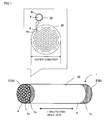
- Fig. 1 shows an embodiment of a monolithic separation membrane structure 1 of the present invention.
- the monolithic separation membrane structure 1 (hereinbelow also referred to simply as a separation membrane structure) has a monolith-shaped substrate 30 (monolithic substrate) and a separation membrane 33 (in the present specification, the substrate 30 is also referred to as a monolithic porous body 9 (or simply as a porous body 9)).
- the "monolithic substrate” in the present invention means a substrate having a shape where a plurality of cells are formed from one end face to the other end face in the longitudinal direction or a honeycomb shape.
- the separation membrane structure 1 has porous partition walls 3 having a large number of pores formed therein, and cells 4 functioning as fluid passages are formed by the partition walls 3.
- the substrate 30, the separation membrane 33, and the like will be described in detail.
- the material for the substrate 30 is porous, such as ceramics, metals, and resins. Of these, porous ceramics are preferable. It is more preferable that the aggregate particles are of alumina (Al 2 O 3 ), titania (TiO 2 ), mullite (Al 2 O 3 . SiO 2 ), Scherben, cordierite (Mg 2 Al 4 Si 5 O 18 ), or the like. Of these, alumina is furthermore preferable because a raw material (aggregate particles) having a controlled particle size can easily be obtained, a stable kneaded material can be formed, and it has high corrosion resistance.
- the substrate 30 has a round pillar external shape and an outer peripheral face 6, however the entire shape and size of the substrate 30 are not particularly limited as long as they do not inhibit the separation function.
- the entire shape there can be mentioned a round pillar (cylindrical) shape, a square pillar shape (a tubular shape having a square cross section perpendicular to the central axis), a triangular pillar shape (a tubular shape having a triangular cross section perpendicular to the central axis), and the like.
- a round pillar shape is preferable because of easy extrusion, little firing deformation, and easy sealing with the housing.
- a round pillar shape where the diameter in a cross section perpendicular to the central axis is 30 to 220 mm and the length in the central axial direction is 150 to 2000 mm.
- the substrate 30 has a plurality of cells 4 functioning as fluid passages defined and formed by porous partition walls 3 from one end face 2a to the other end face 2b in the longitudinal direction.
- the substrate 30 has 30 to 2500 cells 4 extending through to both end sides in the longitudinal direction and parallel to the longitudinal direction.
- the cross-sectional shape of the cell 4 of the substrate 30 shape in a cross section perpendicular to the extension direction of the cells 4
- a circle an ellipse, and a polygon.
- the polygon there can be mentioned a quadrangle, a pentagon, a hexagon, a triangle, and the like.
- the extension direction of the cells 4 is the same as the central axial direction in the case where the substrate 30 has a round pillar (cylindrical) shape.
- the diameter of the cell 4 is preferably 1 to 5 mm.
- the diameter of 1 mm or more enables to secure the membrane area sufficiently.
- the diameter of 5 mm or less enables the strength to be sufficient.
- an intermediate layer and a surface layer having a small average particle size and a surface layer can be laminated on the substrate 30.
- these layers are included in the porous body 9.
- sealing portions 1s are disposed on both the end faces 2, 2 of the substrate 30. Such disposition of sealing portions 1s enables to inhibit part of mixture from directly flowing into the inside of the substrate 30 from the end face 2 of the substrate 30 without passing through the separation membrane 33, thereby inhibiting the mixture from being mixed with gas or the like which has passed through the separation membrane 33 and being discharged from the outer peripheral face 6.
- the sealing portion 1s include a glass seal and a metal seal.
- the separation membrane 33 has a plurality of pores formed therein and an average pore size smaller than that of the porous body 9 (substrate 30 or including the intermediate layer and the surface layer if provided) and is disposed on the wall faces (inner wall faces 4s) inside the cells 4.
- the average pore size of the separation membrane 33 can appropriately be determined depending on the required filtration performance or separation performance (particle size of the substance to be removed). For example, in the case of a ceramic filter used for micro filtration or ultrafiltration, it is preferably 0.01 to 1.0 ⁇ m. In this case, the average pore size of the separation membrane 33 is a value measured by the air flow method described in ASTM F316.
- the separation membrane 33 there may be employed a gas separation membrane or a reverse osmosis membrane.
- the separation membrane 33 is not particularly limited, it is preferably formed of an inorganic material. More specifically, as the inorganic material, there can be mentioned zeolite, carbon, silica, and the like.
- the separation membrane 33 is a zeolite membrane
- the zeolite there may be used such a zeolite having a crystal structure including LTA, MFI, MOR, FER, FAU, DDR, CHA, and BEA.
- the separation membrane 33 is of a DDR type zeolite, it can be used particularly as a gas separation membrane used for selectively separating carbon dioxide.
- a method for separating part of components out of a fluid where plural kinds are mixed by use of a separation membrane structure 1 of the present embodiment will be described.
- the separation membrane structure 1 is housed in a tubular housing 51 having a fluid inlet port 52 and a fluid outlet port 53, so that the fluid to be treated F1 allowed to flow in from the fluid inlet port 52 of the housing 51 is separated by the separation membrane structure 1, and the separated fluid to be treated (treated fluid F2) is discharged from the fluid outlet port 53.
- the separation membrane structure 1 When the separation membrane structure 1 is housed in the housing 51, as shown in Fig. 2A , it is preferable to seal a gap between the separation membrane structure 1 and the housing 51 with the sealing members 54, 54 at both the end portions of the separation membrane structure 1.
- the sealing member 54 for example, an O-ring can be mentioned.
- the fluid to be treated F1 and the treated fluid F2 can be inhibited from being mixed together by the sealing members 54, 54.
- Fig. 2B shows another embodiment where a separation membrane structure 1 is mounted in the housing 51.
- the separation membrane structure 1 is housed in the tubular housing 51 having a fluid inlet port 52 and fluid outlet ports 53, 58.
- the fluid to be treated F1 allowed to flow in from the fluid inlet port 52 of the housing 51 can be separated by the separation membrane structure 1, the separated fluid to be treated (treated fluid F2) can be discharged from the fluid outlet port 53, and the rest (fluid F3) can be discharged from the fluid outlet port 58. Since the fluid F3 can be discharged from the fluid outlet port 58, the flow rate of the fluid to be treated F1 can be increased in operation, and the permeation flow rate of the treated fluid F2 can be increased.
- a method for manufacturing a separation membrane structure 1 of the present invention will be described.
- a raw material for a porous body is formed. It is extruded by the use of a vacuum extruder, for example. Thus an unfired monolithic substrate 30 having cells 4 is obtained. Alternatively, there are press forming, cast forming, and the like, which may appropriately be selected.
- the unfired substrate 30 is fired at 900 to 1450°C, for example. It is to be noted that an intermediate layer and a surface layer may be formed in the cells 4.
- the separation membrane 33 is formed on the inner wall faces 4s of the cells 4. Descriptions will be given with the cases of forming a zeolite membrane, a silica membrane, and a carbon membrane as the separation membrane 33 as examples.
- a zeolite membrane used in the present invention can be synthesized by a conventionally known method.
- a raw material solution (sol 67) of a silica source, an alumina source, an organic template, an alkali source, water, and the like is prepared, and, after a porous body 9 (substrate 30) and the raw material solution (sol 67) prepared are put in a pressure resistant vessel 65, these are put in a drier 68 and heated at 100 to 200°C for 1 to 240 hours to perform a heating treatment (hydrothermal synthesis), thereby forming a zeolite membrane.
- the porous body 9 (substrate 30) in advance.
- the porous body 9 having a zeolite membrane formed thereon is washed with water or warm water of 80 to 100°C and then taken out to be dried at 80 to 100°C.
- the porous body 9 is put in an electric furnace and heated at 400 to 800°C for 1 to 200 hours in an air atmosphere to burn away the organic template in the pores of the zeolite membrane.
- the zeolite membrane can be formed.
- silica source there can be mentioned colloidal silica, tetraethoxysilane, liquid glass, silicon alkoxide, fumed silica, precipitated silica, and the like.
- the organic template is used for forming the pore structure of zeolite. Though it is not particularly limited, there can be mentioned organic compounds such as tetraethylammonium hydroxide, tetraethylammonium bromide, 1-adamantanamine, tetrapropylammonium hydroxide, tetrapropylammonium bromide, and tetramethylammonium hydroxide.
- alkali metals such as sodium hydroxide, lithium hydroxide, potassium hydroxide
- alkali earth metals such as magnesium hydroxide and calcium hydroxide
- quaternary ammonium hydroxide and the like.
- the method for forming the zeolite membrane can appropriately be applied to the zeolite having a crystal structure of LTA, MFI, MOR, FER, FAU, DDR, CHA, BEA, or the like.
- a precursor solution (silica sol solution) for forming a silica membrane can be prepared by subjecting tetraethoxysilane to hydrolysis in the presence of nitric acid to obtain a sol solution, which is then diluted with ethanol. Instead of diluting with ethanol, dilution with water is also possible. Then, the precursor solution (silica sol solution) to form the silica membrane is poured from above the porous body 9 and allowed to pass through the cells 4 or subjected to general dipping to allow the precursor solution to adhere to the inner wall faces of the cells 4.
- the temperature is raised at a rate of 10 to 100°C/hour, and, after it was maintained at 350 to 600°C for 1 to 100 hours, it was lowered at a rate of 10 to 100°C/hour.
- Such operations of pouring, drying, raising temperature, and lowering temperature are repeated 3 to 10 times to form the silica membrane.
- a separation membrane structure 1 having a silica membrane as the separation membrane 33 can be obtained.
- a membrane may be formed by bringing the precursor solution for forming a carbon membrane into contact with the surface of the porous body 9 by means of dip coating, immersion, spin coating, spray coating, or the like.
- the precursor solution can be obtained by mixing and dissolving a thermosetting resin such as phenol resin, melamine resin, urea resin, furan resin, polyimide resin, and epoxy resin; a thermoplastic resin such as polyethylene; a cellulose-based resin; or a precursor substance of such a resin into an organic solvent such as methanol, acetone, tetrahydrofuran, NMP, or toluene; water; or the like.
- a thermosetting resin such as phenol resin, melamine resin, urea resin, furan resin, polyimide resin, and epoxy resin
- a thermoplastic resin such as polyethylene
- a cellulose-based resin a precursor substance of such a resin into an organic solvent such as methanol, acetone, tetrahydrofuran, NMP, or toluene
- water or the like.
- Fig. 5 shows another embodiment of a monolithic separation membrane structure 1 of the present invention.
- the present embodiment has a plurality of separation cells 4a extending through from one end face 2a to the other end face 2b formed in rows and a plurality of water collection cells 4b formed from the one end face 2a to the other end face 2b in rows.
- the separation cells 4a and the water collection cells 4b of the separation membrane structure 1 have a circular cross-sectional shape. Both the end faces 2a, 2b of the separation cells 4a are open (left open).
- the openings of both the end faces 2a, 2b are plugged with plugging members to form plugging portions 8, and discharge passages 7 are provided so that the water collection cells 4b communicate with the external space.
- the separation membrane 33 is disposed on the surfaces of the inner wall faces 4s of the separation cells 4a.
- the separation membrane structure 1 manufactured as described above may have defects in the separation membrane 33.
- the separation membrane 33 has a defect, it cannot be used as a product. Therefore, it is necessary to detect presence/absence of a defect.
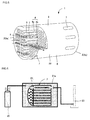
- a defect detection method will be described using Fig. 6 .
- the first defect detection method is a method where each cell 4 is pressurized with gas from outside of the cell 4, an amount of permeation of the gas permeated into each cell 4 is measured, and a cell 4 having the amount of permeation greater than "average value of all cells + A" (wherein A is a predetermined value of ⁇ to 6 ⁇ , where ⁇ is the standard deviation) is considered to be defective.
- a cell 4 to be measured is plugged with a plug 21 such as a silicon plug, and the other end of the cell 4 is connected to a flowmeter 22 such as a soap-film flowmeter 22 (the plug 21 a on the other side has a hole formed therein, and a tube is connected to the flowmeter 22).
- the plug 21 is made of resin having a conical or cone-frustum shape. The use of such a plug 21 enables to enhance airtightness.
- a gas (evaluation gas) having a larger molecular size than the pore size of the zeolite, such as CF 4 is supplied (e.g., 0.2 MPa) from the gas cylinder 23 from the outer surface of the separation membrane structure 1, and the time for a certain amount (e.g., 0.5 cc) of the evaluation gas leaked from the cell 4 is measured to calculate the permeation amount of the evaluation gas.
- the measurement is performed for all the cells 4, and the standard deviation ⁇ of the gas permeation amount of the evaluation gas is calculated from the permeation amount data of the evaluation gas for each cell 4.
- the cells 4 where the permeation amount is larger than "average value of all cells + A" are cells 4 having a large influence on the decrease of the separation coefficient. Therefore, detection of low separation coefficient cells having more defects and lower separation coefficient than the other cells 4 by the use of ⁇ to 6 ⁇ enables to selectively detect the cells 4 having a large influence on the decrease of separation coefficient. Detection and repair of the low separation coefficient cells (defective cells) in one monolithic separation membrane structure 1 enable to raise the separation coefficient of the entire monolithic separation membrane structure.
- the second defect detection method is a method where pressure is reduced for each cell 4, the degree of vacuum in each cell 4 is measured, and a cell 4 having the degree of vacuum worse than "average value of all cells + A" (wherein A is a predetermined value of ⁇ to 6 ⁇ , where ⁇ is the standard deviation) is considered to be defective.
- both the ends of a cell 4 to be measured are plugged with plugs 21 a such as silicon plugs having a hole formed therein. It is preferable that the plug 21 a is made of resin having a conical or cone-frustum shape. The use of such a plug 21 a enables to enhance airtightness.
- a vacuum pump 25 is connected to the plug 21a on one side, and a vacuum gauge 26 is connected to the plug 21 a on the other side.
- the inside of the cell 4 is subjected to vacuum drawing by a vacuum pump 25 and the achieved degree of vacuum inside the cell 4 is measured. The measurement is performed for all the cells 4, and the standard deviation ⁇ of the degree of vacuum is calculated from the data of the achieved degree of vacuum for each cell 4.
- the cells 4 with a degree of vacuum worse than "average value of all cells + A" are cells 4 having a large influence on the decrease of the separation coefficient. Therefore, detection of low separation coefficient cells having more defects and lower separation coefficient than the other cells 4 by the use of ⁇ to 6 ⁇ enables to selectively detect the cells 4 having a large influence on the decrease of separation coefficient. That is, detection and repair of the low separation coefficient cells (defective cells) in one monolithic separation membrane structure 1 enable to raise the separation coefficient of the entire monolithic separation membrane structure.
- the defect detection method of the present invention can detect low separation coefficient cells (defective cells) having particularly low separation coefficient in comparison with the other cells 4 in one monolithic separation membrane structure.
- a separation membrane structure which is considered to be defective as described above cannot be used as a product as it is. Therefore, a method for repairing defects will be described.
- the first repair method for a monolithic separation membrane structure of the present invention is a method where a polymer compound 27 having plasticity and fluidity is poured into the defective cells 4 of the monolithic separation membrane structure 1 having a separation membrane 33 formed on the inner wall faces of the cells 4 and cured to seal the defective cells.
- Fig. 8 shows a cross-sectional view of a separation membrane structure 1 repaired by pouring a polymer compound 27 as a sealing member through which a fluid does not pass into the defective cells and curing it. It is preferable that at least the both end portions of part of the cells 4 are sealed with the polymer compound 27. Furthermore, it is preferable that the polymer compound 27 is poured into each of the end portions of the cells 4 up to 1 mm or more and cured.
- All the inside of defective cells 4 may be filled with the polymer compound 27. Since this inhibits the mixture (mixed gas, mixed liquid, etc.) from entering the defective cells 4, degradation in separation performance can be inhibited. It is to be noted that the sealing with the polymer compound 27 in Fig. 8 is performed for separation cells 4a in Fig. 5 , and it is different from the plugging portions 8 in the water collection cells 4b of Fig. 5 .
- the second repair method for a monolithic separation membrane structure of the present invention is a method where the defective cells 4 are sealed by inserting a polymer compound 27 formed in advance into the defective cells 4. At that time, an adhesive may be used together.
- Fig. 9 shows a separation membrane structure where a polymer compound formed in advance is inserted in the defective cells. Also in the second method, at least the both end portions of part of cells 4 are sealed with a polymer compound 27.
- the separation membrane structure 1 where the defective cells 4 are sealed with polymer compound has no problem in use.
- synthetic resin can be mentioned. More specifically, as the synthetic resin, there can be mentioned epoxy, silicone-based, and fluorine-based synthetic resins.
- the withstand pressure for use which is the maximum pressure where no defect is caused in the repaired portion (portion sealed with a polymer compound) and the separation membrane 33 even by pressurization, and no degradation in separation performance is caused, is 1 MPa or more.
- the withstand pressure for use means the maximum pressure where no degradation in separation performance has occurred after pressurizing the cells of the separation membrane structure 1. That is, when (separation coefficient after pressurization / separation coefficient before pressurization) ⁇ 1, the separation performance is considered to be degraded, and the maximum pressure where separation performance has not occurred is the withstand pressure for use (separation performance retention strength).
- the method for repairing the cell 4 where a permeation amount or a degree of vacuum is deviated from each average value of the present invention can repair the cells 4 having more defects than the other cells 4. Targeting such cells 4 for repair enables to efficiently raise the separation coefficient of the entire monolithic separation membrane structure.
- a monolithic substrate 30 was manufactured, and a separation membrane 33 was formed inside the cells 4. First, manufacturing of the substrate 30 will be described.
- alumina particles having an average particle size of 50 ⁇ m were added 20 parts by mass of an inorganic binder (sintering auxiliary agent), water, a dispersant, and a thickener were further added, and mixed and kneaded to prepare a kneaded material.
- the kneaded material was extruded to produce an unfired monolithic substrate 30.
- the substrate 30 was fired.
- the firing conditions were 1250°C and 1 hour, and both the temperature rising rate and the temperature falling rate were 100°C/hour.
- Each of the porous bodies 9 (substrates 30) of Examples 1 to 3 and 5 to 6 had a round pillar external shape, an outer diameter of 30 mm and a full length of 160 mm and 55 cells having a cell diameter of 2.5 mm (Example 3 had 30 water collection cells 4b).
- the porous body 9 (substrate 30) of Example 4 had an outer diameter of 180 mm and a full length of 1000 mm, and 2050 cells with a cell diameter of 2.5 mm.
- a DDR membrane was formed on the inner wall faces 4s of the cells 4.
- a DDR type zeolite crystal powder was prepared based on the method for producing DDR type zeolite described in M. J. den Exter, J. C. Jansen, H. van Bekkum, Studies in Surface Science and Catalysis vol. 84, Ed. by J. Weitkamp et al., Elsevier (1994) 1159-1166 , or JP-A-2004-083375 , and the powder was used as it was or by pulverizing it if necessary as seed crystals. After the seed crystals subjected to synthesis or pulverization were dispersed in water, coarse particles were removed to prepare a seed crystal dispersion liquid.
- the seed crystal dispersion liquid prepared in (1) was diluted with ion-exchanged water or ethanol, adjusted to have a DDR concentration of 0.001 to 0.36 mass% (solid content in the slurry 64), and stirred with a stirrer at 300 rpm to obtain a seeding slurry liquid (slurry 64).
- the porous body 9 was fixedly attached to the lower end of a wide-mouth funnel 62, and 160ml of the seeding slurry liquid was poured from above the porous body 9 and allowed to pass through the cells 4 (see Fig. 3 ).
- the porous body 9 where the slurry 64 flowed down was dried by sending wind in the cells for 10 to 30 minutes under the conditions of room temperature or 80°C and a wind velocity of 3 to 6 m/s. Flowing down of the slurry 64 and drying by sending wind were repeated one to six times to obtain a sample. After drying, microstructure observation was performed with an electron microscope. Adhesion of DDR particles to the surface of the porous body 9 was confirmed.
- the porous body 9 where DDR particles were allowed to adhere thereto in the above (2) was disposed in the stainless steel pressure resistant vessel 65 having a fluorine resin inner cylinder having an inner volume of 300 ml, and the prepared raw material solution (sol 67) was put in and subjected to a heating treatment (hydrothermal synthesis) at 140°C for 50 hours (see Fig. 4 ).
- the membrane formed was heated at 450 or 500°C for 50 hours in an air atmosphere in an electric furnace to burn away 1-adamantanamine in the pores.
- the crystal phase was identified by X-ray diffraction and was confirmed to be DDR type zeolite. After forming the membrane, it was confirmed that the porous body 9 was coated with DDR type zeolite.
- a silica membrane was formed on the inner wall faces 4s.
- the precursor solution (silica sol solution) to form a silica membrane was prepared by subjecting tetraethoxysilane to hydrolysis in the presence of nitric acid to obtain a sol solution and diluting it with ethanol.
- the precursor solution (silica sol solution) to form the silica membrane was poured into the porous body 9 having the inner wall faces 4s formed therein from above and allowed to flow through the cells 4 to allow the precursor solution to adhere to the inner wall faces of the cells 4. Then, after temperature was raised at a rate of 100°C/hour and maintained at 500°C for one hour, the temperature was lowered at a rate of 100°C/hour.
- Such operations of pouring, drying, raising temperature, and lowering temperature were repeated 3 to 5 times to form a silica membrane.
- a carbon membrane was formed on the inner wall faces 4s of the cells 4.
- the precursor solution was obtained by mixing and dissolving in an organic solvent of a phenol resin.
- the precursor solution to form a carbon membrane was brought into contact with the surface of the porous body 9 to form a membrane.
- a thermal treatment at 300°C for one hour was performed to dispose a polyimide resin as the precursor of the carbon membrane on the surface.
- the obtained polyimide resin layer-provided substrate was subjected to a thermal treatment at 600°C for five hours in a non-oxidizing atmosphere to obtain the carbon membrane.
- Defects of the separation membrane structure 1 having a separation membrane 33 formed therein was detected by using a method of measuring the degree of vacuum or a method of measuring the gas permeation amount.
- the degree of vacuum of each cell 4 was measured. Suction was performed on one side of the cells 4 by a vacuum pump (Model No. G-20DA produced by AS One Corporation, exhaust velocity of 24 L/min., ultimate pressure of 1.3 ⁇ 10 -1 Pa, two stage type), and a vacuum gauge (calibrator Model No. DP1800 produced by GE Sensing) is connected to the cells 4 on the other side so that the inside of the cells was vacuumed and the achieved degree of degree of vacuum inside the cell 4 was measured.
- a vacuum pump Model No. G-20DA produced by AS One Corporation, exhaust velocity of 24 L/min., ultimate pressure of 1.3 ⁇ 10 -1 Pa, two stage type
- a vacuum gauge calibrator Model No. DP1800 produced by GE Sensing
- Example 1 The average value of all the cells 4 and the standard deviation ( ⁇ ) were calculated, and a cell with the degree of vacuum worse than "average value + 2 ⁇ " (low-vacuum cell) was considered as a cell having a defect generated therein (more defects than the other cells 4).
- the results of Example 1 are shown in table 1.
- the cell numbers are as shown in Fig. 10A , and all the 55 cells 4 were checked for the degree of vacuum. Incidentally, the degrees of vacuum in the table are shown by gauge pressure (minus expression on the basis of air atmosphere).
- the average value of the degrees of vacuum of 55 cells 4 was -99.76 kPa, the standard deviation ( ⁇ ) was 0.15 kPa, and the "average value + 2 ⁇ " was -99.46 kPa. Therefore, the three cells 4 having cell numbers 1, 16, and 43 were considered to be defective.
- gas having a molecular size not smaller than the pore size of the membrane was introduced into the cells 4, and defects were checked from the gas permeation amount.
- tetrafluoromethane was used. First, one end of a cell 4 to be measured was plugged with a silicon plug, and, after the other end of the cell 4 was connected to a soap-film flowmeter, tetrafluoromethane was supplied at 0.2 MPa from the external surface of the monolithic substrate. The time that elapsed before 0.5 cc of the tetrafluoromethane leaked out of the cell was measured to calculate the permeation amount of the tetrafluoromethane. In the case of a silica membrane or a carbon membrane, sulfur hexafluoride was used.
- Example 3 The average value of the permeation amount and the standard deviation ( ⁇ ) of all the cells 4 were calculated, and the cell having a permeation amount greater than "average value + 2 ⁇ " was considered as a cell having a defect generated therein (more defects than the other cells 4).
- the results of Example 3 are shown in Table 2.
- the cell numbers were as shown in Fig. 10B , and all the 30 cells 4 were checked for the degree of vacuum. [Table 2] Cell No. Tetrafluoromethane permeation amount (L/m 2 ⁇ s ⁇ MPa) Cell No.
- Tetrafluoromethane permeation amount (L/m 2 ⁇ s ⁇ MPa) 1 0.0001 16 0.0012 2 0.0009 17 0.0005 3 0.0009 18 0.0008 4 0.0010 19 0.0004 5 0.0003 20 0.0011 6 0.0001 21 0.0009 7 0.0023 22 0.0008 8 0.0001 23 0.0008 9 0.0013 24 0.0005 10 0.0023 25 0.0010 11 0.0011 26 0.0009 12 0.0011 27 0.0008 13 0.0002 28 0.0009 14 0.0015 29 0.0024 15 0.0005 30 0.0020 L/m 2 ⁇ s ⁇ MPa Average value 0.0009 ⁇ 0.0006 Average value+2 ⁇ 0.0021
- the average value of the permeation amounts of 30 cells 4 was 0.0009 L/m 2 ⁇ s ⁇ MPa, the standard deviation ( ⁇ was 0.0006 L/m 2 ⁇ s ⁇ MPa, and the "average value + 2 ⁇ " was 0.0021 L/m 2 ⁇ s ⁇ MPa. Therefore, the three cells 4 having cell numbers of 7, 10, and 29 were considered to be defective.
- Examples 2 and 4 to 7 other than Example 1 (Table 1) and Example 3 (Table 2), defects were detected in the same manner, and the cells 4 considered to be defective were repaired.
- An epoxy resin (E200 produced by Konishi Co., Ltd.) was poured into the three defective cells detected from the measurement of degree of vacuum of the separation membrane structure 1 up to 5 mm from one end face and dried at room temperature for 24 hours to seal the cells 4.
- Silicon plugs (Model 2 pink produced by AS ONE Corporation) formed into a conical shape in advance were inserted into the four defective cells detected from the measurement of degree of vacuum of the separation membrane structure 1 and fixed to seal the cells 4.
- Perfluor plugs produced by AIR WATER MACH INC. formed into a conical shape in advance were inserted into the three defective cells detected from the measurement of gas permeation amount and fixed to seal the cells 4.
- Example 4 used a large-sized porous body 9 having an outer diameter of 180 mm, an entire length of 1000 mm, and 2050 cells having a cell diameter of 2.5 mm.
- An epoxy resin (E200 produced by Konishi Co., Ltd.) was poured into the 31 defective cells detected from the measurement of degree of vacuum of the separation membrane structure 1 up to 10 mm from an end face and dried at room temperature for 24 hours to seal the cells 4.
- Silicon plugs (Model 2 pink produced by AS ONE Corporation) formed into a conical shape in advance were inserted into the nine defective cells detected from the measurement of gas permeation amount of the separation membrane structure 1 and fixed to seal the cells 4.
- Perfluor plugs produced by AIR WATER MACH INC. formed into a conical shape in advance were inserted into the seven defective cells detected from the measurement of degree of vacuum and fixed to seal the cells 4.
- Silicon plugs (Model 2 pink produced by AS ONE Corporation) formed into a conical shape in advance were inserted into the three defective cells detected from the measurement of degree of vacuum of the separation membrane structure 1 and fixed to seal the cells 4.
- the separation coefficients before the repair and after the repair were obtained as follows.
- a mixed gas of carbon dioxide (CO 2 ) and methane (CH 4 ) (the volume ratio of carbon dioxide (CO 2 ) to methane (CH 4 ) was 50:50, and the partial pressure of each gas was 0.2 MPa) was introduced into the cells 4 of the separation membrane structure 1.
- the repaired separation membrane 1 was housed in a cylindrical housing 51 having a fluid inlet 52 and a fluid outlet 53, and, after water was allowed to flow into the housing from the fluid inflow port 52 of the housing 51 to apply pressure of 5 MPa with water, drying was performed with a drier. Then, the separation coefficient was calculated in the same manner as described above.
- the separation coefficient has increased after the repair in comparison with that before the repair, and the effect of repair was confirmed.
- the separation performance after pressurization at 5 MPa with water of the separation membrane structure 1 after repair no decrease in the separation coefficient by the pressurization has been recognized. That is, it can be said that the withstand pressure for use (separation performance retention strength) was 5 MPa or more, and pressure resistance of the repaired portion was confirmed.
- the separation membrane structure 1 sealed with a polymer compound could withstand 5 MPa or more.
- no problem due to pressurization at 5 MPa with water has caused regarding the gas permeation amount, too.
- the defect detection method and the repair method of the present invention can be used for detection and repair of defects in a monolithic separation membrane structure having a separation membrane formed on the inner wall faces of the cells.
- the monolithic separation membrane structure of the present invention can be used for separation for a mixed gas or a mixed liquid.
Landscapes
- Chemical & Material Sciences (AREA)
- Chemical Kinetics & Catalysis (AREA)
- Inorganic Chemistry (AREA)
- General Physics & Mathematics (AREA)
- Physics & Mathematics (AREA)
- Life Sciences & Earth Sciences (AREA)
- Engineering & Computer Science (AREA)
- Mechanical Engineering (AREA)
- Geology (AREA)
- Dispersion Chemistry (AREA)
- General Health & Medical Sciences (AREA)
- Immunology (AREA)
- Pathology (AREA)
- Biochemistry (AREA)
- Analytical Chemistry (AREA)
- Health & Medical Sciences (AREA)
- Separation Using Semi-Permeable Membranes (AREA)
- Porous Artificial Stone Or Porous Ceramic Products (AREA)
- Silicon Compounds (AREA)
- Silicates, Zeolites, And Molecular Sieves (AREA)
- Carbon And Carbon Compounds (AREA)
Abstract
Description
- The present invention relates to a defect detection method for monolithic separation membrane structures in which a separation membrane is formed on the inner wall faces of the cells thereof, a repair method, and monolithic separation membrane structures.
- Recently, ceramic filters have been used in order to selectively collect only a specific component from a multicomponent mixture (mixed fluid). Since a ceramic filter is superior to an organic polymer filter in mechanical strength, durability, corrosion resistance, and the like, it is preferably used for removing suspended matter, bacteria, powder dust, etc., in a liquid or gas in wide fields such as water treatment, exhaust gas treatment, medication, and food fields.
- In such a ceramic filter, it is necessary to increase the membrane area (area of the separation membrane) in order to improve water permeability while securing separation performance, and, to do so, it is desirable that the filter has a honeycomb shape (monolithic shape). In many cases, the monolithic separation membrane structure means a structure having a round pillar external shape and being provided with a porous substrate having a large number of parallel passages (cells) formed in the axial direction thereof wherein separation membrane having a hole diameter smaller than that of the porous substrate is formed on the inner wall faces forming the cell.
- In the case of forming a separation membrane on the monolithic substrate
- (honeycomb structure), part of the cells having a defect influences the quality of products even if a good membrane is formed on many cells. The
Patent Document 1 discloses a defect inspection method and a defect repair method for a ceramic membrane. - [Patent Document 1]
JP-A-H8-131786 - However, the defect inspection method and the defect repair method of the
Patent Document 1 is a method of inspecting defects on the outer face of the tube and repairing them. - The detection of defects caused inside a cell of a monolithic substrate is not possible by visual inspection. In addition, there has been no simple repair method for defects occurred inside the cells of the monolithic substrate.
- An objective of the present invention is to provide a simple defect detection method for detecting a defect of a monolithic separation membrane structure in which a separation membrane is formed on the cells. In addition, there is provided a monolithic separation membrane structure repair method for repairing a monolithic separation membrane structure having a defective cell. Furthermore, there is provided a monolithic separation membrane structure where the defect is repaired.
- In order to solve the aforementioned problems, according to the present invention, there are provided the following defect detection method for monolithic separation membrane structures, repair method, and monolithic separation membrane structures.
- [1] A monolithic separation membrane structure comprising: a monolithic substrate having a plurality of cells defined and formed by porous partition walls from one end face to the other end face in the longitudinal direction, and a separation membrane formed on inner wall faces of the cells;
wherein at least both end portions of part of the cells are sealed with sealing members through which fluid does not pass. - [2] The monolithic separation membrane structure according to [1], wherein the sealing members are of polymer compound.
- [3] The monolithic separation membrane structure according to [2], wherein the polymer compound is a synthetic resin.
- [4] The monolithic separation membrane structure according to [3], wherein the synthetic resin is one of epoxy, silicon-based, and fluorine-based resins.
- [5] The monolithic separation membrane structure according to any one of [1] to [4], wherein the separation membrane is formed of an inorganic material.
- [6] The monolithic separation membrane structure according to [5], wherein the inorganic material is one of zeolite, carbon, and silica.
- [7] The monolithic separation membrane structure according to any one of [1] to [6], wherein the monolithic substrate is of a porous ceramic.
- [8] The monolithic separation membrane structure according to any one of [1] to [7], wherein the withstand pressure for use is 1 MPa or more.
- [9] A repair method for a monolithic separation membrane structure, wherein at least both end portions of at least part of cells among defective cells of the monolithic separation membrane structure in which a separation membrane is formed on inner wall faces of cells of a monolithic substrate having a plurality of cells defined and formed by porous partition walls from one end face to the other end face in the longitudinal direction are sealed with sealing members through which fluid does not pass.
- [10] The repair method for a monolithic separation membrane structure according to [9], wherein a polymer compound as the sealing member is poured into the defective cells of the monolithic separation membrane structure and cured to seal the defective cells.
- [11] The repair method for a monolithic separation membrane structure according to [9], wherein a polymer compound formed in advance as the sealing member is inserted into the defective cells of the monolithic separation membrane structure to seal the defective cells.
- [12] A defect detection method for a monolithic separation membrane structure in which a separation membrane is formed on inner wall faces of cells of a monolithic substrate having a plurality of cells defined and formed by porous partition walls from one end face to the other end face in the longitudinal direction, wherein each cell is pressurized with gas from outside of the cell, an amount of permeation of the gas permeated into each cell is measured, and a cell having the amount of permeation greater than "average value of all cells + A" (wherein A is a predetermined value of σ to 6σ, where σ is the standard deviation) is considered to be defective.
- [13] A defect detection method for a monolithic separation membrane structure in which a separation membrane is formed on inner wall faces of cells of a monolithic substrate having a plurality of cells defined and formed by porous partition walls from one end face to the other end face in the longitudinal direction, wherein pressure is reduced for each cell, a degree of vacuum in each cell is measured, and a cell having the degree of vacuum worse than "average value of all cells + A" (wherein A is a predetermined value of σ to 6σ, where σ is the standard deviation) is considered to be defective.
- The defect detection method for monolithic separation membrane structure of the present invention has no oversight because the defects are detected as a numerical value. Since the repair method for monolithic separation membrane structure of the present invention is not a method where the defects are directly repaired, but a method where a cell itself is filled, it enables to repair easily in a short period of time. In particular, the separation coefficient of the entire monolithic separation membrane structure can be enhanced by detecting the cells having a larger amount of defects in comparison with the other cells and repairing the cells. Repairing only the cell(s) having defects improves the product yield.
-
- [
Fig. 1] Fig. 1 is a view showing an embodiment of a monolithic separation membrane structure of the present invention. - [
Fig. 2A] Fig. 2A is a schematic view showing an embodiment where a monolithic separation membrane structure is mounted in the housing and showing a cross section parallel to the direction which the cells of the ceramic separation membrane structure extend. - [
Fig. 2B] Fig. 2B is a schematic view showing another embodiment where a monolithic separation membrane structure is mounted in the housing and showing a cross section parallel to the direction which the cells of the ceramic separation membrane structure extend. - [
Fig. 3] Fig. 3 is a schematic view showing a state where seeding slurry is poured in a particle adhesion step. - [
Fig. 4] Fig. 4 is a schematic view showing an embodiment of a membrane formation step, where a zeolite membrane is formed on a porous body by hydrothermal synthesis. - [
Fig. 5] Fig. 5 is a perspective view showing another embodiment of a monolithic separation membrane structure of the present invention. - [
Fig. 6] Fig. 6 is a view for illustrating measurement of gas permeation amount. - [
Fig. 7] Fig. 7 is a view for illustrating measurement of degree of vacuum. - [
Fig. 8] Fig. 8 is a cross-sectional view of a separation membrane structure repaired by pouring a polymer compound into defective cells. - [
Fig. 9] Fig. 9 is a view showing a separation membrane structure where defective cells are sealed by inserting polymer compounds formed in advance into defective cells. - [
Fig. 10A] Fig. 10A is a view showing cell numbers of the cells of a monolithic separation membrane structure. - [
Fig. 10B] Fig. 10B is a view showing cell numbers of the cells of a monolithic separation membrane structure of another embodiment. - Hereinbelow, embodiments of the present invention will be described with referring to drawings. The present invention is not limited to the following embodiments, and changes, modifications, and improvements may be added as long as they do not deviate from the scope of the invention.
- A defect detection method for monolithic separation membrane structures of the present invention is a defect detection method for a monolithic separation membrane structure in which a separation membrane is formed on the inner wall faces of the cells of the monolithic substrate having a plurality of cells defined and formed by porous partition walls from one end face to the other end face in the longitudinal direction. Each cell is pressurized with gas from outside of the cell, the amount of permeation of the gas permeated into each cell is measured, and a cell having a permeation amount greater than "average value of all cells + A" (wherein A is a predetermined value of σ to 6σ, where σ is the standard deviation) is considered to be defective. That is, such a cell is considered as a cell having more defects than the other cells (defective cell) and an objective to be repaired.
- Alternatively, pressure is reduced for each cell, the degree of vacuum in the cell is measured, and a cell with a degree of vacuum value worse than "average value of all cells + A" (wherein A is a predetermined value of σ to 6σ, where σ is the standard deviation) is considered to be defective. That is, such a cell is considered as a cell (defective cell) having more defects than the other cells and an object of repair.
- Though the value of A may be determined within the range of σ to 6σ, σ to 5σ is preferable, and σ to 3σ is preferable when separation accuracy is required. The preferable values are 2σ in a field where a relatively high separation performance is required, such as gas separation or anhydration in a product-manufacturing step, and 5σ in a field where the costs of the separation membrane structures are given more weight to than separation accuracy, such as effluent treatment or exhaust gas collection.
- The defect detection of cells may be performed in either of permeation amount measurement and degree of vacuum measurement. It is to be noted that the standard deviation σ is obtained by the following formula, where x is a gas permeation amount (or degree of vacuum) of each cell, and n is the number of cells where the gas permeation amount (or degree of vacuum) is measured.

- The repair method for monolithic separation membrane structures of the present invention is a repair method of a monolithic substrate having a plurality of cells defined and formed by porous partition walls from one end face to the other end face in the longitudinal direction. The monolithic separation membrane structure having defects is repaired by sealing at least the both end portions of at least part of the cells having defects of the monolithic separation membrane structure with sealing members through which fluid does not pass. Specifically, a polymer compound as the sealing member is poured into the defective cells of the monolithic separation membrane structure having a separation membrane formed on the inner wall faces of the cells and cured to seal the defective cell. Alternatively, a polymer compound formed in advance as the sealing member is inserted into the defective cell to seal the defective cell. It is to be noted that it is preferable to seal all the defective cells in the case where a high separation performance of the product is required.
- A monolithic separation membrane structure repaired by a repair method for monolithic separation membrane structures of the present invention includes a monolithic substrate having a plurality of cells defined and formed by porous partition walls from one end face to the other end face in the longitudinal direction and a separation membrane formed on the inner wall faces of the cells, where at least the both end portions of part of the cells are sealed with sealing members through which fluid does not passes.
- Hereinbelow, more specific descriptions will be given. A monolithic separation membrane structure will firstly be described, and then a defect detection method and a repair method for the monolithic separation membrane structure will be described.
-
Fig. 1 shows an embodiment of a monolithicseparation membrane structure 1 of the present invention. The monolithic separation membrane structure 1 (hereinbelow also referred to simply as a separation membrane structure) has a monolith-shaped substrate 30 (monolithic substrate) and a separation membrane 33 (in the present specification, thesubstrate 30 is also referred to as a monolithic porous body 9 (or simply as a porous body 9)). The "monolithic substrate" in the present invention means a substrate having a shape where a plurality of cells are formed from one end face to the other end face in the longitudinal direction or a honeycomb shape. - The
separation membrane structure 1 hasporous partition walls 3 having a large number of pores formed therein, andcells 4 functioning as fluid passages are formed by thepartition walls 3. Hereinbelow, thesubstrate 30, theseparation membrane 33, and the like will be described in detail. - There is no limitation on the material for the
substrate 30 as long as it is porous, such as ceramics, metals, and resins. Of these, porous ceramics are preferable. It is more preferable that the aggregate particles are of alumina (Al2O3), titania (TiO2), mullite (Al2O3. SiO2), Scherben, cordierite (Mg2Al4Si5O18), or the like. Of these, alumina is furthermore preferable because a raw material (aggregate particles) having a controlled particle size can easily be obtained, a stable kneaded material can be formed, and it has high corrosion resistance. - The
substrate 30 has a round pillar external shape and an outerperipheral face 6, however the entire shape and size of thesubstrate 30 are not particularly limited as long as they do not inhibit the separation function. As examples of the entire shape, there can be mentioned a round pillar (cylindrical) shape, a square pillar shape (a tubular shape having a square cross section perpendicular to the central axis), a triangular pillar shape (a tubular shape having a triangular cross section perpendicular to the central axis), and the like. Of these, a round pillar shape is preferable because of easy extrusion, little firing deformation, and easy sealing with the housing. In the case of being used for micro filtration or ultrafiltration, preferred is a round pillar shape where the diameter in a cross section perpendicular to the central axis is 30 to 220 mm and the length in the central axial direction is 150 to 2000 mm. - The
substrate 30 has a plurality ofcells 4 functioning as fluid passages defined and formed byporous partition walls 3 from oneend face 2a to theother end face 2b in the longitudinal direction. Thesubstrate 30 has 30 to 2500cells 4 extending through to both end sides in the longitudinal direction and parallel to the longitudinal direction. - As the cross-sectional shape of the
cell 4 of the substrate 30 (shape in a cross section perpendicular to the extension direction of the cells 4), there can be mentioned, for example, a circle, an ellipse, and a polygon. As the polygon, there can be mentioned a quadrangle, a pentagon, a hexagon, a triangle, and the like. It is to be noted that the extension direction of thecells 4 is the same as the central axial direction in the case where thesubstrate 30 has a round pillar (cylindrical) shape. - In the case where the cross-sectional shape of the
cell 4 of thesubstrate 30 is circular, the diameter of thecell 4 is preferably 1 to 5 mm. The diameter of 1 mm or more enables to secure the membrane area sufficiently. The diameter of 5 mm or less enables the strength to be sufficient. - It is also possible to provide a plurality of layer where the average particle size is changed on the
substrate 30. Specifically, an intermediate layer and a surface layer having a small average particle size and a surface layer can be laminated on thesubstrate 30. In the case of providing the intermediate layer and the surface layer, these layers are included in theporous body 9. - It is preferable that sealing
portions 1s are disposed on both the end faces 2, 2 of thesubstrate 30. Such disposition of sealingportions 1s enables to inhibit part of mixture from directly flowing into the inside of thesubstrate 30 from theend face 2 of thesubstrate 30 without passing through theseparation membrane 33, thereby inhibiting the mixture from being mixed with gas or the like which has passed through theseparation membrane 33 and being discharged from the outerperipheral face 6. Examples of the sealingportion 1s include a glass seal and a metal seal. - The
separation membrane 33 has a plurality of pores formed therein and an average pore size smaller than that of the porous body 9 (substrate 30 or including the intermediate layer and the surface layer if provided) and is disposed on the wall faces (inner wall faces 4s) inside thecells 4. - The average pore size of the
separation membrane 33 can appropriately be determined depending on the required filtration performance or separation performance (particle size of the substance to be removed). For example, in the case of a ceramic filter used for micro filtration or ultrafiltration, it is preferably 0.01 to 1.0 µm. In this case, the average pore size of theseparation membrane 33 is a value measured by the air flow method described in ASTM F316. - As the
separation membrane 33, there may be employed a gas separation membrane or a reverse osmosis membrane. Though theseparation membrane 33 is not particularly limited, it is preferably formed of an inorganic material. More specifically, as the inorganic material, there can be mentioned zeolite, carbon, silica, and the like. - In the case where the
separation membrane 33 is a zeolite membrane, as the zeolite, there may be used such a zeolite having a crystal structure including LTA, MFI, MOR, FER, FAU, DDR, CHA, and BEA. In the case where theseparation membrane 33 is of a DDR type zeolite, it can be used particularly as a gas separation membrane used for selectively separating carbon dioxide. - Next, a method for separating part of components out of a fluid where plural kinds are mixed by use of a
separation membrane structure 1 of the present embodiment will be described. As shown inFig. 2A , upon separation of a fluid using aseparation membrane structure 1 of the present embodiment, it is preferable that theseparation membrane structure 1 is housed in atubular housing 51 having afluid inlet port 52 and afluid outlet port 53, so that the fluid to be treated F1 allowed to flow in from thefluid inlet port 52 of thehousing 51 is separated by theseparation membrane structure 1, and the separated fluid to be treated (treated fluid F2) is discharged from thefluid outlet port 53. - When the
separation membrane structure 1 is housed in thehousing 51, as shown inFig. 2A , it is preferable to seal a gap between theseparation membrane structure 1 and thehousing 51 with the sealingmembers separation membrane structure 1. Though there is no particular limitation on the sealingmember 54, for example, an O-ring can be mentioned. - All the fluid to be treated F1 which flows into the
housing 51 from thefluid inlet port 52 enters thecells 4 of theseparation membrane structure 1, and the fluid to be treated F1 which have flown into thecells 4 passes through theseparation membrane 33 and penetrates into thesubstrate 30 as the treated fluid F2. Then, it flows out from the outerperipheral face 6 of thesubstrate 30 to the outside of thesubstrate 30 and is discharged to the outside (external space) from thefluid outlet port 53. The fluid to be treated F1 and the treated fluid F2 can be inhibited from being mixed together by the sealingmembers -
Fig. 2B shows another embodiment where aseparation membrane structure 1 is mounted in thehousing 51. As shown inFig. 2B , theseparation membrane structure 1 is housed in thetubular housing 51 having afluid inlet port 52 andfluid outlet ports fluid inlet port 52 of thehousing 51 can be separated by theseparation membrane structure 1, the separated fluid to be treated (treated fluid F2) can be discharged from thefluid outlet port 53, and the rest (fluid F3) can be discharged from thefluid outlet port 58. Since the fluid F3 can be discharged from thefluid outlet port 58, the flow rate of the fluid to be treated F1 can be increased in operation, and the permeation flow rate of the treated fluid F2 can be increased. - Next, a method for manufacturing a
separation membrane structure 1 of the present invention will be described. First, a raw material for a porous body is formed. It is extruded by the use of a vacuum extruder, for example. Thus an unfiredmonolithic substrate 30 havingcells 4 is obtained. Alternatively, there are press forming, cast forming, and the like, which may appropriately be selected. Next, theunfired substrate 30 is fired at 900 to 1450°C, for example. It is to be noted that an intermediate layer and a surface layer may be formed in thecells 4. - Next, the
separation membrane 33 is formed on the inner wall faces 4s of thecells 4. Descriptions will be given with the cases of forming a zeolite membrane, a silica membrane, and a carbon membrane as theseparation membrane 33 as examples. - Descriptions will be given on the case where a zeolite membrane is disposed as the
separation membrane 33. A zeolite membrane used in the present invention can be synthesized by a conventionally known method. For example, as shown inFig. 4 , a raw material solution (sol 67) of a silica source, an alumina source, an organic template, an alkali source, water, and the like is prepared, and, after a porous body 9 (substrate 30) and the raw material solution (sol 67) prepared are put in a pressureresistant vessel 65, these are put in a drier 68 and heated at 100 to 200°C for 1 to 240 hours to perform a heating treatment (hydrothermal synthesis), thereby forming a zeolite membrane. - At this time, it is preferable to apply zeolite as seed crystals onto the porous body 9 (substrate 30) in advance. Next, the
porous body 9 having a zeolite membrane formed thereon is washed with water or warm water of 80 to 100°C and then taken out to be dried at 80 to 100°C. Then, theporous body 9 is put in an electric furnace and heated at 400 to 800°C for 1 to 200 hours in an air atmosphere to burn away the organic template in the pores of the zeolite membrane. Thus, the zeolite membrane can be formed. - As the silica source, there can be mentioned colloidal silica, tetraethoxysilane, liquid glass, silicon alkoxide, fumed silica, precipitated silica, and the like.
- The organic template is used for forming the pore structure of zeolite. Though it is not particularly limited, there can be mentioned organic compounds such as tetraethylammonium hydroxide, tetraethylammonium bromide, 1-adamantanamine, tetrapropylammonium hydroxide, tetrapropylammonium bromide, and tetramethylammonium hydroxide.
- As the alkali source, there can be mentioned alkali metals such as sodium hydroxide, lithium hydroxide, potassium hydroxide; alkali earth metals such as magnesium hydroxide and calcium hydroxide; quaternary ammonium hydroxide: and the like.
- The method for forming the zeolite membrane can appropriately be applied to the zeolite having a crystal structure of LTA, MFI, MOR, FER, FAU, DDR, CHA, BEA, or the like.
- Descriptions will be given on the case where a silica membrane is disposed as a sealing
member 33 on the inner wall faces 4s of thecells 4. A precursor solution (silica sol solution) for forming a silica membrane can be prepared by subjecting tetraethoxysilane to hydrolysis in the presence of nitric acid to obtain a sol solution, which is then diluted with ethanol. Instead of diluting with ethanol, dilution with water is also possible. Then, the precursor solution (silica sol solution) to form the silica membrane is poured from above theporous body 9 and allowed to pass through thecells 4 or subjected to general dipping to allow the precursor solution to adhere to the inner wall faces of thecells 4. Then, the temperature is raised at a rate of 10 to 100°C/hour, and, after it was maintained at 350 to 600°C for 1 to 100 hours, it was lowered at a rate of 10 to 100°C/hour. Such operations of pouring, drying, raising temperature, and lowering temperature are repeated 3 to 10 times to form the silica membrane. Thus, aseparation membrane structure 1 having a silica membrane as theseparation membrane 33 can be obtained. - Descriptions will be given on the case of disposing a carbon membrane as a
separation membrane 33 on the inner wall faces 4s of thecells 4. In this case, a membrane may be formed by bringing the precursor solution for forming a carbon membrane into contact with the surface of theporous body 9 by means of dip coating, immersion, spin coating, spray coating, or the like. The precursor solution can be obtained by mixing and dissolving a thermosetting resin such as phenol resin, melamine resin, urea resin, furan resin, polyimide resin, and epoxy resin; a thermoplastic resin such as polyethylene; a cellulose-based resin; or a precursor substance of such a resin into an organic solvent such as methanol, acetone, tetrahydrofuran, NMP, or toluene; water; or the like. Upon forming the precursor solution into a membrane, an appropriate heating treatment may be performed according to the kind of the resin contained in the solution. Thus obtained precursor membrane is carbonated to obtain a carbon membrane. -
Fig. 5 shows another embodiment of a monolithicseparation membrane structure 1 of the present invention. The present embodiment has a plurality ofseparation cells 4a extending through from oneend face 2a to theother end face 2b formed in rows and a plurality ofwater collection cells 4b formed from the oneend face 2a to theother end face 2b in rows. Theseparation cells 4a and thewater collection cells 4b of theseparation membrane structure 1 have a circular cross-sectional shape. Both the end faces 2a, 2b of theseparation cells 4a are open (left open). In thewater collection cells 4b, the openings of both the end faces 2a, 2b are plugged with plugging members to form pluggingportions 8, and dischargepassages 7 are provided so that thewater collection cells 4b communicate with the external space. In addition, theseparation membrane 33 is disposed on the surfaces of the inner wall faces 4s of theseparation cells 4a. - The
separation membrane structure 1 manufactured as described above may have defects in theseparation membrane 33. When theseparation membrane 33 has a defect, it cannot be used as a product. Therefore, it is necessary to detect presence/absence of a defect. First, a defect detection method will be described usingFig. 6 . The first defect detection method is a method where eachcell 4 is pressurized with gas from outside of thecell 4, an amount of permeation of the gas permeated into eachcell 4 is measured, and acell 4 having the amount of permeation greater than "average value of all cells + A" (wherein A is a predetermined value of σ to 6σ, where σ is the standard deviation) is considered to be defective. - As shown in
Fig. 6 , one end of acell 4 to be measured is plugged with aplug 21 such as a silicon plug, and the other end of thecell 4 is connected to aflowmeter 22 such as a soap-film flowmeter 22 (theplug 21 a on the other side has a hole formed therein, and a tube is connected to the flowmeter 22). It is preferable that theplug 21 is made of resin having a conical or cone-frustum shape. The use of such aplug 21 enables to enhance airtightness. Then, a gas (evaluation gas) having a larger molecular size than the pore size of the zeolite, such as CF4, is supplied (e.g., 0.2 MPa) from thegas cylinder 23 from the outer surface of theseparation membrane structure 1, and the time for a certain amount (e.g., 0.5 cc) of the evaluation gas leaked from thecell 4 is measured to calculate the permeation amount of the evaluation gas. The measurement is performed for all thecells 4, and the standard deviation σ of the gas permeation amount of the evaluation gas is calculated from the permeation amount data of the evaluation gas for eachcell 4. - The
cells 4 where the permeation amount is larger than "average value of all cells + A" arecells 4 having a large influence on the decrease of the separation coefficient. Therefore, detection of low separation coefficient cells having more defects and lower separation coefficient than theother cells 4 by the use of σ to 6σ enables to selectively detect thecells 4 having a large influence on the decrease of separation coefficient. Detection and repair of the low separation coefficient cells (defective cells) in one monolithicseparation membrane structure 1 enable to raise the separation coefficient of the entire monolithic separation membrane structure. - Next, the second defect detection method will be described. The second defect detection method is a method where pressure is reduced for each
cell 4, the degree of vacuum in eachcell 4 is measured, and acell 4 having the degree of vacuum worse than "average value of all cells + A" (wherein A is a predetermined value of σ to 6σ, where σ is the standard deviation) is considered to be defective. - As shown in
Fig. 7 , both the ends of acell 4 to be measured are plugged withplugs 21 a such as silicon plugs having a hole formed therein. It is preferable that theplug 21 a is made of resin having a conical or cone-frustum shape. The use of such aplug 21 a enables to enhance airtightness. Avacuum pump 25 is connected to theplug 21a on one side, and avacuum gauge 26 is connected to theplug 21 a on the other side. The inside of thecell 4 is subjected to vacuum drawing by avacuum pump 25 and the achieved degree of vacuum inside thecell 4 is measured. The measurement is performed for all thecells 4, and the standard deviation σ of the degree of vacuum is calculated from the data of the achieved degree of vacuum for eachcell 4. - The
cells 4 with a degree of vacuum worse than "average value of all cells + A" arecells 4 having a large influence on the decrease of the separation coefficient. Therefore, detection of low separation coefficient cells having more defects and lower separation coefficient than theother cells 4 by the use of σ to 6σ enables to selectively detect thecells 4 having a large influence on the decrease of separation coefficient. That is, detection and repair of the low separation coefficient cells (defective cells) in one monolithicseparation membrane structure 1 enable to raise the separation coefficient of the entire monolithic separation membrane structure. - It is to be noted that the defect detection method of the present invention can detect low separation coefficient cells (defective cells) having particularly low separation coefficient in comparison with the
other cells 4 in one monolithic separation membrane structure. - A separation membrane structure which is considered to be defective as described above cannot be used as a product as it is. Therefore, a method for repairing defects will be described.
- The first repair method for a monolithic separation membrane structure of the present invention is a method where a
polymer compound 27 having plasticity and fluidity is poured into thedefective cells 4 of the monolithicseparation membrane structure 1 having aseparation membrane 33 formed on the inner wall faces of thecells 4 and cured to seal the defective cells.Fig. 8 shows a cross-sectional view of aseparation membrane structure 1 repaired by pouring apolymer compound 27 as a sealing member through which a fluid does not pass into the defective cells and curing it. It is preferable that at least the both end portions of part of thecells 4 are sealed with thepolymer compound 27. Furthermore, it is preferable that thepolymer compound 27 is poured into each of the end portions of thecells 4 up to 1 mm or more and cured. All the inside ofdefective cells 4 may be filled with thepolymer compound 27. Since this inhibits the mixture (mixed gas, mixed liquid, etc.) from entering thedefective cells 4, degradation in separation performance can be inhibited. It is to be noted that the sealing with thepolymer compound 27 inFig. 8 is performed forseparation cells 4a inFig. 5 , and it is different from the pluggingportions 8 in thewater collection cells 4b ofFig. 5 . - The second repair method for a monolithic separation membrane structure of the present invention is a method where the
defective cells 4 are sealed by inserting apolymer compound 27 formed in advance into thedefective cells 4. At that time, an adhesive may be used together.Fig. 9 shows a separation membrane structure where a polymer compound formed in advance is inserted in the defective cells. Also in the second method, at least the both end portions of part ofcells 4 are sealed with apolymer compound 27. - Since a polymer compound has pressure resistance and chemical resistance, the
separation membrane structure 1 where thedefective cells 4 are sealed with polymer compound has no problem in use. As the polymer compound, synthetic resin can be mentioned. More specifically, as the synthetic resin, there can be mentioned epoxy, silicone-based, and fluorine-based synthetic resins. - In the
separation membrane structure 1 manufactured and repaired in the aforementioned method, the withstand pressure for use, which is the maximum pressure where no defect is caused in the repaired portion (portion sealed with a polymer compound) and theseparation membrane 33 even by pressurization, and no degradation in separation performance is caused, is 1 MPa or more. The withstand pressure for use (separation performance retention strength) means the maximum pressure where no degradation in separation performance has occurred after pressurizing the cells of theseparation membrane structure 1. That is, when (separation coefficient after pressurization / separation coefficient before pressurization)<1, the separation performance is considered to be degraded, and the maximum pressure where separation performance has not occurred is the withstand pressure for use (separation performance retention strength). - The method for repairing the
cell 4 where a permeation amount or a degree of vacuum is deviated from each average value of the present invention can repair thecells 4 having more defects than theother cells 4. Targetingsuch cells 4 for repair enables to efficiently raise the separation coefficient of the entire monolithic separation membrane structure. - Hereinbelow, the present invention will be described in more detail based on Examples. However, the present invention is by no means limited to these Examples.
- A
monolithic substrate 30 was manufactured, and aseparation membrane 33 was formed inside thecells 4. First, manufacturing of thesubstrate 30 will be described. - To 100 parts by mass of alumina particles (aggregate particles) having an average particle size of 50 µm were added 20 parts by mass of an inorganic binder (sintering auxiliary agent), water, a dispersant, and a thickener were further added, and mixed and kneaded to prepare a kneaded material. The kneaded material was extruded to produce an unfired
monolithic substrate 30. - In the
unfired substrate 30,discharge passages 7 passing through thewater collection cells 4b from one portion to the other portion of the outerperipheral face 6 were formed (Example 3 only. SeeFig. 5 ). - Then, the
substrate 30 was fired. The firing conditions were 1250°C and 1 hour, and both the temperature rising rate and the temperature falling rate were 100°C/hour. - Each of the porous bodies 9 (substrates 30) of Examples 1 to 3 and 5 to 6 had a round pillar external shape, an outer diameter of 30 mm and a full length of 160 mm and 55 cells having a cell diameter of 2.5 mm (Example 3 had 30
water collection cells 4b). - The porous body 9 (substrate 30) of Example 4 had an outer diameter of 180 mm and a full length of 1000 mm, and 2050 cells with a cell diameter of 2.5 mm.
- Next, there were produced samples where one of a DDR membrane, a silica membrane, and a carbon membrane was formed as the
separation membrane 33 on the wall faces inside thecells 4 of theporous body 9. Each production method will be described. - As the
separation membrane 33, a DDR membrane was formed on the inner wall faces 4s of thecells 4. - A DDR type zeolite crystal powder was prepared based on the method for producing DDR type zeolite described in M. J. den Exter, J. C. Jansen, H. van Bekkum, Studies in Surface Science and Catalysis vol. 84, Ed. by J. Weitkamp et al., Elsevier (1994) 1159-1166, or
JP-A-2004-083375 - The seed crystal dispersion liquid prepared in (1) was diluted with ion-exchanged water or ethanol, adjusted to have a DDR concentration of 0.001 to 0.36 mass% (solid content in the slurry 64), and stirred with a stirrer at 300 rpm to obtain a seeding slurry liquid (slurry 64). The
porous body 9 was fixedly attached to the lower end of a wide-mouth funnel 62, and 160ml of the seeding slurry liquid was poured from above theporous body 9 and allowed to pass through the cells 4 (seeFig. 3 ). Theporous body 9 where theslurry 64 flowed down was dried by sending wind in the cells for 10 to 30 minutes under the conditions of room temperature or 80°C and a wind velocity of 3 to 6 m/s. Flowing down of theslurry 64 and drying by sending wind were repeated one to six times to obtain a sample. After drying, microstructure observation was performed with an electron microscope. Adhesion of DDR particles to the surface of theporous body 9 was confirmed. - After 7.35g of ethylenediamine (produced by Wako Pure Chemical Industries, Ltd.) was put in a fluorine resin wide-mouthed bottle of 100 ml, 1.156g of 1-adamantanamine (produced by Aldrich) was added and dissolved lest the precipitation of 1-adamantanamine should remain. After 98.0g of 30 mass% colloidal silica (Snowtex S produced by Nissan Chemical Industries, Ltd.) and 116.55g of ion-exchanged water were put in another vessel and lightly stirred, this was put in the wide-mouthed bottle containing the mixture of ethylenediamine and 1-adamantanamine, and they were shaken up strongly to prepare a raw material solution. The molar ratios of each component of the raw material solution were 1-adamantanamine /SiO2 = 0.016 and water / SiO2 = 21. Then, the wide-mouthed bottle containing the raw material solution was set in a homogenizer and stirred for one hour. The
porous body 9 where DDR particles were allowed to adhere thereto in the above (2) was disposed in the stainless steel pressureresistant vessel 65 having a fluorine resin inner cylinder having an inner volume of 300 ml, and the prepared raw material solution (sol 67) was put in and subjected to a heating treatment (hydrothermal synthesis) at 140°C for 50 hours (seeFig. 4 ). It is to be noted that it was alkaline at the time of hydrothermal synthesis due to colloidal silica and ethylenediamine of the raw material. A fracture surface of theporous body 9 where the membrane was formed was observed by a scanning electron microscope to find that the DDR membrane had a thickness of 10 µm or less. - The membrane formed was heated at 450 or 500°C for 50 hours in an air atmosphere in an electric furnace to burn away 1-adamantanamine in the pores. The crystal phase was identified by X-ray diffraction and was confirmed to be DDR type zeolite. After forming the membrane, it was confirmed that the
porous body 9 was coated with DDR type zeolite. - Next, as the
separation membrane 33, a silica membrane was formed on the inner wall faces 4s. The precursor solution (silica sol solution) to form a silica membrane was prepared by subjecting tetraethoxysilane to hydrolysis in the presence of nitric acid to obtain a sol solution and diluting it with ethanol. The precursor solution (silica sol solution) to form the silica membrane was poured into theporous body 9 having the inner wall faces 4s formed therein from above and allowed to flow through thecells 4 to allow the precursor solution to adhere to the inner wall faces of thecells 4. Then, after temperature was raised at a rate of 100°C/hour and maintained at 500°C for one hour, the temperature was lowered at a rate of 100°C/hour. Such operations of pouring, drying, raising temperature, and lowering temperature were repeated 3 to 5 times to form a silica membrane. - As the
separation membrane 33, a carbon membrane was formed on the inner wall faces 4s of thecells 4. The precursor solution was obtained by mixing and dissolving in an organic solvent of a phenol resin. By dip coating, the precursor solution to form a carbon membrane was brought into contact with the surface of theporous body 9 to form a membrane. Then, a thermal treatment at 300°C for one hour was performed to dispose a polyimide resin as the precursor of the carbon membrane on the surface. The obtained polyimide resin layer-provided substrate was subjected to a thermal treatment at 600°C for five hours in a non-oxidizing atmosphere to obtain the carbon membrane. - Defects of the
separation membrane structure 1 having aseparation membrane 33 formed therein was detected by using a method of measuring the degree of vacuum or a method of measuring the gas permeation amount. - As shown in
Fig. 7 , the degree of vacuum of eachcell 4 was measured. Suction was performed on one side of thecells 4 by a vacuum pump (Model No. G-20DA produced by AS One Corporation, exhaust velocity of 24 L/min., ultimate pressure of 1.3 × 10⁻¹ Pa, two stage type), and a vacuum gauge (calibrator Model No. DP1800 produced by GE Sensing) is connected to thecells 4 on the other side so that the inside of the cells was vacuumed and the achieved degree of degree of vacuum inside thecell 4 was measured. - The average value of all the
cells 4 and the standard deviation (σ) were calculated, and a cell with the degree of vacuum worse than "average value + 2σ" (low-vacuum cell) was considered as a cell having a defect generated therein (more defects than the other cells 4). The results of Example 1 are shown in table 1. The cell numbers are as shown inFig. 10A , and all the 55cells 4 were checked for the degree of vacuum. Incidentally, the degrees of vacuum in the table are shown by gauge pressure (minus expression on the basis of air atmosphere).[Table 1] Cell No. Degree of vacuum (kPa) Cell No. Degree of vacuum (kPa) Cell No. Degree of vacuum (kPa) 1 -99.22 19 -99.77 37 -99.76 2 -99.86 20 -99.81 38 -99.82 3 -99.85 21 -99.85 39 -99.79 4 -99.83 22 -99.84 40 -99.77 5 -99.85 23 -99.88 41 -99.62 6 -99.85 24 -99.85 42 -99.63 7 -99.78 25 -99.85 43 -99.32 8 -99.78 26 -99.84 44 -99.73 9 -99.80 27 -99.87 45 -99.71 10 -99.78 28 -99.87 46 -99.67 11 -99.75 29 -99.88 47 -99.82 12 -99.77 30 -99.90 48 -99.83 13 -99.74 31 -99.88 49 -99.83 14 -99.54 32 -99.86 50 -99.71 15 -99.53 33 -99.80 51 -99.90 16 -99.28 34 -99.72 52 -99.65 17 -99.70 35 -99.79 53 -99.77 18 -99.75 36 -99.77 54 -99.94 55 -99.85 kPa Average value -99.76 σ 0.15 Average value+2σ -99.46 - The average value of the degrees of vacuum of 55
cells 4 was -99.76 kPa, the standard deviation (σ) was 0.15 kPa, and the "average value + 2σ" was -99.46 kPa. Therefore, the threecells 4 havingcell numbers - As shown in
Fig. 6 , gas having a molecular size not smaller than the pore size of the membrane was introduced into thecells 4, and defects were checked from the gas permeation amount. In the case of a DDR membrane, tetrafluoromethane was used. First, one end of acell 4 to be measured was plugged with a silicon plug, and, after the other end of thecell 4 was connected to a soap-film flowmeter, tetrafluoromethane was supplied at 0.2 MPa from the external surface of the monolithic substrate. The time that elapsed before 0.5 cc of the tetrafluoromethane leaked out of the cell was measured to calculate the permeation amount of the tetrafluoromethane. In the case of a silica membrane or a carbon membrane, sulfur hexafluoride was used. - The average value of the permeation amount and the standard deviation (σ) of all the
cells 4 were calculated, and the cell having a permeation amount greater than "average value + 2σ" was considered as a cell having a defect generated therein (more defects than the other cells 4). The results of Example 3 are shown in Table 2. The cell numbers were as shown inFig. 10B , and all the 30cells 4 were checked for the degree of vacuum.[Table 2] Cell No. Tetrafluoromethane permeation amount (L/m2·s·MPa) Cell No. Tetrafluoromethane permeation amount (L/m2·s·MPa) 1 0.0001 16 0.0012 2 0.0009 17 0.0005 3 0.0009 18 0.0008 4 0.0010 19 0.0004 5 0.0003 20 0.0011 6 0.0001 21 0.0009 7 0.0023 22 0.0008 8 0.0001 23 0.0008 9 0.0013 24 0.0005 10 0.0023 25 0.0010 11 0.0011 26 0.0009 12 0.0011 27 0.0008 13 0.0002 28 0.0009 14 0.0015 29 0.0024 15 0.0005 30 0.0020 L/m2·s·MPa Average value 0.0009 σ 0.0006 Average value+2σ 0.0021 - The average value of the permeation amounts of 30
cells 4 was 0.0009 L/m2· s·MPa, the standard deviation (σ was 0.0006 L/m2·s·MPa, and the "average value + 2σ" was 0.0021 L/m2·s·MPa. Therefore, the threecells 4 having cell numbers of 7, 10, and 29 were considered to be defective. - Regarding the examples (Examples 2 and 4 to 7) other than Example 1 (Table 1) and Example 3 (Table 2), defects were detected in the same manner, and the
cells 4 considered to be defective were repaired. - An epoxy resin (E200 produced by Konishi Co., Ltd.) was poured into the three defective cells detected from the measurement of degree of vacuum of the
separation membrane structure 1 up to 5 mm from one end face and dried at room temperature for 24 hours to seal thecells 4. - Silicon plugs (
Model 2 pink produced by AS ONE Corporation) formed into a conical shape in advance were inserted into the four defective cells detected from the measurement of degree of vacuum of theseparation membrane structure 1 and fixed to seal thecells 4. - Perfluor plugs (produced by AIR WATER MACH INC.) formed into a conical shape in advance were inserted into the three defective cells detected from the measurement of gas permeation amount and fixed to seal the
cells 4. - Only Example 4 used a large-sized
porous body 9 having an outer diameter of 180 mm, an entire length of 1000 mm, and 2050 cells having a cell diameter of 2.5 mm. An epoxy resin (E200 produced by Konishi Co., Ltd.) was poured into the 31 defective cells detected from the measurement of degree of vacuum of theseparation membrane structure 1 up to 10 mm from an end face and dried at room temperature for 24 hours to seal thecells 4. - Silicon plugs (
Model 2 pink produced by AS ONE Corporation) formed into a conical shape in advance were inserted into the nine defective cells detected from the measurement of gas permeation amount of theseparation membrane structure 1 and fixed to seal thecells 4. - Perfluor plugs (produced by AIR WATER MACH INC.) formed into a conical shape in advance were inserted into the seven defective cells detected from the measurement of degree of vacuum and fixed to seal the
cells 4. - Silicon plugs (
Model 2 pink produced by AS ONE Corporation) formed into a conical shape in advance were inserted into the three defective cells detected from the measurement of degree of vacuum of theseparation membrane structure 1 and fixed to seal thecells 4. - In the case where the
separation membrane 33 was a DDR membrane, the separation coefficients before the repair and after the repair were obtained as follows. A mixed gas of carbon dioxide (CO2) and methane (CH4) (the volume ratio of carbon dioxide (CO2) to methane (CH4) was 50:50, and the partial pressure of each gas was 0.2 MPa) was introduced into thecells 4 of theseparation membrane structure 1. The gas passed through theseparation membrane structure 33 was collected to perform component analysis using a gas chromatography, and the separation coefficient was calculated from the formula of [separation coefficient α = (permeated CO2 concentration / permeated CH4 concentration) / (supplied CO2 concentration / supplied CH4 concentration)]. - In the case where the
separation membrane 33 was a carbon membrane or a silica membrane, the separation coefficient was obtained as follows. A mixed liquid of water and ethanol was introduced into thecells 4 of theseparation membrane structure 1, the liquid having passed through theseparation membrane 33 was collected to perform component analysis using a gas chromatography. The separation coefficient was calculated from the formula of [separation coefficient α = (permeated water concentration (mass%) / permeated ethanol concentration (mass%)) / (supplied water concentration (mass%) / supplied ethanol concentration (mass%))]. - As shown in
Fig. 2A , the repairedseparation membrane 1 was housed in acylindrical housing 51 having afluid inlet 52 and afluid outlet 53, and, after water was allowed to flow into the housing from thefluid inflow port 52 of thehousing 51 to apply pressure of 5 MPa with water, drying was performed with a drier. Then, the separation coefficient was calculated in the same manner as described above. - The separation coefficients before the repair, after the repair, and after the pressurization at 5 MPa with water are shown in Table 3.
[Table 3] Before repair After repair After pressurization at 5MPa with water Repairing material Membrane type Separation coefficient Separation coefficient Separation coefficient Example 1 Epoxy resin DDR 90 177 177 Example 2 Silicon plug DDR 82 169 169 Example 3 Perfluor plug DDR 63 151 151 Example 4 Epoxy resin DDR 112 186 186 Example 5 Silicon plug Silica 95 159 159 Example 6 Perfluor plug Silica 110 200 200 Example 7 Silicon plug Carbon 236 314 314 - As shown in Table 3, the separation coefficient has increased after the repair in comparison with that before the repair, and the effect of repair was confirmed. In addition, regarding the separation performance after pressurization at 5 MPa with water of the
separation membrane structure 1 after repair, no decrease in the separation coefficient by the pressurization has been recognized. That is, it can be said that the withstand pressure for use (separation performance retention strength) was 5 MPa or more, and pressure resistance of the repaired portion was confirmed. In other words, theseparation membrane structure 1 sealed with a polymer compound could withstand 5 MPa or more. Though not shown in the Tables, no problem due to pressurization at 5 MPa with water has caused regarding the gas permeation amount, too. - The defect detection method and the repair method of the present invention can be used for detection and repair of defects in a monolithic separation membrane structure having a separation membrane formed on the inner wall faces of the cells. The monolithic separation membrane structure of the present invention can be used for separation for a mixed gas or a mixed liquid.
-
- 1: separation membrane structure, 1s: sealing portion, 2, 2a, 2b: end face, 3: partition wall, 4: cell, 4a: separation cell, 4b: water collection cell, 4s: inner wall face, 6: outer peripheral face, 7: discharge passage, 8: plugging portion, 9: porous body, 21: plug, 21a: (hole-formed) plug, 22: flowmeter, 23: gas cylinder, 25: vacuum pump, 26: vacuum gauge, 27: polymer compound, 30: substrate, 33: separation membrane, 51: housing, 52: fluid inflow port, 53, 58: fluid outflow port, 54: sealing member, 62: wide-mouth funnel, 63: cock, 64: slurry, 65: pressure resistant vessel, 67: sol, 68: drier.
Claims (13)
- A monolithic separation membrane structure comprising:a monolithic substrate having a plurality of cells defined and formed by porous partition walls from one end face to the other end face in the longitudinal direction, and a separation membrane formed on inner wall faces of the cells;wherein at least both end portions of part of the cells are sealed with sealing members through which fluid does not pass.
- The monolithic separation membrane structure according to Claim 1, wherein the sealing members are of polymer compound.
- The monolithic separation membrane structure according to Claim 2, wherein the polymer compound is a synthetic resin.
- The monolithic separation membrane structure according to Claim 3, wherein the synthetic resin is one of epoxy, silicon-based, and fluorine-based resins.
- The monolithic separation membrane structure according to any one of Claims 1 to 4, wherein the separation membrane is formed of an inorganic material.
- The monolithic separation membrane structure according to Claim 5, wherein the inorganic material is one of zeolite, carbon, and silica.
- The monolithic separation membrane structure according to any one of Claims 1 to 6, wherein the monolithic substrate is of a porous ceramic.
- The monolithic separation membrane structure according to any one of Claims 1 to 7, having a withstand pressure for use of 1 MPa or more.
- A repair method for a monolithic separation membrane structure,
wherein at least both end portions of at least part of cells among defective cells of the monolithic separation membrane structure in which a separation membrane is formed on inner wall faces of cells of a monolithic substrate having a plurality of cells defined and formed by porous partition walls from one end face to the other end face in the longitudinal direction are sealed with sealing members through which fluid does not pass. - The repair method for a monolithic separation membrane structure according to Claim 9, wherein a polymer compound as the sealing member is poured into the defective cells of the monolithic separation membrane structure and cured to seal the defective cells.
- The repair method for a monolithic separation membrane structure according to Claim 9, wherein a polymer compound formed in advance as the sealing member is inserted into the defective cells of the monolithic separation membrane structure to seal the defective cells.
- A defect detection method for a monolithic separation membrane structure in which a separation membrane is formed on inner wall faces of cells of a monolithic substrate having a plurality of cells defined and formed by porous partition walls from one end face to the other end face in the longitudinal direction,
wherein each cell is pressurized with gas from outside of the cell, an amount of permeation of the gas permeated into each cell is measured, and a cell having the amount of permeation greater than "average value of all cells + A" (wherein A is a predetermined value of σ to 6σ, where σ is the standard deviation) is considered to be defective. - A defect detection method for a monolithic separation membrane structure in which a separation membrane is formed on inner wall faces of cells of a monolithic substrate having a plurality of cells defined and formed by porous partition walls from one end face to the other end face in the longitudinal direction,
wherein pressure is reduced for each cell, a degree of vacuum in each cell is measured, and a cell having the degree of vacuum worse than "average value of all cells + A" (wherein A is a predetermined value of σ to 6σ, where σ is the standard deviation) is considered to be defective.
Applications Claiming Priority (2)
| Application Number | Priority Date | Filing Date | Title |
|---|---|---|---|
| JP2012218220 | 2012-09-28 | ||
| PCT/JP2013/075331 WO2014050702A1 (en) | 2012-09-28 | 2013-09-19 | Defect detection method for monolithic separation membrane structures, repair method, and monolithic separation membrane structures |
Publications (3)
| Publication Number | Publication Date |
|---|---|
| EP2902093A1 true EP2902093A1 (en) | 2015-08-05 |
| EP2902093A4 EP2902093A4 (en) | 2016-07-06 |
| EP2902093B1 EP2902093B1 (en) | 2022-06-22 |
Family
ID=50388107
Family Applications (1)
| Application Number | Title | Priority Date | Filing Date |
|---|---|---|---|
| EP13842337.1A Active EP2902093B1 (en) | 2012-09-28 | 2013-09-19 | Defect detection method for monolithic separation membrane structures and repair method |
Country Status (6)
| Country | Link |
|---|---|
| US (1) | US10232318B2 (en) |
| EP (1) | EP2902093B1 (en) |
| JP (1) | JP6238899B2 (en) |
| CN (1) | CN104661732B (en) |
| MY (1) | MY186802A (en) |
| WO (1) | WO2014050702A1 (en) |
Cited By (1)
| Publication number | Priority date | Publication date | Assignee | Title |
|---|---|---|---|---|
| EP3263208A4 (en) * | 2015-02-25 | 2019-04-03 | Mitsubishi Chemical Corporation | SEPARATION MEMBRANE MODULE AND CORRESPONDING REPAIR METHOD |
Families Citing this family (17)
| Publication number | Priority date | Publication date | Assignee | Title |
|---|---|---|---|---|
| MY183844A (en) * | 2010-02-25 | 2021-03-17 | Ngk Insulators Ltd | Zeolite film and process for producing zeolite film |
| JP6228923B2 (en) * | 2012-11-01 | 2017-11-08 | 日本碍子株式会社 | Ceramic separation membrane structure and repair method thereof |
| EP3132842A4 (en) * | 2014-04-18 | 2017-04-05 | Mitsubishi Chemical Corporation | (porous support)-(zeolite film) complex, and method for producing (porous support)-(zeolite film) complex |
| JP6467983B2 (en) * | 2015-02-25 | 2019-02-13 | 三菱ケミカル株式会社 | Separation membrane module and repair method thereof |
| FR3036626B1 (en) * | 2015-05-29 | 2019-12-20 | Technologies Avancees Et Membranes Industrielles | SEPARATION ELEMENT WITH A THREE-DIMENSIONAL CIRCULATION NETWORK FOR THE FLUID MEDIUM TO BE TREATED |
| JP6645773B2 (en) * | 2015-08-28 | 2020-02-14 | 公益財団法人地球環境産業技術研究機構 | Pore diameter evaluation device and pore diameter evaluation method |
| CN106040012A (en) * | 2016-07-11 | 2016-10-26 | 常州大学 | Membrane permeation element repairing method |
| CN106000110A (en) * | 2016-07-11 | 2016-10-12 | 常州大学 | Method for protecting tubular membrane element end face |
| CN108117411B (en) * | 2016-11-26 | 2021-01-22 | 中国科学院大连化学物理研究所 | Repair method of ceramic oxygen permeable membrane defects |
| CN108939921B (en) * | 2018-09-05 | 2024-12-24 | 清华大学 | Membrane separation device and method for carbon isotope separation |
| KR102342446B1 (en) * | 2018-10-18 | 2021-12-22 | 주식회사 엘지화학 | Method of detecting defection of seperation memebrane element and apparatus of detecting defection of seperation memebrane element |
| US11307119B2 (en) * | 2019-04-23 | 2022-04-19 | Pall Corporation | Aircraft air contaminant collector device and method of use |
| CN116437998B (en) | 2020-12-17 | 2026-07-17 | 日本碍子株式会社 | Separation membrane complex, separation device, separation method, and method for producing separation membrane complex |
| CN112924362B (en) * | 2021-03-02 | 2023-06-23 | 浙江工业大学 | An experimental method for testing the filtration performance of filter materials in two-stage dust removal system |
| JP7809148B2 (en) * | 2022-02-08 | 2026-01-30 | 日本碍子株式会社 | Separation membrane composite and mixed gas separation device |
| CN118679006A (en) * | 2022-02-28 | 2024-09-20 | 日本碍子株式会社 | Ceramic substrate, ceramic support, and separation membrane composite |
| WO2024150699A1 (en) | 2023-01-11 | 2024-07-18 | 日本碍子株式会社 | Separation film system and method for increasing temperature of separation film |
Family Cites Families (29)
| Publication number | Priority date | Publication date | Assignee | Title |
|---|---|---|---|---|
| US3499062A (en) * | 1965-12-22 | 1970-03-03 | Du Pont | Method of repairing leaks in fluid separation apparatus |
| US4170695A (en) * | 1977-09-22 | 1979-10-09 | The Dow Chemical Company | Selective plugging of broken fibers in tubesheet-hollow fiber assemblies |
| US4226921A (en) * | 1979-07-16 | 1980-10-07 | The Dow Chemical Company | Selective plugging of broken fibers in tubesheet-hollow fiber assemblies |
| US4248648A (en) * | 1979-07-18 | 1981-02-03 | Baxter Travenol Laboratories, Inc. | Method of repairing leaks in a hollow capillary fiber diffusion device |
| JPS56133003A (en) * | 1980-03-24 | 1981-10-17 | Kuraray Co Ltd | Detection of leak in fluid treating device |
| JPS61407A (en) * | 1984-06-13 | 1986-01-06 | Mitsubishi Rayon Co Ltd | Method for repairing porous hollow yarn membrane module |
| JPS6197006A (en) * | 1984-10-18 | 1986-05-15 | Daicel Chem Ind Ltd | Repairing method of hollow yarn type module |
| JPS61220710A (en) * | 1985-03-26 | 1986-10-01 | Mitsubishi Rayon Co Ltd | Process and device for inspecting leakage of hollow yarn membrane module |
| JPH03255934A (en) * | 1990-03-06 | 1991-11-14 | Ngk Insulators Ltd | Method and device for inspecting honeycomb structural body for exhaust gas purification |
| US5221388A (en) * | 1991-11-07 | 1993-06-22 | Hoechst Celanese Corp. | Selective sealing of defective gas separation hollow fibers |
| JPH05184886A (en) * | 1991-12-28 | 1993-07-27 | Kuraray Co Ltd | Device for repairing leak of hollow-fiber membrane module |
| JP3611877B2 (en) * | 1994-05-09 | 2005-01-19 | ダイセル化学工業株式会社 | Repair method of separation membrane module |
| JPH08131786A (en) | 1994-11-15 | 1996-05-28 | Mitsui Eng & Shipbuild Co Ltd | Defect inspection method and repair method for ceramic film for pervaporation and vapor permeation |
| JP3312838B2 (en) * | 1996-01-22 | 2002-08-12 | エヌオーケー株式会社 | Inspection method for hollow fiber membrane and inspection method for hollow fiber membrane module |
| TW362041B (en) | 1996-12-27 | 1999-06-21 | Asahi Chemical Ind | Leakage inspection apparatus and method for filter film |
| JP3067740B2 (en) * | 1997-08-20 | 2000-07-24 | 住友電気工業株式会社 | Ceramic filter module |
| JP3441654B2 (en) * | 1998-10-06 | 2003-09-02 | 株式会社ノリタケカンパニーリミテド | Heat resistant resin sealing material for zeolite membrane |
| JP4355478B2 (en) | 2002-08-29 | 2009-11-04 | 日本碍子株式会社 | Method for producing DDR type zeolite |
| WO2005045207A1 (en) * | 2003-11-06 | 2005-05-19 | Hitachi Metals, Ltd. | Ceramic honeycomb filter, exhaust gas-purifying device, and exhaust gas-purifying method |
| US7169213B2 (en) * | 2004-10-29 | 2007-01-30 | Corning Incorporated | Multi-channel cross-flow porous device |
| WO2006069006A2 (en) * | 2004-12-21 | 2006-06-29 | Corning Incorporated | Method and system for identifying and repairing defective cells in a plugged honeycomb structure |
| CN1325148C (en) * | 2005-07-04 | 2007-07-11 | 天津工业大学 | Detecting assemble for film products |
| JP2007237073A (en) * | 2006-03-08 | 2007-09-20 | Ngk Insulators Ltd | Flaw detection method of separation membrane |
| WO2008038392A1 (en) * | 2006-09-28 | 2008-04-03 | Hitachi Metals, Ltd. | Process for producing ceramic honeycomb filter |
| US7614505B2 (en) * | 2006-11-08 | 2009-11-10 | Ngk Insulators, Ltd. | Ceramic filter and regenerating method thereof |
| JP4664933B2 (en) * | 2007-03-01 | 2011-04-06 | 新日本製鐵株式会社 | Oxygen separation membrane repair method, oxygen separation membrane regeneration method, oxygen separation membrane, membrane oxygen separation device, and membrane reactor |
| US20100184197A1 (en) * | 2009-01-22 | 2010-07-22 | Longying Dong | Methods For Harvesting Biological Materials Using Membrane Filters |
| US20120111784A1 (en) * | 2009-07-10 | 2012-05-10 | Sumitomo Electric Fine Polymer, Inc. | Filtration purpose flat-membrane element, flat-membrane-type separation membrane module, and filtration apparatus |
| MY183844A (en) * | 2010-02-25 | 2021-03-17 | Ngk Insulators Ltd | Zeolite film and process for producing zeolite film |
-
2013
- 2013-09-19 WO PCT/JP2013/075331 patent/WO2014050702A1/en not_active Ceased
- 2013-09-19 JP JP2014538441A patent/JP6238899B2/en active Active
- 2013-09-19 MY MYPI2015000778A patent/MY186802A/en unknown
- 2013-09-19 EP EP13842337.1A patent/EP2902093B1/en active Active
- 2013-09-19 CN CN201380050062.7A patent/CN104661732B/en active Active
-
2015
- 2015-03-18 US US14/661,319 patent/US10232318B2/en active Active
Cited By (2)
| Publication number | Priority date | Publication date | Assignee | Title |
|---|---|---|---|---|
| EP3263208A4 (en) * | 2015-02-25 | 2019-04-03 | Mitsubishi Chemical Corporation | SEPARATION MEMBRANE MODULE AND CORRESPONDING REPAIR METHOD |
| EP3599011A1 (en) * | 2015-02-25 | 2020-01-29 | Mitsubishi Chemical Corporation | Separation membrane module and repairing method thereof |
Also Published As
| Publication number | Publication date |
|---|---|
| US20150190755A1 (en) | 2015-07-09 |
| EP2902093A4 (en) | 2016-07-06 |
| MY186802A (en) | 2021-08-21 |
| JPWO2014050702A1 (en) | 2016-08-22 |
| WO2014050702A1 (en) | 2014-04-03 |
| CN104661732A (en) | 2015-05-27 |
| US10232318B2 (en) | 2019-03-19 |
| EP2902093B1 (en) | 2022-06-22 |
| JP6238899B2 (en) | 2017-11-29 |
| CN104661732B (en) | 2018-07-03 |
Similar Documents
| Publication | Publication Date | Title |
|---|---|---|
| EP2902093B1 (en) | Defect detection method for monolithic separation membrane structures and repair method | |
| EP2689828B1 (en) | Honeycomb-shaped ceramic separation-membrane structure | |
| EP2915578B1 (en) | Ceramic separation membrane structure, and repair method thereof | |
| EP2980020B1 (en) | Method for manufacturing zeolite membrane having oxygen eight-membered ring | |
| JP5599785B2 (en) | Ceramic pervaporation membrane and ceramic vapor permeable membrane | |
| EP2832429B1 (en) | Honeycomb shaped porous ceramic body, manufacturing method for same, and honeycomb shaped ceramic separation membrane structure | |
| EP2915577A1 (en) | Zeolite membrane regeneration method | |
| EP2832426B1 (en) | Honeycomb shaped porous ceramic body, manufacturing method for same, and honeycomb shaped ceramic separation membrane structure | |
| EP2540384A1 (en) | Zeolite film and process for producing zeolite film | |
| US9968891B2 (en) | Ceramic separation membrane structure and method for producing same | |
| US9321016B2 (en) | Porous body and honeycomb-shaped ceramic separation-membrane structure | |
| JP6685998B2 (en) | Zeolite membrane structure | |
| JP5951415B2 (en) | Strength inspection method for monolithic separation membrane structure |
Legal Events
| Date | Code | Title | Description |
|---|---|---|---|
| PUAI | Public reference made under article 153(3) epc to a published international application that has entered the european phase |
Free format text: ORIGINAL CODE: 0009012 |
|
| 17P | Request for examination filed |
Effective date: 20150325 |
|
| AK | Designated contracting states |
Kind code of ref document: A1 Designated state(s): AL AT BE BG CH CY CZ DE DK EE ES FI FR GB GR HR HU IE IS IT LI LT LU LV MC MK MT NL NO PL PT RO RS SE SI SK SM TR |
|
| AX | Request for extension of the european patent |
Extension state: BA ME |
|
| DAX | Request for extension of the european patent (deleted) | ||
| RA4 | Supplementary search report drawn up and despatched (corrected) |
Effective date: 20160608 |
|
| RIC1 | Information provided on ipc code assigned before grant |
Ipc: B01D 69/12 20060101ALI20160602BHEP Ipc: G01M 3/34 20060101ALI20160602BHEP Ipc: B29L 31/14 20060101ALI20160602BHEP Ipc: B01D 65/10 20060101ALI20160602BHEP Ipc: G01M 3/32 20060101ALI20160602BHEP Ipc: B29K 79/00 20060101ALI20160602BHEP Ipc: B01D 69/10 20060101ALI20160602BHEP Ipc: B01D 71/02 20060101ALI20160602BHEP Ipc: B01D 63/06 20060101ALI20160602BHEP Ipc: B01D 69/04 20060101AFI20160602BHEP |
|
| STAA | Information on the status of an ep patent application or granted ep patent |
Free format text: STATUS: EXAMINATION IS IN PROGRESS |
|
| 17Q | First examination report despatched |
Effective date: 20190925 |
|
| GRAP | Despatch of communication of intention to grant a patent |
Free format text: ORIGINAL CODE: EPIDOSNIGR1 |
|
| STAA | Information on the status of an ep patent application or granted ep patent |
Free format text: STATUS: GRANT OF PATENT IS INTENDED |
|
| INTG | Intention to grant announced |
Effective date: 20220223 |
|
| GRAS | Grant fee paid |
Free format text: ORIGINAL CODE: EPIDOSNIGR3 |
|
| GRAA | (expected) grant |
Free format text: ORIGINAL CODE: 0009210 |
|
| STAA | Information on the status of an ep patent application or granted ep patent |
Free format text: STATUS: THE PATENT HAS BEEN GRANTED |
|
| AK | Designated contracting states |
Kind code of ref document: B1 Designated state(s): AL AT BE BG CH CY CZ DE DK EE ES FI FR GB GR HR HU IE IS IT LI LT LU LV MC MK MT NL NO PL PT RO RS SE SI SK SM TR |
|
| REG | Reference to a national code |
Ref country code: GB Ref legal event code: FG4D |
|
| REG | Reference to a national code |
Ref country code: CH Ref legal event code: EP |
|
| REG | Reference to a national code |
Ref country code: DE Ref legal event code: R096 Ref document number: 602013081918 Country of ref document: DE |
|
| REG | Reference to a national code |
Ref country code: AT Ref legal event code: REF Ref document number: 1499408 Country of ref document: AT Kind code of ref document: T Effective date: 20220715 |
|
| REG | Reference to a national code |
Ref country code: IE Ref legal event code: FG4D |
|
| REG | Reference to a national code |
Ref country code: LT Ref legal event code: MG9D |
|
| REG | Reference to a national code |
Ref country code: NL Ref legal event code: MP Effective date: 20220622 |
|
| PG25 | Lapsed in a contracting state [announced via postgrant information from national office to epo] |
Ref country code: SE Free format text: LAPSE BECAUSE OF FAILURE TO SUBMIT A TRANSLATION OF THE DESCRIPTION OR TO PAY THE FEE WITHIN THE PRESCRIBED TIME-LIMIT Effective date: 20220622 Ref country code: NO Free format text: LAPSE BECAUSE OF FAILURE TO SUBMIT A TRANSLATION OF THE DESCRIPTION OR TO PAY THE FEE WITHIN THE PRESCRIBED TIME-LIMIT Effective date: 20220922 Ref country code: LT Free format text: LAPSE BECAUSE OF FAILURE TO SUBMIT A TRANSLATION OF THE DESCRIPTION OR TO PAY THE FEE WITHIN THE PRESCRIBED TIME-LIMIT Effective date: 20220622 Ref country code: HR Free format text: LAPSE BECAUSE OF FAILURE TO SUBMIT A TRANSLATION OF THE DESCRIPTION OR TO PAY THE FEE WITHIN THE PRESCRIBED TIME-LIMIT Effective date: 20220622 Ref country code: GR Free format text: LAPSE BECAUSE OF FAILURE TO SUBMIT A TRANSLATION OF THE DESCRIPTION OR TO PAY THE FEE WITHIN THE PRESCRIBED TIME-LIMIT Effective date: 20220923 Ref country code: FI Free format text: LAPSE BECAUSE OF FAILURE TO SUBMIT A TRANSLATION OF THE DESCRIPTION OR TO PAY THE FEE WITHIN THE PRESCRIBED TIME-LIMIT Effective date: 20220622 Ref country code: BG Free format text: LAPSE BECAUSE OF FAILURE TO SUBMIT A TRANSLATION OF THE DESCRIPTION OR TO PAY THE FEE WITHIN THE PRESCRIBED TIME-LIMIT Effective date: 20220922 |
|
| REG | Reference to a national code |
Ref country code: AT Ref legal event code: MK05 Ref document number: 1499408 Country of ref document: AT Kind code of ref document: T Effective date: 20220622 |
|
| PG25 | Lapsed in a contracting state [announced via postgrant information from national office to epo] |
Ref country code: RS Free format text: LAPSE BECAUSE OF FAILURE TO SUBMIT A TRANSLATION OF THE DESCRIPTION OR TO PAY THE FEE WITHIN THE PRESCRIBED TIME-LIMIT Effective date: 20220622 Ref country code: LV Free format text: LAPSE BECAUSE OF FAILURE TO SUBMIT A TRANSLATION OF THE DESCRIPTION OR TO PAY THE FEE WITHIN THE PRESCRIBED TIME-LIMIT Effective date: 20220622 |
|
| PG25 | Lapsed in a contracting state [announced via postgrant information from national office to epo] |
Ref country code: NL Free format text: LAPSE BECAUSE OF FAILURE TO SUBMIT A TRANSLATION OF THE DESCRIPTION OR TO PAY THE FEE WITHIN THE PRESCRIBED TIME-LIMIT Effective date: 20220622 |
|
| PG25 | Lapsed in a contracting state [announced via postgrant information from national office to epo] |
Ref country code: SM Free format text: LAPSE BECAUSE OF FAILURE TO SUBMIT A TRANSLATION OF THE DESCRIPTION OR TO PAY THE FEE WITHIN THE PRESCRIBED TIME-LIMIT Effective date: 20220622 Ref country code: SK Free format text: LAPSE BECAUSE OF FAILURE TO SUBMIT A TRANSLATION OF THE DESCRIPTION OR TO PAY THE FEE WITHIN THE PRESCRIBED TIME-LIMIT Effective date: 20220622 Ref country code: RO Free format text: LAPSE BECAUSE OF FAILURE TO SUBMIT A TRANSLATION OF THE DESCRIPTION OR TO PAY THE FEE WITHIN THE PRESCRIBED TIME-LIMIT Effective date: 20220622 Ref country code: PT Free format text: LAPSE BECAUSE OF FAILURE TO SUBMIT A TRANSLATION OF THE DESCRIPTION OR TO PAY THE FEE WITHIN THE PRESCRIBED TIME-LIMIT Effective date: 20221024 Ref country code: ES Free format text: LAPSE BECAUSE OF FAILURE TO SUBMIT A TRANSLATION OF THE DESCRIPTION OR TO PAY THE FEE WITHIN THE PRESCRIBED TIME-LIMIT Effective date: 20220622 Ref country code: EE Free format text: LAPSE BECAUSE OF FAILURE TO SUBMIT A TRANSLATION OF THE DESCRIPTION OR TO PAY THE FEE WITHIN THE PRESCRIBED TIME-LIMIT Effective date: 20220622 Ref country code: CZ Free format text: LAPSE BECAUSE OF FAILURE TO SUBMIT A TRANSLATION OF THE DESCRIPTION OR TO PAY THE FEE WITHIN THE PRESCRIBED TIME-LIMIT Effective date: 20220622 Ref country code: AT Free format text: LAPSE BECAUSE OF FAILURE TO SUBMIT A TRANSLATION OF THE DESCRIPTION OR TO PAY THE FEE WITHIN THE PRESCRIBED TIME-LIMIT Effective date: 20220622 |
|
| PG25 | Lapsed in a contracting state [announced via postgrant information from national office to epo] |
Ref country code: PL Free format text: LAPSE BECAUSE OF FAILURE TO SUBMIT A TRANSLATION OF THE DESCRIPTION OR TO PAY THE FEE WITHIN THE PRESCRIBED TIME-LIMIT Effective date: 20220622 Ref country code: IS Free format text: LAPSE BECAUSE OF FAILURE TO SUBMIT A TRANSLATION OF THE DESCRIPTION OR TO PAY THE FEE WITHIN THE PRESCRIBED TIME-LIMIT Effective date: 20221022 |
|
| REG | Reference to a national code |
Ref country code: DE Ref legal event code: R097 Ref document number: 602013081918 Country of ref document: DE |
|
| PG25 | Lapsed in a contracting state [announced via postgrant information from national office to epo] |
Ref country code: AL Free format text: LAPSE BECAUSE OF FAILURE TO SUBMIT A TRANSLATION OF THE DESCRIPTION OR TO PAY THE FEE WITHIN THE PRESCRIBED TIME-LIMIT Effective date: 20220622 |
|
| PG25 | Lapsed in a contracting state [announced via postgrant information from national office to epo] |
Ref country code: MC Free format text: LAPSE BECAUSE OF FAILURE TO SUBMIT A TRANSLATION OF THE DESCRIPTION OR TO PAY THE FEE WITHIN THE PRESCRIBED TIME-LIMIT Effective date: 20220622 Ref country code: DK Free format text: LAPSE BECAUSE OF FAILURE TO SUBMIT A TRANSLATION OF THE DESCRIPTION OR TO PAY THE FEE WITHIN THE PRESCRIBED TIME-LIMIT Effective date: 20220622 |
|
| PLBE | No opposition filed within time limit |
Free format text: ORIGINAL CODE: 0009261 |
|
| REG | Reference to a national code |
Ref country code: CH Ref legal event code: PL |
|
| STAA | Information on the status of an ep patent application or granted ep patent |
Free format text: STATUS: NO OPPOSITION FILED WITHIN TIME LIMIT |
|
| GBPC | Gb: european patent ceased through non-payment of renewal fee |
Effective date: 20220922 |
|
| REG | Reference to a national code |
Ref country code: BE Ref legal event code: MM Effective date: 20220930 |
|
| 26N | No opposition filed |
Effective date: 20230323 |
|
| PG25 | Lapsed in a contracting state [announced via postgrant information from national office to epo] |
Ref country code: LU Free format text: LAPSE BECAUSE OF NON-PAYMENT OF DUE FEES Effective date: 20220919 |
|
| PG25 | Lapsed in a contracting state [announced via postgrant information from national office to epo] |
Ref country code: LI Free format text: LAPSE BECAUSE OF NON-PAYMENT OF DUE FEES Effective date: 20220930 Ref country code: IE Free format text: LAPSE BECAUSE OF NON-PAYMENT OF DUE FEES Effective date: 20220919 Ref country code: FR Free format text: LAPSE BECAUSE OF NON-PAYMENT OF DUE FEES Effective date: 20220930 Ref country code: CH Free format text: LAPSE BECAUSE OF NON-PAYMENT OF DUE FEES Effective date: 20220930 |
|
| PG25 | Lapsed in a contracting state [announced via postgrant information from national office to epo] |
Ref country code: SI Free format text: LAPSE BECAUSE OF FAILURE TO SUBMIT A TRANSLATION OF THE DESCRIPTION OR TO PAY THE FEE WITHIN THE PRESCRIBED TIME-LIMIT Effective date: 20220622 |
|
| PG25 | Lapsed in a contracting state [announced via postgrant information from national office to epo] |
Ref country code: BE Free format text: LAPSE BECAUSE OF NON-PAYMENT OF DUE FEES Effective date: 20220930 |
|
| PG25 | Lapsed in a contracting state [announced via postgrant information from national office to epo] |
Ref country code: GB Free format text: LAPSE BECAUSE OF NON-PAYMENT OF DUE FEES Effective date: 20220922 |
|
| PG25 | Lapsed in a contracting state [announced via postgrant information from national office to epo] |
Ref country code: IT Free format text: LAPSE BECAUSE OF FAILURE TO SUBMIT A TRANSLATION OF THE DESCRIPTION OR TO PAY THE FEE WITHIN THE PRESCRIBED TIME-LIMIT Effective date: 20220622 |
|
| PG25 | Lapsed in a contracting state [announced via postgrant information from national office to epo] |
Ref country code: HU Free format text: LAPSE BECAUSE OF FAILURE TO SUBMIT A TRANSLATION OF THE DESCRIPTION OR TO PAY THE FEE WITHIN THE PRESCRIBED TIME-LIMIT; INVALID AB INITIO Effective date: 20130919 |
|
| PG25 | Lapsed in a contracting state [announced via postgrant information from national office to epo] |
Ref country code: CY Free format text: LAPSE BECAUSE OF FAILURE TO SUBMIT A TRANSLATION OF THE DESCRIPTION OR TO PAY THE FEE WITHIN THE PRESCRIBED TIME-LIMIT Effective date: 20220622 |
|
| PG25 | Lapsed in a contracting state [announced via postgrant information from national office to epo] |
Ref country code: MK Free format text: LAPSE BECAUSE OF FAILURE TO SUBMIT A TRANSLATION OF THE DESCRIPTION OR TO PAY THE FEE WITHIN THE PRESCRIBED TIME-LIMIT Effective date: 20220622 |
|
| PG25 | Lapsed in a contracting state [announced via postgrant information from national office to epo] |
Ref country code: MT Free format text: LAPSE BECAUSE OF FAILURE TO SUBMIT A TRANSLATION OF THE DESCRIPTION OR TO PAY THE FEE WITHIN THE PRESCRIBED TIME-LIMIT Effective date: 20220622 |
|
| PG25 | Lapsed in a contracting state [announced via postgrant information from national office to epo] |
Ref country code: BG Free format text: LAPSE BECAUSE OF FAILURE TO SUBMIT A TRANSLATION OF THE DESCRIPTION OR TO PAY THE FEE WITHIN THE PRESCRIBED TIME-LIMIT Effective date: 20220622 |
|
| PG25 | Lapsed in a contracting state [announced via postgrant information from national office to epo] |
Ref country code: BG Free format text: LAPSE BECAUSE OF FAILURE TO SUBMIT A TRANSLATION OF THE DESCRIPTION OR TO PAY THE FEE WITHIN THE PRESCRIBED TIME-LIMIT Effective date: 20220622 |
|
| PGFP | Annual fee paid to national office [announced via postgrant information from national office to epo] |
Ref country code: DE Payment date: 20250730 Year of fee payment: 13 |
|
| PG25 | Lapsed in a contracting state [announced via postgrant information from national office to epo] |
Ref country code: TR Free format text: LAPSE BECAUSE OF FAILURE TO SUBMIT A TRANSLATION OF THE DESCRIPTION OR TO PAY THE FEE WITHIN THE PRESCRIBED TIME-LIMIT Effective date: 20220622 |