EP2901832B1 - Planting unit for a seeding machine - Google Patents
Planting unit for a seeding machine Download PDFInfo
- Publication number
- EP2901832B1 EP2901832B1 EP15152076.4A EP15152076A EP2901832B1 EP 2901832 B1 EP2901832 B1 EP 2901832B1 EP 15152076 A EP15152076 A EP 15152076A EP 2901832 B1 EP2901832 B1 EP 2901832B1
- Authority
- EP
- European Patent Office
- Prior art keywords
- seed
- bristles
- planting unit
- belt
- blocking
- Prior art date
- Legal status (The legal status is an assumption and is not a legal conclusion. Google has not performed a legal analysis and makes no representation as to the accuracy of the status listed.)
- Active
Links
Images


Classifications
-
- A—HUMAN NECESSITIES
- A01—AGRICULTURE; FORESTRY; ANIMAL HUSBANDRY; HUNTING; TRAPPING; FISHING
- A01C—PLANTING; SOWING; FERTILISING
- A01C7/00—Sowing
- A01C7/04—Single-grain seeders with or without suction devices
- A01C7/042—Single-grain seeders with or without suction devices using pneumatic means
- A01C7/044—Pneumatic seed wheels
- A01C7/046—Pneumatic seed wheels with perforated seeding discs
-
- A—HUMAN NECESSITIES
- A01—AGRICULTURE; FORESTRY; ANIMAL HUSBANDRY; HUNTING; TRAPPING; FISHING
- A01C—PLANTING; SOWING; FERTILISING
- A01C7/00—Sowing
- A01C7/20—Parts of seeders for conducting and depositing seed
Definitions
- the following relates to a planting unit for a seeding machine provided with a seed meter with a metering member that moves seed sequentially along a first path to a release position at which the seed is moving in a first direction and a delivery system adapted to receive seed from the metering member at the release position and control movement of the seed from the seed meter to a discharge location adjacent a seed furrow formed in soil beneath the seeding machine.
- the delivery system includes a brush belt with flexible bristles, which bristles, at the release position, move seed in a second direction along a second path.
- Various types of seed meters have been developed that use an air pressure differential, either vacuum or positive pressure, to adhere seed to a metering member.
- the metering member takes seed from a seed pool and sequentially discharges single seeds. (In some cases, multiple seeds may be discharged at a time.)
- One common type of seed meter is shown in U.S. Pat. No. 5,170,909 .
- a seed disk 48 contained in a housing is used to meter the seed.
- the seed pool is positioned on one side of the disk at a lower portion thereof while vacuum is applied to the opposite side of the disk.
- the vacuum is terminated, allowing the seed to drop from the disk, through a seed tube to a furrow formed in the soil below.
- US 2012/067260 A1 Another common type of seed meter is shown in US 2012/067260 A1 , wherein the seed meter having a metering member that moves seed sequentially along a first path to a release position at which the seed is moving in a first direction and a delivery system adapted to take seed from the metering member at the release position and control movement of the seed from the seed meter to a discharge location adjacent a seed furrow formed in soil beneath the seeding machine.
- the delivery system at the release position, moves seed in a second direction along a second path.
- a blocking member located adjacent the first path immediately preceding the release position prevents movement of the seed in the second direction until the seed has passed the blocking member.
- Flexible belts have also been used in an air pressure differential seed meter.
- a flexible belt having an array of apertures therein is movable along a path in a housing.
- a seed pool is formed on one side of the belt.
- Vacuum applied on the opposite side of the belt along a portion of the belt path adheres seed to the apertures, allowing the belt to move the seed to a release position where the vacuum is cut-off. The seed then falls or is removed from the belt.
- a planting unit for a seeding machine of above mentioned type comprises the features of claim 1.
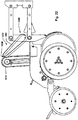
- FIG. 1 An agricultural seeding machine 10 is shown in FIG. 1 as a row crop planter.
- Seeding machine 10 has a central frame 12 on which are mounted a plurality of individual planting units 14.
- the seeding machine 10 has a fore-aft direction shown by the arrow 15 and a transverse direction shown by the arrow 17.
- Each planting unit 14 is coupled to the central frame 12 by a parallel linkage 16 so that the individual planting units 14 may move up and down to a limited degree relative to the frame 12.
- Large storage tanks 13 hold seed that is delivered pneumatically to a mini-hopper on each planting unit.
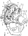
- Each planting unit 14 has a frame member 18 ( FIG. 2 ) to which the components of the planting unit are mounted.
- the frame member 18 includes a pair of upstanding arms 20 at the forward end of thereof.
- the arms 20 are coupled to the rearward ends of the parallel linkage 16.
- Furrow opening disks (not shown) are attached to shaft 22 in a known manner to form an open furrow in the soil beneath the seeding machine into which seed is deposited.
- Closing and packing wheels (not shown) are also mounted to the frame member 18 in a known manner to close the furrow over the deposited seed and to firm the soil in the closed furrow.
- a seed meter 24 and a seed delivery system 400 are also attached to the frame member 18 of the planting unit.
- the meter 24 includes a housing 30 ( FIG. 3 ) and a cover 34.
- the housing 30 and the cover 34 are coupled to one another by complementary hinge features 36 and 38 (see FIG. 5 ) on the housing and cover respectively.
- Hinge feature 36 includes a pivot pin 37 coupled to the housing while the feature 38 is an integrally formed hook that wraps around the pivot pin allowing the cover 34 to pivot about the axis of the pin 37.
- An elastomeric latch member 40 is coupled to the housing 30 and has an enlarged portion 42 that is seated into a socket 44 formed in the cover to hold the cover in a closed position on the housing 30.
- the housing 30 is formed with a second hinge element in the form of a pivot pin 46 ( FIG. 3 ). Pivot pin 46 is seated into a hook member 48 ( FIG. 4 ) of the mounting frame 50 attached to the frame member 18. This allows the seed meter 24 to pivot relative to the planting unit frame member 18 about an axis 52.
- a drive spindle 54 is carried by the housing 30 and has a drive hub 56 ( FIG. 5 ) on the end thereof. The spindle 54 couples to the output shaft 58 of electric motor 60 to drive the seed meter when in the assembled position shown in FIG. 3 .
- the seed meter 24 is coupled to the delivery system by a latch mechanism 68 including a metal rod 70 having a hook at one end seated into an aperture in the meter housing 30 when latched.
- the delivery system further has a mounting hook 72, partially shown in FIG. 2 , which attaches to the planting unit frame member 18 to support the delivery system.
- the delivery system 400 is driven by an electric motor 80, also carried by the mounting frame 50.
- the output shaft of motor 80 is connected to the delivery system through a right-angle drive 82. While electric motors have been shown to drive both the seed meter and the seed delivery system, it will be appreciated by those skilled in the art that other types of motors, such as hydraulic, pneumatic, etc. can be used as well as various types of mechanical drive systems.
- a metering member 100 of the seed meter is shown in greater detail.
- These metering member 100 is shown as a single piece, concave bowl shaped body.
- the bowl shaped body has a base portion 102 from which extends a sidewall 104.
- Sidewall 104 terminates in an outer edge 106.
- the sidewall has a radially inner surface 108 and a radially outer surface 110.
- Adjacent the outer edge 106, the sidewall has a rim portion 112 shown by the bracket in FIG. 6 .
- the rim portion 112 extends radially outwardly and axially toward the outer edge 106.
- the metering member 100 is mounted in the meter housing for rotation in the direction of the arrow 118 in FIG. 6 .
- individual seeds from a seed pool 120 located at a bottom portion of the metering member are adhered to the apertures 114 on the inner surface 108 of the sidewall and sequentially carried upward to a release position 164 at an upper portion of the metering member.
- the inner surface is also known as the seed side of the metering member.
- a series of raised features or projections extend from the inner surface 108 of the sidewall 104 typically with one paddle located behind each aperture 114 in the direction of rotation.
- Each paddle forms a confronting surface 124 behind the associated aperture in the direction of rotation to push the seed adhered to the aperture into the delivery system as described below.
- it is the rim portion 112 of the metering member that performs the function of drawing individual seeds from the seed pool and sequentially moving seed to the release position to supply seed individually to the seed delivery system 400.
- the base portion 102 of the metering member contains a central drive aperture 130 ( FIG. 5 ) used to mount the metering member on a rotational drive hub 56 for rotation about the axis 132 in a manner similar to mounting a flat seed disk in a seed meter as is well known.
- the metering member 100 When mounted to the housing 30, the metering member 100 cooperates with the housing to form a trough to hold the seed pool 120 as described more fully below.
- the axis 132 is inclined to both a horizontal plane as well as to a vertical plane extending fore and aft of the seeding machine and a vertically plane extending transversely to the seeding machine.
- the metering member 100 is shown in a sectional view.
- the base portion 102 is a generally planar while the rim portion 112 of the inner surface of the sidewall 104 is outwardly flared, that is, extending both radially outward and axially.
- the rim portion is frusto-conical.
- the inner surface of the sidewall rim portion 112 may be frusto-spherical in shape.
- the rim portion 112 has been shown as being outwardly flared, the rim portion could be generally cylindrical without any outward flair, that is, extending only axially.
- the metering member 100 can be formed as one piece or constructed of multiple pieces.
- the metering member can be most easily molded of plastic such as polycarbonate, nylon, polypropylene or urethane. However, other plastics can be used as well as other materials such as metal, etc.
- the metering member 100 is sufficiently rigid to be self-sustaining in shape without additional supporting structure. This is in contrast to the flexible belt metering member shown in U.S. Pat. No. 2,960,258 where it be belt member is preferably of a flexible elastomeric material and is supported within a support ring. Being self-sustaining in shape, the metering member does not need any supporting structure to hold a shape.
- the metering member may be rigid or the metering member may be flexible to change shape when acted upon in a manner similar to the flexible seed disk of U.S. Pat. No. 7,661,377 .
- the metering member 100 can be mounted to a drive hub through the central drive aperture 130 in the base portion 102. Mounting through the central drive aperture 130 provides both mounting support of the metering member as well as the rotational drive of the metering member.
- support for the metering member can be provided on the outer surface of the sidewall.
- a groove may be formed in the outer surface of the sidewall to receive rollers that support the metering member. If the groove is also formed with drive teeth, one of the rollers could be driven by a motor to rotate the metering member. With such alternative arrangements possible, it is not necessary that the metering member have a base portion. The function of metering seed is performed by the sidewall and thus, the sidewall is the only required portion of the metering member.
- the metering member 100 when mounted in the meter housing, is oriented at an incline to the vertical as shown.
- the apertures 114 lie in a plane 150 inclined at an angle ⁇ relative to vertical.
- an upper portion 148 of the metering member overhangs or extends beyond a lower portion 154.
- this allows access to the upper portion 148 of the metering member for the mechanical seed delivery system 400.
- the angle ⁇ is approximately 24°. However, any angle will suffice as long as the upper portion 148 extends beyond the lower portion sufficiently for access for the seed delivery system from below the metering member at the seed release position.
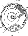
- the seed pool 120 is formed at the bottom of the metering member 100 as shown in FIG. 9 .
- Vacuum is applied to the outer surface 110, causing individual seeds to be adhered to the apertures 114 as the apertures travel through the seed pool.
- seed is moved upward to a release position 164 at the upper portion 148 of the metering member.
- the release position is slightly past the top or 12 O'clock position on the circular path of travel of the seed such that the seed is moving somewhat downward at the release position. This facilitates the seed's entry into the delivery system as more fully described below.
- the delivery system is off center relative to the metering member providing clearance between the delivery system and the seed meter drive.
- the inner surface of the rim portion of the metering member is facing downward such that seed is adhered beneath the metering member or is hanging from the metering member. See FIG. 10 .
- the seed delivery system 400 is also positioned beneath the upper portion of the metering member at the release position 164 to take the seed from the metering member as shown in FIG. 10 .
- Delivery system 400 includes a housing 402 having a left sidewall 404 (see FIG. 19 ) and a right sidewall 406 (see FIG. 3 ).
- the terms left and right are used in relationship to the direction of travel of the seeding machine shown by the arrow 408.
- Connecting the left and right sidewalls to one another is an edge wall 410.
- An upper opening 416 is formed in the edge wall and sidewalls to allow seed to enter into the housing 402.
- a lower opening 418 is provided at the lower end forming a discharge location 413 for the seed.
- a pair of pulleys 420 and 422 are mounted inside the housing 402. (It will be understood that other configurations may also be possible.
- delivery system 400 may be oriented horizontally, rather than vertically, or at various deviations from horizontal or vertical.
- opening 416 may be viewed as an inlet opening to delivery system 400, and opening 418 may be viewed as an exit opening.
- the pulleys a support a belt 424 for rotation within the housing.
- One of the two pulleys is a drive pulley while the other pulley is an idler pulley.
- the belt has a flexible base member 426 to engage the pulleys.
- Elongated bristles 428 extend from the base member 426.
- the bristles are joined to the base member at proximal, or radially inner, ends of the bristles.
- Distal, or radially outer, ends 430 of the bristles touch or are close to touching the inner surface of the housing edge wall 410.
- a seed 152 is at the release position on the metering member 100 and has just been inserted into the bristles 428 of the delivery system.
- the rim portion 112 of the metering member sidewall 104 is generally tangent to the stationary inner surface 412 across which the brush bristles 428 sweep.
- the surface 412 is on a latch portion 66 of the housing 30.
- the surface 412 is a continuation of the inner surface 414 of the delivery system housing 402.
- FIG. 11, 12 and 15 show embodiments which do not form part of the invention and rather represent background art that is useful for understanding the invention.
- the seed Prior to release of the seed from the metering member, the seed is moving in the direction of vector 160 which is slightly downward into the bristles 428. With reference to FIG. 13 , the vector 160 of the seed direction is at an angle 161 of about 60° to the length of the bristles 428 shown by the arrow 176. As shown in FIG. 11 , the brush belt is positioned so that seed enters the bristles at the corner of the brush belt. The brush can be positioned so that the seed enters the brush through the distal ends of the bristles or through the side of the bristles.
- FIG. 14 The relationship between the seed direction vector 160 on the metering member and the seed direction vector 438 when the seed is first in the brush belt is shown in FIG. 14 illustrating the two vectors in the plane containing both vectors at the release position 164.
- the angle 163 between the vectors is at least 35° and preferably between 50° and 80°. This shows the cross-feed of the seed into the bristles, meaning that the seed, prior to the release position is moving substantially in a different direction than the brush bristles are moving.
- FIG. 3 of the previously mentioned US patent application 2010/0192819-A1 where the seed on the metering disk at the release is moving in substantially the same direction as the brush bristles.
- This is also the relationship by which the bristles sweep over the inner surface of the sidewall relative to the travel direction of seed.
- FIGS. 11 and 12 show a blocking member 162 carried by the meter housing 30.
- Blocking member 162 is positioned adjacent a path of travel of seed 152 leading to the release position 164 and prevents movement of seed from the metering member prior to reaching the release position. Once the seed has passed the end 174 of the blocking member 162, the seed is free to move with the brush bristles in the direction of the vector 438 in FIG. 10 .
- the blocking member ensures that the seed is consistently feed into the brush belt in the center of the belt, widthwise, rather than allowing the seed to enter the belt at random positions across the belt width. As shown in FIG.
- the blocking member is located beneath the sidewall 104 of the metering member 100 between the paddles 116 and the outer edge 106 of the metering member.
- the confronting surfaces 124 of the paddles 116 push seed into the brush bristles.
- the paddles or projections 116 travel further into the brush bristles, that is deeper into the bristles from their distal ends, as the projections cross the width of the brush as seen in FIG. 11 .
- the seed is swept over the inner surface of the metering member, from the apertures 114 to the outer edge 106 of the metering member in the direction of the vector 438.
- the delivery system could be arranged to sweep seed in the opposite direction, that is, away from the outer edge 106 of the metering member.
- an ejector 166 carried by the cover 34 rides on the outer surface of the metering member rim portion. See FIGS. 11, 12 and 15 .
- the ejector 166 is in the form of a star wheel having a number of projections 168.
- the projections 168 extend into the apertures 114 from the outer surface 110 of the sidewall 104 and force seed out of the apertures 114.
- the ejector is caused to rotate by rotation of the metering member 100 due to the projections 168 engaging in the apertures 114.
- the ejector is mounted to the cover 34 via a pivot arm 170 and bracket 171.
- the ejector 166 is biased against the metering member by a spring 172.
- a flexible seal 180 is shown on the inner side of the cover 34. This seal bears against the outer surface 110 of the metering member 100 forming a vacuum chamber within the interior 182 of the seal.
- a first portion 184 of the seal is spaced radially further out on the metering member than is the second portion 186 of the seal. In the area of the seal first portion 184, vacuum is applied to the apertures 114, causing seed to adhered thereto. There is no vacuum applied to the apertures adjacent and outside of the seal second portion 186.
- a port 188 in the cover 34 is adapted to connect the interior of the cover to a vacuum source in a known manner for a vacuum seed meter.
- the seed release position 164 is within the vacuum chamber.
- the inside of the housing 30 is shown.
- the housing includes a central boss 302 for the drive spindle 54.
- the housing also includes an opening 304 to receive seed from a mini-hopper, not shown, mounted to the outside of the housing and surrounding the opening 304.
- Below the opening 304 the housing wall forms a ramp 306 extending downward toward the lower end 308 of the housing. The ramp cooperates with the inner surface 108 of the metering member to hold the seed pool 120.
- the housing includes an inward projection 310 forming a cavity 314 ( FIG. 17 ) on the outside of the housing into which the upper end if the delivery system 400 is placed.
- the projection is open at the upper end, forming a downward looking opening 312 from the interior of the housing to the exterior. This opening 312 allows the brush belt 424 to access the inner surface of the 108 of the metering member and carry seed from the housing.
- FIG. 17 illustrates the orientation of the metering member and the cooperation of the housing 30 and metering member 100 to form a trough for the seed pool 120 at the lower end of the metering member.
- FIG. 17 shows the orientation of the metering member when the seeding machine 10 is on level ground.
- the sidewall 104 is inclined to the vertical such that the inner surface 108 is at an angle d to the vertical vector 126.
- the inner surface is approximately 21° from vertical.
- the orientation of the housing adjacent the metering member, forming the other side of the trough, is not critical.
- Seed from the seed pool 120 sits on top of the inner surface 108 and a component of the force of gravity is perpendicular to the inner surface 108.
- the inner surface 108 remains inclined and gravity still has a component perpendicular to the inner surface. This is in contrast to a typical disk seed meter shown in FIG. 18 with a vertically oriented disk 320 cooperating with a housing wall 322 for form a seed pool 324. If this meter is tilted counterclockwise as viewed, seed from the pool will still bear against the disk.
- the inner surface 108 has an angle f to a downward vertical vector 128 in the range of 50° to 90° with the closer to 90° being the better for hand-off of seed from the metering member to the brush belt. As shown, the angle f is approximately 68°.
- the different orientations of the inner surface 108 relative to vertical at the seed trough and at the release position is accomplished with a metering member that is rigid. Such variation is not possible with the flat disk metering member shown in FIG. 18 .
- the pressure differential can be created by a positive pressure between the housing 30 and the metering member 100.
- Such a system would require seals between the metering member 100 and the housing 30 to create a positive pressure chamber.
- the cover 34 only serves as a cover for the rotating metering member.
- a pair of doubles eliminators or singulators are attached to the housing 30 along the path of seed from the seed pool to the release position 164.
- the singulators are in the form of brushes 330 and 332 ( FIGS. 5 and 9 ).
- Brush 330 has bristles extending substantially axially and brushes seed on the apertures 114 by extending inwardly from the outer edge 106 of the metering member.
- the bristles of brush 330 are of varying length, to engage the seed at several discrete locations along the length of the brush 330.
- the brush 332 has bristles extending substantially radially and engaging the inner surface of the metering member sidewall inside of the paddles 116 and extend along the sidewall to the apertures 114. Both brushes 330 and 332 act to slightly disturb seed on the aperture and cause excess seed to fall off. Once removed, the excess seed falls back to the seed pool 120.
- the brushes can be fixed in position or they can be adjustable to change the degree to which the brushed disturb seed on the metering member.
- a third brush 334 is shown which extends generally radially of the metering member. The brush 334 serves to define a boundary to the seed pool 120.
- the brushes 330, 332 and 334 are mounted to the housing 30.
- the delivery system controls the movement of seed from the seed meter to the discharge location.
- the seeds are held in the bristles such that the seeds can not move vertically relative to the bristles 428 or relative to other seeds in the delivery system. Particularly, during travel of the seeds along the vertical side of the delivery system, the seeds are held on at least the top and bottom of the seeds to prevent any relative movement between the seed and the brush belt. Thus, the relative position of the seeds to one another is not affected by dynamics of the planting unit while moving across a field.
- the seed is carried by the bristles from the upper opening 416 to the lower opening 418 with the movement of the seed controlled at all times from the upper opening to the lower opening. (As noted above, other orientations may also be possible. As such, opening 416 may be generally viewed as an inlet opening, and 418 may be generally viewed as an exit opening for delivery system 400.)
- the lower opening 418 of the delivery system housing is positioned as close to the bottom 446 of the seed trench or furrow 448 as possible. As shown, the lower opening 418 is near or below the soil surface 432 adjacent the seed furrow.
- the bottom of the delivery system should be no more than one or two inches, (2.5-5 cm) above the soil surface 432. If possible, the lower end of the delivery system should be below the soil surface 432.
- the housing edge wall 410 forms an exit ramp 434 at the lower opening 418.
- the lower opening 418 and the ramp 434 are positioned along the curve in the belt path around the pulley 422.
- the seed being carried by the bristle's distal ends, increases in linear speed around the pulley 422 as the distal ends of the bristles travel a greater distance around the pulley 422 than does the base member 426 of the belt. This speed difference is shown by the two arrows 440 and 442.
- the seed has a velocity shown by the vector V.
- This velocity has a vertical component V v and a horizontal component V H .
- the belt is operated at a speed to produce a horizontal velocity component V H that is approximately equal to, but in the opposite direction of, the seeding machine forward velocity shown by arrow 408.
- the horizontal velocity of the seed relative to the ground is zero or approximately zero. This minimizes rolling of the seed in the seed trench.
- Seed can be inserted into the brush bristles at essentially an infinite number of positions. This enables the brush to be operated at the speed necessary to produce the desired horizontal velocity component to the seed, independent of the seed population.
- the seed meter on the other hand, must be operated at a speed that is a function of both the forward travel speed of the seeding machine and the desired seed population. Because the belt 424 can be loaded with seed at essentially an infinite number of positions, the belt speed can be operated independently of the seed meter speed. This is not the case with other seed delivery systems, such as that disclosed in U.S. Pat. No. 6,681,706 where the delivery system of FIG. 2 has a belt with flights to carry the seed. The belt speed must be timed to the seed meter speed to ensure that one or more flights pass the seed meter for each seed that is discharged from the meter.
- the interior of the lower portion of delivery system housing is shown in FIG. 19 .
- the delivery system housing 402 is a two-piece housing having an upper housing member 460 and a lower housing member 462.
- the lower housing member carries the lower pulley 422.
- the lower housing member has an upwardly extending rod portion 464 that slides within a channel formed by walls 466 and 468 in the upper housing member. Springs, not shown, push downward on the rod portion 464 to bias the lower housing member downward.
- the brush belt 424 wrapped about the pulleys 420 and 422, holds the upper and lower housing members together.
- the belt 424 is tensioned by the springs acting on the rod portion 464.
- a U-shaped metal strip 470 is attached to the upper housing member 460 and bridges the gap 472 between the upper and lower housing members to provide a continuous surface for holding seed in the housing between the upper opening 416 and the lower opening 418.
- the metal strip has a tab at the upper end thereof bent over and inserted into a slot 474 in the upper housing member 460 to hold the metal strip 470 in place. If needed, a fastener, such as a nut and bolt, may be placed through the rod portion 464 and the upper housing member 460 to fix the upper and lower housing members together.
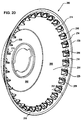
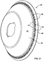
- the metering member 100 is intended for soybeans and other crops planted with a fairly close seed spacing. Corn, which is planted at a greater seed spacing uses a metering member 200 shown in FIGS. 20 and 21 .
- Metering member 200 is constructed in a similar fashion as metering member 100 and like components are given the same reference numeral with the addition of 100. However, metering member 200 has half the number of apertures 214 as the metering member 100. To avoid the need to replace the ejector 166 when changing metering members, the metering member 200 has recess 226 extending into the sidewall 204 on the outer surface 210 of the sidewall between each aperture 214.
- the recesses 226 provide clearance for the projections 168 of the ejector 166 that are arranged to be inserted in each aperture 114 of the metering member 100.
- the recesses 226 are not open to the inner surface 208 of the sidewall 204.
- the projections 228 and the paddles 216 can be formed as a single projections extending from the inner surface 208.
- a belt meter 1200 is shown schematically to illustrate the relationship of the belt 1250 relative to the row unit structure.
- the belt 1250 lies in a plane that is inclined relative to all three axes, that is the plane of the belt is inclined relative to a vertical fore and aft plane, inclined relative to a vertical transverse plane and inclined relative to a horizontal plane.
- the seed pickup region 1206 is positioned at the lower end of the belt 1250 while the seed release position or location 1208 is located at the upper end of the belt 1250.
- the seed is removed from the belt 1250 at the release location by a seed delivery system 1210.
- the seed delivery system 1210 is like seed delivery system 400 described above containing a brush belt 1312 to grip and carry seed.
- the seed delivery system 1210 moves the seed from the seed meter belt to the lower end of the row unit between the furrow opening disks where it is deposited into the furrow formed in the soil.
- the seed meter 1200 is described fully below with reference to FIGS. 23-30 .
- the seed meter 1200 has a frame member 1220 in the form of a plate which is mounted to the row unit frame in a suitable manner.
- the frame member 1220 supports the upper idler pulley 1256 and the lower drive pulley 1260 about which the belt 1250 is wrapped.
- a gearbox and drive motor (not shown) are coupled to the shaft 264 to drive the pulley 1260 and belt counterclockwise as viewed in FIG. 23 and shown by the arrow 1261.
- the frame member 1220 also carries a vacuum manifold 1262 having a hollow interior vacuum chamber 1266.
- a vacuum port 1263 extends from the opposite side of the vacuum chamber through the frame member 1220.
- the manifold 1262 has an outer wall 11268 ( FIG. 25 ) containing a main slot 1270 extending the length of the outer wall.
- a secondary slot 11272 extends only a short portion of the length of the outer wall.
- the belt 1250 has an outer seed engaging face or side 11251.
- the belt 1250 includes a row of first apertures 11252 which overlie the slot 1270 in the manifold 1262.
- the apertures 11252 to extend through the belt, allowing air to flow through the belt.
- the belt further has a plurality of features 11254 formed as ribs extending from the seed face 1251.
- the features 1254 each for a confronting face 1255 shown in FIG. 29 facing in the travel direction of the belt. In this embodiment, the feature 1254 forms the confronting face 1255 extending outward from the seed side 1251 of the belt. In the embodiment shown, the features 1254 do not extend laterally to both side edges of the belt, but leaves a flat edge zone 1257 along one edge of the belt.
- An optional second row of apertures 1258 in the belt are positioned to pass over the secondary slot 1272 in the manifold outer wall 1268.
- the apertures 1258 are only in communication with the vacuum chamber 1266 for the short portion of the path of the apertures 1258 over the slot 1272.
- a housing 1276 is attached to the frame member 1220 and closely positioned to the belt 1250. A portion 1277 of the housing 1276 overlies the flat edge zone 1257 of the belt.
- the housing 1276, the belt 1250, and a cover 1278 (shown in FIG. 28 ) form a small chamber 1279 which holds a pool of seed 1280.
- a brush 1282 mounted to the housing 1276 sweeps across the face 1251 of the belt and seals the chamber 1279 at the location where the belt enters the chamber to prevent seed from escaping the chamber 1279. Seed enters in the chamber 1279 through a suitable port, not shown, in the housing 1276 or housing cover 1278.
- the belt 1250 and housing 1276 form a V-shaped trough for the seed pool that extends uphill in the direction of belt travel.
- the confronting faces 1255 formed by the features 1254 of the belt engage the seed in the pool to agitate the seed creating a circular flow of seed as shown by the broken line 1284 of FIG. 24 . Since the belt forms one side of the V-shaped trough, seed will always remain in contact with the belt regardless of tilt or inclination of the planter, as long as sufficient seed is present in the seed pool.
- An advantage of the seed meter is that when the vacuum shut off, seed on the belt falls back into the seed pool. This is in contrast to disk meters where a portion of the seed on the disk above the seed tube will fall to the ground upon vacuum shut-off.
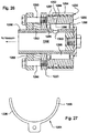
- the idler pulley 1256 is supported by a bearing set 1285 on a tube 1286 ( FIG. 26 ).
- a flange 1288 welded to the tube 1286 is attached to the frame member 1220 by bolts 1290.
- a spacer 1292 is positioned between the flange and frame member 1220.
- the idler pulley 1256 has a groove 1294 in its outer periphery which is in line with the belt apertures 1252.
- Channels 1296 extend radially through the pulley 1256 to an annular chamber 1298 surrounding the tube 1286.
- An opening 1300 in the tube 1286 provides communication between the chamber 1298 and the hollow interior 1302 of the tube.
- the tube is connected to the vacuum source whereby the vacuum is applied to the apertures 1252 in the belt as the belt travels over the pulley 1256.
- a fork 1304 is attached to the frame member 1220 with tines 1306 seated in the groove 1294 in the idler pulley. The tines filled the groove 1294 to cut off the vacuum and create the seed release location 1208. The tines 1306 extend from the seed release location to the vacuum manifold in the direction of rotation of the idler pulley to seal the vacuum chamber and the groove in the idler pulley.
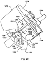
- the housing cover 1278 mounts to the manifold and covers the open side of the housing 1276 as shown in FIG. 29 .
- a doubles the eliminator 1310 is mounted to the housing cover and, when assembled, lies on top of the belt 1250.
- the doubles eliminator 1310 is roughly wedge-shaped and progressively increases in width in the travel direction of the belt to increase its coverage over the apertures 1252.
- the doubles eliminated 1310 causes doubles or multiples of seed to be removed from the belt resulting in a single seed covering each aperture 1252.
- the confronting face 1255 engage and agitate seed in the seed pool at the bottom of the housing 1276.
- Seed from the seed pool will be adhered to the belt at each aperture 1252 due to the vacuum applied to the apertures from the interior of the manifold 1262 or by positive air pressure on the seed side of the belt.
- the main slot 1270 the seeds will continue to be retained on the belt as the belt travels from the seed pick-up region 1206 to the idler pulley 1256. Due to the groove in the idler pulley, the vacuum is maintained on the apertures as the belt travels around the pulley until the seed and the aperture reaches the tine 1306 of the fork 1304.
- the vacuum Upon reaching the tine 1306, the vacuum is terminated and the seed is released from the belt 1250.
- the seed can be mechanically removed from the belt or removed by a combination of vacuum termination and mechanical removal or the seeds can be removed mechanically while the vacuum is still applied.
- the second row of apertures 1258 will also operate to retain a seed therein while the aperture 1258 travels over the shorter slot 1272. By picking up seed, the apertures 1258 act to further agitate the seed pool. In addition, when the apertures 1258 reach the downstream end 273 of the secondary slot 1272, the seed is released from the belt. The release location from the aperture 1258 causes the seed to pass over one of the apertures 1252 as the seed falls. If the aperture 1252 failed to pick-up a seed and is empty, the falling seed may be retained thereon. If the aperture 1252 is not empty, but instead picked-up multiple seeds, the falling seed may collide with the multiple seeds and assist in removing one or more of the multiple seeds. In this fashion, the falling seed operates to avoid errors in terms either no seed or multiple seeds on an aperture 1252.
- the seed delivery system 1210 includes an endless member also wrapped around pulleys and contained within a housing 1322.
- the housing has an upper opening 1324 through which seed is admitted into the delivery system.
- the endless member is shown in the form of a brush belt 1312 having bristles 1314 that sweep across the face 1251 of the belt 1250 to remove the seed therefrom.
- a transition plate 1316 is positioned adjacent the belt 1250. The transition plate has a curved first edge 1318 abutting the edge of the belt as the belt travels around the idler pulley. The brush belt bristles will engage a seed in the aperture 1252A at the location shown in FIG.
- the confronting face 1255 behind the aperture 1252A serves as a back stop to prevent the brush from knocking the seed off the metering belt.
- the confronting face 1255 pushes the seed into the brush bristles.
- the downward extending tab portion 1323 of the transition plate projects into the housing of the delivery system 1210 to allow the brush to continuously trap seed as the seed moves off the belt 1250, over the transition plate 1316 and into the interior of the delivery system housing where the seed is trapped by the brush bristles and the interior surface of the delivery system housing 1322.
- a guide 1325 projects from the surface of the transition plate to guide the seed and keep the seed from being swept off the meter belt prematurely.
- the guide forms an upstanding wall having a first portion 1326 adjacent the path of seed on the belt 1250 immediately prior to the release position 1208.
- a second portion 1328 of the upstanding wall extends in the direction of seed travel in the brush belt 1312. Seed must pass the corner or bend 1330 in the upstanding wall before it can be moved off the meter belt 1250 by the seed delivery system.
- the guide 1325 and blocking member 162 ensure seed entry into the brush belt in a consistent manner and in the same location across the width of the brush belt. This consistent hand-off of seed from the seed meter to the seed delivery system helps to improve placement accuracy of the seed in the furrow in the soil.
- blocking member 162 may be configured as a transitional blocking member including a segue or transition portion, which may deflect a portion of the bristles of a brush belt (e.g., bristles 428 of delivery system 400) as a seed is captured by the bristles for transport.
- seeds may be carried by metering member 100 from seed pool 120 toward release position 164 (e.g., as retained on metering member 100 by way of exposure of the seeds to a pressure differential through apertures 114).
- release position 164 seed (e.g., seed 152) may be considered as moving in a first direction (e.g., along the path of apertures 114 of metering member 100).
- Transitional blocking member 162a may be secured near release position 164 and may include one or more passages through blocking member 162a for bristles 428 of delivery system 400.
- One or more of these passages may, in turn, include a segue or transition portion configured to temporarily deflect a portion of bristles 428 and, in certain embodiments, gradually release the deflected bristles to a generally un-deflected configuration.
- ejector 166 may cause seed (e.g., seed 152) to be released from the associated aperture 114 (and thereby, at least in part, from metering member 100). Seed 152 may then be swept off of metering member 100 by bristles 428 and carried by bristles 428 through the one or more passages through blocking member 162a and onward through the seed-transport path of delivery system 400 (e.g., downward to lower opening 418 and discharge location 413. As seed 152 is initially carried away from release position 164 by bristles 428, seed 152 may be considered as moving in a second direction (e.g., along the path of bristles 428 of delivery system 400).
- seed e.g., seed 152
- FIGS. 33-35 various aspects of example transitional blocking member 162a are depicted.
- FIGS. 33 and 34 depict transitional blocking member 162a from the downstream side, with respect to movement of bristles 428 (i.e., viewing transitional blocking member 162a from the right side, with respect to FIG. 32 )
- FIG. 35 depicts transitional blocking member 162a from the upstream side, with respect to movement of bristles 428 (i.e., viewing transitional blocking member 162a from the left side, with respect to FIG. 32 ).
- seed e.g., seed 152
- seed 152 may be generally viewed as traveling through transitional blocking member 162a, as carried by bristles 428, in a direction that is generally out of the page, with respect to FIGS. 33 and 34 , and in a direction that is generally into the page, with respect to FIG. 35 .
- transitional blocking member 162a may include blocking face 1400 with edges 1402 and 1404. Transitional blocking member 162a may be fixed with respect to metering member 100 (e.g., mounted to housing 30) such that face 1400 may be oriented across the path of bristles 428, at least in part, and adjacent to the path of seed as the seed is carried in the first direction by metering member 100.
- bristles 428 (depicted in dotted lines in FIGS. 34 and 35 ) may press a seed (e.g., seed 152) against blocking face 1400 as seed 152 passes across face 1400 (as carried by metering member 100).
- blocking face 1400 may prevent seed (e.g., seed 152) from moving in the second direction (i.e., with bristles 428) as long as the seed is adjacent to blocking face 1400.
- Edge 1402 of blocking face 1400 may be viewed as defining, at least in part, the entrance into a seed passage through transitional blocking member 162a, through which a seed (e.g., seed 152) may be carried by bristles 428 (i.e., after bristles 428 have swept seed 152 off of metering member 100).
- edge 1402 of blocking face 1400 may be located immediately preceding release position 164 with respect to the first-direction travel of seed 152 (i.e., immediately upstream of release position 164, from the perspective of seed 152 moving with metering member 100 in the first direction).
- bristles 428 may contact a seed (e.g., seed 152) as the seed moves across blocking face 1400, but blocking face 1400 may prevent the seed from moving through transitional blocking member 162a until the seed has moved past blocking face 1400 (e.g., as carried by metering member 100). Once the seed (e.g., seed 152) has moved past blocking face 1400, the seed may then be carried through transitional blocking member 162a by bristles 428 (i.e., because the path of seed 152 in the second direction may no longer be impeded by blocking face 1400).
- a seed e.g., seed 152
- transitional blocking member 162a includes adjacent passages, defined in part by blocking face 1400 and edges 1402 and 1404.
- transitional blocking member 162a includes seed passage 1406 and transition passage 1408, which passages 1406, 1408 are generally adjacent to each other. Passages 1406 and 1408 are generally extending through transitional blocking member 162a in the second direction (i.e., the direction of travel of bristles 428).
- Transition passage 1408 is defined, at least in part, by transition surface 1410, which extends from (upstream) edge 1404 to (downstream) edge 1412. Transition surface 1410 extends into the path of bristles 428 between edges 1404 and 1412, in order to deflect a portion of bristles 428 away from transitional blocking member 162a. Transition surface 1410 is configured to gradually release the deflected bristles 428 to an un-deflected configuration as the deflected portion of bristles 428 travels between edges 1404 and 1412 (i.e., as driven by delivery system 400).
- Bristles 428 may be deflected in various ways by transitional blocking member 162a.
- edge 1404 blocking face 1400, and transition surface 1410, for example, free ends 1426 of bristles 428 (see, e.g., FIG. 36A ) may be deflected at edge 1410 either downward (from the perspective of FIGS. 36A and 36B ) or radially inward (from the perspective of belt 424 and pulley 420 in FIG. 32 ) in order to pass blocking face 1400 at edge 1404.
- the transition surface 1410 includes a curved surface that releases bristles 428 gradually upward (from the perspective of FIGS.
- Bristles 428 may also be deflected in various other ways.
- inner deflection surface 1442 or other surfaces may deflect bristles 428 inward (i.e., toward the centerline of bristles 428, from a perspective transverse to the path of travel of bristles 428) as bristles 428 pass through transitional blocking member 162a.
- bristles 428 may be naturally deflected, to a certain degree, by the movement of bristles 428 along the second direction within delivery system 400 (e.g., due to air resistance, inertial effects, incidental contact with the housing of delivery system 400, and so on). In this light, and in the context of transitional blocking member 162a, bristles 428 may be viewed as "un-deflected” once the bristles are no longer deflected by contact with transition surface 1410 (or another component of transitional blocking member 162a).
- transition surface 1410 may be a continuously curved surface, which may allow the deflected portion of bristles 428 to smoothly (and gradually) transition from a deflected configuration (i.e., at edge 1404, where the portion of bristles 428 is first deflected by blocking face 1400) to an un-deflected configuration (i.e., at edge 1412, where the deflected portion of bristles 428 passes the downstream termination of transition surface 1410).
- transition surface 1410 may be configured, for example, as a parabolic, hyperbolic, polynomial, circular, or other curve.
- transition surface 1410 may also be possible, including various continuous linear or non-linear geometries (not shown), termination of transition surface 1410 (and corresponding return of bristles 428 to an un-deflected configuration) upstream of edge 1412, and so on.
- transitional blocking member 162a may also be included in transitional blocking member 162a.
- recess 1420 may be formed in downstream surface 1422.
- Recess 1420 (or other geometry of transitional blocking member 162a) may assist, for example, in the routing of seeds back towards seed pool 120 (e.g., if the seeds are not properly captured by bristles 428 for transport into the delivery system), or in providing a relatively gradual (as opposed to a sharply edged) interface for bristles 428 with transitional blocking member 162a (e.g., to reduce wear on bristles 428).
- Recess 1420 may also aid inner deflection surface 1442 in deflecting bristles 428 laterally (i.e., toward the centerline of bristles 428) as bristles 428 pass into and through transitional blocking member 162a. This latter functionality, for example, may be useful if bristles 428 begin to splay laterally outward over the life of delivery system 400, as well as in various other instances.
- transitional blocking member 162a and related components are depicted with seed 152 at release position 164.
- a portion of bristles have been removed in order to show various features of the system.
- a seed e.g., seed 152
- the seed may be carried along upstream surface 1418 and across blocking face 1400 by metering member 100.
- the seed may be ejected from metering member 100 by ejector 166.
- the seed may be carried into seed passage 1406 by bristles 428.
- bristles 428 may be deflected by blocking face 1400 (and transition surface 1410) for passage into transition passage 1408.
- the remaining portion of bristles 428 e.g., bristles 428b
- bristles 428b may not be deflected (or deflected to a lesser degree) as it passes into and through seed passage 1406 and may, accordingly, carry seed 152 with bristles 428b in a relatively un-deflected configuration.
- bristles 428a may also engage with seed 152 in order to carry seed 152 along the seed path defined by delivery system 400.
- bristles 428a may gradually return to an un-deflected configuration, sweeping up to enclose a portion of seed 152, such that at (or near) edge 1412, seed 152 may be carried (and at least partially enclosed) by both portions 428a and 428b of bristles 428.
- transitional blocking member 162a may be selected based upon characteristics of bristles 428, the type of seed to be processed (e.g., the type of seed represented by seed 152), or various other factors. In certain embodiments, for example, it may be desirable that seed 152 be carried by bristles 428, within delivery system 400, roughly at the mid-line of bristles 428 from a perspective transverse to the direction of motion of bristles 428 (i.e., left-to-right in FIGS. 36A and 36B ).
- blocking face 1400 may be configured to extend along metering member 100 the first direction (i.e., the direction of travel of seed 152 at release point 164) to approximately a mid-line of bristles 428 (i.e., a mid-point of bristle width 1416).
- blocking face 1400 may extend to a point just short of the mid-line of bristles 428.
- blocking face 1400 may extend to a point that is half of a nominal or average seed diameter (e.g., nominal seed half-diameter 1424) short of the mid-line of bristles 428. Such a point may be indicated in FIGS. 36A and 36B by line 1414. In this way, when seed 152 clears blocking face 1400 and is engaged for transport by bristles 428b, the center of seed 152 may be approximately aligned with the mid-line of bristles 428.
- blocking face 1400 (and, accordingly, various configurations of transitional blocking member 162a) may accordingly be selected based upon the nominal or average size of seed to be processed. Average of nominal diameter of seed may be determined in a variety of known ways, including through specifications from seed providers or various standardized measurement techniques.
- the initial extension of blocking face 1400 into bristles 428 may also be determined based upon, at least in part, the nominal or average size (e.g., diameter) of the type of seed to be processed by the planting system.
- blocking face 1400 may be intended to block transport of seed in the second direction (i.e., along the path of travel of bristles 428 as bristles 428 sweep seed off of metering member 100) by bristle portion 428a.
- blocking face 1400 may be configured such that edge 1404 extends into bristles 428 at least as far as a nominal or average diameter of the relevant seed. In this way, for example, as seed 152 passes across blocking face 1400 (i.e., as carried by metering member 100), blocking face 1400 may fully block the movement of seed 152 in the second direction until seed 152 has cleared blocking face 1400 (i.e., at edge 1402). Meanwhile, as also noted above, blocking face 1400 may also deflect bristles 428a for entrance to transition passage 1408.
- FIGS. 37 and 38 depict, respectively, sectional views of example transitional blocking member 162a (along with bristles 428 and other components of planting unit 14) along planes A-A and B-B of FIG. 34 .
- bristles 428a may be viewed as traveling generally to the right in FIG. 37
- bristles 428b may be viewed as traveling generally to the left in FIG. 38 .
- bristles 428a may contact seed 152 and press it against blocking face 1400.
- Blocking face 1400 may accordingly deflect bristles 428a for travel through transition passage 1408 while also, because blocking face 1400 may extend into bristles 428a (through edge 1404) farther than a nominal diameter of seed 152, preventing seed 152 from traveling through transition passage 1408.
- seed 152 continues along its first-direction path (e.g., as carried by metering member 100), it eventually clears edge 1402 and is carried by bristles 428b through seed passage 1406 (e.g., after also being ejected from metering member 100 by ejector 162).
- bristles 428a may gradually return to an un-deflected configuration, with the result that seed 152 may be carried by both bristles 428a and 428b once seed 152 is downstream of transitional blocking member 162a (e.g., downstream of edge 1412).
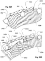
- FIG. 39A may represent the movement of generally un-deflected bristles 428b and seed 152 (at successive points in time, as carried by bristles 428b) through seed passage 1406, while FIG. 39B may represent the movement of generally deflected bristles 428a through transition passage 1408.
- bristles 428b may remain largely un-deflected (or at least less deflected than bristles 428a passing through transition passage 1408).
- bristles 428a may initially be deflected by blocking face 1400, with a gradual return to an un-deflected state being facilitated by transition surface 1410.
- bristles 428a may gradually engage with seed 152 to transport seed 152 (along with bristles 428b) through delivery system 400.
- both portions of bristles 428 may cooperatively transport seed 152, with bristles 428b generally to one side of seed 152 and bristles 428a generally to the opposite side of seed 152.
- such a gradual return from a deflected to an un-deflected state may avoid the formation of gaps or cavities between various of bristles 428a that might result if bristles 428a were instead allowed to abruptly return from a deflected to an un-deflected state.
- gap 1436 could result between the deflected and un-deflected portions of bristles 428c.
- Such a gap could result in poor placement of seed 152 within bristles 428.
- gap 1436 is large enough, seed 152 may fall too deeply into bristles 428c (as shown in FIG. 40 ), which may detrimentally affect subsequent transport and processing (e.g., planting) of seed 152.
- Other detrimental effects on seed placement could also occur, such as off-center seed placement within bristles 428, and so on.
- use of a transitional blocking member e.g., member 162a
- to provide a more gradual return for the deflected portion of bristles 428 (e.g., bristles 428a) from a deflected configuration to an un-deflected configuration may result in better seed placement within bristles 428. This, in turn, may result in better placement of the seed at the point of planting.
- Transitional blocking member 162a may be fixed with respect to metering member 100 in various ways.
- various grommets, bosses or other mounting devices may be provided on transitional blocking member 162a in order to mount transitional blocking member 162a to another component of planting unit 14 (e.g., housing 30).
- bosses 1438 and 1440 may be provided on blocking member 162a, with bosses 1438 and 1440 configured to receive mounting pins, screws or bolts, and so on, in order to secure transitional blocking member 162a to various other components of planting unit 14.
- Various other known connection or mounting means may additionally (or alternatively) be utilized.
- the general orientation of the seed meter and delivery system can differ from that depicted in the figures.
- the figures illustrate a generally vertically oriented delivery system.
- the delivery system can instead be generally horizontal or an arbitrary angle to the horizon. Therefore, any words of orientation, such as various forms of "up”, “down”, “top”, “bottom,” “above,” and “below”, used herein are for the purpose of describing particular embodiments only and are not intended to be limiting of the disclosure.
Description
- The following relates to a planting unit for a seeding machine provided with a seed meter with a metering member that moves seed sequentially along a first path to a release position at which the seed is moving in a first direction and a delivery system adapted to receive seed from the metering member at the release position and control movement of the seed from the seed meter to a discharge location adjacent a seed furrow formed in soil beneath the seeding machine. The delivery system includes a brush belt with flexible bristles, which bristles, at the release position, move seed in a second direction along a second path.
- Various types of seed meters have been developed that use an air pressure differential, either vacuum or positive pressure, to adhere seed to a metering member. The metering member takes seed from a seed pool and sequentially discharges single seeds. (In some cases, multiple seeds may be discharged at a time.) One common type of seed meter is shown in
U.S. Pat. No. 5,170,909 . There, aseed disk 48 contained in a housing is used to meter the seed. The seed pool is positioned on one side of the disk at a lower portion thereof while vacuum is applied to the opposite side of the disk. As the disk is rotated, individual seeds from the seed pool are adhered by the vacuum to apertures that extend though the disk. When the seed reaches a desired release position, the vacuum is terminated, allowing the seed to drop from the disk, through a seed tube to a furrow formed in the soil below. - Another common type of seed meter is shown in
US 2012/067260 A1 , wherein the seed meter having a metering member that moves seed sequentially along a first path to a release position at which the seed is moving in a first direction and a delivery system adapted to take seed from the metering member at the release position and control movement of the seed from the seed meter to a discharge location adjacent a seed furrow formed in soil beneath the seeding machine. The delivery system, at the release position, moves seed in a second direction along a second path. A blocking member located adjacent the first path immediately preceding the release position prevents movement of the seed in the second direction until the seed has passed the blocking member. - Flexible belts have also been used in an air pressure differential seed meter. One example is shown in
US patent application 2010/0192818 A1 . There, a flexible belt having an array of apertures therein is movable along a path in a housing. A seed pool is formed on one side of the belt. Vacuum applied on the opposite side of the belt along a portion of the belt path adheres seed to the apertures, allowing the belt to move the seed to a release position where the vacuum is cut-off. The seed then falls or is removed from the belt. - When seed falls by gravity from the meter through the seed tube, it can be difficult to maintain accurate and consistent seed spacing at planting speeds greater than about 8 km/h (5 mph). To maintain spacing accuracy, a seed delivery system that controls the seed as the seed moves from the seed meter to the soil is desirable. One such delivery system is shown in
US patent application 2010/0192819-A1 . With such a delivery system, the hand-off of seed from the disk ofU.S. Pat. No. 5,170,909 to the delivery system is difficult to achieve in a consistent manner. While the hand-off of seed may be improved with the use of a belt meter, there is still a need for a more consistent and reliable hand-off of seed from the seed meter to the delivery system. - Accordingly, this and other needs are addressed by the teaching of claim 1. Further considerations are described in the subclaims.
- Therefore, a planting unit for a seeding machine of above mentioned type comprises the features of claim 1.
-
-
FIG. 1 is a perspective view of a common agricultural planter; -
FIG. 2 is a side perspective view of a planting unit frame, seed meter and seed delivery system; -
FIG. 3 is an enlarged perspective view of the seed meter and delivery system drives; -
FIG. 4 is a perspective view of the seed meter with the cover open illustrating the metering member; -
FIG. 5 is an exploded perspective view of the seed meter ofFIG. 4 ; -
FIG. 6 is a perspective view of the metering member ofFIG. 4 ; -
FIG. 7 is side cross-section of the metering member ofFIG. 6 illustrating the orientation of the metering member installed in a seed meter mounted to a planting unit; -
FIG. 8 is a fragmentary cross-section of an alternative metering member; -
FIG. 9 is an elevational view of one embodiment of the inside of the metering member ofFIG. 6 ; -
FIG. 10 is a side sectional view of one embodiment of the metering member and seed delivery system; -
FIG. 11 is a sectional view of the hand-off of seed from the metering member to the delivery system including the delivery system brush belt; -
FIG. 12 is a sectional view likeFIG. 11 without the delivery system brush belt; -
FIG. 13 is a schematic illustration the direction of entry of seed into the brush belt; -
FIG. 14 is a schematic illustration of the direction of travel of the seed on the metering member and in the delivery system at the release position of seed from the metering member; -
FIG. 15 is side sectional view of the metering member and delivery system at the hand-off without the brush belt; -
FIG. 16 is a perspective view of the inner side of the seed meter housing; -
FIG. 17 is a side sectional view of the metering member and meter housing illustrating the seed pool formed by the metering member and housing; -
FIG. 18 is side sectional view likeFIG. 17 illustrating a prior art seed meter with a disk metering member; -
FIG. 19 is a perspective view of the lower end of the delivery system; -
FIGS. 20 and21 are perspective views of an alternative metering member; -
FIG. 22 is a schematic side view of another arrangement of the seed meter and seed delivery system; -
FIG. 23 is a perspective view of the seed meter ofFIG. 22 partially disassembled; -
FIG. 24 is perspective view of the seed meter as seen along the line 24-24 ofFIG. 23 ; -
FIG. 25 is a perspective view of the vacuum manifold of the seed meter ofFIG. 23 ; -
FIG. 26 is a sectional view of the idler pulley mounting structure of the seed meter ofFIG. 23 ; -
FIG. 27 is a plan view of a vacuum control member in the seed meter ofFIG. 23 ; -
FIG. 28 is a perspective view of the seed meter housing cover of the seed meter ofFIG. 23 ; -
FIG. 29 is perspective view of the upper end of the seed meter ofFIG. 23 ; -
FIG. 30 is a perspective view showing the seed meter ofFIG. 23 in relation to the seed deliver system; -
FIG. 31 is an elevational view of another embodiment of the inside of the metering member ofFIG. 4 ; -
FIG. 32 is a side sectional view of another embodiment of the metering member and seed delivery system; -
FIG. 33 is a perspective view of a blocking member included in the planting unit ofFIG. 2 ; -
FIG. 34 is a side view of the blocking member ofFIG. 33 ; -
FIG. 35 is an opposite side view of the blocking member ofFIG. 33 ; -
FIGS. 36A and 36B are sectional views of a hand-off of seed from the metering member to the delivery system, including the delivery system brush belt and the blocking member ofFIG. 33 ; -
FIG. 37 is a sectional view of the blocking member ofFIGS. 33-35 , along plane A-A ofFIG. 34 ; -
FIG. 38 is another sectional view of the blocking member ofFIGS. 33-35 , along plane B-B ofFIG. 34 ; -
FIG. 39A is an enlarged sectional view of the passage of bristles through a seed passage of the blocking member ofFIGS. 33-35 ; -
FIG. 39B is an enlarged sectional view of the passage of bristles through a transition passage of the blocking member ofFIGS. 33-35 ; and -
FIG. 40 is a simplified schematic view illustrating the passage of bristles through an abrupt transition from a deflected configuration to an un-deflected configuration. - An agricultural seeding
machine 10 is shown inFIG. 1 as a row crop planter. Seedingmachine 10 has acentral frame 12 on which are mounted a plurality ofindividual planting units 14. The seedingmachine 10 has a fore-aft direction shown by thearrow 15 and a transverse direction shown by thearrow 17. Eachplanting unit 14 is coupled to thecentral frame 12 by aparallel linkage 16 so that theindividual planting units 14 may move up and down to a limited degree relative to theframe 12.Large storage tanks 13 hold seed that is delivered pneumatically to a mini-hopper on each planting unit. Eachplanting unit 14 has a frame member 18 (FIG. 2 ) to which the components of the planting unit are mounted. Theframe member 18 includes a pair ofupstanding arms 20 at the forward end of thereof. Thearms 20 are coupled to the rearward ends of theparallel linkage 16. Furrow opening disks (not shown) are attached toshaft 22 in a known manner to form an open furrow in the soil beneath the seeding machine into which seed is deposited. Closing and packing wheels (not shown) are also mounted to theframe member 18 in a known manner to close the furrow over the deposited seed and to firm the soil in the closed furrow. Aseed meter 24 and aseed delivery system 400 are also attached to theframe member 18 of the planting unit. - The
meter 24 includes a housing 30 (FIG. 3 ) and acover 34. Thehousing 30 and thecover 34 are coupled to one another by complementary hinge features 36 and 38 (seeFIG. 5 ) on the housing and cover respectively.Hinge feature 36 includes apivot pin 37 coupled to the housing while thefeature 38 is an integrally formed hook that wraps around the pivot pin allowing thecover 34 to pivot about the axis of thepin 37. Anelastomeric latch member 40 is coupled to thehousing 30 and has anenlarged portion 42 that is seated into asocket 44 formed in the cover to hold the cover in a closed position on thehousing 30. - The
housing 30 is formed with a second hinge element in the form of a pivot pin 46 (FIG. 3 ).Pivot pin 46 is seated into a hook member 48 (FIG. 4 ) of the mountingframe 50 attached to theframe member 18. This allows theseed meter 24 to pivot relative to the plantingunit frame member 18 about anaxis 52. Adrive spindle 54 is carried by thehousing 30 and has a drive hub 56 (FIG. 5 ) on the end thereof. Thespindle 54 couples to theoutput shaft 58 ofelectric motor 60 to drive the seed meter when in the assembled position shown inFIG. 3 . Theseed meter 24 is coupled to the delivery system by alatch mechanism 68 including ametal rod 70 having a hook at one end seated into an aperture in themeter housing 30 when latched. The delivery system further has a mountinghook 72, partially shown inFIG. 2 , which attaches to the plantingunit frame member 18 to support the delivery system. - The
delivery system 400 is driven by anelectric motor 80, also carried by the mountingframe 50. The output shaft ofmotor 80 is connected to the delivery system through a right-angle drive 82. While electric motors have been shown to drive both the seed meter and the seed delivery system, it will be appreciated by those skilled in the art that other types of motors, such as hydraulic, pneumatic, etc. can be used as well as various types of mechanical drive systems. - With reference to
FIG. 6 , ametering member 100 of the seed meter is shown in greater detail. Thesemetering member 100 is shown as a single piece, concave bowl shaped body. The bowl shaped body has abase portion 102 from which extends asidewall 104.Sidewall 104 terminates in anouter edge 106. The sidewall has a radiallyinner surface 108 and a radiallyouter surface 110. Adjacent theouter edge 106, the sidewall has arim portion 112 shown by the bracket inFIG. 6 . Therim portion 112 extends radially outwardly and axially toward theouter edge 106. In therim portion 112, there is an annular array ofapertures 114 that extend through the sidewall between the inner andouter surfaces metering member 100 is mounted in the meter housing for rotation in the direction of thearrow 118 inFIG. 6 . In operation, as the metering member rotates, individual seeds from aseed pool 120 located at a bottom portion of the metering member are adhered to theapertures 114 on theinner surface 108 of the sidewall and sequentially carried upward to arelease position 164 at an upper portion of the metering member. Thus, the inner surface is also known as the seed side of the metering member. A series of raised features or projections, such aspaddles 116, extend from theinner surface 108 of thesidewall 104 typically with one paddle located behind eachaperture 114 in the direction of rotation. Each paddle forms a confrontingsurface 124 behind the associated aperture in the direction of rotation to push the seed adhered to the aperture into the delivery system as described below. As explained above, it is therim portion 112 of the metering member that performs the function of drawing individual seeds from the seed pool and sequentially moving seed to the release position to supply seed individually to theseed delivery system 400. - The
base portion 102 of the metering member contains a central drive aperture 130 (FIG. 5 ) used to mount the metering member on arotational drive hub 56 for rotation about theaxis 132 in a manner similar to mounting a flat seed disk in a seed meter as is well known. When mounted to thehousing 30, themetering member 100 cooperates with the housing to form a trough to hold theseed pool 120 as described more fully below. Theaxis 132 is inclined to both a horizontal plane as well as to a vertical plane extending fore and aft of the seeding machine and a vertically plane extending transversely to the seeding machine. - With reference to
FIG. 7 , themetering member 100 is shown in a sectional view. Thebase portion 102 is a generally planar while therim portion 112 of the inner surface of thesidewall 104 is outwardly flared, that is, extending both radially outward and axially. As shown inFIG. 7 , the rim portion is frusto-conical. Alternatively, as shown inFIG. 8 in connection with a metering member sidewall 104', the inner surface of thesidewall rim portion 112 may be frusto-spherical in shape. Furthermore, while therim portion 112 has been shown as being outwardly flared, the rim portion could be generally cylindrical without any outward flair, that is, extending only axially. - The
metering member 100 can be formed as one piece or constructed of multiple pieces. The metering member can be most easily molded of plastic such as polycarbonate, nylon, polypropylene or urethane. However, other plastics can be used as well as other materials such as metal, etc. Themetering member 100 is sufficiently rigid to be self-sustaining in shape without additional supporting structure. This is in contrast to the flexible belt metering member shown inU.S. Pat. No. 2,960,258 where it be belt member is preferably of a flexible elastomeric material and is supported within a support ring. Being self-sustaining in shape, the metering member does not need any supporting structure to hold a shape. As a self-sustaining, the metering member may be rigid or the metering member may be flexible to change shape when acted upon in a manner similar to the flexible seed disk ofU.S. Pat. No. 7,661,377 . - As previously mentioned, the
metering member 100 can be mounted to a drive hub through thecentral drive aperture 130 in thebase portion 102. Mounting through thecentral drive aperture 130 provides both mounting support of the metering member as well as the rotational drive of the metering member. Alternatively, support for the metering member can be provided on the outer surface of the sidewall. A groove may be formed in the outer surface of the sidewall to receive rollers that support the metering member. If the groove is also formed with drive teeth, one of the rollers could be driven by a motor to rotate the metering member. With such alternative arrangements possible, it is not necessary that the metering member have a base portion. The function of metering seed is performed by the sidewall and thus, the sidewall is the only required portion of the metering member. - As shown in
FIG. 7 , themetering member 100, when mounted in the meter housing, is oriented at an incline to the vertical as shown. In this orientation, theapertures 114 lie in a plane 150 inclined at an angle α relative to vertical. In this orientation, anupper portion 148 of the metering member overhangs or extends beyond alower portion 154. As described below, this allows access to theupper portion 148 of the metering member for the mechanicalseed delivery system 400. As shown, the angle α is approximately 24°. However, any angle will suffice as long as theupper portion 148 extends beyond the lower portion sufficiently for access for the seed delivery system from below the metering member at the seed release position. - The
seed pool 120 is formed at the bottom of themetering member 100 as shown inFIG. 9 . Vacuum is applied to theouter surface 110, causing individual seeds to be adhered to theapertures 114 as the apertures travel through the seed pool. As the metering member rotates as shown by thearrow 118, seed is moved upward to arelease position 164 at theupper portion 148 of the metering member. The release position is slightly past the top or 12 O'clock position on the circular path of travel of the seed such that the seed is moving somewhat downward at the release position. This facilitates the seed's entry into the delivery system as more fully described below. Also, by being past the top point of the path, the delivery system is off center relative to the metering member providing clearance between the delivery system and the seed meter drive. At therelease position 164, the inner surface of the rim portion of the metering member is facing downward such that seed is adhered beneath the metering member or is hanging from the metering member. SeeFIG. 10 . Theseed delivery system 400 is also positioned beneath the upper portion of the metering member at therelease position 164 to take the seed from the metering member as shown inFIG. 10 . -
Delivery system 400 includes ahousing 402 having a left sidewall 404 (seeFIG. 19 ) and a right sidewall 406 (seeFIG. 3 ). The terms left and right are used in relationship to the direction of travel of the seeding machine shown by thearrow 408. Connecting the left and right sidewalls to one another is anedge wall 410. Anupper opening 416 is formed in the edge wall and sidewalls to allow seed to enter into thehousing 402. Alower opening 418 is provided at the lower end forming adischarge location 413 for the seed. A pair ofpulleys housing 402. (It will be understood that other configurations may also be possible. For example,delivery system 400 may be oriented horizontally, rather than vertically, or at various deviations from horizontal or vertical. As such, in a general sense, opening 416 may be viewed as an inlet opening todelivery system 400, andopening 418 may be viewed as an exit opening.) The pulleys a support a belt 424 for rotation within the housing. One of the two pulleys is a drive pulley while the other pulley is an idler pulley. The belt has aflexible base member 426 to engage the pulleys. Elongated bristles 428 extend from thebase member 426. The bristles are joined to the base member at proximal, or radially inner, ends of the bristles. Distal, or radially outer, ends 430 of the bristles touch or are close to touching the inner surface of thehousing edge wall 410. - As shown at the top of
FIG. 10 , aseed 152 is at the release position on themetering member 100 and has just been inserted into thebristles 428 of the delivery system. At the release position, therim portion 112 of themetering member sidewall 104 is generally tangent to the stationaryinner surface 412 across which the brush bristles 428 sweep. Thesurface 412 is on alatch portion 66 of thehousing 30. Thesurface 412 is a continuation of theinner surface 414 of thedelivery system housing 402. Once the seed is captured in the delivery system, the seed moves in the direction of the belt, shown by thearrow 417. The direction of travel of the seed immediately upon capture by thedelivery system 400 is shown by thevector 438. -
FIG. 11, 12 and15 show embodiments which do not form part of the invention and rather represent background art that is useful for understanding the invention. - Prior to release of the seed from the metering member, the seed is moving in the direction of
vector 160 which is slightly downward into thebristles 428. With reference toFIG. 13 , thevector 160 of the seed direction is at anangle 161 of about 60° to the length of thebristles 428 shown by thearrow 176. As shown inFIG. 11 , the brush belt is positioned so that seed enters the bristles at the corner of the brush belt. The brush can be positioned so that the seed enters the brush through the distal ends of the bristles or through the side of the bristles. - The relationship between the
seed direction vector 160 on the metering member and theseed direction vector 438 when the seed is first in the brush belt is shown inFIG. 14 illustrating the two vectors in the plane containing both vectors at therelease position 164. Theangle 163 between the vectors is at least 35° and preferably between 50° and 80°. This shows the cross-feed of the seed into the bristles, meaning that the seed, prior to the release position is moving substantially in a different direction than the brush bristles are moving. This is in contrast to the arrangement shown inFIG. 3 of the previously mentionedUS patent application 2010/0192819-A1 where the seed on the metering disk at the release is moving in substantially the same direction as the brush bristles. This is also the relationship by which the bristles sweep over the inner surface of the sidewall relative to the travel direction of seed. -
FIGS. 11 and 12 show a blockingmember 162 carried by themeter housing 30. Blockingmember 162 is positioned adjacent a path of travel ofseed 152 leading to therelease position 164 and prevents movement of seed from the metering member prior to reaching the release position. Once the seed has passed theend 174 of the blockingmember 162, the seed is free to move with the brush bristles in the direction of thevector 438 inFIG. 10 . The blocking member ensures that the seed is consistently feed into the brush belt in the center of the belt, widthwise, rather than allowing the seed to enter the belt at random positions across the belt width. As shown inFIG. 15 , the blocking member is located beneath thesidewall 104 of themetering member 100 between thepaddles 116 and theouter edge 106 of the metering member. The confrontingsurfaces 124 of thepaddles 116 push seed into the brush bristles. The paddles orprojections 116 travel further into the brush bristles, that is deeper into the bristles from their distal ends, as the projections cross the width of the brush as seen inFIG. 11 . Once seed is in the brush bristles, the seed is swept over the inner surface of the metering member, from theapertures 114 to theouter edge 106 of the metering member in the direction of thevector 438. The delivery system could be arranged to sweep seed in the opposite direction, that is, away from theouter edge 106 of the metering member. - To further ensure consistent release of seed from the metering member and hand-off to the delivery system, an
ejector 166, carried by thecover 34 rides on the outer surface of the metering member rim portion. SeeFIGS. 11, 12 and15 . Theejector 166 is in the form of a star wheel having a number ofprojections 168. Theprojections 168 extend into theapertures 114 from theouter surface 110 of thesidewall 104 and force seed out of theapertures 114. The ejector is caused to rotate by rotation of themetering member 100 due to theprojections 168 engaging in theapertures 114. The ejector is mounted to thecover 34 via apivot arm 170 andbracket 171. Theejector 166 is biased against the metering member by aspring 172. - Turning attention once again to
FIG. 4 , aflexible seal 180 is shown on the inner side of thecover 34. This seal bears against theouter surface 110 of themetering member 100 forming a vacuum chamber within theinterior 182 of the seal. Afirst portion 184 of the seal is spaced radially further out on the metering member than is thesecond portion 186 of the seal. In the area of the sealfirst portion 184, vacuum is applied to theapertures 114, causing seed to adhered thereto. There is no vacuum applied to the apertures adjacent and outside of the sealsecond portion 186. Aport 188 in thecover 34 is adapted to connect the interior of the cover to a vacuum source in a known manner for a vacuum seed meter. Theseed release position 164 is within the vacuum chamber. Thus, the brush belt and the ejector are working in opposition to the vacuum applied to theapertures 114 to release the seed from the metering member. - With reference to
FIG. 16 , The inside of thehousing 30 is shown. The housing includes acentral boss 302 for thedrive spindle 54. The housing also includes an opening 304 to receive seed from a mini-hopper, not shown, mounted to the outside of the housing and surrounding the opening 304. Below the opening 304, the housing wall forms aramp 306 extending downward toward thelower end 308 of the housing. The ramp cooperates with theinner surface 108 of the metering member to hold theseed pool 120. The housing includes aninward projection 310 forming a cavity 314 (FIG. 17 ) on the outside of the housing into which the upper end if thedelivery system 400 is placed. The projection is open at the upper end, forming a downward looking opening 312 from the interior of the housing to the exterior. Thisopening 312 allows the brush belt 424 to access the inner surface of the 108 of the metering member and carry seed from the housing. -
FIG. 17 illustrates the orientation of the metering member and the cooperation of thehousing 30 andmetering member 100 to form a trough for theseed pool 120 at the lower end of the metering member.FIG. 17 shows the orientation of the metering member when the seedingmachine 10 is on level ground. At the lower end of the metering member, thesidewall 104 is inclined to the vertical such that theinner surface 108 is at an angle d to thevertical vector 126. As illustrated inFIG. 17 , the inner surface is approximately 21° from vertical. The orientation of the housing adjacent the metering member, forming the other side of the trough, is not critical. Seed from theseed pool 120 sits on top of theinner surface 108 and a component of the force of gravity is perpendicular to theinner surface 108. When operating on a hillside, if the meter is tilted clockwise or counter-clockwise, as viewed inFIG. 17 , theinner surface 108 remains inclined and gravity still has a component perpendicular to the inner surface. This is in contrast to a typical disk seed meter shown inFIG. 18 with a vertically orienteddisk 320 cooperating with ahousing wall 322 for form aseed pool 324. If this meter is tilted counterclockwise as viewed, seed from the pool will still bear against the disk. However, if the meter is tilted clockwise, seed from the pool will fall away from the disk, allowing for decreased metering performance in terms of seed being picked-up by the disk. Evaluation of the meter has shown improved meter performance on a hillside when the angle d is as small as 5° and as large as 75°. Better performance is achieved when the angle d is between 10° and 50° while the optimum performance is in the range of 20° to 40°. This last range provides considerable tilting of the seed meter on a hillside in any direction before performance begins to decrease. - At the upper end of the metering member, at the
release position 164, theinner surface 108 has an angle f to a downwardvertical vector 128 in the range of 50° to 90° with the closer to 90° being the better for hand-off of seed from the metering member to the brush belt. As shown, the angle f is approximately 68°. The different orientations of theinner surface 108 relative to vertical at the seed trough and at the release position is accomplished with a metering member that is rigid. Such variation is not possible with the flat disk metering member shown inFIG. 18 . - As described above, seed is adhered to the
apertures 114 in the metering member due to the vacuum applied to the outer surface of the metering member creating a pressure differential on opposite sides of the metering member. As an alternative to vacuum on the outer side of the metering member, the pressure differential can be created by a positive pressure between thehousing 30 and themetering member 100. Such a system would require seals between themetering member 100 and thehousing 30 to create a positive pressure chamber. In a positive pressure arrangement, thecover 34 only serves as a cover for the rotating metering member. - It is possible that more than one seed will be adhered to a given
aperture 114. To prevent more than one seed at a time from being transferred to the brush belt, a pair of doubles eliminators or singulators are attached to thehousing 30 along the path of seed from the seed pool to therelease position 164. The singulators are in the form ofbrushes 330 and 332 (FIGS. 5 and9 ).Brush 330 has bristles extending substantially axially and brushes seed on theapertures 114 by extending inwardly from theouter edge 106 of the metering member. The bristles ofbrush 330 are of varying length, to engage the seed at several discrete locations along the length of thebrush 330. Thebrush 332 has bristles extending substantially radially and engaging the inner surface of the metering member sidewall inside of thepaddles 116 and extend along the sidewall to theapertures 114. Both brushes 330 and 332 act to slightly disturb seed on the aperture and cause excess seed to fall off. Once removed, the excess seed falls back to theseed pool 120. The brushes can be fixed in position or they can be adjustable to change the degree to which the brushed disturb seed on the metering member. Athird brush 334 is shown which extends generally radially of the metering member. Thebrush 334 serves to define a boundary to theseed pool 120. Thebrushes housing 30. - Returning again to
FIG. 10 , once seed is captured or trapped in thebristles 428, the delivery system controls the movement of seed from the seed meter to the discharge location. The seeds are held in the bristles such that the seeds can not move vertically relative to thebristles 428 or relative to other seeds in the delivery system. Particularly, during travel of the seeds along the vertical side of the delivery system, the seeds are held on at least the top and bottom of the seeds to prevent any relative movement between the seed and the brush belt. Thus, the relative position of the seeds to one another is not affected by dynamics of the planting unit while moving across a field. The seed is carried by the bristles from theupper opening 416 to thelower opening 418 with the movement of the seed controlled at all times from the upper opening to the lower opening. (As noted above, other orientations may also be possible. As such,opening 416 may be generally viewed as an inlet opening, and 418 may be generally viewed as an exit opening fordelivery system 400.) - The
lower opening 418 of the delivery system housing is positioned as close to thebottom 446 of the seed trench or furrow 448 as possible. As shown, thelower opening 418 is near or below thesoil surface 432 adjacent the seed furrow. The bottom of the delivery system should be no more than one or two inches, (2.5-5 cm) above thesoil surface 432. If possible, the lower end of the delivery system should be below thesoil surface 432. Thehousing edge wall 410 forms anexit ramp 434 at thelower opening 418. Thelower opening 418 and theramp 434 are positioned along the curve in the belt path around thepulley 422. The seed, being carried by the bristle's distal ends, increases in linear speed around thepulley 422 as the distal ends of the bristles travel a greater distance around thepulley 422 than does thebase member 426 of the belt. This speed difference is shown by the twoarrows - At discharge, the seed has a velocity shown by the vector V. This velocity has a vertical component Vv and a horizontal component VH. The belt is operated at a speed to produce a horizontal velocity component VH that is approximately equal to, but in the opposite direction of, the seeding machine forward velocity shown by
arrow 408. As a result, the horizontal velocity of the seed relative to the ground is zero or approximately zero. This minimizes rolling of the seed in the seed trench. - Seed can be inserted into the brush bristles at essentially an infinite number of positions. This enables the brush to be operated at the speed necessary to produce the desired horizontal velocity component to the seed, independent of the seed population. The seed meter, on the other hand, must be operated at a speed that is a function of both the forward travel speed of the seeding machine and the desired seed population. Because the belt 424 can be loaded with seed at essentially an infinite number of positions, the belt speed can be operated independently of the seed meter speed. This is not the case with other seed delivery systems, such as that disclosed in
U.S. Pat. No. 6,681,706 where the delivery system ofFIG. 2 has a belt with flights to carry the seed. The belt speed must be timed to the seed meter speed to ensure that one or more flights pass the seed meter for each seed that is discharged from the meter. - While it is desirable to match the seed rearward velocity to the seeding machine forward velocity to minimize seed relative velocity to the soil, with some seed types, it may be necessary to operate the brush belt at a different speed to ensure the seed is discharged from the brush bristles.
- The interior of the lower portion of delivery system housing is shown in
FIG. 19 . Thedelivery system housing 402 is a two-piece housing having anupper housing member 460 and alower housing member 462. The lower housing member carries thelower pulley 422. The lower housing member has an upwardly extendingrod portion 464 that slides within a channel formed bywalls rod portion 464 to bias the lower housing member downward. The brush belt 424, wrapped about thepulleys rod portion 464. AU-shaped metal strip 470 is attached to theupper housing member 460 and bridges thegap 472 between the upper and lower housing members to provide a continuous surface for holding seed in the housing between theupper opening 416 and thelower opening 418. The metal strip has a tab at the upper end thereof bent over and inserted into aslot 474 in theupper housing member 460 to hold themetal strip 470 in place. If needed, a fastener, such as a nut and bolt, may be placed through therod portion 464 and theupper housing member 460 to fix the upper and lower housing members together. - Different metering members may be used for different seed types. The
metering member 100 is intended for soybeans and other crops planted with a fairly close seed spacing. Corn, which is planted at a greater seed spacing uses ametering member 200 shown inFIGS. 20 and21 .Metering member 200 is constructed in a similar fashion asmetering member 100 and like components are given the same reference numeral with the addition of 100. However,metering member 200 has half the number ofapertures 214 as themetering member 100. To avoid the need to replace theejector 166 when changing metering members, themetering member 200 hasrecess 226 extending into thesidewall 204 on theouter surface 210 of the sidewall between eachaperture 214. Therecesses 226 provide clearance for theprojections 168 of theejector 166 that are arranged to be inserted in eachaperture 114 of themetering member 100. Therecesses 226 are not open to theinner surface 208 of thesidewall 204. Thus there areadditional projections 228 on the inner surface of thesidewall 204 between theapertures 214. Alternatively, theprojections 228 and thepaddles 216 can be formed as a single projections extending from theinner surface 208. - The blocking member or guide is shown in another arrangement of the seed meter and delivery system described in connection with
FIGS. 22-31 from theparent application, U.S. patent application Ser. No. 12/363,968, filed Feb. 2, 2009 FIG. 22 , abelt meter 1200 is shown schematically to illustrate the relationship of thebelt 1250 relative to the row unit structure. Thebelt 1250 lies in a plane that is inclined relative to all three axes, that is the plane of the belt is inclined relative to a vertical fore and aft plane, inclined relative to a vertical transverse plane and inclined relative to a horizontal plane. Furthermore, theseed pickup region 1206 is positioned at the lower end of thebelt 1250 while the seed release position orlocation 1208 is located at the upper end of thebelt 1250. In the embodiment shown inFIG. 22 , the seed is removed from thebelt 1250 at the release location by aseed delivery system 1210. Theseed delivery system 1210 is likeseed delivery system 400 described above containing abrush belt 1312 to grip and carry seed. Theseed delivery system 1210 moves the seed from the seed meter belt to the lower end of the row unit between the furrow opening disks where it is deposited into the furrow formed in the soil. Theseed meter 1200 is described fully below with reference toFIGS. 23-30 . - The
seed meter 1200 has aframe member 1220 in the form of a plate which is mounted to the row unit frame in a suitable manner. Theframe member 1220 supports the upperidler pulley 1256 and thelower drive pulley 1260 about which thebelt 1250 is wrapped. A gearbox and drive motor (not shown) are coupled to the shaft 264 to drive thepulley 1260 and belt counterclockwise as viewed inFIG. 23 and shown by thearrow 1261. Theframe member 1220 also carries avacuum manifold 1262 having a hollow interior vacuum chamber 1266. Avacuum port 1263 extends from the opposite side of the vacuum chamber through theframe member 1220. The manifold 1262 has an outer wall 11268 (FIG. 25 ) containing amain slot 1270 extending the length of the outer wall. A secondary slot 11272 extends only a short portion of the length of the outer wall. - The
belt 1250 has an outer seed engaging face or side 11251. Thebelt 1250 includes a row of first apertures 11252 which overlie theslot 1270 in themanifold 1262. The apertures 11252 to extend through the belt, allowing air to flow through the belt. The belt further has a plurality of features 11254 formed as ribs extending from theseed face 1251. Thefeatures 1254 each for a confrontingface 1255 shown inFIG. 29 facing in the travel direction of the belt. In this embodiment, thefeature 1254 forms the confrontingface 1255 extending outward from theseed side 1251 of the belt. In the embodiment shown, thefeatures 1254 do not extend laterally to both side edges of the belt, but leaves aflat edge zone 1257 along one edge of the belt. An optional second row ofapertures 1258 in the belt are positioned to pass over thesecondary slot 1272 in the manifoldouter wall 1268. Theapertures 1258 are only in communication with the vacuum chamber 1266 for the short portion of the path of theapertures 1258 over theslot 1272. - A
housing 1276 is attached to theframe member 1220 and closely positioned to thebelt 1250. Aportion 1277 of thehousing 1276 overlies theflat edge zone 1257 of the belt. Thehousing 1276, thebelt 1250, and a cover 1278 (shown inFIG. 28 ) form asmall chamber 1279 which holds a pool of seed 1280. Abrush 1282 mounted to thehousing 1276 sweeps across theface 1251 of the belt and seals thechamber 1279 at the location where the belt enters the chamber to prevent seed from escaping thechamber 1279. Seed enters in thechamber 1279 through a suitable port, not shown, in thehousing 1276 orhousing cover 1278. - The
belt 1250 andhousing 1276 form a V-shaped trough for the seed pool that extends uphill in the direction of belt travel. The confronting faces 1255 formed by thefeatures 1254 of the belt engage the seed in the pool to agitate the seed creating a circular flow of seed as shown by thebroken line 1284 ofFIG. 24 . Since the belt forms one side of the V-shaped trough, seed will always remain in contact with the belt regardless of tilt or inclination of the planter, as long as sufficient seed is present in the seed pool. An advantage of the seed meter is that when the vacuum shut off, seed on the belt falls back into the seed pool. This is in contrast to disk meters where a portion of the seed on the disk above the seed tube will fall to the ground upon vacuum shut-off. - The
idler pulley 1256 is supported by a bearing set 1285 on a tube 1286 (FIG. 26 ). Aflange 1288 welded to thetube 1286 is attached to theframe member 1220 bybolts 1290. Aspacer 1292 is positioned between the flange andframe member 1220. Theidler pulley 1256 has agroove 1294 in its outer periphery which is in line with thebelt apertures 1252.Channels 1296 extend radially through thepulley 1256 to anannular chamber 1298 surrounding thetube 1286. Anopening 1300 in thetube 1286 provides communication between thechamber 1298 and thehollow interior 1302 of the tube. The tube is connected to the vacuum source whereby the vacuum is applied to theapertures 1252 in the belt as the belt travels over thepulley 1256. Afork 1304 is attached to theframe member 1220 withtines 1306 seated in thegroove 1294 in the idler pulley. The tines filled thegroove 1294 to cut off the vacuum and create theseed release location 1208. Thetines 1306 extend from the seed release location to the vacuum manifold in the direction of rotation of the idler pulley to seal the vacuum chamber and the groove in the idler pulley. - The
housing cover 1278 mounts to the manifold and covers the open side of thehousing 1276 as shown inFIG. 29 . A doubles theeliminator 1310 is mounted to the housing cover and, when assembled, lies on top of thebelt 1250. The doubles eliminator 1310 is roughly wedge-shaped and progressively increases in width in the travel direction of the belt to increase its coverage over theapertures 1252. The doubles eliminated 1310 causes doubles or multiples of seed to be removed from the belt resulting in a single seed covering eachaperture 1252. - In operation, as the belt rotates, the confronting
face 1255 engage and agitate seed in the seed pool at the bottom of thehousing 1276. Seed from the seed pool will be adhered to the belt at eachaperture 1252 due to the vacuum applied to the apertures from the interior of the manifold 1262 or by positive air pressure on the seed side of the belt. By virtue of themain slot 1270, the seeds will continue to be retained on the belt as the belt travels from the seed pick-upregion 1206 to theidler pulley 1256. Due to the groove in the idler pulley, the vacuum is maintained on the apertures as the belt travels around the pulley until the seed and the aperture reaches thetine 1306 of thefork 1304. Upon reaching thetine 1306, the vacuum is terminated and the seed is released from thebelt 1250. Alternatively, the seed can be mechanically removed from the belt or removed by a combination of vacuum termination and mechanical removal or the seeds can be removed mechanically while the vacuum is still applied. - The second row of
apertures 1258 will also operate to retain a seed therein while theaperture 1258 travels over theshorter slot 1272. By picking up seed, theapertures 1258 act to further agitate the seed pool. In addition, when theapertures 1258 reach the downstream end 273 of thesecondary slot 1272, the seed is released from the belt. The release location from theaperture 1258 causes the seed to pass over one of theapertures 1252 as the seed falls. If theaperture 1252 failed to pick-up a seed and is empty, the falling seed may be retained thereon. If theaperture 1252 is not empty, but instead picked-up multiple seeds, the falling seed may collide with the multiple seeds and assist in removing one or more of the multiple seeds. In this fashion, the falling seed operates to avoid errors in terms either no seed or multiple seeds on anaperture 1252. - At the
seed release position 1208, the seed is transferred from themetering belt 1250 to theseed delivery system 1210. Theseed delivery system 1210 includes an endless member also wrapped around pulleys and contained within ahousing 1322. The housing has anupper opening 1324 through which seed is admitted into the delivery system. The endless member is shown in the form of abrush belt 1312 havingbristles 1314 that sweep across theface 1251 of thebelt 1250 to remove the seed therefrom. At theseed release position 1208, atransition plate 1316 is positioned adjacent thebelt 1250. The transition plate has a curved first edge 1318 abutting the edge of the belt as the belt travels around the idler pulley. The brush belt bristles will engage a seed in the aperture 1252A at the location shown inFIG. 19 and will sweep the seed off the belt and across theface 1320 of thetransition plate 1316 in the direction of thearrow 1321. The confrontingface 1255 behind the aperture 1252A serves as a back stop to prevent the brush from knocking the seed off the metering belt. The confrontingface 1255 pushes the seed into the brush bristles. The downward extendingtab portion 1323 of the transition plate projects into the housing of thedelivery system 1210 to allow the brush to continuously trap seed as the seed moves off thebelt 1250, over thetransition plate 1316 and into the interior of the delivery system housing where the seed is trapped by the brush bristles and the interior surface of thedelivery system housing 1322. Aguide 1325 projects from the surface of the transition plate to guide the seed and keep the seed from being swept off the meter belt prematurely. The guide forms an upstanding wall having afirst portion 1326 adjacent the path of seed on thebelt 1250 immediately prior to therelease position 1208. Asecond portion 1328 of the upstanding wall extends in the direction of seed travel in thebrush belt 1312. Seed must pass the corner orbend 1330 in the upstanding wall before it can be moved off themeter belt 1250 by the seed delivery system. - The
guide 1325 and blockingmember 162 ensure seed entry into the brush belt in a consistent manner and in the same location across the width of the brush belt. This consistent hand-off of seed from the seed meter to the seed delivery system helps to improve placement accuracy of the seed in the furrow in the soil. - In certain embodiments, blocking
member 162 may be configured as a transitional blocking member including a segue or transition portion, which may deflect a portion of the bristles of a brush belt (e.g., bristles 428 of delivery system 400) as a seed is captured by the bristles for transport. Referring also toFIGS. 31 and32 , for example, seeds may be carried bymetering member 100 fromseed pool 120 toward release position 164 (e.g., as retained onmetering member 100 by way of exposure of the seeds to a pressure differential through apertures 114). Atrelease position 164, seed (e.g., seed 152) may be considered as moving in a first direction (e.g., along the path ofapertures 114 of metering member 100). -
Transitional blocking member 162a may be secured nearrelease position 164 and may include one or more passages through blockingmember 162a forbristles 428 ofdelivery system 400. One or more of these passages may, in turn, include a segue or transition portion configured to temporarily deflect a portion ofbristles 428 and, in certain embodiments, gradually release the deflected bristles to a generally un-deflected configuration. - At
release position 164,ejector 166 may cause seed (e.g., seed 152) to be released from the associated aperture 114 (and thereby, at least in part, from metering member 100).Seed 152 may then be swept off ofmetering member 100 bybristles 428 and carried bybristles 428 through the one or more passages through blockingmember 162a and onward through the seed-transport path of delivery system 400 (e.g., downward tolower opening 418 anddischarge location 413. Asseed 152 is initially carried away fromrelease position 164 bybristles 428,seed 152 may be considered as moving in a second direction (e.g., along the path ofbristles 428 of delivery system 400). - Referring also to
FIGS. 33-35 , various aspects of exampletransitional blocking member 162a are depicted.FIGS. 33 and 34 depicttransitional blocking member 162a from the downstream side, with respect to movement of bristles 428 (i.e., viewingtransitional blocking member 162a from the right side, with respect toFIG. 32 ), andFIG. 35 depictstransitional blocking member 162a from the upstream side, with respect to movement of bristles 428 (i.e., viewingtransitional blocking member 162a from the left side, with respect toFIG. 32 ). As such, seed (e.g., seed 152) may be generally viewed as traveling throughtransitional blocking member 162a, as carried bybristles 428, in a direction that is generally out of the page, with respect toFIGS. 33 and 34 , and in a direction that is generally into the page, with respect toFIG. 35 . - In certain embodiments,
transitional blocking member 162a may include blockingface 1400 withedges Transitional blocking member 162a may be fixed with respect to metering member 100 (e.g., mounted to housing 30) such thatface 1400 may be oriented across the path ofbristles 428, at least in part, and adjacent to the path of seed as the seed is carried in the first direction bymetering member 100. In this way, for example, bristles 428 (depicted in dotted lines inFIGS. 34 and 35 ) may press a seed (e.g., seed 152) against blockingface 1400 asseed 152 passes across face 1400 (as carried by metering member 100). Accordingly, blockingface 1400 may prevent seed (e.g., seed 152) from moving in the second direction (i.e., with bristles 428) as long as the seed is adjacent to blockingface 1400. -
Edge 1402 of blockingface 1400 may be viewed as defining, at least in part, the entrance into a seed passage throughtransitional blocking member 162a, through which a seed (e.g., seed 152) may be carried by bristles 428 (i.e., afterbristles 428 have sweptseed 152 off of metering member 100). In certain embodiments,edge 1402 of blockingface 1400 may be located immediately precedingrelease position 164 with respect to the first-direction travel of seed 152 (i.e., immediately upstream ofrelease position 164, from the perspective ofseed 152 moving withmetering member 100 in the first direction). In this way, for example, bristles 428 may contact a seed (e.g., seed 152) as the seed moves across blockingface 1400, but blockingface 1400 may prevent the seed from moving throughtransitional blocking member 162a until the seed has moved past blocking face 1400 (e.g., as carried by metering member 100). Once the seed (e.g., seed 152) has moved past blockingface 1400, the seed may then be carried throughtransitional blocking member 162a by bristles 428 (i.e., because the path ofseed 152 in the second direction may no longer be impeded by blocking face 1400). - To this end,
transitional blocking member 162a includes adjacent passages, defined in part by blockingface 1400 andedges transitional blocking member 162a includesseed passage 1406 andtransition passage 1408, whichpassages Passages transitional blocking member 162a in the second direction (i.e., the direction of travel of bristles 428).Transition passage 1408 is defined, at least in part, bytransition surface 1410, which extends from (upstream)edge 1404 to (downstream)edge 1412.Transition surface 1410 extends into the path ofbristles 428 betweenedges bristles 428 away fromtransitional blocking member 162a.Transition surface 1410 is configured to gradually release the deflected bristles 428 to an un-deflected configuration as the deflected portion ofbristles 428 travels betweenedges 1404 and 1412 (i.e., as driven by delivery system 400). -
Bristles 428 may be deflected in various ways bytransitional blocking member 162a. With respect toedge 1404, blockingface 1400, andtransition surface 1410, for example, free ends 1426 of bristles 428 (see, e.g.,FIG. 36A ) may be deflected atedge 1410 either downward (from the perspective ofFIGS. 36A and 36B ) or radially inward (from the perspective of belt 424 andpulley 420 inFIG. 32 ) in order to pass blockingface 1400 atedge 1404. As depicted inFIG. 33 , according to the invention thetransition surface 1410 includes a curved surface that releases bristles 428 gradually upward (from the perspective ofFIGS. 36A and 36B ) or radially outward (from the perspective of belt 424 inFIG. 32 ) from the deflection ofbristles 428 by blockingface 1400.Bristles 428 may also be deflected in various other ways. For example,inner deflection surface 1442 or other surfaces may deflectbristles 428 inward (i.e., toward the centerline ofbristles 428, from a perspective transverse to the path of travel of bristles 428) asbristles 428 pass throughtransitional blocking member 162a. - It will be understood that bristles 428 may be naturally deflected, to a certain degree, by the movement of
bristles 428 along the second direction within delivery system 400 (e.g., due to air resistance, inertial effects, incidental contact with the housing ofdelivery system 400, and so on). In this light, and in the context oftransitional blocking member 162a, bristles 428 may be viewed as "un-deflected" once the bristles are no longer deflected by contact with transition surface 1410 (or another component oftransitional blocking member 162a). "Gradual" and "gradually" as used herein, in the context of the transition ofbristles 428 from a deflected to an un-deflected configuration, indicate thatbristles 428 are not abruptly released from an initial deflection to an un-deflected configuration, but rather are progressively released from the deflected configuration over an extended distance along the path ofbristles 428, withbristles 428 progressing accordingly in a relatively controlled manner through successively less-deflected configurations over the extended distance. - In various embodiments, as depicted in
FIGS. 33-35 ,transition surface 1410 may be a continuously curved surface, which may allow the deflected portion ofbristles 428 to smoothly (and gradually) transition from a deflected configuration (i.e., atedge 1404, where the portion ofbristles 428 is first deflected by blocking face 1400) to an un-deflected configuration (i.e., atedge 1412, where the deflected portion ofbristles 428 passes the downstream termination of transition surface 1410). In various embodiments,transition surface 1410 may be configured, for example, as a parabolic, hyperbolic, polynomial, circular, or other curve. Other configurations oftransition surface 1410 may also be possible, including various continuous linear or non-linear geometries (not shown), termination of transition surface 1410 (and corresponding return ofbristles 428 to an un-deflected configuration) upstream ofedge 1412, and so on. - Various other contours, features, and so on may also be included in
transitional blocking member 162a. For example,recess 1420 may be formed indownstream surface 1422. Recess 1420 (or other geometry oftransitional blocking member 162a) may assist, for example, in the routing of seeds back towards seed pool 120 (e.g., if the seeds are not properly captured bybristles 428 for transport into the delivery system), or in providing a relatively gradual (as opposed to a sharply edged) interface forbristles 428 withtransitional blocking member 162a (e.g., to reduce wear on bristles 428).Recess 1420 may also aidinner deflection surface 1442 in deflectingbristles 428 laterally (i.e., toward the centerline of bristles 428) asbristles 428 pass into and throughtransitional blocking member 162a. This latter functionality, for example, may be useful ifbristles 428 begin to splay laterally outward over the life ofdelivery system 400, as well as in various other instances. - Referring also to
FIGS. 36A and 36B ,transitional blocking member 162a and related components are depicted withseed 152 atrelease position 164. InFIG. 36B , a portion of bristles have been removed in order to show various features of the system. As also noted above, a seed (e.g., seed 152) may be carried alongupstream surface 1418 and across blockingface 1400 bymetering member 100. As the seed passesedge 1402, the seed may be ejected frommetering member 100 byejector 166. At approximately the same time, because the seed may have passededge 1402 of blockingface 1400, the seed may be carried intoseed passage 1406 bybristles 428. (It will be understood that other timings may also be possible, such as, for example, ifedge 1402 of blockingface 1400 is located elsewhere than immediately preceding (upstream) ofrelease position 163.) As noted above, a portion of bristles 428 (e.g., bristles 428a) may be deflected by blocking face 1400 (and transition surface 1410) for passage intotransition passage 1408. The remaining portion of bristles 428 (e.g., bristles 428b), however, may not be deflected (or deflected to a lesser degree) as it passes into and throughseed passage 1406 and may, accordingly, carryseed 152 withbristles 428b in a relatively un-deflected configuration. Asbristles 428a are gradually returned to an un-deflected configuration, bytransition surface 1410, bristles 428a may also engage withseed 152 in order to carryseed 152 along the seed path defined bydelivery system 400. For example, bristles 428a may gradually return to an un-deflected configuration, sweeping up to enclose a portion ofseed 152, such that at (or near)edge 1412,seed 152 may be carried (and at least partially enclosed) by bothportions bristles 428. - In certain embodiments, various dimensions of
transitional blocking member 162a may be selected based upon characteristics ofbristles 428, the type of seed to be processed (e.g., the type of seed represented by seed 152), or various other factors. In certain embodiments, for example, it may be desirable thatseed 152 be carried bybristles 428, withindelivery system 400, roughly at the mid-line ofbristles 428 from a perspective transverse to the direction of motion of bristles 428 (i.e., left-to-right inFIGS. 36A and 36B ). Accordingly, and becauseseed 152 may be initially engaged for transport bybristles 428b (but not bristles 428a, due to blocking face 1400), blockingface 1400 may be configured to extend alongmetering member 100 the first direction (i.e., the direction of travel ofseed 152 at release point 164) to approximately a mid-line of bristles 428 (i.e., a mid-point of bristle width 1416). - Alternatively, as depicted in
FIGS. 36A and 36B , blockingface 1400 may extend to a point just short of the mid-line ofbristles 428. In certain embodiments, for example, blockingface 1400 may extend to a point that is half of a nominal or average seed diameter (e.g., nominal seed half-diameter 1424) short of the mid-line ofbristles 428. Such a point may be indicated inFIGS. 36A and 36B byline 1414. In this way, whenseed 152 clears blockingface 1400 and is engaged for transport bybristles 428b, the center ofseed 152 may be approximately aligned with the mid-line ofbristles 428. Various dimensions of blocking face 1400 (and, accordingly, various configurations oftransitional blocking member 162a) may accordingly be selected based upon the nominal or average size of seed to be processed. Average of nominal diameter of seed may be determined in a variety of known ways, including through specifications from seed providers or various standardized measurement techniques. - The initial extension of blocking
face 1400 into bristles 428 (i.e., the initial deflection ofbristles 428a by blockingface 1400, as bounded by edge 1404) may also be determined based upon, at least in part, the nominal or average size (e.g., diameter) of the type of seed to be processed by the planting system. As noted above, for example, blockingface 1400 may be intended to block transport of seed in the second direction (i.e., along the path of travel ofbristles 428 asbristles 428 sweep seed off of metering member 100) bybristle portion 428a. To ensure that seed does not pass blockingface 1400 prematurely, blockingface 1400 may be configured such thatedge 1404 extends intobristles 428 at least as far as a nominal or average diameter of the relevant seed. In this way, for example, asseed 152 passes across blocking face 1400 (i.e., as carried by metering member 100), blockingface 1400 may fully block the movement ofseed 152 in the second direction untilseed 152 has cleared blocking face 1400 (i.e., at edge 1402). Meanwhile, as also noted above, blockingface 1400 may also deflectbristles 428a for entrance to transitionpassage 1408. - Referring also to
FIGS. 37 and 38 , additional perspective on the functionality oftransitional blocking member 162a is provided.FIGS. 37 and 38 depict, respectively, sectional views of exampletransitional blocking member 162a (along withbristles 428 and other components of planting unit 14) along planes A-A and B-B ofFIG. 34 . As such, bristles 428a may be viewed as traveling generally to the right inFIG. 37 , whilebristles 428b may be viewed as traveling generally to the left inFIG. 38 . As also discussed above, beforeseed 152 is ejected from its seat ataperture 114, bristles 428a may contactseed 152 and press it against blockingface 1400. Blockingface 1400 may accordingly deflectbristles 428a for travel throughtransition passage 1408 while also, because blockingface 1400 may extend intobristles 428a (through edge 1404) farther than a nominal diameter ofseed 152, preventingseed 152 from traveling throughtransition passage 1408. Asseed 152 continues along its first-direction path (e.g., as carried by metering member 100), it eventually clearsedge 1402 and is carried bybristles 428b through seed passage 1406 (e.g., after also being ejected frommetering member 100 by ejector 162). - Referring also to
FIGS. 39A and 39B , asbristles 428a pass alongtransition surface 1410, bristles 428a may gradually return to an un-deflected configuration, with the result thatseed 152 may be carried by bothbristles seed 152 is downstream oftransitional blocking member 162a (e.g., downstream of edge 1412). In this light, it can be seen thatFIG. 39A may represent the movement of generallyun-deflected bristles 428b and seed 152 (at successive points in time, as carried bybristles 428b) throughseed passage 1406, whileFIG. 39B may represent the movement of generally deflectedbristles 428a throughtransition passage 1408. Asseed 152 is carried bybristles 428b throughseed passage 1406, bristles 428b may remain largely un-deflected (or at least less deflected thanbristles 428a passing through transition passage 1408). In contrast, asbristles 428a pass throughtransition passage 1408, bristles 428a may initially be deflected by blockingface 1400, with a gradual return to an un-deflected state being facilitated bytransition surface 1410. As can be seen inFIG. 39B , asbristles 428a are returned to an un-deflected state bytransition surface 1410, bristles 428a may gradually engage withseed 152 to transport seed 152 (along withbristles 428b) throughdelivery system 400. As such, downstream oftransitional blocking member 162a (e.g., to the right ofedge 1412, inFIG. 39B ), withbristles 428a returned to a generally un-deflected configuration, both portions of bristles 428 (i.e., bristles 428a and 428b) may cooperatively transportseed 152, withbristles 428b generally to one side ofseed 152 andbristles 428a generally to the opposite side ofseed 152. - Among other benefits, such a gradual return from a deflected to an un-deflected state may avoid the formation of gaps or cavities between various of
bristles 428a that might result ifbristles 428a were instead allowed to abruptly return from a deflected to an un-deflected state. For example, referring also toFIG. 40 , ifbristles 428c were to be deflected by blockingsurface 1430, moved in a deflected configuration alongdeflection surface 1432, and then abruptly transitioned back to an un-deflected configuration atedge 1434,gap 1436 could result between the deflected and un-deflected portions ofbristles 428c. Such a gap could result in poor placement ofseed 152 withinbristles 428. For example, ifgap 1436 is large enough,seed 152 may fall too deeply intobristles 428c (as shown inFIG. 40 ), which may detrimentally affect subsequent transport and processing (e.g., planting) ofseed 152. Other detrimental effects on seed placement could also occur, such as off-center seed placement withinbristles 428, and so on. Accordingly, use of a transitional blocking member (e.g.,member 162a) to provide a more gradual return for the deflected portion of bristles 428 (e.g., bristles 428a) from a deflected configuration to an un-deflected configuration may result in better seed placement within bristles 428. This, in turn, may result in better placement of the seed at the point of planting. -
Transitional blocking member 162a may be fixed with respect tometering member 100 in various ways. For example, referring again toFIGS. 33 and 34 , various grommets, bosses or other mounting devices may be provided ontransitional blocking member 162a in order to mounttransitional blocking member 162a to another component of planting unit 14 (e.g., housing 30). For example,bosses member 162a, withbosses transitional blocking member 162a to various other components ofplanting unit 14. Various other known connection or mounting means may additionally (or alternatively) be utilized. - The terminology used herein is for the purpose of describing particular embodiments only and is not intended to be limiting of the disclosure. As used herein, the singular forms "a", "an" and "the" are intended to include the plural forms as well, unless the context clearly indicates otherwise. It will be further understood that the terms "comprises" and/or "comprising," when used in this specification, specify the presence of stated features, integers, steps, operations, elements, and/or components, but do not preclude the presence or addition of one or more other features, integers, steps, operations, elements, components, and/or groups thereof.
- The description of the present disclosure has been presented for purposes of illustration and description, but is not intended to be exhaustive or limited to the disclosure in the form disclosed. Many modifications and variations will be apparent to those of ordinary skill in the art without departing from the scope and spirit of the disclosure. Explicitly referenced embodiments herein were chosen and described in order to best explain the principles of the disclosure and their practical application, and to enable others of ordinary skill in the art to understand the disclosure and recognize many alternatives, modifications, and variations on the described example(s).
- For example, the general orientation of the seed meter and delivery system can differ from that depicted in the figures. In particular, the figures illustrate a generally vertically oriented delivery system. However, the delivery system can instead be generally horizontal or an arbitrary angle to the horizon. Therefore, any words of orientation, such as various forms of "up", "down", "top", "bottom," "above," and "below", used herein are for the purpose of describing particular embodiments only and are not intended to be limiting of the disclosure.
- Having described the seed meter, delivery system, and related components, it will become apparent that various modifications can be made without departing from the scope of the accompanying claims.
Claims (14)
- A planting unit (14) for a seeding machine (10) comprising: a seed meter (24) having a metering member (100) that moves seed (152) individually and sequentially along a first path to a release position (164) at which the seed (152) is moving in a first direction; a delivery system (400) receiving the seed (152) from the metering member (100) at the release position (164) and moving the seed (152) to a discharge location (413), the delivery system (400) having a brush belt (424) with flexible bristles (428) that carry the seed (152) in the bristles (428) to the discharge location (413), the delivery system (400), at the release position (164), moving seed (152) in a second direction along a second path, the planting unit further comprising a blocking member (162a) having a blocking face (1400) adjacent the first path to prevent movement of the seed (152) in the second direction until the seed has passed the blocking face (1400), a first portion of the bristles (428) contacting the blocking face (1400) and being deflected thereby, characterized in that the blocking member (162a) having a transition surface (1410) along the second direction, wherein the transition surface (1410) includes a curved surface to allow the deflected bristles (428) to return gradually to an un-deflected configuration as the deflected bristles (428) travel in the second direction away from the blocking face (1400).
- The planting unit (14) of claim 1, wherein attached ends of the bristles (428) are attached to the brush belt (424), and free ends (1426) of the bristles (428) are not attached to the brush belt (424); and wherein the free ends (1426) of the first portion of the bristles (428) are deflected toward the brush belt (424) by the blocking face (1400).
- The planting unit (14) of claim 2, wherein the blocking face (1400) deflects the free ends (1426) of the first portion of the bristles (428) toward the brush belt (424) by a distance that is greater than or equal to an average diameter of the seed (152).
- The planting unit (14) of claim 2 or 3, wherein the second path is generally circular near the release position (164) and the blocking face (1400) deflects the free ends (1426) of the first portion of the bristles (428) radially inward, at least in part, with respect to the second path.
- The planting unit (14) of one of the claims 1 to 4, wherein the transition surface (1410) is continuously curved along the second path.
- The planting unit (14) of one of the claims 1 to 5, wherein the transition surface (1410) is continuous between a first end of the transition surface (1410) adjacent the blocking face (1400) of the blocking member (162a) and a second end of the transition surface (1410) removed from the first end in the second direction.
- The planting unit (14) of one of the claims 1 to 6, wherein the transition surface (1410) defines, at least in part, a transition passage (1408) into which the deflected bristles (428) pass in the second direction; wherein the blocking member (162a) includes a seed passage (1406) that is, at least in part, adjacent and generally parallel to the transition passage (1408); wherein a second portion of the bristles (428) that is adjacent to the first portion of the bristles (428) passes into the seed passage (1406) in the second direction as the deflected bristles (428) pass into the transition passage (1408); and wherein the seed (152) is carried through the seed passage (1406) along the second path by, at least in part, the second portion of the bristles (428).
- The planting unit (14) of claim 7, wherein the seed (152) is carried by both the first and the second portions of the bristles (428) when the seed (152) is downstream of the transition passage (1408), with respect to the second path.
- The planting unit (14) of one of the claims 1 to 8, wherein a width of the first portion of the bristles (428) is less than half of a total width of the bristles (428), from a perspective transverse to the second direction.
- The planting unit (14) of claim 9, wherein the width of the first portion of the bristles (428) is approximately equal to half the total width of the bristles (428) minus half of an average diameter of the seed (152).
- The planting unit (14) of one of the claims 1 to 10, wherein the blocking face (1400) is located adjacent the first path immediately preceding the release position (164).
- The planting unit (14) of one of the claims 1 to 11, wherein the release position (164) is located at a midpoint of a width of the bristles (428), from a perspective transverse to the second direction.
- The planting unit (14) of one of the claims 1 to 12, further comprising:a recess (1420) on a surface (1422) of the blocking member (162a) that is adjacent the metering member (100) and downstream of the bristles (428), with respect to the first direction, the recess (1420) extending into the blocking member (162a) in, at least in part, the second direction.
- The planting unit (14) of one of the claims 1 to 13, further comprising:an inner deflection surface (1442) on the blocking member (162a), the inner deflection surface (1442) being angled with respect to the second direction and extending toward a centerline of the bristles (428), from a perspective transverse to the second direction, to deflect the first portion of the bristles (428) toward the centerline of the bristles.
Applications Claiming Priority (1)
| Application Number | Priority Date | Filing Date | Title |
|---|---|---|---|
| US14/170,225 US9345188B2 (en) | 2009-02-02 | 2014-01-31 | Transitional blocking member of planting unit to control hand-off of seed from a seed meter to a seed delivery system |
Publications (2)
| Publication Number | Publication Date |
|---|---|
| EP2901832A1 EP2901832A1 (en) | 2015-08-05 |
| EP2901832B1 true EP2901832B1 (en) | 2017-11-08 |
Family
ID=52354895
Family Applications (1)
| Application Number | Title | Priority Date | Filing Date |
|---|---|---|---|
| EP15152076.4A Active EP2901832B1 (en) | 2014-01-31 | 2015-01-22 | Planting unit for a seeding machine |
Country Status (3)
| Country | Link |
|---|---|
| EP (1) | EP2901832B1 (en) |
| AR (1) | AR099187A1 (en) |
| BR (1) | BR102015001911B1 (en) |
Families Citing this family (11)
| Publication number | Priority date | Publication date | Assignee | Title |
|---|---|---|---|---|
| US9883624B2 (en) | 2014-11-07 | 2018-02-06 | Deere & Company | Row unit for a seeding machine with dual seed meters |
| US9795078B2 (en) | 2014-11-07 | 2017-10-24 | Deere & Company | Row unit for a seeding machine with dual seed meters |
| US10517205B2 (en) | 2014-11-07 | 2019-12-31 | Deere & Company | Seed meter assembly for a seeding machine |
| US9648800B2 (en) | 2014-11-07 | 2017-05-16 | Deere & Company | Row unit for a seeding machine with dual seed meters |
| US9801328B2 (en) | 2014-11-07 | 2017-10-31 | Deere & Company | Row unit for a seeding machine with dual seed meters |
| WO2017117638A1 (en) * | 2016-01-08 | 2017-07-13 | Noer Miguel Humberto | Structural arrangement in seed metering and conveying system, used in a sowing machine |
| BR112021022210A2 (en) | 2019-05-08 | 2022-02-08 | Mk1 Eng Llc | Seed guidance system for distributing an oriented seed in a furrow, method for planting a seed in an oriented position, and a seed guidance system for positioning a seed in a furrow |
| DE102019121879A1 (en) * | 2019-08-14 | 2021-02-18 | Amazonen-Werke H. Dreyer Gmbh & Co. Kg | Precision seeder with separating device |
| US11723303B2 (en) | 2020-04-01 | 2023-08-15 | Deere & Company | Brush belt for seed delivery |
| US11910740B2 (en) | 2020-04-01 | 2024-02-27 | Deere & Company | Brush belt for seed delivery |
| US11895944B2 (en) * | 2020-04-01 | 2024-02-13 | Deere & Company | Brush belt for seed delivery |
Family Cites Families (7)
| Publication number | Priority date | Publication date | Assignee | Title |
|---|---|---|---|---|
| US2960258A (en) | 1953-10-12 | 1960-11-15 | John M Dodwell | Apparatus for seed planting |
| US5170909A (en) | 1983-10-31 | 1992-12-15 | Deere & Company | Vacuum seed meter |
| US6681706B2 (en) | 2002-02-26 | 2004-01-27 | Precision Planting, Inc. | Apparatus and method for controlled delivery of seeds to an open furrow |
| US7661377B2 (en) | 2007-07-23 | 2010-02-16 | Deere & Company | Seed meter with flexible seed disc |
| US8671856B2 (en) * | 2009-02-02 | 2014-03-18 | Deere & Company | Planting unit for a seeding machine having blocking member to control hand-off of seed from a seed meter to a seed delivery system |
| US8850995B2 (en) | 2009-02-02 | 2014-10-07 | Deere & Company | Seeding machine with seed delivery system |
| US7918168B2 (en) | 2009-02-02 | 2011-04-05 | Deere & Company | Differential pressure seed meter with an endless belt seed transport member |
-
2015
- 2015-01-22 EP EP15152076.4A patent/EP2901832B1/en active Active
- 2015-01-26 AR ARP150100214A patent/AR099187A1/en active IP Right Grant
- 2015-01-28 BR BR102015001911-4A patent/BR102015001911B1/en active IP Right Grant
Non-Patent Citations (1)
| Title |
|---|
| None * |
Also Published As
| Publication number | Publication date |
|---|---|
| EP2901832A1 (en) | 2015-08-05 |
| BR102015001911A2 (en) | 2015-09-15 |
| BR102015001911B1 (en) | 2020-06-16 |
| AR099187A1 (en) | 2016-07-06 |
Similar Documents
| Publication | Publication Date | Title |
|---|---|---|
| US9345188B2 (en) | Transitional blocking member of planting unit to control hand-off of seed from a seed meter to a seed delivery system | |
| USRE48572E1 (en) | Planting unit for a seeding machine having blocking member to control hand-off of seed from a seed meter to a seed delivery system | |
| EP2901832B1 (en) | Planting unit for a seeding machine | |
| US20200344941A1 (en) | Planting unit for a seeding machine having a seed meter and seed delivery system | |
| EP2901837B1 (en) | Seed delivery system | |
| US9313941B2 (en) | Alignment system for a blocking member of a planting unit | |
| US9433141B2 (en) | Wear liner for seed delivery system | |
| EP2688382B1 (en) | Planting unit for a seeding machine having a seed meter with a downwardly facing metering member and a seed delivery system | |
| US9693498B2 (en) | Seed-double eliminator for a planting unit | |
| US8746159B2 (en) | Metering member for a seed meter | |
| US8869719B2 (en) | Air pressure differential seed meter | |
| EP2901838B1 (en) | Seed delivery system housing and planting unit with such | |
| EP2901836B1 (en) | Seed-double eliminator and seeding machine with such | |
| EP2901831B1 (en) | Planting unit |
Legal Events
| Date | Code | Title | Description |
|---|---|---|---|
| PUAI | Public reference made under article 153(3) epc to a published international application that has entered the european phase |
Free format text: ORIGINAL CODE: 0009012 |
|
| 17P | Request for examination filed |
Effective date: 20150122 |
|
| AK | Designated contracting states |
Kind code of ref document: A1 Designated state(s): AL AT BE BG CH CY CZ DE DK EE ES FI FR GB GR HR HU IE IS IT LI LT LU LV MC MK MT NL NO PL PT RO RS SE SI SK SM TR |
|
| AX | Request for extension of the european patent |
Extension state: BA ME |
|
| 17P | Request for examination filed |
Effective date: 20160205 |
|
| RBV | Designated contracting states (corrected) |
Designated state(s): AL AT BE BG CH CY CZ DE DK EE ES FI FR GB GR HR HU IE IS IT LI LT LU LV MC MK MT NL NO PL PT RO RS SE SI SK SM TR |
|
| RIN1 | Information on inventor provided before grant (corrected) |
Inventor name: GARNER, ELIJAH B. Inventor name: MARIMAN, NATHAN A. Inventor name: ZUMDOME, LEE E. |
|
| RIC1 | Information provided on ipc code assigned before grant |
Ipc: A01C 7/20 20060101ALI20170418BHEP Ipc: A01C 7/04 20060101AFI20170418BHEP |
|
| GRAP | Despatch of communication of intention to grant a patent |
Free format text: ORIGINAL CODE: EPIDOSNIGR1 |
|
| INTG | Intention to grant announced |
Effective date: 20170530 |
|
| GRAS | Grant fee paid |
Free format text: ORIGINAL CODE: EPIDOSNIGR3 |
|
| GRAA | (expected) grant |
Free format text: ORIGINAL CODE: 0009210 |
|
| AK | Designated contracting states |
Kind code of ref document: B1 Designated state(s): AL AT BE BG CH CY CZ DE DK EE ES FI FR GB GR HR HU IE IS IT LI LT LU LV MC MK MT NL NO PL PT RO RS SE SI SK SM TR |
|
| REG | Reference to a national code |
Ref country code: GB Ref legal event code: FG4D |
|
| REG | Reference to a national code |
Ref country code: CH Ref legal event code: EP Ref country code: AT Ref legal event code: REF Ref document number: 943252 Country of ref document: AT Kind code of ref document: T Effective date: 20171115 |
|
| REG | Reference to a national code |
Ref country code: IE Ref legal event code: FG4D |
|
| REG | Reference to a national code |
Ref country code: DE Ref legal event code: R096 Ref document number: 602015005763 Country of ref document: DE |
|
| REG | Reference to a national code |
Ref country code: FR Ref legal event code: PLFP Year of fee payment: 4 |
|
| REG | Reference to a national code |
Ref country code: NL Ref legal event code: MP Effective date: 20171108 |
|
| REG | Reference to a national code |
Ref country code: LT Ref legal event code: MG4D |
|
| REG | Reference to a national code |
Ref country code: AT Ref legal event code: MK05 Ref document number: 943252 Country of ref document: AT Kind code of ref document: T Effective date: 20171108 |
|
| PG25 | Lapsed in a contracting state [announced via postgrant information from national office to epo] |
Ref country code: SE Free format text: LAPSE BECAUSE OF FAILURE TO SUBMIT A TRANSLATION OF THE DESCRIPTION OR TO PAY THE FEE WITHIN THE PRESCRIBED TIME-LIMIT Effective date: 20171108 Ref country code: NL Free format text: LAPSE BECAUSE OF FAILURE TO SUBMIT A TRANSLATION OF THE DESCRIPTION OR TO PAY THE FEE WITHIN THE PRESCRIBED TIME-LIMIT Effective date: 20171108 Ref country code: LT Free format text: LAPSE BECAUSE OF FAILURE TO SUBMIT A TRANSLATION OF THE DESCRIPTION OR TO PAY THE FEE WITHIN THE PRESCRIBED TIME-LIMIT Effective date: 20171108 Ref country code: NO Free format text: LAPSE BECAUSE OF FAILURE TO SUBMIT A TRANSLATION OF THE DESCRIPTION OR TO PAY THE FEE WITHIN THE PRESCRIBED TIME-LIMIT Effective date: 20180208 Ref country code: ES Free format text: LAPSE BECAUSE OF FAILURE TO SUBMIT A TRANSLATION OF THE DESCRIPTION OR TO PAY THE FEE WITHIN THE PRESCRIBED TIME-LIMIT Effective date: 20171108 Ref country code: FI Free format text: LAPSE BECAUSE OF FAILURE TO SUBMIT A TRANSLATION OF THE DESCRIPTION OR TO PAY THE FEE WITHIN THE PRESCRIBED TIME-LIMIT Effective date: 20171108 |
|
| PG25 | Lapsed in a contracting state [announced via postgrant information from national office to epo] |
Ref country code: BG Free format text: LAPSE BECAUSE OF FAILURE TO SUBMIT A TRANSLATION OF THE DESCRIPTION OR TO PAY THE FEE WITHIN THE PRESCRIBED TIME-LIMIT Effective date: 20180208 Ref country code: AT Free format text: LAPSE BECAUSE OF FAILURE TO SUBMIT A TRANSLATION OF THE DESCRIPTION OR TO PAY THE FEE WITHIN THE PRESCRIBED TIME-LIMIT Effective date: 20171108 Ref country code: GR Free format text: LAPSE BECAUSE OF FAILURE TO SUBMIT A TRANSLATION OF THE DESCRIPTION OR TO PAY THE FEE WITHIN THE PRESCRIBED TIME-LIMIT Effective date: 20180209 Ref country code: IS Free format text: LAPSE BECAUSE OF FAILURE TO SUBMIT A TRANSLATION OF THE DESCRIPTION OR TO PAY THE FEE WITHIN THE PRESCRIBED TIME-LIMIT Effective date: 20180308 Ref country code: HR Free format text: LAPSE BECAUSE OF FAILURE TO SUBMIT A TRANSLATION OF THE DESCRIPTION OR TO PAY THE FEE WITHIN THE PRESCRIBED TIME-LIMIT Effective date: 20171108 Ref country code: LV Free format text: LAPSE BECAUSE OF FAILURE TO SUBMIT A TRANSLATION OF THE DESCRIPTION OR TO PAY THE FEE WITHIN THE PRESCRIBED TIME-LIMIT Effective date: 20171108 Ref country code: RS Free format text: LAPSE BECAUSE OF FAILURE TO SUBMIT A TRANSLATION OF THE DESCRIPTION OR TO PAY THE FEE WITHIN THE PRESCRIBED TIME-LIMIT Effective date: 20171108 |
|
| PG25 | Lapsed in a contracting state [announced via postgrant information from national office to epo] |
Ref country code: CZ Free format text: LAPSE BECAUSE OF FAILURE TO SUBMIT A TRANSLATION OF THE DESCRIPTION OR TO PAY THE FEE WITHIN THE PRESCRIBED TIME-LIMIT Effective date: 20171108 Ref country code: DK Free format text: LAPSE BECAUSE OF FAILURE TO SUBMIT A TRANSLATION OF THE DESCRIPTION OR TO PAY THE FEE WITHIN THE PRESCRIBED TIME-LIMIT Effective date: 20171108 Ref country code: CY Free format text: LAPSE BECAUSE OF FAILURE TO SUBMIT A TRANSLATION OF THE DESCRIPTION OR TO PAY THE FEE WITHIN THE PRESCRIBED TIME-LIMIT Effective date: 20171108 Ref country code: EE Free format text: LAPSE BECAUSE OF FAILURE TO SUBMIT A TRANSLATION OF THE DESCRIPTION OR TO PAY THE FEE WITHIN THE PRESCRIBED TIME-LIMIT Effective date: 20171108 Ref country code: SK Free format text: LAPSE BECAUSE OF FAILURE TO SUBMIT A TRANSLATION OF THE DESCRIPTION OR TO PAY THE FEE WITHIN THE PRESCRIBED TIME-LIMIT Effective date: 20171108 |
|
| REG | Reference to a national code |
Ref country code: DE Ref legal event code: R097 Ref document number: 602015005763 Country of ref document: DE |
|
| PG25 | Lapsed in a contracting state [announced via postgrant information from national office to epo] |
Ref country code: RO Free format text: LAPSE BECAUSE OF FAILURE TO SUBMIT A TRANSLATION OF THE DESCRIPTION OR TO PAY THE FEE WITHIN THE PRESCRIBED TIME-LIMIT Effective date: 20171108 Ref country code: IT Free format text: LAPSE BECAUSE OF FAILURE TO SUBMIT A TRANSLATION OF THE DESCRIPTION OR TO PAY THE FEE WITHIN THE PRESCRIBED TIME-LIMIT Effective date: 20171108 Ref country code: PL Free format text: LAPSE BECAUSE OF FAILURE TO SUBMIT A TRANSLATION OF THE DESCRIPTION OR TO PAY THE FEE WITHIN THE PRESCRIBED TIME-LIMIT Effective date: 20171108 Ref country code: SM Free format text: LAPSE BECAUSE OF FAILURE TO SUBMIT A TRANSLATION OF THE DESCRIPTION OR TO PAY THE FEE WITHIN THE PRESCRIBED TIME-LIMIT Effective date: 20171108 |
|
| REG | Reference to a national code |
Ref country code: CH Ref legal event code: PL |
|
| PLBE | No opposition filed within time limit |
Free format text: ORIGINAL CODE: 0009261 |
|
| STAA | Information on the status of an ep patent application or granted ep patent |
Free format text: STATUS: NO OPPOSITION FILED WITHIN TIME LIMIT |
|
| 26N | No opposition filed |
Effective date: 20180809 |
|
| PG25 | Lapsed in a contracting state [announced via postgrant information from national office to epo] |
Ref country code: LU Free format text: LAPSE BECAUSE OF NON-PAYMENT OF DUE FEES Effective date: 20180122 |
|
| REG | Reference to a national code |
Ref country code: IE Ref legal event code: MM4A |
|
| REG | Reference to a national code |
Ref country code: BE Ref legal event code: MM Effective date: 20180131 |
|
| PG25 | Lapsed in a contracting state [announced via postgrant information from national office to epo] |
Ref country code: BE Free format text: LAPSE BECAUSE OF NON-PAYMENT OF DUE FEES Effective date: 20180131 Ref country code: CH Free format text: LAPSE BECAUSE OF NON-PAYMENT OF DUE FEES Effective date: 20180131 Ref country code: SI Free format text: LAPSE BECAUSE OF FAILURE TO SUBMIT A TRANSLATION OF THE DESCRIPTION OR TO PAY THE FEE WITHIN THE PRESCRIBED TIME-LIMIT Effective date: 20171108 Ref country code: LI Free format text: LAPSE BECAUSE OF NON-PAYMENT OF DUE FEES Effective date: 20180131 |
|
| PG25 | Lapsed in a contracting state [announced via postgrant information from national office to epo] |
Ref country code: IE Free format text: LAPSE BECAUSE OF NON-PAYMENT OF DUE FEES Effective date: 20180122 |
|
| PG25 | Lapsed in a contracting state [announced via postgrant information from national office to epo] |
Ref country code: MC Free format text: LAPSE BECAUSE OF FAILURE TO SUBMIT A TRANSLATION OF THE DESCRIPTION OR TO PAY THE FEE WITHIN THE PRESCRIBED TIME-LIMIT Effective date: 20171108 |
|
| GBPC | Gb: european patent ceased through non-payment of renewal fee |
Effective date: 20190122 |
|
| PG25 | Lapsed in a contracting state [announced via postgrant information from national office to epo] |
Ref country code: GB Free format text: LAPSE BECAUSE OF NON-PAYMENT OF DUE FEES Effective date: 20190122 |
|
| PG25 | Lapsed in a contracting state [announced via postgrant information from national office to epo] |
Ref country code: MT Free format text: LAPSE BECAUSE OF NON-PAYMENT OF DUE FEES Effective date: 20180122 |
|
| PG25 | Lapsed in a contracting state [announced via postgrant information from national office to epo] |
Ref country code: TR Free format text: LAPSE BECAUSE OF FAILURE TO SUBMIT A TRANSLATION OF THE DESCRIPTION OR TO PAY THE FEE WITHIN THE PRESCRIBED TIME-LIMIT Effective date: 20171108 |
|
| PG25 | Lapsed in a contracting state [announced via postgrant information from national office to epo] |
Ref country code: PT Free format text: LAPSE BECAUSE OF FAILURE TO SUBMIT A TRANSLATION OF THE DESCRIPTION OR TO PAY THE FEE WITHIN THE PRESCRIBED TIME-LIMIT Effective date: 20171108 |
|
| PG25 | Lapsed in a contracting state [announced via postgrant information from national office to epo] |
Ref country code: HU Free format text: LAPSE BECAUSE OF FAILURE TO SUBMIT A TRANSLATION OF THE DESCRIPTION OR TO PAY THE FEE WITHIN THE PRESCRIBED TIME-LIMIT; INVALID AB INITIO Effective date: 20150122 Ref country code: MK Free format text: LAPSE BECAUSE OF NON-PAYMENT OF DUE FEES Effective date: 20171108 |
|
| PG25 | Lapsed in a contracting state [announced via postgrant information from national office to epo] |
Ref country code: AL Free format text: LAPSE BECAUSE OF FAILURE TO SUBMIT A TRANSLATION OF THE DESCRIPTION OR TO PAY THE FEE WITHIN THE PRESCRIBED TIME-LIMIT Effective date: 20171108 |
|
| PGFP | Annual fee paid to national office [announced via postgrant information from national office to epo] |
Ref country code: FR Payment date: 20230125 Year of fee payment: 9 |
|
| PGFP | Annual fee paid to national office [announced via postgrant information from national office to epo] |
Ref country code: DE Payment date: 20221221 Year of fee payment: 9 |