EP2900957B1 - Vanne d'antigivrage de nacelle servant de vanne de prélèvement de stabilité de compresseur pendant un démarrage - Google Patents
Vanne d'antigivrage de nacelle servant de vanne de prélèvement de stabilité de compresseur pendant un démarrage Download PDFInfo
- Publication number
- EP2900957B1 EP2900957B1 EP13842277.9A EP13842277A EP2900957B1 EP 2900957 B1 EP2900957 B1 EP 2900957B1 EP 13842277 A EP13842277 A EP 13842277A EP 2900957 B1 EP2900957 B1 EP 2900957B1
- Authority
- EP
- European Patent Office
- Prior art keywords
- gas turbine
- turbine engine
- set forth
- nacelle
- valve
- Prior art date
- Legal status (The legal status is an assumption and is not a legal conclusion. Google has not performed a legal analysis and makes no representation as to the accuracy of the status listed.)
- Active
Links
- 238000010079 rubber tapping Methods 0.000 claims description 4
- 238000011144 upstream manufacturing Methods 0.000 claims description 3
- 239000000446 fuel Substances 0.000 description 5
- 238000002485 combustion reaction Methods 0.000 description 3
- 230000003068 static effect Effects 0.000 description 2
- 230000006835 compression Effects 0.000 description 1
- 238000007906 compression Methods 0.000 description 1
- 238000012986 modification Methods 0.000 description 1
- 230000004048 modification Effects 0.000 description 1
Images

Classifications
-
- F—MECHANICAL ENGINEERING; LIGHTING; HEATING; WEAPONS; BLASTING
- F02—COMBUSTION ENGINES; HOT-GAS OR COMBUSTION-PRODUCT ENGINE PLANTS
- F02C—GAS-TURBINE PLANTS; AIR INTAKES FOR JET-PROPULSION PLANTS; CONTROLLING FUEL SUPPLY IN AIR-BREATHING JET-PROPULSION PLANTS
- F02C7/00—Features, components parts, details or accessories, not provided for in, or of interest apart form groups F02C1/00 - F02C6/00; Air intakes for jet-propulsion plants
- F02C7/04—Air intakes for gas-turbine plants or jet-propulsion plants
- F02C7/047—Heating to prevent icing
-
- B—PERFORMING OPERATIONS; TRANSPORTING
- B64—AIRCRAFT; AVIATION; COSMONAUTICS
- B64D—EQUIPMENT FOR FITTING IN OR TO AIRCRAFT; FLIGHT SUITS; PARACHUTES; ARRANGEMENT OR MOUNTING OF POWER PLANTS OR PROPULSION TRANSMISSIONS IN AIRCRAFT
- B64D15/00—De-icing or preventing icing on exterior surfaces of aircraft
- B64D15/02—De-icing or preventing icing on exterior surfaces of aircraft by ducted hot gas or liquid
- B64D15/04—Hot gas application
-
- F—MECHANICAL ENGINEERING; LIGHTING; HEATING; WEAPONS; BLASTING
- F02—COMBUSTION ENGINES; HOT-GAS OR COMBUSTION-PRODUCT ENGINE PLANTS
- F02C—GAS-TURBINE PLANTS; AIR INTAKES FOR JET-PROPULSION PLANTS; CONTROLLING FUEL SUPPLY IN AIR-BREATHING JET-PROPULSION PLANTS
- F02C6/00—Plural gas-turbine plants; Combinations of gas-turbine plants with other apparatus; Adaptations of gas-turbine plants for special use
- F02C6/04—Gas-turbine plants providing heated or pressurised working fluid for other apparatus, e.g. without mechanical power output
- F02C6/06—Gas-turbine plants providing heated or pressurised working fluid for other apparatus, e.g. without mechanical power output providing compressed gas
- F02C6/08—Gas-turbine plants providing heated or pressurised working fluid for other apparatus, e.g. without mechanical power output providing compressed gas the gas being bled from the gas-turbine compressor
-
- F—MECHANICAL ENGINEERING; LIGHTING; HEATING; WEAPONS; BLASTING
- F02—COMBUSTION ENGINES; HOT-GAS OR COMBUSTION-PRODUCT ENGINE PLANTS
- F02C—GAS-TURBINE PLANTS; AIR INTAKES FOR JET-PROPULSION PLANTS; CONTROLLING FUEL SUPPLY IN AIR-BREATHING JET-PROPULSION PLANTS
- F02C7/00—Features, components parts, details or accessories, not provided for in, or of interest apart form groups F02C1/00 - F02C6/00; Air intakes for jet-propulsion plants
- F02C7/26—Starting; Ignition
-
- F—MECHANICAL ENGINEERING; LIGHTING; HEATING; WEAPONS; BLASTING
- F02—COMBUSTION ENGINES; HOT-GAS OR COMBUSTION-PRODUCT ENGINE PLANTS
- F02C—GAS-TURBINE PLANTS; AIR INTAKES FOR JET-PROPULSION PLANTS; CONTROLLING FUEL SUPPLY IN AIR-BREATHING JET-PROPULSION PLANTS
- F02C9/00—Controlling gas-turbine plants; Controlling fuel supply in air- breathing jet-propulsion plants
- F02C9/16—Control of working fluid flow
- F02C9/18—Control of working fluid flow by bleeding, bypassing or acting on variable working fluid interconnections between turbines or compressors or their stages
-
- F—MECHANICAL ENGINEERING; LIGHTING; HEATING; WEAPONS; BLASTING
- F02—COMBUSTION ENGINES; HOT-GAS OR COMBUSTION-PRODUCT ENGINE PLANTS
- F02C—GAS-TURBINE PLANTS; AIR INTAKES FOR JET-PROPULSION PLANTS; CONTROLLING FUEL SUPPLY IN AIR-BREATHING JET-PROPULSION PLANTS
- F02C9/00—Controlling gas-turbine plants; Controlling fuel supply in air- breathing jet-propulsion plants
- F02C9/48—Control of fuel supply conjointly with another control of the plant
- F02C9/50—Control of fuel supply conjointly with another control of the plant with control of working fluid flow
- F02C9/52—Control of fuel supply conjointly with another control of the plant with control of working fluid flow by bleeding or by-passing the working fluid
-
- B—PERFORMING OPERATIONS; TRANSPORTING
- B64—AIRCRAFT; AVIATION; COSMONAUTICS
- B64D—EQUIPMENT FOR FITTING IN OR TO AIRCRAFT; FLIGHT SUITS; PARACHUTES; ARRANGEMENT OR MOUNTING OF POWER PLANTS OR PROPULSION TRANSMISSIONS IN AIRCRAFT
- B64D33/00—Arrangements in aircraft of power plant parts or auxiliaries not otherwise provided for
- B64D33/02—Arrangements in aircraft of power plant parts or auxiliaries not otherwise provided for of combustion air intakes
- B64D2033/0233—Arrangements in aircraft of power plant parts or auxiliaries not otherwise provided for of combustion air intakes comprising de-icing means
-
- F—MECHANICAL ENGINEERING; LIGHTING; HEATING; WEAPONS; BLASTING
- F01—MACHINES OR ENGINES IN GENERAL; ENGINE PLANTS IN GENERAL; STEAM ENGINES
- F01D—NON-POSITIVE DISPLACEMENT MACHINES OR ENGINES, e.g. STEAM TURBINES
- F01D25/00—Component parts, details, or accessories, not provided for in, or of interest apart from, other groups
- F01D25/02—De-icing means for engines having icing phenomena
-
- F—MECHANICAL ENGINEERING; LIGHTING; HEATING; WEAPONS; BLASTING
- F02—COMBUSTION ENGINES; HOT-GAS OR COMBUSTION-PRODUCT ENGINE PLANTS
- F02C—GAS-TURBINE PLANTS; AIR INTAKES FOR JET-PROPULSION PLANTS; CONTROLLING FUEL SUPPLY IN AIR-BREATHING JET-PROPULSION PLANTS
- F02C9/00—Controlling gas-turbine plants; Controlling fuel supply in air- breathing jet-propulsion plants
- F02C9/26—Control of fuel supply
- F02C9/28—Regulating systems responsive to plant or ambient parameters, e.g. temperature, pressure, rotor speed
-
- F—MECHANICAL ENGINEERING; LIGHTING; HEATING; WEAPONS; BLASTING
- F05—INDEXING SCHEMES RELATING TO ENGINES OR PUMPS IN VARIOUS SUBCLASSES OF CLASSES F01-F04
- F05D—INDEXING SCHEME FOR ASPECTS RELATING TO NON-POSITIVE-DISPLACEMENT MACHINES OR ENGINES, GAS-TURBINES OR JET-PROPULSION PLANTS
- F05D2270/00—Control
- F05D2270/01—Purpose of the control system
- F05D2270/10—Purpose of the control system to cope with, or avoid, compressor flow instabilities
- F05D2270/101—Compressor surge or stall
Definitions
- This application relates to a gas turbine engine wherein a nacelle anti-ice valve provides a startup bleed valve function.
- Gas turbine engines typically include a fan delivering air into a bypass duct defined within a nacelle, and also into a core engine.
- the air in the core engine flow passes through a compressor section, and then into a combustion section.
- the air is mixed with fuel and ignited, and products of this combustion pass downstream over turbine rotors.
- the nacelle anti-icing system typically will tap hot air from the compressor section, and selectively deliver it to the lip of the nacelle to provide anti-icing at the lip of the nacelle.
- This anti-icing function is performed selectively, and is not necessary during much of the operation of a gas turbine engine on an aircraft.
- the valve may be opened to deliver the hot air to that location.
- US 2010/281880 discloses a gas turbine engine according to the preamble of claim 1. Further gas turbine engines of the prior art are disclosed in US 2012/124964 and US 535928 .
- the anti-ice valve is left open at startup and the control is operable to close the anti-ice valve when conditions do not warrant the tapping of hot air for anti-icing function.
- the anti-ice system includes a nozzle positioned adjacent an upstream lip of the nacelle.
- a compressor stability bleed valve is positioned in the inner housing for selectively dumping air that has been at least partially compressed.
- the control is also configured to open said bleed valve is at startup.
- a fan is included in the gas turbine engine, and delivers air into a bypass duct inwardly of the nacelle, and also into the compressor section.
- a bypass ratio can be described as the volume of air passing into the bypass duct compared to the volume of air passing into the compressor.
- the bypass ratio is greater than 6.
- the bypass ratio is greater than 10.
- the fan is driven by a turbine that is included in the gas turbine engine.
- a gear reduction is positioned between the fan and turbine.
- a gear ratio of the gear reduction is greater than 2.3.
- the gear reduction is greater than 2.5.
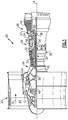
- FIG. 1 schematically illustrates a gas turbine engine 20.
- the gas turbine engine 20 is disclosed herein as a two-spool turbofan that generally incorporates a fan section 22, a compressor section 24, a combustor section 26 and a turbine section 28.
- Alternative engines might include an augmentor section (not shown) among other systems or features.
- the fan section 22 drives air along a bypass flowpath B in a bypass duct inwardly of a nacelle 80.
- the compressor section 24 receives air along a core flowpath C for compression and communication into the combustor section 26 then expansion through the turbine section 28.
- FIG. 1 schematically illustrates a gas turbine engine 20.
- the gas turbine engine 20 is disclosed herein as a two-spool turbofan that generally incorporates a fan section 22, a compressor section 24, a combustor section 26 and a turbine section 28.
- Alternative engines might include an augmentor section (not shown) among other systems or features.
- the fan section 22 drives air along a bypass flowpath B in a
- the engine 20 generally includes a low speed spool 30 and a high speed spool 32 mounted for rotation about an engine central longitudinal axis A relative to an engine static structure 36 via several bearing systems 38. It should be understood that various bearing systems 38 at various locations may alternatively or additionally be provided.
- the low pressure spool 30 generally includes an inner shaft 40 that interconnects a fan 42, a low pressure compressor 44 and a low pressure turbine 46.
- the inner shaft 40 is connected to the fan 42, directly or through a geared architecture 48 to drive the fan 42 at a lower speed than the low speed spool 30.
- the high pressure spool 32 includes an outer shaft 50 that interconnects a high pressure compressor 52 and high pressure turbine 54.
- a combustor 56 is arranged between the high pressure compressor 52 and the high pressure turbine 54.
- a mid-turbine frame 57 of the engine static structure 36 is arranged generally between the high pressure turbine 54 and the low pressure turbine 46.
- the mid-turbine frame 57 further supports bearing systems 38 in the turbine section 28.
- the inner shaft 40 and the outer shaft 50 are concentric and rotate via bearing systems 38 about the engine central longitudinal axis A which is collinear with their longitudinal axes.
- the core airflow is compressed by the low pressure compressor 44 then the high pressure compressor 52, mixed and burned with fuel in the combustor 56, then expanded over the high pressure turbine 54 and low pressure turbine 46.
- the mid-turbine frame 57 includes airfoils 59 which are in the core airflow path.
- the turbines 46, 54 rotationally drive the respective low speed spool 30 and high speed spool 32 in response to the expansion.
- the engine 20 in one example is a high-bypass geared aircraft engine.
- the engine 20 bypass ratio is greater than six (6), with an example embodiment being greater than ten (10)
- the geared architecture 48 is an epicyclic gear train, such as a planetary gear system or other gear system, with a gear reduction ratio of greater than 2.3 and the low pressure turbine 46 has a pressure ratio that is greater than 5.
- the engine 20 bypass ratio is greater than ten (10:1)
- the fan diameter is significantly larger than that of the low pressure compressor 44
- the low pressure turbine 46 has a pressure ratio that is greater than 5:1.
- Low pressure turbine 46 pressure ratio is pressure measured prior to inlet of low pressure turbine 46 as related to the pressure at the outlet of the low pressure turbine 46 prior to an exhaust nozzle.
- the geared architecture 48 may be an epicycle gear train, such as a planetary gear system or other gear system, with a gear reduction ratio of greater than 2.5:1. It should be understood, however, that the above parameters are only exemplary of one embodiment of a geared architecture engine and that the present invention is applicable to other gas turbine engines including direct drive turbofans.
- the fan section 22 of the engine 20 is designed for a particular flight condition -- typically cruise at about 0.8 Mach and about 35,000 feet (10668 m).
- "Low fan pressure ratio” is the pressure ratio across the fan blade alone, without a Fan Exit Guide Vane (“FEGV”) system.
- the low fan pressure ratio as disclosed herein according to one non-limiting embodiment is less than 1.45.
- Low corrected fan tip speed is the actual fan tip speed in ft/sec divided by an industry standard temperature correction of [(Tram °R) / (518.7 °R)] 0.5 .
- the "Low corrected fan tip speed” as disclosed herein according to one non-limiting embodiment is less than about 1150 ft / second (350 m/second).
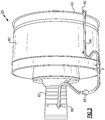
- Figure 2 shows the compressor section 52 having an inner wall 81, and an outer wall 82. These features may be part of a gas turbine engine generally as disclosed in Figure 1 .
- the compressor section is provided with a compressor stability bleed valve 94.
- This valve is under the control of a control 196 which selectively opens the bleed valve 94 during engine startup such that compressed air is dumped outwardly of the compressor section 52 into a chamber 96. This reduces the load on the compressor rotors as they begin to rotate.
- the compressor stability bleed valve 94 dumps air into the chamber 96, and thus, components 200, shown schematically, within the space 96 are exposed to this hot air.
- the control 196 also controls an anti-ice valve 88.
- the anti-ice valve 88 also includes a tap 86 for tapping compressed air. As would be understood by someone who works in this art, this compressed air would be hot.
- the tap 86 passes through the anti-ice valve 88, into a conduit 84, and then to a nozzle 90 associated with a lip 92 at an upstream end of the nacelle 80.
- the nozzle 90 would shoot air in opposed circumferential directions such that the lip 92 is provided with this hot air, should conditions indicate that there may be icing.
- the anti-ice valve 88 would not be left open at all times, as that would reduce the efficiency of the compressor.
- the anti-ice valve 88 is normally closed, however, a control will open the valve when conditions indicate icing.
- the anti-ice valve 88 has remained closed at startup, when the compressor stability bleed valves might open.
- an anti-ice valve may have been opened at startup, but only if ambient conditions dictated the use.
- the present control algorithm would ensure the anti-ice valve is opened at startup, without consideration of ambient conditions.
- the specific embodiment does include both a bleed valve 94, and the anti-ice valve 88, it is possible the anti-ice valve 88 could be utilized on its own within the scope of this disclosure.
- control 196 may open the anti-ice valve 88 at startup.
- the anti-ice valve 88 may be designed such that it is normally opened, and is left open at startup. In such an arrangement, the control 196 would be operable to close the valve 88 when conditions do not warrant the tapping of hot air for an anti-icing function.
- the present invention utilizes the anti-ice valve 88 to perform not only the anti-ice function, but also to provide a compressor stability bleed valve. This thus eliminates the need for plural bleed valves. Further, should the valve 88 fail, it is directing hot air to a less sensitive area than does bleed valve 94.
Landscapes
- Engineering & Computer Science (AREA)
- Chemical & Material Sciences (AREA)
- Combustion & Propulsion (AREA)
- Mechanical Engineering (AREA)
- General Engineering & Computer Science (AREA)
- Physics & Mathematics (AREA)
- Fluid Mechanics (AREA)
- Aviation & Aerospace Engineering (AREA)
- Control Of Turbines (AREA)
- Structures Of Non-Positive Displacement Pumps (AREA)
Claims (10)
- Moteur à turbine à gaz (20) comprenant :une section de compresseur (52) reçue à l'intérieur d'un logement interne (81), et il est prévu un logement externe (82) espacé radialement vers l'extérieur dudit logement interne (81), une nacelle (80) ;un système d'antigivrage de nacelle conçu pour exploiter l'air comprimé provenant de ladite section de compresseur (52) à travers une vanne d'antigivrage (88) et jusqu'à ladite nacelle (80) ; etune commande (196) ;caractérisé en ce que ladite commande (196) est conçue pour veiller à ce que ladite vanne d'antigivrage (88) est ouverte au démarrage du moteur à turbine à gaz (20) sans égard aux conditions environnementales pour les besoins de l'assistance de stabilité de compresseur.
- Moteur à turbine à gaz selon la revendication 1, dans lequel ladite vanne d'antigivrage (88) est laissée ouverte au démarrage et la commande (196) peut être utilisée pour fermer la vanne d'antigivrage (88) lorsque les conditions ne garantissent pas l'exploitation de l'air chaud pour la fonction d'antigivrage.
- Moteur à turbine à gaz selon la revendication 1 ou 2, dans lequel ledit système d'antigivrage comprend une buse (90) positionnée de manière adjacente à un bord amont (92) de ladite nacelle (80).
- Moteur à turbine à gaz selon une quelconque revendication précédente, dans lequel une vanne de prélèvement de stabilité de compresseur (94) est positionnée dans ledit logement intérieur (81) pour vider de manière sélective l'air qui a été au moins partiellement compressé et dans lequel ladite commande (196) est également conçue pour ouvrir ladite vanne de prélèvement (94) pendant un démarrage.
- Moteur à turbine à gaz selon une quelconque revendication précédente, dans lequel une soufflante (22) est incluse dans le moteur à turbine à gaz (20), et ladite soufflante (22) fournissant de l'air dans une conduite de dérivation à l'intérieur de ladite nacelle (80), et fournissant également de l'air dans ladite section de compresseur (52).
- Moteur à turbine à gaz selon la revendication 5, dans lequel un taux de dilution peut être décrit comme le volume d'air passant dans ladite conduite de dérivation par rapport au volume d'air passant dans ladite section de compresseur (52), et ledit taux de dilution étant supérieur à 6.
- Moteur à turbine à gaz selon la revendication 6, dans lequel ledit taux de dilution est supérieur à 10.
- Moteur à turbine à gaz selon l'une quelconque des revendications 5, 6 ou 7, dans lequel ladite soufflante (22) est commandée par une turbine (28) qui est incluse dans ledit moteur à turbine à gaz (20), et une démultiplication est positionnée entre ladite soufflante (22) et ladite turbine (28).
- Moteur à turbine à gaz selon la revendication 8, dans lequel un rapport d'engrenage de ladite démultiplication est supérieur à 2,3.
- Moteur à turbine à gaz selon la revendication 9, dans lequel ladite démultiplication est supérieure à 2,5.
Applications Claiming Priority (3)
| Application Number | Priority Date | Filing Date | Title |
|---|---|---|---|
| US201261706367P | 2012-09-27 | 2012-09-27 | |
| US13/731,133 US9879599B2 (en) | 2012-09-27 | 2012-12-31 | Nacelle anti-ice valve utilized as compressor stability bleed valve during starting |
| PCT/US2013/061367 WO2014052297A1 (fr) | 2012-09-27 | 2013-09-24 | Vanne d'antigivrage de nacelle servant de vanne de prélèvement de stabilité de compresseur pendant un démarrage |
Publications (3)
| Publication Number | Publication Date |
|---|---|
| EP2900957A1 EP2900957A1 (fr) | 2015-08-05 |
| EP2900957A4 EP2900957A4 (fr) | 2016-04-27 |
| EP2900957B1 true EP2900957B1 (fr) | 2019-11-20 |
Family
ID=50388902
Family Applications (1)
| Application Number | Title | Priority Date | Filing Date |
|---|---|---|---|
| EP13842277.9A Active EP2900957B1 (fr) | 2012-09-27 | 2013-09-24 | Vanne d'antigivrage de nacelle servant de vanne de prélèvement de stabilité de compresseur pendant un démarrage |
Country Status (3)
| Country | Link |
|---|---|
| US (1) | US9879599B2 (fr) |
| EP (1) | EP2900957B1 (fr) |
| WO (1) | WO2014052297A1 (fr) |
Families Citing this family (17)
| Publication number | Priority date | Publication date | Assignee | Title |
|---|---|---|---|---|
| US9869190B2 (en) | 2014-05-30 | 2018-01-16 | General Electric Company | Variable-pitch rotor with remote counterweights |
| GB201416928D0 (en) * | 2014-09-25 | 2014-11-12 | Rolls Royce Plc | A gas turbine and a method of washing a gas turbine engine |
| US10072510B2 (en) | 2014-11-21 | 2018-09-11 | General Electric Company | Variable pitch fan for gas turbine engine and method of assembling the same |
| CN104727945A (zh) * | 2015-01-30 | 2015-06-24 | 江苏中陆航星航空工业有限公司 | 一种飞机发动机进气道除冰系统 |
| EP3311277A4 (fr) * | 2015-06-18 | 2019-02-20 | Sikorsky Aircraft Corporation | Systèmes et procédés permettant d'effectuer le diagnostic de vannes de purge d'un turbomoteur |
| US10054052B2 (en) | 2015-07-07 | 2018-08-21 | United Technologies Corporation | Nacelle anti-ice system and method with equalized flow |
| US10100733B2 (en) | 2015-07-31 | 2018-10-16 | Ge Aviation Systems Llc | Turbine engine with anti-ice valve assembly, bleed air valve, and method of operating |
| US10100653B2 (en) | 2015-10-08 | 2018-10-16 | General Electric Company | Variable pitch fan blade retention system |
| US10578307B2 (en) * | 2015-10-09 | 2020-03-03 | Dresser-Rand Company | System and method for operating a gas turbine assembly including heating a reaction/oxidation chamber |
| US10823060B2 (en) * | 2015-12-18 | 2020-11-03 | Raytheon Technologies Corporation | Gas turbine engine with short inlet, acoustic treatment and anti-icing features |
| RU2666886C1 (ru) * | 2017-11-14 | 2018-09-12 | Акционерное общество "Объединенная двигателестроительная корпорация" (АО "ОДК") | Способ управления противообледенительной системой воздухозаборника газотурбинного двигателя самолета |
| GB201807840D0 (en) | 2018-05-15 | 2018-06-27 | Rolls Royce Plc | Gas turbine engine |
| EP3587876B1 (fr) | 2018-06-22 | 2022-03-02 | Microtecnica S.r.l. | Soupape d'arrêt de régulation de pression, son piston et méthodes correspondantes de fabrication |
| US11674435B2 (en) | 2021-06-29 | 2023-06-13 | General Electric Company | Levered counterweight feathering system |
| US11795964B2 (en) | 2021-07-16 | 2023-10-24 | General Electric Company | Levered counterweight feathering system |
| US11788465B2 (en) | 2022-01-19 | 2023-10-17 | General Electric Company | Bleed flow assembly for a gas turbine engine |
| US11808281B2 (en) | 2022-03-04 | 2023-11-07 | General Electric Company | Gas turbine engine with variable pitch inlet pre-swirl features |
Citations (1)
| Publication number | Priority date | Publication date | Assignee | Title |
|---|---|---|---|---|
| USB535928I5 (fr) * | 1974-12-23 | 1976-01-13 |
Family Cites Families (31)
| Publication number | Priority date | Publication date | Assignee | Title |
|---|---|---|---|---|
| US535928A (en) | 1895-03-19 | Pneumatic recoil-check for gun-carriages | ||
| US2747365A (en) * | 1953-07-03 | 1956-05-29 | Armstroug Siddeley Motors Ltd | Supply of hot air from a gas turbine engine for anti-icing or other purposes |
| US3057154A (en) * | 1959-07-07 | 1962-10-09 | Rolls Royce | De-icer system for a gas turbine engine |
| US3792584A (en) * | 1972-02-16 | 1974-02-19 | Boeing Co | Increased or variable bypass ratio engines |
| US4482114A (en) * | 1981-01-26 | 1984-11-13 | The Boeing Company | Integrated thermal anti-icing and environmental control system |
| US4463552A (en) * | 1981-12-14 | 1984-08-07 | United Technologies Corporation | Combined surge bleed and dust removal system for a fan-jet engine |
| US4738416A (en) | 1986-09-26 | 1988-04-19 | Quiet Nacelle Corporation | Nacelle anti-icing system |
| US4783026A (en) * | 1987-05-22 | 1988-11-08 | Avco Corporation | Anti-icing management system |
| US4831819A (en) | 1987-07-02 | 1989-05-23 | Avco Corporation | Anti-icing valve |
| US5261228A (en) * | 1992-06-25 | 1993-11-16 | General Electric Company | Apparatus for bleeding air |
| US6267328B1 (en) * | 1999-10-21 | 2001-07-31 | Rohr, Inc. | Hot air injection for swirling rotational anti-icing system |
| US6354538B1 (en) * | 1999-10-25 | 2002-03-12 | Rohr, Inc. | Passive control of hot air injection for swirling rotational type anti-icing system |
| US6688558B2 (en) * | 1999-11-23 | 2004-02-10 | The Boeing Company | Method and apparatus for aircraft inlet ice protection |
| US6371411B1 (en) * | 1999-11-23 | 2002-04-16 | The Boeing Company | Method and apparatus for aircraft inlet ice protection |
| US7131612B2 (en) | 2003-07-29 | 2006-11-07 | Pratt & Whitney Canada Corp. | Nacelle inlet lip anti-icing with engine oil |
| US8585538B2 (en) * | 2006-07-05 | 2013-11-19 | United Technologies Corporation | Coupling system for a star gear train in a gas turbine engine |
| US20100162683A1 (en) * | 2006-10-12 | 2010-07-01 | Grabowski Zbigniew M | Turbofan engine |
| US7874137B2 (en) | 2007-06-18 | 2011-01-25 | Honeywell International Inc. | Gas turbine engine anti-ice formation device and system |
| US20120124964A1 (en) | 2007-07-27 | 2012-05-24 | Hasel Karl L | Gas turbine engine with improved fuel efficiency |
| US9701415B2 (en) | 2007-08-23 | 2017-07-11 | United Technologies Corporation | Gas turbine engine with axial movable fan variable area nozzle |
| US20090108134A1 (en) * | 2007-10-25 | 2009-04-30 | General Electric Company | Icing protection system and method for enhancing heat transfer |
| US7900872B2 (en) | 2007-12-12 | 2011-03-08 | Spirit Aerosystems, Inc. | Nacelle inlet thermal anti-icing spray duct support system |
| FR2925878B1 (fr) | 2007-12-28 | 2010-04-23 | Airbus France | Ensemble propulsif d'aeronef comprenant des systemes de prelevement d'air chaud |
| US9010126B2 (en) * | 2008-02-20 | 2015-04-21 | United Technologies Corporation | Gas turbine engine with variable area fan nozzle bladder system |
| US7959109B2 (en) | 2008-07-02 | 2011-06-14 | The Boeing Company | Dual valve apparatus for aircraft engine ice protection and related methods |
| GB0922425D0 (en) * | 2009-12-23 | 2010-02-03 | Rolls Royce Plc | Bleed assembly for a gas turbine engine |
| US8869507B2 (en) * | 2010-01-13 | 2014-10-28 | United Technologies Corporation | Translatable cascade thrust reverser |
| US8347637B2 (en) * | 2010-05-25 | 2013-01-08 | United Technologies Corporation | Accessory gearbox with internal layshaft |
| US8397487B2 (en) | 2011-02-28 | 2013-03-19 | General Electric Company | Environmental control system supply precooler bypass |
| US8387950B2 (en) * | 2011-04-06 | 2013-03-05 | General Electric Company | Flow device and method and system using the flow device |
| US8967528B2 (en) * | 2012-01-24 | 2015-03-03 | The Boeing Company | Bleed air systems for use with aircrafts and related methods |
-
2012
- 2012-12-31 US US13/731,133 patent/US9879599B2/en active Active
-
2013
- 2013-09-24 WO PCT/US2013/061367 patent/WO2014052297A1/fr active Application Filing
- 2013-09-24 EP EP13842277.9A patent/EP2900957B1/fr active Active
Patent Citations (1)
| Publication number | Priority date | Publication date | Assignee | Title |
|---|---|---|---|---|
| USB535928I5 (fr) * | 1974-12-23 | 1976-01-13 |
Also Published As
| Publication number | Publication date |
|---|---|
| US20140245749A1 (en) | 2014-09-04 |
| EP2900957A4 (fr) | 2016-04-27 |
| US9879599B2 (en) | 2018-01-30 |
| WO2014052297A1 (fr) | 2014-04-03 |
| EP2900957A1 (fr) | 2015-08-05 |
Similar Documents
| Publication | Publication Date | Title |
|---|---|---|
| EP2900957B1 (fr) | Vanne d'antigivrage de nacelle servant de vanne de prélèvement de stabilité de compresseur pendant un démarrage | |
| EP3036416B1 (fr) | Moteur à turbine à gaz à engrenages de poussée élevée | |
| EP3808964B1 (fr) | Turboréacteur à engrenages avec système de réduction d'engrenage non épicyclique | |
| EP2809921B1 (fr) | Turbine à gaz dotée d'une aube guide d'entrée de compresseur positionnée pour le démarrage | |
| EP2949883B1 (fr) | Système de lubrification de moteur de turbine à gaz | |
| EP3584427B1 (fr) | Système à air de refroidissement refroidi avec de l'air à basse température pour compartiment de palier | |
| EP3690213B1 (fr) | Contrôle environnemental d'un aéronef | |
| EP2927433B1 (fr) | Contrôle actif de jeu pour moteur de turbine à gaz | |
| US20170074112A1 (en) | Active clearance control for gas turbine engine | |
| EP2809924B1 (fr) | Moteur à turbine à gaz avec tuyère de soufflante à section variable positionnée pour le démarrage | |
| EP3105438B1 (fr) | Collecteur de ventilation de nacelle | |
| EP2900995B1 (fr) | Moteur à turbine à gaz à engrenages avec une tuyère intégrée à section variable pour réduire le bruit | |
| EP3575574B1 (fr) | Gestion thermique d'un arbre de moteur à turbine à gaz | |
| EP3572645B1 (fr) | Refroidissement amélioré d'aube de turbine en aval pour un moteur à turbine à gaz | |
| EP3388637B1 (fr) | Chambre d'air de refroidissement pour joint d'air extérieur d'aube | |
| EP3388625B1 (fr) | Air de refroidissement refroidi vers un joint d'air extérieur d'aubes à travers une aube de stator | |
| EP2900978B1 (fr) | Compresseur avec structure de montage à crochet pour dispositif d'étanchéité avec revêtement superposé | |
| EP2904217B1 (fr) | Aube directrice et moteur à turbine à gaz associé | |
| EP2985425B1 (fr) | Système de dosage de fluide de refroidissement d'un moteur à turbine à gaz | |
| EP3604766B1 (fr) | Air de refroidissement refroidi à décharge de pression sélective | |
| EP3597870B1 (fr) | Turbine à gaz | |
| EP3358152B1 (fr) | Chambre de mélange externe pour moteur à turbine à gaz avec de l'air de refroidissement de turbine refroidi | |
| EP3181869A1 (fr) | Refroidissement de diamètre interne de compresseur | |
| EP3348812B1 (fr) | Air de refroidissement de moteur à turbine à gaz avec décharge d'air froid | |
| EP2955325B1 (fr) | Turboréacteur à engrenages à rotor à aubage intégral |
Legal Events
| Date | Code | Title | Description |
|---|---|---|---|
| PUAI | Public reference made under article 153(3) epc to a published international application that has entered the european phase |
Free format text: ORIGINAL CODE: 0009012 |
|
| 17P | Request for examination filed |
Effective date: 20150427 |
|
| AK | Designated contracting states |
Kind code of ref document: A1 Designated state(s): AL AT BE BG CH CY CZ DE DK EE ES FI FR GB GR HR HU IE IS IT LI LT LU LV MC MK MT NL NO PL PT RO RS SE SI SK SM TR |
|
| AX | Request for extension of the european patent |
Extension state: BA ME |
|
| DAX | Request for extension of the european patent (deleted) | ||
| RA4 | Supplementary search report drawn up and despatched (corrected) |
Effective date: 20160330 |
|
| RIC1 | Information provided on ipc code assigned before grant |
Ipc: F02K 3/06 20060101ALI20160322BHEP Ipc: F02C 7/04 20060101AFI20160322BHEP |
|
| RAP1 | Party data changed (applicant data changed or rights of an application transferred) |
Owner name: UNITED TECHNOLOGIES CORPORATION |
|
| STAA | Information on the status of an ep patent application or granted ep patent |
Free format text: STATUS: EXAMINATION IS IN PROGRESS |
|
| 17Q | First examination report despatched |
Effective date: 20180914 |
|
| GRAP | Despatch of communication of intention to grant a patent |
Free format text: ORIGINAL CODE: EPIDOSNIGR1 |
|
| STAA | Information on the status of an ep patent application or granted ep patent |
Free format text: STATUS: GRANT OF PATENT IS INTENDED |
|
| INTG | Intention to grant announced |
Effective date: 20190531 |
|
| GRAS | Grant fee paid |
Free format text: ORIGINAL CODE: EPIDOSNIGR3 |
|
| GRAA | (expected) grant |
Free format text: ORIGINAL CODE: 0009210 |
|
| STAA | Information on the status of an ep patent application or granted ep patent |
Free format text: STATUS: THE PATENT HAS BEEN GRANTED |
|
| AK | Designated contracting states |
Kind code of ref document: B1 Designated state(s): AL AT BE BG CH CY CZ DE DK EE ES FI FR GB GR HR HU IE IS IT LI LT LU LV MC MK MT NL NO PL PT RO RS SE SI SK SM TR |
|
| REG | Reference to a national code |
Ref country code: GB Ref legal event code: FG4D |
|
| REG | Reference to a national code |
Ref country code: CH Ref legal event code: EP |
|
| REG | Reference to a national code |
Ref country code: IE Ref legal event code: FG4D |
|
| REG | Reference to a national code |
Ref country code: DE Ref legal event code: R096 Ref document number: 602013063197 Country of ref document: DE |
|
| REG | Reference to a national code |
Ref country code: AT Ref legal event code: REF Ref document number: 1204462 Country of ref document: AT Kind code of ref document: T Effective date: 20191215 |
|
| REG | Reference to a national code |
Ref country code: NL Ref legal event code: MP Effective date: 20191120 |
|
| REG | Reference to a national code |
Ref country code: LT Ref legal event code: MG4D |
|
| PG25 | Lapsed in a contracting state [announced via postgrant information from national office to epo] |
Ref country code: NO Free format text: LAPSE BECAUSE OF FAILURE TO SUBMIT A TRANSLATION OF THE DESCRIPTION OR TO PAY THE FEE WITHIN THE PRESCRIBED TIME-LIMIT Effective date: 20200220 Ref country code: LT Free format text: LAPSE BECAUSE OF FAILURE TO SUBMIT A TRANSLATION OF THE DESCRIPTION OR TO PAY THE FEE WITHIN THE PRESCRIBED TIME-LIMIT Effective date: 20191120 Ref country code: GR Free format text: LAPSE BECAUSE OF FAILURE TO SUBMIT A TRANSLATION OF THE DESCRIPTION OR TO PAY THE FEE WITHIN THE PRESCRIBED TIME-LIMIT Effective date: 20200221 Ref country code: NL Free format text: LAPSE BECAUSE OF FAILURE TO SUBMIT A TRANSLATION OF THE DESCRIPTION OR TO PAY THE FEE WITHIN THE PRESCRIBED TIME-LIMIT Effective date: 20191120 Ref country code: SE Free format text: LAPSE BECAUSE OF FAILURE TO SUBMIT A TRANSLATION OF THE DESCRIPTION OR TO PAY THE FEE WITHIN THE PRESCRIBED TIME-LIMIT Effective date: 20191120 Ref country code: LV Free format text: LAPSE BECAUSE OF FAILURE TO SUBMIT A TRANSLATION OF THE DESCRIPTION OR TO PAY THE FEE WITHIN THE PRESCRIBED TIME-LIMIT Effective date: 20191120 Ref country code: BG Free format text: LAPSE BECAUSE OF FAILURE TO SUBMIT A TRANSLATION OF THE DESCRIPTION OR TO PAY THE FEE WITHIN THE PRESCRIBED TIME-LIMIT Effective date: 20200220 Ref country code: FI Free format text: LAPSE BECAUSE OF FAILURE TO SUBMIT A TRANSLATION OF THE DESCRIPTION OR TO PAY THE FEE WITHIN THE PRESCRIBED TIME-LIMIT Effective date: 20191120 |
|
| PG25 | Lapsed in a contracting state [announced via postgrant information from national office to epo] |
Ref country code: RS Free format text: LAPSE BECAUSE OF FAILURE TO SUBMIT A TRANSLATION OF THE DESCRIPTION OR TO PAY THE FEE WITHIN THE PRESCRIBED TIME-LIMIT Effective date: 20191120 Ref country code: IS Free format text: LAPSE BECAUSE OF FAILURE TO SUBMIT A TRANSLATION OF THE DESCRIPTION OR TO PAY THE FEE WITHIN THE PRESCRIBED TIME-LIMIT Effective date: 20200320 Ref country code: HR Free format text: LAPSE BECAUSE OF FAILURE TO SUBMIT A TRANSLATION OF THE DESCRIPTION OR TO PAY THE FEE WITHIN THE PRESCRIBED TIME-LIMIT Effective date: 20191120 |
|
| PG25 | Lapsed in a contracting state [announced via postgrant information from national office to epo] |
Ref country code: AL Free format text: LAPSE BECAUSE OF FAILURE TO SUBMIT A TRANSLATION OF THE DESCRIPTION OR TO PAY THE FEE WITHIN THE PRESCRIBED TIME-LIMIT Effective date: 20191120 |
|
| PG25 | Lapsed in a contracting state [announced via postgrant information from national office to epo] |
Ref country code: DK Free format text: LAPSE BECAUSE OF FAILURE TO SUBMIT A TRANSLATION OF THE DESCRIPTION OR TO PAY THE FEE WITHIN THE PRESCRIBED TIME-LIMIT Effective date: 20191120 Ref country code: EE Free format text: LAPSE BECAUSE OF FAILURE TO SUBMIT A TRANSLATION OF THE DESCRIPTION OR TO PAY THE FEE WITHIN THE PRESCRIBED TIME-LIMIT Effective date: 20191120 Ref country code: RO Free format text: LAPSE BECAUSE OF FAILURE TO SUBMIT A TRANSLATION OF THE DESCRIPTION OR TO PAY THE FEE WITHIN THE PRESCRIBED TIME-LIMIT Effective date: 20191120 Ref country code: PT Free format text: LAPSE BECAUSE OF FAILURE TO SUBMIT A TRANSLATION OF THE DESCRIPTION OR TO PAY THE FEE WITHIN THE PRESCRIBED TIME-LIMIT Effective date: 20200412 Ref country code: ES Free format text: LAPSE BECAUSE OF FAILURE TO SUBMIT A TRANSLATION OF THE DESCRIPTION OR TO PAY THE FEE WITHIN THE PRESCRIBED TIME-LIMIT Effective date: 20191120 Ref country code: CZ Free format text: LAPSE BECAUSE OF FAILURE TO SUBMIT A TRANSLATION OF THE DESCRIPTION OR TO PAY THE FEE WITHIN THE PRESCRIBED TIME-LIMIT Effective date: 20191120 |
|
| REG | Reference to a national code |
Ref country code: AT Ref legal event code: MK05 Ref document number: 1204462 Country of ref document: AT Kind code of ref document: T Effective date: 20191120 |
|
| REG | Reference to a national code |
Ref country code: DE Ref legal event code: R097 Ref document number: 602013063197 Country of ref document: DE |
|
| PG25 | Lapsed in a contracting state [announced via postgrant information from national office to epo] |
Ref country code: SK Free format text: LAPSE BECAUSE OF FAILURE TO SUBMIT A TRANSLATION OF THE DESCRIPTION OR TO PAY THE FEE WITHIN THE PRESCRIBED TIME-LIMIT Effective date: 20191120 Ref country code: SM Free format text: LAPSE BECAUSE OF FAILURE TO SUBMIT A TRANSLATION OF THE DESCRIPTION OR TO PAY THE FEE WITHIN THE PRESCRIBED TIME-LIMIT Effective date: 20191120 |
|
| PLBE | No opposition filed within time limit |
Free format text: ORIGINAL CODE: 0009261 |
|
| STAA | Information on the status of an ep patent application or granted ep patent |
Free format text: STATUS: NO OPPOSITION FILED WITHIN TIME LIMIT |
|
| 26N | No opposition filed |
Effective date: 20200821 |
|
| PG25 | Lapsed in a contracting state [announced via postgrant information from national office to epo] |
Ref country code: PL Free format text: LAPSE BECAUSE OF FAILURE TO SUBMIT A TRANSLATION OF THE DESCRIPTION OR TO PAY THE FEE WITHIN THE PRESCRIBED TIME-LIMIT Effective date: 20191120 Ref country code: SI Free format text: LAPSE BECAUSE OF FAILURE TO SUBMIT A TRANSLATION OF THE DESCRIPTION OR TO PAY THE FEE WITHIN THE PRESCRIBED TIME-LIMIT Effective date: 20191120 Ref country code: AT Free format text: LAPSE BECAUSE OF FAILURE TO SUBMIT A TRANSLATION OF THE DESCRIPTION OR TO PAY THE FEE WITHIN THE PRESCRIBED TIME-LIMIT Effective date: 20191120 |
|
| PG25 | Lapsed in a contracting state [announced via postgrant information from national office to epo] |
Ref country code: IT Free format text: LAPSE BECAUSE OF FAILURE TO SUBMIT A TRANSLATION OF THE DESCRIPTION OR TO PAY THE FEE WITHIN THE PRESCRIBED TIME-LIMIT Effective date: 20191120 |
|
| PG25 | Lapsed in a contracting state [announced via postgrant information from national office to epo] |
Ref country code: MC Free format text: LAPSE BECAUSE OF FAILURE TO SUBMIT A TRANSLATION OF THE DESCRIPTION OR TO PAY THE FEE WITHIN THE PRESCRIBED TIME-LIMIT Effective date: 20191120 |
|
| REG | Reference to a national code |
Ref country code: CH Ref legal event code: PL |
|
| REG | Reference to a national code |
Ref country code: BE Ref legal event code: MM Effective date: 20200930 |
|
| PG25 | Lapsed in a contracting state [announced via postgrant information from national office to epo] |
Ref country code: LU Free format text: LAPSE BECAUSE OF NON-PAYMENT OF DUE FEES Effective date: 20200924 |
|
| PG25 | Lapsed in a contracting state [announced via postgrant information from national office to epo] |
Ref country code: LI Free format text: LAPSE BECAUSE OF NON-PAYMENT OF DUE FEES Effective date: 20200930 Ref country code: IE Free format text: LAPSE BECAUSE OF NON-PAYMENT OF DUE FEES Effective date: 20200924 Ref country code: CH Free format text: LAPSE BECAUSE OF NON-PAYMENT OF DUE FEES Effective date: 20200930 Ref country code: BE Free format text: LAPSE BECAUSE OF NON-PAYMENT OF DUE FEES Effective date: 20200930 |
|
| PG25 | Lapsed in a contracting state [announced via postgrant information from national office to epo] |
Ref country code: TR Free format text: LAPSE BECAUSE OF FAILURE TO SUBMIT A TRANSLATION OF THE DESCRIPTION OR TO PAY THE FEE WITHIN THE PRESCRIBED TIME-LIMIT Effective date: 20191120 Ref country code: MT Free format text: LAPSE BECAUSE OF FAILURE TO SUBMIT A TRANSLATION OF THE DESCRIPTION OR TO PAY THE FEE WITHIN THE PRESCRIBED TIME-LIMIT Effective date: 20191120 Ref country code: CY Free format text: LAPSE BECAUSE OF FAILURE TO SUBMIT A TRANSLATION OF THE DESCRIPTION OR TO PAY THE FEE WITHIN THE PRESCRIBED TIME-LIMIT Effective date: 20191120 |
|
| PG25 | Lapsed in a contracting state [announced via postgrant information from national office to epo] |
Ref country code: MK Free format text: LAPSE BECAUSE OF FAILURE TO SUBMIT A TRANSLATION OF THE DESCRIPTION OR TO PAY THE FEE WITHIN THE PRESCRIBED TIME-LIMIT Effective date: 20191120 |
|
| REG | Reference to a national code |
Ref country code: DE Ref legal event code: R081 Ref document number: 602013063197 Country of ref document: DE Owner name: RAYTHEON TECHNOLOGIES CORPORATION (N.D.GES.D.S, US Free format text: FORMER OWNER: UNITED TECHNOLOGIES CORPORATION, FARMINGTON, CONN., US |
|
| P01 | Opt-out of the competence of the unified patent court (upc) registered |
Effective date: 20230520 |
|
| PGFP | Annual fee paid to national office [announced via postgrant information from national office to epo] |
Ref country code: GB Payment date: 20230823 Year of fee payment: 11 |
|
| PGFP | Annual fee paid to national office [announced via postgrant information from national office to epo] |
Ref country code: FR Payment date: 20230822 Year of fee payment: 11 Ref country code: DE Payment date: 20230822 Year of fee payment: 11 |