EP2900572B1 - Single serve capsule comprising a filter element connected thereto by sealing - Google Patents
Single serve capsule comprising a filter element connected thereto by sealing Download PDFInfo
- Publication number
- EP2900572B1 EP2900572B1 EP13771121.4A EP13771121A EP2900572B1 EP 2900572 B1 EP2900572 B1 EP 2900572B1 EP 13771121 A EP13771121 A EP 13771121A EP 2900572 B1 EP2900572 B1 EP 2900572B1
- Authority
- EP
- European Patent Office
- Prior art keywords
- filter element
- single serve
- serve capsule
- capsule
- diameter
- Prior art date
- Legal status (The legal status is an assumption and is not a legal conclusion. Google has not performed a legal analysis and makes no representation as to the accuracy of the status listed.)
- Active
Links
- 239000002775 capsule Substances 0.000 title claims description 56
- 238000007789 sealing Methods 0.000 title claims description 17
- 235000013361 beverage Nutrition 0.000 claims description 18
- 238000004519 manufacturing process Methods 0.000 description 10
- 239000011324 bead Substances 0.000 description 8
- 235000013353 coffee beverage Nutrition 0.000 description 8
- 238000002360 preparation method Methods 0.000 description 8
- 239000000758 substrate Substances 0.000 description 8
- 235000016213 coffee Nutrition 0.000 description 7
- 239000000835 fiber Substances 0.000 description 5
- 241001122767 Theaceae Species 0.000 description 4
- 235000015114 espresso Nutrition 0.000 description 4
- 239000004744 fabric Substances 0.000 description 4
- 230000007704 transition Effects 0.000 description 4
- 239000007788 liquid Substances 0.000 description 3
- 239000006260 foam Substances 0.000 description 2
- 238000002347 injection Methods 0.000 description 2
- 239000007924 injection Substances 0.000 description 2
- 238000001746 injection moulding Methods 0.000 description 2
- 239000004033 plastic Substances 0.000 description 2
- 239000000843 powder Substances 0.000 description 2
- XLYOFNOQVPJJNP-UHFFFAOYSA-N water Substances O XLYOFNOQVPJJNP-UHFFFAOYSA-N 0.000 description 2
- 238000003466 welding Methods 0.000 description 2
- 238000004873 anchoring Methods 0.000 description 1
- 239000003795 chemical substances by application Substances 0.000 description 1
- 238000010276 construction Methods 0.000 description 1
- 239000000284 extract Substances 0.000 description 1
- 238000005187 foaming Methods 0.000 description 1
- 239000011888 foil Substances 0.000 description 1
- 238000003780 insertion Methods 0.000 description 1
- 230000037431 insertion Effects 0.000 description 1
- 230000002093 peripheral effect Effects 0.000 description 1
- 239000002985 plastic film Substances 0.000 description 1
- 229920006255 plastic film Polymers 0.000 description 1
- 238000007639 printing Methods 0.000 description 1
- 239000000126 substance Substances 0.000 description 1
- 238000002604 ultrasonography Methods 0.000 description 1
- 239000000341 volatile oil Substances 0.000 description 1
Images

Classifications
-
- B—PERFORMING OPERATIONS; TRANSPORTING
- B65—CONVEYING; PACKING; STORING; HANDLING THIN OR FILAMENTARY MATERIAL
- B65D—CONTAINERS FOR STORAGE OR TRANSPORT OF ARTICLES OR MATERIALS, e.g. BAGS, BARRELS, BOTTLES, BOXES, CANS, CARTONS, CRATES, DRUMS, JARS, TANKS, HOPPERS, FORWARDING CONTAINERS; ACCESSORIES, CLOSURES, OR FITTINGS THEREFOR; PACKAGING ELEMENTS; PACKAGES
- B65D85/00—Containers, packaging elements or packages, specially adapted for particular articles or materials
- B65D85/70—Containers, packaging elements or packages, specially adapted for particular articles or materials for materials not otherwise provided for
- B65D85/804—Disposable containers or packages with contents which are mixed, infused or dissolved in situ, i.e. without having been previously removed from the package
- B65D85/8043—Packages adapted to allow liquid to pass through the contents
- B65D85/8061—Filters
-
- B—PERFORMING OPERATIONS; TRANSPORTING
- B65—CONVEYING; PACKING; STORING; HANDLING THIN OR FILAMENTARY MATERIAL
- B65D—CONTAINERS FOR STORAGE OR TRANSPORT OF ARTICLES OR MATERIALS, e.g. BAGS, BARRELS, BOTTLES, BOXES, CANS, CARTONS, CRATES, DRUMS, JARS, TANKS, HOPPERS, FORWARDING CONTAINERS; ACCESSORIES, CLOSURES, OR FITTINGS THEREFOR; PACKAGING ELEMENTS; PACKAGES
- B65D85/00—Containers, packaging elements or packages, specially adapted for particular articles or materials
- B65D85/70—Containers, packaging elements or packages, specially adapted for particular articles or materials for materials not otherwise provided for
- B65D85/804—Disposable containers or packages with contents which are mixed, infused or dissolved in situ, i.e. without having been previously removed from the package
Definitions
- the present invention relates to a portion capsule for the manufacture of a drink having a side wall and a bottom, which together define a space, wherein a filter element is sealed to the bottom within the space.
- Such portion capsules are known from the prior art and are used for example for the production of coffee or tea or coffee-like beverages such as espresso.
- Coffee or tea or coffee-like beverages such as espresso.
- in the printing pens EP 1 792 850 B1 .
- US 2012/0070551 A1 and US 2003/0172813 A1 Portion capsules for coffee and espresso preparation revealed.
- the portion capsules are preferably frusto-conical or cylindrical in shape and are produced, for example, from a thermoformed plastic film or by plastic injection molding. They usually have a side wall with a peripheral flange, an open filling side for a beverage substrate to be extracted and / or dissolved beverage substrate and a capsule bottom, wherein between the beverage substrate and the capsule bottom is supported against the capsule bottom filter element. After insertion and sealing of the filter element to the portion capsule bottom and the filling of the beverage substrate, the portion capsule is closed with a lid film, which is sealed or glued, for example, on the flange.
- the portion capsule is introduced into a brewing chamber of a preparation device. Before, after or during the introduction of the portion capsule into the brewing chamber, the portion capsule is preferably opened on its bottom side, and after the brewing chamber has been sealed, the filling side of the portion capsule closed with a closing foil is pierced by piercing means. Subsequently, preparation liquid, preferably hot water, is conveyed under pressure into the portion capsule. The preparation liquid flows through the beverage substrate and extracts and / or dissolves the substances required for the beverage production from the beverage substrate. For the preparation of an espresso, for example, a brewing water pressure of up to 20 bar acts on the coffee powder to extract the essential oils.
- the portion capsules according to the prior art have the disadvantage that the beverage produced has comparatively much foam on its surface.
- the filter element is disc-shaped and has a circular cross-section.
- the sealed seam which connects the filter element to the bottom of the portion capsule in a material-tight manner, is preferably attached by ultrasonic welding.
- the filter element is liquid impermeable after sealing in the region of the sealing seam.
- the inner diameter of the sealed seam is 67 - 77% of the diameter of the filter element.
- the width of the sealed seam is 1 - 1.5 millimeters.
- the bottom of the portion capsule has a substantially planar portion which is circular in shape and whose outer diameter is 84-94% of the diameter of the filter element.
- the outer circumference of the flat portion is preferably followed by a bead, through which the flat portion is arranged slightly spaced from a possible display.
- the bead also forms the transition between the flat bottom and the side wall and gives the portion capsule stability.
- the filter element extends into the region of the bead and covers it at least partially without touching it.
- the bottom has a recess which is so large that substantially no pressure loss is produced by the outflow / throughflow of the beverage through this recess.
- This recess is preferably already in the Capsule bottom incorporated before the filter element is sealed to the capsule bottom.
- the recess is preferably closed before the preparation process with a film or the like, which can be removed or pierced by a piercing.
- the diameter of the filter element is smaller, in particular 1 - 5% smaller than the inner dimension of the portion capsule at ground level.
- the filter element has a felt structure.
- this is a needled felt structure.
- the filter element consists of at least one felt structure and a support structure, in particular a fabric structure, wherein particularly preferably the felt structure makes up at least a portion of the volume of the support structure.
- the felt structure extends over the entire cross section of the support structure, but more preferably over only a portion of the height.
- the felt structure is positively, positively and / or materially connected to the support structure.
- the filter element has two or more felt structures, which are preferably separated from each other by the support structure. The thickness of the two felt structures may be the same or different.
- a felt structure facing the powder or tea is thinner than the felt structure facing the capsule bottom, or vice versa.
- the surface of the felt structure is treated, for example, heat-treated, for example, to fix loose fibers.
- the filter element having a felt structure is merely inserted into the capsule, in particular on its bottom.
- the filter element can also be connected to the capsule, in particular its bottom, in particular materially bonded. When perforating the perforating agent can penetrate into this filter element.
- a plurality of filter elements, which have one or more felt structures and a carrier structure are arranged one above the other in the capsule and possibly joined together.
- a filter element having a support structure, in particular a fabric structure, and a felt structure is produced, for example, by providing a fabric structure consisting of longitudinal and transverse threads.
- a felt in particular a needle felt
- fiber units are preferably selected from 0.8 to 7 dtex.
- the connection of the individual fibers together to form a felt and / or its anchoring in the support structure preferably takes place through the production process of needling.
- needles are inserted with reverse barbs in the submitted fiber package at high speed and pulled out again. The barbs cause the fibers to overflow a variety of resulting loops entwined with each other and / or with the carrier fabric.
- the support element comprising one or more felt structures preferably comprises a mass occupancy (also referred to as grammage or basis weight) between 100 and 800 grams per square meter, more preferably between 200 and 650 grams per square meter, and most preferably substantially 150-250 grams per square meter for the production of tea and 600 - 700 grams per square meter for the production of coffee, espresso or the like.
- the filter element or the fleece preferably has a thickness of between 0.8 and 3.3 millimeters, more preferably between 1.1 and 3.0 millimeters and most preferably 1.2-1.4 millimeters for the production of tea and 2 , 6 - 3.0 millimeters for the production of coffee.
- the side wall and the bottom are an injection molded part.
- the side wall and the bottom are integrally provided.
- an energy generator is provided at the bottom of the portion capsule.
- This energy generator can be annular, rectangular, qudratisch, oval or have any other closed shape.
- the energy generator can be provided continuously or intermittently.
- the energy generator is provided integrally with the bottom and is produced together with the same during injection molding.
- the cross section of the energy generator is triangular, rectangular, square, circular or oval. The cross section may also have any other shape, as long as the energy generator protrudes from the surface.
- the energy generator is preferably provided on the surface of the floor which faces the space in which the beverage substrate to be extracted and / or dissolved is located.
- FIG. 1 shows the portion capsule 1 according to the invention, which is designed in the present case substantially frusto-conical.
- the portion capsule 1 has a circumferential side wall 1.2 and a bottom portion 1.1.
- the side wall 1.2 and the bottom area 1.1 span a space 1.7 in which there is a filter element 2, which in the present case has a felt structure.
- the filter element 2 is sealed by means of the tool 3, which has at its lower end sealing surfaces 3.1, to the bottom 1.1 of the portion capsule 1 to form a sealed seam 7.
- the portion capsule 1 is at least partially held in a counter holder 6.
- the bottom 1.1 of the portion capsule has a circular planar portion, at the outer end of an annular bead surrounds 1.3, which simultaneously represents the transition region 5 between the bottom and the side wall.
- a recess 1.6 here a circular recess, provided, which is preferably so large that when flowing out of the beverage produced from the portion capsule no appreciable pressure loss arises and / or that the beverage produced is not vortexed.
- the weld is provided annularly and that the outer diameter of the sealed seam L2 75 - 85%, here 70.6%, of the diameter L3 of the filter element.
- the seal seam is produced in the production of the beverage, especially in the production of coffee, no appreciable foam.
- the inner diameter L1 of the sealing seam 67-77%, here 72.5%, of the diameter of the filter element.
- the width of the sealed seam is 1.5 millimeters.
- Transverse flows in the felt structure are preferably at least limited in the region of the weld seam.
- the outer diameter of the filter element is, furthermore Favor t, provided greater than the outer diameter of the flat portion of the filter bottom.
- the outer diameter L4 of the flat portion of the capsule bottom 84 - 94%, here 90%, of the diameter L3 of the filter element.
- the filter element 2 consequently protrudes into the region of the bead without touching the bottom of the bead.
- the outer diameter L3 of the filter element is smaller than the diameter of the portion capsule in the region of the bottom.
- the sealing seam is provided concentrically to the recess 1.6 in the capsule bottom.
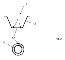
- the bottom 1.1 and the side wall 1.2 are preferably made as an injection molded part, preferably made of plastic. Furthermore, the bottom has an energy tanner 8, which is provided in the present case as an annular elevation here with a triangular cross-section.
- the energy generator can also have a different cross-section and also need not be provided continuously. With the energy generator, a linear sealing seam between the filter element and the bottom of the capsule succeeds.
- the energy generator is provided on the space 1.7 facing the surface of the bottom 1.1. In the lower illustration, the side wall 1.2 has been omitted for the sake of clarity.
Landscapes
- Engineering & Computer Science (AREA)
- Mechanical Engineering (AREA)
- Apparatus For Making Beverages (AREA)
- Packages (AREA)
- Packging For Living Organisms, Food Or Medicinal Products That Are Sensitive To Environmental Conditiond (AREA)
- Filtering Materials (AREA)
- Filtering Of Dispersed Particles In Gases (AREA)
- Distillation Of Fermentation Liquor, Processing Of Alcohols, Vinegar And Beer (AREA)
- Non-Alcoholic Beverages (AREA)
Description
Die vorliegende Erfindung betrifft eine Portionskapsel für die Herstellung eines Getränks mit einer Seitenwand und einem Boden, die gemeinsam einen Raum definieren, wobei innerhalb des Raums ein Filterelement an den Boden gesiegelt ist.The present invention relates to a portion capsule for the manufacture of a drink having a side wall and a bottom, which together define a space, wherein a filter element is sealed to the bottom within the space.
Derartige Portionskapseln sind aus dem Stand der Technik bekannt und werden beispielsweise zur Herstellung von Kaffee oder Tee oder kaffeeartigen Getränken wie Espresso eingesetzt. Beispielsweise sind in den Druckschiften
Die Portionskapseln sind bevorzugt kegelstumpfförmig oder zylindrisch geformt und werden beispielsweise aus einer tiefgezogenen Kunststofffolie oder im Kunststoffspritzverfahren hergestellt. Sie haben üblicherweise eine Seitenwand mit einem umlaufenden Flansch, eine offene Einfüllseite für ein zur Getränkeherstellung zu extrahierendes und/oder aufzulösendes Getränkesubstrat und einen Kapselboden, wobei zwischen dem Getränkesubstrat und dem Kapselboden ein sich gegen den Kapselboden abstützendes Filterelement angeordnet ist. Nach dem Einführen und Siegeln des Filterelementes an den Portionskapselboden und dem Einfüllen des Getränkesubstrates wird die Portionskapsel mit einer Deckelfolie verschlossen, die beispielsweise auf den Flansch aufgesiegelt oder aufgeklebt wird.The portion capsules are preferably frusto-conical or cylindrical in shape and are produced, for example, from a thermoformed plastic film or by plastic injection molding. They usually have a side wall with a peripheral flange, an open filling side for a beverage substrate to be extracted and / or dissolved beverage substrate and a capsule bottom, wherein between the beverage substrate and the capsule bottom is supported against the capsule bottom filter element. After insertion and sealing of the filter element to the portion capsule bottom and the filling of the beverage substrate, the portion capsule is closed with a lid film, which is sealed or glued, for example, on the flange.
Für die Zubereitung eines Kaffeegetränkes wird die Portionskapsel in eine Brühkammer eines Zubereitungsgerätes eingebracht. Vor, nach oder während des Einführens der Portionskapsel in die Brühkammer wird die Portionskapsel bevorzugt auf ihrer Bodenseite geöffnet und nach dem Abdichten der Brühkammer wird die mit einer Verschlussfolie verschlossene Einfüllseite der Portionskapsel mittels Einstechmitteln angestochen. Anschließend wird Zubereitungsflüssigkeit, vorzugsweise heißes Wasser, unter Druck in die Portionskapsel gefördert. Die Zubereitungsflüssigkeit durchströmt das Getränkesubstrat und extrahiert und/oder löst die für die Getränkeherstellung benötigten Stoffe aus dem Getränkesubstrat. Für die Zubereitung eines Espresso wirkt zum Extrahieren der ätherischen Öle beispielsweise ein Brühwasserdruck von bis zu 20 bar auf das Kaffepulver. Die Portionskapseln gemäß dem Stand der Technik haben jedoch den Nachteil, dass das hergestellte Getränk an seiner Oberfläche vergleichsweise viel Schaum aufweist.For the preparation of a coffee beverage, the portion capsule is introduced into a brewing chamber of a preparation device. Before, after or during the introduction of the portion capsule into the brewing chamber, the portion capsule is preferably opened on its bottom side, and after the brewing chamber has been sealed, the filling side of the portion capsule closed with a closing foil is pierced by piercing means. Subsequently, preparation liquid, preferably hot water, is conveyed under pressure into the portion capsule. The preparation liquid flows through the beverage substrate and extracts and / or dissolves the substances required for the beverage production from the beverage substrate. For the preparation of an espresso, for example, a brewing water pressure of up to 20 bar acts on the coffee powder to extract the essential oils. The portion capsules according to the prior art, however, have the disadvantage that the beverage produced has comparatively much foam on its surface.
Es war deshalb die Aufgabe der vorliegenden Erfindung, eine Portionskapsel zur Verfügung zu stellen, die die Nachteile des Standes der Technik nicht aufweist.It was therefore the object of the present invention to provide a portion capsule to provide that does not have the disadvantages of the prior art.
Gelöst wird die Aufgabe mit einer Portionskapsel für die Herstellung eines Getränks gemäß Anspruch 1.The object is achieved with a portion capsule for the preparation of a beverage according to
Die zu diesem Gegenstand der vorliegenden Erfindung gemachten Ausführungen gelten für die anderen Gegenstände der vorliegenden Erfindung gleichermaßen und umgekehrt.The statements made on this subject of the present invention apply equally to the other objects of the present invention and vice versa.
Es wurde nun überraschenderweise gefunden, dass eine kreisförmige Siegelnaht, deren äußerer Durchmesser 75 - 85 % des Durchmessers des Filterelementes beträgt, zumindest zu einer sehr geringen Schaumbildung führt.It has now surprisingly been found that a circular sealing seam, whose outer diameter is 75-85% of the diameter of the filter element, leads to at least very little foaming.
Das Filterelement ist scheibenförmig vorgesehen und weist einen kreisförmigen Querschnitt auf. Die Siegelnaht, die das Filterelement mit dem Boden der Portionskapsel stoffschlüssig verbindet, wird vorzugsweise durch Ultraschallschweißen angebracht. Vorzugsweise ist das Filterelement nach dem Siegeln im Bereich der Siegelnaht flüssigkeitsundurchlässig.The filter element is disc-shaped and has a circular cross-section. The sealed seam, which connects the filter element to the bottom of the portion capsule in a material-tight manner, is preferably attached by ultrasonic welding. Preferably, the filter element is liquid impermeable after sealing in the region of the sealing seam.
Der innere Durchmesser der Siegelnaht beträgt 67 - 77 % des Durchmessers des Filterelementes.The inner diameter of the sealed seam is 67 - 77% of the diameter of the filter element.
In einer bevorzugten Ausführungsform beträgt die Breite der Siegelnaht 1 - 1,5 Millimeter. Vorzugsweise weist der Boden der Portionskapsel einen im Wesentlichen ebenen Abschnitt auf, der kreisförmig gestaltet ist und dessen äußerer Durchmesser 84 - 94 % des Durchmessers des Filterelementes beträgt. An den äußeren Umfang des ebenen Abschnitts schließt sich vorzugsweise eine Sicke an, durch die der ebene Abschnitt etwas beabstandet von einer möglichen Auslage angeordnet ist. Die Sicke bildet außerdem den Übergang zwischen dem ebenen Boden und der Seitenwand und verleiht der Portionskapsel Stabilität. Vorzugsweise erstreckt sich das Filterelement bis in den Bereich der Sicke und überdeckt diese zumindest teilweise, ohne sie zu berühren.In a preferred embodiment, the width of the sealed seam is 1 - 1.5 millimeters. Preferably, the bottom of the portion capsule has a substantially planar portion which is circular in shape and whose outer diameter is 84-94% of the diameter of the filter element. The outer circumference of the flat portion is preferably followed by a bead, through which the flat portion is arranged slightly spaced from a possible display. The bead also forms the transition between the flat bottom and the side wall and gives the portion capsule stability. Preferably, the filter element extends into the region of the bead and covers it at least partially without touching it.
Gemäß einer bevorzugten Ausführungsform weist der Boden eine Ausnehmung auf, die so groß ist, dass beim Ausströmen/Durchströmen des Getränks durch diese Ausnehmung im Wesentlichen kein Druckverlust entsteht. Diese Ausnehmung ist vorzugsweise bereits in den Kapselboden eingearbeitet, bevor das Filterelement an den Kapselboden gesiegelt wird. Die Ausnehmung ist vor dem Zubereitungsvorgang vorzugsweise mit einer Folie oder dergleichen verschlossen, die abgezogen oder von einem Aufstechorgan durchstochen werden kann.According to a preferred embodiment, the bottom has a recess which is so large that substantially no pressure loss is produced by the outflow / throughflow of the beverage through this recess. This recess is preferably already in the Capsule bottom incorporated before the filter element is sealed to the capsule bottom. The recess is preferably closed before the preparation process with a film or the like, which can be removed or pierced by a piercing.
Vorzugsweise ist der Durchmesser des Filterelementes kleiner, insbesondere 1 - 5 % kleiner, als die Innenabmessung der Portionskapsel in Bodenhöhe.Preferably, the diameter of the filter element is smaller, in particular 1 - 5% smaller than the inner dimension of the portion capsule at ground level.
Vorzugsweise weist das Filterelement eine Filzstruktur auf. Insbesondere handelt es sich dabei um eine Nadelfilzstruktur. Vorzugsweise besteht das Filterelement aus mindestens einer Filzstruktur und einer Trägerstruktur, insbesondere einer Gewebestruktur, wobei besonders bevorzugt die Filzstruktur zumindest einen Teilabschnitt des Volumens der Trägerstruktur ausmacht. Vorzugsweise erstreckt sich die Filzstruktur über den gesamten Querschnitt der Trägerstruktur, besonders bevorzugt aber nur über einen Teilbereich der Höhe. Vorzugsweise ist die Filzstruktur form-, kraft- und/oder stoffschlüssig mit der Trägerstruktur verbunden. Vorzugsweise weist das Filterelement zwei oder mehr Filzstrukturen auf, die durch die Trägerstruktur vorzugsweise voneinander getrennt sind. Die Dicke der beiden Filzstrukturen kann gleich oder unterschiedlich sein. Vorzugsweise ist eine dem Pulver oder Tee zugewandte Filzstruktur dünner als die dem Kapselboden zugewandte Filzstruktur oder umgekehrt. Vorzugsweise wird die Oberfläche der Filzstruktur behandelt, beispielsweise wärmebehandelt, um beispielsweise lose Fasern zu fixieren. Vorzugsweise wird das eine Filzstruktur aufweisende Filterelement lediglich in die Kapsel, insbesondere auf deren Boden, eingelegt. Das Filterelement kann aber auch mit der Kapsel, insbesondere deren Boden, insbesondere stoffschlüssig, verbunden werden. Beim Perforieren kann das Perforationsmittel in dieses Filterelement eindringen. Vorzugsweise werden mehrere Filterelemente, die eine oder mehrere Filzstrukturen und eine Trägerstruktur aufweisen, in der Kapsel übereinander angeordnet und ggf. miteinander verbunden.Preferably, the filter element has a felt structure. In particular, this is a needled felt structure. Preferably, the filter element consists of at least one felt structure and a support structure, in particular a fabric structure, wherein particularly preferably the felt structure makes up at least a portion of the volume of the support structure. Preferably, the felt structure extends over the entire cross section of the support structure, but more preferably over only a portion of the height. Preferably, the felt structure is positively, positively and / or materially connected to the support structure. Preferably, the filter element has two or more felt structures, which are preferably separated from each other by the support structure. The thickness of the two felt structures may be the same or different. Preferably, a felt structure facing the powder or tea is thinner than the felt structure facing the capsule bottom, or vice versa. Preferably, the surface of the felt structure is treated, for example, heat-treated, for example, to fix loose fibers. Preferably, the filter element having a felt structure is merely inserted into the capsule, in particular on its bottom. However, the filter element can also be connected to the capsule, in particular its bottom, in particular materially bonded. When perforating the perforating agent can penetrate into this filter element. Preferably, a plurality of filter elements, which have one or more felt structures and a carrier structure, are arranged one above the other in the capsule and possibly joined together.
Ein eine Trägerstruktur, insbesondere eine Gewebestruktur, und eine Filzstruktur aufweisendes Filterelement wird beispielsweise dadurch hergestellt, dass eine Gewebestruktur bestehend aus Längs- und Querfäden zur Verfügung gestellt wird. Für die Konstruktion eines Filzes, insbesondere eines Nadelfilzes, werden vorzugsweise Fasereinheiten ausgewählt von 0.8 - 7 dtex. Die Verbindung der Einzelfasern miteinander zu einem Filz und/oder dessen Verankerung in der Trägerstruktur findet vorzugsweise durch den Produktionsprozess des Vernadelns statt. Dabei werden Nadeln mit umgekehrten Widerhaken in das vorgelegte Faserpaket mit hoher Geschwindigkeit eingestochen und wieder herausgezogen. Durch die Widerhaken werden die Fasern über eine Vielzahl entstehender Schlaufen miteinander und/oder mit dem Trägergewebe verschlungen.A filter element having a support structure, in particular a fabric structure, and a felt structure is produced, for example, by providing a fabric structure consisting of longitudinal and transverse threads. For the construction of a felt, in particular a needle felt, fiber units are preferably selected from 0.8 to 7 dtex. The connection of the individual fibers together to form a felt and / or its anchoring in the support structure preferably takes place through the production process of needling. In this case, needles are inserted with reverse barbs in the submitted fiber package at high speed and pulled out again. The barbs cause the fibers to overflow a variety of resulting loops entwined with each other and / or with the carrier fabric.
Das Trägerelement aufweisend eine oder mehrere Filzstrukturen umfasst bevorzugt eine Massenbelegung (auch als Grammatur oder Flächengewicht bezeichnet) zwischen 100 und 800 Gramm pro Quadratmeter, besonders bevorzugt zwischen 200 und 650 Gramm pro Quadratmeter und ganz besonders bevorzugt von im Wesentlichen 150 - 250 Gramm pro Quadratmeter für die Herstellung von Tee und 600 - 700 Gramm pro Quadratmeter für die Herstellung von Kaffee, Espresso oder dergleichen. Das Filterelement bzw. das Vlies weist bevorzugt eine Dicke zwischen 0,8 und 3,3 Millimetern, besonders bevorzugt zwischen 1,1 und 3,0 Millimetern und ganz besonders bevorzugt 1,2 - 1,4 Millimetern für die Herstellung von Tee und 2,6 - 3,0 Millimetern für die Herstellung von Kaffee auf.The support element comprising one or more felt structures preferably comprises a mass occupancy (also referred to as grammage or basis weight) between 100 and 800 grams per square meter, more preferably between 200 and 650 grams per square meter, and most preferably substantially 150-250 grams per square meter for the production of tea and 600 - 700 grams per square meter for the production of coffee, espresso or the like. The filter element or the fleece preferably has a thickness of between 0.8 and 3.3 millimeters, more preferably between 1.1 and 3.0 millimeters and most preferably 1.2-1.4 millimeters for the production of tea and 2 , 6 - 3.0 millimeters for the production of coffee.
Gemäß einem weiteren erfindungsgemäßen oder bevorzugten Gegenstand der vorliegenden Erfindung sind die Seitenwand und der Boden ein Spritzgussteil.According to a further inventive or preferred subject matter of the present invention, the side wall and the bottom are an injection molded part.
Die zu diesem Gegenstand der vorliegenden Erfindung gemachte Offenbarung gilt für die anderen Gegenstände gleichermaßen und umgekehrt.The disclosure made on this subject of the present invention applies equally to the other objects and vice versa.
Vorzugsweise sind die Seitenwand und der Boden einstückig vorgesehen.Preferably, the side wall and the bottom are integrally provided.
Vorzugsweise ist am Boden der Portionskapsel ein Energiegeber vorgesehen. Dieser Energiegeber kann kreisringförmig, rechteckig, qudratisch, oval sein oder eine sonstige geschlossene Form aufweisen. Der Energiegeber kann kontinuierlich oder mit Unterbrechungen versehen sein, Vorzugsweise ist der Energiegeber einstückig mit dem Boden vorgesehen und wird beim Spritzgießen gemeinsam mit diesem hergestellt. Vorzugsweise ist der Querschnitt des Energiegebers dreieckig, rechteckig, quadratisch, kreisringförmig oder oval. Der Querschnitt kann aber auch eine beliebige andere Form aufweisen, so lang der Energiegeber aus der Oberfläche heraussteht. Der Energiegeber ist vorzugsweise auf der Oberfläche des Bodens vorgesehen, der dem Raum, in dem sich das zu extrahierende und/oder aufzulösende Getränkesubstrat befindet, zugewandt ist.Preferably, an energy generator is provided at the bottom of the portion capsule. This energy generator can be annular, rectangular, qudratisch, oval or have any other closed shape. The energy generator can be provided continuously or intermittently. Preferably, the energy generator is provided integrally with the bottom and is produced together with the same during injection molding. Preferably, the cross section of the energy generator is triangular, rectangular, square, circular or oval. The cross section may also have any other shape, as long as the energy generator protrudes from the surface. The energy generator is preferably provided on the surface of the floor which faces the space in which the beverage substrate to be extracted and / or dissolved is located.
Im Folgenden wird die Erfindung anhand der
-
Figur 1 - zeigt eine erste Ausführungsform der erfindungsgemäßen Portionskapsel.
-
Figur 2 - zeigt eine weitere Ausführungsform der erfindungsgemäßen Portionskapsel.
- FIG. 1
- shows a first embodiment of the invention Portion capsule.
- FIG. 2
- shows a further embodiment of the portion capsule according to the invention.
Erfindungsgemäß ist nun vorgesehen, dass die Schweißnaht kreisringförmig vorgesehen ist und dass der äußere Durchmesser der Siegelnaht L2 75 - 85 %, hier 70,6 %, des Durchmessers L3 des Filterelementes beträgt. Durch diese Anordnung der Siegelnaht wird bei der Erzeugung des Getränkes, insbesondere bei der Herstellung von Kaffee, kein nennenswerter Schaum erzeugt. Erfindungsgemäß beträgt der innere Durchmesser L1 der Siegelnaht 67 - 77 %, hier 72,5 %, des Durchmessers des Filterelementes. Vorzugsweise beträgt die Breite der Siegelnaht 1,5 Millimeter. Beim Schweißen wird zum einen das Filterelement 2 mit dem Kapselboden 1.1 verbunden. Gleichzeitig wird aber auch die Filzstruktur zumindest teilweise zusammengedrückt und vorzugsweise zusammengedrückt fixiert. Querströmungen in der Filzstruktur sind im Bereich der Schweißnaht vorzugsweise zumindest eingeschränkt. Der äußere Durchmesser des Filterelements ist, weiterhin bevorzug,t größer vorgesehen als der äußere Durchmesser des ebenen Abschnitts des Filterbodens. Vorzugsweise beträgt der äußere Durchmesser L4 des ebenen Abschnitts des Kapselbodens 84 - 94 %, hier 90 %, des Durchmessers L3 des Filterelementes. Das Filterelement 2 ragt folglich in den Bereich der Sicke hinein, ohne den Grund der Sicke zu berühren. Weiterhin bevorzugt ist der äußere Durchmesser L3 des Filterelementes kleiner als der Durchmesser der Portionskapsel im Bereich des Bodens. Vorzugsweise wird die Siegelnaht konzentrisch zu der Ausnehmung 1.6 im Kapselboden vorgesehen.According to the invention it is now provided that the weld is provided annularly and that the outer diameter of the sealed seam L2 75 - 85%, here 70.6%, of the diameter L3 of the filter element. By this arrangement, the seal seam is produced in the production of the beverage, especially in the production of coffee, no appreciable foam. According to the invention, the inner diameter L1 of the sealing seam 67-77%, here 72.5%, of the diameter of the filter element. Preferably, the width of the sealed seam is 1.5 millimeters. During welding, on the one hand, the
Bei der Ausführungsform gemäß
- 11
- Portionskapselportion capsule
- 1.11.1
- Bodenbereichfloor area
- 1.21.2
- SeitenwandSide wall
- 1.31.3
- Übergang Bodenbereich/Seitenwand, SickeTransition floor area / side wall, surround
- 1.41.4
- Flanschflange
- 1.51.5
- Ausbuchtung im Flansch, SiegelflächeBulge in the flange, sealing surface
- 1.61.6
- Ausnehmungrecess
- 1.71.7
- Raumroom
- 22
- Filterelement, FilzFilter element, felt
- 33
- Siegelwerkzeugsealing tool
- 3.13.1
- Siegelflächesealing surface
- 44
- --
- 55
- Übergangsbereich zwischen dem Boden 1.1 und der Seitenwand 1.2Transition region between the bottom 1.1 and the side wall 1.2
- 66
- Gegenhalterbackstop
- 77
- Siegelnahtseal
- 88th
- Energiegeberenergizer
- L1L1
- innerer Durchmesser der Siegelnaht, beispielsweise 22,5 mminner diameter of the sealed seam, for example 22.5 mm
- L2L2
- äußerer Durchmesser der Siegelnaht, beispielsweise 25, 0 mmouter diameter of the sealed seam, for example 25, 0 mm
- L3L3
- Durchmesser des Filterelementes, beispielsweise 31,0 mmDiameter of the filter element, for example 31.0 mm
- L4L4
- Durchmesser des ebenen Teils des Bodens, beispielsweise 28,0 mmDiameter of the flat part of the floor, for example 28.0 mm
Claims (10)
- Single serve capsule (1) for producing a beverage, having a side wall (1.2) and a base (1.1) which collectively define a space (1.7), wherein within the space (1.7) a filter element (2) is sealed to the base (1.1), wherein the sealing seam (7) is provided so as to be toroidal and the outer diameter (L1) of the sealing seam is 75 to 85% of the diameter (L3) of the filter element (2), characterized in that the inner diameter (L1) of the sealing seam is 67 to 77% of the diameter (L3) of the filter element (2).
- Single serve capsule (1) according to Claim 1, characterized in that the width of the sealing seam is 1 to 1.5 millimeters.
- Single serve capsule (1) according to one of the preceding claims, characterized in that the base includes a substantially planar portion, the outer diameter (L4) of which is 84 to 94% of the diameter (L3) of the filter element (2).
- Single serve capsule (1) according to one of the preceding claims, characterized in that the base includes a clearance which is so large that no substantial loss of pressure occurs when the beverage flows out through the clearance (1.6).
- Single serve capsule (1) according to one of the preceding claims, characterized in that the diameter (L3) of the filter element is 1 to 5% smaller than the inner dimension of the single serve capsule in the region of the base.
- Single serve capsule (1) according to one of the preceding claims, characterized in that the filter element (2) at least in portions includes a felt structure.
- Single serve capsule (1) according to Claim 6, characterized in that the felt element is provided so as to be multi-layered.
- Single serve capsule (1) according to one of the preceding claims, characterized in that the side wall (1.2) and the base (1.1) are one injection-molded part.
- The single serve capsule as claimed in Claim 8, characterized in that an elevation (8) is provided on the base (1.1).
- The single serve capsule as claimed in Claim 9, characterized in that the elevation (8) is located on surface of the base which faces the interior.
Priority Applications (4)
| Application Number | Priority Date | Filing Date | Title |
|---|---|---|---|
| RS20170082A RS55635B1 (en) | 2012-09-27 | 2013-09-27 | Single serve capsule comprising a filter element connected thereto by sealing |
| PL13771121T PL2900572T3 (en) | 2012-09-27 | 2013-09-27 | Single serve capsule comprising a filter element connected thereto by sealing |
| SI201330503A SI2900572T1 (en) | 2012-09-27 | 2013-09-27 | Single serve capsule comprising a filter element connected thereto by sealing |
| HRP20170156TT HRP20170156T1 (en) | 2012-09-27 | 2017-01-31 | Single serve capsule comprising a filter element connected thereto by sealing |
Applications Claiming Priority (2)
| Application Number | Priority Date | Filing Date | Title |
|---|---|---|---|
| DE102012109186.2A DE102012109186A1 (en) | 2012-09-27 | 2012-09-27 | Portion capsule with a filter element connected by sealing |
| PCT/EP2013/070251 WO2014049143A1 (en) | 2012-09-27 | 2013-09-27 | Single serve capsule comprising a filter element connected thereto by sealing |
Publications (2)
| Publication Number | Publication Date |
|---|---|
| EP2900572A1 EP2900572A1 (en) | 2015-08-05 |
| EP2900572B1 true EP2900572B1 (en) | 2016-11-09 |
Family
ID=49293631
Family Applications (1)
| Application Number | Title | Priority Date | Filing Date |
|---|---|---|---|
| EP13771121.4A Active EP2900572B1 (en) | 2012-09-27 | 2013-09-27 | Single serve capsule comprising a filter element connected thereto by sealing |
Country Status (30)
| Country | Link |
|---|---|
| US (1) | US9969546B2 (en) |
| EP (1) | EP2900572B1 (en) |
| JP (2) | JP2015534481A (en) |
| KR (1) | KR101986488B1 (en) |
| CN (1) | CN104640786B (en) |
| AU (1) | AU2013322527B2 (en) |
| BR (1) | BR112015006600A2 (en) |
| CA (1) | CA2886299C (en) |
| DE (1) | DE102012109186A1 (en) |
| DK (1) | DK2900572T3 (en) |
| DO (1) | DOP2015000075A (en) |
| ES (1) | ES2612947T3 (en) |
| HK (1) | HK1209398A1 (en) |
| HR (1) | HRP20170156T1 (en) |
| HU (1) | HUE030616T2 (en) |
| IL (1) | IL237954B (en) |
| MX (1) | MX352981B (en) |
| NZ (1) | NZ706316A (en) |
| PH (1) | PH12015500690B1 (en) |
| PL (1) | PL2900572T3 (en) |
| PT (1) | PT2900572T (en) |
| RS (1) | RS55635B1 (en) |
| RU (1) | RU2647445C2 (en) |
| SA (1) | SA515360192B1 (en) |
| SG (1) | SG11201502013VA (en) |
| SI (1) | SI2900572T1 (en) |
| TN (1) | TN2015000111A1 (en) |
| UA (1) | UA113667C2 (en) |
| WO (1) | WO2014049143A1 (en) |
| ZA (1) | ZA201502277B (en) |
Families Citing this family (13)
| Publication number | Priority date | Publication date | Assignee | Title |
|---|---|---|---|---|
| HUE048820T2 (en) | 2010-07-22 | 2020-09-28 | K Fee System Gmbh | Portion capsule with barcode |
| DE102012105282A1 (en) | 2012-06-18 | 2013-12-19 | K-Fee System Gmbh | Portion capsule and method of making a beverage with a portion capsule |
| DE102012223291A1 (en) | 2012-12-14 | 2014-06-18 | K-Fee System Gmbh | Portion capsule and method of making a beverage with a portion capsule |
| US9221204B2 (en) * | 2013-03-14 | 2015-12-29 | Kortec, Inc. | Techniques to mold parts with injection-formed aperture in gate area |
| SG11201608479SA (en) * | 2014-04-17 | 2016-11-29 | K Fee System Gmbh | Single-serve capsule and method for preparing a beverage using a single-serve capsule |
| PT3261957T (en) * | 2015-02-27 | 2019-07-12 | K Fee System Gmbh | Capsule with a sealed filter element |
| US11084650B2 (en) | 2015-06-10 | 2021-08-10 | K-Fee System Gmbh | Portion capsule with a three-ply nonwoven fabric |
| RU2018105139A (en) | 2015-07-13 | 2019-08-13 | К-Фее Зюстем Гмбх | FILTER WITH CUT-OUT |
| CA2998669C (en) | 2015-09-18 | 2020-01-07 | K-Fee System Gmbh | Adapter for a single serve capsule |
| GB201521882D0 (en) * | 2015-12-11 | 2016-01-27 | Mars Inc | Beverage preperation system and capsules |
| AU2018268112A1 (en) | 2017-05-19 | 2020-01-02 | K-Fee System Gmbh | Portion capsule for preparing a drink in a drinks production machine, and method for producing a portion capsule |
| EP3656700A1 (en) | 2018-11-22 | 2020-05-27 | K-fee System GmbH | Portion capsule for preparing a beverage in a beverage preparation machine |
| US20220063899A1 (en) | 2018-11-22 | 2022-03-03 | Gcs German Capsule Solution Gmbh | Seal For A Single Serve Capsule |
Family Cites Families (16)
| Publication number | Priority date | Publication date | Assignee | Title |
|---|---|---|---|---|
| CA947523A (en) * | 1972-01-31 | 1974-05-21 | Pierre E. Van Damme | Filtre a cafe |
| JPS61124232A (en) | 1984-11-19 | 1986-06-12 | 三菱電機株式会社 | Generation frequency regulating training device |
| JPS61124232U (en) * | 1985-01-21 | 1986-08-05 | ||
| NL8503092A (en) | 1985-11-11 | 1987-06-01 | Douwe Egberts Tabaksfab | DISPOSABLE FILTER CARTRIDGE, WHETHER OR NOT COMBINED WITH A WATER CONTAINER. |
| ES2011013B3 (en) * | 1985-11-11 | 1989-12-16 | Douwe Egberts Koninklijke Tabaksfabriek- Koffiebranderijen-Theehandel N V | A DISPOSABLE FILTER CARTRIDGE. |
| US5715741A (en) * | 1994-03-03 | 1998-02-10 | Maxs Ag | Pot-shaped permanent filter insert |
| DE10211327B4 (en) | 2002-03-14 | 2015-09-24 | Caffitaly System S.P.A. | Portion capsule with a particulate extractable by water substance for the preparation of a beverage |
| DE102005058336A1 (en) | 2005-12-02 | 2007-06-06 | Tchibo Gmbh | portion capsule |
| EP1997748A1 (en) | 2007-06-01 | 2008-12-03 | Marco Reati | Precharged ground coffee capsule, method for its production and apparatus for implementing said method |
| US8322271B2 (en) | 2007-07-02 | 2012-12-04 | Brewl Technologies, Inc. | Infusible material capsule for brewing a beverage |
| BRPI0906633B1 (en) * | 2008-01-24 | 2018-09-18 | Nestec Sa | capsule with integrated antimicrobial filter |
| DE102009041633A1 (en) * | 2009-09-17 | 2011-06-01 | Krüger Gmbh & Co. Kg | Portion capsule and use of a portion capsule |
| DE102009050537A1 (en) * | 2009-10-23 | 2011-04-28 | Krüger Gmbh & Co. Kg | Portion capsule and method for producing a portion capsule |
| EP2412645A1 (en) | 2010-07-28 | 2012-02-01 | Samar Technologies Ltd. | Pre-filled infusion capsule, associated manufacturing method and device |
| DE102011012881A1 (en) * | 2010-09-22 | 2012-03-22 | Krüger Gmbh & Co. Kg | Portion capsule and method of making a beverage with a portion capsule |
| US8895090B2 (en) * | 2010-09-22 | 2014-11-25 | K-Fee System Gmbh | Portion capsule and method for producing the same |
-
2012
- 2012-09-27 DE DE102012109186.2A patent/DE102012109186A1/en not_active Withdrawn
-
2013
- 2013-09-27 ES ES13771121.4T patent/ES2612947T3/en active Active
- 2013-09-27 BR BR112015006600A patent/BR112015006600A2/en active Search and Examination
- 2013-09-27 CN CN201380048771.1A patent/CN104640786B/en active Active
- 2013-09-27 JP JP2015533613A patent/JP2015534481A/en active Pending
- 2013-09-27 MX MX2015003472A patent/MX352981B/en active IP Right Grant
- 2013-09-27 PT PT137711214T patent/PT2900572T/en unknown
- 2013-09-27 CA CA2886299A patent/CA2886299C/en active Active
- 2013-09-27 NZ NZ706316A patent/NZ706316A/en unknown
- 2013-09-27 EP EP13771121.4A patent/EP2900572B1/en active Active
- 2013-09-27 UA UAA201503836A patent/UA113667C2/en unknown
- 2013-09-27 PL PL13771121T patent/PL2900572T3/en unknown
- 2013-09-27 WO PCT/EP2013/070251 patent/WO2014049143A1/en active Application Filing
- 2013-09-27 RU RU2015115577A patent/RU2647445C2/en active
- 2013-09-27 DK DK13771121.4T patent/DK2900572T3/en active
- 2013-09-27 HU HUE13771121A patent/HUE030616T2/en unknown
- 2013-09-27 SI SI201330503A patent/SI2900572T1/en unknown
- 2013-09-27 KR KR1020157010863A patent/KR101986488B1/en active IP Right Grant
- 2013-09-27 RS RS20170082A patent/RS55635B1/en unknown
- 2013-09-27 US US14/431,959 patent/US9969546B2/en active Active
- 2013-09-27 SG SG11201502013VA patent/SG11201502013VA/en unknown
- 2013-09-27 AU AU2013322527A patent/AU2013322527B2/en active Active
-
2015
- 2015-03-24 TN TNP2015000111A patent/TN2015000111A1/en unknown
- 2015-03-26 IL IL237954A patent/IL237954B/en active IP Right Grant
- 2015-03-26 PH PH12015500690A patent/PH12015500690B1/en unknown
- 2015-03-26 SA SA515360192A patent/SA515360192B1/en unknown
- 2015-03-26 DO DO2015000075A patent/DOP2015000075A/en unknown
- 2015-04-07 ZA ZA2015/02277A patent/ZA201502277B/en unknown
- 2015-10-15 HK HK15110121.4A patent/HK1209398A1/en unknown
-
2017
- 2017-01-31 HR HRP20170156TT patent/HRP20170156T1/en unknown
- 2017-10-04 JP JP2017194000A patent/JP6511498B2/en active Active
Also Published As
Similar Documents
| Publication | Publication Date | Title |
|---|---|---|
| EP2900572B1 (en) | Single serve capsule comprising a filter element connected thereto by sealing | |
| EP3261957B1 (en) | Capsule with a sealed filter element | |
| EP3131833B1 (en) | Portion capsule for the praparation of a beverage and process to produce such a beverage by using said capsule | |
| EP2801538B2 (en) | Portion capsule and method for producing a beverage using a portion capsule | |
| EP2861508B9 (en) | Portion capsule and method for producing a beverage by means of a portion capsule | |
| EP2284102B1 (en) | Single portion cartridge and system with a brewing machine and a single portion cartridge | |
| DE102012223291A1 (en) | Portion capsule and method of making a beverage with a portion capsule | |
| EP3360822A1 (en) | Portion capsule with a liquid container | |
| DE202015100813U1 (en) | Seal for coffee capsules | |
| EP3322651B1 (en) | Filter element having a cut-out | |
| EP2196407A1 (en) | Capsule and device for preparing a drink | |
| EP3418215B1 (en) | Portion capsule having a calandered fibrous material | |
| WO2014202105A1 (en) | Capsule having a capsule body and method for producing said capsule | |
| EP3157844A1 (en) | System for producing a tea beverage | |
| EP3310693A1 (en) | Portion capsule and method for producing a beverage by means of a portion capsule | |
| EP3272675B2 (en) | Capsule for preparing a liquid food | |
| DE102015102416A1 (en) | Seal for coffee capsules | |
| WO2015189316A1 (en) | Single serve capsule with acid-treated tea | |
| EP3907156A1 (en) | Portion capsule | |
| WO2016120376A1 (en) | Single serve capsule containing a beverage substrate from pulverized coffee-cherry pulp | |
| DE102016201311A1 (en) | Portion capsule with a beverage substrate of tea and juice powder | |
| CH711329A2 (en) | Capsule for the preparation of a liquid food. | |
| DE102012105790A1 (en) | Portion capsule i.e. beverage capsule, for producing e.g. espresso, has membrane secured to base element, and identification provided on inner sides of base element and/or membrane, and allowing individualization of capsule |
Legal Events
| Date | Code | Title | Description |
|---|---|---|---|
| PUAI | Public reference made under article 153(3) epc to a published international application that has entered the european phase |
Free format text: ORIGINAL CODE: 0009012 |
|
| 17P | Request for examination filed |
Effective date: 20150428 |
|
| AK | Designated contracting states |
Kind code of ref document: A1 Designated state(s): AL AT BE BG CH CY CZ DE DK EE ES FI FR GB GR HR HU IE IS IT LI LT LU LV MC MK MT NL NO PL PT RO RS SE SI SK SM TR |
|
| AX | Request for extension of the european patent |
Extension state: BA ME |
|
| DAX | Request for extension of the european patent (deleted) | ||
| REG | Reference to a national code |
Ref country code: HK Ref legal event code: DE Ref document number: 1209398 Country of ref document: HK |
|
| GRAP | Despatch of communication of intention to grant a patent |
Free format text: ORIGINAL CODE: EPIDOSNIGR1 |
|
| INTG | Intention to grant announced |
Effective date: 20160425 |
|
| GRAS | Grant fee paid |
Free format text: ORIGINAL CODE: EPIDOSNIGR3 |
|
| GRAA | (expected) grant |
Free format text: ORIGINAL CODE: 0009210 |
|
| AK | Designated contracting states |
Kind code of ref document: B1 Designated state(s): AL AT BE BG CH CY CZ DE DK EE ES FI FR GB GR HR HU IE IS IT LI LT LU LV MC MK MT NL NO PL PT RO RS SE SI SK SM TR |
|
| REG | Reference to a national code |
Ref country code: GB Ref legal event code: FG4D Free format text: NOT ENGLISH |
|
| REG | Reference to a national code |
Ref country code: AT Ref legal event code: REF Ref document number: 843699 Country of ref document: AT Kind code of ref document: T Effective date: 20161115 Ref country code: CH Ref legal event code: EP |
|
| REG | Reference to a national code |
Ref country code: IE Ref legal event code: FG4D Free format text: LANGUAGE OF EP DOCUMENT: GERMAN |
|
| REG | Reference to a national code |
Ref country code: DE Ref legal event code: R096 Ref document number: 502013005335 Country of ref document: DE |
|
| REG | Reference to a national code |
Ref country code: RO Ref legal event code: EPE |
|
| REG | Reference to a national code |
Ref country code: HR Ref legal event code: TUEP Ref document number: P20170156 Country of ref document: HR |
|
| REG | Reference to a national code |
Ref country code: DK Ref legal event code: T3 Effective date: 20170201 |
|
| REG | Reference to a national code |
Ref country code: NL Ref legal event code: FP |
|
| REG | Reference to a national code |
Ref country code: SE Ref legal event code: TRGR Ref country code: PT Ref legal event code: SC4A Ref document number: 2900572 Country of ref document: PT Date of ref document: 20170214 Kind code of ref document: T Free format text: AVAILABILITY OF NATIONAL TRANSLATION Effective date: 20170208 |
|
| REG | Reference to a national code |
Ref country code: LT Ref legal event code: MG4D |
|
| REG | Reference to a national code |
Ref country code: HR Ref legal event code: T1PR Ref document number: P20170156 Country of ref document: HR |
|
| REG | Reference to a national code |
Ref country code: NO Ref legal event code: T2 Effective date: 20161109 |
|
| PG25 | Lapsed in a contracting state [announced via postgrant information from national office to epo] |
Ref country code: GR Free format text: LAPSE BECAUSE OF FAILURE TO SUBMIT A TRANSLATION OF THE DESCRIPTION OR TO PAY THE FEE WITHIN THE PRESCRIBED TIME-LIMIT Effective date: 20170210 Ref country code: LT Free format text: LAPSE BECAUSE OF FAILURE TO SUBMIT A TRANSLATION OF THE DESCRIPTION OR TO PAY THE FEE WITHIN THE PRESCRIBED TIME-LIMIT Effective date: 20161109 |
|
| REG | Reference to a national code |
Ref country code: ES Ref legal event code: FG2A Ref document number: 2612947 Country of ref document: ES Kind code of ref document: T3 Effective date: 20170519 |
|
| REG | Reference to a national code |
Ref country code: HU Ref legal event code: AG4A Ref document number: E030616 Country of ref document: HU |
|
| PG25 | Lapsed in a contracting state [announced via postgrant information from national office to epo] |
Ref country code: IS Free format text: LAPSE BECAUSE OF FAILURE TO SUBMIT A TRANSLATION OF THE DESCRIPTION OR TO PAY THE FEE WITHIN THE PRESCRIBED TIME-LIMIT Effective date: 20170309 |
|
| REG | Reference to a national code |
Ref country code: SK Ref legal event code: T3 Ref document number: E 23060 Country of ref document: SK |
|
| PG25 | Lapsed in a contracting state [announced via postgrant information from national office to epo] |
Ref country code: EE Free format text: LAPSE BECAUSE OF FAILURE TO SUBMIT A TRANSLATION OF THE DESCRIPTION OR TO PAY THE FEE WITHIN THE PRESCRIBED TIME-LIMIT Effective date: 20161109 |
|
| REG | Reference to a national code |
Ref country code: DE Ref legal event code: R097 Ref document number: 502013005335 Country of ref document: DE |
|
| PG25 | Lapsed in a contracting state [announced via postgrant information from national office to epo] |
Ref country code: SM Free format text: LAPSE BECAUSE OF FAILURE TO SUBMIT A TRANSLATION OF THE DESCRIPTION OR TO PAY THE FEE WITHIN THE PRESCRIBED TIME-LIMIT Effective date: 20161109 Ref country code: BG Free format text: LAPSE BECAUSE OF FAILURE TO SUBMIT A TRANSLATION OF THE DESCRIPTION OR TO PAY THE FEE WITHIN THE PRESCRIBED TIME-LIMIT Effective date: 20170209 |
|
| PLBE | No opposition filed within time limit |
Free format text: ORIGINAL CODE: 0009261 |
|
| STAA | Information on the status of an ep patent application or granted ep patent |
Free format text: STATUS: NO OPPOSITION FILED WITHIN TIME LIMIT |
|
| REG | Reference to a national code |
Ref country code: FR Ref legal event code: PLFP Year of fee payment: 5 |
|
| REG | Reference to a national code |
Ref country code: HK Ref legal event code: GR Ref document number: 1209398 Country of ref document: HK |
|
| 26N | No opposition filed |
Effective date: 20170810 |
|
| PG25 | Lapsed in a contracting state [announced via postgrant information from national office to epo] |
Ref country code: CZ Free format text: LAPSE BECAUSE OF NON-PAYMENT OF DUE FEES Effective date: 20170927 |
|
| REG | Reference to a national code |
Ref country code: FR Ref legal event code: PLFP Year of fee payment: 6 |
|
| PG25 | Lapsed in a contracting state [announced via postgrant information from national office to epo] |
Ref country code: MT Free format text: LAPSE BECAUSE OF FAILURE TO SUBMIT A TRANSLATION OF THE DESCRIPTION OR TO PAY THE FEE WITHIN THE PRESCRIBED TIME-LIMIT Effective date: 20161109 |
|
| PGFP | Annual fee paid to national office [announced via postgrant information from national office to epo] |
Ref country code: TR Payment date: 20181015 Year of fee payment: 6 |
|
| PG25 | Lapsed in a contracting state [announced via postgrant information from national office to epo] |
Ref country code: RO Free format text: LAPSE BECAUSE OF NON-PAYMENT OF DUE FEES Effective date: 20180927 |
|
| REG | Reference to a national code |
Ref country code: HR Ref legal event code: ODRP Ref document number: P20170156 Country of ref document: HR Payment date: 20190924 Year of fee payment: 7 |
|
| PG25 | Lapsed in a contracting state [announced via postgrant information from national office to epo] |
Ref country code: CY Free format text: LAPSE BECAUSE OF FAILURE TO SUBMIT A TRANSLATION OF THE DESCRIPTION OR TO PAY THE FEE WITHIN THE PRESCRIBED TIME-LIMIT Effective date: 20161109 |
|
| PGFP | Annual fee paid to national office [announced via postgrant information from national office to epo] |
Ref country code: LU Payment date: 20190923 Year of fee payment: 7 Ref country code: SK Payment date: 20190920 Year of fee payment: 7 Ref country code: SI Payment date: 20190917 Year of fee payment: 7 Ref country code: IE Payment date: 20190918 Year of fee payment: 7 Ref country code: MC Payment date: 20190920 Year of fee payment: 7 Ref country code: NO Payment date: 20190920 Year of fee payment: 7 Ref country code: RO Payment date: 20190920 Year of fee payment: 7 Ref country code: DK Payment date: 20190920 Year of fee payment: 7 |
|
| PGFP | Annual fee paid to national office [announced via postgrant information from national office to epo] |
Ref country code: MK Payment date: 20190924 Year of fee payment: 7 Ref country code: LV Payment date: 20190920 Year of fee payment: 7 Ref country code: HU Payment date: 20190917 Year of fee payment: 7 |
|
| PG25 | Lapsed in a contracting state [announced via postgrant information from national office to epo] |
Ref country code: AL Free format text: LAPSE BECAUSE OF FAILURE TO SUBMIT A TRANSLATION OF THE DESCRIPTION OR TO PAY THE FEE WITHIN THE PRESCRIBED TIME-LIMIT Effective date: 20161109 |
|
| REG | Reference to a national code |
Ref country code: HR Ref legal event code: ODRP Ref document number: P20170156 Country of ref document: HR Payment date: 20200917 Year of fee payment: 8 |
|
| PGFP | Annual fee paid to national office [announced via postgrant information from national office to epo] |
Ref country code: RS Payment date: 20200924 Year of fee payment: 8 |
|
| REG | Reference to a national code |
Ref country code: NO Ref legal event code: MMEP Ref country code: DK Ref legal event code: EBP Effective date: 20200930 |
|
| PG25 | Lapsed in a contracting state [announced via postgrant information from national office to epo] |
Ref country code: RO Free format text: LAPSE BECAUSE OF NON-PAYMENT OF DUE FEES Effective date: 20200927 Ref country code: MC Free format text: LAPSE BECAUSE OF NON-PAYMENT OF DUE FEES Effective date: 20200930 |
|
| REG | Reference to a national code |
Ref country code: SK Ref legal event code: MM4A Ref document number: E 23060 Country of ref document: SK Effective date: 20200927 |
|
| PG25 | Lapsed in a contracting state [announced via postgrant information from national office to epo] |
Ref country code: LV Free format text: LAPSE BECAUSE OF NON-PAYMENT OF DUE FEES Effective date: 20200927 |
|
| PG25 | Lapsed in a contracting state [announced via postgrant information from national office to epo] |
Ref country code: LU Free format text: LAPSE BECAUSE OF NON-PAYMENT OF DUE FEES Effective date: 20200927 |
|
| PG25 | Lapsed in a contracting state [announced via postgrant information from national office to epo] |
Ref country code: NO Free format text: LAPSE BECAUSE OF NON-PAYMENT OF DUE FEES Effective date: 20200930 Ref country code: SK Free format text: LAPSE BECAUSE OF NON-PAYMENT OF DUE FEES Effective date: 20200927 |
|
| PG25 | Lapsed in a contracting state [announced via postgrant information from national office to epo] |
Ref country code: HU Free format text: LAPSE BECAUSE OF NON-PAYMENT OF DUE FEES Effective date: 20200928 Ref country code: IE Free format text: LAPSE BECAUSE OF NON-PAYMENT OF DUE FEES Effective date: 20200927 Ref country code: SI Free format text: LAPSE BECAUSE OF NON-PAYMENT OF DUE FEES Effective date: 20200928 |
|
| REG | Reference to a national code |
Ref country code: SI Ref legal event code: KO00 Effective date: 20210811 |
|
| REG | Reference to a national code |
Ref country code: HR Ref legal event code: ODRP Ref document number: P20170156 Country of ref document: HR Payment date: 20210917 Year of fee payment: 9 |
|
| PG25 | Lapsed in a contracting state [announced via postgrant information from national office to epo] |
Ref country code: DK Free format text: LAPSE BECAUSE OF NON-PAYMENT OF DUE FEES Effective date: 20200930 |
|
| PG25 | Lapsed in a contracting state [announced via postgrant information from national office to epo] |
Ref country code: RS Free format text: LAPSE BECAUSE OF NON-PAYMENT OF DUE FEES Effective date: 20210927 |
|
| PG25 | Lapsed in a contracting state [announced via postgrant information from national office to epo] |
Ref country code: TR Free format text: LAPSE BECAUSE OF NON-PAYMENT OF DUE FEES Effective date: 20200927 |
|
| REG | Reference to a national code |
Ref country code: HR Ref legal event code: ODRP Ref document number: P20170156 Country of ref document: HR Payment date: 20220916 Year of fee payment: 10 |
|
| P01 | Opt-out of the competence of the unified patent court (upc) registered |
Effective date: 20230517 |
|
| REG | Reference to a national code |
Ref country code: HR Ref legal event code: ODRP Ref document number: P20170156 Country of ref document: HR Payment date: 20230915 Year of fee payment: 11 |
|
| PGFP | Annual fee paid to national office [announced via postgrant information from national office to epo] |
Ref country code: NL Payment date: 20230920 Year of fee payment: 11 Ref country code: GB Payment date: 20230921 Year of fee payment: 11 Ref country code: FI Payment date: 20230918 Year of fee payment: 11 Ref country code: AT Payment date: 20230915 Year of fee payment: 11 |
|
| PGFP | Annual fee paid to national office [announced via postgrant information from national office to epo] |
Ref country code: SE Payment date: 20230921 Year of fee payment: 11 Ref country code: PT Payment date: 20230914 Year of fee payment: 11 Ref country code: PL Payment date: 20230915 Year of fee payment: 11 Ref country code: HR Payment date: 20230915 Year of fee payment: 11 Ref country code: FR Payment date: 20230918 Year of fee payment: 11 Ref country code: DE Payment date: 20230919 Year of fee payment: 11 Ref country code: BE Payment date: 20230918 Year of fee payment: 11 |
|
| PGFP | Annual fee paid to national office [announced via postgrant information from national office to epo] |
Ref country code: ES Payment date: 20231019 Year of fee payment: 11 |
|
| PGFP | Annual fee paid to national office [announced via postgrant information from national office to epo] |
Ref country code: IT Payment date: 20230929 Year of fee payment: 11 Ref country code: CH Payment date: 20231001 Year of fee payment: 11 |