EP2899796A1 - Secondary battery device and secondary battery system - Google Patents
Secondary battery device and secondary battery system Download PDFInfo
- Publication number
- EP2899796A1 EP2899796A1 EP13839324.4A EP13839324A EP2899796A1 EP 2899796 A1 EP2899796 A1 EP 2899796A1 EP 13839324 A EP13839324 A EP 13839324A EP 2899796 A1 EP2899796 A1 EP 2899796A1
- Authority
- EP
- European Patent Office
- Prior art keywords
- battery
- secondary battery
- storing chamber
- peripheral wall
- coolant
- Prior art date
- Legal status (The legal status is an assumption and is not a legal conclusion. Google has not performed a legal analysis and makes no representation as to the accuracy of the status listed.)
- Withdrawn
Links
Images


Classifications
-
- H—ELECTRICITY
- H01—ELECTRIC ELEMENTS
- H01M—PROCESSES OR MEANS, e.g. BATTERIES, FOR THE DIRECT CONVERSION OF CHEMICAL ENERGY INTO ELECTRICAL ENERGY
- H01M10/00—Secondary cells; Manufacture thereof
- H01M10/60—Heating or cooling; Temperature control
- H01M10/65—Means for temperature control structurally associated with the cells
- H01M10/656—Means for temperature control structurally associated with the cells characterised by the type of heat-exchange fluid
- H01M10/6567—Liquids
-
- H—ELECTRICITY
- H01—ELECTRIC ELEMENTS
- H01M—PROCESSES OR MEANS, e.g. BATTERIES, FOR THE DIRECT CONVERSION OF CHEMICAL ENERGY INTO ELECTRICAL ENERGY
- H01M10/00—Secondary cells; Manufacture thereof
- H01M10/60—Heating or cooling; Temperature control
- H01M10/61—Types of temperature control
- H01M10/613—Cooling or keeping cold
-
- H—ELECTRICITY
- H01—ELECTRIC ELEMENTS
- H01M—PROCESSES OR MEANS, e.g. BATTERIES, FOR THE DIRECT CONVERSION OF CHEMICAL ENERGY INTO ELECTRICAL ENERGY
- H01M10/00—Secondary cells; Manufacture thereof
- H01M10/60—Heating or cooling; Temperature control
- H01M10/65—Means for temperature control structurally associated with the cells
- H01M10/656—Means for temperature control structurally associated with the cells characterised by the type of heat-exchange fluid
- H01M10/6567—Liquids
- H01M10/6568—Liquids characterised by flow circuits, e.g. loops, located externally to the cells or cell casings
-
- H—ELECTRICITY
- H01—ELECTRIC ELEMENTS
- H01M—PROCESSES OR MEANS, e.g. BATTERIES, FOR THE DIRECT CONVERSION OF CHEMICAL ENERGY INTO ELECTRICAL ENERGY
- H01M50/00—Constructional details or processes of manufacture of the non-active parts of electrochemical cells other than fuel cells, e.g. hybrid cells
- H01M50/20—Mountings; Secondary casings or frames; Racks, modules or packs; Suspension devices; Shock absorbers; Transport or carrying devices; Holders
- H01M50/204—Racks, modules or packs for multiple batteries or multiple cells
- H01M50/207—Racks, modules or packs for multiple batteries or multiple cells characterised by their shape
- H01M50/209—Racks, modules or packs for multiple batteries or multiple cells characterised by their shape adapted for prismatic or rectangular cells
-
- H—ELECTRICITY
- H01—ELECTRIC ELEMENTS
- H01M—PROCESSES OR MEANS, e.g. BATTERIES, FOR THE DIRECT CONVERSION OF CHEMICAL ENERGY INTO ELECTRICAL ENERGY
- H01M50/00—Constructional details or processes of manufacture of the non-active parts of electrochemical cells other than fuel cells, e.g. hybrid cells
- H01M50/20—Mountings; Secondary casings or frames; Racks, modules or packs; Suspension devices; Shock absorbers; Transport or carrying devices; Holders
- H01M50/233—Mountings; Secondary casings or frames; Racks, modules or packs; Suspension devices; Shock absorbers; Transport or carrying devices; Holders characterised by physical properties of casings or racks, e.g. dimensions
- H01M50/24—Mountings; Secondary casings or frames; Racks, modules or packs; Suspension devices; Shock absorbers; Transport or carrying devices; Holders characterised by physical properties of casings or racks, e.g. dimensions adapted for protecting batteries from their environment, e.g. from corrosion
-
- H—ELECTRICITY
- H01—ELECTRIC ELEMENTS
- H01M—PROCESSES OR MEANS, e.g. BATTERIES, FOR THE DIRECT CONVERSION OF CHEMICAL ENERGY INTO ELECTRICAL ENERGY
- H01M50/00—Constructional details or processes of manufacture of the non-active parts of electrochemical cells other than fuel cells, e.g. hybrid cells
- H01M50/50—Current conducting connections for cells or batteries
- H01M50/502—Interconnectors for connecting terminals of adjacent batteries; Interconnectors for connecting cells outside a battery casing
- H01M50/507—Interconnectors for connecting terminals of adjacent batteries; Interconnectors for connecting cells outside a battery casing comprising an arrangement of two or more busbars within a container structure, e.g. busbar modules
-
- H—ELECTRICITY
- H01—ELECTRIC ELEMENTS
- H01M—PROCESSES OR MEANS, e.g. BATTERIES, FOR THE DIRECT CONVERSION OF CHEMICAL ENERGY INTO ELECTRICAL ENERGY
- H01M50/00—Constructional details or processes of manufacture of the non-active parts of electrochemical cells other than fuel cells, e.g. hybrid cells
- H01M50/50—Current conducting connections for cells or batteries
- H01M50/502—Interconnectors for connecting terminals of adjacent batteries; Interconnectors for connecting cells outside a battery casing
- H01M50/509—Interconnectors for connecting terminals of adjacent batteries; Interconnectors for connecting cells outside a battery casing characterised by the type of connection, e.g. mixed connections
- H01M50/512—Connection only in parallel
-
- H—ELECTRICITY
- H01—ELECTRIC ELEMENTS
- H01M—PROCESSES OR MEANS, e.g. BATTERIES, FOR THE DIRECT CONVERSION OF CHEMICAL ENERGY INTO ELECTRICAL ENERGY
- H01M10/00—Secondary cells; Manufacture thereof
- H01M10/42—Methods or arrangements for servicing or maintenance of secondary cells or secondary half-cells
- H01M10/425—Structural combination with electronic components, e.g. electronic circuits integrated to the outside of the casing
-
- H—ELECTRICITY
- H01—ELECTRIC ELEMENTS
- H01M—PROCESSES OR MEANS, e.g. BATTERIES, FOR THE DIRECT CONVERSION OF CHEMICAL ENERGY INTO ELECTRICAL ENERGY
- H01M50/00—Constructional details or processes of manufacture of the non-active parts of electrochemical cells other than fuel cells, e.g. hybrid cells
- H01M50/50—Current conducting connections for cells or batteries
- H01M50/502—Interconnectors for connecting terminals of adjacent batteries; Interconnectors for connecting cells outside a battery casing
- H01M50/514—Methods for interconnecting adjacent batteries or cells
- H01M50/516—Methods for interconnecting adjacent batteries or cells by welding, soldering or brazing
-
- H—ELECTRICITY
- H01—ELECTRIC ELEMENTS
- H01M—PROCESSES OR MEANS, e.g. BATTERIES, FOR THE DIRECT CONVERSION OF CHEMICAL ENERGY INTO ELECTRICAL ENERGY
- H01M50/00—Constructional details or processes of manufacture of the non-active parts of electrochemical cells other than fuel cells, e.g. hybrid cells
- H01M50/50—Current conducting connections for cells or batteries
- H01M50/543—Terminals
- H01M50/547—Terminals characterised by the disposition of the terminals on the cells
- H01M50/55—Terminals characterised by the disposition of the terminals on the cells on the same side of the cell
-
- Y—GENERAL TAGGING OF NEW TECHNOLOGICAL DEVELOPMENTS; GENERAL TAGGING OF CROSS-SECTIONAL TECHNOLOGIES SPANNING OVER SEVERAL SECTIONS OF THE IPC; TECHNICAL SUBJECTS COVERED BY FORMER USPC CROSS-REFERENCE ART COLLECTIONS [XRACs] AND DIGESTS
- Y02—TECHNOLOGIES OR APPLICATIONS FOR MITIGATION OR ADAPTATION AGAINST CLIMATE CHANGE
- Y02E—REDUCTION OF GREENHOUSE GAS [GHG] EMISSIONS, RELATED TO ENERGY GENERATION, TRANSMISSION OR DISTRIBUTION
- Y02E60/00—Enabling technologies; Technologies with a potential or indirect contribution to GHG emissions mitigation
- Y02E60/10—Energy storage using batteries
Definitions
- Embodiments described herein relate generally to a secondary battery apparatus and a secondary battery system.
- Battery cells which are stored in a secondary battery apparatus, produce heat by being charged/discharged. In a case of operating the secondary battery apparatus at a high rate, the amount of heat produced from the battery cells increases. It is thus necessary to cool the battery cells in accordance with the heat production of the battery cells.
- heat removal by air cooling is thought. However, air cooling has a problem that the cooling capability is low.
- another cooling method there is thought a method in which a water cooling jacket is disposed within the secondary battery apparatus or on the outer surface of the apparatus, and cooling water is circulated in the water cooling jacket.
- This invention has been made in consideration of the above points, and the object of the invention is to provide a secondary battery apparatus and a secondary battery system, which can effectively cool battery cells, without increasing the size of the apparatus.
- a secondary battery apparatus includes an outer case including an airtight battery storing chamber formed inside, a coolant inlet for supplying an insulative liquid coolant to the battery storing chamber, and a coolant outlet for discharging the liquid coolant from the battery storing chamber; and a battery cell including an electrode terminal, the battery cell being disposed in the battery storing chamber of the outer case and immersed in the liquid coolant filled in the battery storing chamber.
- a secondary battery system is a system in which a liquid coolant is circulated in a secondary battery apparatus, thereby cooling battery cells which are stored in the secondary battery apparatus.
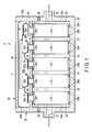
- FIG. 1 is a cross-sectional view illustrating the secondary battery apparatus 11 according to the first embodiment.
- the secondary battery apparatus 11 includes a box-shaped outer case 24; a liquid coolant 27 which is filled in the outer case; a plurality of battery cells (secondary batteries) 23 which are stored in the outer case and immersed in the liquid coolant 27; a cell monitoring unit (CMU) 30 which is disposed in the outer case and monitors the voltage and temperature of the battery cells; and a plurality of conductor members (bus bars) 31 which electrically connect the battery cells.
- CMU cell monitoring unit
- the outer case 24 includes a rectangular box-shaped body case 25 which is opened at its upper surface, and has a bottom; an upper case 26 which covers the opening of the upper surface of the body case 25; and a cover 17 covering the upper case.
- the body case 25 and upper case 26 are fabricated by, for example, an injection molding method, by using a synthetic resin with insulation properties, for example, a thermoplastic resin such as polycarbonate (PC) or polyphenylene ether (PPE).
- the cover 17 is formed of a relatively soft resin, for instance, polypropylene, so that the cover 17 can be easily attached/detached.
- the body case 25 includes, as one piece, a rectangular bottom wall 25a, and a rectangular frame-shaped peripheral wall 25b which is erectly provided along each side of the bottom wall 25a.
- the bottom wall 25a is formed to have a size corresponding to a predetermined number of battery cells 23, for example, ten battery cells 23.
- the peripheral wall 25b is formed to have a height which is about 90% of the height of the battery cell 23.
- the body case 25 includes an upper opening through which the battery cells 23 can be passed.
- the upper case 26 includes, as one piece, a ceiling wall 26a having substantially the same size and shape as the bottom wall 25a of the body case 25, and a rectangular frame-shaped peripheral wall 26b formed around the ceiling wall 26a.
- the upper case 26 is laid over the body case 25 from above, and is attached to the body case 25.
- the outer case 24 having a rectangular box shape as a whole is constructed.
- the upper case 26 is fixed such that a lower end edge of the peripheral wall 26b is abutted upon an upper end edge of the peripheral wall 25b of the body case 25.
- an adhesive 29 is filled in an annular groove which is formed along the upper end edge of the peripheral wall 25b of the body case 25, and the upper end of the peripheral wall 25b and the lower end of the peripheral wall 26b are airtightly adhered by this adhesive 29.
- an adhesive which, when dried, does not vary in volume is used, and the adhesive 29 functions also as a sealant for airtightly sealing the jointing part.
- fixation between the body case 25 and upper case 26 may be made by screwing, fastening by bolts, etc.
- a sealing member such as an O-ring, may be inserted in the jointing part, thereby to maintain airtightness.
- the ceiling wall 26a of the upper case 26 is opposed to the bottom wall 25a of the body case 25 such that the ceiling wall 26a is substantially in parallel to the bottom wall 25a.
- an airtight battery storing chamber 24a for storing the battery cells and liquid coolant is formed between the bottom wall 25a of the body case 25 and the ceiling wall 26a of the upper case 26.
- the cover 17 having a rectangular plate shape is detachably attached to the upper opening of the upper case 26, and covers the upper opening of the upper case.
- a conductor disposition chamber 24b for disposing the conductor members, CMU 30, etc. is formed between the ceiling wall 26a of the upper case 26 and the cover 17.
- the battery storing chamber 24a and the conductor disposition chamber 24b are airtightly partitioned by the ceiling wall 26a.
- a plurality of openings 40 for insertion of electrode terminals of the battery cells 23, and a plurality of exhaust ports (not shown) are formed in the ceiling wall 26a of the upper case 26.
- Each of the openings 40 is formed to be slightly larger than the electrode terminal of the battery cell 23.
- the openings 40 are arranged and provided in four rows in the longitudinal direction of the ceiling wall 26a.
- the exhaust ports are arranged and formed in two rows in the longitudinal direction of the ceiling wall 26a, and each row is provided at a substantially central part between two rows of openings 40.
- the outer case 24 includes a coolant inlet 21 and a coolant outlet 22 which communicate with the battery storing chamber 24a.
- the coolant inlet 21 is formed, for example, in the peripheral wall 25b of the body case 25, and is located on one end side in the longitudinal direction of the outer case 24.
- the coolant outlet 22 is formed, for example, in the peripheral wall 25b of the body case 25, and is located on the other end side in the longitudinal direction of the outer case 24.
- the coolant inlet 21 and coolant outlet 22 are provided on both sides of the battery storing chamber, with the battery storing chamber 24a being interposed.
- FIG. 2 is a perspective view illustrating the battery cell 23, as viewed from above.
- FIG. 3 is a perspective view illustrating a bottom side of the battery cell.
- the battery cell 23 for example, a nonaqueous electrolyte secondary battery, such as a lithium ion battery, is used.
- the battery cell 23 includes a flat, rectangular box-shaped, outer container 32 which is formed of, e.g. aluminum, and an electrode body 34 which, together with the nonaqueous electrolyte, is contained in the outer container 32.
- the outer container 32 includes a container body 33a which is opened at its upper end, and a rectangular plate-shaped cover member 33b which is welded to the container body 33a and closes the opening of the container body 33a, and the inside of the outer container 32 is airtightly formed.
- the electrode body 34 is formed in a flat rectangular shape, for example, by winding a cathode plate and an anode plate in a spiral shape, with a separator being interposed therebetween, and also by compressing the wound cathode plate and anode plate in the diametrical direction.
- a cathode terminal 35a and an anode terminal 35b are disposed at both end portions in the longitudinal direction of the cover member 33b, and project from the cover member 33b.
- the cathode terminal 35a and anode terminal 35b are connected to the cathode and anode of the electrode body 34, respectively.
- a pressure release valve 36 which functions as a gas exhaust mechanism, is formed at a central part of the cover member 33b.
- the pressure release valve 36 is formed to have about half the thickness of the cover member 33b.
- an adhesive 28a is applied to each battery cell 23 such that the adhesive 28a is provided around the peripheral edge of the cover member 33b.
- an adhesive 28b is independently applied to a plurality of locations on the bottom surface of the outer container 32, for example, four corner portions.
- a plurality of battery cells 23 are disposed and stored in the battery storing chamber 24a of the outer case 24.
- the battery cells 23 are arranged in two rows each including five battery cells 23, and each battery cell 23 is disposed at predetermined distances from the inner surface of the peripheral wall 25b of the outer case 24 and from other battery cells 23.
- the five battery cells 23 are arranged in such a state that the major surfaces of the outer containers 32 face each other with a predetermined gap, and that the upper ends of the outer containers 32, on which the electrode terminals 35a and 35b are provided, face in the same direction.
- the battery cells 23 are disposed such that the width direction of the battery cells 23 are parallel to a direction perpendicular to the longitudinal direction of the outer case 24.
- Two neighboring battery cells 23 are reversely disposed in opposite directions over 180° from each other, such that the cathode terminal 35a and anode terminal 35b neighbor each other.
- the battery cells 23 of the two neighboring rows are disposed such that the cathode terminal 35a of the battery cell 23 of one row and the anode terminal 35b of the battery cell 23 of the other row neighbor, and that the anode terminal 35b of the battery cell 23 of the one row and the cathode terminal 35a of the battery cell 23 of the other row neighbor.
- two neighboring battery cells 23 may be disposed in the same direction such that their cathode terminals 35a neighbor and their anode terminals 35b neighbor.
- each battery cell 23 the bottom of the outer container 32 is adhered and fixed to the inner surface of the bottom wall 25a of the outer case 24 by the adhesive 28b.
- a double coated adhesive tape or the like may be substituted for the adhesive 28b.
- the cathode terminal 35a and anode terminal 35b of the battery cell 23 are passed through the openings 40 of the ceiling wall 26a, penetrate the ceiling wall 26a, and project into the conductor disposition chamber 24b.
- the upper end of the outer container 32 is adhered and fixed to the lower surface of the ceiling wall 26a by the adhesive 28a.
- each battery cell 23 is aligned and fixed at a predetermined position in the battery storing chamber 24a.
- the adhesive 28a is adhered to the periphery of the opening 40, and effects airtight sealing between the battery storing chamber 24a and the opening 40.
- the battery storing chamber 24a is kept airtight.
- a plurality of bus bars 31 serving as conductor members are disposed within the conductor disposition chamber 24b of the outer case 24.
- the plural battery cells 23 are electrically connected to each other by the bus bars 31, and are connected in series or in parallel.
- the bus bar 31 is formed by bending and forming an electrically conductive material, for instance, a metal plate of aluminum or the like.
- the cathode terminals 35a and anode terminals 35b, which project into the conductor disposition chamber 24b are mutually electrically connected by the bus bar 31.
- the bus bar 31 is electrically and mechanically connected to the electrode terminal of the battery cell 23 by, for example, laser welding, electron beam welding or resistance welding.
- the bus bars 31, which are connected to the battery cells 23 located at both ends of the row constitute a cathode-side output terminal and an anode-side output terminal of the secondary battery apparatus 11.
- the CMU 30 is composed of a rectangular control circuit board, and is disposed within the conductor disposition chamber 24b of the upper case 26.
- the CMU 30 is placed above the ceiling wall 26a, with an insulation sheet (not shown) being interposed, and covers most of the bus bars 31.
- the CMU 30 is fixed to a plurality of bosses, support ribs or the like (not shown), which are erectly provided on the ceiling wall 26a.
- the CMU 30 is electrically connected to the respective battery cells 23 via the bus bars 31.
- the CMU 30 detects the voltage and temperature of each battery cell 23, and delivers information to a controller (not shown). In accordance with the voltage and temperature of each battery cell 23, which are delivered from the CMU 30, the controller controls the operation of the secondary battery apparatus 11, and prevents over-charge or over-discharge of the battery cells 23.
- the liquid coolant 27 with electrical insulation properties for instance, an insulation oil, a transformer oil, triphenyl phosphate, trioctyl phosphate, hydrofluoroether, or a fluorine-based inactive liquid, is filled in the battery storing chamber 24a of the outer case 24, and the battery storing chamber is filled with the liquid coolant 27.
- This liquid coolant 27 is supplied and filled in the battery storing chamber 24a from the coolant inlet 21, and is also discharged from the battery storing chamber 24a through the coolant outlet 22.
- the plural battery cells 23 are immersed in the liquid coolant 27 and are directly cooled by the liquid coolant.
- the liquid coolant 27 flows to the periphery of the outer container 32 of each battery cell 23, and further flows between the bottom of the outer container 32 and the bottom wall 25a of the outer case 24, thus directly cooling the battery cells 23 from their peripheries.
- the battery storing chamber 24a is airtightly partitioned, the liquid coolant 27 does not flow or leak into the conductor disposition chamber 24b of the outer case 24, and the liquid coolant 27 does not come in contact with the bus bars 31 or CMU 30. Therefore, the CMU 30 can surely detect the temperature and voltage of the battery cells 23, without being hindered by the liquid coolant 27.
- FIG. 4 illustrates a secondary battery system 10 according to the first embodiment.
- the secondary battery system 10 includes at least one, for example, two secondary battery apparatuses 11a and 11b, and a circulation mechanism 20 for supplying and circulating a liquid coolant to these secondary battery apparatuses.
- the circulation mechanism 20 includes a pump 12, an air blower 13, a radiator 14, a reservoir tank 15, and a piping 16 for communication between these components and the secondary battery apparatuses 11a and 11b.
- the secondary battery system 10 includes a controller (not shown) which controls the operation of the circulation mechanism 20.
- the secondary battery apparatuses 11a and 11b are constructed like the above-described secondary battery apparatus 11.
- the secondary battery system 10 includes two secondary battery apparatuses 11, namely secondary battery apparatuses 11a and 11b, the number of secondary battery apparatuses, which the secondary battery system 10 includes, is not limited to a specific number.
- a discharge port of the pump 12 is connected to the coolant inlet 21 of the secondary battery apparatus 11a through the piping 16.
- a suction port of the pump 12 is connected to a discharge port of the radiator 14 through the piping 16.
- the pump 12 takes in the liquid coolant 27 from the discharge port of the radiator 14, and discharges the taken-in liquid coolant 27 to the coolant inlet 21 of the secondary battery apparatus 11a.
- the coolant outlet 22 of the secondary battery apparatus 11a is connected to the coolant inlet 21 of the secondary battery apparatus 11b through the piping 16.
- the coolant outlet 22 of the secondary battery apparatus 11b is connected to an inlet of the radiator 14.
- the reservoir tank 15 is disposed midway along the piping which connects the coolant outlet 22 of the secondary battery apparatus 11b and the inlet of the radiator 14.
- the battery storing chamber 24a of the secondary battery apparatus 11a, 11b and each piping 16 are filled with the liquid coolant 27.
- a part of the liquid coolant 27 is stored in the reservoir tank 15.
- the air blower 13 is provided to be opposed to the radiator 14, and feeds a cooling wind to the radiator.
- the liquid coolant 27 passing through the radiator 14 is air-cooled by the cooling wind from the air blower 13 and by natural cooling.
- a fan is used as the air blower 13, but the air blower 13 is not limited to a specific device.
- each of the air blower 13 and radiator 14 is a cooling device for cooling the liquid coolant 27, the cooling device is not limited to a specific structure.
- the air blower may be omitted and only the radiator 14 may be provided as the cooling device.
- the controller controls the overall operation of the secondary battery system 10.
- the controller is composed of a processor such as a CPU, various memories, and various interfaces.
- the controller may be composed of, for instance, a personal computer (PC).
- the controller is connected to the respective components of the secondary battery system 10, such as the CMUs 30 of the secondary battery apparatuses 11a and 11b, the pump 12 and the air blower 13.
- the controller acquires various measurement data, etc. from the respective parts of the secondary battery system 10, and comprehensively controls the respective parts of the secondary battery system 10, based on the acquired various measurement data, etc.
- the pump 12 feeds the liquid coolant 27 from the discharge port into the piping 16 at a predetermined pressure.
- the fed-out liquid coolant 27 passes through the piping 16, and flows into the battery storing chamber 24a from the coolant inlet 21 of the secondary battery apparatus 11a.
- the liquid coolant 27 passes through the battery storing chamber 24a, absorbs heat from the battery cells 23 in the battery storing chamber, and cools the battery cells 23. Thereafter, the liquid coolant 27 is exhausted from the coolant outlet 22 of the secondary battery apparatus 11a to the piping 16.
- the liquid coolant 27 passes through the battery storing chamber 24a, absorbs heat from the battery cells 23 in the battery storing chamber, and cools the battery cells 23. Thereafter, the liquid coolant 27 is exhausted from the coolant outlet 22 of the secondary battery apparatus 11b to the piping 16.
- the amount of the liquid coolant 27 in the entirety of the secondary battery system 10 exceeds a predetermined amount, or if the pressure of the liquid coolant in the secondary battery system exceeds a predetermined value, a part of the liquid coolant 27 is fed from the piping 16 to the reservoir tank 15, and is recovered in the reservoir tank.
- the amount of the liquid coolant 27 in the secondary battery system 10 becomes short of a predetermined amount, the liquid coolant 27 is replenished from the reservoir tank 15 into the system through the piping 16. Thereby, the amount of the liquid coolant 27 in the secondary battery system 10 is kept constant.
- the water cooling jacket and the piping structure on its periphery are needless. Therefore, the structure can be simplified, the efficiency in assembly can be enhanced, and the manufacturing cost can be reduced. In addition, there is no need to provide the water cooling jacket in the secondary battery apparatus or on the outer surface of the secondary battery apparatus, and the apparatus can be reduced in size. Furthermore, by directly cooling the battery cells by the coolant, the cooling efficiency can be greatly improved, compared to air cooling. At the same time, battery cells, which cannot sufficiently be cooled by the water cooling jacket, can effectively be cooled.
- the liquid coolant with electrical insulation properties for example, an insulation oil is used.
- the problems of occurrence of rust and electrical conductivity, which arise from water cooling can be solved.
- two functions namely the ensuring of airtightness and the fixing of battery cells, can be achieved by the adhesive, and the volume energy efficiency can be improved.
- the present secondary battery system by directly circulating the liquid coolant in the secondary battery apparatus, the secondary battery apparatus can effectively be cooled while the amount of use of the liquid coolant is reduced. Moreover, dew condensation in the secondary battery apparatus can also be prevented.
- FIG. 5 is a cross-sectional view illustrating a secondary battery apparatus 11 according to the second embodiment.
- the second embodiment differs from the first embodiment in that an O-ring 37 is used in place of the adhesive 29, as a sealing member for airtightly sealing a jointing part between the peripheral wall 25b of the body case 25 and the peripheral wall 26b of the upper case 26.
- the other structure of the secondary battery apparatus is the same as that of the secondary battery apparatus according to the first embodiment.
- the body case 25 and upper case 26 are fastened with a bolt, and the O-ring 37 is interposed between the upper end edge of the peripheral wall 25b and the lower end edge of the peripheral wall 26b.
- the O-ring 37 is an elastic body, and is formed of a metal, synthetic resin, etc. The jointing parts of the body case 25 and upper case 26 are airtightly jointed by the O-ring 37.
- FIG. 6 is a cross-sectional view illustrating a secondary battery apparatus 11 according to the third embodiment.
- FIG. 7 is a perspective view of a battery cell, illustrating a state in which an adhesive is applied to the batter cell.
- the third embodiment differs from the first embodiment with respect to the sealing structure between the ceiling wall 26a of the upper case 26 and each battery cell 23.
- the other structure of the secondary battery apparatus is the same as that of the secondary battery apparatus according to the first embodiment.
- the upper case 26 includes a plurality of fixing ribs 26e projecting from the lower surface of the ceiling wall 26a toward the battery storing chamber 24a.
- Each fixing rib 26e extends in a manner to surround the periphery of two openings 40 provided in the ceiling wall 26a.
- the fixing rib 26e is formed to have a height which is about 10% of the height of the outer container 32 excluding the terminals of the battery cell 23, and the fixing rib 26e faces the outer periphery of an upper end portion of each battery cell 23.
- parts of the fixing ribs, which are disposed at both ends in the longitudinal direction of the ceiling wall 26a are formed by the peripheral wall of the upper case 26.
- the adhesive 28a is applied, with a predetermined width, around the outer periphery of the upper end portion of the outer container 32 of the battery cell 23.
- the upper end portion of the outer container 32 of each battery cell 23 is airtightly adhered and fixed to the fixing rib 26e or the inner surface of the peripheral wall 26b by the adhesive 28a.
- Each battery cell 23 is aligned and fixed at a predetermined position within the battery storing chamber 24a, and, furthermore, the adhesive 28a effects airtight sealing between the battery storing chamber 24a and the opening 40.
- the battery storing chamber 24a and the conductor disposition chamber 24b of the outer case 24 are formed as mutually independent spaces, and the battery storing chamber 24 is kept airtight.
- FIG. 8 is a cross-sectional view illustrating a secondary battery apparatus 11 according to the fourth embodiment.
- the fourth embodiment differs from the first embodiment in that an insulation member is disposed between two neighboring battery cells 23 within the battery storing chamber 24a.
- the other structure of the secondary battery apparatus is the same as that of the secondary battery apparatus according to the first embodiment.
- an insulation member 38 is formed of an insulator in a rectangular plate shape.
- the insulation member 38 is disposed between two neighboring battery cells 23 within the battery storing chamber 24a, and faces the battery cells 23 with a predetermined gap.
- the insulation member 38 has a height which is substantially equal to the distance from the bottom surface of the body case 25 to the ceiling wall 26a of the upper case 26, has a width which is substantially equal to the width of the battery cell 23, and is formed to have a thickness which is less than the interval between the battery cells 23.
- the insulator, of which the insulation member 38 is formed, is not limited to a specific material.
- Each insulation member 38 is disposed between the battery cells 23 by fixing its lower end edge to the bottom wall 25a of the body case 25 and fixing its upper end edge to the ceiling wall 26a of the upper case 26. In addition, each insulation member 38 is not in contact with the peripheral wall 25b of the body case 25 or the peripheral wall 26b of the upper case 26, and is opposed to, with a gap, to the peripheral wall 25b and peripheral wall 26b.
- the neighboring battery cells 23 can surely be insulated by the insulation member 38.
- the insulation member 38 For example, when the battery cell 23 expands due to over-charge or the like, electrical contact between the battery cells 23 can be prevented by the insulation member 38.
- FIG. 9 is a cross-sectional view illustrating a secondary battery apparatus 11 according to the fifth embodiment.
- the fifth embodiment differs from the first embodiment in that the outer case 24 is composed of three or more parts, namely a lower case 43, a middle case 39 and an upper case 26. Specifically, the case, which corresponds to the body case 25 of the first embodiment, is divided into the middle case 39 and lower case 43, and these cases are jointed to constitute the body case.
- the other structure of the secondary battery apparatus is the same as that of the secondary battery apparatus according to the first embodiment.
- the lower case 43 includes, as one piece, a rectangular bottom wall 43a and a rectangular frame-shaped peripheral wall 43b which is erectly provided around the bottom wall 43a.
- the bottom wall 43a is formed to have a size corresponding to a predetermined number of battery cells 23.
- the peripheral wall 43b has a height which is about 20% of the height of the battery cell 23.
- the middle case 39 is formed in a rectangular frame shape with a size corresponding to the peripheral wall 43b of the lower case 43.
- the middle case 39 is formed to have a height which is about 70% of the height of the battery cell 23.
- the upper end edge of the peripheral wall 43b of the lower case 43 and the lower end edge of the peripheral wall of the middle case 39 are abutted upon each other, and are airtightly adhered by the adhesive 29.
- the upper end edge of the peripheral wall of the middle case 39 and the lower end edge of the peripheral wall 26b of the upper case 26 are abutted upon each other, and are airtightly adhered by the adhesive 29.
- the airtight battery storing chamber 24a is formed by the lower case 43, the middle case 39, and the ceiling wall 26a and peripheral wall 26b of the upper case 26.
- the coolant inlet 21 of the outer case 24 is formed on one end side of the peripheral wall of the middle case 39, and communicates with the battery storing chamber 24a.
- the coolant outlet 22 is formed in that peripheral wall of the middle case 39, which is located on the side opposite to the peripheral wall at which the coolant inlet 21 is disposed, and communicates with the battery storing chamber 24a.
- the outer case 24 is composed of the three parts, namely the upper case 26, middle case 39 and lower case 43. Thereby, the size of each structural member can be reduced, and the efficiency in manufacture and assembly can be improved.
- FIG. 10 is a cross-sectional view illustrating a secondary battery apparatus 11 according to the sixth embodiment.
- the sixth embodiment differs from the first embodiment with respect to the point that the coolant inlet 21 and coolant outlet 22 are disposed at the bottom wall 25a of the body case 25, and with respect to the sealing structure between the battery cell 23 and the ceiling wall 26a of the upper case 26.
- the other structure of the secondary battery apparatus is the same as that of the secondary battery apparatus according to the first embodiment.
- the sealing structure between the battery cell 23 and the ceiling wall 26a of the upper case 26 is the same as that of the secondary battery apparatus of the third embodiment, a detailed description thereof is omitted.
- the coolant inlet 21 is formed downward, on one end side of the bottom wall 25a, and communicates with the battery storing chamber 24a.
- the coolant outlet 22 is formed downward in that end portion of the bottom wall 25a, which is opposite to the side of the location where the coolant inlet 21 is disposed, and communicates with the battery storing chamber 24a.
- the secondary battery apparatus 11 with the above-described structure can be used, for example, in the case where the liquid coolant 27 cannot be taken in or discharged from the peripheral wall side of the outer case, because of the presence of other members around the secondary battery apparatus 11, depending on the location of installation or the direction of installation.
- FIG. 11 is a cross-sectional view illustrating a secondary battery apparatus 11 according to the seventh embodiment.
- the seventh embodiment differs from the first embodiment in that the secondary battery apparatus 11 includes a liquid coolant drain hole (drain) formed in the body case 25, and a pressure sensor.
- the other structure of the secondary battery apparatus is the same as that of the secondary battery apparatus according to the first embodiment.
- the secondary battery apparatus 11 according to the seventh embodiment further includes an insulation oil drain 41 and a liquid pressure sensor 42.
- the liquid coolant drain hole (drain) 41 is formed in the bottom wall 25a of the body case 25, communicates with the battery storing chamber 24a, and is open to the outer surface of the body case 25.
- the liquid coolant 27 in the battery storing chamber 24a can be exhausted to the outside from the liquid coolant drain 41.
- the liquid coolant drain 41 is closed by a detachable cap 41b.
- the pressure sensor 42 is a sensor which measures a pressure acting on the liquid coolant 27 which is filled in the battery storing chamber 24a.
- This pressure sensor 42 for example, is embedded in the peripheral wall 25b of the body case 25, and a detection part thereof is in contact with the inside of the battery storing chamber 24a.
- the structure of the pressure sensor 42 is not limited to a specific structure.
- the pressure sensor 42 sends measured pressure data of the liquid coolant 27 to the CMU 30 and the controller.
- the controller executes various processes, based on the pressure data of the liquid coolant 27. For example, if the controller determines that the pressure acting on the liquid coolant 27 has lowered below a predetermined pressure, the controller raises the pressure of the pump 12. Conversely, if the controller determines that the pressure of the liquid coolant 27 has increased above the predetermined pressure, the controller lowers the pressure of the pump 12. In addition, if the pressure of the liquid coolant 27 in the battery storing chamber 24a has excessively increased, the controller can also stop the liquid feed of the pump 12.
- the internal liquid coolant 27 can easily be completely drained where necessary.
- the liquid coolant circulation operation can properly be controlled in accordance with the detected pressure.
- the secondary battery apparatus 11 may include a temperature sensor which detects the temperature of the liquid coolant 27 in the battery storing chamber 24a. By controlling the operations of the pump, radiator and air blower in accordance with the temperature of the liquid coolant 27, which was detected by the temperature sensor, the battery cells can be cooled more stably.
- the secondary battery apparatuses can be connected in parallel with the circulation mechanism of the secondary battery system, or may be connected in a combination of serial connection and parallel connection.
- the battery cells may be disposed in the battery storing chamber such that the major surfaces of the outer containers of the battery cells are parallel to the coolant inlet and outlet.
Landscapes
- Chemical & Material Sciences (AREA)
- Chemical Kinetics & Catalysis (AREA)
- Electrochemistry (AREA)
- General Chemical & Material Sciences (AREA)
- Engineering & Computer Science (AREA)
- Manufacturing & Machinery (AREA)
- Battery Mounting, Suspending (AREA)
- Secondary Cells (AREA)
- Sealing Battery Cases Or Jackets (AREA)
Abstract
Description
- Embodiments described herein relate generally to a secondary battery apparatus and a secondary battery system.
- Battery cells, which are stored in a secondary battery apparatus, produce heat by being charged/discharged. In a case of operating the secondary battery apparatus at a high rate, the amount of heat produced from the battery cells increases. It is thus necessary to cool the battery cells in accordance with the heat production of the battery cells. As a general cooling method, heat removal by air cooling is thought. However, air cooling has a problem that the cooling capability is low. In addition, as another cooling method, there is thought a method in which a water cooling jacket is disposed within the secondary battery apparatus or on the outer surface of the apparatus, and cooling water is circulated in the water cooling jacket.
-
- Patent document 1: Jpn. Pat. Appln. KOKAI Publication No.
2000-251953 - Patent document 2: Jpn. Pat. Appln. KOKAI Publication No.
2000-348781 - Patent document 3: Jpn. Pat. Appln. KOKAI Publication No.
H6-215804 - In the above-described cooling method, however, battery cells, which are distant from the water cooling jacket, cannot fully be cooled, and a temperature distribution in the secondary battery apparatus becomes large. Thus, large temperature differences occur among the battery cells, and the charging/discharging capability of the secondary battery apparatus lowers, and the lifetime of charging/discharging of the secondary battery apparatus considerably decreases. In addition, when water cooling jackets are disposed close to the battery cells, the number of water cooling jackets increases, the size of the secondary battery apparatus increases, the volume energy density of the secondary battery apparatus decreases, and the manufacturing cost increases.
- This invention has been made in consideration of the above points, and the object of the invention is to provide a secondary battery apparatus and a secondary battery system, which can effectively cool battery cells, without increasing the size of the apparatus.
- A secondary battery apparatus according to an embodiment includes an outer case including an airtight battery storing chamber formed inside, a coolant inlet for supplying an insulative liquid coolant to the battery storing chamber, and a coolant outlet for discharging the liquid coolant from the battery storing chamber; and a battery cell including an electrode terminal, the battery cell being disposed in the battery storing chamber of the outer case and immersed in the liquid coolant filled in the battery storing chamber.
-
-
FIG. 1 is a cross-sectional view which schematically illustrates a secondary battery apparatus according to a first embodiment. -
FIG. 2 is a perspective view illustrating a battery cell in the secondary battery apparatus. -
FIG. 3 is a perspective view illustrating a bottom surface side of the battery cell. -
FIG. 4 is a view which schematically illustrates a secondary battery system according to the first embodiment. -
FIG. 5 is a cross-sectional view which schematically illustrates a secondary battery apparatus according to a second embodiment. -
FIG. 6 is a cross-sectional view which schematically illustrates a secondary battery apparatus according to a third embodiment. -
FIG. 7 is a perspective view illustrating a battery cell in the secondary battery apparatus according to the third embodiment. -
FIG. 8 is a cross-sectional view which schematically illustrates a secondary battery apparatus according to a fourth embodiment. -
FIG. 9 is a cross-sectional view which schematically illustrates a secondary battery apparatus according to a fifth embodiment. -
FIG. 10 is a cross-sectional view which schematically illustrates a secondary battery apparatus according to a sixth embodiment. -
FIG. 11 is a cross-sectional view which schematically illustrates a secondary battery apparatus according to a seventh embodiment. - Secondary battery apparatuses and secondary battery systems according to various embodiments will now be described in detail with reference to the accompanying drawings.
- In a secondary battery apparatus according to an embodiment, battery cells are directly immersed in a liquid coolant with insulation properties, and the battery cells are cooled. A secondary battery system according to an embodiment is a system in which a liquid coolant is circulated in a secondary battery apparatus, thereby cooling battery cells which are stored in the secondary battery apparatus.
- A
secondary battery apparatus 11 according to a first embodiment is described.FIG. 1 is a cross-sectional view illustrating thesecondary battery apparatus 11 according to the first embodiment. - The
secondary battery apparatus 11 includes a box-shapedouter case 24; aliquid coolant 27 which is filled in the outer case; a plurality of battery cells (secondary batteries) 23 which are stored in the outer case and immersed in theliquid coolant 27; a cell monitoring unit (CMU) 30 which is disposed in the outer case and monitors the voltage and temperature of the battery cells; and a plurality of conductor members (bus bars) 31 which electrically connect the battery cells. - The
outer case 24 includes a rectangular box-shaped body case 25 which is opened at its upper surface, and has a bottom; anupper case 26 which covers the opening of the upper surface of thebody case 25; and acover 17 covering the upper case. Thebody case 25 andupper case 26 are fabricated by, for example, an injection molding method, by using a synthetic resin with insulation properties, for example, a thermoplastic resin such as polycarbonate (PC) or polyphenylene ether (PPE). Thecover 17 is formed of a relatively soft resin, for instance, polypropylene, so that thecover 17 can be easily attached/detached. - The
body case 25 includes, as one piece, arectangular bottom wall 25a, and a rectangular frame-shapedperipheral wall 25b which is erectly provided along each side of thebottom wall 25a. Thebottom wall 25a is formed to have a size corresponding to a predetermined number ofbattery cells 23, for example, tenbattery cells 23. Theperipheral wall 25b is formed to have a height which is about 90% of the height of thebattery cell 23. Thebody case 25 includes an upper opening through which thebattery cells 23 can be passed. - The
upper case 26 includes, as one piece, aceiling wall 26a having substantially the same size and shape as thebottom wall 25a of thebody case 25, and a rectangular frame-shapedperipheral wall 26b formed around theceiling wall 26a. Theupper case 26 is laid over thebody case 25 from above, and is attached to thebody case 25. Thereby, theouter case 24 having a rectangular box shape as a whole is constructed. Specifically, theupper case 26 is fixed such that a lower end edge of theperipheral wall 26b is abutted upon an upper end edge of theperipheral wall 25b of thebody case 25. For example, an adhesive 29 is filled in an annular groove which is formed along the upper end edge of theperipheral wall 25b of thebody case 25, and the upper end of theperipheral wall 25b and the lower end of theperipheral wall 26b are airtightly adhered by this adhesive 29. As theadhesive 29, an adhesive which, when dried, does not vary in volume is used, and theadhesive 29 functions also as a sealant for airtightly sealing the jointing part. - Incidentally, the fixation between the
body case 25 andupper case 26 may be made by screwing, fastening by bolts, etc. In addition, a sealing member, such as an O-ring, may be inserted in the jointing part, thereby to maintain airtightness. - The
ceiling wall 26a of theupper case 26 is opposed to thebottom wall 25a of thebody case 25 such that theceiling wall 26a is substantially in parallel to thebottom wall 25a. Thereby, in theouter case 24, an airtightbattery storing chamber 24a for storing the battery cells and liquid coolant is formed between thebottom wall 25a of thebody case 25 and theceiling wall 26a of theupper case 26. In addition, thecover 17 having a rectangular plate shape is detachably attached to the upper opening of theupper case 26, and covers the upper opening of the upper case. Thereby, aconductor disposition chamber 24b for disposing the conductor members,CMU 30, etc. is formed between theceiling wall 26a of theupper case 26 and thecover 17. Thebattery storing chamber 24a and theconductor disposition chamber 24b are airtightly partitioned by theceiling wall 26a. - A plurality of
openings 40 for insertion of electrode terminals of thebattery cells 23, and a plurality of exhaust ports (not shown) are formed in theceiling wall 26a of theupper case 26. Each of theopenings 40 is formed to be slightly larger than the electrode terminal of thebattery cell 23. Theopenings 40 are arranged and provided in four rows in the longitudinal direction of theceiling wall 26a. The exhaust ports are arranged and formed in two rows in the longitudinal direction of theceiling wall 26a, and each row is provided at a substantially central part between two rows ofopenings 40. - Furthermore, the
outer case 24 includes acoolant inlet 21 and acoolant outlet 22 which communicate with thebattery storing chamber 24a. Thecoolant inlet 21 is formed, for example, in theperipheral wall 25b of thebody case 25, and is located on one end side in the longitudinal direction of theouter case 24. Thecoolant outlet 22 is formed, for example, in theperipheral wall 25b of thebody case 25, and is located on the other end side in the longitudinal direction of theouter case 24. Specifically, thecoolant inlet 21 andcoolant outlet 22 are provided on both sides of the battery storing chamber, with thebattery storing chamber 24a being interposed. - Next, the
battery cell 23 is described.FIG. 2 is a perspective view illustrating thebattery cell 23, as viewed from above.FIG. 3 is a perspective view illustrating a bottom side of the battery cell. - As the
battery cell 23, for example, a nonaqueous electrolyte secondary battery, such as a lithium ion battery, is used. As illustrated inFIG. 2 and FIG. 3 , thebattery cell 23 includes a flat, rectangular box-shaped,outer container 32 which is formed of, e.g. aluminum, and anelectrode body 34 which, together with the nonaqueous electrolyte, is contained in theouter container 32. Theouter container 32 includes acontainer body 33a which is opened at its upper end, and a rectangular plate-shapedcover member 33b which is welded to thecontainer body 33a and closes the opening of thecontainer body 33a, and the inside of theouter container 32 is airtightly formed. Theelectrode body 34 is formed in a flat rectangular shape, for example, by winding a cathode plate and an anode plate in a spiral shape, with a separator being interposed therebetween, and also by compressing the wound cathode plate and anode plate in the diametrical direction. - A
cathode terminal 35a and ananode terminal 35b are disposed at both end portions in the longitudinal direction of thecover member 33b, and project from thecover member 33b. Thecathode terminal 35a andanode terminal 35b are connected to the cathode and anode of theelectrode body 34, respectively. Apressure release valve 36, which functions as a gas exhaust mechanism, is formed at a central part of thecover member 33b. Thepressure release valve 36 is formed to have about half the thickness of thecover member 33b. When gas occurs in theouter container 32 due to, for example, an abnormal mode of thebattery cell 23, and the internal pressure of theouter container 32 rises to a predetermined value or more, thepressure release valve 36 is opened. By the opening of thepressure release valve 36, the pressure in theouter container 32 lowers, and breakage or the like of theouter container 32 is prevented. - As illustrated in
FIG. 2 , an adhesive 28a is applied to eachbattery cell 23 such that the adhesive 28a is provided around the peripheral edge of thecover member 33b. In addition, as illustrated inFIG. 3 , an adhesive 28b is independently applied to a plurality of locations on the bottom surface of theouter container 32, for example, four corner portions. - As illustrated in
FIG. 1 , a plurality ofbattery cells 23 are disposed and stored in thebattery storing chamber 24a of theouter case 24. Thebattery cells 23 are arranged in two rows each including fivebattery cells 23, and eachbattery cell 23 is disposed at predetermined distances from the inner surface of theperipheral wall 25b of theouter case 24 and fromother battery cells 23. In each row, the fivebattery cells 23 are arranged in such a state that the major surfaces of theouter containers 32 face each other with a predetermined gap, and that the upper ends of theouter containers 32, on which theelectrode terminals battery cells 23 are disposed such that the width direction of thebattery cells 23 are parallel to a direction perpendicular to the longitudinal direction of theouter case 24. - Two neighboring
battery cells 23 are reversely disposed in opposite directions over 180° from each other, such that thecathode terminal 35a andanode terminal 35b neighbor each other. Thebattery cells 23 of the two neighboring rows are disposed such that thecathode terminal 35a of thebattery cell 23 of one row and theanode terminal 35b of thebattery cell 23 of the other row neighbor, and that theanode terminal 35b of thebattery cell 23 of the one row and thecathode terminal 35a of thebattery cell 23 of the other row neighbor. Incidentally, two neighboringbattery cells 23 may be disposed in the same direction such that theircathode terminals 35a neighbor and theiranode terminals 35b neighbor. - As regards each
battery cell 23, the bottom of theouter container 32 is adhered and fixed to the inner surface of thebottom wall 25a of theouter case 24 by the adhesive 28b. Incidentally a double coated adhesive tape or the like may be substituted for the adhesive 28b. In addition, thecathode terminal 35a andanode terminal 35b of thebattery cell 23 are passed through theopenings 40 of theceiling wall 26a, penetrate theceiling wall 26a, and project into theconductor disposition chamber 24b. The upper end of theouter container 32 is adhered and fixed to the lower surface of theceiling wall 26a by the adhesive 28a. Thereby, eachbattery cell 23 is aligned and fixed at a predetermined position in thebattery storing chamber 24a. At this time, the adhesive 28a is adhered to the periphery of theopening 40, and effects airtight sealing between thebattery storing chamber 24a and theopening 40. Thereby, thebattery storing chamber 24a is kept airtight. - As illustrated in
FIG. 1 , a plurality ofbus bars 31 serving as conductor members are disposed within theconductor disposition chamber 24b of theouter case 24. Theplural battery cells 23 are electrically connected to each other by the bus bars 31, and are connected in series or in parallel. Thebus bar 31 is formed by bending and forming an electrically conductive material, for instance, a metal plate of aluminum or the like. In two neighboringbattery cells 23, thecathode terminals 35a andanode terminals 35b, which project into theconductor disposition chamber 24b, are mutually electrically connected by thebus bar 31. Thebus bar 31 is electrically and mechanically connected to the electrode terminal of thebattery cell 23 by, for example, laser welding, electron beam welding or resistance welding. In addition, of the plural bus bars 31, the bus bars 31, which are connected to thebattery cells 23 located at both ends of the row, constitute a cathode-side output terminal and an anode-side output terminal of thesecondary battery apparatus 11. - As illustrated in
FIG. 1 , theCMU 30 is composed of a rectangular control circuit board, and is disposed within theconductor disposition chamber 24b of theupper case 26. TheCMU 30 is placed above theceiling wall 26a, with an insulation sheet (not shown) being interposed, and covers most of the bus bars 31. TheCMU 30 is fixed to a plurality of bosses, support ribs or the like (not shown), which are erectly provided on theceiling wall 26a. - The
CMU 30 is electrically connected to therespective battery cells 23 via the bus bars 31. TheCMU 30 detects the voltage and temperature of eachbattery cell 23, and delivers information to a controller (not shown). In accordance with the voltage and temperature of eachbattery cell 23, which are delivered from theCMU 30, the controller controls the operation of thesecondary battery apparatus 11, and prevents over-charge or over-discharge of thebattery cells 23. - In the
secondary battery apparatus 11 with the above-described structure, theliquid coolant 27 with electrical insulation properties, for instance, an insulation oil, a transformer oil, triphenyl phosphate, trioctyl phosphate, hydrofluoroether, or a fluorine-based inactive liquid, is filled in thebattery storing chamber 24a of theouter case 24, and the battery storing chamber is filled with theliquid coolant 27. Thisliquid coolant 27 is supplied and filled in thebattery storing chamber 24a from thecoolant inlet 21, and is also discharged from thebattery storing chamber 24a through thecoolant outlet 22. Thereby, in thebattery storing chamber 24a, theplural battery cells 23 are immersed in theliquid coolant 27 and are directly cooled by the liquid coolant. Theliquid coolant 27 flows to the periphery of theouter container 32 of eachbattery cell 23, and further flows between the bottom of theouter container 32 and thebottom wall 25a of theouter case 24, thus directly cooling thebattery cells 23 from their peripheries. At this time, since thebattery storing chamber 24a is airtightly partitioned, theliquid coolant 27 does not flow or leak into theconductor disposition chamber 24b of theouter case 24, and theliquid coolant 27 does not come in contact with the bus bars 31 orCMU 30. Therefore, theCMU 30 can surely detect the temperature and voltage of thebattery cells 23, without being hindered by theliquid coolant 27. At the same time, there is no need to seal theCMU 30, and the structure can be simplified. - Next, a description is given of a secondary battery system including the secondary battery apparatus with the above-described structure.
-
FIG. 4 illustrates asecondary battery system 10 according to the first embodiment. As illustrated inFIG. 4 , thesecondary battery system 10 includes at least one, for example, twosecondary battery apparatuses circulation mechanism 20 for supplying and circulating a liquid coolant to these secondary battery apparatuses. Thecirculation mechanism 20 includes apump 12, anair blower 13, aradiator 14, areservoir tank 15, and a piping 16 for communication between these components and thesecondary battery apparatuses secondary battery system 10 includes a controller (not shown) which controls the operation of thecirculation mechanism 20. - The
secondary battery apparatuses secondary battery apparatus 11. In addition, in the example illustrated inFIG. 4 , although thesecondary battery system 10 includes twosecondary battery apparatuses 11, namelysecondary battery apparatuses secondary battery system 10 includes, is not limited to a specific number. - A discharge port of the
pump 12 is connected to thecoolant inlet 21 of thesecondary battery apparatus 11a through thepiping 16. In addition, a suction port of thepump 12 is connected to a discharge port of theradiator 14 through thepiping 16. Thepump 12 takes in theliquid coolant 27 from the discharge port of theradiator 14, and discharges the taken-inliquid coolant 27 to thecoolant inlet 21 of thesecondary battery apparatus 11a. - The
coolant outlet 22 of thesecondary battery apparatus 11a is connected to thecoolant inlet 21 of thesecondary battery apparatus 11b through thepiping 16. Thecoolant outlet 22 of thesecondary battery apparatus 11b is connected to an inlet of theradiator 14. - The
reservoir tank 15 is disposed midway along the piping which connects thecoolant outlet 22 of thesecondary battery apparatus 11b and the inlet of theradiator 14. In addition, thebattery storing chamber 24a of thesecondary battery apparatus liquid coolant 27. Besides, a part of theliquid coolant 27 is stored in thereservoir tank 15. - The
air blower 13 is provided to be opposed to theradiator 14, and feeds a cooling wind to the radiator. Theliquid coolant 27 passing through theradiator 14 is air-cooled by the cooling wind from theair blower 13 and by natural cooling. For example, a fan is used as theair blower 13, but theair blower 13 is not limited to a specific device. Incidentally, although each of theair blower 13 andradiator 14 is a cooling device for cooling theliquid coolant 27, the cooling device is not limited to a specific structure. For example, in the case where a sufficient cooling effect can be obtained by only the natural radiation of theradiator 14, the air blower may be omitted and only theradiator 14 may be provided as the cooling device. - The controller controls the overall operation of the
secondary battery system 10. The controller is composed of a processor such as a CPU, various memories, and various interfaces. The controller may be composed of, for instance, a personal computer (PC). - The controller is connected to the respective components of the
secondary battery system 10, such as theCMUs 30 of thesecondary battery apparatuses pump 12 and theair blower 13. The controller acquires various measurement data, etc. from the respective parts of thesecondary battery system 10, and comprehensively controls the respective parts of thesecondary battery system 10, based on the acquired various measurement data, etc. - In the
secondary battery system 10 with the above-described structure, thepump 12 feeds theliquid coolant 27 from the discharge port into the piping 16 at a predetermined pressure. The fed-outliquid coolant 27 passes through the piping 16, and flows into thebattery storing chamber 24a from thecoolant inlet 21 of thesecondary battery apparatus 11a. Theliquid coolant 27 passes through thebattery storing chamber 24a, absorbs heat from thebattery cells 23 in the battery storing chamber, and cools thebattery cells 23. Thereafter, theliquid coolant 27 is exhausted from thecoolant outlet 22 of thesecondary battery apparatus 11a to thepiping 16. - The
liquid coolant 27, which has been exhausted from thecoolant outlet 22 of thesecondary battery apparatus 11a, flows through the piping 16 into thebattery storing chamber 24a of thesecondary battery apparatus 11b from thecoolant inlet 21 of thesecondary battery apparatus 11b. Theliquid coolant 27 passes through thebattery storing chamber 24a, absorbs heat from thebattery cells 23 in the battery storing chamber, and cools thebattery cells 23. Thereafter, theliquid coolant 27 is exhausted from thecoolant outlet 22 of thesecondary battery apparatus 11b to thepiping 16. - The
liquid coolant 27, which has been exhausted from thecoolant outlet 22 of thesecond battery apparatus 11b, flows into theradiator 14 through thepiping 16. Then, after cooled by theradiator 14, theliquid coolant 27 is fed to thepump 12 through the piping 16, and theliquid coolant 27 is fed once again to thesecondary battery apparatus 11a by thepump 12. By repeating this flow of theliquid coolant 27, theliquid coolant 27 circulates in thesecondary battery apparatuses battery cells 23. - If the amount of the
liquid coolant 27 in the entirety of thesecondary battery system 10 exceeds a predetermined amount, or if the pressure of the liquid coolant in the secondary battery system exceeds a predetermined value, a part of theliquid coolant 27 is fed from the piping 16 to thereservoir tank 15, and is recovered in the reservoir tank. In addition, if the amount of theliquid coolant 27 in thesecondary battery system 10 becomes short of a predetermined amount, theliquid coolant 27 is replenished from thereservoir tank 15 into the system through thepiping 16. Thereby, the amount of theliquid coolant 27 in thesecondary battery system 10 is kept constant. - According to the secondary battery apparatus and
secondary battery system 10 having the above-described structures, the water cooling jacket and the piping structure on its periphery are needless. Therefore, the structure can be simplified, the efficiency in assembly can be enhanced, and the manufacturing cost can be reduced. In addition, there is no need to provide the water cooling jacket in the secondary battery apparatus or on the outer surface of the secondary battery apparatus, and the apparatus can be reduced in size. Furthermore, by directly cooling the battery cells by the coolant, the cooling efficiency can be greatly improved, compared to air cooling. At the same time, battery cells, which cannot sufficiently be cooled by the water cooling jacket, can effectively be cooled. - As the liquid coolant with electrical insulation properties, for example, an insulation oil is used. Thereby, the problems of occurrence of rust and electrical conductivity, which arise from water cooling, can be solved. By the fixation of the battery cells by the adhesive, two functions, namely the ensuring of airtightness and the fixing of battery cells, can be achieved by the adhesive, and the volume energy efficiency can be improved. According to the present secondary battery system, by directly circulating the liquid coolant in the secondary battery apparatus, the secondary battery apparatus can effectively be cooled while the amount of use of the liquid coolant is reduced. Moreover, dew condensation in the secondary battery apparatus can also be prevented.
- Next, secondary battery apparatuses according to other embodiments will be described. In the other embodiments to be described below, the same parts as in the above-described first embodiment are denoted by like reference numerals, and a detailed description thereof is omitted. Different parts from the first embodiment will mainly be described in detail.
- Next, a second embodiment is described.
FIG. 5 is a cross-sectional view illustrating asecondary battery apparatus 11 according to the second embodiment. - The second embodiment differs from the first embodiment in that an O-
ring 37 is used in place of the adhesive 29, as a sealing member for airtightly sealing a jointing part between theperipheral wall 25b of thebody case 25 and theperipheral wall 26b of theupper case 26. In the second embodiment, the other structure of the secondary battery apparatus is the same as that of the secondary battery apparatus according to the first embodiment. - In a state in which the upper end edge of the
peripheral wall 25b of thebody case 25 and the lower end edge of theperipheral wall 26b of theupper case 26 are abutted upon each other, thebody case 25 andupper case 26 are fastened with a bolt, and the O-ring 37 is interposed between the upper end edge of theperipheral wall 25b and the lower end edge of theperipheral wall 26b. The O-ring 37 is an elastic body, and is formed of a metal, synthetic resin, etc. The jointing parts of thebody case 25 andupper case 26 are airtightly jointed by the O-ring 37. - Next, a third embodiment is described.
FIG. 6 is a cross-sectional view illustrating asecondary battery apparatus 11 according to the third embodiment.FIG. 7 is a perspective view of a battery cell, illustrating a state in which an adhesive is applied to the batter cell. - The third embodiment differs from the first embodiment with respect to the sealing structure between the
ceiling wall 26a of theupper case 26 and eachbattery cell 23. In the third embodiment, the other structure of the secondary battery apparatus is the same as that of the secondary battery apparatus according to the first embodiment. - As illustrated in
FIG. 6 , theupper case 26 includes a plurality of fixingribs 26e projecting from the lower surface of theceiling wall 26a toward thebattery storing chamber 24a. Each fixingrib 26e extends in a manner to surround the periphery of twoopenings 40 provided in theceiling wall 26a. The fixingrib 26e is formed to have a height which is about 10% of the height of theouter container 32 excluding the terminals of thebattery cell 23, and the fixingrib 26e faces the outer periphery of an upper end portion of eachbattery cell 23. In addition, parts of the fixing ribs, which are disposed at both ends in the longitudinal direction of theceiling wall 26a, are formed by the peripheral wall of theupper case 26. - As illustrated in
FIG. 6 andFIG. 7 , the adhesive 28a is applied, with a predetermined width, around the outer periphery of the upper end portion of theouter container 32 of thebattery cell 23. In addition, as illustrated inFIG. 6 , the upper end portion of theouter container 32 of eachbattery cell 23 is airtightly adhered and fixed to the fixingrib 26e or the inner surface of theperipheral wall 26b by the adhesive 28a. Eachbattery cell 23 is aligned and fixed at a predetermined position within thebattery storing chamber 24a, and, furthermore, the adhesive 28a effects airtight sealing between thebattery storing chamber 24a and theopening 40. Thereby, thebattery storing chamber 24a and theconductor disposition chamber 24b of theouter case 24 are formed as mutually independent spaces, and thebattery storing chamber 24 is kept airtight. - Next, a fourth embodiment is described.
FIG. 8 is a cross-sectional view illustrating asecondary battery apparatus 11 according to the fourth embodiment. - The fourth embodiment differs from the first embodiment in that an insulation member is disposed between two neighboring
battery cells 23 within thebattery storing chamber 24a. In the fourth embodiment, the other structure of the secondary battery apparatus is the same as that of the secondary battery apparatus according to the first embodiment. - As illustrated in
FIG. 8 , aninsulation member 38 is formed of an insulator in a rectangular plate shape. Theinsulation member 38 is disposed between two neighboringbattery cells 23 within thebattery storing chamber 24a, and faces thebattery cells 23 with a predetermined gap. Theinsulation member 38 has a height which is substantially equal to the distance from the bottom surface of thebody case 25 to theceiling wall 26a of theupper case 26, has a width which is substantially equal to the width of thebattery cell 23, and is formed to have a thickness which is less than the interval between thebattery cells 23. The insulator, of which theinsulation member 38 is formed, is not limited to a specific material. - Each
insulation member 38 is disposed between thebattery cells 23 by fixing its lower end edge to thebottom wall 25a of thebody case 25 and fixing its upper end edge to theceiling wall 26a of theupper case 26. In addition, eachinsulation member 38 is not in contact with theperipheral wall 25b of thebody case 25 or theperipheral wall 26b of theupper case 26, and is opposed to, with a gap, to theperipheral wall 25b andperipheral wall 26b. - The
liquid coolant 27, which is filled in thebattery storing chamber 24a of theouter case 24, flows in thebattery storing chamber 24a through gaps between thebattery cells 23 andinsulation members 38 and gaps between theinsulation member 38 and theperipheral wall 25b, thereby cooling thebattery cells 23. - According to the
secondary battery apparatus 11 with the above-described structure, the neighboringbattery cells 23 can surely be insulated by theinsulation member 38. For example, when thebattery cell 23 expands due to over-charge or the like, electrical contact between thebattery cells 23 can be prevented by theinsulation member 38. (Fifth Embodiment) - Next, a fifth embodiment is described.
FIG. 9 is a cross-sectional view illustrating asecondary battery apparatus 11 according to the fifth embodiment. - The fifth embodiment differs from the first embodiment in that the
outer case 24 is composed of three or more parts, namely alower case 43, amiddle case 39 and anupper case 26. Specifically, the case, which corresponds to thebody case 25 of the first embodiment, is divided into themiddle case 39 andlower case 43, and these cases are jointed to constitute the body case. In the fifth embodiment, the other structure of the secondary battery apparatus is the same as that of the secondary battery apparatus according to the first embodiment. - As illustrated in
FIG. 9 , thelower case 43 includes, as one piece, a rectangularbottom wall 43a and a rectangular frame-shapedperipheral wall 43b which is erectly provided around thebottom wall 43a. Thebottom wall 43a is formed to have a size corresponding to a predetermined number ofbattery cells 23. Theperipheral wall 43b has a height which is about 20% of the height of thebattery cell 23. - The
middle case 39 is formed in a rectangular frame shape with a size corresponding to theperipheral wall 43b of thelower case 43. Themiddle case 39 is formed to have a height which is about 70% of the height of thebattery cell 23. - The upper end edge of the
peripheral wall 43b of thelower case 43 and the lower end edge of the peripheral wall of themiddle case 39 are abutted upon each other, and are airtightly adhered by the adhesive 29. In addition, the upper end edge of the peripheral wall of themiddle case 39 and the lower end edge of theperipheral wall 26b of theupper case 26 are abutted upon each other, and are airtightly adhered by the adhesive 29. The airtightbattery storing chamber 24a is formed by thelower case 43, themiddle case 39, and theceiling wall 26a andperipheral wall 26b of theupper case 26. - In addition, the
coolant inlet 21 of theouter case 24 is formed on one end side of the peripheral wall of themiddle case 39, and communicates with thebattery storing chamber 24a. Thecoolant outlet 22 is formed in that peripheral wall of themiddle case 39, which is located on the side opposite to the peripheral wall at which thecoolant inlet 21 is disposed, and communicates with thebattery storing chamber 24a. - According to the
secondary battery apparatus 11 with the above-described structure, theouter case 24 is composed of the three parts, namely theupper case 26,middle case 39 andlower case 43. Thereby, the size of each structural member can be reduced, and the efficiency in manufacture and assembly can be improved. - Next, a sixth embodiment is described.
FIG. 10 is a cross-sectional view illustrating asecondary battery apparatus 11 according to the sixth embodiment. - The sixth embodiment differs from the first embodiment with respect to the point that the
coolant inlet 21 andcoolant outlet 22 are disposed at thebottom wall 25a of thebody case 25, and with respect to the sealing structure between thebattery cell 23 and theceiling wall 26a of theupper case 26. In the sixth embodiment, the other structure of the secondary battery apparatus is the same as that of the secondary battery apparatus according to the first embodiment. In addition, since the sealing structure between thebattery cell 23 and theceiling wall 26a of theupper case 26 is the same as that of the secondary battery apparatus of the third embodiment, a detailed description thereof is omitted. - As illustrated in
FIG. 10 , in the sixth embodiment, thecoolant inlet 21 is formed downward, on one end side of thebottom wall 25a, and communicates with thebattery storing chamber 24a. Thecoolant outlet 22 is formed downward in that end portion of thebottom wall 25a, which is opposite to the side of the location where thecoolant inlet 21 is disposed, and communicates with thebattery storing chamber 24a. - The
secondary battery apparatus 11 with the above-described structure can be used, for example, in the case where theliquid coolant 27 cannot be taken in or discharged from the peripheral wall side of the outer case, because of the presence of other members around thesecondary battery apparatus 11, depending on the location of installation or the direction of installation. - Next, a seventh embodiment is described.
FIG. 11 is a cross-sectional view illustrating asecondary battery apparatus 11 according to the seventh embodiment. - The seventh embodiment differs from the first embodiment in that the
secondary battery apparatus 11 includes a liquid coolant drain hole (drain) formed in thebody case 25, and a pressure sensor. In the seventh embodiment, the other structure of the secondary battery apparatus is the same as that of the secondary battery apparatus according to the first embodiment. - The
secondary battery apparatus 11 according to the seventh embodiment further includes aninsulation oil drain 41 and aliquid pressure sensor 42. - As illustrated in
FIG. 11 , the liquid coolant drain hole (drain) 41 is formed in thebottom wall 25a of thebody case 25, communicates with thebattery storing chamber 24a, and is open to the outer surface of thebody case 25. When maintenance, an inspection, repair, etc. of thesecondary battery apparatus 11 are performed, theliquid coolant 27 in thebattery storing chamber 24a can be exhausted to the outside from theliquid coolant drain 41. Usually, theliquid coolant drain 41 is closed by adetachable cap 41b. - The
pressure sensor 42 is a sensor which measures a pressure acting on theliquid coolant 27 which is filled in thebattery storing chamber 24a. Thispressure sensor 42, for example, is embedded in theperipheral wall 25b of thebody case 25, and a detection part thereof is in contact with the inside of thebattery storing chamber 24a. The structure of thepressure sensor 42 is not limited to a specific structure. - The
pressure sensor 42 sends measured pressure data of theliquid coolant 27 to theCMU 30 and the controller. The controller executes various processes, based on the pressure data of theliquid coolant 27. For example, if the controller determines that the pressure acting on theliquid coolant 27 has lowered below a predetermined pressure, the controller raises the pressure of thepump 12. Conversely, if the controller determines that the pressure of theliquid coolant 27 has increased above the predetermined pressure, the controller lowers the pressure of thepump 12. In addition, if the pressure of theliquid coolant 27 in thebattery storing chamber 24a has excessively increased, the controller can also stop the liquid feed of thepump 12. - According to the
secondary battery apparatus 11 with the above-described structure, the internalliquid coolant 27 can easily be completely drained where necessary. In addition, by detecting the pressure of the liquid coolant, the liquid coolant circulation operation can properly be controlled in accordance with the detected pressure. Incidentally, thesecondary battery apparatus 11 may include a temperature sensor which detects the temperature of theliquid coolant 27 in thebattery storing chamber 24a. By controlling the operations of the pump, radiator and air blower in accordance with the temperature of theliquid coolant 27, which was detected by the temperature sensor, the battery cells can be cooled more stably. - Besides, in the secondary battery apparatuses according to the above-described second to seventh embodiments, the same advantageous effects as in the first embodiment can be obtained.
- While certain embodiments have been described, these embodiments have been presented by way of example only, and are not intended to limit the scope of the inventions. Indeed, the novel embodiments described herein may be embodied in a variety of other forms; furthermore, various omissions, substitutions and changes in the form of the embodiments described herein may be made without departing from the spirit of the inventions. The accompanying claims and their equivalents are intended to cover such forms or modifications as would fall within the scope and spirit of the inventions. For example, in the secondary battery apparatus, the number of battery cells is not limited to the above-described embodiments, and may be increased or decreased, where necessary.
- For example, the secondary battery apparatuses can be connected in parallel with the circulation mechanism of the secondary battery system, or may be connected in a combination of serial connection and parallel connection. Alternatively, the battery cells may be disposed in the battery storing chamber such that the major surfaces of the outer containers of the battery cells are parallel to the coolant inlet and outlet.
Claims (13)
- A secondary battery apparatus comprising:an outer case including an airtight battery storing chamber formed inside, a coolant inlet for supplying an insulative liquid coolant to the battery storing chamber, and a coolant outlet for discharging the liquid coolant from the battery storing chamber; anda battery cell including an electrode terminal, the battery cell being disposed in the battery storing chamber of the outer case and immersed in the liquid coolant filled in the battery storing chamber.
- The secondary battery apparatus of Claim 1, wherein the battery cell includes a container which contains an electrode body, and an electrode terminal projecting from the container and connected to the electrode body,
the outer case includes a conductor disposition chamber airtightly partitioned from the battery storing chamber,
the container of the battery cell is immersed in the liquid coolant in the battery storing chamber, and
the electrode terminal projects into the conductor disposition chamber and is airtightly sealed from the battery storing chamber. - The secondary battery apparatus of Claim 2, wherein the outer case includes a ceiling wall for partition between the battery storing chamber and the conductor disposition chamber, and a plurality of openings which are formed in the ceiling wall and through which the electrode terminals are passed, and
airtight sealing is effected between the battery cell and the openings by a sealant. - The secondary battery apparatus of Claim 3, wherein the outer case comprises:a body case including a bottom wall, a frame-shaped peripheral wall erectly provided along side edges of the bottom wall, and an upper opening; andan upper case including the ceiling wall opposed to the bottom wall, and a frame-shaped peripheral wall provided around the ceiling wall,wherein the peripheral wall of the upper case is airtightly jointed to the peripheral wall of the body case, and the battery storing chamber is formed by the bottom wall and the peripheral wall of the body case, and the ceiling wall and a part of the peripheral wall of the upper case.
- The secondary battery apparatus of Claim 4, wherein the peripheral wall of the upper case and the peripheral wall of the body case are jointed to each other by an adhesive, and a jointing part is airtightly sealed by the adhesive.
- The secondary battery apparatus of Claim 4, wherein the peripheral wall of the upper case and the peripheral wall of the body case are jointed, and an O-ring is interposed at a jointing part between the peripheral wall of the upper case and the peripheral wall of the body case.
- The secondary battery apparatus of any one of Claim 4 to Claim 6, wherein the coolant inlet is formed in the peripheral wall of the body case and communicates with the battery storing chamber, and
the coolant outlet is formed in the peripheral wall of the body case on a side opposite to the coolant inlet, with the battery storing chamber being interposed, and communicates with the battery storing chamber. - The secondary battery apparatus of any one of Claim 4 to Claim 6, wherein the coolant inlet is formed in the bottom wall of the body case and communicates with the battery storing chamber, and
the coolant outlet is formed in the bottom wall of the body case at a position apart from the coolant inlet, and communicates with the battery storing chamber. - The secondary battery apparatus of any one of Claim 1 to Claim 6, further comprising:a plurality of the battery cells disposed in the battery storing chamber; andan insulation member disposed with a gap between two neighboring battery cells in the battery storing chamber.
- The secondary battery apparatus of any one of Claim 1 to Claim 6, wherein the outer case includes a liquid coolant drain which is formed in the bottom wall and communicates with the battery storing chamber.
- The secondary battery apparatus of any one of Claim 1 to Claim 6, further comprising a pressure sensor which is disposed on the outer case and detects a pressure of the liquid coolant in the battery storing chamber.
- A secondary battery system comprising:the secondary battery apparatus of any one of Claim 1 to Claim 6; anda circulation mechanism configured to circulate an insulative liquid coolant through the battery storing chamber of the second battery apparatus.
- The secondary battery system of Claim 12, wherein the circulation mechanism includes a piping connected to the coolant inlet and the coolant outlet of the secondary battery apparatus, a pump configured to feed the liquid coolant from the coolant inlet into the battery storing chamber through the piping and to take in the liquid coolant which is discharged from the coolant outlet, and a radiator which is connected to the piping between the coolant outlet and the pump and cools the liquid coolant discharged from the battery storing chamber.
Applications Claiming Priority (2)
| Application Number | Priority Date | Filing Date | Title |
|---|---|---|---|
| JP2012205240A JP2014060088A (en) | 2012-09-19 | 2012-09-19 | Secondary battery device and secondary battery system |
| PCT/JP2013/062010 WO2014045628A1 (en) | 2012-09-19 | 2013-04-24 | Secondary battery device and secondary battery system |
Publications (2)
| Publication Number | Publication Date |
|---|---|
| EP2899796A1 true EP2899796A1 (en) | 2015-07-29 |
| EP2899796A4 EP2899796A4 (en) | 2016-05-25 |
Family
ID=50340961
Family Applications (1)
| Application Number | Title | Priority Date | Filing Date |
|---|---|---|---|
| EP13839324.4A Withdrawn EP2899796A4 (en) | 2012-09-19 | 2013-04-24 | Secondary battery device and secondary battery system |
Country Status (5)
| Country | Link |
|---|---|
| US (1) | US20150188203A1 (en) |
| EP (1) | EP2899796A4 (en) |
| JP (1) | JP2014060088A (en) |
| CN (1) | CN104584318A (en) |
| WO (1) | WO2014045628A1 (en) |
Cited By (8)
| Publication number | Priority date | Publication date | Assignee | Title |
|---|---|---|---|---|
| EP3644432A4 (en) * | 2017-12-26 | 2021-01-27 | Sugon Dataenergy (Beijing) Co., Ltd | Immersion cooling device for power battery |
| US11069930B2 (en) | 2016-10-12 | 2021-07-20 | Gs Yuasa International Ltd. | Energy storage apparatus |
| US11114718B2 (en) | 2015-09-29 | 2021-09-07 | Gs Yuasa International Ltd. | Energy storage apparatus and method of manufacturing energy storage apparatus |
| CN113675502A (en) * | 2021-08-17 | 2021-11-19 | 苏州清陶新能源科技有限公司 | Cooling medium flow control method of battery module and battery module |
| FR3114917A1 (en) * | 2020-10-06 | 2022-04-08 | Commissariat A L'energie Atomique Et Aux Energies Alternatives | battery case |
| DE102021103922A1 (en) | 2021-02-18 | 2022-08-18 | Webasto SE | Temperature control device for an electric battery |
| GB2577259B (en) * | 2018-09-18 | 2023-02-01 | Mclaren Automotive Ltd | Battery module coolant channels |
| FR3131091A1 (en) * | 2021-12-21 | 2023-06-23 | Renault | Method for regulating the pressure of a dielectric liquid circulating within a cooling system |
Families Citing this family (86)
| Publication number | Priority date | Publication date | Assignee | Title |
|---|---|---|---|---|
| JP6156937B2 (en) * | 2012-02-29 | 2017-07-05 | Necエナジーデバイス株式会社 | Battery control system, battery pack, electronic device and charging device |
| JP6187351B2 (en) * | 2014-03-27 | 2017-08-30 | 豊田合成株式会社 | Battery module and manufacturing method thereof |
| TWI492437B (en) * | 2014-04-08 | 2015-07-11 | Go Tech Energy Co Ltd | System for uniformly distributing temperature across batteries |
| US9818995B2 (en) * | 2014-07-07 | 2017-11-14 | Microvast Power Systems Co., Ltd. | Battery pack system |
| DE102014215550A1 (en) * | 2014-08-06 | 2016-02-11 | Robert Bosch Gmbh | Electrical energy storage module and corresponding modular energy storage |
| DE102015201580A1 (en) * | 2015-01-29 | 2016-08-04 | Robert Bosch Gmbh | Battery module comprising a housing, a battery cell and a cooling device and method for cooling a battery cell |
| KR101781827B1 (en) | 2015-02-27 | 2017-09-26 | 주식회사 엘지화학 | Vehicle Comprising Battery Pack with Pressure Sensor |
| JP6564596B2 (en) * | 2015-03-27 | 2019-08-21 | 株式会社フジクラ | Lithium ion secondary battery device |
| DE112015000024B4 (en) * | 2015-03-30 | 2017-03-02 | Komatsu Ltd. | Coolant discharge mechanism of a housing, power storage device and construction machine |
| US9692095B2 (en) | 2015-06-30 | 2017-06-27 | Faraday&Future Inc. | Fully-submerged battery cells for vehicle energy-storage systems |
| US9692096B2 (en) * | 2015-06-30 | 2017-06-27 | Faraday&Future Inc. | Partially-submerged battery cells for vehicle energy-storage systems |
| US11108100B2 (en) | 2015-06-30 | 2021-08-31 | Faraday & Future Inc. | Battery module for vehicle energy-storage systems |
| US11258104B2 (en) | 2015-06-30 | 2022-02-22 | Faraday & Future Inc. | Vehicle energy-storage systems |
| US10826042B2 (en) | 2015-06-30 | 2020-11-03 | Faraday & Future Inc. | Current carrier for vehicle energy-storage systems |
| US20170005303A1 (en) | 2015-06-30 | 2017-01-05 | Faraday&Future Inc. | Vehicle Energy-Storage System |
| US10505163B2 (en) | 2015-06-30 | 2019-12-10 | Faraday & Future Inc. | Heat exchanger for vehicle energy-storage systems |
| US9995535B2 (en) | 2015-06-30 | 2018-06-12 | Faraday&Future Inc. | Heat pipe for vehicle energy-storage systems |
| EP3113279A1 (en) * | 2015-07-01 | 2017-01-04 | ABB Schweiz AG | Battery cooling |
| GB201512433D0 (en) * | 2015-07-16 | 2015-08-19 | Mega Amps Internat Ltd | Electrical storage batteries |
| JPWO2017017867A1 (en) * | 2015-07-30 | 2018-06-07 | パナソニックIpマネジメント株式会社 | Cooling system |
| WO2017028033A1 (en) * | 2015-08-14 | 2017-02-23 | 微宏动力系统(湖州)有限公司 | Battery |
| DE102015013377A1 (en) * | 2015-10-18 | 2017-04-20 | Kreisel Electric GmbH | Temperature control device for a battery system |
| US10892528B2 (en) | 2015-12-14 | 2021-01-12 | Lg Chem, Ltd. | Battery module, battery pack comprising battery module, and vehicle comprising battery pack |
| WO2017126286A1 (en) * | 2016-01-21 | 2017-07-27 | 日立オートモティブシステムズ株式会社 | Power storage device |
| US10784545B2 (en) * | 2016-03-25 | 2020-09-22 | Xing Power Inc. | Submerged cell modular battery system |
| DE102016213142A1 (en) * | 2016-07-19 | 2018-01-25 | Robert Bosch Gmbh | Battery cell, battery module and method of manufacture |
| CN106992273B (en) * | 2016-09-21 | 2018-09-11 | 比亚迪股份有限公司 | Power battery pack |
| US20180097265A1 (en) * | 2016-09-30 | 2018-04-05 | Faraday&Future Inc. | Sealed battery compartment in electric vehicle |
| CN106887538B (en) * | 2017-03-20 | 2020-01-03 | 湖南科霸汽车动力电池有限责任公司 | Oil-cooled battery pack |
| KR102258173B1 (en) | 2017-04-07 | 2021-06-08 | 주식회사 엘지에너지솔루션 | Battery module and battery pack including the same |
| JP6805062B2 (en) | 2017-04-18 | 2020-12-23 | 株式会社フジクラ | Battery cooling system |
| DE102017207553A1 (en) * | 2017-05-04 | 2018-11-08 | Bayerische Motoren Werke Aktiengesellschaft | Electrical energy storage cell |
| CN107171039A (en) * | 2017-05-24 | 2017-09-15 | 昆明雅信科技有限公司 | It is a kind of to meet the supply unit of lithium ion battery radiating and insulation |
| US20200176738A1 (en) * | 2017-06-16 | 2020-06-04 | Gs Yuasa International Ltd. | Energy storage apparatus |
| DE102017211922A1 (en) * | 2017-07-12 | 2019-01-17 | Volkswagen Aktiengesellschaft | Arrangement for controlling the temperature of a cell module, battery with such an arrangement and vehicle |
| CN110770945B (en) * | 2017-07-18 | 2022-10-04 | 松下知识产权经营株式会社 | Battery laminate |
| WO2019061553A1 (en) * | 2017-09-27 | 2019-04-04 | 中辆新能源轨道交通装备江苏有限公司 | Dual refrigeration battery box |
| KR102075136B1 (en) | 2017-11-06 | 2020-02-10 | 현대자동차(주) | Cooling apparatus of battery for vehicle |
| DE102017128878A1 (en) * | 2017-12-05 | 2019-06-06 | Schaeffler Technologies AG & Co. KG | Battery module and module housing |
| SE541552C2 (en) | 2017-12-21 | 2019-10-29 | Scania Cv Ab | An arrangement for cooling of electrical energy storage units |
| CN108134022B (en) * | 2017-12-22 | 2024-06-28 | 山东联星能源集团有限公司 | Lithium battery energy storage device |
| KR102365631B1 (en) * | 2018-01-09 | 2022-02-21 | 주식회사 엘지에너지솔루션 | Battery module |
| CN110120570B (en) * | 2018-02-07 | 2020-09-08 | 北京好风光储能技术有限公司 | Heat-equalizing bipolar battery stack |
| CN111819727A (en) * | 2018-03-09 | 2020-10-23 | 株式会社东芝 | Assembled battery |
| KR102325438B1 (en) | 2018-04-25 | 2021-11-10 | 주식회사 엘지에너지솔루션 | Battery module, battery pack comprising the battery module and vehicle comprising the battery pack |
| DE102018209887A1 (en) * | 2018-06-19 | 2019-12-19 | Robert Bosch Gmbh | Battery module with a plurality of battery cells |
| US10826139B2 (en) * | 2018-06-20 | 2020-11-03 | GM Global Technology Operations LLC | Battery enclosure allowing selective airflow to and from the battery enclosure |
| GB2577262B (en) * | 2018-09-18 | 2022-06-29 | Mclaren Automotive Ltd | Method of cooling battery cells |
| JP6642753B1 (en) * | 2018-09-28 | 2020-02-12 | 株式会社明電舎 | Capacitors |
| JP7229633B2 (en) * | 2018-09-28 | 2023-02-28 | ダイハツ工業株式会社 | Batteries, aqueous solution containers, battery transport containers |
| KR20200048648A (en) | 2018-10-30 | 2020-05-08 | 삼성전자주식회사 | Structure for cooling battery cell and battery system comprising the same |
| JP6951608B2 (en) * | 2019-03-12 | 2021-10-20 | 株式会社東芝 | Manufacturing method of restraint jig and battery |
| US11177514B2 (en) * | 2019-04-16 | 2021-11-16 | Xing Power Inc. | Battery system with management module |
| DE102019110141B4 (en) * | 2019-04-17 | 2022-09-29 | Volkswagen Aktiengesellschaft | battery arrangement |
| KR20200125282A (en) * | 2019-04-26 | 2020-11-04 | 현대자동차주식회사 | Cell-tab-cooling type battery |
| US10916818B2 (en) * | 2019-06-21 | 2021-02-09 | Baidu Usa Llc | Self-activating thermal management system for battery pack |
| JP7267129B2 (en) * | 2019-07-10 | 2023-05-01 | 本田技研工業株式会社 | storage module |
| DE102019214755A1 (en) * | 2019-09-26 | 2021-04-01 | Mahle International Gmbh | Battery system |
| US11881598B2 (en) * | 2019-09-30 | 2024-01-23 | Oberon Technologies Inc. | Apparatus and method for connecting electrical components |
| FR3101731B1 (en) * | 2019-10-03 | 2022-01-28 | Valeo Systemes Thermiques | “Device for cooling an electrical element liable to release heat in operation” |
| US10925188B1 (en) * | 2019-11-11 | 2021-02-16 | Microsoft Technology Licensing, Llc | Self-contained immersion cooling server assemblies |
| KR20210079750A (en) | 2019-12-20 | 2021-06-30 | 삼성전자주식회사 | Cooling structure and battery system comprising the same |
| US12107248B2 (en) * | 2020-03-31 | 2024-10-01 | Samsung Sdi Co., Ltd. | Robust interface for cooler to housing |
| US20230207926A1 (en) * | 2020-05-22 | 2023-06-29 | Edge Mobility Ltd | Battery pack |
| EP4191752A4 (en) * | 2020-08-13 | 2024-01-24 | LG Energy Solution, Ltd. | Battery module having cooling structure using insulation coolant, and battery pack and vehicle which include same |
| US11916211B2 (en) * | 2020-09-28 | 2024-02-27 | Hamilton Sundstrand Corporation | Extinguishing battery thermal runaway |
| KR20220066699A (en) | 2020-11-16 | 2022-05-24 | 주식회사 엘지에너지솔루션 | Battery module having a cooling structure using insulating oil, and a battery pack and vehicle comprising the same |
| WO2022177395A1 (en) * | 2021-02-22 | 2022-08-25 | 주식회사 엘지에너지솔루션 | Battery pack and vehicle comprising same |
| KR102375766B1 (en) * | 2021-03-09 | 2022-03-18 | 울산과학기술원 | Battery rack that can be holding battery pack and battery rack module |
| KR102355919B1 (en) * | 2021-04-28 | 2022-01-25 | 울산과학기술원 | Water in battery and battery module comprising the same |
| CN115328284A (en) * | 2021-05-10 | 2022-11-11 | 富联精密电子(天津)有限公司 | Immersion type cooling tank, immersion type cooling device and immersion type liquid cooling equipment |
| KR20220165593A (en) | 2021-06-08 | 2022-12-15 | 주식회사 엘지에너지솔루션 | Battery module having a cooling structure using Insulation coolant, and a battery pack and vehicle comprising the same |
| KR20220165591A (en) * | 2021-06-08 | 2022-12-15 | 주식회사 엘지에너지솔루션 | Battery module having a cooling structure using Insulation coolant, and a battery pack and vehicle comprising the same |
| EP4116391A1 (en) * | 2021-07-07 | 2023-01-11 | Lanxess Corporation | Phosphate ester heat transfer fluids and their use in an immersion cooling system |
| EP4367196A1 (en) * | 2021-07-07 | 2024-05-15 | LANXESS Corporation | Phosphate ester heat transfer fluids and their use in an immersion cooling system |
| KR102388266B1 (en) * | 2021-08-03 | 2022-04-19 | 울산과학기술원 | Battery rack that can be holding battery pack and battery rack module |
| CN113328173B (en) * | 2021-08-04 | 2021-11-09 | 北京以电航空科技有限公司 | Immersed battery module |
| KR102389863B1 (en) * | 2021-08-13 | 2022-04-22 | 울산과학기술원 | Housing module that can be built in battery in water |
| KR102412886B1 (en) * | 2021-08-13 | 2022-06-24 | 울산과학기술원 | System comprising battery in water for vehicle and vehicle comprising the same |
| CN113471574B (en) * | 2021-09-02 | 2022-01-04 | 深圳联钜自控科技有限公司 | Temperature control device and method |
| KR102389851B1 (en) * | 2022-01-12 | 2022-04-22 | 울산과학기술원 | Water in battery and battery module comprising the same |
| JP2023107493A (en) | 2022-01-24 | 2023-08-03 | プライムプラネットエナジー&ソリューションズ株式会社 | battery pack |
| US12046730B2 (en) * | 2022-02-23 | 2024-07-23 | Baidu Usa Llc | Energy storage cell packaging and system with acceleration design |
| WO2024122212A1 (en) * | 2022-12-07 | 2024-06-13 | パナソニックIpマネジメント株式会社 | Battery pack |
| WO2024194309A1 (en) * | 2023-03-21 | 2024-09-26 | Sabic Global Technologies B.V. | Battery pack with battery module partially submerged in coolant |
| DE102023108518A1 (en) | 2023-04-03 | 2024-10-10 | Einhell Germany Ag | Battery pack for an electrical device, method for producing a battery pack and method for operating a battery pack |
Family Cites Families (14)
| Publication number | Priority date | Publication date | Assignee | Title |
|---|---|---|---|---|
| US2666091A (en) * | 1951-04-12 | 1954-01-12 | Emmet L Martin | Electric storage battery for use in extreme climates |
| FR2697678B1 (en) | 1992-11-02 | 1994-12-16 | Accumulateurs Fixes | Monobloc storage battery fitted with a cooling device. |
| JPH11135160A (en) * | 1997-10-31 | 1999-05-21 | Nissan Motor Co Ltd | Cooling structure and cooling method of battery for electric vehicle |
| US6255015B1 (en) * | 1998-08-23 | 2001-07-03 | Ovonic Battery Company, Inc. | Monoblock battery assembly |
| JP4242501B2 (en) | 1999-03-03 | 2009-03-25 | パナソニック株式会社 | Collective sealed secondary battery |
| JP2000348781A (en) | 1999-06-04 | 2000-12-15 | Japan Storage Battery Co Ltd | Nonaqueous electrolyte battery |
| JP2001060466A (en) * | 1999-08-23 | 2001-03-06 | Japan Storage Battery Co Ltd | Set battery |
| JP2003287328A (en) * | 2002-03-27 | 2003-10-10 | Takenaka Komuten Co Ltd | Cooling system for electric appliance |
| JP2003346924A (en) * | 2002-05-29 | 2003-12-05 | Fuji Heavy Ind Ltd | Cooling system and method for battery pack |
| DE102007045183A1 (en) * | 2007-09-21 | 2009-04-02 | Robert Bosch Gmbh | Temperierte battery device and method for this purpose |
| WO2012003209A1 (en) * | 2010-06-30 | 2012-01-05 | Nissan North America, Inc. | Vehicle battery temperature control system and method |
| JP2013214354A (en) * | 2010-07-30 | 2013-10-17 | Panasonic Corp | Battery module |
| JP5631163B2 (en) * | 2010-11-16 | 2014-11-26 | 本田技研工業株式会社 | Battery unit for vehicle |
| JP2012243684A (en) * | 2011-05-23 | 2012-12-10 | Mitsubishi Motors Corp | Air conditioning control device of battery pack |
-
2012
- 2012-09-19 JP JP2012205240A patent/JP2014060088A/en not_active Abandoned
-
2013
- 2013-04-24 WO PCT/JP2013/062010 patent/WO2014045628A1/en active Application Filing
- 2013-04-24 EP EP13839324.4A patent/EP2899796A4/en not_active Withdrawn
- 2013-04-24 CN CN201380044439.8A patent/CN104584318A/en active Pending
-
2015
- 2015-03-17 US US14/660,732 patent/US20150188203A1/en not_active Abandoned
Cited By (9)
| Publication number | Priority date | Publication date | Assignee | Title |
|---|---|---|---|---|
| US11114718B2 (en) | 2015-09-29 | 2021-09-07 | Gs Yuasa International Ltd. | Energy storage apparatus and method of manufacturing energy storage apparatus |
| US11069930B2 (en) | 2016-10-12 | 2021-07-20 | Gs Yuasa International Ltd. | Energy storage apparatus |
| EP3644432A4 (en) * | 2017-12-26 | 2021-01-27 | Sugon Dataenergy (Beijing) Co., Ltd | Immersion cooling device for power battery |
| GB2577259B (en) * | 2018-09-18 | 2023-02-01 | Mclaren Automotive Ltd | Battery module coolant channels |
| FR3114917A1 (en) * | 2020-10-06 | 2022-04-08 | Commissariat A L'energie Atomique Et Aux Energies Alternatives | battery case |
| DE102021103922A1 (en) | 2021-02-18 | 2022-08-18 | Webasto SE | Temperature control device for an electric battery |
| CN113675502A (en) * | 2021-08-17 | 2021-11-19 | 苏州清陶新能源科技有限公司 | Cooling medium flow control method of battery module and battery module |
| FR3131091A1 (en) * | 2021-12-21 | 2023-06-23 | Renault | Method for regulating the pressure of a dielectric liquid circulating within a cooling system |
| WO2023117522A1 (en) * | 2021-12-21 | 2023-06-29 | Renault S.A.S. | Method for regulating a pressure of a dielectric liquid circulating within a cooling system |
Also Published As
| Publication number | Publication date |
|---|---|
| US20150188203A1 (en) | 2015-07-02 |
| WO2014045628A1 (en) | 2014-03-27 |
| JP2014060088A (en) | 2014-04-03 |
| EP2899796A4 (en) | 2016-05-25 |
| CN104584318A (en) | 2015-04-29 |
Similar Documents
| Publication | Publication Date | Title |
|---|---|---|
| EP2899796A1 (en) | Secondary battery device and secondary battery system | |
| US10483606B2 (en) | Temperature-control device for a battery system | |
| US8795867B2 (en) | Wire mounted battery module on vertical support frame | |
| KR102065199B1 (en) | Battery module having a battery module housing and battery cells | |
| EP2911233B1 (en) | Battery block and battery module having same | |
| EP3316340B1 (en) | Battery module | |
| KR101174045B1 (en) | Battery pack and battery pack assembly having the same | |
| US11777157B2 (en) | Battery module | |
| US20160141662A1 (en) | Fuel cell and fuel cell system | |
| US10147985B2 (en) | Battery pack | |
| KR102210218B1 (en) | Battery system, base plate for a battery system and electric vehicle | |
| CN102770982A (en) | Battery pack | |
| KR101535975B1 (en) | Secondary battery and power storage apparatus including the same | |
| CN109713352B (en) | Battery pack | |
| KR101806417B1 (en) | Unit Cell Pack Of Energy Storage System | |
| KR102067643B1 (en) | Battery Cell Having Coolant Flow Conduit | |
| CN107925138B (en) | Energy storage device with reduced temperature variability between cells | |
| US11621445B2 (en) | Charging/discharging device, having reduced temperature difference, for secondary battery formation process | |
| US20230238605A1 (en) | Battery module | |
| KR20220100423A (en) | Battery module and battery pack including the same and vehicle including the same | |
| JP2017054866A (en) | Power storage module | |
| US20220263161A1 (en) | Battery module, and battery pack and power storage device including same | |
| KR20140081940A (en) | Battery Module Assembly | |
| RU196615U1 (en) | Autonomous battery module based on lithium polymer batteries | |
| JP6702116B2 (en) | Battery module |
Legal Events
| Date | Code | Title | Description |
|---|---|---|---|
| PUAI | Public reference made under article 153(3) epc to a published international application that has entered the european phase |
Free format text: ORIGINAL CODE: 0009012 |
|
| 17P | Request for examination filed |
Effective date: 20150311 |
|
| AK | Designated contracting states |
Kind code of ref document: A1 Designated state(s): AL AT BE BG CH CY CZ DE DK EE ES FI FR GB GR HR HU IE IS IT LI LT LU LV MC MK MT NL NO PL PT RO RS SE SI SK SM TR |
|
| AX | Request for extension of the european patent |
Extension state: BA ME |
|
| DAX | Request for extension of the european patent (deleted) | ||
| RA4 | Supplementary search report drawn up and despatched (corrected) |
Effective date: 20160421 |
|
| RIC1 | Information provided on ipc code assigned before grant |
Ipc: H01M 10/6568 20140101ALI20160415BHEP Ipc: H01M 10/613 20140101ALI20160415BHEP Ipc: H01M 10/6567 20140101ALI20160415BHEP Ipc: H01M 2/10 20060101ALI20160415BHEP Ipc: H01M 2/30 20060101AFI20160415BHEP Ipc: H01M 10/42 20060101ALN20160415BHEP Ipc: H01M 2/20 20060101ALN20160415BHEP |
|
| STAA | Information on the status of an ep patent application or granted ep patent |
Free format text: STATUS: THE APPLICATION IS DEEMED TO BE WITHDRAWN |
|
| 18D | Application deemed to be withdrawn |
Effective date: 20161122 |