EP2899772A1 - Battery assembly - Google Patents
Battery assembly Download PDFInfo
- Publication number
- EP2899772A1 EP2899772A1 EP13839446.5A EP13839446A EP2899772A1 EP 2899772 A1 EP2899772 A1 EP 2899772A1 EP 13839446 A EP13839446 A EP 13839446A EP 2899772 A1 EP2899772 A1 EP 2899772A1
- Authority
- EP
- European Patent Office
- Prior art keywords
- bolt
- auxiliary member
- battery pack
- battery
- hole
- Prior art date
- Legal status (The legal status is an assumption and is not a legal conclusion. Google has not performed a legal analysis and makes no representation as to the accuracy of the status listed.)
- Granted
Links
Images





Classifications
-
- H—ELECTRICITY
- H01—ELECTRIC ELEMENTS
- H01M—PROCESSES OR MEANS, e.g. BATTERIES, FOR THE DIRECT CONVERSION OF CHEMICAL ENERGY INTO ELECTRICAL ENERGY
- H01M50/00—Constructional details or processes of manufacture of the non-active parts of electrochemical cells other than fuel cells, e.g. hybrid cells
- H01M50/20—Mountings; Secondary casings or frames; Racks, modules or packs; Suspension devices; Shock absorbers; Transport or carrying devices; Holders
- H01M50/204—Racks, modules or packs for multiple batteries or multiple cells
- H01M50/207—Racks, modules or packs for multiple batteries or multiple cells characterised by their shape
- H01M50/209—Racks, modules or packs for multiple batteries or multiple cells characterised by their shape adapted for prismatic or rectangular cells
-
- H—ELECTRICITY
- H01—ELECTRIC ELEMENTS
- H01M—PROCESSES OR MEANS, e.g. BATTERIES, FOR THE DIRECT CONVERSION OF CHEMICAL ENERGY INTO ELECTRICAL ENERGY
- H01M10/00—Secondary cells; Manufacture thereof
- H01M10/04—Construction or manufacture in general
- H01M10/0413—Large-sized flat cells or batteries for motive or stationary systems with plate-like electrodes
-
- H—ELECTRICITY
- H01—ELECTRIC ELEMENTS
- H01M—PROCESSES OR MEANS, e.g. BATTERIES, FOR THE DIRECT CONVERSION OF CHEMICAL ENERGY INTO ELECTRICAL ENERGY
- H01M10/00—Secondary cells; Manufacture thereof
- H01M10/04—Construction or manufacture in general
- H01M10/0481—Compression means other than compression means for stacks of electrodes and separators
-
- H—ELECTRICITY
- H01—ELECTRIC ELEMENTS
- H01M—PROCESSES OR MEANS, e.g. BATTERIES, FOR THE DIRECT CONVERSION OF CHEMICAL ENERGY INTO ELECTRICAL ENERGY
- H01M50/00—Constructional details or processes of manufacture of the non-active parts of electrochemical cells other than fuel cells, e.g. hybrid cells
- H01M50/20—Mountings; Secondary casings or frames; Racks, modules or packs; Suspension devices; Shock absorbers; Transport or carrying devices; Holders
- H01M50/204—Racks, modules or packs for multiple batteries or multiple cells
- H01M50/207—Racks, modules or packs for multiple batteries or multiple cells characterised by their shape
- H01M50/211—Racks, modules or packs for multiple batteries or multiple cells characterised by their shape adapted for pouch cells
-
- H—ELECTRICITY
- H01—ELECTRIC ELEMENTS
- H01M—PROCESSES OR MEANS, e.g. BATTERIES, FOR THE DIRECT CONVERSION OF CHEMICAL ENERGY INTO ELECTRICAL ENERGY
- H01M50/00—Constructional details or processes of manufacture of the non-active parts of electrochemical cells other than fuel cells, e.g. hybrid cells
- H01M50/20—Mountings; Secondary casings or frames; Racks, modules or packs; Suspension devices; Shock absorbers; Transport or carrying devices; Holders
- H01M50/262—Mountings; Secondary casings or frames; Racks, modules or packs; Suspension devices; Shock absorbers; Transport or carrying devices; Holders with fastening means, e.g. locks
- H01M50/264—Mountings; Secondary casings or frames; Racks, modules or packs; Suspension devices; Shock absorbers; Transport or carrying devices; Holders with fastening means, e.g. locks for cells or batteries, e.g. straps, tie rods or peripheral frames
-
- Y—GENERAL TAGGING OF NEW TECHNOLOGICAL DEVELOPMENTS; GENERAL TAGGING OF CROSS-SECTIONAL TECHNOLOGIES SPANNING OVER SEVERAL SECTIONS OF THE IPC; TECHNICAL SUBJECTS COVERED BY FORMER USPC CROSS-REFERENCE ART COLLECTIONS [XRACs] AND DIGESTS
- Y02—TECHNOLOGIES OR APPLICATIONS FOR MITIGATION OR ADAPTATION AGAINST CLIMATE CHANGE
- Y02E—REDUCTION OF GREENHOUSE GAS [GHG] EMISSIONS, RELATED TO ENERGY GENERATION, TRANSMISSION OR DISTRIBUTION
- Y02E60/00—Enabling technologies; Technologies with a potential or indirect contribution to GHG emissions mitigation
- Y02E60/10—Energy storage using batteries
-
- Y—GENERAL TAGGING OF NEW TECHNOLOGICAL DEVELOPMENTS; GENERAL TAGGING OF CROSS-SECTIONAL TECHNOLOGIES SPANNING OVER SEVERAL SECTIONS OF THE IPC; TECHNICAL SUBJECTS COVERED BY FORMER USPC CROSS-REFERENCE ART COLLECTIONS [XRACs] AND DIGESTS
- Y02—TECHNOLOGIES OR APPLICATIONS FOR MITIGATION OR ADAPTATION AGAINST CLIMATE CHANGE
- Y02P—CLIMATE CHANGE MITIGATION TECHNOLOGIES IN THE PRODUCTION OR PROCESSING OF GOODS
- Y02P70/00—Climate change mitigation technologies in the production process for final industrial or consumer products
- Y02P70/50—Manufacturing or production processes characterised by the final manufactured product
Definitions
- the present invention relates to a battery pack comprising a plurality of battery modules.
- An assembled battery pack that combines a plurality of small battery packs by passing a through-bolt in a hole provided in the frame of a battery pack spacer for flat batteries. (for example, see Patent Document 1).
- Patent Document 1 Japanese Patent Application Publication No. JP 2009-272234 A
- the object to be attained is to provide a battery pack with improved assembly workability.
- the present invention solves the problem described above by inserting a tubular or cylindrical member having a first tapered portion with a progressively smaller inner diameter toward its tip into at least one end portion of a through-hole formed in a housing of an electric module along the stacking direction of the battery modules.
- the present invention when inserting a bolt into the through-hole of the battery module, since the insertion position of the bolt is corrected in the vicinity of the center of the through-hole by the first tapered portion, it is possible to improve the assembly workability of the battery pack.
- Figure 1 is a perspective view of a battery pack 1 in an embodiment according to the present invention.
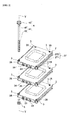
- Figure 2 is a partially exploded perspective view showing the battery pack 1 in the embodiment according to the present invention.
- Figure 3 is a perspective view of a unit cell 21 that is built into a battery module 2 in the embodiment according to the present invention;
- An assembled battery pack 1 in this embodiment includes a plurality of battery modules 2 stacked on one another and a through-bolt 4 for fixing by connecting the plurality of battery modules 2.
- Each battery module 2 as shown in Figures 2 and 3 , includes unit cells 21 stacked on to each other, a spacer 26 interposed between the unit cells 21, and a case for accommodating these unit cells 21 and spacers 26.
- the unit cell 21 is, for example, a laminate battery such as a lithium-ion secondary battery, and as shown in Figure 3 , of flat shape and includes a lamination body (not shown) obtained by stacking or laminating a positive electrode plate and a negative electrode plate alternately with a spacer interposed and a laminate film 211 that seals the lamination body with an electrolyte solution.
- a positive electrode tab 22 connected to the positive electrode plate is derived outside and a negative electrode tab 23 connected to the negative electrode is derived from the opposite end of the lamination film 211.
- the unit cell 21 may be composed of a nickel hydrogen battery , a lead battery and the like.
- FIG. 3 only two adjacent unit cells 21 are shown. However, in the actual case, eight unit cells 21 are stacked and accommodated in the case 27. Note that the number of unit cells 21 stacked in the case 27 is not particularly limited. For example, a single unit cell 21 may be contained in the case 27.
- the case 27, as shown in Figure 2 is composed of a lower case 271 and an upper case 272 of box shape. These lower case 271 and upper case 272 are formed, for example, of an aluminum plate.
- the cells 21, as shown in Figure 3 is placed in the lower case 271 in a state in which a spacer 26 is interposed for securing insulation of the unit cells 21 adjacent to each other , and, by covering the upper case 272 to lower case 271 , the cells 21 and the like are housed in the case 27.
- through-holes 28 are formed in the four corners of the case 27.
- the through-holes 28 are dimensioned in order for a shaft portion 41 of a through-bolt 4 described below may be inserted.
- an insertion auxiliary member 3 is attached in an opening 29 (see Figure 6 ) on the side of both the lower case 271 and the upper case 272. Note that the number of thorough holes 28 formed in the case 27 is not particularly limited.
- Figure 4 is a perspective view of the insertion auxiliary member 3 in the present embodiment.
- Figure 5 is a sectional view taken along line V-V in Figure 2 .
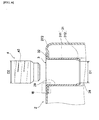
- Figure 6 is an enlarged view of the portion VI in Figure 5 ; and
- Figure 7 is an enlarged view of the portion VII in Figure 6 .
- the insertion auxiliary member 3, as shown in Figure 4 has an insertion portion 31 and an engaging portion 32, for example, is made of steel such as iron, stainless steel, etc., or formed from heat-resistant plastic resin.
- the insertion portion 31 includes a cylindrical portion 311 and a tapered portion 312.
- the cylindrical portion 311 has a cylindrical shape of an outer diameter slightly greater than the diameter of the through-hole 28, prior to a state of attachment to the opening 29 of the through-hole 28 formed in the battery module 2.
- the tapered portion 312 has an gradually decreasing inner diameter toward the tip or distal end, and is connected to a lower end of the cylindrical portion 311 in Figure 4 ..
- the engaging or locking portion 32 is provided in the insertion portion 31 coaxially and is formed to extend radially outward from the upper end of the insertion portion 31 in Figure 4 to resemble a flat doughnut.
- the insertion auxiliary member 3 is attached to the opening 29 of the through-hole 28 by press-fitting into the through-hole 28 after inserting the tapered portion 312 of the insertion portion 31 into the opening 29. At this time, as shown in Figure 6 , the engaging portion 32 is engaged with the peripheral edge of the opening 29 of the through-hole 28 and the insertion auxiliary member 3 will be held in the opening 29.
- the insertion auxiliary member is formed radially deformable.
- the shape of the slit 33 is not limited to the one which is described above. Also, the way by which the insertion auxiliary member 3slits 33 is made deformable is not particularly limited.
- the manufacturing method is not limited thereto.
- the manufacturing method is not limited thereto. For example, after forming the insertion portion 31 and the engaging portion 32 separately, these are then joined to form the insertion auxiliary member 3.
- the insertion auxiliary member 3 in the present embodiment is attached to both the top and the bottom of the openings 29 of the through-hole 28, the arrangement is not particularly limited thereto.
- the insertion auxiliary member 3 may be attached to the one of the upper or lower openings 29 of the through-holes 28.
- the insertion auxiliary member 3 in the present embodiment has a tapered portion 322 on the inner side of the engaging portion 32, that increases in the inner diameter gradually toward the top surface 321 of the engaging portion 32.
- the through-bolt 4 connecting the battery modules 2, as shown in Figure 2 includes a head portion 40 and a shaft portion 41.
- the shaft portion 41 is formed with a screw or threaded portion 42 to be screwed with the nut 5 and a cylindrical portion 43 with an appropriate dimensioned so as to be insertable into the cylindrical portion 311 of the insertion auxiliary member 3 fitted into the opening 29 of the through-hole 28. Further, the length of the shaft portion 41 is set slightly longer than the length of the plurality of battery modules 2 of the battery pack 1 in the stacking direction.
- the through-bolt 4, as shown in Figure 2 after being inserted through each of the four through-holes 28 formed in the case 27 of each battery module 2, by fastening with a nut 5, the plurality of battery modules 2 are connected and fixed to each other.
- FIG 2 only three battery modules 2 are shown, and the remaining stacked battery modules 2 are omitted.
- Figure 2 only one of four through-bolts 4 is shown, which are respectively inserted into four through-holes 28 formed with the case 27 of the battery modules 2, and the remaining three through-bolts are omitted.
- the threaded portion 42 of the through-bolt 4 in the present embodiment has a larger diameter of D2 than the minimum value D1 of the inner diameter provided at the tapered portion 312 of the insertion auxiliary member 3 attached to the opening 29 of the through-hole 28 (D2> D1).
- the threaded portion 42 may be formed smaller than the cylindrical portion 43 so that the cylindrical portion 43 has a diameter D2.
- both the threaded portion 42 and the cylindrical portion 43 may have the diameter D2.
- a through-bolt 4 is inserted through the through-holes 28 respectively provided to a plurality of cases 27 of the stacked battery modules 2. Thereafter, by fastening with a nut 5, the plurality of battery modules are connected and fixed together.
- the insertion auxiliary member 3 is attached to the opening 29 of the through-hole 28, and in the periphery of the lower end of the insertion portion 31 of the insertion auxiliary member 3, a tapered portion 312 is provided which decreases it inner diameter gradually toward its tip.
- the through-bolt 4 pressurized the insertion auxiliary member 3 in the radial direction via the inclination of the tapered portion 312 so that the position of the battery module 2 will be modified to be located near the center of the through-hole 28.
- the through-bolt 4 may be inserted with ease into the through-holes 28 of the plurality of battery modules 2. Therefore, it is possible to improve the assembly workability of the battery pack 1.
- the insertion auxiliary member 3 is attached to both the upper side and lower side openings 29. Therefore, irrespective in which direction, i.e., from the upper side or lower side, the though bolt 4 is inserted, it is possible to improve the assembly workability of the assembled battery 1.
- a slit 33 is formed such that the insertion auxiliary member 3 is resiliently deformable in the radial direction. Therefore, when the insertion auxiliary member 3 is attached by press-fitting in the opening 29 of the through-hole 28, the insertion auxiliary member 3 can be stably maintained in the opening 29.
- the insertion auxiliary member 3 being elastically deformable in the radial direction by the slit 33, when the thorough bolt 4 is inserted along the shape of the tapered portion 312, it is possible to reduce a play between the through-bolt 4 and the tapered portion312. Therefore, it is possible that the alignment accuracy of the battery modules 2 at the time of insertion of the through-bolts 4 is improved, and further, the assembly work of battery pack 1 will be improved.
- the threaded portion 42 of the through-bolt 4 in the present embodiment is configured to have a diameter D2 larger than the minimum value D1 of the inner diameter of the tapered portion 312 of the insertion auxiliary member 3 attached to the opening 29 of the through-hole 28 (D2> D1).
- the insertion auxiliary member 3 in the present embodiment is provided with a tapered portion 322 on the inner side of the engaging portion 32, whose inner diameter gradually increases toward the top or upper surface 321 of the engaging portion 32. Therefore, even when the through-bolt 4 is about to be inserted slightly deviated from the opening 29 of the through-hole 28, since the through-bolt 4 may be inserted into the through-hole 28 along the shape of the tapered portion 322 the workability in the insertion work of the through-bolt 4 can be improved.
- the through-bolt 4 when being pressed into the through-hole 28, pressurizes the insertion auxiliary member 3 radially via the inclination of thee tapered portion 322.
- the position of the battery modules 2 will be corrected so that the through-bolt 4 will be positioned near the center of the through-hole 28.
- the position deviation tolerance of the battery modules 2 allowed at the time of insertion of the though bolt 4 is expanded so as for the through-bolt 4 to be more easily inserted. Therefore, the assembly workability of the battery pack 1 will be even more improved.
- the case 27 in the present embodiment corresponds to an example of a housing according to the present invention.
- the insertion auxiliary member 3 in the present embodiment corresponds to an example of a tubular member in the present invention.
- the lower end of the insertion portion 31 of the insertion auxiliary member 3 in this embodiment corresponds to an example of a tip of the tubular member in the present invention.
- Thee tapered portion 312 in this embodiment corresponds to an example of a first tapered portion in the present invention.
- the diameter D2 of the threaded portion 42 of the through-bolt 4 in this embodiment corresponds to an example of the maximum outer diameter of the shaft portion of the bolt in the present invention.
- the minimum internal diameter value D1 of the inner diameter of the tapered portion 312 in this embodiment corresponds to the minimum internal diameter of the first tapered portion of the present invention
- the top surface 321 of the engaging portion 32 of the insertion auxiliary member 3 in the present embodiment corresponds to an example of the rear end of the tubular member.
- the tapered portion 322 in the present embodiment corresponds to an example of a second tapered portion in the present invention.
Landscapes
- Chemical & Material Sciences (AREA)
- Chemical Kinetics & Catalysis (AREA)
- Electrochemistry (AREA)
- General Chemical & Material Sciences (AREA)
- Engineering & Computer Science (AREA)
- Manufacturing & Machinery (AREA)
- Battery Mounting, Suspending (AREA)
- Connection Of Batteries Or Terminals (AREA)
Abstract
Description
- The present invention relates to a battery pack comprising a plurality of battery modules. This application claims priority based on Japanese Patent Application No.
2012-205738 filed on September 19, 2012 - An assembled battery pack is known, that combines a plurality of small battery packs by passing a through-bolt in a hole provided in the frame of a battery pack spacer for flat batteries. (for example, see Patent Document 1).
- Patent Document 1: Japanese Patent Application Publication No.
JP 2009-272234 A - In the above battery pack, at the increase of the number of stacking or laminations, when the small battery packs are deviated even slightly, a problem arises that the through-bolt is difficult to be inserted into the hole and thus the assembly workability will be decreased.
- The object to be attained is to provide a battery pack with improved assembly workability.
- The present invention solves the problem described above by inserting a tubular or cylindrical member having a first tapered portion with a progressively smaller inner diameter toward its tip into at least one end portion of a through-hole formed in a housing of an electric module along the stacking direction of the battery modules.
- According to the present invention, when inserting a bolt into the through-hole of the battery module, since the insertion position of the bolt is corrected in the vicinity of the center of the through-hole by the first tapered portion, it is possible to improve the assembly workability of the battery pack.
-
-
Figure 1 is a perspective view of a battery pack in an embodiment according to the present invention; -
Figure 2 is a partially exploded perspective view showing the battery pack in the embodiment according to the present invention; -
Figure 3 is a perspective view of a unit cell that is built into a battery module in the embodiment according to the present invention; -
Figure 4 is a perspective view of an insertion auxiliary member in the embodiment according to the present invention; -
Figure 5 is a sectional view taken along line V-V inFigure 2 ; -
Figure 6 is an enlarged view of the portion VI inFigure 5 ; and -
Figure 7 is an enlarged view of the portion VII inFigure 6 . - Below, a description is given of the present embodiment with reference to the drawings.
-
Figure 1 is a perspective view of a battery pack 1 in an embodiment according to the present invention.Figure 2 is a partially exploded perspective view showing the battery pack 1 in the embodiment according to the present invention.Figure 3 is a perspective view of aunit cell 21 that is built into abattery module 2 in the embodiment according to the present invention; - An assembled battery pack 1 in this embodiment, as shown in
Figure 1 , includes a plurality ofbattery modules 2 stacked on one another and a through-bolt 4 for fixing by connecting the plurality ofbattery modules 2. - Each
battery module 2, as shown inFigures 2 and3 , includesunit cells 21 stacked on to each other, aspacer 26 interposed between theunit cells 21, and a case for accommodating theseunit cells 21 andspacers 26. - The
unit cell 21 is, for example, a laminate battery such as a lithium-ion secondary battery, and as shown inFigure 3 , of flat shape and includes a lamination body (not shown) obtained by stacking or laminating a positive electrode plate and a negative electrode plate alternately with a spacer interposed and alaminate film 211 that seals the lamination body with an electrolyte solution. Apositive electrode tab 22 connected to the positive electrode plate is derived outside and anegative electrode tab 23 connected to the negative electrode is derived from the opposite end of thelamination film 211. Note that theunit cell 21 may be composed of a nickel hydrogen battery , a lead battery and the like. - In the present embodiment, as shown in
Figure 3 , after stacking theunit cells 21 by reversing thepositive electrode tab 22 and the negative electrode tab alternately, by connecting the positive electrode tab and the negative electrode tab directly,respective unit cells 21 are connected in series. Further, a positive electrodeside output terminal 24 is electrically connected to one end of a plurality ofunit cells 21 electrically connected to each other, and a negative electrodeside output terminal 25 is electrically connected to the other end. Note that the electrical connection of the unit cells is not particularly limited thereto. - Incidentally, in
Figure 3 , only twoadjacent unit cells 21 are shown. However, in the actual case, eightunit cells 21 are stacked and accommodated in thecase 27. Note that the number ofunit cells 21 stacked in thecase 27 is not particularly limited. For example, asingle unit cell 21 may be contained in thecase 27. - The
case 27, as shown inFigure 2 , is composed of alower case 271 and anupper case 272 of box shape. Theselower case 271 andupper case 272 are formed, for example, of an aluminum plate. - The
cells 21, as shown inFigure 3 , is placed in thelower case 271 in a state in which aspacer 26 is interposed for securing insulation of theunit cells 21 adjacent to each other , and, by covering theupper case 272 tolower case 271 , thecells 21 and the like are housed in thecase 27. - In the present embodiment, as shown in
Figure 2 , through-holes 28 are formed in the four corners of thecase 27. The through-holes 28 are dimensioned in order for ashaft portion 41 of a through-bolt 4 described below may be inserted. Further, in each of the through-holes 28, an insertionauxiliary member 3 is attached in an opening 29 (seeFigure 6 ) on the side of both thelower case 271 and theupper case 272. Note that the number ofthorough holes 28 formed in thecase 27 is not particularly limited. -
Figure 4 is a perspective view of the insertionauxiliary member 3 in the present embodiment.Figure 5 is a sectional view taken along line V-V inFigure 2 .
Figure 6 is an enlarged view of the portion VI inFigure 5 ; andFigure 7 is an enlarged view of the portion VII inFigure 6 . - The insertion
auxiliary member 3, as shown inFigure 4 , has aninsertion portion 31 and anengaging portion 32, for example, is made of steel such as iron, stainless steel, etc., or formed from heat-resistant plastic resin. - The
insertion portion 31 includes acylindrical portion 311 and atapered portion 312. Thecylindrical portion 311 has a cylindrical shape of an outer diameter slightly greater than the diameter of the through-hole 28, prior to a state of attachment to the opening 29 of the through-hole 28 formed in thebattery module 2. On the other hand, thetapered portion 312 has an gradually decreasing inner diameter toward the tip or distal end, and is connected to a lower end of thecylindrical portion 311 inFigure 4 .. - The engaging or locking
portion 32 is provided in theinsertion portion 31 coaxially and is formed to extend radially outward from the upper end of theinsertion portion 31 inFigure 4 to resemble a flat doughnut. - The insertion
auxiliary member 3 is attached to the opening 29 of the through-hole 28 by press-fitting into the through-hole 28 after inserting thetapered portion 312 of theinsertion portion 31 into the opening 29. At this time, as shown inFigure 6 , theengaging portion 32 is engaged with the peripheral edge of the opening 29 of the through-hole 28 and the insertionauxiliary member 3 will be held in the opening 29. - A part of the side surface of the insertion
auxiliary member 3 in the present embodiment, as shown inFigure 3 , is formed with aslit 33 substantially parallel to the axial direction of the insertionauxiliary member 3. Thus, the insertion auxiliary member is formed radially deformable. Note that the shape of theslit 33 is not limited to the one which is described above. Also, the way by which the insertionauxiliary member 3slits 33 is made deformable is not particularly limited. - In the present embodiment, although the
insertion portion 31 and the locking orengaging portion 32 are integrally formed by pressing a single steel material, the manufacturing method is not limited thereto. For example, after forming theinsertion portion 31 and theengaging portion 32 separately, these are then joined to form the insertionauxiliary member 3. - In addition, although the insertion
auxiliary member 3 in the present embodiment, as shown inFigure 5 , is attached to both the top and the bottom of theopenings 29 of the through-hole 28, the arrangement is not particularly limited thereto. Theinsertion auxiliary member 3 may be attached to the one of the upper orlower openings 29 of the through-holes 28. - Also, the
insertion auxiliary member 3 in the present embodiment, as shown inFigure 7 , has a taperedportion 322 on the inner side of the engagingportion 32, that increases in the inner diameter gradually toward thetop surface 321 of the engagingportion 32. - The through-
bolt 4 connecting thebattery modules 2, as shown inFigure 2 , includes ahead portion 40 and ashaft portion 41. - The
shaft portion 41 is formed with a screw or threadedportion 42 to be screwed with the nut 5 and acylindrical portion 43 with an appropriate dimensioned so as to be insertable into thecylindrical portion 311 of theinsertion auxiliary member 3 fitted into theopening 29 of the through-hole 28. Further, the length of theshaft portion 41 is set slightly longer than the length of the plurality ofbattery modules 2 of the battery pack 1 in the stacking direction. - The through-
bolt 4, as shown inFigure 2 , after being inserted through each of the four through-holes 28 formed in thecase 27 of eachbattery module 2, by fastening with a nut 5, the plurality ofbattery modules 2 are connected and fixed to each other. InFigure 2 , only threebattery modules 2 are shown, and the remainingstacked battery modules 2 are omitted. Also, inFigure 2 , only one of four through-bolts 4 is shown, which are respectively inserted into four through-holes 28 formed with thecase 27 of thebattery modules 2, and the remaining three through-bolts are omitted. - The threaded
portion 42 of the through-bolt 4 in the present embodiment, as shown inFigure 6 , has a larger diameter of D2 than the minimum value D1 of the inner diameter provided at the taperedportion 312 of theinsertion auxiliary member 3 attached to theopening 29 of the through-hole 28 (D2> D1). Alternatively, the threadedportion 42 may be formed smaller than thecylindrical portion 43 so that thecylindrical portion 43 has a diameter D2. Further, both the threadedportion 42 and thecylindrical portion 43 may have the diameter D2. - Now, a description is give of the operation of the present embodiment.
- In the assembled battery pack 1 in the present embodiment, as shown in
Figures 1 and2 , a through-bolt 4 is inserted through the through-holes 28 respectively provided to a plurality ofcases 27 of the stackedbattery modules 2. Thereafter, by fastening with a nut 5, the plurality of battery modules are connected and fixed together. - When assembling the battery pack 1, as shown in
Figure 2 , an approximate positioning of the plurality ofbattery modules 2 is performed so that the through-holes 28 will be aligned with each other with eachbattery module 2 overlapping, then the through-bolt 4 is sequentially inserted in the through-hole 28 of each of thebattery modules 2. - In the present embodiment, as shown in
Figure 6 , theinsertion auxiliary member 3 is attached to theopening 29 of the through-hole 28, and in the periphery of the lower end of theinsertion portion 31 of theinsertion auxiliary member 3, a taperedportion 312 is provided which decreases it inner diameter gradually toward its tip. Thus, at the time of insertion of the through-bolt 4, when the through-bolt 4 is pushed into the through-hole 28, the through-bolt 4 pressurized theinsertion auxiliary member 3 in the radial direction via the inclination of the taperedportion 312 so that the position of thebattery module 2 will be modified to be located near the center of the through-hole 28. - Thus, at the time of insertion of the through-
bolt 4, even though a slight misalignment among the plurality of battery modules is caused, the through-bolt 4 may be inserted with ease into the through-holes 28 of the plurality ofbattery modules 2. Therefore, it is possible to improve the assembly workability of the battery pack 1. - In the present embodiment, as shown in
Figure 5 , theinsertion auxiliary member 3 is attached to both the upper side andlower side openings 29. Therefore, irrespective in which direction, i.e., from the upper side or lower side, the thoughbolt 4 is inserted, it is possible to improve the assembly workability of the assembled battery 1. - Furthermore, on the side of the
insertion auxiliary member 3 in the present embodiment, as shown inFigure 4 , aslit 33 is formed such that theinsertion auxiliary member 3 is resiliently deformable in the radial direction. Therefore, when theinsertion auxiliary member 3 is attached by press-fitting in theopening 29 of the through-hole 28, theinsertion auxiliary member 3 can be stably maintained in theopening 29. - Moreover, due to the
insertion auxiliary member 3 being elastically deformable in the radial direction by theslit 33, when thethorough bolt 4 is inserted along the shape of the taperedportion 312, it is possible to reduce a play between the through-bolt 4 and the tapered portion312. Therefore, it is possible that the alignment accuracy of thebattery modules 2 at the time of insertion of the through-bolts 4 is improved, and further, the assembly work of battery pack 1 will be improved. - Also, the threaded
portion 42 of the through-bolt 4 in the present embodiment, as shown inFigure 6 , is configured to have a diameter D2 larger than the minimum value D1 of the inner diameter of the taperedportion 312 of theinsertion auxiliary member 3 attached to theopening 29 of the through-hole 28 (D2> D1). With the play further reduced between the through-bolt 4 and the taperedportion 312 when the through-bolt is inserted along the shape of the taperedportion 312, the position alignment accuracy of thebattery modules 2 at the time of insertion of the through-bolt 4 will be further improved so that it is possible to further improve the assembly workability of the assembled battery pack 1. - Also, the
insertion auxiliary member 3 in the present embodiment, as shown inFigure 7 , is provided with a taperedportion 322 on the inner side of the engagingportion 32, whose inner diameter gradually increases toward the top orupper surface 321 of the engagingportion 32. Therefore, even when the through-bolt 4 is about to be inserted slightly deviated from theopening 29 of the through-hole 28, since the through-bolt 4 may be inserted into the through-hole 28 along the shape of the taperedportion 322 the workability in the insertion work of the through-bolt 4 can be improved. - Furthermore, even when the positional deviation between the
battery modules 2 has occurred at the time of insertion of the through-bolt 4, the through-bolt 4, when being pressed into the through-hole 28, pressurizes theinsertion auxiliary member 3 radially via the inclination of thee taperedportion 322. Thus, the position of thebattery modules 2 will be corrected so that the through-bolt 4 will be positioned near the center of the through-hole 28. Thus, the position deviation tolerance of thebattery modules 2 allowed at the time of insertion of the thoughbolt 4 is expanded so as for the through-bolt 4 to be more easily inserted. Therefore, the assembly workability of the battery pack 1 will be even more improved. - The
case 27 in the present embodiment corresponds to an example of a housing according to the present invention. Theinsertion auxiliary member 3 in the present embodiment corresponds to an example of a tubular member in the present invention. The lower end of theinsertion portion 31 of theinsertion auxiliary member 3 in this embodiment corresponds to an example of a tip of the tubular member in the present invention. Thee taperedportion 312 in this embodiment corresponds to an example of a first tapered portion in the present invention. The diameter D2 of the threadedportion 42 of the through-bolt 4 in this embodiment corresponds to an example of the maximum outer diameter of the shaft portion of the bolt in the present invention. The minimum internal diameter value D1 of the inner diameter of the taperedportion 312 in this embodiment corresponds to the minimum internal diameter of the first tapered portion of the present invention Thetop surface 321 of the engagingportion 32 of theinsertion auxiliary member 3 in the present embodiment corresponds to an example of the rear end of the tubular member. Finally, the taperedportion 322 in the present embodiment corresponds to an example of a second tapered portion in the present invention. - The embodiments described above is a one that is described in order to facilitate understanding of the invention and are not to those described to limit the present invention. Therefore, the elements disclosed in the above embodiments are intended to include all design modifications and equivalents belonging to the technical scope of the present invention.
-
- 1
- battery pack
- 2
- battery module
- 21
- single battery
- 27
- case
- 28
- through-hole
- 3
- insertion auxiliary member
- 311
- tapered portion
- 322
- tapered portion
- 4
- through-bolt
Claims (5)
- A battery pack, comprising:a plurality of battery modules stacked to each other, each being provided with a housing accommodating a unit cell;a bolt that is inserted into a through-hole formed in the housing along the stacking direction of the batter modules to connect the battery modules each other, wherein the battery module has a tubular member that is inserted at least one end of the through-hole, and the tubular member has a first tapered portion whose inner diameter decreases gradually toward the tip of the tubular member.
- A battery pack according to claim 1, wherein the tubular member is inserted into both openings of the through-hole.
- A battery pack according to either claim 1 or 2, wherein the tubular member is elastically deformable at least in the radial direction of the tubular member.
- A battery pack according to any one of claims 1 to 3, wherein the maximum outer diameter of the shaft portion of the bolt is configured to be greater than the minimum value of the inner diameter of the first tapered portion.
- A battery pack according to any one of claims 1 to 4, wherein the tubular member has a second tapered portion whose inner diameter gradually increases toward the rear end of the tubular member.
Applications Claiming Priority (2)
| Application Number | Priority Date | Filing Date | Title |
|---|---|---|---|
| JP2012205738 | 2012-09-19 | ||
| PCT/JP2013/071619 WO2014045757A1 (en) | 2012-09-19 | 2013-08-09 | Battery assembly |
Publications (3)
| Publication Number | Publication Date |
|---|---|
| EP2899772A1 true EP2899772A1 (en) | 2015-07-29 |
| EP2899772A4 EP2899772A4 (en) | 2015-09-23 |
| EP2899772B1 EP2899772B1 (en) | 2018-06-06 |
Family
ID=50341081
Family Applications (1)
| Application Number | Title | Priority Date | Filing Date |
|---|---|---|---|
| EP13839446.5A Active EP2899772B1 (en) | 2012-09-19 | 2013-08-09 | Battery assembly |
Country Status (6)
| Country | Link |
|---|---|
| US (1) | US9478775B2 (en) |
| EP (1) | EP2899772B1 (en) |
| JP (1) | JP6020575B2 (en) |
| KR (1) | KR101788944B1 (en) |
| CN (1) | CN104521026B (en) |
| WO (1) | WO2014045757A1 (en) |
Families Citing this family (11)
| Publication number | Priority date | Publication date | Assignee | Title |
|---|---|---|---|---|
| JP5832819B2 (en) * | 2011-08-18 | 2015-12-16 | 大和製罐株式会社 | Assembled battery |
| USD765594S1 (en) * | 2015-05-22 | 2016-09-06 | Shenzhen Innokin Technology Co., Limited. | Battery |
| JP2018190486A (en) * | 2015-09-29 | 2018-11-29 | パナソニックIpマネジメント株式会社 | Battery module |
| KR102066197B1 (en) * | 2015-12-09 | 2020-01-14 | 주식회사 엘지화학 | Battery module and battery pack including the same |
| JP6801208B2 (en) * | 2016-03-25 | 2020-12-16 | 株式会社豊田自動織機 | Battery module |
| JP2019002496A (en) * | 2017-06-16 | 2019-01-10 | 日産自動車株式会社 | Shaft member insertion structure |
| JP7020804B2 (en) * | 2017-06-19 | 2022-02-16 | 本田技研工業株式会社 | Battery pack |
| JP7264266B2 (en) * | 2019-10-10 | 2023-04-25 | 株式会社村田製作所 | secondary battery |
| KR102916838B1 (en) * | 2019-12-13 | 2026-01-22 | 현대자동차주식회사 | Vehicle body member having charger and discharger function |
| JP7676930B2 (en) * | 2021-05-17 | 2025-05-15 | トヨタ自動車株式会社 | Battery pack |
| CN115241594B (en) * | 2022-07-26 | 2024-04-09 | 浙江浙能嘉华发电有限公司 | Robot for power plant inspection |
Family Cites Families (15)
| Publication number | Priority date | Publication date | Assignee | Title |
|---|---|---|---|---|
| JPH0315853Y2 (en) * | 1986-11-04 | 1991-04-05 | ||
| JPS6393275U (en) * | 1986-12-10 | 1988-06-16 | ||
| JP3897029B2 (en) * | 2004-03-30 | 2007-03-22 | 日産自動車株式会社 | Battery frame and battery pack |
| JP4848733B2 (en) | 2004-10-22 | 2011-12-28 | 日産自動車株式会社 | Battery module and battery pack |
| JP4992244B2 (en) * | 2005-04-07 | 2012-08-08 | 日産自動車株式会社 | Battery module and battery pack |
| JP4770489B2 (en) * | 2006-01-31 | 2011-09-14 | トヨタ自動車株式会社 | Electrode laminate and bipolar secondary battery |
| JP5078349B2 (en) * | 2006-12-29 | 2012-11-21 | 三洋電機株式会社 | Pack battery |
| JP5343368B2 (en) | 2008-02-28 | 2013-11-13 | 日産自動車株式会社 | Battery module fixing structure and battery module fixing method |
| JP5146092B2 (en) | 2008-05-09 | 2013-02-20 | 株式会社Gsユアサ | Battery assembly spacer and battery assembly using the same |
| JP2010014233A (en) * | 2008-07-04 | 2010-01-21 | Shimizu Corp | Post bolt joint structure and post joint member |
| JP5504724B2 (en) * | 2009-07-17 | 2014-05-28 | 日産自動車株式会社 | Battery pack and manufacturing method thereof |
| JP5415209B2 (en) * | 2009-09-30 | 2014-02-12 | 日産自動車株式会社 | Battery module and battery module group manufacturing method |
| JP5359855B2 (en) * | 2009-12-25 | 2013-12-04 | 株式会社豊田自動織機 | Battery fixing device |
| JP5626852B2 (en) | 2010-05-19 | 2014-11-19 | Necエナジーデバイス株式会社 | Power supply |
| CN202134614U (en) * | 2011-06-07 | 2012-02-01 | 肇庆理士电源技术有限公司 | Storage battery mould box locking mechanism |
-
2013
- 2013-08-09 CN CN201380041249.0A patent/CN104521026B/en active Active
- 2013-08-09 WO PCT/JP2013/071619 patent/WO2014045757A1/en not_active Ceased
- 2013-08-09 JP JP2014536676A patent/JP6020575B2/en active Active
- 2013-08-09 EP EP13839446.5A patent/EP2899772B1/en active Active
- 2013-08-09 US US14/424,644 patent/US9478775B2/en active Active
- 2013-08-09 KR KR1020157004765A patent/KR101788944B1/en active Active
Also Published As
| Publication number | Publication date |
|---|---|
| EP2899772A4 (en) | 2015-09-23 |
| US9478775B2 (en) | 2016-10-25 |
| US20150221907A1 (en) | 2015-08-06 |
| WO2014045757A1 (en) | 2014-03-27 |
| KR101788944B1 (en) | 2017-10-20 |
| JP6020575B2 (en) | 2016-11-02 |
| CN104521026B (en) | 2017-07-07 |
| JPWO2014045757A1 (en) | 2016-08-18 |
| EP2899772B1 (en) | 2018-06-06 |
| KR20150038304A (en) | 2015-04-08 |
| CN104521026A (en) | 2015-04-15 |
Similar Documents
| Publication | Publication Date | Title |
|---|---|---|
| EP2899772B1 (en) | Battery assembly | |
| JP6752674B2 (en) | Battery pack | |
| JP5490516B2 (en) | Battery pack | |
| EP2432048B1 (en) | Stacked cell and method for manufacturing same | |
| EP2562842B1 (en) | Battery module | |
| EP2793290B1 (en) | Battery module | |
| US8623540B2 (en) | Rechargeable battery and rechargeable battery module | |
| JP5415209B2 (en) | Battery module and battery module group manufacturing method | |
| EP4254646A1 (en) | Insulating support and battery module | |
| KR101153957B1 (en) | Electrode tab assembly for secondary battery and assembling methode of the same | |
| KR102210461B1 (en) | Battery module comprising a unit battery module and battery pack comprisng the same and Method of manufacturing the battery module | |
| EP3926741A1 (en) | End cap assembly, battery cell, battery module, and apparatus | |
| JP5343368B2 (en) | Battery module fixing structure and battery module fixing method | |
| JP2011253779A (en) | Battery pack | |
| EP2899773B1 (en) | Assembled battery | |
| JP2011249250A (en) | Battery pack | |
| CN217114627U (en) | Battery and electric device | |
| KR20160004545A (en) | Jig Having Mounting Grooves and Protrusions for Assembling Battery Cells | |
| US10461290B2 (en) | Electric storage apparatus, and method for producing electric storage apparatus | |
| JP2014127366A (en) | Module battery | |
| US20220109209A1 (en) | Battery module and manufacturing method of battery module | |
| KR102915631B1 (en) | Battery module including busbar frame separated from top and bottom and assembly method having the same | |
| CN221379624U (en) | Energy storage device and electrical equipment | |
| WO2019221223A1 (en) | Battery pack | |
| CN119994363A (en) | Energy storage device and electrical equipment |
Legal Events
| Date | Code | Title | Description |
|---|---|---|---|
| PUAI | Public reference made under article 153(3) epc to a published international application that has entered the european phase |
Free format text: ORIGINAL CODE: 0009012 |
|
| 17P | Request for examination filed |
Effective date: 20150113 |
|
| AK | Designated contracting states |
Kind code of ref document: A1 Designated state(s): AL AT BE BG CH CY CZ DE DK EE ES FI FR GB GR HR HU IE IS IT LI LT LU LV MC MK MT NL NO PL PT RO RS SE SI SK SM TR |
|
| AX | Request for extension of the european patent |
Extension state: BA ME |
|
| RA4 | Supplementary search report drawn up and despatched (corrected) |
Effective date: 20150826 |
|
| RIC1 | Information provided on ipc code assigned before grant |
Ipc: H01M 10/04 20060101ALI20150820BHEP Ipc: H01M 2/10 20060101AFI20150820BHEP |
|
| DAX | Request for extension of the european patent (deleted) | ||
| 17Q | First examination report despatched |
Effective date: 20170810 |
|
| GRAP | Despatch of communication of intention to grant a patent |
Free format text: ORIGINAL CODE: EPIDOSNIGR1 |
|
| INTG | Intention to grant announced |
Effective date: 20180119 |
|
| INTG | Intention to grant announced |
Effective date: 20180119 |
|
| GRAS | Grant fee paid |
Free format text: ORIGINAL CODE: EPIDOSNIGR3 |
|
| GRAA | (expected) grant |
Free format text: ORIGINAL CODE: 0009210 |
|
| AK | Designated contracting states |
Kind code of ref document: B1 Designated state(s): AL AT BE BG CH CY CZ DE DK EE ES FI FR GB GR HR HU IE IS IT LI LT LU LV MC MK MT NL NO PL PT RO RS SE SI SK SM TR |
|
| REG | Reference to a national code |
Ref country code: GB Ref legal event code: FG4D |
|
| REG | Reference to a national code |
Ref country code: CH Ref legal event code: EP Ref country code: AT Ref legal event code: REF Ref document number: 1007023 Country of ref document: AT Kind code of ref document: T Effective date: 20180615 |
|
| REG | Reference to a national code |
Ref country code: IE Ref legal event code: FG4D |
|
| REG | Reference to a national code |
Ref country code: DE Ref legal event code: R096 Ref document number: 602013038675 Country of ref document: DE |
|
| REG | Reference to a national code |
Ref country code: FR Ref legal event code: PLFP Year of fee payment: 6 |
|
| REG | Reference to a national code |
Ref country code: NL Ref legal event code: MP Effective date: 20180606 |
|
| REG | Reference to a national code |
Ref country code: LT Ref legal event code: MG4D |
|
| PG25 | Lapsed in a contracting state [announced via postgrant information from national office to epo] |
Ref country code: CY Free format text: LAPSE BECAUSE OF FAILURE TO SUBMIT A TRANSLATION OF THE DESCRIPTION OR TO PAY THE FEE WITHIN THE PRESCRIBED TIME-LIMIT Effective date: 20180606 Ref country code: LT Free format text: LAPSE BECAUSE OF FAILURE TO SUBMIT A TRANSLATION OF THE DESCRIPTION OR TO PAY THE FEE WITHIN THE PRESCRIBED TIME-LIMIT Effective date: 20180606 Ref country code: SE Free format text: LAPSE BECAUSE OF FAILURE TO SUBMIT A TRANSLATION OF THE DESCRIPTION OR TO PAY THE FEE WITHIN THE PRESCRIBED TIME-LIMIT Effective date: 20180606 Ref country code: NO Free format text: LAPSE BECAUSE OF FAILURE TO SUBMIT A TRANSLATION OF THE DESCRIPTION OR TO PAY THE FEE WITHIN THE PRESCRIBED TIME-LIMIT Effective date: 20180906 Ref country code: ES Free format text: LAPSE BECAUSE OF FAILURE TO SUBMIT A TRANSLATION OF THE DESCRIPTION OR TO PAY THE FEE WITHIN THE PRESCRIBED TIME-LIMIT Effective date: 20180606 Ref country code: BG Free format text: LAPSE BECAUSE OF FAILURE TO SUBMIT A TRANSLATION OF THE DESCRIPTION OR TO PAY THE FEE WITHIN THE PRESCRIBED TIME-LIMIT Effective date: 20180906 Ref country code: FI Free format text: LAPSE BECAUSE OF FAILURE TO SUBMIT A TRANSLATION OF THE DESCRIPTION OR TO PAY THE FEE WITHIN THE PRESCRIBED TIME-LIMIT Effective date: 20180606 |
|
| PG25 | Lapsed in a contracting state [announced via postgrant information from national office to epo] |
Ref country code: LV Free format text: LAPSE BECAUSE OF FAILURE TO SUBMIT A TRANSLATION OF THE DESCRIPTION OR TO PAY THE FEE WITHIN THE PRESCRIBED TIME-LIMIT Effective date: 20180606 Ref country code: RS Free format text: LAPSE BECAUSE OF FAILURE TO SUBMIT A TRANSLATION OF THE DESCRIPTION OR TO PAY THE FEE WITHIN THE PRESCRIBED TIME-LIMIT Effective date: 20180606 Ref country code: GR Free format text: LAPSE BECAUSE OF FAILURE TO SUBMIT A TRANSLATION OF THE DESCRIPTION OR TO PAY THE FEE WITHIN THE PRESCRIBED TIME-LIMIT Effective date: 20180907 Ref country code: HR Free format text: LAPSE BECAUSE OF FAILURE TO SUBMIT A TRANSLATION OF THE DESCRIPTION OR TO PAY THE FEE WITHIN THE PRESCRIBED TIME-LIMIT Effective date: 20180606 |
|
| REG | Reference to a national code |
Ref country code: AT Ref legal event code: MK05 Ref document number: 1007023 Country of ref document: AT Kind code of ref document: T Effective date: 20180606 |
|
| PG25 | Lapsed in a contracting state [announced via postgrant information from national office to epo] |
Ref country code: NL Free format text: LAPSE BECAUSE OF FAILURE TO SUBMIT A TRANSLATION OF THE DESCRIPTION OR TO PAY THE FEE WITHIN THE PRESCRIBED TIME-LIMIT Effective date: 20180606 |
|
| PG25 | Lapsed in a contracting state [announced via postgrant information from national office to epo] |
Ref country code: AT Free format text: LAPSE BECAUSE OF FAILURE TO SUBMIT A TRANSLATION OF THE DESCRIPTION OR TO PAY THE FEE WITHIN THE PRESCRIBED TIME-LIMIT Effective date: 20180606 Ref country code: IS Free format text: LAPSE BECAUSE OF FAILURE TO SUBMIT A TRANSLATION OF THE DESCRIPTION OR TO PAY THE FEE WITHIN THE PRESCRIBED TIME-LIMIT Effective date: 20181006 Ref country code: PL Free format text: LAPSE BECAUSE OF FAILURE TO SUBMIT A TRANSLATION OF THE DESCRIPTION OR TO PAY THE FEE WITHIN THE PRESCRIBED TIME-LIMIT Effective date: 20180606 Ref country code: SK Free format text: LAPSE BECAUSE OF FAILURE TO SUBMIT A TRANSLATION OF THE DESCRIPTION OR TO PAY THE FEE WITHIN THE PRESCRIBED TIME-LIMIT Effective date: 20180606 Ref country code: EE Free format text: LAPSE BECAUSE OF FAILURE TO SUBMIT A TRANSLATION OF THE DESCRIPTION OR TO PAY THE FEE WITHIN THE PRESCRIBED TIME-LIMIT Effective date: 20180606 Ref country code: CZ Free format text: LAPSE BECAUSE OF FAILURE TO SUBMIT A TRANSLATION OF THE DESCRIPTION OR TO PAY THE FEE WITHIN THE PRESCRIBED TIME-LIMIT Effective date: 20180606 Ref country code: RO Free format text: LAPSE BECAUSE OF FAILURE TO SUBMIT A TRANSLATION OF THE DESCRIPTION OR TO PAY THE FEE WITHIN THE PRESCRIBED TIME-LIMIT Effective date: 20180606 |
|
| PG25 | Lapsed in a contracting state [announced via postgrant information from national office to epo] |
Ref country code: SM Free format text: LAPSE BECAUSE OF FAILURE TO SUBMIT A TRANSLATION OF THE DESCRIPTION OR TO PAY THE FEE WITHIN THE PRESCRIBED TIME-LIMIT Effective date: 20180606 Ref country code: IT Free format text: LAPSE BECAUSE OF FAILURE TO SUBMIT A TRANSLATION OF THE DESCRIPTION OR TO PAY THE FEE WITHIN THE PRESCRIBED TIME-LIMIT Effective date: 20180606 |
|
| REG | Reference to a national code |
Ref country code: DE Ref legal event code: R097 Ref document number: 602013038675 Country of ref document: DE |
|
| PG25 | Lapsed in a contracting state [announced via postgrant information from national office to epo] |
Ref country code: MC Free format text: LAPSE BECAUSE OF FAILURE TO SUBMIT A TRANSLATION OF THE DESCRIPTION OR TO PAY THE FEE WITHIN THE PRESCRIBED TIME-LIMIT Effective date: 20180606 |
|
| REG | Reference to a national code |
Ref country code: CH Ref legal event code: PL |
|
| PLBE | No opposition filed within time limit |
Free format text: ORIGINAL CODE: 0009261 |
|
| STAA | Information on the status of an ep patent application or granted ep patent |
Free format text: STATUS: NO OPPOSITION FILED WITHIN TIME LIMIT |
|
| PG25 | Lapsed in a contracting state [announced via postgrant information from national office to epo] |
Ref country code: CH Free format text: LAPSE BECAUSE OF NON-PAYMENT OF DUE FEES Effective date: 20180831 Ref country code: LI Free format text: LAPSE BECAUSE OF NON-PAYMENT OF DUE FEES Effective date: 20180831 Ref country code: LU Free format text: LAPSE BECAUSE OF NON-PAYMENT OF DUE FEES Effective date: 20180809 |
|
| REG | Reference to a national code |
Ref country code: BE Ref legal event code: MM Effective date: 20180831 |
|
| 26N | No opposition filed |
Effective date: 20190307 |
|
| REG | Reference to a national code |
Ref country code: IE Ref legal event code: MM4A |
|
| PG25 | Lapsed in a contracting state [announced via postgrant information from national office to epo] |
Ref country code: SI Free format text: LAPSE BECAUSE OF FAILURE TO SUBMIT A TRANSLATION OF THE DESCRIPTION OR TO PAY THE FEE WITHIN THE PRESCRIBED TIME-LIMIT Effective date: 20180606 Ref country code: DK Free format text: LAPSE BECAUSE OF FAILURE TO SUBMIT A TRANSLATION OF THE DESCRIPTION OR TO PAY THE FEE WITHIN THE PRESCRIBED TIME-LIMIT Effective date: 20180606 |
|
| PG25 | Lapsed in a contracting state [announced via postgrant information from national office to epo] |
Ref country code: IE Free format text: LAPSE BECAUSE OF NON-PAYMENT OF DUE FEES Effective date: 20180809 |
|
| PG25 | Lapsed in a contracting state [announced via postgrant information from national office to epo] |
Ref country code: BE Free format text: LAPSE BECAUSE OF NON-PAYMENT OF DUE FEES Effective date: 20180831 |
|
| PG25 | Lapsed in a contracting state [announced via postgrant information from national office to epo] |
Ref country code: AL Free format text: LAPSE BECAUSE OF FAILURE TO SUBMIT A TRANSLATION OF THE DESCRIPTION OR TO PAY THE FEE WITHIN THE PRESCRIBED TIME-LIMIT Effective date: 20180606 |
|
| PG25 | Lapsed in a contracting state [announced via postgrant information from national office to epo] |
Ref country code: MT Free format text: LAPSE BECAUSE OF NON-PAYMENT OF DUE FEES Effective date: 20180809 |
|
| PG25 | Lapsed in a contracting state [announced via postgrant information from national office to epo] |
Ref country code: TR Free format text: LAPSE BECAUSE OF FAILURE TO SUBMIT A TRANSLATION OF THE DESCRIPTION OR TO PAY THE FEE WITHIN THE PRESCRIBED TIME-LIMIT Effective date: 20180606 |
|
| PG25 | Lapsed in a contracting state [announced via postgrant information from national office to epo] |
Ref country code: PT Free format text: LAPSE BECAUSE OF FAILURE TO SUBMIT A TRANSLATION OF THE DESCRIPTION OR TO PAY THE FEE WITHIN THE PRESCRIBED TIME-LIMIT Effective date: 20180606 |
|
| PG25 | Lapsed in a contracting state [announced via postgrant information from national office to epo] |
Ref country code: HU Free format text: LAPSE BECAUSE OF FAILURE TO SUBMIT A TRANSLATION OF THE DESCRIPTION OR TO PAY THE FEE WITHIN THE PRESCRIBED TIME-LIMIT; INVALID AB INITIO Effective date: 20130809 Ref country code: MK Free format text: LAPSE BECAUSE OF NON-PAYMENT OF DUE FEES Effective date: 20180606 |
|
| REG | Reference to a national code |
Ref country code: DE Ref legal event code: R079 Ref document number: 602013038675 Country of ref document: DE Free format text: PREVIOUS MAIN CLASS: H01M0002100000 Ipc: H01M0050200000 |
|
| PGFP | Annual fee paid to national office [announced via postgrant information from national office to epo] |
Ref country code: DE Payment date: 20250724 Year of fee payment: 13 |
|
| PGFP | Annual fee paid to national office [announced via postgrant information from national office to epo] |
Ref country code: GB Payment date: 20250724 Year of fee payment: 13 |
|
| PGFP | Annual fee paid to national office [announced via postgrant information from national office to epo] |
Ref country code: FR Payment date: 20250723 Year of fee payment: 13 |